Page 1
Understanding the influence of laminate stacking sequence onstrain/stress concentrations in thin laminates at repair holes with largescarf anglesDamghani, M., Bakunowicz, J., & Murphy, A. (2019). Understanding the influence of laminate stacking sequenceon strain/stress concentrations in thin laminates at repair holes with large scarf angles. Journal of CompositeMaterials. https://doi.org/10.1177/0021998319855772
Published in:Journal of Composite Materials
Document Version:Peer reviewed version
Queen's University Belfast - Research Portal:Link to publication record in Queen's University Belfast Research Portal
Publisher rights© 2019 The Authors. This work is made available online in accordance with the publisher’s policies. Please refer to any applicable terms ofuse of the publisher
General rightsCopyright for the publications made accessible via the Queen's University Belfast Research Portal is retained by the author(s) and / or othercopyright owners and it is a condition of accessing these publications that users recognise and abide by the legal requirements associatedwith these rights.
Take down policyThe Research Portal is Queen's institutional repository that provides access to Queen's research output. Every effort has been made toensure that content in the Research Portal does not infringe any person's rights, or applicable UK laws. If you discover content in theResearch Portal that you believe breaches copyright or violates any law, please contact [email protected] .
Download date:13. Mar. 2022
Page 2
Page 1 of 33
Understanding the influence of laminate stacking sequence on
strain/stress concentrations in thin laminates at repair holes with large
scarf angles
Mahdi Damghani1, Jerzy Bakunowicz1 and Adrian Murphy2
1 Department of Engineering Design and Mathematics, University of the West of England
(UWE), Bristol, BS16 1QY, UK
2 School of Mechanical & Aerospace Engineering, Queen's University Belfast, Ashby Building,
Stranmillis Road, Belfast. BT9 5AH
Abstract
Scarf repair is widely used in the restoration of structural performance of damaged
aircraft secondary structure. Such repairs result in reduced thickness sections which are
significantly larger than those associated with typical fastener holes. Significant literature
exists on the distribution of strain/stress concentration in fastener hole geometries, both straight
sided and countersunk, but is lacking for the geometries associated with shallow scarf angles
and thin laminates. Hence, herein three-dimensional finite element models are developed to
understand the influence of stacking sequence and scarf angle on strain/stress concentrations.
The results demonstrate and quantify for the first time that strain concentrations are not only
dependant on the laminate membrane stiffness but also on laminate bending stiffness, due to
the anisotropy created as a result of scarfing angle, hole geometry and laminate thickness.
Scarfing is demonstrated, for typical repair geometry associated with foreign object damage
(hole diameter 20 mm, scarf angles 3o to 7o), to elevate strains by up to 2.5 times when
compared to equivalent diameter straight sided holes in laminates of thickness ≈ 1 mm.
Keyword: Scarf repair, scarf holes, scarf angle, stacking sequence, strain concentrations, stress
concentrations, composite laminate.
Page 3
Page 2 of 33
1 Introduction
Carbon fibre reinforced polymer (CFRP) composites have become the material of choice
for a significant volume of the structure of an aircraft. CFRP materials have for many years
been used for the primary structures of light aeroplanes, gliders and military aircraft. Only in
recent years with the advent of civil transport aircraft such as the Boeing 787, the Airbus A350
XWB and A220 the application of CFRP materials in civilian aircraft has evolved from
secondary structures such as fairings to primary and load bearing structures such as the wing
box and fuselage (1,2). A significant difference between light aeroplanes and large airliners is
the change from a monocoque to a stressed-skin construction, enabling high levels of structural
loading and structural efficiency (3). The primary differences between a military and civilian
aircraft can be the service loads, service duration and the required ratio of flight to maintenance
hours. CFRP materials are known to provide superior performance with regard to their specific
strength and stiffness but importantly are also resistant to fatigue and corrosion. However, the
laminated nature of the material combined with the typical thermoset polymers used means
they are sensitive to defects and impact damage and maintenance and repair needs to be a
critical design consideration.
Significant knowledge and knowhow exists for design and structural analysis of CFRP
materials. However, limited experience and data is currently available for the maintenance and
repair of such structures in civilian aircraft operations. The noteworthy design and use
differences between large civilian aircraft and light aeroplanes, gliders and military aircraft
means significant effort is ongoing to understand CFRP materials in this new service
environment. This paper focuses on the structural impact of the restoration processes for
damaged or defective CFRP material where material is removed in a greater volume than
required in manufacturing for the installation of mechanical fasteners. In particular, this paper
Page 4
Page 3 of 33
examines the impact of shallow scarf angles and the resulting influence on strain and stress
distributions, which ultimately influence the strength performance of the repaired structure.
2 Background
During the production of CFRP components defects are possible in the form of
inclusions, voids and weak bonding. CFRP structures will also be subjected to accidental
damage during manufacture and throughout their life, from tool drop to collision with ground
equipment. Significant inflight damage may also take place due to lightning and bird strike. If
the defects or damage has weakened the structure through fibre fracture, delamination or dis-
bonding, the repair will involve replacement of the damaged fibre reinforcement to restore the
original mechanical properties, i.e. stiffness, strength and durability (4).
Structural repairs can be achieved via mechanical fastening (4,5), adhesive bonding
(6,7) and hybrid fastening and bonding (8). Considering the advances in manufacturing
processes (9), bonded repairs to primary or flight-critical components are becoming a reality.
They are desirable as they do not require mechanical fasteners resulting in a lighter repair
scheme. At present, there are three adhesive bonding repair schemes being implemented for
aerospace structures, i.e. patch repair (one-sided or double-sided), taper sanded (scarf) repair
and stepped sanded repair (10). Each of these schemes has its advantages and disadvantages.
Repair patch schemes, whether one-sided or double-sided, are fast to apply, however, they
disturb aerodynamic behaviour of the surface they are going to be applied to and add undue
extra weight to the structure (11). Tapered scarf repairs can restore up to 93% of the strength
of unflawed composite laminate (1,11). However, the repair efficiency of scarf repairs is
dependent upon their manufacturing process, scarf angle and are time consuming to apply. For
instance, water jet machining or drilling could be employed for scarfing of composite structures
in service, however, such processes could impose stresses and cracks and hence damaging the
Page 5
Page 4 of 33
laminate to be repaired, leading to reduction of overall static and fatigue strength of the
structure (12,13). Such damage could be significant to the extent of 30% reduction in tensile
strength of the laminate (13). Both experimental and finite element analysis (FEA) have
demonstrated repair efficiency of 80% and above with shallow scarf angles ranging from 2o to
7o (14–16). In general scarf repairs have better aerodynamic performance, introduce no load
eccentricity, have better aesthetic and do not reduce resale aircraft value adversely compared
to patch and mechanically fastened schemes. Thus scarf repairs are currently used for aircraft
secondary structures.
There are numerous research works on scarf repaired composites in the literature
addressing repair parameters such as repair patch shape, scarf angle, repair patch stacking
sequence, bond-line adhesive material, with each typically assessing the overall strength of the
repaired laminate. For example, Wang et al. (17) presented an optimisation study of the ideal
shapes of scarf repairs to orthotropic composite laminates subjected to biaxial stresses. They
developed a shape optimisation strategy to take account of the non-uniformity of the stresses
along the scarf bond-line and enforcing the average shear stress in the adhesive to remain
constant. They proposed that the optimum repair shape for low scarf angles is concentric ellipse
with the aspect ratio being approximately equal to the biaxial stress ratio and a hybrid square-
ellipse profile for high aspect ratio damage. Riccio et al. (18) proposed an elasto-plastic
material model for the failure behaviour of structural ductile adhesives. They demonstrated a
good correlation between the numerical results obtained with the proposed novel material
model and preceding simulation and experimental results from literature. Bendemra et al. (19)
carried out extensive numerical investigation and parametric study of the influence of joint
parameters including scarf angle and stacking sequence on peak stresses in the adhesive bond-
line in tapered scarf and stepped-lap repairs. Amongst the highlights of their study was the
importance of the 0o plies location in the composite laminates. Indeed, the adhesive region
Page 6
Page 5 of 33
adjacent to the 0o plies were prone to develop stress concentration as the majority of the load
transfer, when loaded under tension, occurred at the location near the stiffer plies.
Despite the developed knowledge on the design, modelling and strength behaviour of
repairs, from an airworthiness stand point, a prepared/scarfed CFRP structure needs to
withstand the aircraft limit loads assuming the patch has become structurally ineffective. This
requirement is to ensure flight safety in the occurrence of a repair patch becoming detached
during operations due to some unforeseen events (20). Therefore, it is necessary to understand
strain/stress concentrations around scarfed holes. This is due to the fact that areas of high
strain/stress concentration are potential areas of damage initiation and propagation. Geometric
features, such as scarfed holes, will have a negative impact under tension loading as a result of
their inability to redistribute stresses in the vicinity of the feature leading to earlier brittle
material failure (21).
Although strain/stress concentration around straight sided holes in both isotropic and
orthotropic plates has been extensively studied in the literature (22–27), the amount of literature
on scarfed holes in orthotropic composite laminates is very scarce. Amongst such few studies
is the work of Wang et al. (20). In the investigation, the progression of damage initiated from
scarfed circular/elliptical holes were studied and compared with straight sided holes.
Experimental, numerical and analytical approaches demonstrated that in a CFRP laminate
significantly higher strain concentration exists around a scarfed hole compared with a straight
sided hole. It was concluded that due to the catastrophic nature of failure of the scarfed
laminates, initiation and post initiation damage has little effect on laminate strength. However,
their study was limited to only one scarf angle, i.e. 3o, and their assumption of strain distribution
in the scarfed region, as will be shown later in this paper, was flawed.
Page 7
Page 6 of 33
Darwish et al. (28,29) carried out numerous FEA studies on orthotropic plates having
countersunk holes. In the investigation the effect of countersunk size, plate thickness, and plate
dimensions were investigated. Using factorial analysis, an equation was established by which
the stress concentration factor for a countersunk hole could be related to a straight sided hole.
Although their proposed model fits reasonably well with the presented numerical predictions,
it cannot be directly applied to other problems and does not present a generic understanding on
the influence of geometry and laminate stacking sequence on strain/stress concentration.
Given the limited literature, the goal of this study is to develop and provide a generic
understanding of the strain/stress concentration phenomenon associated with shallow scarf
angles in composite laminates using validated and calibrated numerical methods. This is due
to the fact that, numerous literatures such as (26, 30–33) demonstrate the accuracy and
efficiency of using detailed FEA for the prediction of stress/strain concentration in laminated
composite structures. This includes an establish track record of prediction correlation with
experimental work. Moreover, FEA is an appropriate method given the maturity and robustness
of the technique in available commercial software, and its well-established ability to deal with
problems with complex or varying geometry and orthotropic laminate materials. To this end, a
number of objectives are defined which are addressed in the subsequent sections:
• provide an in depth and critical assessment of existing methods for approximation of
strain/stress concentration in scarfed composite laminates (section 3);
• create a FEM modelling strategy which can be used to develop understanding on the
influence of geometry and laminate stacking sequence on strain/stress concentration
and verify the approach using well-established analytical solutions (section 4);
Page 8
Page 7 of 33
• complete a comprehensive modelling investigation to create a generic understanding of
the strain/stress concentration phenomenon associated with shallow scarf angles in
composite laminates (section 5).
3 Existing methods
As noted earlier, the amount of work on understanding stress/strain concentrations in
scarfed composite laminates is very limited. As described previously, Darawish et al. (28,29)
is one of a few researchers to study stress concentrations (Figure 1a). Darawish et al. concluded
that a stress concentration factor in an orthotropic composite laminate may be expressed using
Equation 1, where non-dimensional parameters ,h oK , ,ss oK , ,Cs oK and ,c oKθ account for the
effects of the width of plate, the thickness, the countersunk depth and the countersunk angle,
respectively.
, , , ,t h o ss o Cs o c oK K K K Kθ= × × × (1)
Although the method provided in (28) was successfully applied to small holes (of the
order of a typical aerospace fastener with diameter 6.41 mm and countersunk angle of 45o), for
shallow scarf angles significant coupling effects are possible and an alternative modelling
approach is required. A greater scarf angle results in greater material removal and thinner more
compliant laminates over greater areas. In fact, the finite element modelling work used quarter
symmetry (Figure 1b), recreated herein to ensure modelling consistency. Such a modelling
approach is not suitable for shallow scarf angles as the un-symmetric lay-up in the scarfed
region may lead to potentially important bending-stretching coupling. In fact, the boundary
conditions required for a quarter FEM constrains the structure to displace/rotate due to coupling
effects hence overestimating strain values compared to that of full scarf models. To quantify
this effect, two initial simulations were undertaken by the authors, the details of the modelling
Page 9
Page 8 of 33
approach are presented in the following section, and the boundary conditions and the results
summarised in Figure 2a-c. This figure illustrates that for a scarfed hole of diameter 20 mm,
the 3D quarter FEM idealisation results in strains which are 156% higher than those predicted
by the full 3D FEM idealisation.
Other studies (20) suggest that the distribution of the hoop strain in scarfed laminates
can be described in the same fashion as that for a circular straight hole. It is believed that the
influence of tapering in the scarf causes a proportional increase in the hoop strain, which may
be described by Equation (2). In the equation, ( ) t y R= − denote the distance away from the
hole edge, where E signifies the homogenised membrane stiffness of the composite laminate
in the load carrying direction, i.e. xE in this study. nσ and R are remote stress and radius of the
hole, respectively.
( ) ( )2 4
1 1 3 11
3 2 21 / 1 /
t nK
Et R t Rθθ
σε
= + + + +
(2)
To assess such an assumption for a shallow scarf angle Figure 3 illustrates the strain
distribution from the edge of the hole for two laminate types, i.e. quasi-isotropic and hard
laminates (again full details of the models are presented in the following section). Comparing
the predictions from both the FEA method and using the published analytical solution
(Equation (2))- it is evident in Figure 3 that such an analytical solution, intended for straight
sided holes, may not be used for scarfed holes. For example, for quasi-isotropic laminates (see
Figure 3a), the strain distribution is underestimated by the analytical solution. However, for the
harder laminates (such as Figure 3b) the analytical solution generally overestimates the strain.
It should be noted that the source of strain fluctuation in the FEA predictions (Figure 3) results
from averaging nodal results through the thickness of the 3D model.
Page 10
Page 9 of 33
Moreover, in order to obtain resultant hoop stresses, changing sectional thickness in the
scarfed region must be included. Based on the literature (3,20), the resultant hoop stress at a
distance t ahead of the hole edge can be approximated by Equation (3).
tan( ) ( )x
tE t t
hθθ θθ
ασ ε= (3)
Such an assumption is based on the linear distribution of the homogenised modulus of
elasticity in the scarf region. However, this is not valid as the distribution of xE is nonlinear
across a scarfed region, illustrated in Figure 4, and again generated by way of a FEA simulation
(Section 4). The linear distribution assumption severely underestimates the stiffness in the
immediate vicinity of the hole. The discrepancy between the assumed and actual stiffness
distribution is dependent upon the stacking sequence and the scarf angle (α ) of the composite
laminate. The use and development of analytical solutions such as Airy’s stress functions that
are suited for 2D plane strain/stress problems are limited for scarfed holes with shallow angles
as a result of the coupling effects within the scarfed region.
In summary, the preceding work does not appropriately address scarfed holes associated
with manufacturing or in-service repair. Many of the noted limitations may be addressed using
a validated numerical FEA approach. Such modelling would allow new understanding to be
obtained on the influence of scarfed holes on stress/strain concentrations in laminated
composite structures. Moreover, such an approach would enable the development of repair
design data, permitting iteration through various stacking sequences, limiting the need for
significant volumes of experimental test. To this end the following section presents a FEA
modelling method to appropriately represent a scarfed hole repair scheme to remove the
constraints of the currently available solutions.
Page 11
Page 10 of 33
4 Numerical idealisation
A series of 3D Finite Element Models (FEM) of composite laminate structures with
defined scarf angles were constructed using ABAQUS. Four models where initially built, three
with angles which may be considered as shallow (3o, 5o, 7o) and a reference straight sided hole
model (with a 90o scarf angle). As discussed in the preceding section, the use of
computationally efficient quarter FEMs is not possible. Moreover, 2D modelling in which the
scarfed region is modelled as stepped section properties is also not suitable, as such models do
not accurately represent in detail the local behaviour at the change of thickness.
A square laminate structure is modelled of dimensions 250 mm × 250 mm having a
central circular hole of diameter 20 mm. This arrangement gives a hole diameter to specimen
global width ratio of 12.5. This ratio was selected to represent an infinite plate condition with
a minimal edge effect on strain and stress values. The selected ratio ensures a homogenous
strain distribution at the model edge, being greater than 3 radii from the modelled whole edge.
The hole size is chosen to represent a typical damage size as the result of foreign object damage.
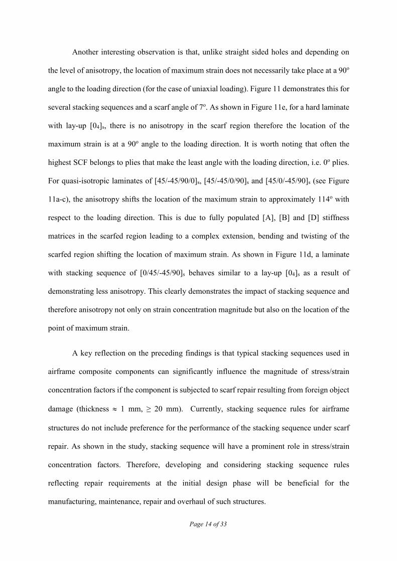
It is assumed that the structure is comprised of 8 unidirectional plies through the thickness with
mechanical properties as given in Table 1. The choice of 8 plies was adopted to not only cover
a wide spectrum of laminate homogenised stiffness values but also reduce computational effort
for a full parametric study. The orientation of each ply is arranged to give a balanced and
symmetric lay-up covering a wide spectrum of homogenised modulus of elasticity in x and y
directions as well as homogenised shear modulus (ranging between 5.58-30.63 MPa) in xy
plane. Moreover, the generated stacking sequences includes purely angle-plies, quasi-isotropic
(25%/50%/25% for plies 0/45/90), soft (10%/80%/10% for plies 0/45/90) and hard
(40%/20%/40% for plies 0/45/90) laminates. It is worth noting that soft and hard laminates are
often used for spar and skin components, respectively, and thus it is appropriate to study both.
This enabled the study of 46 different stacking sequences as given in Table A-1 of the appendix.
Page 12
Page 11 of 33
Two C3D8 (eight node linear brick elements) elements are used through the thickness
to represent each ply. Therefore, 16 elements represent the total thickness of the laminate as
shown in Figure 5. Boundary conditions and loading are designed to duplicate that of a uniaxial
tensile test. Hence, one end of the structure is assumed to be fully clamped, i.e. constrained
from rotating about x , y and z axes and displacing in x , y and z directions. However, the
loaded end of the structure is constrained from rotating about x , y and z axes and displacing
in y and z directions. A concentrated uniaxial tensile load of 37,500N is applied at a reference
point which is kinematically constrained to the loaded surface. This arrangement produces a
100MPa of average tensile stress on the loaded end. The other two edges are considered to be
free.
In the absence of experimental procedures, it is essential to verify the modelling
strategy of the numerical method. Hence, a comparison of the predicted strain concentration
value for a selected stacking sequence, [45/-45/0/90]s, was performed for a straight sided hole
against available analytical solutions given in (24,26). It is worth noting that the analytical
solution has been validated against both experimental and numerical procedures in various
literatures such as Taboul et al. (34) and Hufenbach et al. (31). The 2D analytical equation for
stress resultant/strain concentration ( tK ) in an infinite thin orthotropic plate with a central
straight sided hole is given by Equation (4).
1 22
x x
t xy
y xy
E EK
E Gυ
= + − +
(4)
This yields an analytical solution of 3tK = for the selected stacking sequence. As shown
in Figure 6, the numerical model yields a maximum strain of 0.006336 and a remote strain of
0.002154 giving a numerical solution of tK = 0.006336/0.002154= 2.94. This is in close
agreement with the analytical solution. Furthermore, a mesh sensitivity analysis was performed
Page 13
Page 12 of 33
(Figure 7) on the most shallow scarf angle, i.e. 3o, and 120 elements around the hole were
determined to provide appropriate accuracy for strain prediction.
5 Results and Discussion
Matching the verification process and to aid in creating easily interpretable generic
results concentration factors will be calculated from each simulation result. The maximum
predicted strain around the hole ( maxε ) is thus divided by the matching remote strain ( nε ) value
to give a strain concentration factor, henceforth denoted as STRCF (Equation 5).
max
n
STRCFεε
= (5)
Although the location with the highest STRCF is always at the edge of the hole (on the
scarfed surface), this cannot be concluded for the determination of the stress concentration
factor, henceforth denoted as SCF. For this, the distribution of STRCF along the scarf is
required. Often, plies that make the smallest angle with the loading direction, i.e. 0o plies, have
the highest SCF as they carry most of the load when compared with the off axis plies.
Therefore, in order to obtain SCF in scarfed composites, the distribution of strain is crucial
with SCF calculated using Equation 6. In which ixpE and nσ are the modulus of elasticity of ply
i in the loading direction and remote stress, respectively.
max ixp
t
n
ESCF K
θθε
σ
= =
(6)
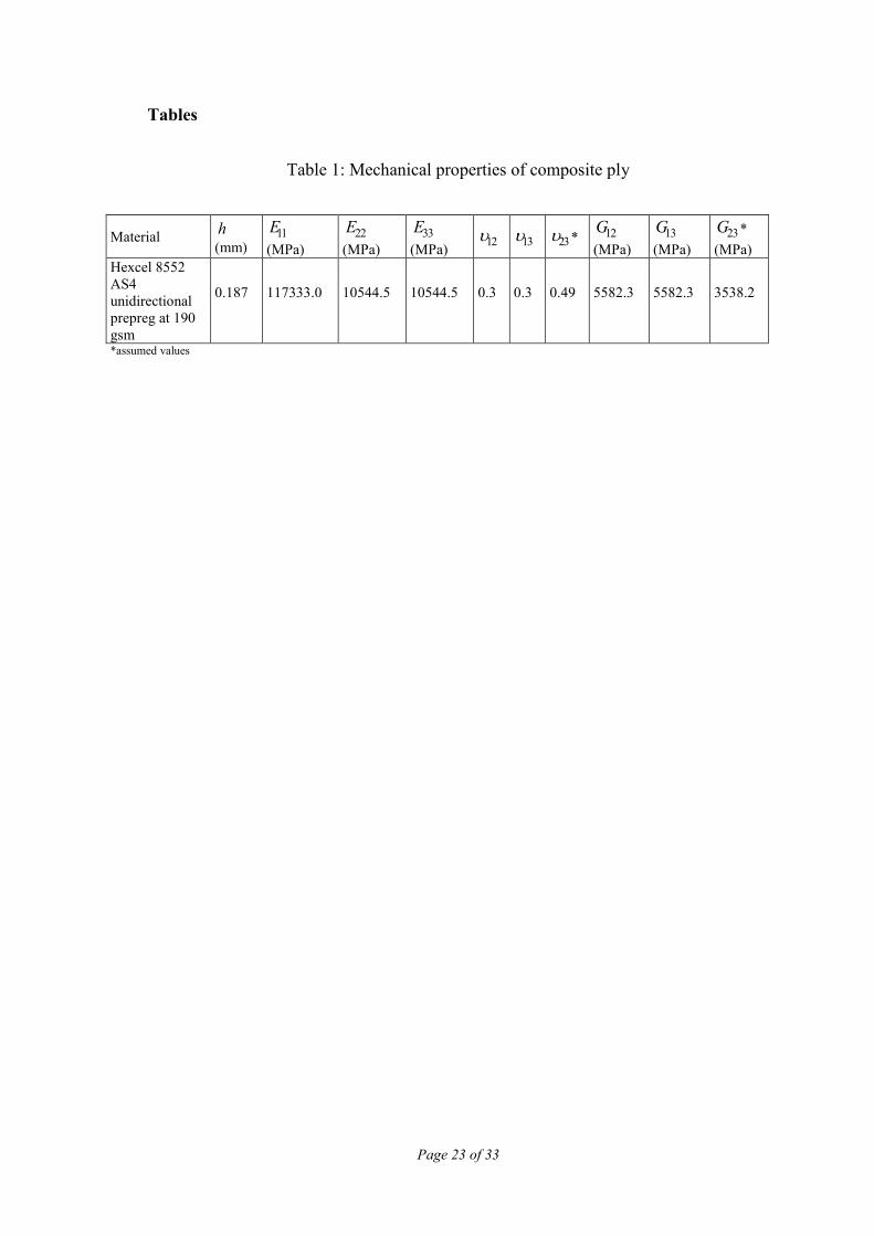
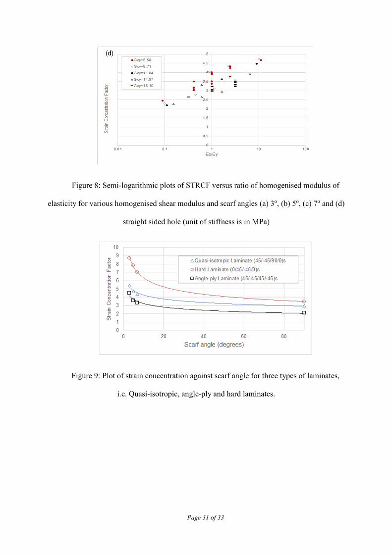
Figure 8 presents the values of STRCF against /x yE E ratio for various homogenised
values of xyG (see Table A-1). It is evident that all scarf angles, i.e. 3o, 5o and 7o (Figure 8a-c),
are demonstrating similar qualitative behaviour comparable to that of a straight sided hole
(Figure 8d). In other words, as it is expected from Equation (4) and numerical results show, a
Page 14
Page 13 of 33
higher ratio of /x yE E leads to higher SCF and STRCF for all test cases and scarf angles.
Moreover, laminates with higher xyG have lower SCF and STRCF although this is mostly
dependant on the ratio of /x xyE G rather than solely xyG , as can be inferred from Equation (4).
It is worth noting that in Figure 8 and for all test cases, the existence of several data points for
laminates of equal /x yE E ratio and xyG is associated to Poisson ratio effects ( xyυ ) for straight
sided holes resulting from different stacking sequences. This can be inferred from Equation
(4). However, the difference between STRCF of such laminates is significantly higher at a
scarfed hole than witnessed at a straight sided hole. A contributory factor to Poisson ratio
effects is bending, bending-stretching coupling and anisotropy in the scarfed region.
On the other hand, quantitative comparison of strain concentration suggests that STRCF
increases with the decrease of scarf angle for the same /x yE E and xyG . For example, STRCF
values for / 1x yE E = and xyG = 5.58 MPa are 1.88, 2.11 and 2.5 times higher than that of the
straight sided hole for scarf angles 7o, 5o and 3o, respectively. This demonstrates that scarfing
the composite could elevate strains by almost 2.5 times. Such phenomenon is illustrated for
three types of laminates, i.e. quasi-isotropic, angle-ply and hard laminates, in Figure 9.
Additionally, due to scarfing and therefore imposed anisotropy in the scarfed region,
notable out of plane deformation of the scarfed laminate takes place under the action of
membrane loading. This is accompanied by bending of the scarfed region about both the x and
y axes, as shown in Figure 10 for a typical quasi-isotropic stacking sequence, i.e. [45/-
45/90/0]s. As it can be seen from the figure, the lower the scarf angles, the higher the effect of
anisotropy induced bending, resulting in greater out of plane deformations. Therefore, for small
scarf angles a higher contribution of bending effects can be expected in the determination of
the STRCF.
Page 15
Page 14 of 33
Another interesting observation is that, unlike straight sided holes and depending on
the level of anisotropy, the location of maximum strain does not necessarily take place at a 90o
angle to the loading direction (for the case of uniaxial loading). Figure 11 demonstrates this for
several stacking sequences and a scarf angle of 7o. As shown in Figure 11e, for a hard laminate
with lay-up [04]s, there is no anisotropy in the scarf region therefore the location of the
maximum strain is at a 90o angle to the loading direction. It is worth noting that often the
highest SCF belongs to plies that make the least angle with the loading direction, i.e. 0o plies.
For quasi-isotropic laminates of [45/-45/90/0]s, [45/-45/0/90]s and [45/0/-45/90]s (see Figure
11a-c), the anisotropy shifts the location of the maximum strain to approximately 114o with
respect to the loading direction. This is due to fully populated [A], [B] and [D] stiffness
matrices in the scarfed region leading to a complex extension, bending and twisting of the
scarfed region shifting the location of maximum strain. As shown in Figure 11d, a laminate
with stacking sequence of [0/45/-45/90]s behaves similar to a lay-up [04]s as a result of
demonstrating less anisotropy. This clearly demonstrates the impact of stacking sequence and
therefore anisotropy not only on strain concentration magnitude but also on the location of the
point of maximum strain.
A key reflection on the preceding findings is that typical stacking sequences used in
airframe composite components can significantly influence the magnitude of stress/strain
concentration factors if the component is subjected to scarf repair resulting from foreign object
damage (thickness ≈ 1 mm, ≥ 20 mm). Currently, stacking sequence rules for airframe
structures do not include preference for the performance of the stacking sequence under scarf
repair. As shown in the study, stacking sequence will have a prominent role in stress/strain
concentration factors. Therefore, developing and considering stacking sequence rules
reflecting repair requirements at the initial design phase will be beneficial for the
manufacturing, maintenance, repair and overhaul of such structures.
Page 16
Page 15 of 33
6 Concluding remarks
In this paper, a critical assessment of current methodologies to determine stress/strain
concentration factors associated with large scarfed holes in composite laminates has
demonstrated that existing analytical methods are only appropriate within a constrained hole
diameter range. In particular, numerical analysis considering scarfed holes of diameter equal
to 20 mm have determined the existing methods to be inaccurate. It was demonstrated that the
use of computationally efficient quarter FEMs are not suitable to capture behaviour of scarfed
laminated composite structures. Hence, a series of three-dimensional full finite element models
were developed to understand the influence of stacking sequence and scarf angle on
strain/stress resultant concentrations under uniaxial tensile loading. The generated results have
enabled new understanding on the influence of laminate stacking sequence on strain/stress
concentration in thin laminates (≈ 1 mm) with large scarf angles and for the first time that strain
concentrations are not only dependant on the laminate membrane stiffness but also on laminate
bending stiffness, due to the anisotropy created as a result of the scarf angle. The qualitative
behaviour of STRCF of scarfed laminates is similar to straight sided holes. In other words,
strain distribution from the edge decays exponentially from the edge of the hole/scarf for both
straight sided holes and scarfed holes. Furthermore, the higher the homogenised shear modulus
of the laminate, the less is the stress/strain concentration value. However, quantitative analysis
clearly illustrates that smaller scarf angles lead to higher STRCF magnitudes. Scarfing with
low angles is demonstrated to elevate strains by a factor of 2.5 when compared with baseline
straight sided holes. Such high strain concentrations combined with imposed strain
concentrations arising from manufacturing processes such as machining and milling used for
scarfing could reduce the overall static and fatigue strength of the scarfed laminate
significantly. Additionally, unlike straight sided holes, peak stresses in scarfed laminates are
dependent on the strain distribution in the scarfed region and the stacking sequence of the
Page 17
Page 16 of 33
laminate, i.e. bending stiffness of the laminate. Moreover, the location of maximum strain does
not necessarily occur at 90o to the loading direction (for uniaxial loading) and maximum strain
location is again dependent on the level of anisotropy resulting from stacking sequence and
scarfing angle.
Page 18
Page 17 of 33
Appendix A
Table A-1: A summary of generated stacking sequences and their homogenised
mechanical properties
Page 19
Page 18 of 33
7 References
1. Yang C, Tomblin JS, Salah L. Stress model and strain energy release rate of a prescribed
crack in scarf joint/repair of composite panels. J Compos Mater [Internet].
2015;49(29):3635–63. Available from: http://dx.doi.org/10.1177/0021998314568326
2. Niedernhuber M, Holtmannspötter J, Ehrlich I. Fiber-oriented repair geometries for
composite materials. Vol. 94, Composites Part B: Engineering. 2016. p. 327–37.
3. Wang CH, Duong CN. Bonded Joints and Repairs to Composite Airframe Structures.
Bonded Joints and Repairs to Composite Airframe Structures. 2015. 1-295 p.
4. Ueda M, Miyake S, Hasegawa H, Hirano Y. Instantaneous mechanical fastening of
quasi-isotropic CFRP laminates by a self-piercing rivet. Compos Struct.
2012;94(11):3388–93.
5. Gerhard T, Friedrich C. Mechanical fastening of carbon composite tubes, numerical
calculation of axial loading capacity and experimental verification. Compos Part B Eng.
2014;67:391–9.
6. Soutis C, Duan DM, Goutas P. Compressive behaviour of CFRP laminates repaired with
adhesively bonded external patches. Compos Struct. 1999;45(4):289–301.
7. Campilho RDSG, De Moura MFSF, Domingues JJMS, Moura MFSFDE, Domingues
JJMS. Stress and failure analyses of scarf repaired CFRP laminates using a cohesive
damage model. J Adhes Sci Technol [Internet]. 2007;21(9):855–70. Available from:
http://openurl.ingenta.com/content/xref?genre=article&issn=0169-
4243&volume=21&issue=9&spage=855
8. Kweon JH, Jung JW, Kim TH, Choi JH, Kim DH. Failure of carbon composite-to-
aluminum joints with combined mechanical fastening and adhesive bonding. Compos
Page 20
Page 19 of 33
Struct. 2006;75(1–4):192–8.
9. Boisse P. Advances in composites manufacturing and process design. Advances in
Composites Manufacturing and Process Design. 2015.
10. Katnam KB, Da Silva LFM, Young TM. Bonded repair of composite aircraft structures:
A review of scientific challenges and opportunities [Internet]. Vol. 61, Progress in
Aerospace Sciences. 2013. p. 26–42. Available from: http://ac.els-
cdn.com/S0376042113000183/1-s2.0-S0376042113000183-main.pdf?_tid=aeabb794-
12d6-11e7-bc9c-
00000aacb35d&acdnat=1490610072_4690697fbe9b37e96cf9cd1723021b49
11. Errouane H, Sereir Z, Chateauneuf A. Numerical model for optimal design of composite
patch repair of cracked aluminum plates under tension. Int J Adhes Adhes. 2014;49:64–
72.
12. Saleem M, Toubal L, Zitoune R, Bougherara H. Investigating the effect of machining
processes on the mechanical behavior of composite plates with circular holes. Compos
Part A Appl Sci Manuf. 2013;
13. Hejjaji A, Zitoune R, Crouzeix L, Roux S Le, Collombet F. Surface and machining
induced damage characterization of abrasive water jet milled carbon/epoxy composite
specimens and their impact on tensile behavior. Wear [Internet]. Elsevier; 2017;376–
377:1356–64. Available from:
https://www.sciencedirect.com/science/article/abs/pii/S0043164817303332
14. Gunnion AJ, Herszberg I. Parametric study of scarf joints in composite structures.
Compos Struct. 2006;75(1–4):364–76.
15. Pinto AMGG, Campilho RDSGSG, De Moura MFSFSF, Mendes IR. Numerical
Page 21
Page 20 of 33
evaluation of three-dimensional scarf repairs in carbon-epoxy structures. In:
International Journal of Adhesion and Adhesives. 2010. p. 329–37.
16. Xiaoquan C, Baig Y, Renwei H, Yujian G, Jikui Z. Study of tensile failure mechanisms
in scarf repaired CFRP laminates. Int J Adhes Adhes. 2013;41:177–85.
17. Wang CH, Gunnion AJ. Optimum shapes of scarf repairs. Compos Part A Appl Sci
Manuf [Internet]. 2009;40(9):1407–18. Available from:
http://www.sciencedirect.com/science/article/pii/S1359835X09000451
18. Perillo G, Jørgensen JK, Cristiano R, Riccio A. A Numerical/Experimental Study on the
Impact and CAI Behaviour of Glass Reinforced Compsite Plates. Appl Compos Mater
[Internet]. 2018 Apr;25(2):425–47. Available from: https://doi.org/10.1007/s10443-
017-9628-2
19. Bendemra H, Compston P, Crothers PJ. Optimisation study of tapered scarf and stepped-
lap joints in composite repair patches. Compos Struct. 2015;130:1–8.
20. Wang CH, Gunnion AJ, Orifici AC, Rider A. Residual strength of composite laminates
containing scarfed and straight-sided holes. Compos Part A Appl Sci Manuf.
2011;42(12):1951–61.
21. Fotouhi M, Jalalvand M, Wisnom MR. Notch insensitive orientation-dispersed pseudo-
ductile thin-ply carbon/glass hybrid laminates. Compos Part A Appl Sci Manuf
[Internet]. Elsevier; 2018 Jul 1 [cited 2018 May 14];110:29–44. Available from:
https://www.sciencedirect.com/science/article/pii/S1359835X18301519
22. Zitoune R, Crouzeix L, Collombet F, Tamine T, Grunevald Y-H. Behaviour of
composite plates with drilled and moulded hole under tensile load. Compos Struct
[Internet]. 2011;93(9):2384–91. Available from:
Page 22
Page 21 of 33
http://www.sciencedirect.com/science/article/pii/S0263822311001115
23. Neuber H. G. N. Savin, Stress Concentration around Holes. XI + 430 S. m. 208 Abb. u.
77 Tafeln. Oxford/London/New York/Paris 1961. Pergamon Press. Preis geb. 84 s. net.
ZAMM - Zeitschrift für Angew Math und Mech [Internet]. WILEY‐VCH Verlag;
1962;42(6):265–265. Available from:
http://doi.wiley.com/10.1002/zamm.19620420618
24. Bonora N, Costanzi M, Marchetti M. On closed form solution for the elastic stress field
around holes in orthotropic composite plates under in-plane stress conditions. Compos
Struct [Internet]. 1993;25(1–4):139–56. Available from:
http://linkinghub.elsevier.com/retrieve/pii/026382239390160R
25. Chauhan MM, Sharma DS. Stresses in finite anisotropic plate weakened by rectangular
hole. Int J Mech Sci [Internet]. 2015;101–102:272–9. Available from:
http://linkinghub.elsevier.com/retrieve/pii/S0020740315002866
26. Makki MM, Chokri B. Experimental, analytical, and finite element study of stress
concentration factors for composite materials. J Compos Mater [Internet].
2017;51(11):1583–94. Available from: http://dx.doi.org/10.1177/0021998316659915
27. Sharma DS. Moment distribution around polygonal holes in infinite plate. Int J Mech
Sci. 2014;78:177–82.
28. Darwish F, Tashtoush G, Gharaibeh M. Stress concentration analysis for countersunk
rivet holes in orthotropic plates. Eur J Mech A/Solids. 2013;37:69–78.
29. Darwish F, Gharaibeh M, Tashtoush G. A modified equation for the stress concentration
factor in countersunk holes. Eur J Mech A/Solids. 2012;36:94–103.
Page 23
Page 22 of 33
30. Haque A, Ahmed L, Ramasetty A. Stress concentrations and notch sensitivity in woven
ceramic matrix composites containing a circular hole-an experimental, analytical, and
finite element study. J Am Ceram Soc [Internet]. 2005;88(8):2195–201. Available from:
https://ceramics.onlinelibrary.wiley.com/doi/full/10.1111/j.1551-2916.2005.00404.x
31. Hufenbach W, Grüber B, Gottwald R, Lepper M, Zhou B. Analytical and experimental
analysis of stress concentration in notched multilayered composites with finite outer
boundaries. Mech Compos Mater [Internet]. 2010 Dec;46(5):531–8. Available from:
https://doi.org/10.1007/s11029-010-9169-3
32. Grüber B, Gottwald R, Gude M, Lepper M, Modler N, Zhou B. Experimental Strain
Measurement for Fibre-Reinforced Finite Mulitlayered Composites with Cut-out Under
Bending for Validating an Analytical Calculation Model. Exp Tech [Internet].
2019;43(2):149–59. Available from: https://doi.org/10.1007/s40799-018-0275-9
33. Khechai A, Tati A, Guettala A. Finite element analysis of stress concentrations and
failure criteria in composite plates with circular holes. Front Mech Eng. 2014;9(3):281–
94.
34. Toubal L, Karama M, Lorrain B. Stress concentration in a circular hole in composite
plate. Compos Struct [Internet]. 2005;68(1):31–6. Available from:
https://www.sciencedirect.com/science/article/pii/S0263822304000522
Page 24
Page 23 of 33
Tables
Table 1: Mechanical properties of composite ply
Material h
(mm) 11E
(MPa)
22E
(MPa)
33E
(MPa) 12υ 13υ 23υ * 12G
(MPa)
13G
(MPa)
23G *
(MPa)
Hexcel 8552
AS4
unidirectional
prepreg at 190
gsm
0.187 117333.0 10544.5 10544.5 0.3 0.3 0.49 5582.3 5582.3 3538.2
*assumed values
Page 25
Page 24 of 33
Figures
Figure 1: Configuration of (a) countersunk hole and (b) a quarter FEM (28)
Page 26
Page 25 of 33
Figure 2: Strain ( xxε ) contour plot and boundary conditions of; (a) full scarf FEM; (b) a
quarter scarf FEM; (c) strain ( xxε ) plots along the line of symmetry for both models for
stacking sequence [45/-45/90/0]s
Page 27
Page 26 of 33
Figure 3: Hoop strain distribution vs the distance from the edge of the hole for scarf
angle of 3o, 5o , 7o and straight sided hole with stacking sequences; (a) quasi-isotropic
laminate of [45/-45/90/0]s, (b) hard laminate of [0/45/-45/0]s
Page 28
Page 27 of 33
Figure 4: Distribution of homogenised modulus of elasticity in load bearing direction,
xE , in the scarf region for scarf angle of 3o and stacking sequence [45/-45/90/0]s
Page 29
Page 28 of 33
Figure 5: Representation of the scarfed composite structure (scarf angle of 3o) for FEA
Figure 6: Contour plots of strains in x direction ( xxε ) for straight sided hole and
stacking sequence of [45/-45/0/90]s
Page 30
Page 29 of 33
Figure 7: Graph of mesh sensitivity study for scarf angle of 3o and stacking sequence
[45/-45/90/0]s
Page 32
Page 31 of 33
Figure 8: Semi-logarithmic plots of STRCF versus ratio of homogenised modulus of
elasticity for various homogenised shear modulus and scarf angles (a) 3o, (b) 5o, (c) 7o and (d)
straight sided hole (unit of stiffness is in MPa)
Figure 9: Plot of strain concentration against scarf angle for three types of laminates,
i.e. Quasi-isotropic, angle-ply and hard laminates.
Page 33
Page 32 of 33
Figure 10: Out of plane deformation of scarfed laminates for scarf angles (a) 3o, (b) 5o
and (c) 7o (loading is in direction of x axis and all dimensions are in millimetres)
Page 34
Page 33 of 33
Figure 11: Strain in loading direction for scarf angle of 7o and stacking sequences (a)
[45/-45/90/0]s, (b) [45/-45/0/90]s , (c) [45/0/-45/90]s , (d) [0/45/-45/90]s and (e) [04]s (loading
is in direction of x axis)