Understanding wear mechanisms – the application technology behind WR-Steel ® Adam Hylén, Head of Business & Product Development, Ovako Patrik Ölund, Head of R&D, Ovako Mersedeh Ghadamgahi, Project leader WR-Steel, Ovako Simon Lille, Senior R&D Engineer, Ovako Emil Svensson, Business Development, Ovako
Transcript
1
Understanding wear mechanisms – the application technology behind WR-Steel®
Adam Hylén, Head of Business & Product Development, Ovako Patrik Ölund, Head of R&D, Ovako Mersedeh Ghadamgahi, Project leader WR-Steel, Ovako Simon Lille, Senior R&D Engineer, OvakoEmil Svensson, Business Development, Ovako
2
EXECUTIVE OVERVIEW
WR-Steel®, which stands for wear resistant steel, includes a broad range of steel grades with a wide range of hardness levels, dimen-sions and compositions. WR-Steel® gives customers a wear-resistant advantage when they are manufacturing products exposed to a high degree of wear and where service life is important.
The aim in developing WR-Steel® was to combine cost efficiency at the manufacturing stage with optimum wear resistance in the end product. With three main metallurgies of billets, blooms and ingots, the WR-Steel® product range from Ovako is the broadest of its kind in Europe.
To fully appreciate the benefits of WR-Steel® it is crucial to understand the underlying mechanisms that result in wear. The aim of this white paper is to provide an overview of these physical processes, how they vary according to specific applications and how Ovako is combining field test work and labo-ratory testing to simplify the selection of steel grade in specific applications.
Some of the key learning points highlighted in this white paper are:
• Wear is specific to the application and the environmental factors in that application.• In the same application, a change in position on the component can leads to changes in the wear mechanism. For example, the wear mechanism can change according to the distance from the cutting edge of a plowing tool.• Carefully-controlled laboratory testing can replicate wear conditions found in the field• A combination of laboratory tests can produce a ranking of steels and provide information on selecting the best WR-Steel® for an application.• Wear is a system property. Therefore, several properties should be considered to cover all wear conditions in an application.• The concept of a wear ‘property zone’ is introduced that illustrates the relationship between toughness, strength and abrasive resistance for different component types. For a specific application, the material and heat treatment combination should be selected to fit within the appropriate zone.
1 (19)
Understanding wear mechanisms - the application technology behind WR-Steel® Adam Hylén Simon Lille Patrik Olund Emil Svensson
Executive overview
WR-Steel®, which stands for wear resistant steel, includes a broad range of steel grades with a wide range of hardness levels, dimensions and compositions. WR-Steel® gives customers a wear-resistant advantage when they are manufacturing products exposed to a high degree of wear and where service life is important.
The aim in developing WR-Steel® was to combine cost efficiency at the manufacturing stage with optimum wear resistance in the end product. With three main metallurgies of billets, blooms and ingots, the WR-Steel® product range from Ovako is the broadest of its kind in Europe and includes more than 30 different types of boron steel and special grades for different applications.
To fully appreciate the benefits of WR-Steel® it is crucial to understand the underlying mechanisms that result in wear. This white paper provides an overview of these physical processes, how they vary according to specific applications and how Ovako is combining field test work and laboratory testing to simplify the selection of steel grade in specific applications.
3
1 INTRODUCTION
Steel is used to manufacture critical compo-nents in a range of demanding applications such as agriculture, construction equipment and mining. Together with fatigue and cor-rosion, wear is recognized as one of the three major factors limiting the life and performance of engineering components and the systems they serve, from large heavy machinery to tiny electronic devices.
Virtually every type of machinery is subject to wear. It can be caused by individual parts rubbing against each or by the abrasive effect of external materials. Whatever the cause, wear results in the loss of material from the rubbing surface. Eventually this will cause the machinery to no longer be fit for purpose and could result in complete failure.
The efforts to combat wear are a critical industrial consideration, not least because the cost of wear represents an enormous burden. For example, a moldboard plow is expected to have a service life of 2,000 hours. Yet repairs due to wear during that time can represent 150 percent of the plow’s initial purchase cost. And of course, there is the added cost of lost production while repairs are taking place.
There are different approaches to tackling wear. Sometimes components will be sub-jected to significant over-sizing to allow for a loss of material over their service life without premature failure. In other cases, materials will be selected that offer higher levels of wear resistance. In some cases, the use of more expensive high-performance steels will show a significant return on investment. Sometimes designers might even go as far as selecting cemented carbide materials.
In order to find the best way to reduce wear in industrial applications it is important to understand the various wear mechanisms that can occur. This is because there are a number of different types of wear and each requires a different practical approach to address them.
In this white paper we examine what wear is, how it occurs and how it is measured both in the laboratory and in the field. We conclude by introducing an approach that can help to identify the best material for a specific wear application.
4
2 – WHAT IS WEAR?
Wear is the progressive loss and permanent deformation of material that happens due to the abrasion between moving surfaces. This destructive phenomenon causes significant damage and consequently significant costs for industry resulting from the need for repair or replacement of worn components. Wear is found in almost every type of machinery where two surfaces have a relative motion against each other.
Wear of metals occurs by the plastic displace- ment of surface and near-surface material and by the detachment of particles that form wear debris. The size of the generated particles may vary from the millimeter range down to the nano-scale. Regardless of the size of the machinery, wear besides fatigue and corro-sion, is one of the most important factors in determining the service life of engineering components.
The damage caused by wear is twofold: mate-rial and dimensional reduction or the detach-ment of material from the worn piece. The former may cause increased clearances and vibration between the moving surfaces and in special cases even leads to fatigue failure. In the latter, the detached particles act as extra abrasives and contribute to a higher degree of three-body abrasion. Either way, wear causes tremendous operational costs, and there is an essential need for further investigations to eliminate these effects.
The level and the progression of wear is highly dependent on many different parameters, such as the operating temperature, impact loads, corrosive effects, etc. In general, wear progresses over three main stages:
a) Primary stage where the surfaces are adapting to each other. This stage can have very high or low wear rate depending on the roughness of the surfaces.b) Secondary stage when a steady wear rate can be seen. c) Tertiary stage when a very rapid wear rate usually leads to failure.
In reality, the progress of wear can be very complicated. Simulating it in the laboratory environment is therefore difficult. The main challenge with testing to establish a wear rate is to design the test in such a way that it is representative of the real conditions in the field. Specifically, the main challenges that wear experts must deal with is verification of wear tests in the laboratory, in comparison with the service life of real components.
Both lab and field test may have vague transi-tions between the stages. Wear tests must give a significant wear rate for different samples in order to provide a correct picture for ranking the grades of wear. In addition, the test needs to be feasible to carry out within the lab with acceptable repeatability.
Even though the importance of wear and abra-sion on the service life of machinery, as well as the associated difficulties of understanding and testing it, is well known to the scientific community, there is still a major shortfall in investigations in this field. In this white paper, we present a general study and introduction of the different wear types and wear micro- mechanisms. It then progresses to review a major study on the surfaces of worn parts from different fieldwork studies. This provides a guideline to investigate any worn surface and address the dominant wear mechanism in the corresponding application. Describe how this knowledge can facilitate material selection for a certain application. By testing, studying and evaluating the wear of steel under representa-tive conditions it is possible to understand the processes taking place. This knowledge can then help designers to make a fully informed decision on the best material for their application.
5
3 – WEAR MECHANISMS
Wear behavior is very different in different applications. The first and most essential step in studying a wear problem is to understand the nature of the wear in the application and to identify the dominant wear mechanism that causes the major mass reduction of the wearing part.
In most wear applications, a combination of different wear mechanisms, such as abrasion, adhesion, fatigue, oxidation or other tribo- chemical actions are active and effective. In general, there are four main wear mecha-nisms that appear mostly in industrial applications. These wear mechanisms and their corresponding micro-mechanisms are:
An illustration of this categorization is shown in Fig 1.
Figure 1 – Categorization of wear mechanisms.
Addressing the dominant wear mechanism is an essential part of all wear studies, since it is the main reason for the mass loss and main damage to the worn part. This step leads to finding the corresponding solution to minimize the destructive effects of wear. There are two main methods used in these investigations: the first method is by survey-ing existing literature and relying on the simi-larities between the intended application and those previously studied. This method, which is mostly used in academic circles, is mainly suited for applications such as plows and scrapers where there is an established record of research into their wear mechanisms. The second method, which is more popular and reliable, especially in industrial research, is to investigate the worn part directly from field-work. This latter method is more expensive and difficult to implement, but it gives more accurate and reliable results with detailed information on the micro-mechanism of wear and further categorizations.
According to the literature, in applications associated with raw material handling equip-ment, such as in construction equipment and agriculture, the dominant wear mecha-nism is sliding abrasive wear. Examples of such studies are the work by Gonzalez et al. In this, the wear resistance of rotary plows operating in a clay loam soil was studied, with abrasive wear reported as the dominant wear mechanism. They report that the main wear micro-mechanisms are: micro-cutting, micro-plowing and plastic deformation on the cutting edge.
6
Abrasive wear occurs when a hard, rough surface slides across a softer surface. ASTM International (formerly American Society for Testing and Materials) defines it as the loss of material due to hard particles or hard protuberances that are forced against and move along a solid surface.
The mechanism of material removal in abra-sive wear is basically the same as machining and grinding during a manufacturing process. At the onset of wear, the hard asperities or particles penetrate into the softer surface under the normal contact pressure. When a tangential motion is imposed, the material of the softer surface is removed by the combined effects of abrasive micro-mechanisms. As a result, the worn surface is generally charac-terized by grooves and scratches. The wear debris often has the form of micro-cutting chips
Abrasive wear comprises a large family of different wear micro-mechanisms that, in an abrasive environment, cause the mass reduction of the worn surface. Addressing the dominant wear mechanism and identifying the corresponding corrective response is only possible when the micro-mechanisms active in the field are identified. This also makes it possible to further narrow down the catego-rization and develop the optimal solution for each application.
The following section describes the most important micro-mechanisms that take place in a variety of wear applications:
4 – ABRASIVE WEAR – DEFINITION AND MECHANISMS
Figure 2a – An illustration of micro- plowing alongside a scanning electron microscope (SEM) image showing the effect on a specimen.
Figure 2b – SEM image of wedge formation.
Figure 2c – SEM image of micro-cutting.
PlowingThis micro-mechanism (see Figure 2a) is mainly governed by plastic deformation. Sliding of the constrained abrasive particle occurs without material being removed from the wearing surface in the primitive stages of contact, but it is shifted to the sides of the wear groove. Although dis-attached material on the sides will be removed by further abrasive contact.
5 (19)
4 Abrasive wear – definition and mechanisms Abrasive wear occurs when a hard, rough surface slides across a softer surface. ASTM International (formerly American Society for Testing and Materials) defines it as the loss of material due to hard particles or hard protuberances that are forced against and move along a solid surface. The mechanism of material removal in abrasive wear is basically the same as machining and grinding during a manufacturing process. At the onset of wear, the hard asperities or particles penetrate into the softer surface under the normal contact pressure. When a tangential motion is imposed, the material of the softer surface is removed by the combined effects of abrasive micro-mechanisms. As a result, the worn surface is generally characterized by grooves and scratches. The wear debris often has the form of micro-cutting chips Micro-mechanisms of abrasive wear Abrasive wear comprises a large family of different wear micro-mechanisms that, in an abrasive environment, cause the mass reduction of the worn surface. Addressing the dominant wear mechanism and identifying the corresponding corrective response is only possible when the micro-mechanisms active in the field are identified. This also makes it possible to further narrow down the categorization and develop the optimal solution for each application. The following section describes the most important micro-mechanisms that take place in a variety of wear applications: Plowing This micro-mechanism is mainly governed by plastic deformation. Sliding of the constrained abrasive particle occurs without material being removed from the wearing surface in the primitive stages of contact, but it is shifted to the sides of the wear groove. Although dis-attached material on the sides will be removed by further abrasive contact.
Figure 2a - An illustration of micro-plowing alongside a scanning electron microscope (SEM) image showing the effect on a specimen..
6 (19)
Figure 2b – SEM image of wedge formation.
Figure 2c – SEM image of micro-cutting.
Wedge formation In this kind of deformation, the material is pushed to the front of the grit to form a wedge like shape, this grows until its eventual detachment and then the process begins again. Wedge formation is an intermediate mechanism between cutting and plowing. Cutting This micro-mechanism is mainly visible in applications with a higher impact of abrasives on the surfaces. In fact, the abrasive particle acts as a cutting tool and a chip is formed in front of its cutting edge as a result of the impact. In this case, lost material from the wearing surface occurs in a volume equal to the volume of the wear track (groove). This is the most severe form of abrasive wear in a ductile material. Cracking (brittle fracture) Cracking always occurs when highly concentrated stresses are imposed by high impact abrasive particles. Due to the poor plastic deformation ability of the material, large wear fragments are detached from the wearing surface owing to micro-crack formation and propagation. The volume of the lost material is higher than the volume of the wear track
Figure 3a.
7
Wedge formation In this kind of deformation, (see Figure 2b) the material is pushed to the front of the grit to form a wedge like shape, this grows until its eventual detachment and then the process begins again. Wedge formation is an inter-mediate mechanism between cutting and plowing.
CuttingThis micro-mechanism (see Figure 2c) is mainly visible in applications with a higher impact of abrasives on the surfaces. In fact, the abrasive particle acts as a cutting tool and a chip is formed in front of its cutting edge as a result of the impact. In this case, lost material from the wearing surface occurs in a volume equal to the volume of the wear track (groove). This is the most severe form of abrasive wear in a ductile material.
Cracking (brittle fracture)Cracking can occur when highly concentrated stresses are imposed by impact. Due to the poor plastic deformation ability of the mate-rial, wear fragments are detached from the wearing surface owing to micro-crack forma-tion and propagation as shown in Figure 3. The volume of the lost material is higher than the volume of the wear track.
Figure 3 - Micro-cracking.
Detailed knowledge of micro-mechanisms and the effect they can have on the material’s surface offers the possibility of investigating worn samples from the fieldwork to under-stand what processes are occurring in specific applications. The next sections of this white paper review some examples of this type of in-depth study.
7 (19)
Figure 3b.
Figure 3c. Figure 3 – There are a number of different types of micro-mechanism that resemble sliding abrasion wear a) micro-cutting b) micro-plowing c) micro-cracking (brittle fracture). Detailed knowledge of micro-mechanisms and the effect they can have on the material’s surface offers the possibility of investigating worn samples from the fieldwork to understand what processes are occurring in specific applications. The next sections of this white paper review some examples of this type of in-depth study. 5 Analysis of fieldwork An informative approach to understanding the nature of wear modes is to investigate samples from fieldwork. This offers a comprehensive picture of the active wear mechanisms. It also provides a useful tool for the designing of wear tests and deciding what steel properties are important for each application. This is illustrated here by three examples: a section of a Bolt On Edge (BOE), a tine point and a Down The Hole (DTH) drill head.
8
An informative approach to understanding the nature of wear modes is to investigate samples from fieldwork. This offers a com-prehensive picture of the active wear mecha-nisms. It also provides a useful tool for the designing of wear tests and deciding what steel properties are important for each application. This is illustrated here by three examples: a section of a Bolt On Edge (BOE), a tine point and a Down The Hole (DTH) drill head.
Bolt On Edge sample
5 – ANALYSIS OF FIELDWORK
Figure 5 – Worn piece from the BOE of a loader bucket.
In this case study, a section was taken from a Bolt On Edge (BOE) used on a wheel loader bucket. A BOE is used typically to provide a hard-wearing and easily replaceable cutting edge to the bucket.
The area of study focused on where the most extreme reduction in volume was taking place. It is also important to note that most (almost 98 percent) of the mass reduction due to wear is from the bottom part of the piece, where it is exposed to severe abrasive wear and impacted conditions, compared with the top region which is exposed to a slid-ing abrasive wear. This is explained in more detail and verified with SEM investigations.
SEM resultsFigures 6 and 7 show the SEM images of the sample taken from the bottom and top side of the BOE piece.
Figure 6 – SEM study on the bottom surface of the BOE.
8 (19)
Bolt On Edge sample
Figure 4 – Bolt On Edges play an important role in materials handling. In this case study, a section was taken from a Bolt On Edge (BOE) used on a wheel loader bucket. A BOE is used typically to provide a hard-wearing and easily replaceable cutting edge to the bucket. The area of study focused on where the most extreme reduction in volume was taking place. It is also important to note that most (almost 98 percent) of the mass reduction due to wear is from the bottom part of the piece, where it is exposed to severe abrasive wear and impacted conditions, compared with the top region which is exposed to a sliding abrasive wear. This is explained in more detail and verified with SEM investigations.
Figure 5 – Worn piece from the BOE of a loader bucket. SEM results Figures 6 and 7 show the SEM images of the sample taken from the bottom and top side of the BOE piece.
9 (19)
Figure 6 – SEM study on the bottom surface of the BOE.
9
The following conclusions were drawn from the investigation:
• The two pictures (Figures 6 and 7) are taken from the bottom and top parts of the section, at an equal distance from the edge. The extensive levels of plowing, wedge for mation and groove formations in both images indicate that the steel has been exposed to a sliding abrasive wear condi- tion. This effect is considerably more intense in the bottom part, due to the existence of impacted forces between the part and the soil. This can be verified by investigating the depth of debris in the bottom part compared to the upper part. • It is important to note that, even though there is a major difference in the intensity of the applied wear, the dominant wear mechanism is the same in both regions - sliding abrasive wear. • Even though the loss of material from the top is negligible compared to the bottom, further analysis is focused on that part since both bottom and top are subject to the same wear system. It is also easier to extrapolate the similarities between this part and the test samples since the final amount of lost material is almost similar for both of them. The limitation of apply- ing the sliding force and still staying in the low-impact zone is noticeable which is discussed further.
In order to investigate the micro-mecha-nisms, SEM images at greater magnification were examined. Figure 8 shows an image from the bottom, and Figure 9 the top surface of the BOE.
Figure 7 – SEM study on the top surface of the BOE.
Figure 8 – SEM study at higher magnifica-tion on the bottom surface of the BOE.
Figure 9 – SEM study at higher magnifica-tion on the top surface of the BOE.
10 (19)
Figure 7 – SEM study on the top surface of the BOE. The following conclusions were drawn from the investigation:
• The two pictures (Figures 6 and 7) are taken from the bottom and top parts of the section, at an equal distance from the edge. The extensive levels of plowing, wedge formation and groove formations in both images indicate that the steel has been exposed to a sliding abrasive wear condition. This effect is considerably more intense in the bottom part, due to the existence of impacted forces between the part and the soil. This can be verified by investigating the depth of debris in the bottom part compared to the upper part.
• It is important to note that, even though there is a major difference in the intensity of the applied wear, the dominant wear mechanism is the same in both regions - sliding abrasive wear.
• Even though the loss of material from the top is negligible compared to the bottom, further analysis is focused on that part since both bottom and top are subject to the same wear system. It is also easier to extrapolate the similarities between this part and the test samples since the final amount of lost material is almost similar for both of them. The limitation of applying the sliding force and still staying in the low-impact zone is noticeable which is discussed further.
In order to investigate the micro-mechanisms, SEM images at greater magnification were examined. Figure 8 shows an image from the bottom, and Figure 9 the top surface of the BOE.
11 (19)
Figure 8 – SEM study at higher magnification on the bottom surface of the BOE.
Figure 9 – SEM study at higher magnification on the top surface of the BOE. Closer examinations of the SEM images indicate that the main wear mechanism responsible for material removal is micro-plowing and micro-cutting. Brittle fractures are also seen on some parts, which indicate that the wear mechanism is combined with high compressive forces. On the other hand, the black spots shown on both sides are likely to be the effect of corrosion that indicates the
10
Closer examinations of the SEM images indi-cate that the main wear mechanism respon-sible for material removal is micro-plowing and micro-cutting. Brittle fractures are also seen on some parts, which indicate that the wear mechanism is combined with impact forces. On the other hand, the black spots shown on both sides are likely to be the effect of corrosion that indicates the possibility of dealing with a wet working condition. These pits are usually filled by slush and stone slurry later in the process. This can be seen by looking at the spectrum of the SEM elemental analysis as shown in Figure 10 and Table 1.
Figure 10 - Identification of the spectrums of the worn piece.
Table 1. Processing option: All elements analyzed (Normalized). All results in weight%
Table 1 shows a rather high percentage of silicon that indicates the existence of mud and slurry in the debris region.
SEM resultsClearly, most of the mass reduction took place across the width of the piece in the middle. This piece was cut into smaller sec-tions and investigations carried out as shown in Figure 12.
Figure 11 – Dimensional differences between a worn and new (tine) point.
Figure 12 – SEM investigation of the worn piece from the tine point.
Spectrum Al Si Cr Mn Fe Ni
Spectrum 1 8.69 34.21 0.51 0.66 55.54 0.40
Spectrum 2 9.10 40.11 0.19 0.40 50.20 0.00
Spectrum 3 7.52 30.05 0.32 0.58 61.52 0.00
Agricultural tine pointThis investigation focused on a typical steel tine point used in agricultural machinery applications such as harrows and cultivators. The tine point is the replaceable wear part that penetrates the soil and is exposed to wear.
The first step was to select the region with the most extreme wear, in order to obtain a complete picture of the wear condition. Figure 11 provides a comparison between a worn tine point, and a new one.
12 (19)
possibility of dealing with a wet working condition. These pits are usually filled by slush and stone slurry later in the process. This can be seen by looking at the spectrum of the SEM elemental analysis as shown in Figure 10 and Table 1.
Figure 10 - Identification of the spectrums of the worn piece. Table 1. Processing option: All elements analyzed (Normalized). All results in weight%
Table 1 shows a rather high percentage of silicon that indicates the existence of mud and slurry in the debris region. Agricultural tine point This investigation focused on a typical steel tine point used in agricultural machinery applications such as harrows and cultivators. The tine point is the replaceable wear part that penetrates the soil and is exposed to wear. The first step was to select the region with the most extreme wear, in order to obtain a complete picture of the wear condition. Figure 11 provides a comparison between a worn tine point, and a new one.
Figure 11 – Dimensional differences between a worn and new (tine) point. SEM results Clearly, most of the mass reduction took place across the width of the piece in the middle. This piece was cut into smaller sections and investigations carried out as shown in Figure 12.
Figure 12 – SEM investigation of the worn piece from the tine point. Figure 12 shows that the main active wear micro-mechanisms on this part of the (tine) point are: micro-plowing, wedge formation, micro-cutting, groove formation, brittle fracture in order of importance and dominance.
11
Figure 12 shows that the main active wear micro-mechanisms on this part of the (tine) point are: micro-plowing, wedge formation, micro-cutting, groove formation, brittle frac- ture in order of importance and dominance.
A comparison between the previous appli-cation (BOE) and the tine point indicates a difference between the wear microsystem in two environments, since the appearance and severity of some micro-mechanisms are very different. This shows that micro-mechanisms related to high impact are more visible in the BOE case, while the tine point is smoother with sliding effects. Although, for both cases sliding abrasion is still the dominant wear mechanism.
DTH Drill HeadAn investigation was carried out on a section of a drill bit from a down-the-hole (DTH) drill head used in a harsh wear induced en-vironment. Many previous studies have been done to understand the wear mechanisms in such applications, due to the major need to increase the service life of the steel part where the bits are mounted. This demand is even more significant in applications where a rapid improvement in drilling machinery increases the wear rates of the steel. An example of an investigation into this subject is the work by Professor Braham Prakash. In this study, a visual inspection was performed on the side of the drill bit, where most of the mass reduc-tion occurs. It was found that the abrasion in this type of application is caused by impact of the particles carried by the airflow.
To provide a closer look into the micro- mechanisms of wear in different regions of the drill bits, a surface study was done on a worn drill bit piece as shown in Figure 13.
Figure 13 – A DTH drill head showing a new component and different types of wear experienced.
In all the investigated areas, massive plastic deformations, with a large proportion of im-pact stresses were observed. Sharp, undefined particles attack the surface at random angles and cause micro- and macro- cutting and mass removal. There are also many brittle fractures observed, caused by the high impact and large angle of attack of the particles on the surface.
Wear mechanisms in applications such as rock drilling and mining, where abrasives meet the steel surface with a significant level of impact are not quite the same as the previous applications that are subject to mostly sliding abrasive effects. The dominant micro-wear mechanism in such applications is micro-cutting and brittle fractures, on the top side of the drill bits but also deep plowing effects on the sides.
The very different surface characteristics of the steel indicates the importance of treating and handling this type of wear with a relevant solution.
From these field tests it can be seen that each application creates different demands on the steel. The relevant wear mechanisms can even change in the same application depen-ding on the specific part of the application. This led Ovako to create our WR-Steel® selection methodology.
14 (19)
A comparison between the previous application (BOE) and the tine point indicates a difference between the wear microsystem in two environments, since the appearance and severity of some micro-mechanisms are very different. This shows that micro-mechanisms related to high impact are more visible in the BOE case, while the tine point is smoother with sliding effects. Although, for both cases sliding abrasion is still the dominant wear mechanism. DTH Drill Head An investigation was carried out on a section of a drill bit from a down-the-hole (DTH) drill head used in a harsh wear induced environment. Many previous studies have been done to understand the wear mechanisms in such applications, due to the major need to increase the service life of the steel part where the bits are mounted. This demand is even more significant in applications where a rapid improvement in drilling machinery increases the wear rates of the steel. An example of an investigation into this subject is the work by Professor Braham Prakash. In this study, a visual inspection was performed on the side of the drill bit, where most of the mass reduction occurs. It was found that the abrasion in this type of application is caused by impact of the particles carried by the airflow. To provide a closer look into the micro-mechanisms of wear in different regions of the drill bits, a surface study was done on a worn drill bit piece as shown in Figure 13.
Figure 13 – A DTH drill head showing a new component and different types of wear experienced. In all the investigated areas, massive plastic deformations, with a large proportion of impact stresses were observed. Sharp, undefined particles attack the surface at random angles and cause micro- and macro- cutting and mass removal. There are also many brittle fractures observed, caused by the high impact and large angle of attack of the particles on the surface. Wear mechanisms in applications such as rock drilling and mining, where abrasives meet the steel surface with a significant level of impact are not quite the same as the previous applications that are subject to mostly sliding abrasive effects. The dominant micro-wear mechanism in such applications is micro-cutting and brittle fractures, on the top side of the drill bits but also deep plowing effects on the sides.
12
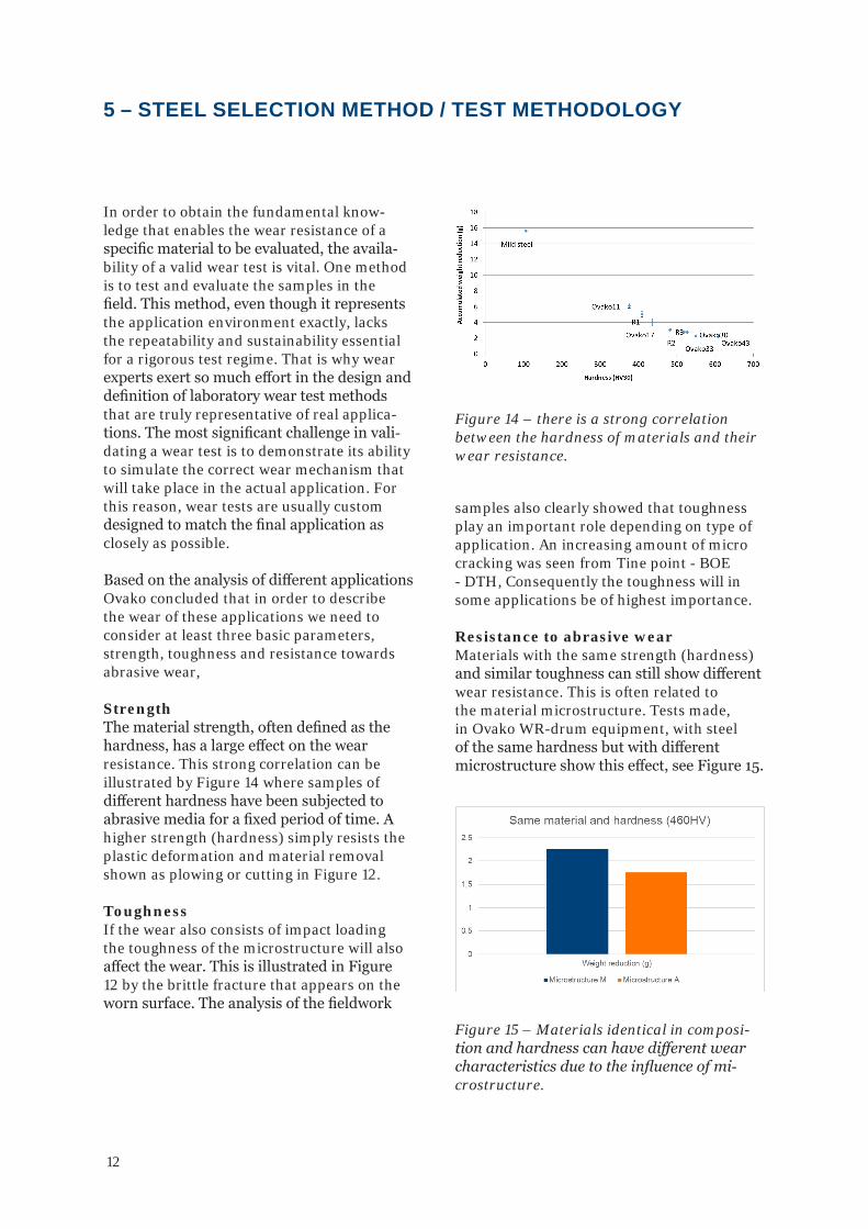
In order to obtain the fundamental know-ledge that enables the wear resistance of a specific material to be evaluated, the availa-bility of a valid wear test is vital. One method is to test and evaluate the samples in the field. This method, even though it represents the application environment exactly, lacks the repeatability and sustainability essential for a rigorous test regime. That is why wear experts exert so much effort in the design and definition of laboratory wear test methods that are truly representative of real applica-tions. The most significant challenge in vali-dating a wear test is to demonstrate its ability to simulate the correct wear mechanism that will take place in the actual application. For this reason, wear tests are usually custom designed to match the final application as closely as possible. Based on the analysis of different applications Ovako concluded that in order to describe the wear of these applications we need to consider at least three basic parameters, strength, toughness and resistance towards abrasive wear,
StrengthThe material strength, often defined as the hardness, has a large effect on the wear resistance. This strong correlation can be illustrated by Figure 14 where samples of different hardness have been subjected to abrasive media for a fixed period of time. A higher strength (hardness) simply resists the plastic deformation and material removal shown as plowing or cutting in Figure 12.
ToughnessIf the wear also consists of impact loading the toughness of the microstructure will also affect the wear. This is illustrated in Figure 12 by the brittle fracture that appears on the worn surface. The analysis of the fieldwork
5 – STEEL SELECTION METHOD / TEST METHODOLOGY
Figure 14 – there is a strong correlation between the hardness of materials and their wear resistance.
Figure 15 – Materials identical in composi-tion and hardness can have different wear characteristics due to the influence of mi-crostructure.
samples also clearly showed that toughness play an important role depending on type of application. An increasing amount of micro cracking was seen from Tine point - BOE - DTH, Consequently the toughness will in some applications be of highest importance.
Resistance to abrasive wearMaterials with the same strength (hardness) and similar toughness can still show different wear resistance. This is often related to the material microstructure. Tests made, in Ovako WR-drum equipment, with steel of the same hardness but with different microstructure show this effect, see Figure 15.
15 (19)
The very different surface characteristics of the steel indicates the importance of treating and handling this type of wear with a relevant solution From these field tests it can be seen that each application creates different demands on the steel. The relevant wear mechanisms can even change in the same application depending on the specific part of the application. This led Ovako to create our WR-Steel® selection methodology. 6 Steel selection method / test methodology In order to obtain the fundamental knowledge that enables the wear resistance of a specific material to be evaluated, the availability of a valid wear test is vital. One method is to test and evaluate the samples in the field. This method, even though it represents the application environment exactly, lacks the repeatability and sustainability essential for a rigorous test regime. That is why wear experts exert so much effort in the design and definition of laboratory wear test methods that are truly representative of real applications. The most significant challenge in validating a wear test is to demonstrate its ability to simulate the correct wear mechanism that will take place in the actual application. For this reason, wear tests are usually custom designed to match the final application as closely as possible. Based on the analysis of different applications Ovako concluded that in order to describe the wear of these applications we need to consider at least three basic parameters, strength, toughness and resistance towards abrasive wear, Strength The material strength, often defined as the hardness, has a large effect on the wear resistance. This strong correlation can be illustrated by Figure 14 where samples of different hardness have been subjected to abrasive media for a fixed period of time.
Figure 14 – there is a strong correlation between the hardness of materials and their wear resistance. A higher strength (hardness) simply resists the plastic deformation and material removal shown as plowing or cutting in Figure 12. Toughness If the wear also consists of impact loading the toughness of the microstructure will also affect the wear. This is illustrated in Figure 12 by the brittle fracture that appears on the worn surface.
16 (19)
Resistance to abrasive wear Materials with the same strength (hardness) and similar toughness can still show different wear resistance. This is often related to the material microstructure. Tests made with the steel grade Ovako 497 of the same hardness but with different microstructure show this effect, see Figure 15.
Figure 15 – Materials identical in composition and hardness can have different wear characteristics due to the influence of microstructure. Consequently, Ovako adopted the approach to evaluate the wear resistance of a material based on these three parameters. Strength is determined with hardness measurements. The impact toughness is determined with Charpy-V impact testing. Finally, the resistance to abrasive wear is evaluated in an abrasive wear tester, developed in-house, see Figure 16. The test specimen is easily manufactured and the test is easy to perform. This enables the testing of materials used in actual applications.
Figure 16 – WR-drum at Ovako Group R&D. Selecting the most suitable material solution
13
Figure 16 – The Ovako WR-drum
Selecting the most suitable material solutionAll three parameters must match the actual wear conditions of the application. Material can easily be screened and suitable improve-ments can be identified and proposed.
Ovako WR-drumThe test drum creates an abrasive wear rank-ing. Ovako is currently using a laboratory test machine at Ovako group R&D, Hofors, Sweden, as shown in Figure 16. In the Ovako WR-drum, samples can be fastened on the edge of the drum or mixed in with the abra-sive media. The drum is loaded with a mea-sured amount of abrasives and suspension and the drum is spun at a defined rotational speed.
The combined results of the different tests provide a property zone that can be compared to the application needs for a certain compo-nent. As an example, some components such as machining tools are not subjected to any impact and it is mainly strength that is an iss-ue. A rock tool requires a large property zone with impact and abrasive resistance as main constituents. An agricultural component such as a tine may need less impact resistance but still require high abrasive resistance.
Figure 17 is schematic representation of property zones for some applications. A material and heat treatment combination should be selected to fit within the desired property zone.
Figure 17 – Schematic representation of the property zone for certain applications
Consequently, Ovako adopted the approach to evaluate the wear resistance of a material based on these three parameters.
Strength is determined with hardness mea- surements. The impact toughness is deter-mined with Charpy-V impact testing. Finally, the resistance to abrasive wear is evaluated in an abrasive wear tester, developed in- house, see Figure 16. The test specimen is easily manufactured and the test is easy to perform. This enables the testing of materials used in actual applications.
16 (19)
Resistance to abrasive wear Materials with the same strength (hardness) and similar toughness can still show different wear resistance. This is often related to the material microstructure. Tests made with the steel grade Ovako 497 of the same hardness but with different microstructure show this effect, see Figure 15.
Figure 15 – Materials identical in composition and hardness can have different wear characteristics due to the influence of microstructure. Consequently, Ovako adopted the approach to evaluate the wear resistance of a material based on these three parameters. Strength is determined with hardness measurements. The impact toughness is determined with Charpy-V impact testing. Finally, the resistance to abrasive wear is evaluated in an abrasive wear tester, developed in-house, see Figure 16. The test specimen is easily manufactured and the test is easy to perform. This enables the testing of materials used in actual applications.
Figure 16 – WR-drum at Ovako Group R&D. Selecting the most suitable material solution
From the investigations made, including laboratory tests, it is possible to draw the following conclusions:
• Wear is specific to the application and the environmental factors in that application.
• In the same application, the position on the component leads to changes in the wear mechanism, for example: distance from the edge.
• Wear is a system property, therefore several properties are needed to cover all wear conditions in an application.
• The Ovako WR Drum is an effective way of replicating real-life wear conditions in the laboratory.
• Laboratory tests can help identify the property zone that provides the ideal combination of properties such as tough- ness, strength and abrasive wear. This information can be used to create a ranking of steels and to help in the the selection of the best WR-Steel for a specific application.
A Gola. Carbide-free bainitic steels for wear and rolling contact fatigue resistant applica-tions. PhD thesis. University of Cambridge. 2018
M Lindroos. Experimental and numerical studies on the abrasive and impact behavior of wear steels. PhD thesis. Tampere University of technology. 2016
R Chattopadhyay. Green tribology. ASM Int. 2014
T S Eyre. Wear characteristics of metals. Tribology international. Oct 1976
H Gonzalez et al. Wear of rotary plows operating in a tropical clay loam soil. Eng. Agric. 2013
K Hokkirigawa et al. An experimental and theoretical investigation on ploughing, cutting and wedge formation during abrasive wear. Tribology int. 1988
K Kato et al. Wear mechanisms. Modern tribology handbook. 2001
N Ojala et al. Effect of test parameters on large particle high speed slurry erosion testing. Tribology. 2014
B Prakash. Wear and failure in mining applications. Presentation at Tampere Wear Centre – Hard Rock Seminar. 2014
15
ABOUT THE AUTHORS
Emil SvenssonEmil Svensson is a part of the Business development department at Ovako SmeBox, as well as Segment leader for Wear Parts. Holds a Master’s Degree in Material Scien-ce, educated at Dalarna University (2002–2006). Work experience has included wor-king for Voestalpine as Product Specialist for Valve Steel. Emil joined Ovako in 2014, and has worked with Technical Support Service, Product- and Business Development since then.
Simon Lille Simon Lille is a senior researcher in group research and development at Ovako. Edu-cated at The Royal Institute of Technology (KTH, Stockholm, Sweden (1992–2002)) where he presented his PhD in Metallurgy. He worked with R&D and production at Outokumpu Stainless before coming to Ovako in 2012. He has worked as a production manager at the steel mill in Hofors. Now he is part of the R&D team and specializes in material investigations and production support.
Adam Hylén Adam Hylén is Head of Business and Product development at Ovako Smebox. He has a Bachelor Degree with a major in material science from Bergsskolan, School of mining and metallurgy (1996–2000). Joined Ovako 2001 and has experience with process and product development at the Ovako site in Boxholm. Between 2006 and 2009 he worked as Technical Manager at the Ovako sales unit in North America. He started to work with Business Development 2012 and been part of the Ovako Wear Team since 2014.
Patrik ÖlundPatrik Ölund is head of group research and development at Ovako. Educated at The Royal Institute of Technology (KTH, Stock-holm, Sweden (1985–1990), he worked at the Swedish Institute for Metals Research (1990–1995) doing research relating to in-clusions, fatigue and heat treatment. In 1995 he joined Ovako in the research department, which he now heads. Most recently, Ölund was this year’s winner of the Kami Prize 2013, presented to a distinguished scientist whose research has become the basis of a technical development within the Swedish steel and metal industry.
Mersedeh Ghadamgahi Educated with two Masters and an industrial PhD in The Royal Institute of Technology (KTH, Stockholm, Sweden (2012-2017). Her PhD research was on sustainability in industrial furnaces and heat treatment. She worked at the Ovako R&D department as project leader of Ovako WR steel (2013-2017), where she made in-depth research on fundamental of wear in different applications.
Ovako ABSE-111 87 Stockholm, Sweden
Phone: +46 (0)8 622 13 00www.ovako.com
DisclaimerThe information in this document is for illustrative purposes only. The data and examples are only general recommendations and not a warranty or a guarantee. The suitability of a product for a specific application can be confirmed only by Ovako once given the actual conditions. The purchaser of an Ovako product has the responsibility to ascertain and control the applicability of the products before using them.
Continuous development may necessitate changes in technical data without notice. This document is only valid for Ovako material. Other material, covering the same international specifications, does not necessarily comply with the properties presented in this document.


![Wear Simulation - IntechOpen · map of Lim and Ashby [5] (Fig. 4), shows two wear mechanisms: delamination wear and mild oxidational wear. Both these mechanisms are considered mild](https://static.documents.pub/doc/80x56/6032bb673be82123830d2ce9/wear-simulation-intechopen-map-of-lim-and-ashby-5-fig-4-shows-two-wear-mechanisms.jpg)


