110
Uninterruptible Power Supply (UPS) S8BA-24D24DLF User’s Manual S8BA-24D24DLF ENGLISH
Uninterruptible Power Supply (UPS)S8BA-24D24DLF
User’s Manual
S8BA-24D24DLF
ENGLISH

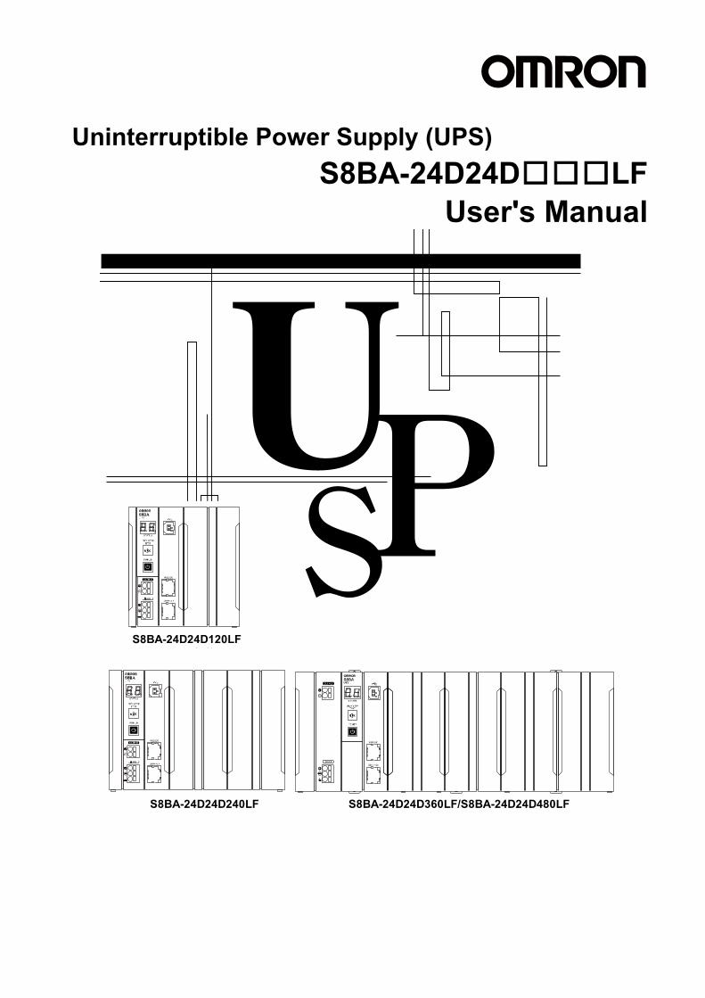
Uninterruptible Power Supply (UPS)
S8BA-24D24D□□□LF User's Manual
S8BA-24D24D120LF
S8BA-24D24D240LF S8BA-24D24D360LF/S8BA-24D24D480LF

Introduction
S8BA-24D24D□□□LF 1
Introduction Thank you for purchasing OMRON's Uninterruptible Power Supply (UPS). This manual contains information that is necessary to use the “Uninterruptible Power Supply (UPS)”. Read this manual carefully and make sure that you understand the functionality and performance of the product before using it in your system. Keep this manual in a safe place where it will be available for reference during operation.
Intended audience This manual is intended for: Personnel with knowledge of electric systems (the level of knowledge an electrical engineer has or its equivalent) and at the same time ▪ Personnel in charge of introducing FA systems ▪ Personnel in charge of designing FA systems ▪ Personnel in charge of installing and connecting FA systems ▪ Personnel in charge of managing FA systems and facilities
Applicable products This manual covers the following products: ▪ Uninterruptible Power Supply (UPS) S8BA Series
・S8BA-24D24D120LF ・S8BA-24D24D240LF ・S8BA-24D24D360LF ・S8BA-24D24D480LF
Important notice ▪ No part of this manual may be copied, reproduced, or used in any form without our permission. ▪ Note that the content of this manual such as the specifications is subject to change for improvement
without prior notice. ▪ We have checked the content of this manual and believe it to be accurate. However, if you find any
errors or have any questions, contact our sales personnel At that time, give the Man. No. (manual number) in the back of your manual.
Trademarks ▪ System names and product names indicated in this manual are registered trademarks or
trademarks of their respective owners.
Procedure from installation to operation
S8BA-24D24D□□□LF 2
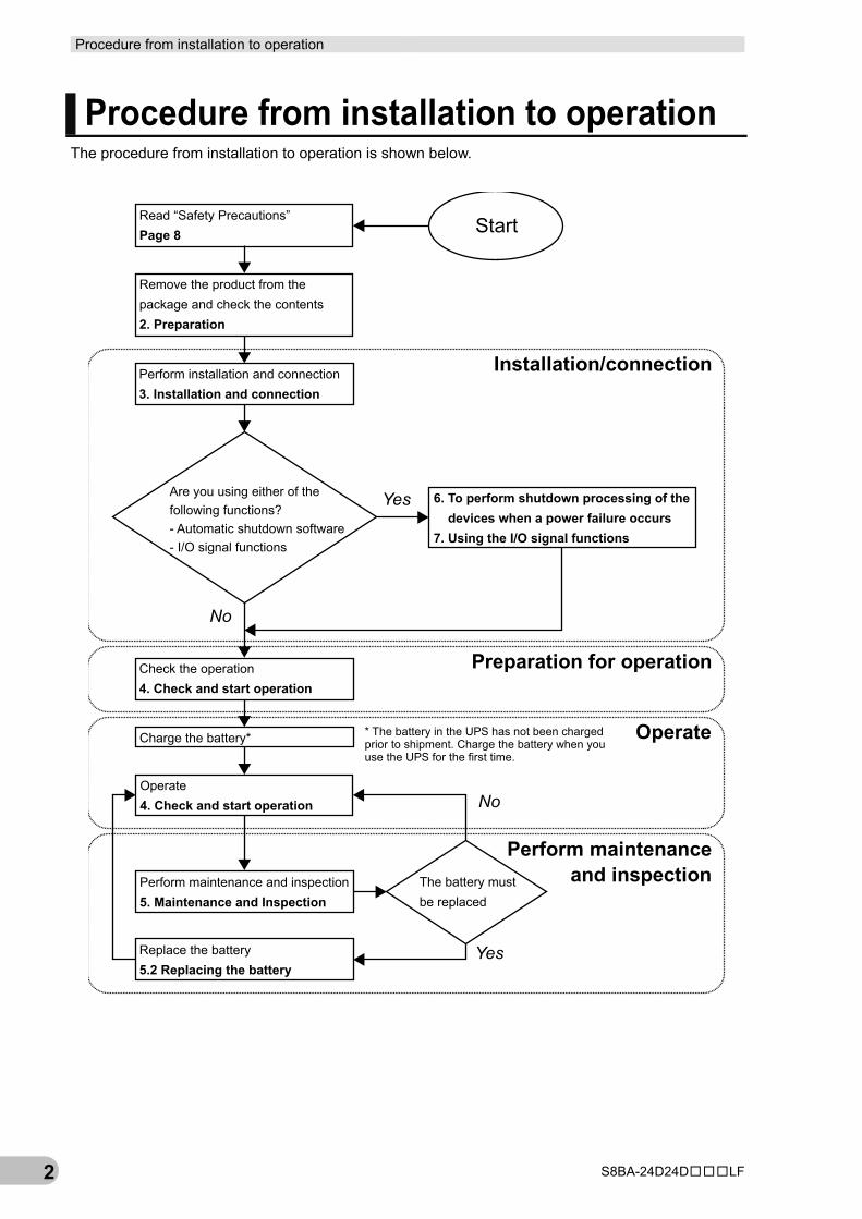
Procedure from installation to operation The procedure from installation to operation is shown below.
StartRead “Safety Precautions”Page 8
Remove the product from thepackage and check the contents2. Preparation
Perform installation and connection3. Installation and connection
Are you using either of thefollowing functions?- Automatic shutdown software- I/O signal functions
6. To perform shutdown processing of thedevices when a power failure occurs
7. Using the I/O signal functions
Check the operation4. Check and start operation
Charge the battery*
Operate4. Check and start operation
* The battery in the UPS has not been chargedprior to shipment. Charge the battery when youuse the UPS for the first time.
Perform maintenance and inspection5. Maintenance and Inspection
Replace the battery5.2 Replacing the battery
The battery mustbe replaced
Installation/connection
Preparation for operation
Operate
Perform maintenanceand inspection
Yes
No
No
Yes
Table of contents
S8BA-24D24D□□□LF 3
Table of contents Introduction .................................................................................................. 1 Procedure from installation to operation ...................................................... 2 Table of contents ......................................................................................... 3 Read and understand this manual ............................................................... 5 Safety precautions ....................................................................................... 8 Regulations and standards ........................................................................ 17 1 Overview of the product .................................................................... 19
1-1 Features of this product ............................................................................... 19 1-2 Specifications .............................................................................................. 20
2 Preparation ....................................................................................... 23 2-1 Unpacking the product ................................................................................ 23 2-2 Checking the contents ................................................................................. 23 2-3 Name of each part ....................................................................................... 25 2-4 Diagram of the Input/output circuit block ..................................................... 30
3 Installation and connection ................................................................ 31 3-1 Installation ................................................................................................... 31
3-1-1 DIN rail installation ............................................................................................................ 35 3-1-2 Wall or floor mounting procedure ...................................................................................... 37
3-2 Connection .................................................................................................. 41 3-2-1 Connecting a cable to the input terminal block and the output terminal block ................... 41 3-2-2 Connecting a device to the output terminal block .............................................................. 45 3-2-3 Connecting the input power supply to the input terminal block ......................................... 46
4 Check and start operation ................................................................. 47 4-1 The name and function for the operation and display ..................................... 47
4-1-1 Name of each part ............................................................................................................. 47 4-1-2 Switch ............................................................................................................................... 47 4-1-3 Beep sound ....................................................................................................................... 49
4-2 Start and stop procedures and basic operation ........................................... 50 4-2-1 Start and stop procedures ................................................................................................. 50
4-3 Interpreting beeps and displays .................................................................. 60
Table of contents
S8BA-24D24D□□□LF 4
4-4 UPS operation mode settings ...................................................................... 63 4-4-1 Settable items and explanations ........................................................................................ 63 4-4-2 Settings ............................................................................................................................. 66
5 Maintenance and inspection .............................................................. 73 5-1 Checking the battery .................................................................................... 73
5-1-1 Battery life expectancy ...................................................................................................... 73 5-1-2 Self-diagnosis test ............................................................................................................. 73 5-1-3 Estimated backup time ...................................................................................................... 74
5-2 Replacing the battery ................................................................................... 76 5-2-1 Notification that the battery needs to be replaced ............................................................. 77 5-2-2 Procedure for replacing the battery ................................................................................... 78
5-3 Cleaning ....................................................................................................... 85 6 To perform shutdown processing of the devices when a power failure occurs .......... 87
6-1 The outline on the UPS monitoring software ................................................ 87 6-1-1 What is the Simple Shutdown Software ............................................................................ 87 6-1-2 How to connect .................................................................................................................. 87
7 Using the I/O signal functions ............................................................ 91 7-1 I/O signal functions ...................................................................................... 91
7-1-1 Type of output signals ....................................................................................................... 91 7-1-2 Type of input signals .......................................................................................................... 91 7-1-3 I/O signal port (RJ45 connector) ........................................................................................ 92 7-1-4 Contact signal ratings ........................................................................................................ 92 7-1-5 Contact signal circuit ......................................................................................................... 92 7-1-6 Precautions and notes for the use of the I/O signal functions ........................................... 93 7-1-7 Example of the use of the Contact Signal circuit ............................................................... 93
8 Troubleshooting ................................................................................. 95 9 References ........................................................................................ 97
9-1 Dimensions .................................................................................................. 97 9-2 Characteristic data ..................................................................................... 100
Read and understand this manual
S8BA-24D24D□□□LF 5
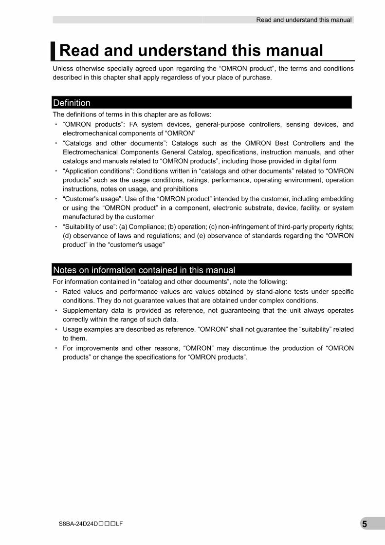
Read and understand this manual Unless otherwise specially agreed upon regarding the “OMRON product”, the terms and conditions described in this chapter shall apply regardless of your place of purchase.
Definition The definitions of terms in this chapter are as follows: ・ “OMRON products”: FA system devices, general-purpose controllers, sensing devices, and
electromechanical components of “OMRON” ・ “Catalogs and other documents”: Catalogs such as the OMRON Best Controllers and the
Electromechanical Components General Catalog, specifications, instruction manuals, and other catalogs and manuals related to “OMRON products”, including those provided in digital form
・ “Application conditions”: Conditions written in “catalogs and other documents” related to “OMRON products” such as the usage conditions, ratings, performance, operating environment, operation instructions, notes on usage, and prohibitions
・ “Customer's usage”: Use of the “OMRON product” intended by the customer, including embedding or using the “OMRON product” in a component, electronic substrate, device, facility, or system manufactured by the customer
・ “Suitability of use”: (a) Compliance; (b) operation; (c) non-infringement of third-party property rights; (d) observance of laws and regulations; and (e) observance of standards regarding the “OMRON product” in the “customer's usage”
Notes on information contained in this manual For information contained in “catalog and other documents”, note the following: ・ Rated values and performance values are values obtained by stand-alone tests under specific
conditions. They do not guarantee values that are obtained under complex conditions. ・ Supplementary data is provided as reference, not guaranteeing that the unit always operates
correctly within the range of such data. ・ Usage examples are described as reference. “OMRON” shall not guarantee the “suitability” related
to them. ・ For improvements and other reasons, “OMRON” may discontinue the production of “OMRON
products” or change the specifications for “OMRON products”.
Read and understand this manual
S8BA-24D24D□□□LF 6
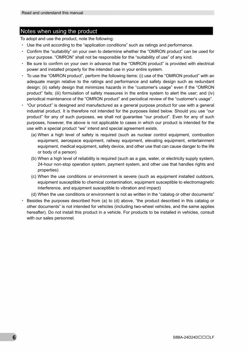
Notes when using the product To adopt and use the product, note the following: ・ Use the unit according to the “application conditions” such as ratings and performance. ・ Confirm the “suitability” on your own to determine whether the “OMRON product” can be used for
your purpose. “OMRON” shall not be responsible for the “suitability of use” of any kind. ・ Be sure to confirm on your own in advance that the “OMRON product” is provided with electrical
power and installed properly for the intended use in your entire system. ・ To use the “OMRON product”, perform the following items: (i) use of the “OMRON product” with an
adequate margin relative to the ratings and performance and safety design such as redundant design; (ii) safety design that minimizes hazards in the “customer's usage” even if the “OMRON product” fails; (iii) formulation of safety measures in the entire system to alert the user; and (iv) periodical maintenance of the “OMRON product” and periodical review of the “customer's usage”.
・ “Our product” is designed and manufactured as a general purpose product for use with a general industrial product. It is therefore not intended for the purposes listed below. Should you use “our product” for any of such purposes, we shall not guarantee “our product”. Even for any of such purposes, however, the above is not applicable to cases in which our product is intended for the use with a special product “we” intend and special agreement exists.
(a) When a high level of safety is required (such as nuclear control equipment, combustion equipment, aerospace equipment, railway equipment, elevating equipment, entertainment equipment, medical equipment, safety device, and other use that can cause danger to the life or body of a person)
(b) When a high level of reliability is required (such as a gas, water, or electricity supply system, 24-hour non-stop operation system, payment system, and other use that handles rights and properties)
(c) When the use conditions or environment is severe (such as equipment installed outdoors, equipment susceptible to chemical contamination, equipment susceptible to electromagnetic interference, and equipment susceptible to vibration and impact)
(d) When the use conditions or environment is not as written in the “catalog or other documents” ・ Besides the purposes described from (a) to (d) above, “the product described in this catalog or
other documents” is not intended for vehicles (including two-wheel vehicles, and the same applies hereafter). Do not install this product in a vehicle. For products to be installed in vehicles, consult with our sales personnel.
Read and understand this manual
S8BA-24D24D□□□LF 7
Warranty conditions The warranty conditions for the “OMRON product” are as follows: ・ Warranty period: For a period of 1 year from the date of purchase
(Unless otherwise described in “catalog or other documents”) ・ Warranty: Any of the following shall be performed on a faulty “OMRON product” at the discretion of
“OMRON”. (a) In-warranty repair of a faulty “OMRON product” at an OMRON maintenance service center
(note that repair is not applicable to electromechanical components.) (b) Supply of as many replacement products as the number of faulty “OMRON products” without
charge ・ Outside warranty: If the cause of the failure is any of the following, the failure shall be out of the
scope of warranty. (a) Use other than the originally designed use of the “OMRON product” (b) Use not compliant with the “application conditions” (c) Use against “Notes when using the product” in this chapter (d) Modification and/or repair not carried out by “OMRON” (e) Software program introduced not by “OMRON” (f) Anything that could not be predicted considering the level of science and/or technology at the
time of shipment from “OMRON” (g) Cause besides the above not attributable to “OMRON” or “OMRON products” (including force
majeure such as disasters)
Limitations of liability The warranty described in this chapter covers all the warranty related to the “OMRON product”. “OMRON” and distributors of “OMRON products” shall not be responsible for any damage that occurs and is related to “OMRON products”.
Export controls To export or provide to non-residents of Japan “OMRON products” or their technical documents, observe the laws and regulations of Japan and other related countries regarding security and export controls. Should you violate any laws or regulations, “OMRON products” or their technical documents may not be provided.
Safety precautions
S8BA-24D24D□□□LF 8
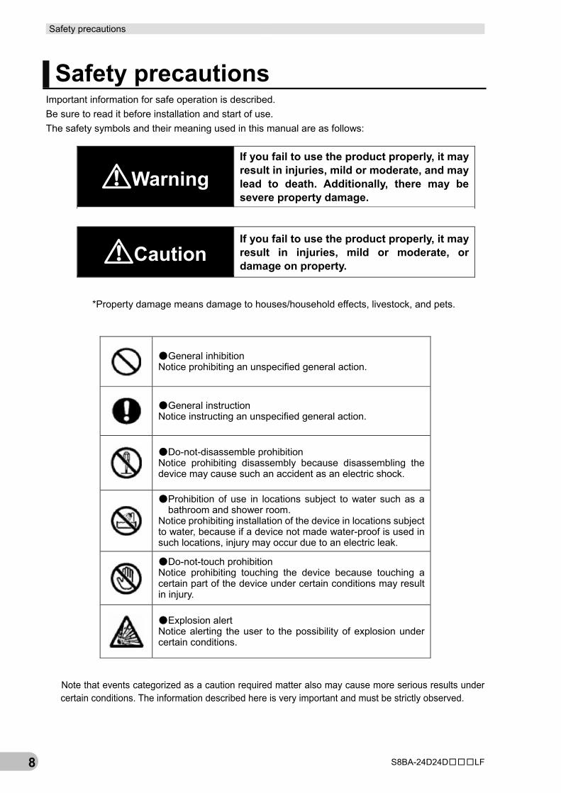
Safety precautions Important information for safe operation is described. Be sure to read it before installation and start of use. The safety symbols and their meaning used in this manual are as follows:
Warning If you fail to use the product properly, it may result in injuries, mild or moderate, and may lead to death. Additionally, there may be severe property damage.
Caution
If you fail to use the product properly, it may result in injuries, mild or moderate, or damage on property.
*Property damage means damage to houses/household effects, livestock, and pets.
●General inhibition Notice prohibiting an unspecified general action.
●General instruction Notice instructing an unspecified general action.
●Do-not-disassemble prohibition Notice prohibiting disassembly because disassembling the device may cause such an accident as an electric shock.
●Prohibition of use in locations subject to water such as a bathroom and shower room.
Notice prohibiting installation of the device in locations subject to water, because if a device not made water-proof is used in such locations, injury may occur due to an electric leak.
●Do-not-touch prohibition Notice prohibiting touching the device because touching a certain part of the device under certain conditions may result in injury.
●Explosion alert Notice alerting the user to the possibility of explosion under certain conditions.
Note that events categorized as a caution required matter also may cause more serious results under certain conditions. The information described here is very important and must be strictly observed.
Safety precautions
S8BA-24D24D□□□LF 9
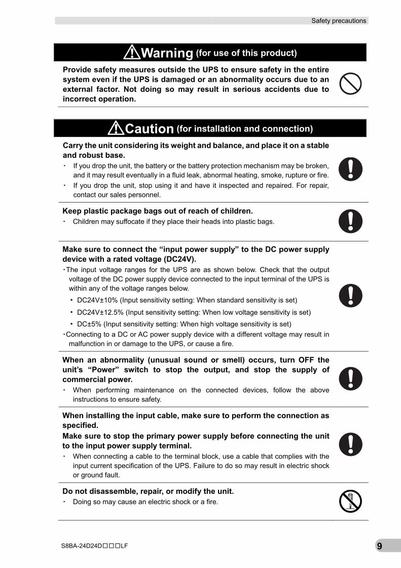
Warning (for use of this product) Provide safety measures outside the UPS to ensure safety in the entire system even if the UPS is damaged or an abnormality occurs due to an external factor. Not doing so may result in serious accidents due to incorrect operation.
Caution (for installation and connection) Carry the unit considering its weight and balance, and place it on a stable and robust base. ▪ If you drop the unit, the battery or the battery protection mechanism may be broken,
and it may result eventually in a fluid leak, abnormal heating, smoke, rupture or fire. ▪ If you drop the unit, stop using it and have it inspected and repaired. For repair,
contact our sales personnel.
Keep plastic package bags out of reach of children. ▪ Children may suffocate if they place their heads into plastic bags.
Make sure to connect the “input power supply” to the DC power supply device with a rated voltage (DC24V). ▪The input voltage ranges for the UPS are as shown below. Check that the output
voltage of the DC power supply device connected to the input terminal of the UPS is within any of the voltage ranges below.
▪ DC24V±10% (Input sensitivity setting: When standard sensitivity is set)
▪ DC24V±12.5% (Input sensitivity setting: When low voltage sensitivity is set)
▪ DC±5% (Input sensitivity setting: When high voltage sensitivity is set) ▪Connecting to a DC or AC power supply device with a different voltage may result in
malfunction in or damage to the UPS, or cause a fire.
When an abnormality (unusual sound or smell) occurs, turn OFF the unit’s “Power” switch to stop the output, and stop the supply of commercial power. ▪ When performing maintenance on the connected devices, follow the above
instructions to ensure safety.
When installing the input cable, make sure to perform the connection as specified. Make sure to stop the primary power supply before connecting the unit to the input power supply terminal. ▪ When connecting a cable to the terminal block, use a cable that complies with the
input current specification of the UPS. Failure to do so may result in electric shock or ground fault.
Do not disassemble, repair, or modify the unit. ▪ Doing so may cause an electric shock or a fire.
Safety precautions
S8BA-24D24D□□□LF 10
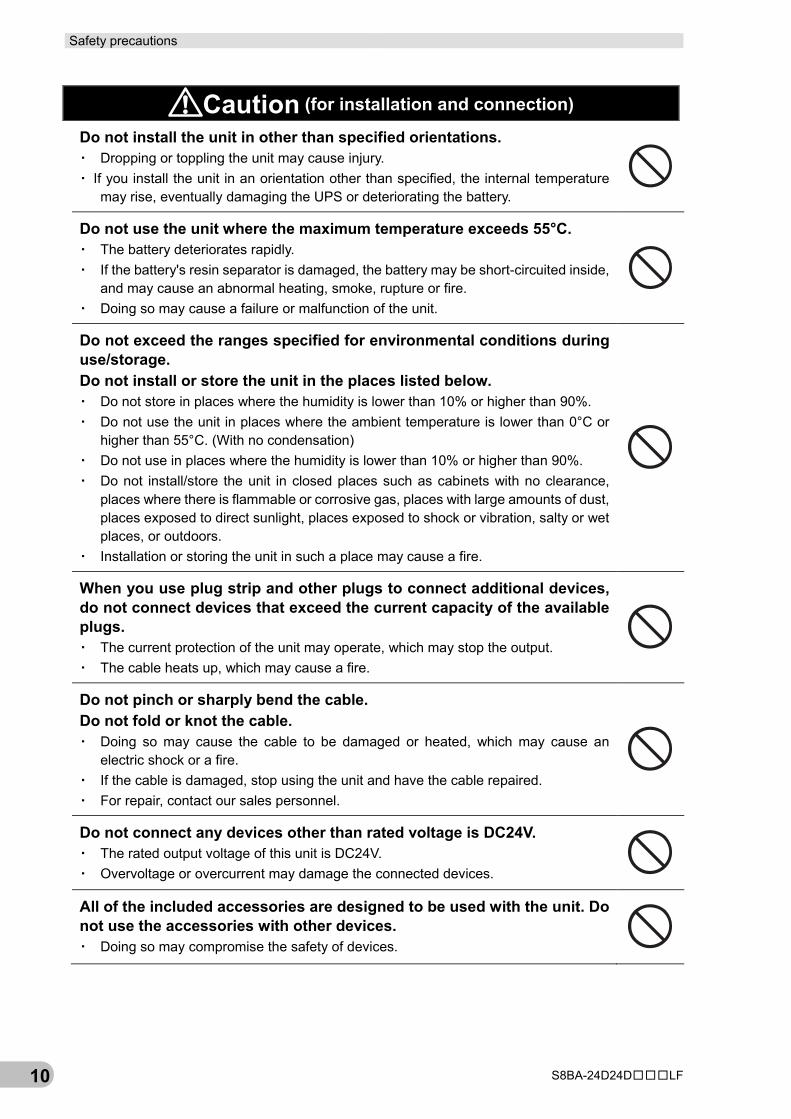
Caution (for installation and connection) Do not install the unit in other than specified orientations. ▪ Dropping or toppling the unit may cause injury. ▪ If you install the unit in an orientation other than specified, the internal temperature
may rise, eventually damaging the UPS or deteriorating the battery.
Do not use the unit where the maximum temperature exceeds 55°C. ▪ The battery deteriorates rapidly. ▪ If the battery's resin separator is damaged, the battery may be short-circuited inside,
and may cause an abnormal heating, smoke, rupture or fire. ▪ Doing so may cause a failure or malfunction of the unit.
Do not exceed the ranges specified for environmental conditions during use/storage. Do not install or store the unit in the places listed below. ▪ Do not store in places where the humidity is lower than 10% or higher than 90%. ▪ Do not use the unit in places where the ambient temperature is lower than 0°C or
higher than 55°C. (With no condensation) ▪ Do not use in places where the humidity is lower than 10% or higher than 90%. ▪ Do not install/store the unit in closed places such as cabinets with no clearance,
places where there is flammable or corrosive gas, places with large amounts of dust, places exposed to direct sunlight, places exposed to shock or vibration, salty or wet places, or outdoors.
▪ Installation or storing the unit in such a place may cause a fire.
When you use plug strip and other plugs to connect additional devices, do not connect devices that exceed the current capacity of the available plugs. ▪ The current protection of the unit may operate, which may stop the output. ▪ The cable heats up, which may cause a fire.
Do not pinch or sharply bend the cable. Do not fold or knot the cable. ▪ Doing so may cause the cable to be damaged or heated, which may cause an
electric shock or a fire. ▪ If the cable is damaged, stop using the unit and have the cable repaired. ▪ For repair, contact our sales personnel.
Do not connect any devices other than rated voltage is DC24V. ▪ The rated output voltage of this unit is DC24V. ▪ Overvoltage or overcurrent may damage the connected devices.
All of the included accessories are designed to be used with the unit. Do not use the accessories with other devices. ▪ Doing so may compromise the safety of devices.
Safety precautions
S8BA-24D24D□□□LF 11
Caution (for installation and connection) Include a breaker between the “input power supply” of this unit and the DC power supply device. And install the breaker where it is easy to operate.
When this product is used in compliance with CE marking, please use under 2m communication cable.
Do not block the air vents (upper and lower). ▪ Doing so will cause the internal temperature to rise, which may cause the unit to fail
and the battery to deteriorate. ▪ For stationary installation, leave a space of 50 mm or more above the top, and for
installation using a DIN rail and screw clamps, leave a space of 50 mm or more above the top and below the bottom each..
Do not connect the RS232C port or the CONTACT port to a LAN device using a LAN cable. ▪ Connection to a LAN device may result in malfunction in or damage to the UPS or the
LAN device.
Caution (for use) Do not allow the unit to come in contact with water. If you drop the unit, stop using it. ▪ Doing so may cause an electric shock or a fire. ▪ Doing so may cause an abnormal heating, smoke, rupture, or fire on the battery. ▪ If the unit becomes wet or is dropped, immediately stop using it, disconnect the input
power supply from the wall outlet (commercial power source) and have it inspected and repaired.
▪ For repair, contact our sales personnel.
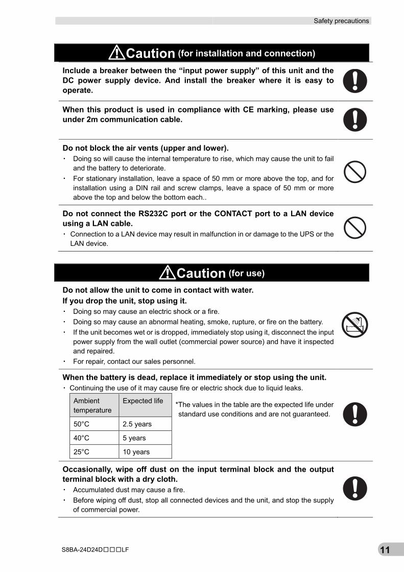
When the battery is dead, replace it immediately or stop using the unit. ▪ Continuing the use of it may cause fire or electric shock due to liquid leaks.
Ambient temperature
Expected life *The values in the table are the expected life under standard use conditions and are not guaranteed.
50°C 2.5 years
40°C 5 years
25°C 10 years
Occasionally, wipe off dust on the input terminal block and the output terminal block with a dry cloth. ▪ Accumulated dust may cause a fire. ▪ Before wiping off dust, stop all connected devices and the unit, and stop the supply
of commercial power.
Safety precautions
S8BA-24D24D□□□LF 12
Caution (for use) Do not use the unit in a closed place and do not cover the unit. ▪ Doing so may cause abnormal heating or a fire.
If you notice something unusual such as abnormal sound or smell, discoloration, deformation, and heating, turn OFF the unit's “Power” switch to stop the output and stop the supply from the “input power supply”. ▪ Using the unit under such conditions may cause an abnormal heating, rupture or fire. ▪ If you notice such a condition, stop using the unit and contact our sales personnel
for inspection and repairs. ▪ A readily accessible disconnect device shall be incorporated external to the
equipment.
If fluid leaks from the interior, do not touch the fluid. ▪ Doing so may cause blindness or burns. ▪ If the fluid contacts your eyes or skin, wash it out with lots of clean water and consult
your doctor. The fluid may damage your eye if your eye is left untreated.
Do not place any objects on the unit, and do not drop heavy objects onto the unit. ▪ Doing so may cause distortion/damage to the case or a failure of the internal circuit,
which may cause a fire.
The unit is equipped with a bypass circuit which is able to supply electric power to connected devices even when the inner control circuit is broken down by defects or malfunctions. If you want to stop the output, stop the source of the “input power supply”. ▪ Output is continuing even when all indicators of the front panel are off. ▪ Output ON/OFF cannot be controlled with the “Power” switch on the front panel.
When charging the battery, if the battery cannot be charged completely even after the predetermined charging time, turn OFF the “Power” switch of the unit to stop charging the battery. ▪ Otherwise, it may cause an abnormal heating, smoke, rupture or fire on the battery.
Caution (for maintenance) When maintaining the connected equipment, turn OFF the unit’s “Power” switch to stop the output, and stop the supply of the “input power supply”. ▪ Even if the input power supply to the UPS is stopped while it is in operation, the
power output of his unit does not stop and power is supplied from the battery.
Safety precautions
S8BA-24D24D□□□LF 13
Caution (for maintenance) Do not disassemble, repair, or modify the unit. ▪ Doing so may cause an electric shock or a fire.
If fluid leaks from the interior, do not touch the fluid. ▪ Doing so may cause blindness or burns. ▪ If the fluid contacts your eyes or skin, wash it out with lots of clean water and consult
your doctor.
Do not throw the unit into fire. ▪ Since the battery is incorporated in the unit, the insulator may melt, the gas exhaust
valve or protection mechanism may be damaged, or the electrolyte may catch fire, and it may result eventually in an abnormal heating, smoke, rupture or fire.
Do not insert metal objects into the input terminal block and the output terminal block of the UPS. ▪ Doing so may result in electric shock.
Do not insert metal objects into the battery connectors. Do not short between the connector terminals. ▪ Doing so may result in electric shock. ▪ The battery's protection board may be damaged due to a short-circuit.
Caution (for battery replacement) Risk of explosion if battery is replaced by an incorrect type. ▪ Not doing so may cause a fire. ▪ Battery pack for; product model: S8BA-B120L.
Do not replace the battery in a place where there is flammable gas. ▪ Spark may occur when connecting the battery, which may cause an explosion or fire.
If fluid leaks from the battery, do not touch the fluid. ▪ Doing so may cause blindness or burns. ▪ If the fluid contacts your eyes or skin, wash it out with lots of clean water and consult
your doctor.
Do not disassemble or modify the battery. ▪ A safety mechanism and protection mechanism to prevent danger are embedded
into the battery. If they are damaged, it may cause an abnormal heating, smoke, rupture or fire on the battery.
Safety precautions
S8BA-24D24D□□□LF 14
Caution (for battery replacement) Do not drop the battery and do not expose it to strong impact. ▪ Doing so may cause a leakage, abnormal heating, smoke, rupture or fire on the
battery. And, if the battery's protection mechanism is broken, the battery may be charged at an abnormal current or voltage, an abnormal chemical reaction may occur inside the battery, and it may result eventually in an abnormal heating, smoke, rupture or fire.
Do not short the battery with metal objects. ▪ Doing so could cause an electric shock, fire or burn. ▪ Some electrical energy still remains inside the spent battery.
Do not dispose of batteries in a fire. ▪ The insulator inside the battery may melt, the gas exhaust valve or protection
mechanism may be damaged, or the electrolyte may catch fire, and it may result eventually in abnormal heating, smoke, rupture or fire.
Do not use a new battery and an old battery at the same time. ▪ The battery may be excessively discharged while being used or excessively charged
while being charged, an abnormal chemical reaction may occur inside the battery, and it may result eventually in an abnormal heating, smoke, rupture or fire.
▪ A battery can present a risk of electrical shock and high short circuit current. ▪ Contact with any part of a grounded battery can result in electrical shock. ▪ The following precautions should be observed when working on batteries:
(a) Remove watches, rings, or other metal objects. (b) Use screwdrivers with insulated handles. (c) Wear rubber gloves and boots. (d) Do not lay tools or metal parts on top of batteries. (e) Remove battery grounds during installation and maintenance to reduce
likelihood of shock. Remove the connection from ground if any part of the battery is determined to be grounded.
Dispose of or collect (recycle) the battery according to your own rules set for that purpose or as instructed by laws and regulations. ▪ Do not dispose of it in fire. Otherwise, it could explode.
Safety precautions
S8BA-24D24D□□□LF 15
Notes
■ Before using Charge the battery soon after purchasing the unit.
▪ If you do not use the unit for a long time after the purchase, the battery may deteriorate and the battery may become unusable.
▪ Connect this unit to the input power supply and turn ON the “Power” switch to charge the battery.
When moving the unit from a cold place to a warm place, leave it for several hours before using it.
▪ If the unit is promptly turned ON after being moved to a warmer place, condensation may form inside the unit and cause it to fail.
Take measures for handling unforeseen accidents, such as data backup and system redundancy.
▪ The output may stop when there is failure in this unit.
■ Connecting Do not short the output lines of the unit to each other, and do not short the output lines to the ground.
▪ The unit may fail.
In the event you transfer or sell this unit to a third party, please include all of the documentation that came with the unit. This is to ensure that the unit is used in line with the conditions described in the included documentation.
▪ This manual contains important safety-related information. Please read and understand the contents of the manual before beginning operation. If this manual is misplaced, download the manual from our website.
Safety precautions
S8BA-24D24D□□□LF 16
■ Using Before stopping the input power supply to the unit, turn OFF the “Power” switch of the unit.
▪ The unit enters Battery Mode when input power supply is stopped.
▪ If the frequency of backup operation becomes high, the battery life may be significantly reduced.
Do not use for an application that frequently requires Battery Mode.
▪ The battery will deteriorate and fail to maintain the specified backup time.
If you want the UPS to stand by in a UPS startup state, set 3 months or less for the input power supply stop period.
▪ This UPS startup state means either of the following states: (a) A state of waiting for startup triggered by a remote ON/OFF or BS signal. (b) A state of waiting for startup when cold start is enabled.
▪ If the UPS is left unused in the above state for 3 months or longer, the battery goes into overdischarge state, and the backup time may become shorter or the battery may become unusable.
■ Storing Storing the battery in UPS for a long term, store at an environment less than 25°C and recharge 10 to 15 minutes the battery within 1 year.
▪ The battery self-discharges even when it not being used, and it goes into overdischarge state if it is left for a long period of time. The backup time may become shorter or the battery may become unusable.
▪ We recommend keeping the temperature 25°C or less when storing the unit for long periods of time.
▪ Turn OFF the unit’s “Power” switch when storing it.
Do not install or store the unit in a place exposed to direct sunlight.
▪ The rise of temperature may cause the built-in battery to deteriorate rapidly and become unusable.
Regulations and standards
S8BA-24D24D□□□LF 17
Regulations and standards Use overseas To export (or provide to non-residents of Japan) a model of this product that is categorized as a merchandise (or technology) requiring the export permission and approval stipulated by the Foreign Exchange and Foreign Trade Law, the export permission and approval (or service transaction permission) in accordance with the said law are required.
Conformance to EC Directives ●Applicable directives ▪ EMC Directives
●Principles regarding conformance OMRON electronic devices that comply with EC Directives also conform to the related EMC standards so that they can be more easily built into other devices or the overall machine. The actual products have been checked for conformity to EMC standards*. Whether the products conform to the standards in the system used by the customer, however, must be checked by the customer. EMC-related performance of the OMRON devices that comply with EC Directives will vary depending on the configuration, wiring, and other conditions of the equipment or control panel on which the OMRON devices are installed. The customer must, therefore, perform the final check to confirm that devices and the overall machine conform to EMC standards.
*Applicable EMC (Electromagnetic Compatibility) standards are as follows: EMS (Electromagnetic Susceptibility): EN 61000-6-2, EMI (Electromagnetic Interference): EN 61000-6-4, and EN 61000-6-4 Radiated emission: 10-m regulations
●Conformance to EC Directives This product complies with EC Directives. To ensure that the machine or device in which the this product is used complies with EC Directives, the product must be installed as follows: ▪ This product must be installed within a control panel. ▪ You must use reinforced insulation or double insulation for the DC power supply connected to this
product. ▪ Models of this product that comply with EC Directives also conform to the Common Emission
Standard. Radiated emission characteristics (10-m regulations), in particular, may vary depending on the configuration of the control panel used, other devices connected to the control panel, wiring, and other conditions. Therefore, even when using a model of this product that complies with EC Directives, you must confirm and ensure the compliance to EC Directives of the entire machine or equipment.
▪ This is a Class A product (for industrial environments). In a residential environment, it may cause radio interference. If radio interference occurs, the user may be required to take appropriate measures.
Regulations and standards
S8BA-24D24D□□□LF 18
●Conformance to UL ▪ This product must be installed within a control panel with an internal heater or other unit to protect
against the formation of condensation (Standard mounting only). ▪ Gaps in the door to the control panel must be completely filled or covered with gaskets or other
material. ▪ For use as a UL compliant device, the specifications for S8BA-24D24D480LF are as follows:
・ Maximum input current: 20A ・ Rated output current/capacity: 16.7A/400W
▪ For use in Pollution Degree 2 Environment. ▪ Surrounding Air Temperature, 55°C. ▪ Make sure to connect the device with Class 2 output to the USB port.
1-1 Features of this product 1 Overview of the product
S8BA-24D24D□□□LF 19
1
1 Overview of the product 1-1 Features of this product ▪ The Uninterruptible Power Supply (UPS) protects such devices as PLC and IPC* from power
failures, voltage variations, and instantaneous voltage drops. ▪ Under normal conditions, the UPS outputs DC24V of electrical power from the DC power supply
as-is. When an abnormality is detected in the DC24V power supply such as a power failure and voltage variation, the UPS switches to battery supply to continue to provide DC24V of electrical power.
▪ For the specifications of PLC and IPC for power supply input and operation in the event of momentary power interruptions, check the respective manuals. *IPC: Industrial PC (Industrial use computer)
1 Overview of the product 1-2 Specifications
S8BA-24D24D□□□LF 20
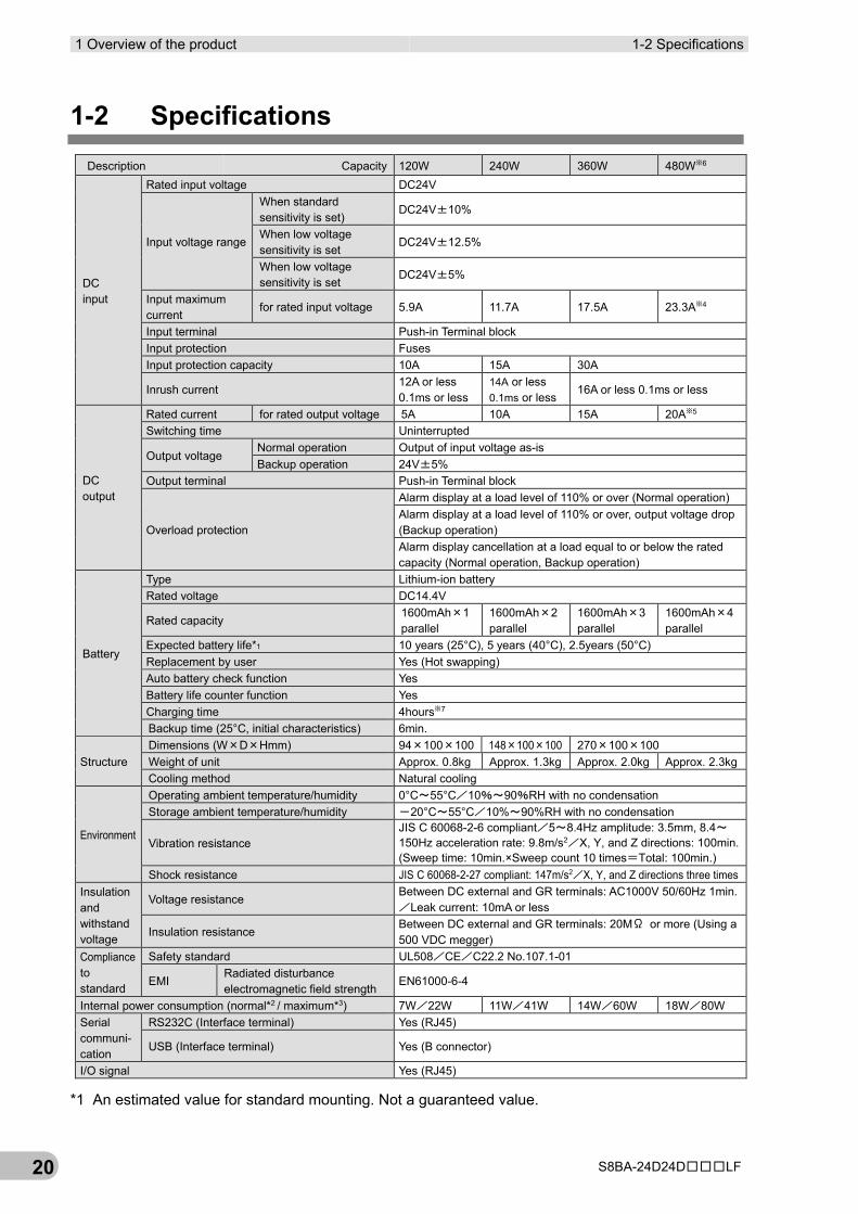
1-2 Specifications Description Capacity 120W 240W 360W 480W※6
DC input
Rated input voltage DC24V
Input voltage range
When standard sensitivity is set)
DC24V±10%
When low voltage sensitivity is set
DC24V±12.5%
When low voltage sensitivity is set
DC24V±5%
Input maximum current
for rated input voltage 5.9A 11.7A 17.5A 23.3A※4
Input terminal Push-in Terminal block Input protection Fuses Input protection capacity 10A 15A 30A
Inrush current 12A or less 0.1ms or less
14A or less 0.1ms or less
16A or less 0.1ms or less
DC output
Rated current for rated output voltage 5A 10A 15A 20A※5 Switching time Uninterrupted
Output voltage Normal operation Output of input voltage as-is Backup operation 24V±5%
Output terminal Push-in Terminal block
Overload protection
Alarm display at a load level of 110% or over (Normal operation) Alarm display at a load level of 110% or over, output voltage drop (Backup operation) Alarm display cancellation at a load equal to or below the rated capacity (Normal operation, Backup operation)
Battery
Type Lithium-ion battery Rated voltage DC14.4V
Rated capacity 1600mAh×1 parallel
1600mAh×2 parallel
1600mAh×3 parallel
1600mAh×4 parallel
Expected battery life*1 10 years (25°C), 5 years (40°C), 2.5years (50°C) Replacement by user Yes (Hot swapping) Auto battery check function Yes Battery life counter function Yes Charging time 4hours※7 Backup time (25°C, initial characteristics) 6min.
Structure Dimensions (W×D×Hmm) 94×100×100 148×100×100 270×100×100 Weight of unit Approx. 0.8kg Approx. 1.3kg Approx. 2.0kg Approx. 2.3kg Cooling method Natural cooling
Environment
Operating ambient temperature/humidity 0°C~55°C/10%~90%RH with no condensation Storage ambient temperature/humidity -20°C~55°C/10%~90%RH with no condensation
Vibration resistance JIS C 60068-2-6 compliant/5~8.4Hz amplitude: 3.5mm, 8.4~150Hz acceleration rate: 9.8m/s2/X, Y, and Z directions: 100min. (Sweep time: 10min.×Sweep count 10 times=Total: 100min.)
Shock resistance JIS C 60068-2-27 compliant: 147m/s2/X, Y, and Z directions three times Insulation and withstand voltage
Voltage resistance Between DC external and GR terminals: AC1000V 50/60Hz 1min./Leak current: 10mA or less
Insulation resistance Between DC external and GR terminals: 20MΩ or more (Using a 500 VDC megger)
Compliance to standard
Safety standard UL508/CE/C22.2 No.107.1-01
EMI Radiated disturbance electromagnetic field strength
EN61000-6-4
Internal power consumption (normal*2 / maximum*3) 7W/22W 11W/41W 14W/60W 18W/80W Serial communi-cation
RS232C (Interface terminal) Yes (RJ45)
USB (Interface terminal) Yes (B connector)
I/O signal Yes (RJ45)
*1 An estimated value for standard mounting. Not a guaranteed value.
1-2 Specifications 1 Overview of the product
S8BA-24D24D□□□LF 21
1
*2 Conditions: With rated loads connected, at a rated input voltage, and with the battery fully charged.
*3 Conditions: With rated loads connected, at a rated input voltage, and at the maximum battery charging current.
*4 20A for use as a UL compliant device.
*5 16.7A for use as a UL compliant device.
*6 400W for use as a UL compliant device.
*7 When using in an environment at a high temperature, charging may be paused by charging temperature protection, then the charging time will be longer than specified time. "CS" will be displayed when charging temperature protection is operated.

1 Overview of the product 1-2 Specifications
S8BA-24D24D□□□LF 22
2-1 Unpacking the product 2 Preparation
S8BA-24D24D□□□LF 23
2
2 Preparation 2-1 Unpacking the product
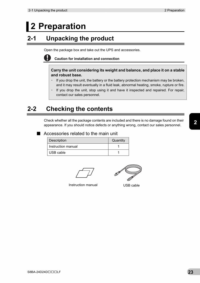
Open the package box and take out the UPS and accessories.
Caution for installation and connection
Carry the unit considering its weight and balance, and place it on a stable and robust base. ▪ If you drop the unit, the battery or the battery protection mechanism may be broken,
and it may result eventually in a fluid leak, abnormal heating, smoke, rupture or fire. ▪ If you drop the unit, stop using it and have it inspected and repaired. For repair,
contact our sales personnel.
2-2 Checking the contents Check whether all the package contents are included and there is no damage found on their appearance. If you should notice defects or anything wrong, contact our sales personnel.
■ Accessories related to the main unit Description Quantity
Instruction manual 1
USB cable 1
Instruction manual USB cable
2 Preparation 2-2 Checking the contents
S8BA-24D24D□□□LF 24
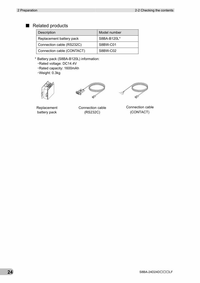
■ Related products Description Model number
Replacement battery pack S8BA-B120L*
Connection cable (RS232C) S8BW-C01
Connection cable (CONTACT) S8BW-C02
* Battery pack (S8BA-B120L) information: ▪Rated voltage: DC14.4V ▪Rated capacity: 1600mAh ▪Weight: 0.3kg
Connection cable�(RS232C)
Connection cable�(CONTACT)
Replacementbattery pack
2-3 Name of each part 2 Preparation
S8BA-24D24D□□□LF 25
2
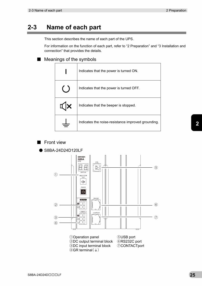
2-3 Name of each part This section describes the name of each part of the UPS.
For information on the function of each part, refer to “2 Preparation” and “3 Installation and connection” that provides the details.
■ Meanings of the symbols
Indicates that the power is turned ON.
Indicates that the power is turned OFF.
Indicates that the beeper is stopped.
Indicates the noise-resistance improved grounding.
■ Front view
● S8BA-24D24D120LF
①
②
③
⑤
⑥
⑦④
①Operation panel②DC output terminal block③DC input terminal block④GR terminal( )
⑤USB port⑥RS232C port⑦CONTACTport
2 Preparation 2-3 Name of each part
S8BA-24D24D□□□LF 26
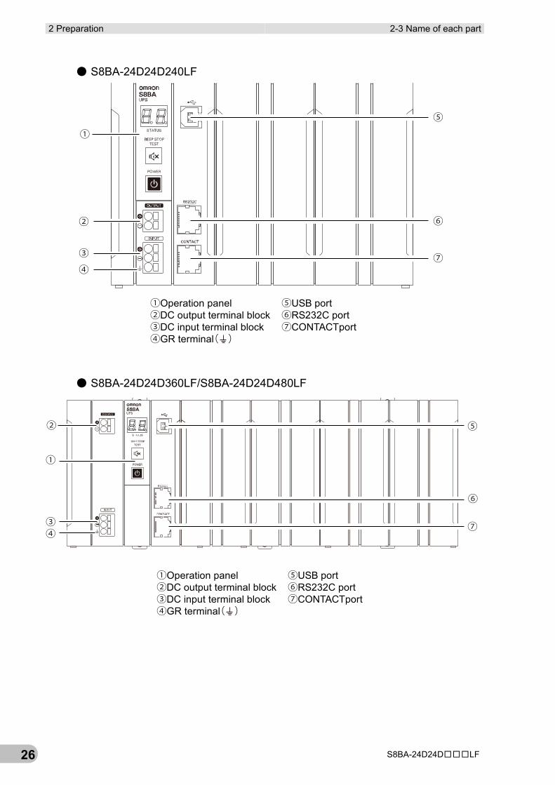
● S8BA-24D24D240LF
● S8BA-24D24D360LF/S8BA-24D24D480LF
①
②
③
⑤
⑥
⑦④
①Operation panel②DC output terminal block③DC input terminal block④GR terminal( )
⑤USB port⑥RS232C port⑦CONTACTport
①
②
③④
⑤
⑥
⑦
①Operation panel②DC output terminal block③DC input terminal block④GR terminal( )
⑤USB port⑥RS232C port⑦CONTACTport
2-3 Name of each part 2 Preparation
S8BA-24D24D□□□LF 27
2
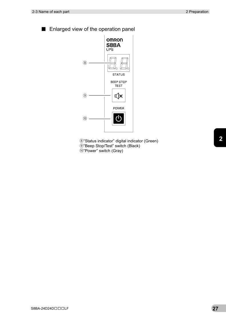
■ Enlarged view of the operation panel
⑧
⑨
⑩
⑧“Status indicator” digital indicator (Green)⑨“Beep Stop/Test” switch (Black)⑩“Power” switch (Gray)
2 Preparation 2-3 Name of each part
S8BA-24D24D□□□LF 28
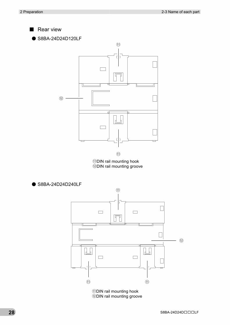
■ Rear view
● S8BA-24D24D120LF
● S8BA-24D24D240LF
⑪
⑪
⑫
⑪DIN rail mounting hook⑫DIN rail mounting groove
⑪
⑪ ⑪
⑫
⑪DIN rail mounting hook⑫DIN rail mounting groove
2-3 Name of each part 2 Preparation
S8BA-24D24D□□□LF 29
2
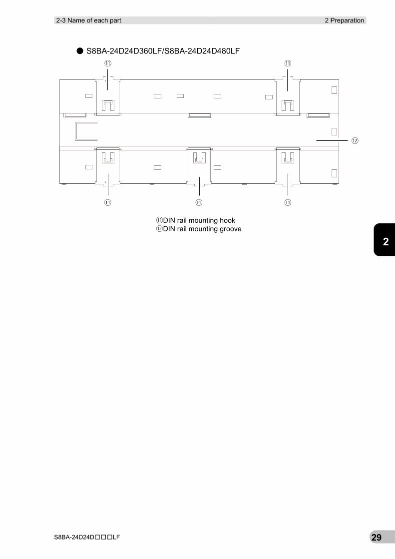
● S8BA-24D24D360LF/S8BA-24D24D480LF
⑪ ⑪
⑪⑪⑪
⑫
⑪DIN rail mounting hook⑫DIN rail mounting groove
2 Preparation 2-4 Diagram of the Input/output circuit block
S8BA-24D24D□□□LF 30
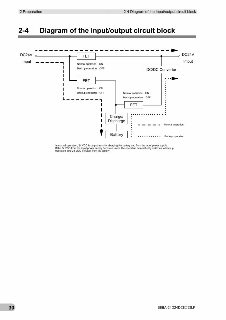
2-4 Diagram of the Input/output circuit block
Normal operation:ON
Backup operation:OFF
DC24V
Imput。 。DC24V
Imput
Normal operation:ON
Backup operation:OFF Normal operation:ON
Backup operation:OFF
Battery
DC/DC Converter
FET
Normal operation
Backup operation
FET
FET
Charge/Discharge
*In normal operation, 24 VDC is output as-is for charging the battery and from the input power supply.If the 24 VDC from the input power supply becomes lower, the operation automatically switches to backupoperation, and 24 VDC is output from the battery.
3-1 Installation 3 Installation and connection
S8BA-24D24D□□□LF 31
3
3 Installation and connection 3-1 Installation
This section describes how to install the UPS.
For cautions when installing the UPS, refer to “Caution (for installation and connection)” shown in the “Safety precautions” of the beginning of this manual.
The UPS permits the following installing methods. Choose the one best suited for the environment.
Notes
Before installing this device, make a record of the serial number of this device. The product serial number is required when contacting us about the device. The product serial number is written on the sticker attached to the side of the UPS.
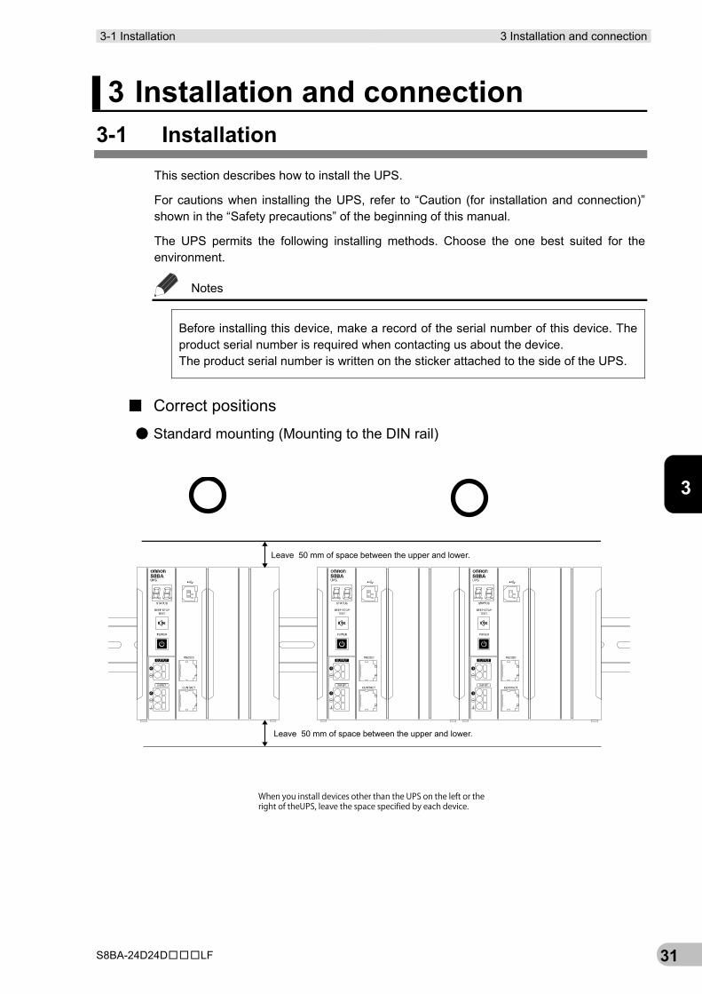
■ Correct positions
● Standard mounting (Mounting to the DIN rail)
When you install devices other than the UPS on the left or theright of theUPS, leave the space specified by each device.
Leave 50 mm of space between the upper and lower.
Leave 50 mm of space between the upper and lower.
3 Installation and connection 3-1 Installation
S8BA-24D24D□□□LF 32
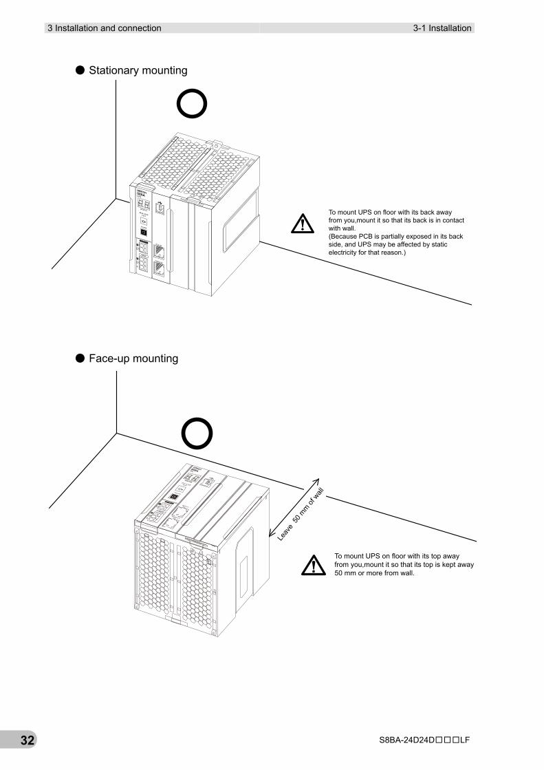
● Stationary mounting
● Face-up mounting
To mount UPS on floor with its back awayfrom you,mount it so that its back is in contactwith wall.(Because PCB is partially exposed in its backside, and UPS may be affected by staticelectricity for that reason.)
To mount UPS on floor with its top awayfrom you,mount it so that its top is kept away50 mm or more from wall.
Leav
e 50
mm of
wall
3-1 Installation 3 Installation and connection
S8BA-24D24D□□□LF 33
3
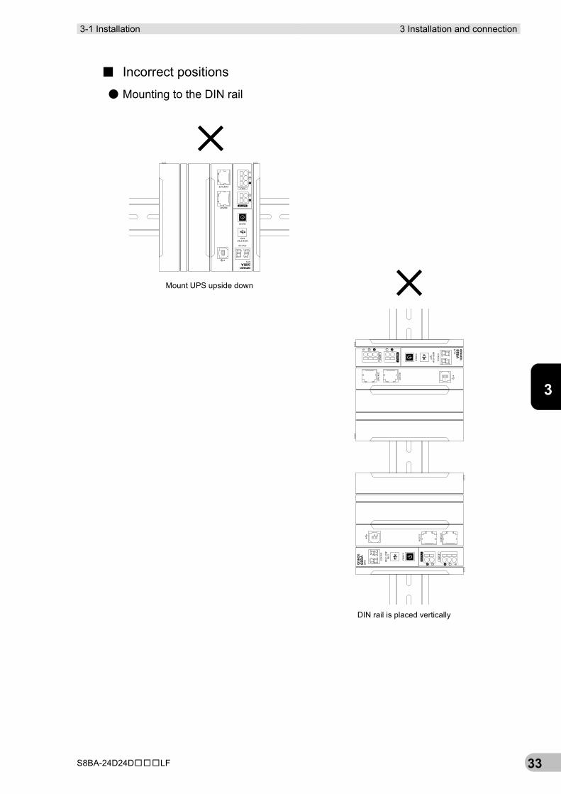
■ Incorrect positions
● Mounting to the DIN rail
Mount UPS upside down
DIN rail is placed vertically
3 Installation and connection 3-1 Installation
S8BA-24D24D□□□LF 34
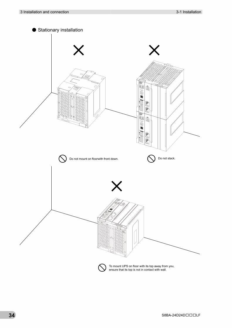
● Stationary installation
Do not stack.Do not mount on floorwith front down.
To mount UPS on floor with its top away from you,ensure that its top is not in contact with wall.
3-1 Installation 3 Installation and connection
S8BA-24D24D□□□LF 35
3
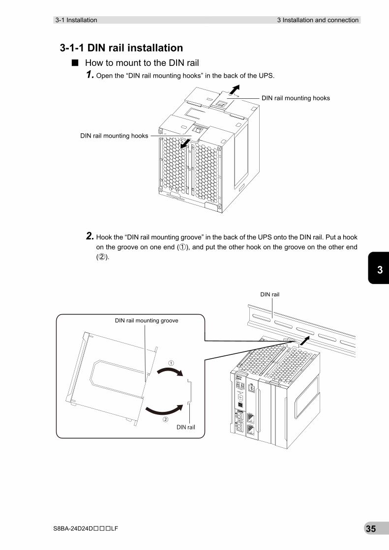
3-1-1 DIN rail installation ■ How to mount to the DIN rail
1. Open the “DIN rail mounting hooks” in the back of the UPS.
2. Hook the “DIN rail mounting groove” in the back of the UPS onto the DIN rail. Put a hook on the groove on one end (①), and put the other hook on the groove on the other end (②).
DIN rail mounting hooks
DIN rail mounting hooks
①
②
DIN rail mounting groove
DIN rail
DIN rail
3 Installation and connection 3-1 Installation
S8BA-24D24D□□□LF 36
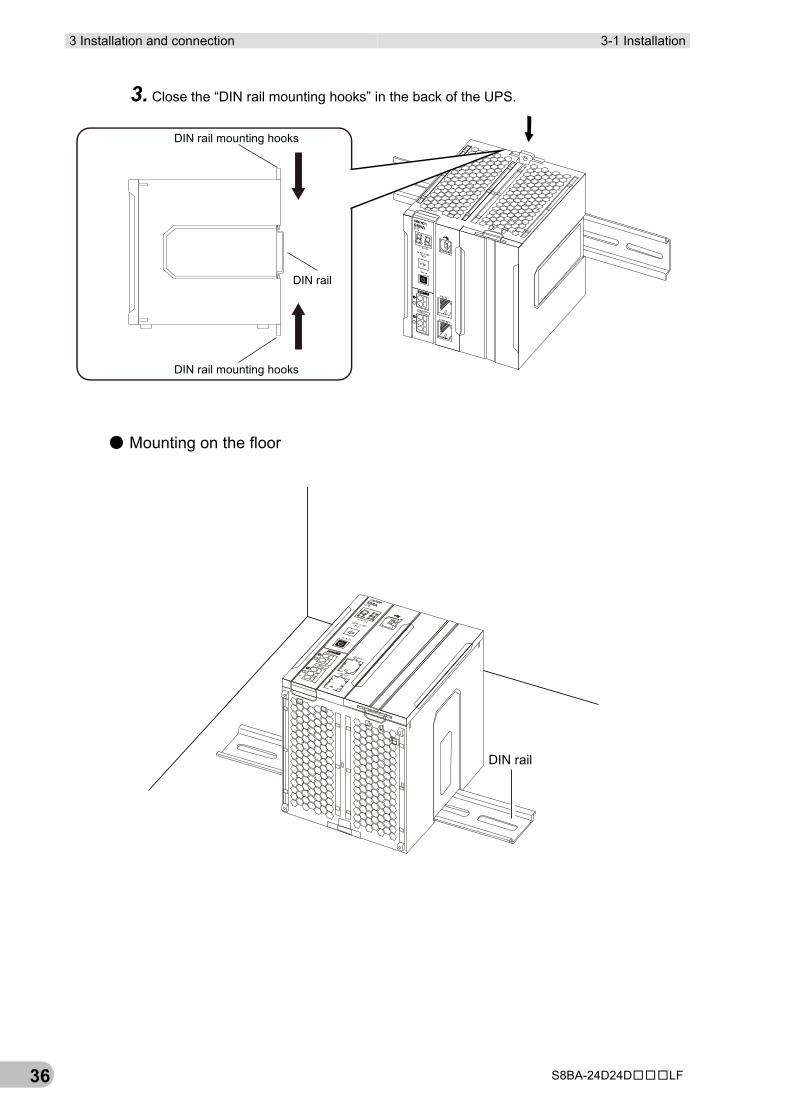
3. Close the “DIN rail mounting hooks” in the back of the UPS.
● Mounting on the floor
DIN rail mounting hooks
DIN rail mounting hooks
DIN rail
DIN rail
3-1 Installation 3 Installation and connection
S8BA-24D24D□□□LF 37
3
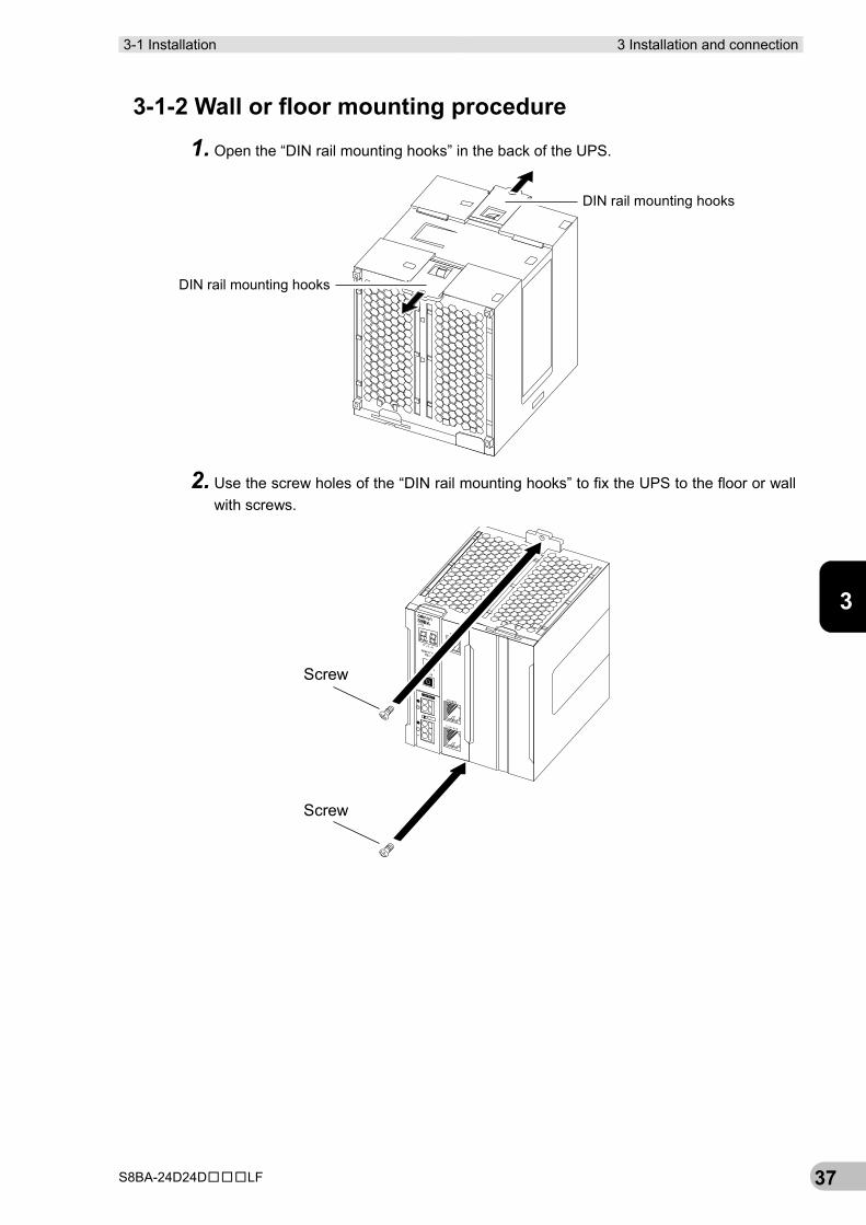
3-1-2 Wall or floor mounting procedure
1. Open the “DIN rail mounting hooks” in the back of the UPS.
2. Use the screw holes of the “DIN rail mounting hooks” to fix the UPS to the floor or wall with screws.
DIN rail mounting hooks
DIN rail mounting hooks
Screw
Screw
3 Installation and connection 3-1 Installation
S8BA-24D24D□□□LF 38
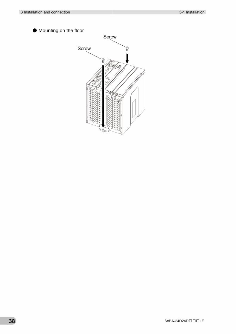
● Mounting on the floor
Screw
Screw
3-1 Installation 3 Installation and connection
S8BA-24D24D□□□LF 39
3
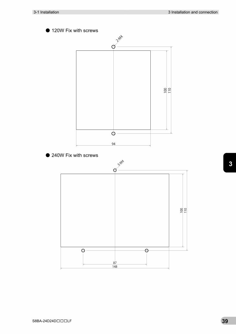
● 120W Fix with screws
● 240W Fix with screws
2-M4
100
110
94
3-M4
100
110
87148
3 Installation and connection 3-1 Installation
S8BA-24D24D□□□LF 40
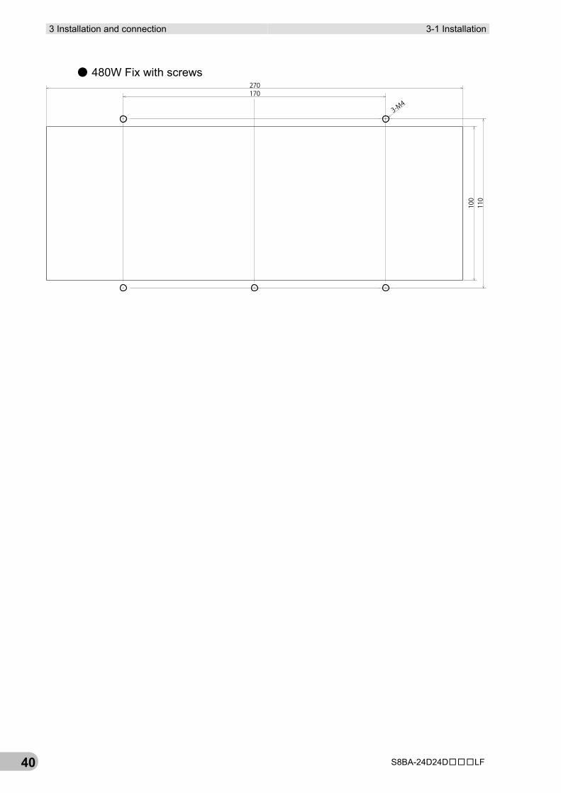
● 480W Fix with screws
3-M4
170270
100
110
3-2 Connection 3 Installation and connection
S8BA-24D24D□□□LF 41
3
3-2 Connection This section describes how to connect the UPS.
For cautions when connecting the UPS, refer to “Caution (for installation and connection)” shown in the “Safety precautions” of the beginning of this manual.
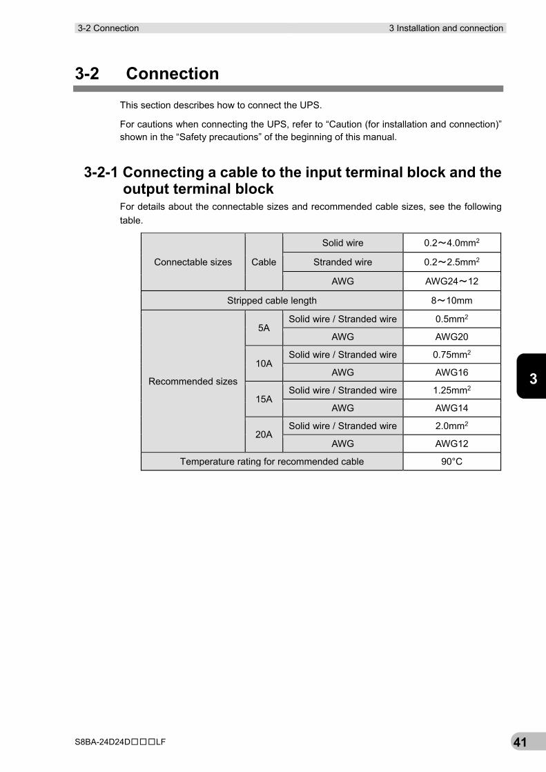
3-2-1 Connecting a cable to the input terminal block and the output terminal block
For details about the connectable sizes and recommended cable sizes, see the following table.
Connectable sizes Cable
Solid wire 0.2~4.0mm2
Stranded wire 0.2~2.5mm2
AWG AWG24~12
Stripped cable length 8~10mm
Recommended sizes
5A Solid wire / Stranded wire 0.5mm2
AWG AWG20
10A Solid wire / Stranded wire 0.75mm2
AWG AWG16
15A Solid wire / Stranded wire 1.25mm2
AWG AWG14
20A Solid wire / Stranded wire 2.0mm2
AWG AWG12
Temperature rating for recommended cable 90°C
3 Installation and connection 3-2 Connection
S8BA-24D24D□□□LF 42
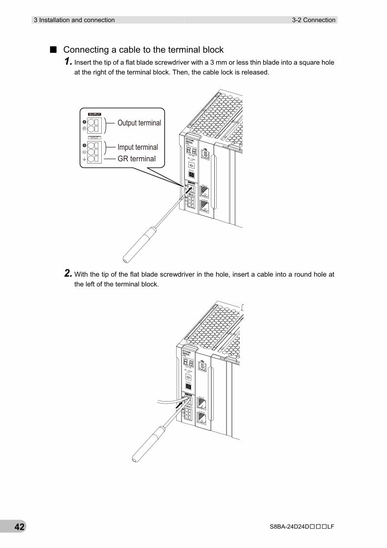
■ Connecting a cable to the terminal block 1. Insert the tip of a flat blade screwdriver with a 3 mm or less thin blade into a square hole
at the right of the terminal block. Then, the cable lock is released.
2. With the tip of the flat blade screwdriver in the hole, insert a cable into a round hole at the left of the terminal block.
Imput terminal
Output terminal
GR terminal
3-2 Connection 3 Installation and connection
S8BA-24D24D□□□LF 43
3
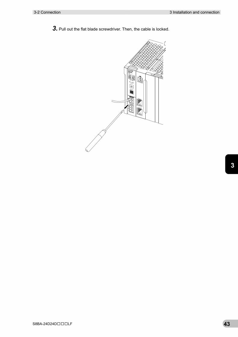
3. Pull out the flat blade screwdriver. Then, the cable is locked.
3 Installation and connection 3-2 Connection
S8BA-24D24D□□□LF 44
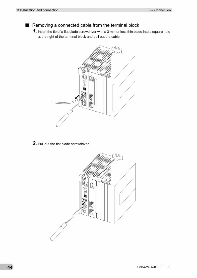
■ Removing a connected cable from the terminal block 1. Insert the tip of a flat blade screwdriver with a 3 mm or less thin blade into a square hole
at the right of the terminal block and pull out the cable.
2. Pull out the flat blade screwdriver.
3-2 Connection 3 Installation and connection
S8BA-24D24D□□□LF 45
3
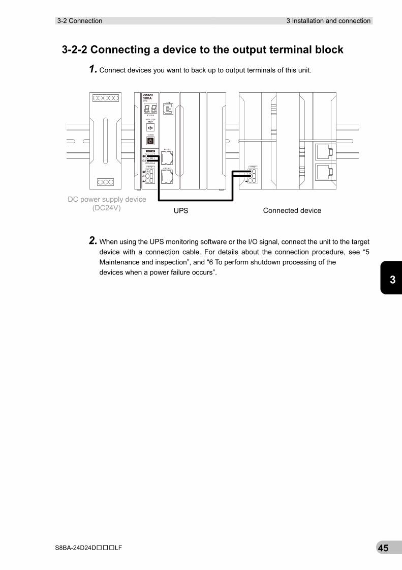
3-2-2 Connecting a device to the output terminal block
1. Connect devices you want to back up to output terminals of this unit.
2. When using the UPS monitoring software or the I/O signal, connect the unit to the target device with a connection cable. For details about the connection procedure, see “5 Maintenance and inspection”, and “6 To perform shutdown processing of the devices when a power failure occurs”.
DC power supply device(DC24V)� Connected deviceUPS
3 Installation and connection 3-2 Connection
S8BA-24D24D□□□LF 46
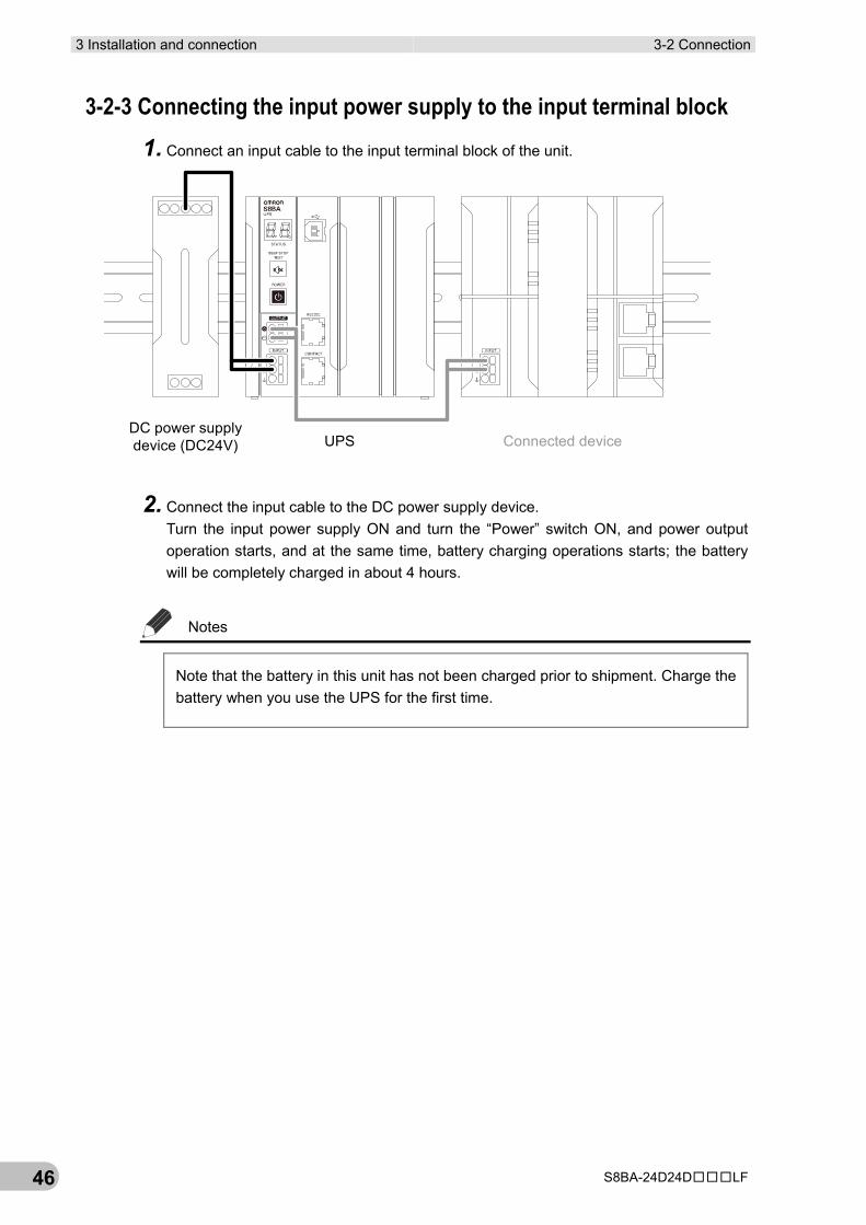
3-2-3 Connecting the input power supply to the input terminal block
1. Connect an input cable to the input terminal block of the unit.
2. Connect the input cable to the DC power supply device. Turn the input power supply ON and turn the “Power” switch ON, and power output operation starts, and at the same time, battery charging operations starts; the battery will be completely charged in about 4 hours.
Notes
Note that the battery in this unit has not been charged prior to shipment. Charge the battery when you use the UPS for the first time.
DC power supplydevice (DC24V) Connected deviceUPS
4-1 The name and function for the operation and display 4 Check and start operation
S8BA-24D24D□□□LF 47
4
4 Check and start operation 4-1 The name and function for the operation and display
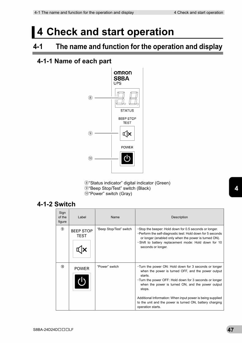
4-1-1 Name of each part
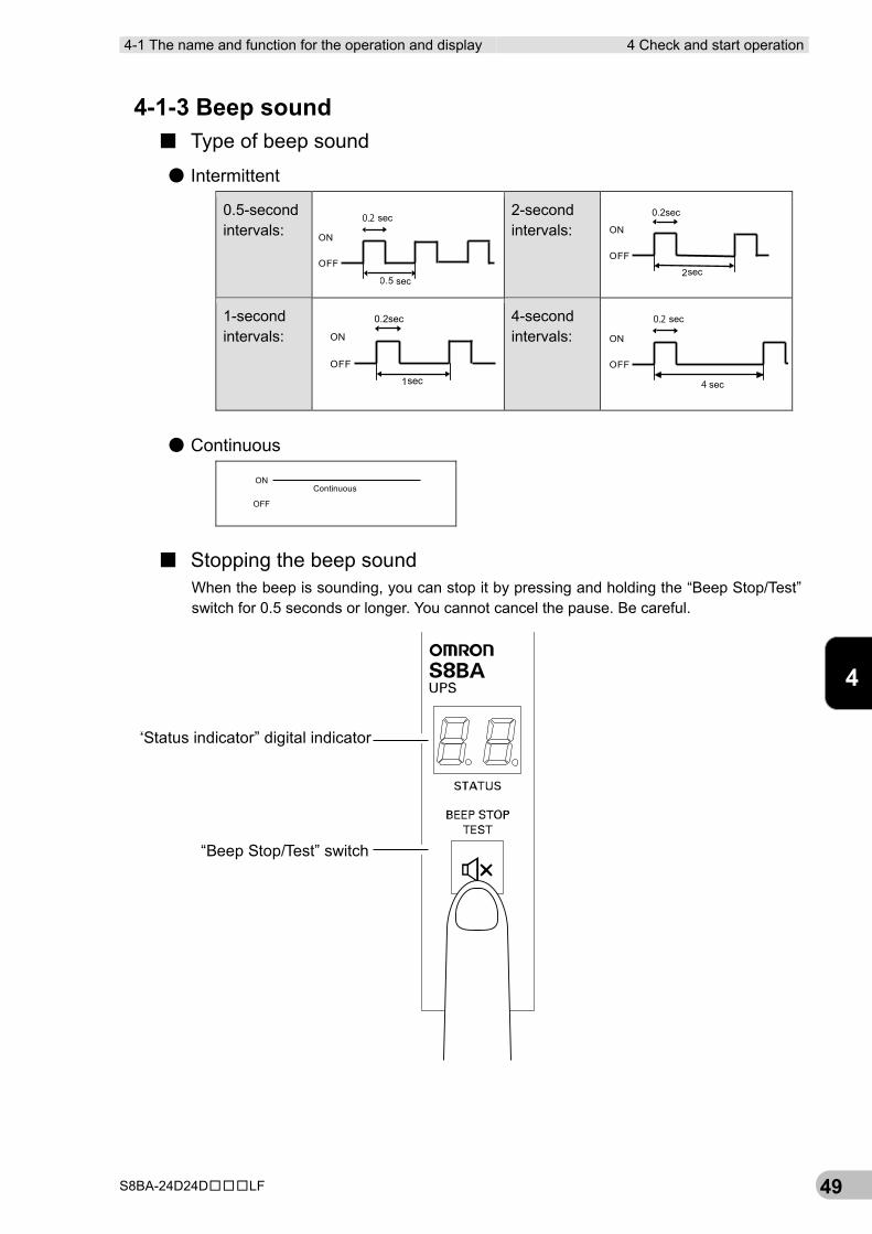
4-1-2 Switch Sign of the figure
Label Name Description
⑨
“Beep Stop/Test” switch ▪Stop the beeper: Hold down for 0.5 seconds or longer. ▪Perform the self-diagnostic test: Hold down for 5 seconds
or longer (enabled only when the power is turned ON). ▪Shift to battery replacement mode: Hold down for 10
seconds or longer.
⑩
“Power” switch ▪Turn the power ON: Hold down for 3 seconds or longer when the power is turned OFF, and the power output starts.
▪Turn the power OFF: Hold down for 3 seconds or longer when the power is turned ON, and the power output stops.
Additional Information: When input power is being supplied to the unit and the power is turned ON, battery charging operation starts.
⑧
⑨
⑩
⑧“Status indicator” digital indicator (Green)⑨“Beep Stop/Test” switch (Black)⑩“Power” switch (Gray)

4 Check and start operation 4-1 The name and function for the operation and display
S8BA-24D24D□□□LF 48
4-1 The name and function for the operation and display 4 Check and start operation
S8BA-24D24D□□□LF 49
4
4-1-3 Beep sound ■ Type of beep sound
● Intermittent
0.5-second intervals:
2-second intervals:
1-second intervals:
4-second intervals:
● Continuous
■ Stopping the beep sound When the beep is sounding, you can stop it by pressing and holding the “Beep Stop/Test” switch for 0.5 seconds or longer. You cannot cancel the pause. Be careful.
ON
OFF
2sec
0.2sec
ON
OFF
1sec
0.2sec
ON
OFF
0.2 sec
4 sec
ON
OFF
Continuous
“Status indicator” digital indicator
“Beep Stop/Test” switch
ON
OFF
0.5 sec
0.2 sec
4 Check and start operation 4-2 Start and stop procedures and basic operation
S8BA-24D24D□□□LF 50
4-2 Start and stop procedures and basic operation
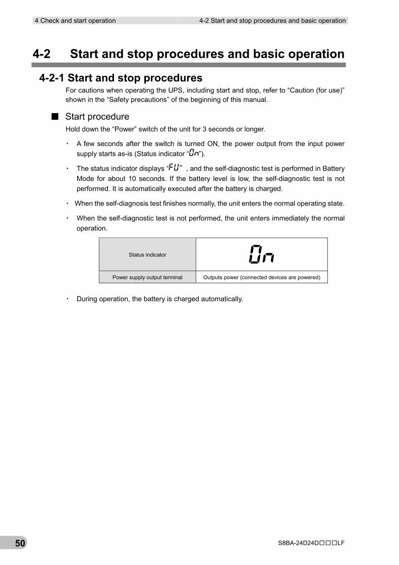
4-2-1 Start and stop procedures For cautions when operating the UPS, including start and stop, refer to “Caution (for use)” shown in the “Safety precautions” of the beginning of this manual.
■ Start procedure Hold down the “Power” switch of the unit for 3 seconds or longer.
▪ A few seconds after the switch is turned ON, the power output from the input power supply starts as-is (Status indicator “ ”).
▪ The status indicator displays “ ”, and the self-diagnostic test is performed in Battery Mode for about 10 seconds. If the battery level is low, the self-diagnostic test is not performed. It is automatically executed after the battery is charged.
▪ When the self-diagnosis test finishes normally, the unit enters the normal operating state.
▪ When the self-diagnostic test is not performed, the unit enters immediately the normal operation.
▪ During operation, the battery is charged automatically.
Status indicator
Power supply output terminal Outputs power (connected devices are powered)
4-2 Start and stop procedures and basic operation 4 Check and start operation
S8BA-24D24D□□□LF 51
4
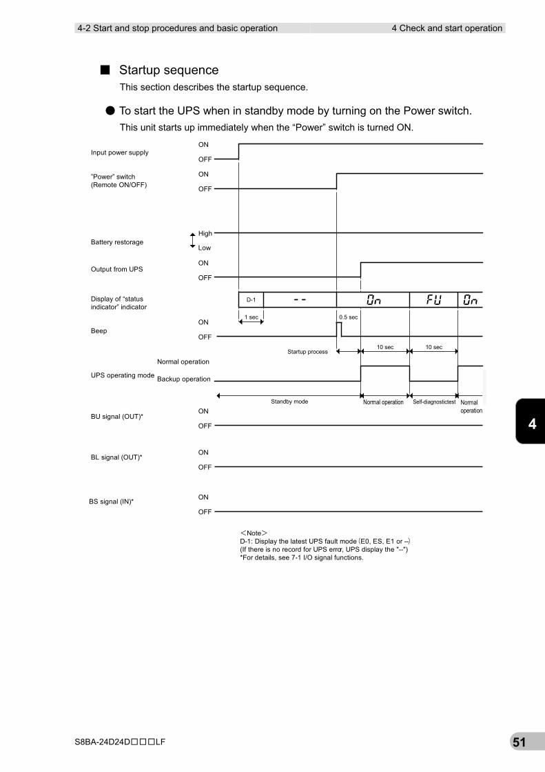
■ Startup sequence This section describes the startup sequence.
● To start the UPS when in standby mode by turning on the Power switch. This unit starts up immediately when the “Power” switch is turned ON.
Standby mode Normal operation
Startup process
ON
OFF
ON
OFF
High
Low
ON
OFF
ON
OFF
0.5 sec
ON
OFF
ON
OFF
ON
OFF
Normal operation
Backup operation
Self-diagnostictest Normaloperation
10 sec 10 sec
1 sec
D-1
Battery restorage
Output from UPS
Display of “statusindicator” indicator
Beep
UPS operating mode
”Power” switch(Remote ON/OFF)
Input power supply
BL signal (OUT)*
BS signal (IN)*
BU signal (OUT)*
<Note>D-1: Display the latest UPS fault mode(E0, ES, E1 or --)(If there is no record for UPS error, UPS display the "--")*For details, see 7-1 I/O signal functions.
4 Check and start operation 4-2 Start and stop procedures and basic operation
S8BA-24D24D□□□LF 52
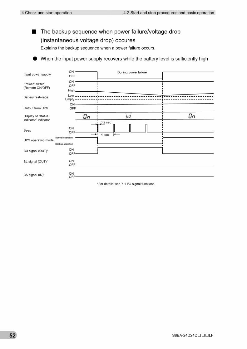
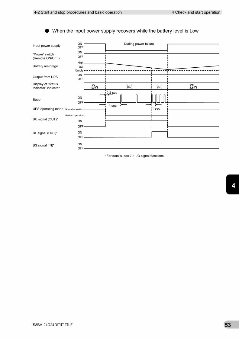
■ The backup sequence when power failure/voltage drop (instantaneous voltage drop) occures Explains the backup sequence when a power failure occurs.
● When the input power supply recovers while the battery level is sufficiently high
0.2 sec
4 sec
*For details, see 7-1 I/O signal functions.
ON
ON
ON
OFF
OFF
OFF
OFF
OFF
OFF
Durling power failure
HighLow
Empty
OFF
ON
ON
ON
ON
Battery restorage
Output from UPS
Display of “statusindicator” indicator
Beep
UPS operating mode
“Power” switch(Remote ON/OFF)
Input power supply
BL signal (OUT)*
BS signal (IN)*
BU signal (OUT)*
Normal operation
Backup operation
4-2 Start and stop procedures and basic operation 4 Check and start operation
S8BA-24D24D□□□LF 53
4
● When the input power supply recovers while the battery level is Low
Durling power failureON
ON
ON
OFF
OFF
OFF
OFF
OFF
OFF
HighLow
Empty
OFF
ON
ON
ON
ON
*For details, see 7-1 I/O signal functions.
Battery restorage
Output from UPS
Display of “statusindicator” indicator
UPS operating mode
“Power” switch(Remote ON/OFF)
Input power supply
BL signal (OUT)*
BS signal (IN)*
BU signal (OUT)*
Beep
Normal operation
Backup operation
0.2 sec
4 sec1 sec
4 Check and start operation 4-2 Start and stop procedures and basic operation
S8BA-24D24D□□□LF 54
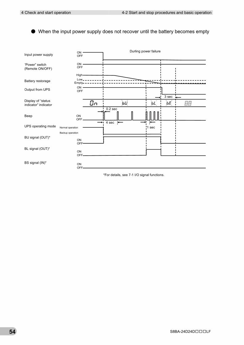
● When the input power supply does not recover until the battery becomes empty
Durling power failure
*For details, see 7-1 I/O signal functions.
ON
ON
ON
OFF
OFF
OFF
OFF
OFF
OFF
HighLow
Empty
OFF
ON
ON
ON
ON
Battery restorage
Output from UPS
Display of “statusindicator” indicator
Beep
UPS operating mode
“Power” switch(Remote ON/OFF)
Input power supply
BL signal (OUT)*
BS signal (IN)*
BU signal (OUT)*
Normal operation
Backup operation
0.2 sec
4 sec1 sec
3 sec
4-2 Start and stop procedures and basic operation 4 Check and start operation
S8BA-24D24D□□□LF 55
4
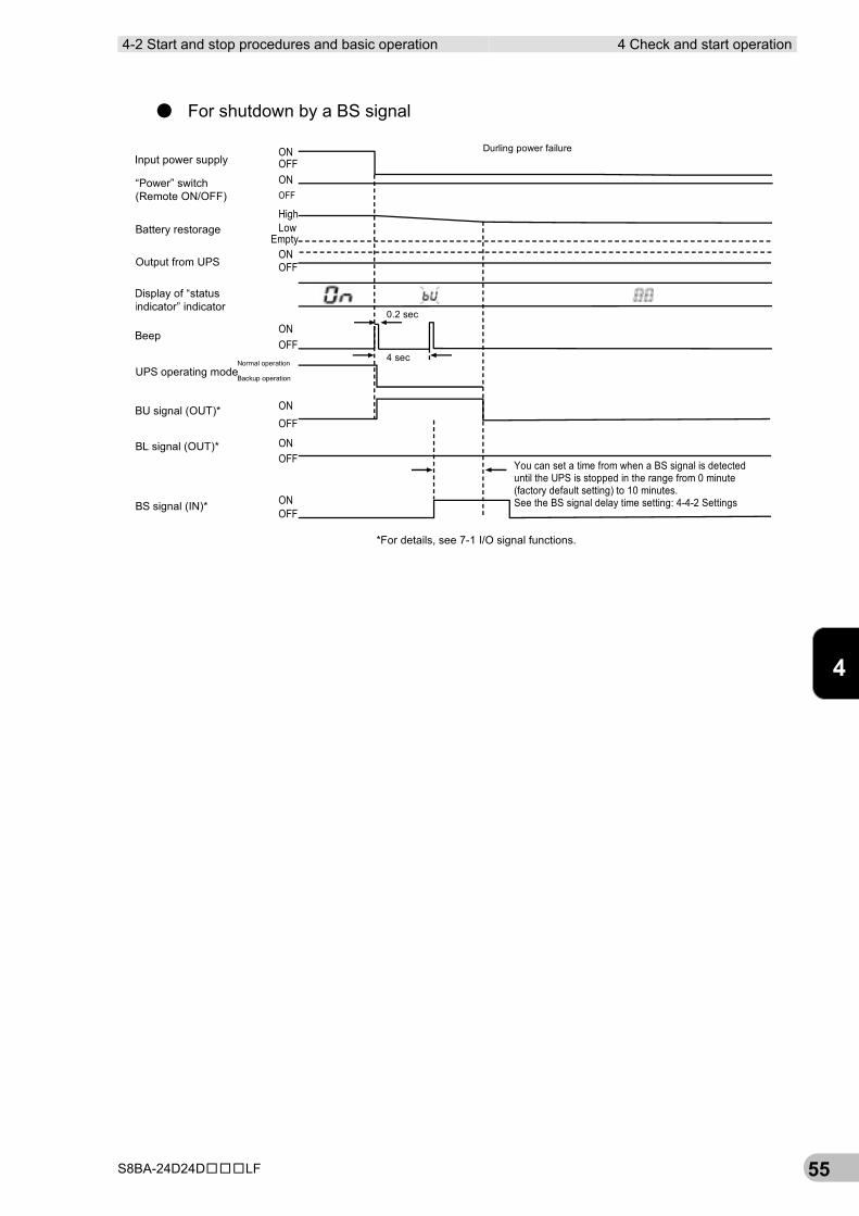
● For shutdown by a BS signal
Durling power failureON
ON
ON
OFF
OFF
OFF
OFF
OFF
OFF
HighLow
Empty
OFF
ON
ON
ON
ON
Battery restorage
Output from UPS
Display of “statusindicator” indicator
Beep
UPS operating mode
“Power” switch(Remote ON/OFF)
Input power supply
BL signal (OUT)*
BS signal (IN)*
BU signal (OUT)*
Normal operation
Backup operation
0.2 sec
4 sec
*For details, see 7-1 I/O signal functions.
You can set a time from when a BS signal is detecteduntil the UPS is stopped in the range from 0 minute(factory default setting) to 10 minutes.See the BS signal delay time setting: 4-4-2 Settings
4 Check and start operation 4-2 Start and stop procedures and basic operation
S8BA-24D24D□□□LF 56
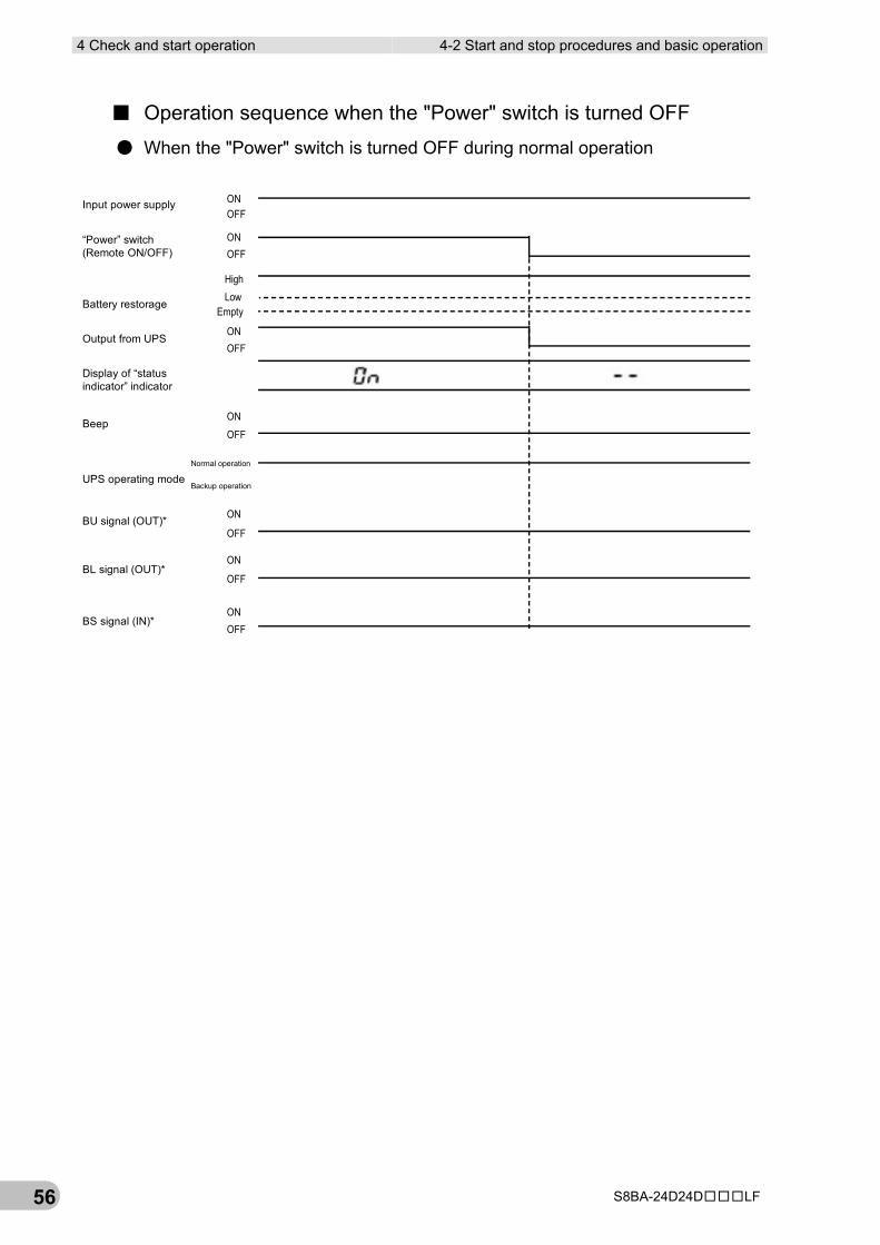
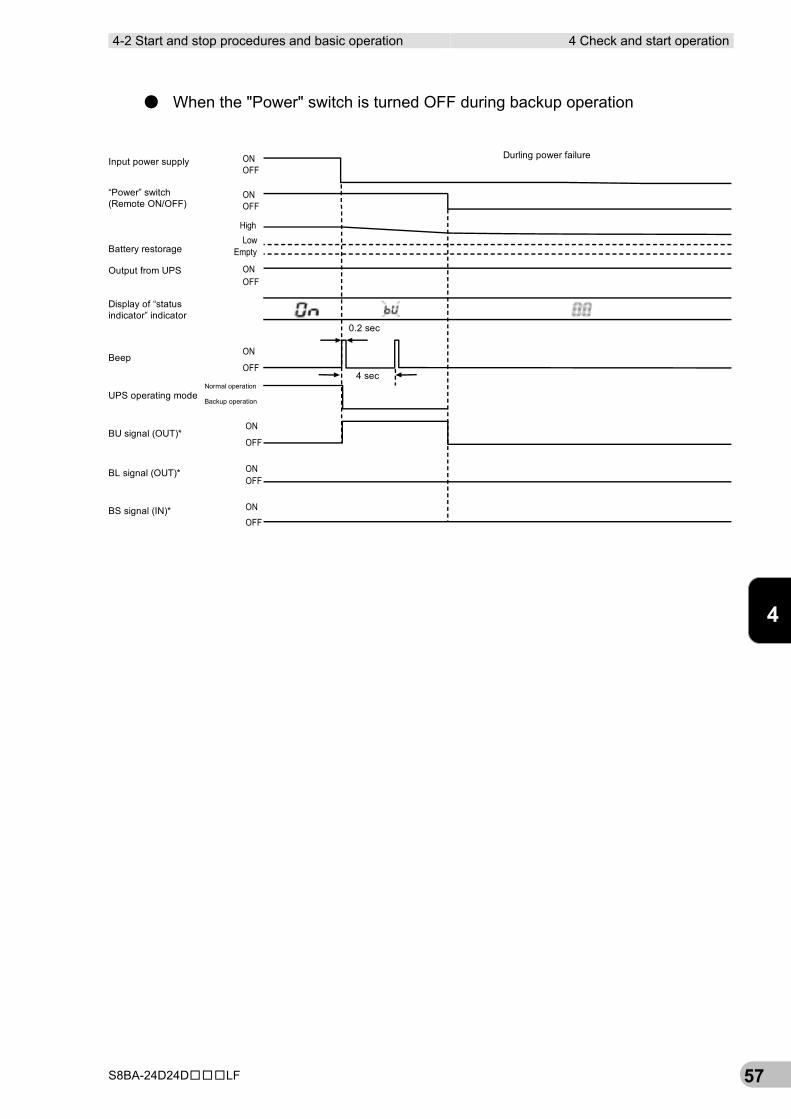
■ Operation sequence when the "Power" switch is turned OFF
● When the "Power" switch is turned OFF during normal operation
ON
ON
ON
OFF
OFF
OFF
OFF
OFF
OFF
HighLow
Empty
OFF
ON
ON
ON
ON
Battery restorage
Output from UPS
Display of “statusindicator” indicator
Beep
UPS operating mode
“Power” switch(Remote ON/OFF)
Input power supply
BL signal (OUT)*
BS signal (IN)*
BU signal (OUT)*
Normal operation
Backup operation
4-2 Start and stop procedures and basic operation 4 Check and start operation
S8BA-24D24D□□□LF 57
4
● When the "Power" switch is turned OFF during backup operation
ON
ON
ON
OFF
OFF
OFF
OFF
OFF
HighLow
Empty
OFF
ON
ON
ON
ON
OFF
Durling power failure
0.2 sec
4 sec
Battery restorage
Output from UPS
Display of “statusindicator” indicator
Beep
UPS operating mode
“Power” switch(Remote ON/OFF)
Input power supply
BL signal (OUT)*
BS signal (IN)*
BU signal (OUT)*
Normal operation
Backup operation
4 Check and start operation 4-2 Start and stop procedures and basic operation
S8BA-24D24D□□□LF 58
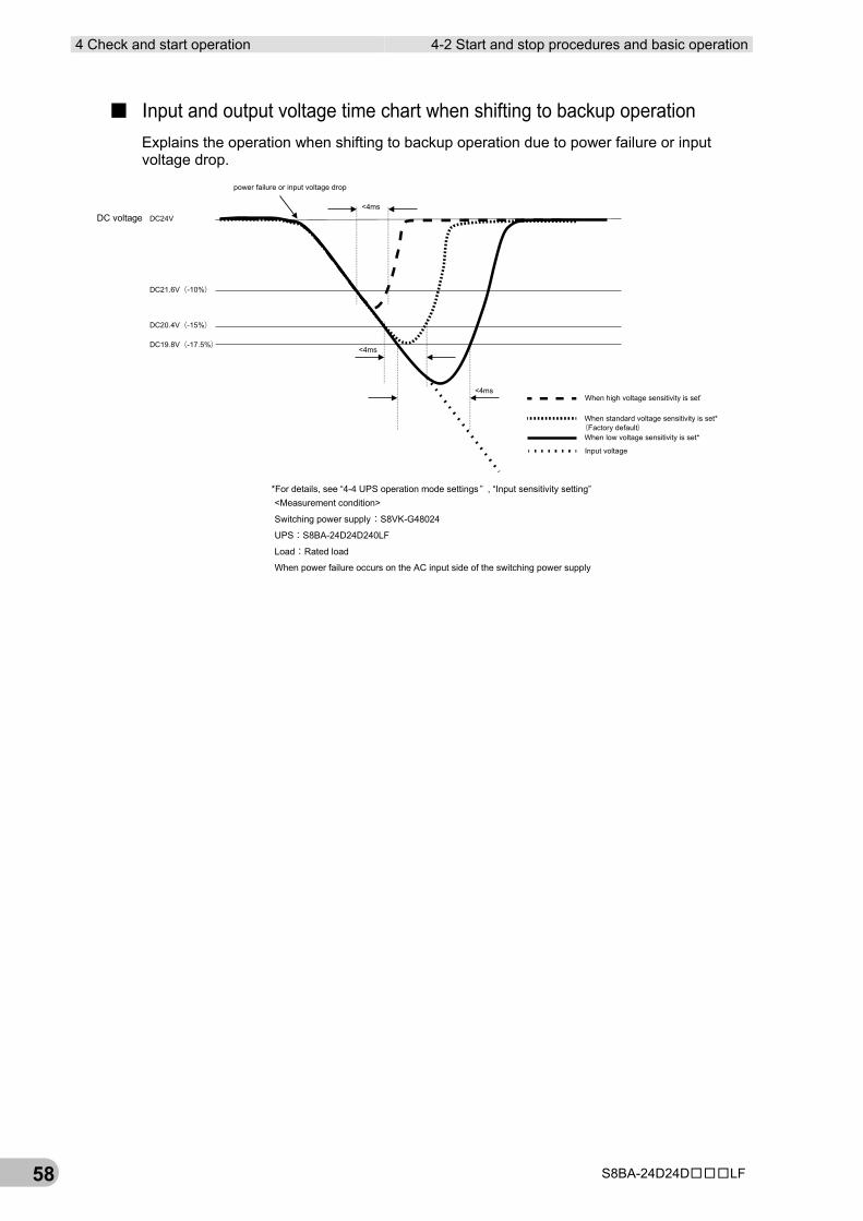
■ Input and output voltage time chart when shifting to backup operation Explains the operation when shifting to backup operation due to power failure or input voltage drop.
<4ms
<4msWhen high voltage sensitivity is set*
When standard voltage sensitivity is set*
When low voltage sensitivity is set*
Input voltage
<4ms
power failure or input voltage drop
DC24V
DC21.6V(-10%)
DC20.4V(-15%)
DC19.8V(-17.5%)
DC voltage
(Factory default)
<Measurement condition>
Switching power supply:S8VK-G48024
UPS:S8BA-24D24D240LF
Load:Rated load
When power failure occurs on the AC input side of the switching power supply
*For details, see “4-4 UPS operation mode settings ” , “Input sensitivity setting”
4-2 Start and stop procedures and basic operation 4 Check and start operation
S8BA-24D24D□□□LF 59
4
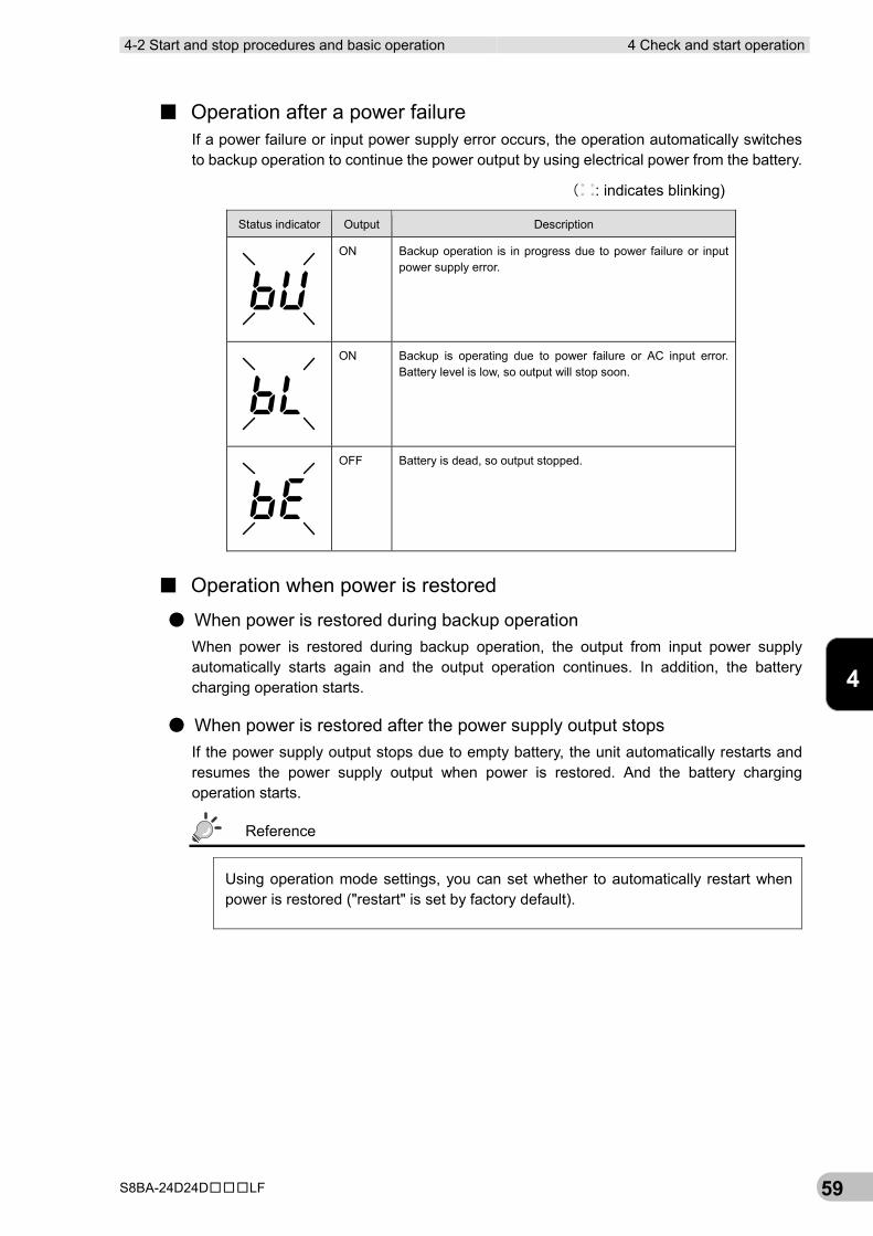
■ Operation after a power failure If a power failure or input power supply error occurs, the operation automatically switches to backup operation to continue the power output by using electrical power from the battery.
( : indicates blinking)
Status indicator Output Description
ON Backup operation is in progress due to power failure or input power supply error.
ON Backup is operating due to power failure or AC input error. Battery level is low, so output will stop soon.
OFF Battery is dead, so output stopped.
■ Operation when power is restored
● When power is restored during backup operation When power is restored during backup operation, the output from input power supply automatically starts again and the output operation continues. In addition, the battery charging operation starts.
● When power is restored after the power supply output stops If the power supply output stops due to empty battery, the unit automatically restarts and resumes the power supply output when power is restored. And the battery charging operation starts.
Reference
Using operation mode settings, you can set whether to automatically restart when power is restored ("restart" is set by factory default).
4 Check and start operation 4-3 Interpreting beeps and displays
S8BA-24D24D□□□LF 60
■ Operation when stopping Hold down the “Power” switch of the unit for 3 seconds or longer, and the power is turned OFF and the output stops.
Reference
When the “Power” switch is turned OFF, the battery charging operation stops.
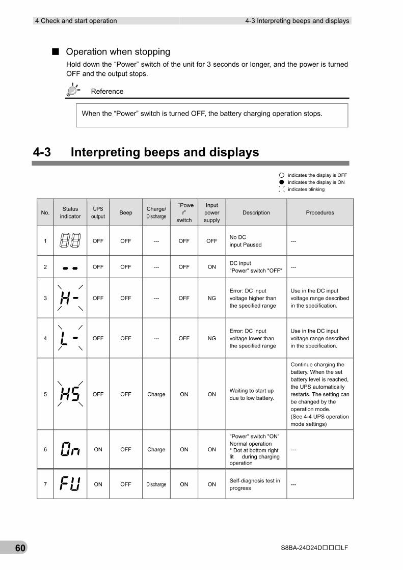
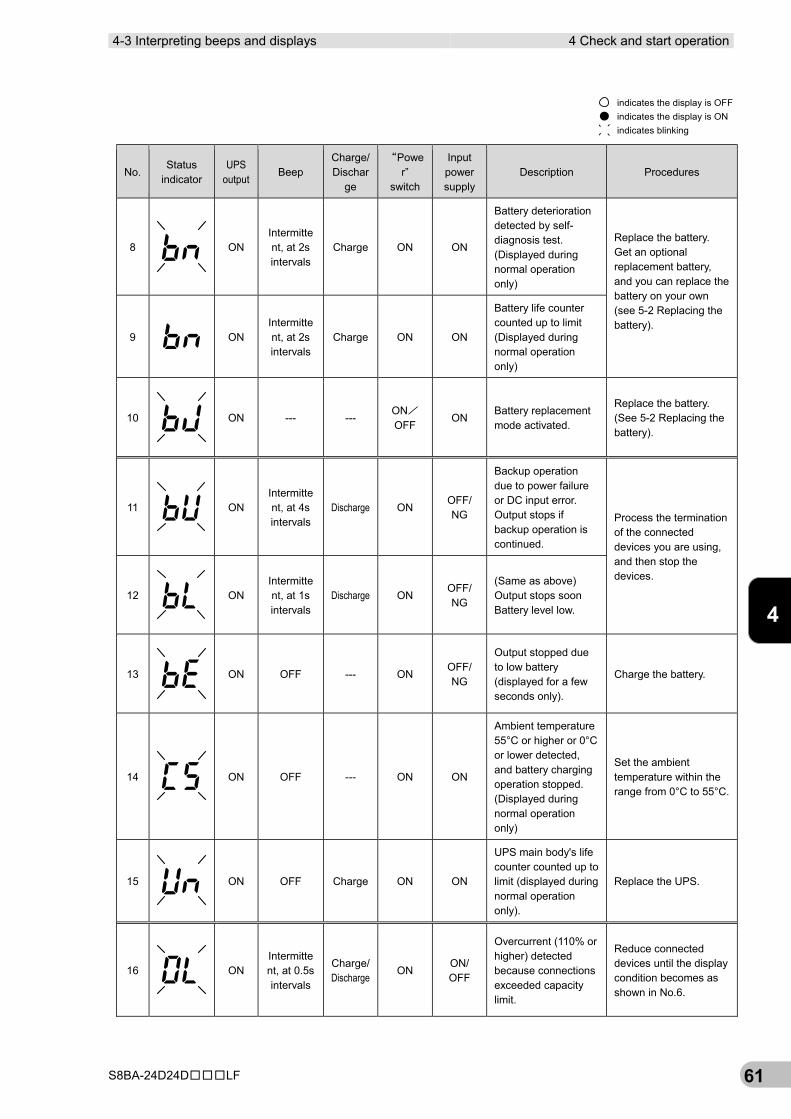
4-3 Interpreting beeps and displays
No. Status
indicator UPS
output Beep
Charge/ Discharge
“Power”
switch
Input power supply
Description Procedures
1
OFF OFF --- OFF OFF No DC input Paused
---
2 OFF OFF --- OFF ON DC input "Power" switch "OFF"
---
3
OFF OFF --- OFF NG
Error: DC input voltage higher than the specified range
Use in the DC input voltage range described in the specification.
4
OFF OFF --- OFF NG
Error: DC input voltage lower than the specified range
Use in the DC input voltage range described in the specification.
5
OFF OFF Charge ON ON
Waiting to start up due to low battery.
Continue charging the battery. When the set battery level is reached, the UPS automatically restarts. The setting can be changed by the operation mode. (See 4-4 UPS operation mode settings)
6
ON OFF Charge ON ON
"Power" switch "ON" Normal operation * Dot at bottom right lit during charging operation
---
7
ON OFF Discharge ON ON Self-diagnosis test in progress
---
indicates blinkingindicates the display is ONindicates the display is OFF
4-3 Interpreting beeps and displays 4 Check and start operation
S8BA-24D24D□□□LF 61
4
No. Status
indicator UPS
output Beep
Charge/ Dischar
ge
“Power”
switch
Input power supply
Description Procedures
8
ON
Intermittent, at 2s intervals
Charge ON ON
Battery deterioration detected by self-diagnosis test. (Displayed during normal operation only)
Replace the battery. Get an optional replacement battery, and you can replace the battery on your own (see 5-2 Replacing the battery). 9 ON
Intermittent, at 2s intervals
Charge ON ON
Battery life counter counted up to limit (Displayed during normal operation only)
10
ON --- ---
ON/ OFF
ON Battery replacement mode activated.
Replace the battery. (See 5-2 Replacing the battery).
11
ON
Intermittent, at 4s intervals
Discharge ON OFF/ NG
Backup operation due to power failure or DC input error. Output stops if backup operation is continued.
Process the termination of the connected devices you are using, and then stop the devices.
12
ON
Intermittent, at 1s intervals
Discharge ON OFF/ NG
(Same as above) Output stops soon Battery level low.
13
ON OFF --- ON
OFF/ NG
Output stopped due to low battery (displayed for a few seconds only).
Charge the battery.
14
ON OFF --- ON ON
Ambient temperature 55°C or higher or 0°C or lower detected, and battery charging operation stopped. (Displayed during normal operation only)
Set the ambient temperature within the range from 0°C to 55°C.
15
ON OFF Charge ON ON
UPS main body's life counter counted up to limit (displayed during normal operation only).
Replace the UPS.
16
ON
Intermittent, at 0.5s intervals
Charge/ Discharge
ON ON/ OFF
Overcurrent (110% or higher) detected because connections exceeded capacity limit.
Reduce connected devices until the display condition becomes as shown in No.6.
indicates blinkingindicates the display is ONindicates the display is OFF
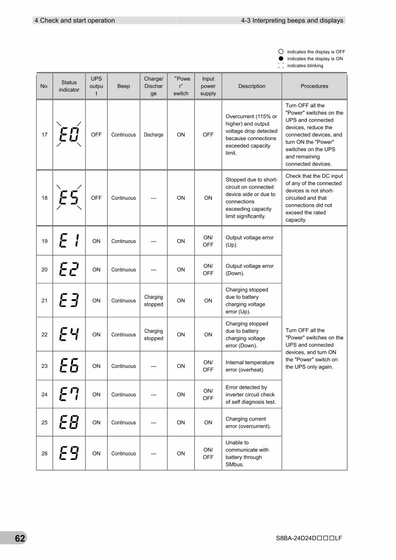
4 Check and start operation 4-3 Interpreting beeps and displays
S8BA-24D24D□□□LF 62
No. Status
indicator
UPS outpu
t Beep
Charge/ Dischar
ge
“Power”
switch
Input power supply
Description Procedures
17
OFF Continuous Discharge ON OFF
Overcurrent (115% or higher) and output voltage drop detected because connections exceeded capacity limit.
Turn OFF all the "Power" switches on the UPS and connected devices, reduce the connected devices, and turn ON the "Power" switches on the UPS and remaining connected devices.
18
OFF Continuous --- ON ON
Stopped due to short-circuit on connected device side or due to connections exceeding capacity limit significantly.
Check that the DC input of any of the connected devices is not short-circuited and that connections did not exceed the rated capacity.
19
ON Continuous --- ON ON/ OFF
Output voltage error (Up).
Turn OFF all the "Power" switches on the UPS and connected devices, and turn ON the "Power" switch on the UPS only again.
20
ON Continuous --- ON ON/ OFF
Output voltage error (Down).
21
ON Continuous Charging stopped
ON ON
Charging stopped due to battery charging voltage error (Up).
22
ON Continuous Charging stopped
ON ON
Charging stopped due to battery charging voltage error (Down).
23
ON Continuous --- ON ON/ OFF
Internal temperature error (overheat).
24
ON Continuous --- ON ON/ OFF
Error detected by inverter circuit check of self diagnosis test.
25
ON Continuous --- ON ON Charging current error (overcurrent).
26
ON Continuous --- ON ON/ OFF
Unable to communicate with battery through SMbus.
indicates blinkingindicates the display is ONindicates the display is OFF
4-4 UPS operation mode settings 4 Check and start operation
S8BA-24D24D□□□LF 63
4
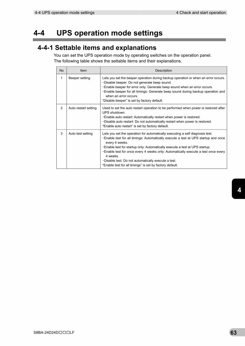
4-4 UPS operation mode settings
4-4-1 Settable items and explanations You can set the UPS operation mode by operating switches on the operation panel. The following table shows the settable items and their explanations.
No Item Description
1 Beeper setting Lets you set the beeper operation during backup operation or when an error occurs. ▪Disable beeper: Do not generate beep sound. ▪Enable beeper for error only: Generate beep sound when an error occurs. ▪Enable beeper for all timings: Generate beep sound during backup operation and
when an error occurs. “Disable beeper” is set by factory default.
2 Auto restart setting Used to set the auto restart operation to be performed when power is restored after UPS shutdown. ▪Enable auto restart: Automatically restart when power is restored. ▪Disable auto restart: Do not automatically restart when power is restored. “Enable auto restart” is set by factory default.
3 Auto test setting Lets you set the operation for automatically executing a self diagnosis test. ▪Enable test for all timings: Automatically execute a test at UPS startup and once
every 4 weeks. ▪Enable test for startup only: Automatically execute a test at UPS startup. ▪Enable test for once every 4 weeks only: Automatically execute a test once every
4 weeks. ▪Disable test: Do not automatically execute a test. “Enable test for all timings” is set by factory default.
4 Check and start operation 4-4 UPS operation mode settings
S8BA-24D24D□□□LF 64
No Item Description
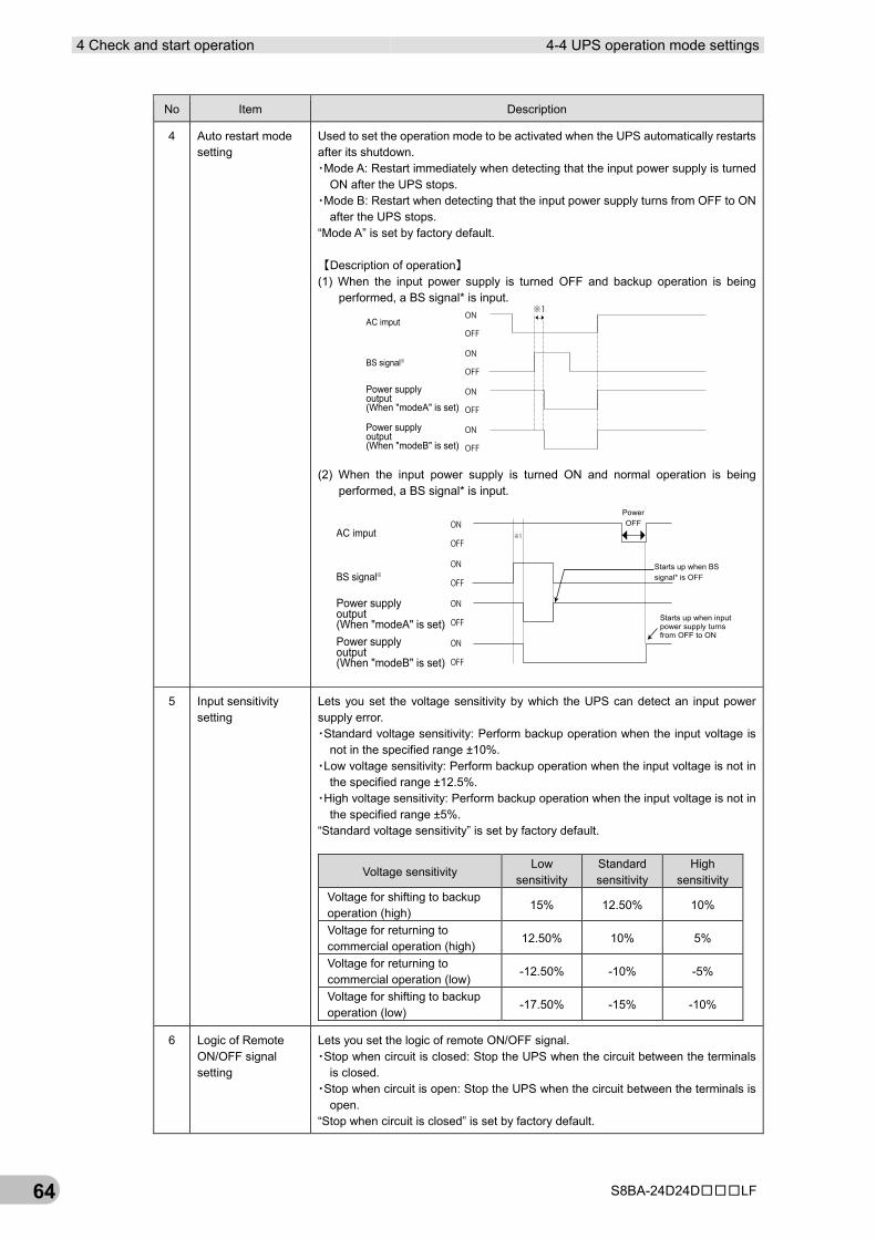
4 Auto restart mode setting
Used to set the operation mode to be activated when the UPS automatically restarts after its shutdown. ▪Mode A: Restart immediately when detecting that the input power supply is turned
ON after the UPS stops. ▪Mode B: Restart when detecting that the input power supply turns from OFF to ON
after the UPS stops. “Mode A” is set by factory default. 【Description of operation】 (1) When the input power supply is turned OFF and backup operation is being
performed, a BS signal* is input.
(2) When the input power supply is turned ON and normal operation is being
performed, a BS signal* is input.
5 Input sensitivity setting
Lets you set the voltage sensitivity by which the UPS can detect an input power supply error. ▪Standard voltage sensitivity: Perform backup operation when the input voltage is
not in the specified range ±10%. ▪Low voltage sensitivity: Perform backup operation when the input voltage is not in
the specified range ±12.5%. ▪High voltage sensitivity: Perform backup operation when the input voltage is not in
the specified range ±5%. “Standard voltage sensitivity” is set by factory default.
Voltage sensitivity Low
sensitivity Standard sensitivity
High sensitivity
Voltage for shifting to backup operation (high)
15% 12.50% 10%
Voltage for returning to commercial operation (high)
12.50% 10% 5%
Voltage for returning to commercial operation (low)
-12.50% -10% -5%
Voltage for shifting to backup operation (low)
-17.50% -15% -10%
6 Logic of Remote ON/OFF signal setting
Lets you set the logic of remote ON/OFF signal. ▪Stop when circuit is closed: Stop the UPS when the circuit between the terminals
is closed. ▪Stop when circuit is open: Stop the UPS when the circuit between the terminals is
open. “Stop when circuit is closed” is set by factory default.
ON
OFF
ON
OFF
ON
OFF
ON
OFF
※1AC imput
BS signal※
Power supplyoutput(When "modeB" is set)
Power supplyoutput(When "modeA" is set)
※1
ON
OFF
ON
OFF
ON
OFF
ON
OFF
PowerOFF
Starts up when BSsignal* is OFF
Starts up when inputpower supply turnsfrom OFF to ON
AC imput
BS signal※
Power supplyoutput(When "modeB" is set)
Power supplyoutput(When "modeA" is set)
4-4 UPS operation mode settings 4 Check and start operation
S8BA-24D24D□□□LF 65
4
No Item Description
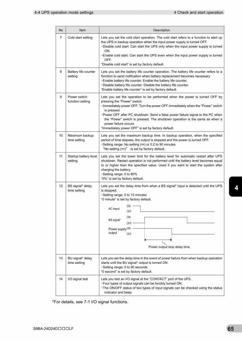
7 Cold start setting Lets you set the cold start operation. The cold start refers to a function to start up the UPS in backup operation when the input power supply is turned OFF. ▪Disable cold start: Can start the UPS only when the input power supply is turned
ON. ▪Enable cold start: Can start the UPS even when the input power supply is turned
OFF. “Disable cold start” is set by factory default.
8 Battery life counter setting
Lets you set the battery life counter operation. The battery life counter refers to a function to send notification when battery replacement becomes necessary. ▪Enable battery life counter: Enable the battery life counter. ▪Disable battery life counter: Disable the battery life counter. “Enable battery life counter” is set by factory default.
9 Power switch function setting
Lets you set the operation to be performed when the power is turned OFF by pressing the “Power” switch. ▪Immediately power OFF: Turn the power OFF immediately when the “Power” switch
is pressed. ▪Power OFF after PC shutdown: Send a false power failure signal to the PC when
the “Power” switch is pressed. The shutdown operation is the same as when a power failure occurs.
“Immediately power OFF” is set by factory default.
10 Maximum backup time setting
Lets you set the maximum backup time. In backup operation, when the specified period of time elapses, the output is stopped and the power is turned OFF. ▪Setting range: No setting (∞) or 0.2 to 90 minutes “No setting (∞)” is set by factory default.
11 Startup battery level setting
Lets you set the lower limit for the battery level for automatic restart after UPS shutdown. Restart operation is not performed until the battery level becomes equal to or higher than the specified value. Used if you want to start the system after charging the battery. ▪Setting range: 0 to 90% “0%” is set by factory default.
12 BS signal* delay time setting
Lets you set the delay time from when a BS signal* input is detected until the UPS is stopped. ▪Setting range: 0 to 10 minutes “0 minute” is set by factory default.
13 BU signal* delay time setting
Lets you set the delay time in the event of power failure from when backup operation starts until the BU signal* output is turned ON. ▪Setting range: 0 to 90 seconds “0 second” is set by factory default.
14 I/O signal test Lets you test an I/O signal at the “CONTACT” port of the UPS. ▪Four types of output signals can be forcibly turned ON. ▪The ON/OFF status of two types of input signals can be checked using the status
indicator and beep.
*For details, see 7-1 I/O signal functions.
ON
ON
ON
OFF
OFF
OFF
AC imput
BS signal※
Power supplyoutput
Power output stop delay time
4 Check and start operation 4-4 UPS operation mode settings
S8BA-24D24D□□□LF 66
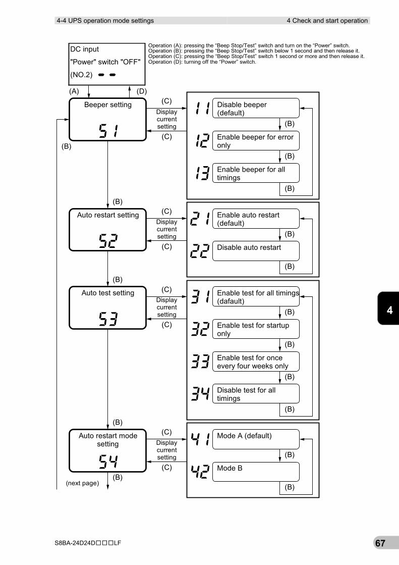
4-4-2 Settings With the “Beep Stop/Test” switch held down, turn the “Power” switch to move to the UPS operation mode setting.
*While the setting mode is active, the output power supply is turned OFF.
4-4 UPS operation mode settings 4 Check and start operation
S8BA-24D24D□□□LF 67
4
(B)
(B)
(B)
(B)
(B)
(B)
(B)
(B)
(C)
(C)(A) (D)
(C)
(C)(B)
(B)
(B)
(C)
(C)
(C)
(C)(B)
(B)
(B)
(B)
(B)
Enable beeper for erroronly
Disable beeper(default)
Disable auto restart
Enable test for all timings(dafault)
Enable test for startuponly
Enable auto restart(default)
Enable test for onceevery four weeks only
Disable test for alltimings
Mode A (default)
Mode B
Auto restart settingDisplaycurrentsetting
Enable beeper for alltimings
Beeper settingDisplaycurrentsetting
Displaycurrentsetting
Auto test setting
Displaycurrentsetting
Auto restart modesetting
(next page)
DC input
"Power" switch "OFF"�
(NO.2)
Operation (A): pressing the “Beep Stop/Test” switch and turn on the “Power” switch.Operation (B): pressing the “Beep Stop/Test” switch below 1 second and then release it.Operation (C): pressing the “Beep Stop/Test” switch 1 second or more and then release it.Operation (D): turning off the “Power” switch.
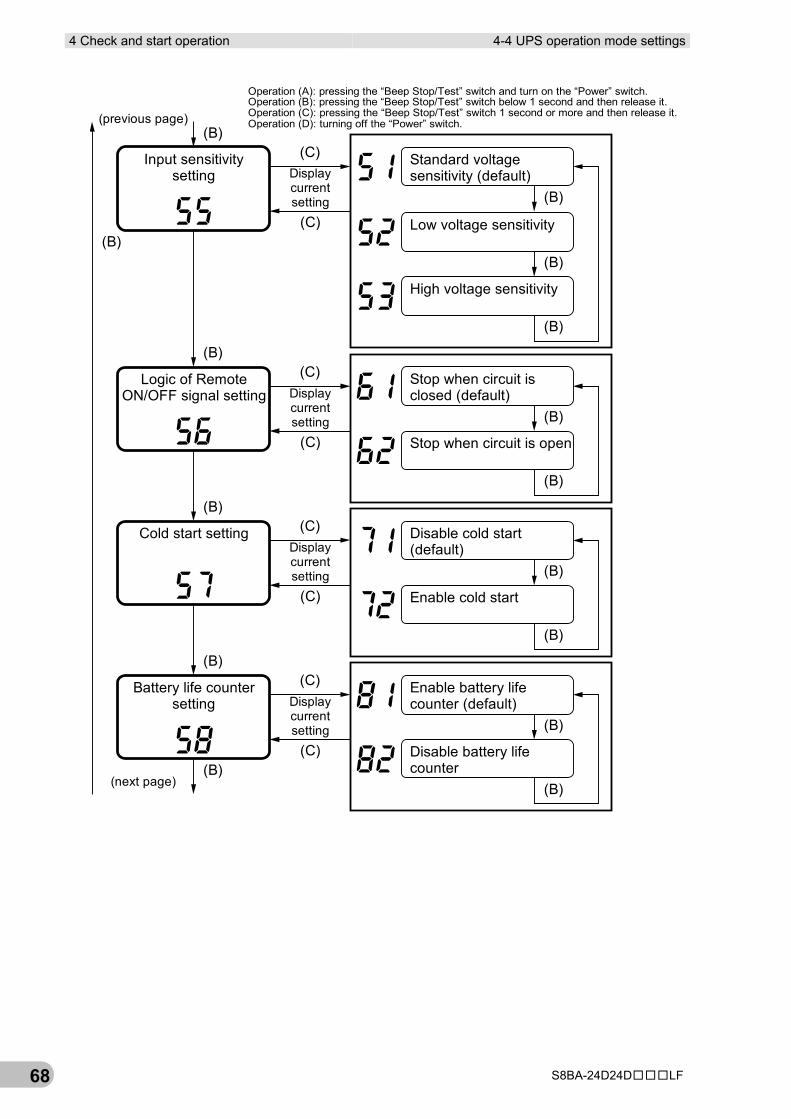
4 Check and start operation 4-4 UPS operation mode settings
S8BA-24D24D□□□LF 68
(C)
(C)(B)
(B)
(B)
(B)
(B)
(B)
(B)
(B)
(B)
(C)
(C)
(C)
(C)
(B)
(B)
(B)
(C)
(C)
(B)
(B)
(B)
Displaycurrentsetting
(next page)
Displaycurrentsetting
Displaycurrentsetting
Displaycurrentsetting
(previous page)
Battery life countersetting
Standard voltagesensitivity (default)
High voltage sensitivity
Stop when circuit isclosed (default)
Stop when circuit is open
Enable cold start
Enable battery lifecounter (default)
Disable battery lifecounter
Disable cold start(default)
Low voltage sensitivity
Logic of RemoteON/OFF signal setting
Input sensitivitysetting
Cold start setting
Operation (A): pressing the “Beep Stop/Test” switch and turn on the “Power” switch.Operation (B): pressing the “Beep Stop/Test” switch below 1 second and then release it.Operation (C): pressing the “Beep Stop/Test” switch 1 second or more and then release it.Operation (D): turning off the “Power” switch.
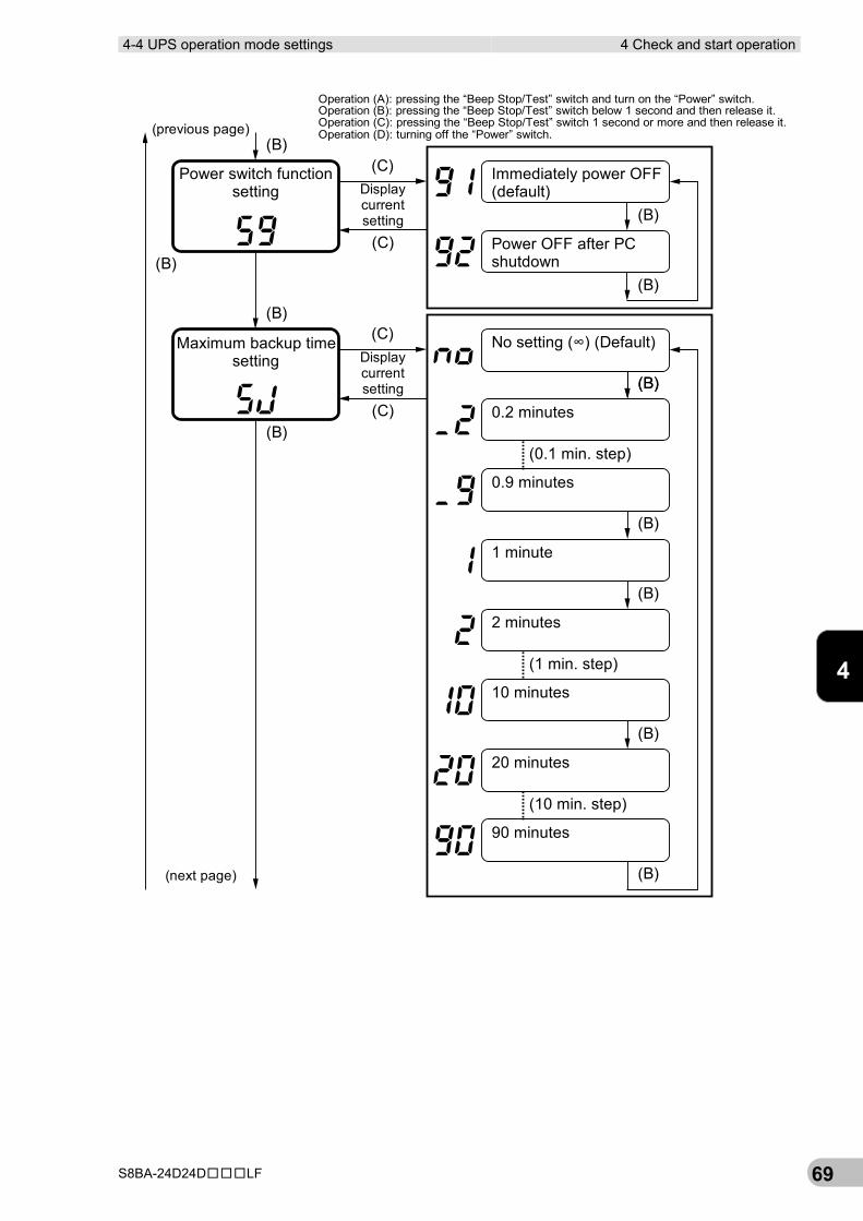
4-4 UPS operation mode settings 4 Check and start operation
S8BA-24D24D□□□LF 69
4
(C)
(C)(B)
(B)
(B)
(B)
(B)
(B)
(B)
(B)
(B)(C)
(C)
(B)
(B)
(B)
Power switch functionsetting Display
currentsetting
Immediately power OFF(default)
Power OFF after PCshutdown
(previous page)
0.2 minutes
1 minute
2 minutes
10 minutes
(1 min. step)
Maximum backup timesetting
(0.1 min. step)
Displaycurrentsetting
0.9 minutes
No setting (∞) (Default)
20 minutes
90 minutes
(10 min. step)
(next page)
Operation (A): pressing the “Beep Stop/Test” switch and turn on the “Power” switch.Operation (B): pressing the “Beep Stop/Test” switch below 1 second and then release it.Operation (C): pressing the “Beep Stop/Test” switch 1 second or more and then release it.Operation (D): turning off the “Power” switch.
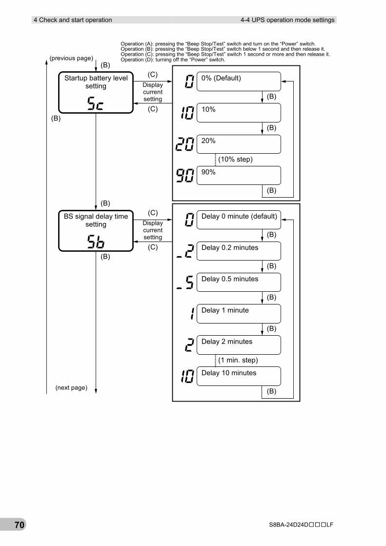
4 Check and start operation 4-4 UPS operation mode settings
S8BA-24D24D□□□LF 70
(C)
(C)
(B)
(B)
(B)
(B)
(B)
(B)
(C)
(C)
(B)
(B)
(B)
(B)
(B)
(B)
BS signal delay timesetting Display
currentsetting
20%
90%
0% (Default)
(10% step)
10%
Delay 0 minute (default)
Delay 0.2 minutes
Delay 0.5 minutes
Delay 1 minute
Delay 2 minutes
Delay 10 minutes
(1 min. step)
Startup battery levelsetting Display
currentsetting
(previous page)
(next page)
Operation (A): pressing the “Beep Stop/Test” switch and turn on the “Power” switch.Operation (B): pressing the “Beep Stop/Test” switch below 1 second and then release it.Operation (C): pressing the “Beep Stop/Test” switch 1 second or more and then release it.Operation (D): turning off the “Power” switch.
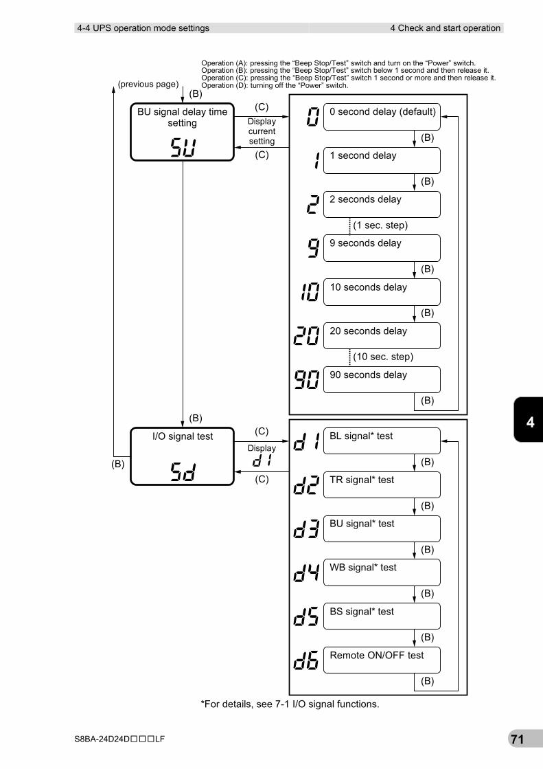
4-4 UPS operation mode settings 4 Check and start operation
S8BA-24D24D□□□LF 71
4
(C)
(C)(B)
(B)
(B)
(B)
(B)
(C)
(C)
(B)
(B)
(B)
(B)
(B)
(B)
(B)
(B)
(B)
1 second delay
2 seconds delay
9 seconds delay
0 second delay (default)BU signal delay timesetting Display
currentsetting
20 seconds delay
10 seconds delay
(1 sec. step)
TR signal* test
BU signal* test
WB signal* test
BL signal* testI/O signal testDisplay
Remote ON/OFF test
BS signal* test
90 seconds delay
(10 sec. step)
(previous page)
*For details, see 7-1 I/O signal functions.
Operation (A): pressing the “Beep Stop/Test” switch and turn on the “Power” switch.Operation (B): pressing the “Beep Stop/Test” switch below 1 second and then release it.Operation (C): pressing the “Beep Stop/Test” switch 1 second or more and then release it.Operation (D): turning off the “Power” switch.
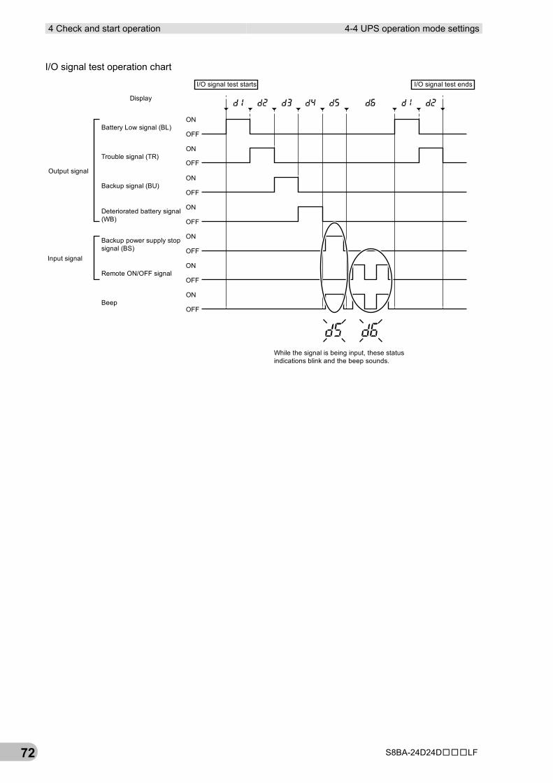
4 Check and start operation 4-4 UPS operation mode settings
S8BA-24D24D□□□LF 72
I/O signal test operation chart
ON
OFF
ON
OFF
ON
OFF
ON
OFF
ON
OFF
ON
OFF
ON
OFF
Battery Low signal (BL)
Trouble signal (TR)
Backup signal (BU)
Deteriorated battery signal(WB)
Backup power supply stopsignal (BS)
Remote ON/OFF signal
Beep
Output signal
Input signal
While the signal is being input, these statusindications blink and the beep sounds.
I/O signal test starts I/O signal test ends
Display
5-1 Checking the battery 5 Maintenance and inspection
S8BA-24D24D□□□LF 73
5
5 Maintenance and inspection For cautions when maintaining the UPS, refer to “Caution (for maintenance)” shown in the “Safety precautions” of the beginning of this manual.
5-1 Checking the battery The battery used in the unit has a limited lifespan. (The life varies depending on your storage/use environment and backup frequency.)
The nearer the end of the life is, the more rapidly deterioration proceeds.
5-1-1 Battery life expectancy Ambient temperature Battery life expectancy
50°C 2.5 years
40°C 5 years
25°C 10 years
*Not a guaranteed performance.
5-1-2 Self-diagnosis test This test performs a failure diagnosis on the unit and performs a test to check for battery deterioration. Use the procedure below to check whether a circuit failure has occurred inside the unit and whether battery replacement is required.
There are two, automatic testing and manual testing, in the self-diagnosis test as follows.
■ Automatic testing The self-diagnosis test is automatically performed at the factory settings, at the following timing in the state that the UPS is connected to a commercial power source and the charge of the battery has been completed. User’s operation to start the test is unnecessary.
▪ When the UPS is started up by pressing the “Power” switch
▪ When power has been supplied for four weeks
If the battery is not sufficiently charged, the self-diagnostic test is not performed. The test is automatically performed when the battery is charged completely.
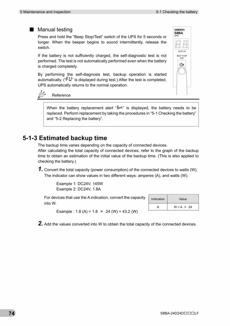
5 Maintenance and inspection 5-1 Checking the battery
S8BA-24D24D□□□LF 74
■ Manual testing Press and hold the “Beep Stop/Test” switch of the UPS for 5 seconds or longer. When the beeper begins to sound intermittently, release the switch.
If the battery is not sufficiently charged, the self-diagnostic test is not performed. The test is not automatically performed even when the battery is charged completely.
By performing the self-diagnosis test, backup operation is started automatically. (“ ” is displayed during test.) After the test is completed, UPS automatically returns to the normal operation.
Reference
When the battery replacement alert “ ” is displayed, the battery needs to be replaced. Perform replacement by taking the procedures in “5-1 Checking the battery” and “5-2 Replacing the battery”.
5-1-3 Estimated backup time The backup time varies depending on the capacity of connected devices. After calculating the total capacity of connected devices, refer to the graph of the backup time to obtain an estimation of the initial value of the backup time. (This is also applied to checking the battery.)
1. Convert the total capacity (power consumption) of the connected devices to watts (W). The indicator can show values in two different ways: amperes (A), and watts (W).
Example 1: DC24V, 145W Example 2: DC24V, 1.8A
For devices that use the A indication, convert the capacity into W.
Example : 1.8 (A) = 1.8 × 24 (W) = 43.2 (W)
2. Add the values converted into W to obtain the total capacity of the connected devices.
Indication Value
A W = A × 24
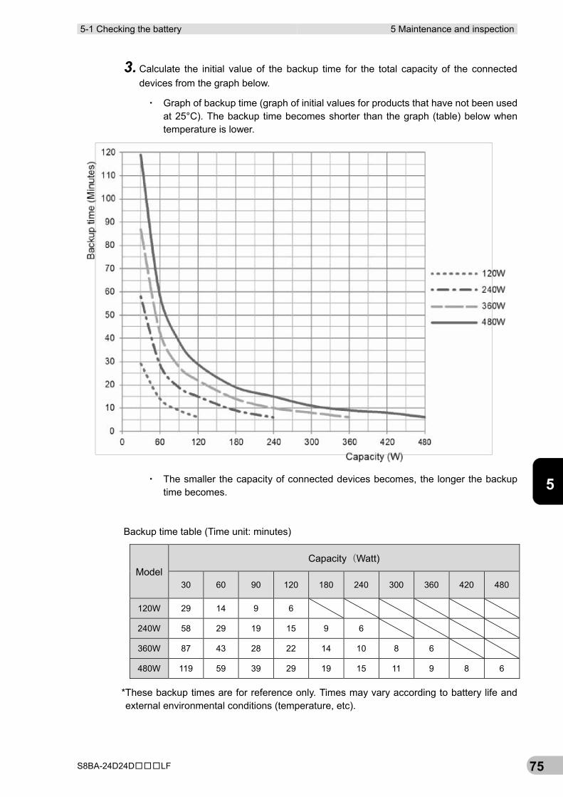
5-1 Checking the battery 5 Maintenance and inspection
S8BA-24D24D□□□LF 75
5
3. Calculate the initial value of the backup time for the total capacity of the connected devices from the graph below.
▪ Graph of backup time (graph of initial values for products that have not been used at 25°C). The backup time becomes shorter than the graph (table) below when temperature is lower.
▪ The smaller the capacity of connected devices becomes, the longer the backup time becomes.
Backup time table (Time unit: minutes)
Model Capacity(Watt)
30 60 90 120 180 240 300 360 420 480
120W 29 14 9 6
240W 58 29 19 15 9 6
360W 87 43 28 22 14 10 8 6
480W 119 59 39 29 19 15 11 9 8 6
*These backup times are for reference only. Times may vary according to battery life and external environmental conditions (temperature, etc).
5 Maintenance and inspection 5-2 Replacing the battery
S8BA-24D24D□□□LF 76
5-2 Replacing the battery This UPS supports hot swapping. Battery replacement is possible both when the power is turned OFF (while the power output is OFF) and when the power is turned ON (while the power output is ON).
Notes
▪For battery replacement, hold down the “Beep Stop/Test” switch on the unit for 10 seconds or longer to activate the battery replacement mode. Resetting is complete when “ ” is displayed. * Perform a reset with the “input power supply” ON.
If you replace the battery without activating the battery replacement mode, the battery life may not be detected accurately because the battery life counter is not reset.
▪Do not replace the battery while the UPS is operating in backup mode. Output will stop.
Reference
▪ If an input power supply error such as a power failure occurs when replacing the battery while in operation, backup cannot be performed and output stops.
▪ When the battery replacement LED lights “ ” up/blinks and beeper sounds, press the “Beep Stop/Test” switch for 0.5 seconds to stop the beeper. (Lighting/blinking of the battery replacement LED lights “ ” does not disappear.)
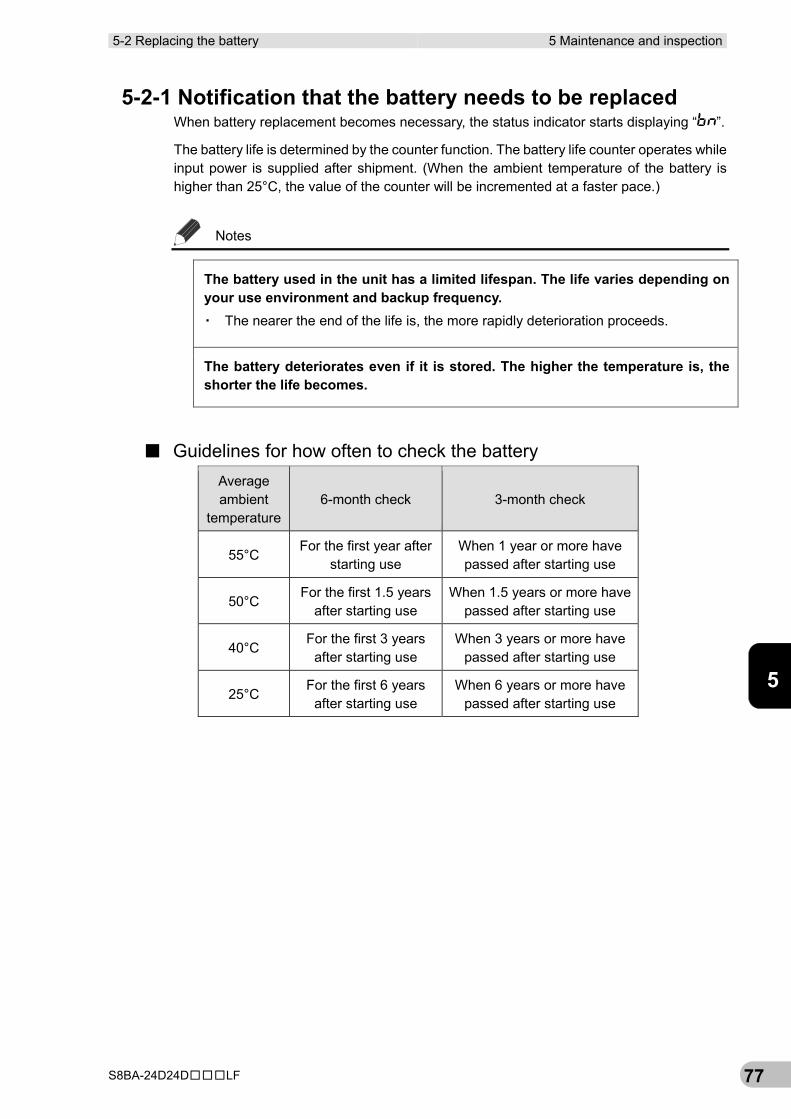
5-2 Replacing the battery 5 Maintenance and inspection
S8BA-24D24D□□□LF 77
5
5-2-1 Notification that the battery needs to be replaced When battery replacement becomes necessary, the status indicator starts displaying “ ”.
The battery life is determined by the counter function. The battery life counter operates while input power is supplied after shipment. (When the ambient temperature of the battery is higher than 25°C, the value of the counter will be incremented at a faster pace.)
Notes
The battery used in the unit has a limited lifespan. The life varies depending on your use environment and backup frequency. ▪ The nearer the end of the life is, the more rapidly deterioration proceeds.
The battery deteriorates even if it is stored. The higher the temperature is, the shorter the life becomes.
■ Guidelines for how often to check the battery Average ambient
temperature 6-month check 3-month check
55°C For the first year after
starting use When 1 year or more have passed after starting use
50°C For the first 1.5 years
after starting use When 1.5 years or more have
passed after starting use
40°C For the first 3 years
after starting use When 3 years or more have
passed after starting use
25°C For the first 6 years
after starting use When 6 years or more have
passed after starting use
5 Maintenance and inspection 5-2 Replacing the battery
S8BA-24D24D□□□LF 78
5-2-2 Procedure for replacing the battery For cautions when replacing the battery of the UPS, refer to “Caution for battery replacement)” shown in the “Safety precautions” of the beginning of this manual.
Notes
Be sure to activate the battery replacement mode before replacing the battery. ▪ For battery replacement, hold down the “Beep Stop/Test” switch on the unit for 10
seconds or longer to activate the battery replacement mode. When the battery replacement mode is activated, the battery life counter is reset. If the battery life counter is not reset, a battery deterioration alarm may occur before the expected life of the battery expires.
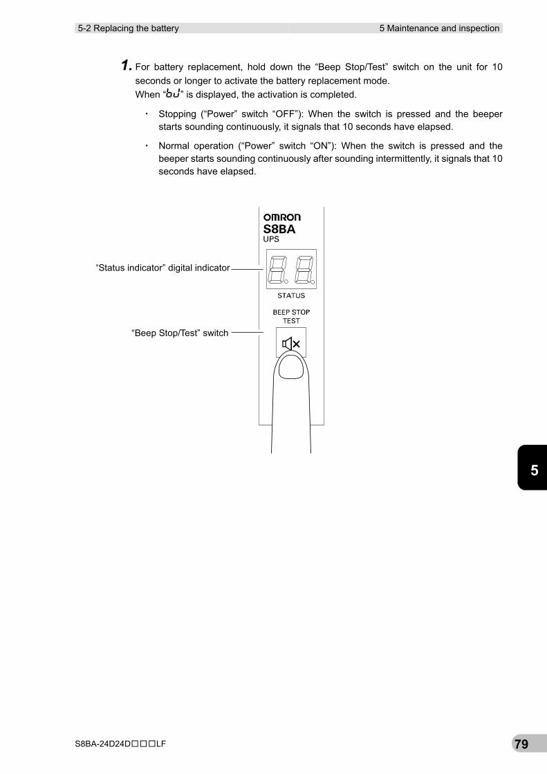
5-2 Replacing the battery 5 Maintenance and inspection
S8BA-24D24D□□□LF 79
5
1. For battery replacement, hold down the “Beep Stop/Test” switch on the unit for 10 seconds or longer to activate the battery replacement mode. When “ ” is displayed, the activation is completed.
▪ Stopping (“Power” switch “OFF”): When the switch is pressed and the beeper starts sounding continuously, it signals that 10 seconds have elapsed.
▪ Normal operation (“Power” switch “ON”): When the switch is pressed and the beeper starts sounding continuously after sounding intermittently, it signals that 10 seconds have elapsed.
“Status indicator” digital indicator
“Beep Stop/Test” switch
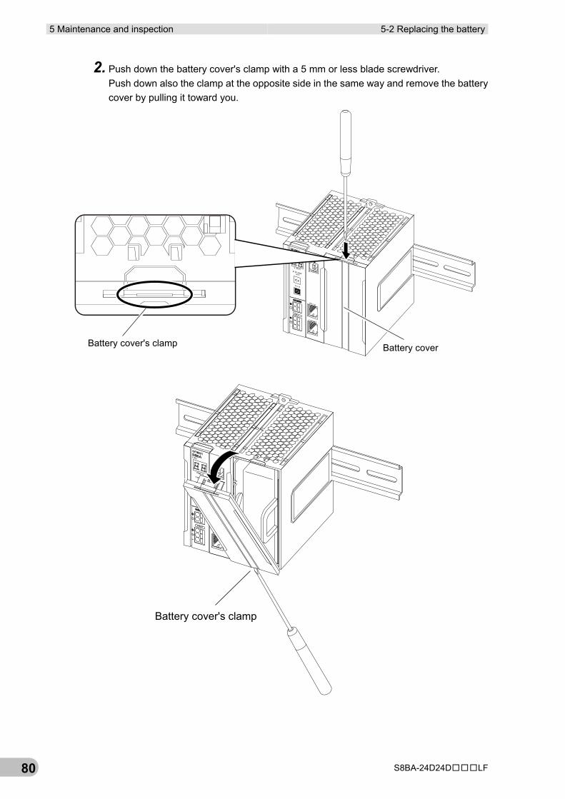
5 Maintenance and inspection 5-2 Replacing the battery
S8BA-24D24D□□□LF 80
2. Push down the battery cover's clamp with a 5 mm or less blade screwdriver. Push down also the clamp at the opposite side in the same way and remove the battery cover by pulling it toward you.
Battery cover's clamp Battery cover
Battery cover's clamp
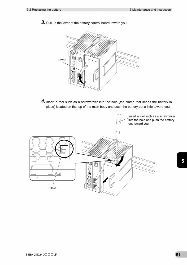
5-2 Replacing the battery 5 Maintenance and inspection
S8BA-24D24D□□□LF 81
5
3. Pull up the lever of the battery control board toward you.
4. Insert a tool such as a screwdriver into the hole (the clamp that keeps the battery in place) located on the top of the main body and push the battery out a little toward you.
Lever
Insert a tool such as a screwdriverinto the hole and push the batteryout toward you
Hole
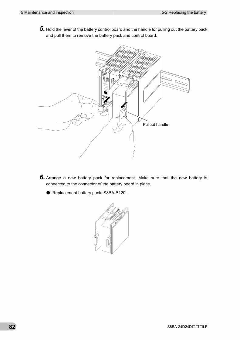
5 Maintenance and inspection 5-2 Replacing the battery
S8BA-24D24D□□□LF 82
5. Hold the lever of the battery control board and the handle for pulling out the battery pack and pull them to remove the battery pack and control board.
6. Arrange a new battery pack for replacement. Make sure that the new battery is connected to the connector of the battery board in place.
● Replacement battery pack: S8BA-B120L
Pullout handle
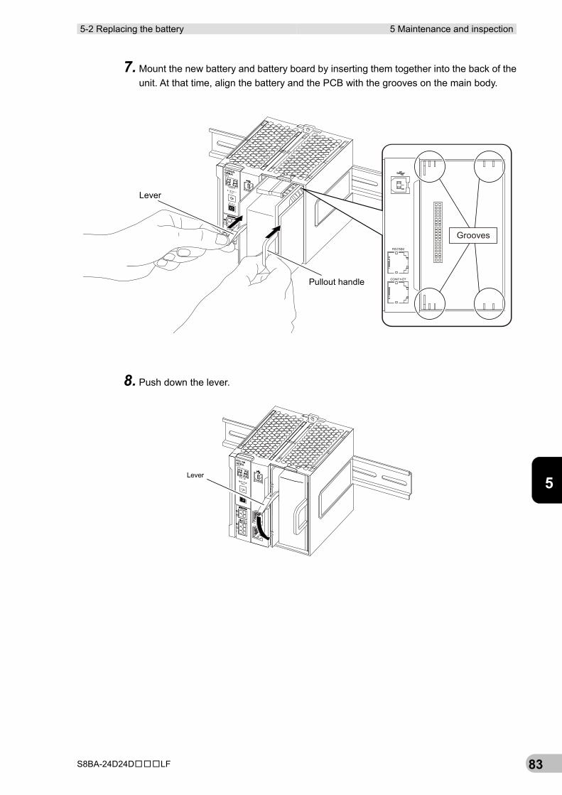
5-2 Replacing the battery 5 Maintenance and inspection
S8BA-24D24D□□□LF 83
5
7. Mount the new battery and battery board by inserting them together into the back of the unit. At that time, align the battery and the PCB with the grooves on the main body.
8. Push down the lever.
Pullout handle
Lever
Grooves
Lever
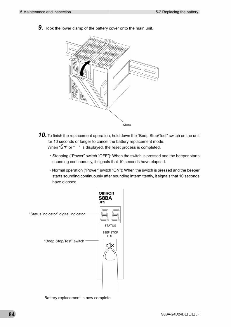
5 Maintenance and inspection 5-2 Replacing the battery
S8BA-24D24D□□□LF 84
9. Hook the lower clamp of the battery cover onto the main unit.
10. To finish the replacement operation, hold down the “Beep Stop/Test” switch on the unit for 10 seconds or longer to cancel the battery replacement mode. When “ ” or “ ” is displayed, the reset process is completed.
・Stopping (“Power” switch “OFF”): When the switch is pressed and the beeper starts sounding continuously, it signals that 10 seconds have elapsed.
・Normal operation (“Power” switch “ON”): When the switch is pressed and the beeper starts sounding continuously after sounding intermittently, it signals that 10 seconds have elapsed.
Battery replacement is now complete.
Clamp
“Status indicator” digital indicator
“Beep Stop/Test” switch
5-3 Cleaning 5 Maintenance and inspection
S8BA-24D24D□□□LF 85
5
5-3 Cleaning
1. Cleaning the UPS
Moisten a soft cloth with water or detergent, squeeze it tightly, and wipe the product lightly. Do not use chemicals such as thinner and benzene. (They cause deformation or discoloration.)
2. Removing dust from the input terminal block and the output terminal block terminal blocks of the UPS
Stop all the connected devices and the UPS and turn the “input power supply” OFF. Then, remove dust with a dry cloth and turn the “input power supply” ON again.
*For information on the connection procedure, see “3-2 Connection”.

5 Maintenance and inspection 5-3 Cleaning
S8BA-24D24D□□□LF 86
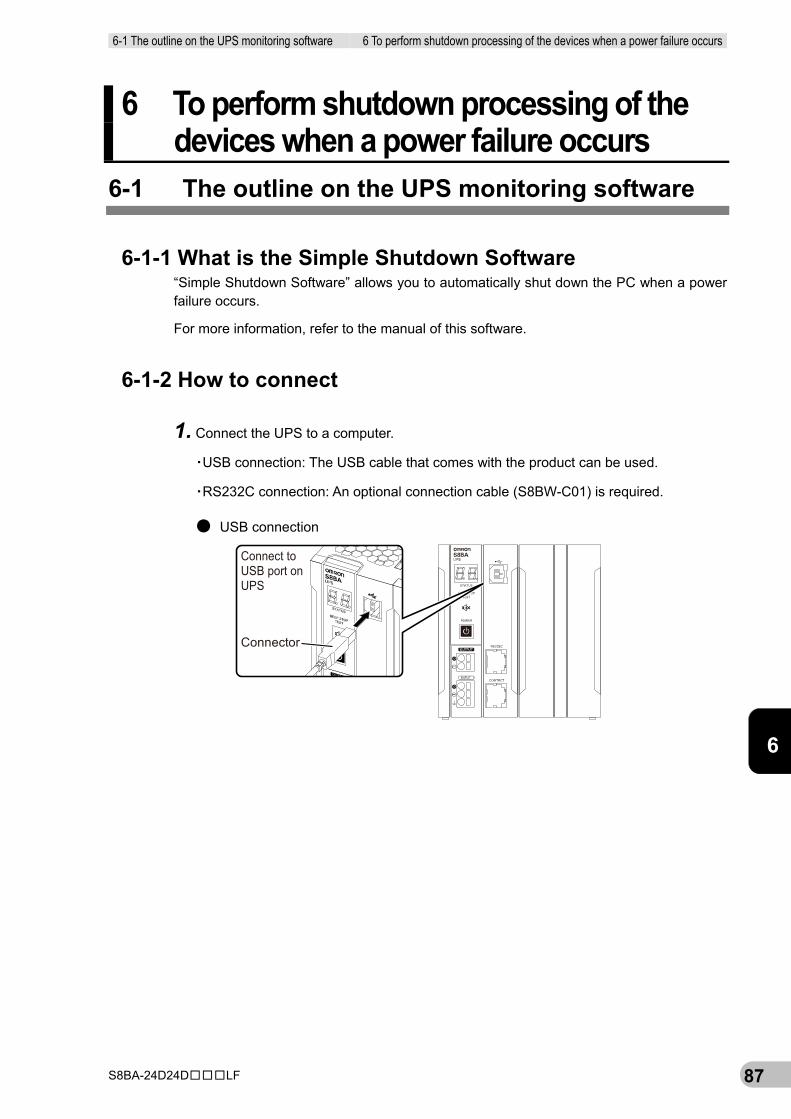
6-1 The outline on the UPS monitoring software 6 To perform shutdown processing of the devices when a power failure occurs
S8BA-24D24D□□□LF 87
6
6 To perform shutdown processing of the devices when a power failure occurs
6-1 The outline on the UPS monitoring software
6-1-1 What is the Simple Shutdown Software “Simple Shutdown Software” allows you to automatically shut down the PC when a power failure occurs.
For more information, refer to the manual of this software.
6-1-2 How to connect
1. Connect the UPS to a computer.
▪USB connection: The USB cable that comes with the product can be used.
▪RS232C connection: An optional connection cable (S8BW-C01) is required.
● USB connection
Connect toUSB port onUPS
Connector
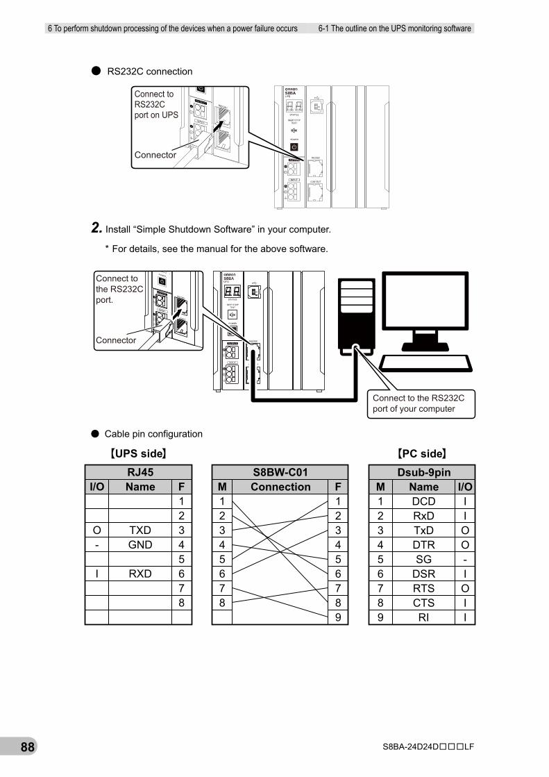
6 To perform shutdown processing of the devices when a power failure occurs 6-1 The outline on the UPS monitoring software
S8BA-24D24D□□□LF 88
● RS232C connection
2. Install “Simple Shutdown Software” in your computer.
* For details, see the manual for the above software.
● Cable pin configuration
Connect toRS232Cport on UPS
Connector
Connect tothe RS232Cport.
Connector
Connect to the RS232Cport of your computer
【UPS side】 【PC side】
I/O
O-
I
RJ45Name
TXDGND
RXD
F12345678
M12345678
S8BW-C01Connection F
123456789
M123456789
Dsub-9pinNameDCDRxDTxDDTRSG
DSRRTSCTSRI
I/OIIOO-IOII
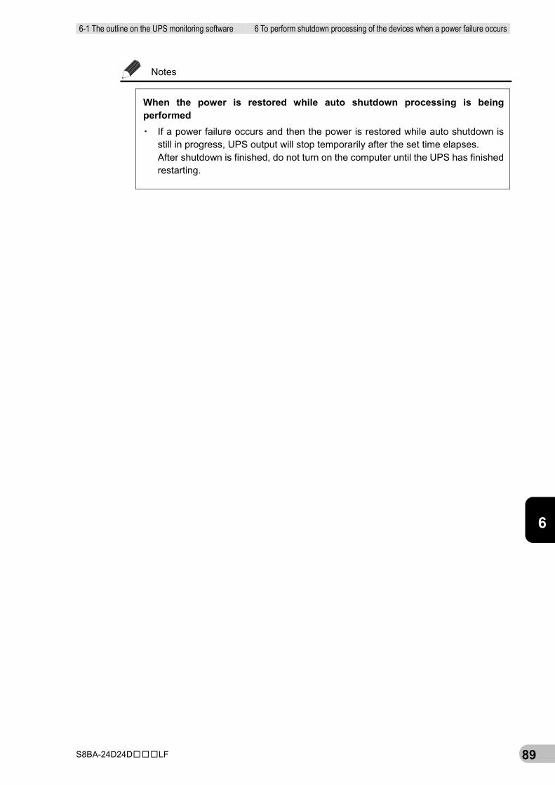
6-1 The outline on the UPS monitoring software 6 To perform shutdown processing of the devices when a power failure occurs
S8BA-24D24D□□□LF 89
6
Notes
When the power is restored while auto shutdown processing is being performed ▪ If a power failure occurs and then the power is restored while auto shutdown is
still in progress, UPS output will stop temporarily after the set time elapses. After shutdown is finished, do not turn on the computer until the UPS has finished restarting.

6 To perform shutdown processing of the devices when a power failure occurs 6-1 The outline on the UPS monitoring software
S8BA-24D24D□□□LF 90
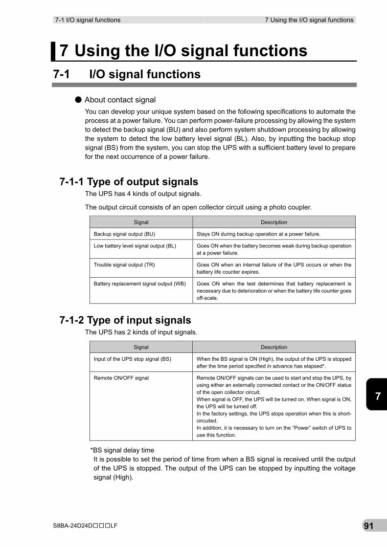
7-1 I/O signal functions 7 Using the I/O signal functions
S8BA-24D24D□□□LF 91
7
7 Using the I/O signal functions 7-1 I/O signal functions
● About contact signal You can develop your unique system based on the following specifications to automate the process at a power failure. You can perform power-failure processing by allowing the system to detect the backup signal (BU) and also perform system shutdown processing by allowing the system to detect the low battery level signal (BL). Also, by inputting the backup stop signal (BS) from the system, you can stop the UPS with a sufficient battery level to prepare for the next occurrence of a power failure.
7-1-1 Type of output signals The UPS has 4 kinds of output signals.
The output circuit consists of an open collector circuit using a photo coupler.
Signal Description
Backup signal output (BU) Stays ON during backup operation at a power failure.
Low battery level signal output (BL) Goes ON when the battery becomes weak during backup operation at a power failure.
Trouble signal output (TR) Goes ON when an internal failure of the UPS occurs or when the battery life counter expires.
Battery replacement signal output (WB) Goes ON when the test determines that battery replacement is necessary due to deterioration or when the battery life counter goes off-scale.
7-1-2 Type of input signals The UPS has 2 kinds of input signals.
Signal Description
Input of the UPS stop signal (BS) When the BS signal is ON (High), the output of the UPS is stopped after the time period specified in advance has elapsed*.
Remote ON/OFF signal Remote ON/OFF signals can be used to start and stop the UPS, by using either an externally connected contact or the ON/OFF status of the open collector circuit. When signal is OFF, the UPS will be turned on. When signal is ON, the UPS will be turned off. In the factory settings, the UPS stops operation when this is short-circuited. In addition, it is necessary to turn on the “Power” switch of UPS to use this function.
*BS signal delay time It is possible to set the period of time from when a BS signal is received until the output of the UPS is stopped. The output of the UPS can be stopped by inputting the voltage signal (High).
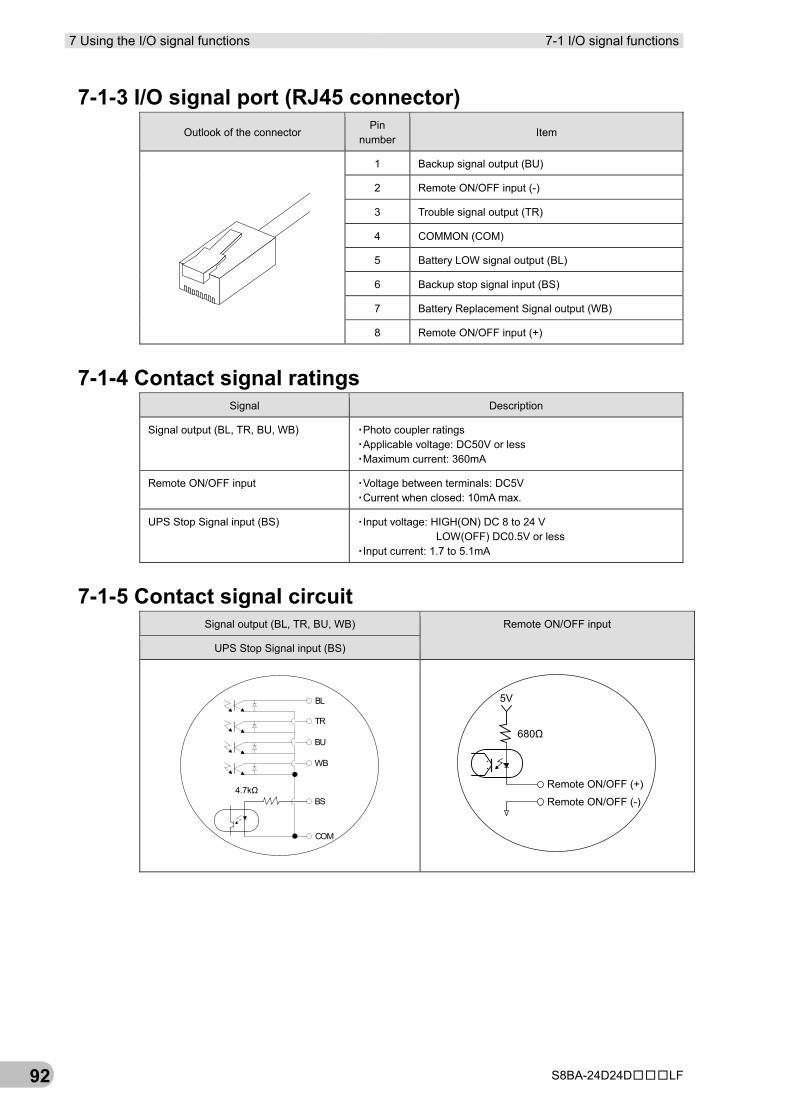
7 Using the I/O signal functions 7-1 I/O signal functions
S8BA-24D24D□□□LF 92
7-1-3 I/O signal port (RJ45 connector) Outlook of the connector
Pin number
Item
1 Backup signal output (BU)
2 Remote ON/OFF input (-)
3 Trouble signal output (TR)
4 COMMON (COM)
5 Battery LOW signal output (BL)
6 Backup stop signal input (BS)
7 Battery Replacement Signal output (WB)
8 Remote ON/OFF input (+)
7-1-4 Contact signal ratings Signal Description
Signal output (BL, TR, BU, WB) ▪Photo coupler ratings ▪Applicable voltage: DC50V or less ▪Maximum current: 360mA
Remote ON/OFF input ▪Voltage between terminals: DC5V ▪Current when closed: 10mA max.
UPS Stop Signal input (BS) ▪Input voltage: HIGH(ON) DC 8 to 24 V LOW(OFF) DC0.5V or less
▪Input current: 1.7 to 5.1mA
7-1-5 Contact signal circuit Signal output (BL, TR, BU, WB) Remote ON/OFF input
UPS Stop Signal input (BS)
BL
TR
BU
WB
BS
COM
4.7kΩ
5V
680Ω
Remote ON/OFF (+)
Remote ON/OFF (-)
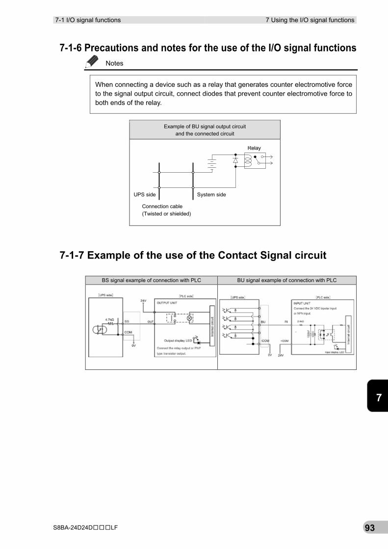
7-1 I/O signal functions 7 Using the I/O signal functions
S8BA-24D24D□□□LF 93
7
7-1-6 Precautions and notes for the use of the I/O signal functions Notes
When connecting a device such as a relay that generates counter electromotive force to the signal output circuit, connect diodes that prevent counter electromotive force to both ends of the relay.
7-1-7 Example of the use of the Contact Signal circuit
BS signal example of connection with PLC BU signal example of connection with PLC
Example of BU signal output circuit and the connected circuit
Relay
Connection cable(Twisted or shielded)
System sideUPS side

7 Using the I/O signal functions 7-1 I/O signal functions
S8BA-24D24D□□□LF 94
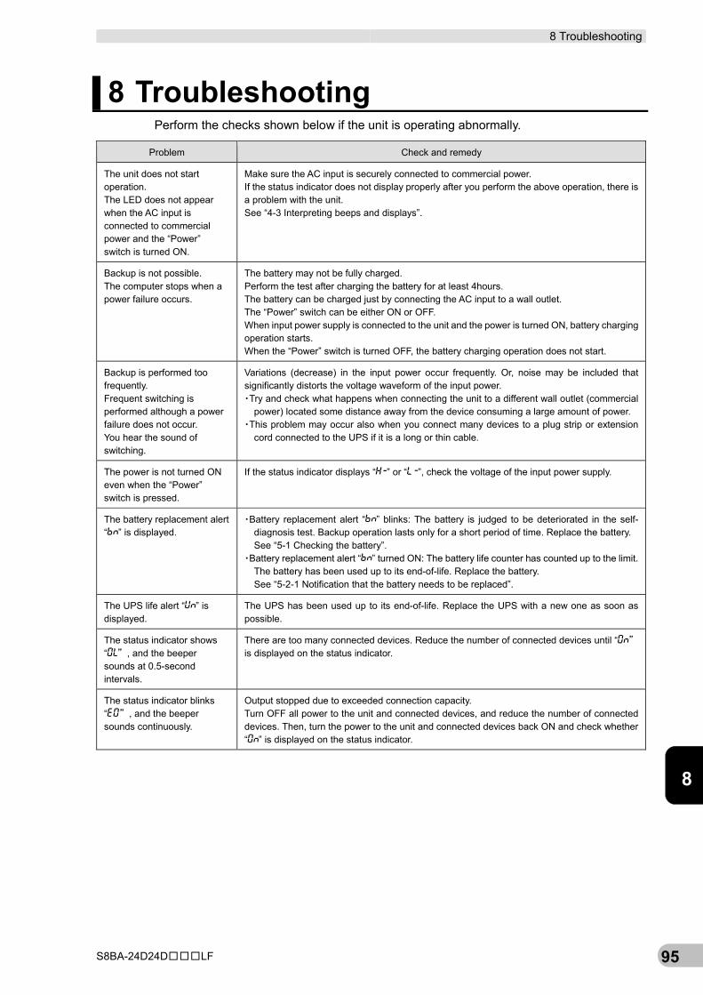
8 Troubleshooting
S8BA-24D24D□□□LF 95
8
8 Troubleshooting Perform the checks shown below if the unit is operating abnormally.
Problem Check and remedy
The unit does not start operation. The LED does not appear when the AC input is connected to commercial power and the “Power” switch is turned ON.
Make sure the AC input is securely connected to commercial power. If the status indicator does not display properly after you perform the above operation, there is a problem with the unit. See “4-3 Interpreting beeps and displays”.
Backup is not possible. The computer stops when a power failure occurs.
The battery may not be fully charged. Perform the test after charging the battery for at least 4hours. The battery can be charged just by connecting the AC input to a wall outlet. The “Power” switch can be either ON or OFF. When input power supply is connected to the unit and the power is turned ON, battery charging operation starts. When the “Power” switch is turned OFF, the battery charging operation does not start.
Backup is performed too frequently. Frequent switching is performed although a power failure does not occur. You hear the sound of switching.
Variations (decrease) in the input power occur frequently. Or, noise may be included that significantly distorts the voltage waveform of the input power. ▪Try and check what happens when connecting the unit to a different wall outlet (commercial
power) located some distance away from the device consuming a large amount of power. ▪This problem may occur also when you connect many devices to a plug strip or extension
cord connected to the UPS if it is a long or thin cable.
The power is not turned ON even when the “Power” switch is pressed.
If the status indicator displays “ ” or “ ”, check the voltage of the input power supply.
The battery replacement alert “ ” is displayed.
▪Battery replacement alert “ ” blinks: The battery is judged to be deteriorated in the self-diagnosis test. Backup operation lasts only for a short period of time. Replace the battery. See “5-1 Checking the battery”.
▪Battery replacement alert “ ” turned ON: The battery life counter has counted up to the limit. The battery has been used up to its end-of-life. Replace the battery. See “5-2-1 Notification that the battery needs to be replaced”.
The UPS life alert “ ” is displayed.
The UPS has been used up to its end-of-life. Replace the UPS with a new one as soon as possible.
The status indicator shows “ ”, and the beeper sounds at 0.5-second intervals.
There are too many connected devices. Reduce the number of connected devices until “ ” is displayed on the status indicator.
The status indicator blinks “ ”, and the beeper sounds continuously.
Output stopped due to exceeded connection capacity. Turn OFF all power to the unit and connected devices, and reduce the number of connected devices. Then, turn the power to the unit and connected devices back ON and check whether “ ” is displayed on the status indicator.

8 Troubleshooting
S8BA-24D24D□□□LF 96
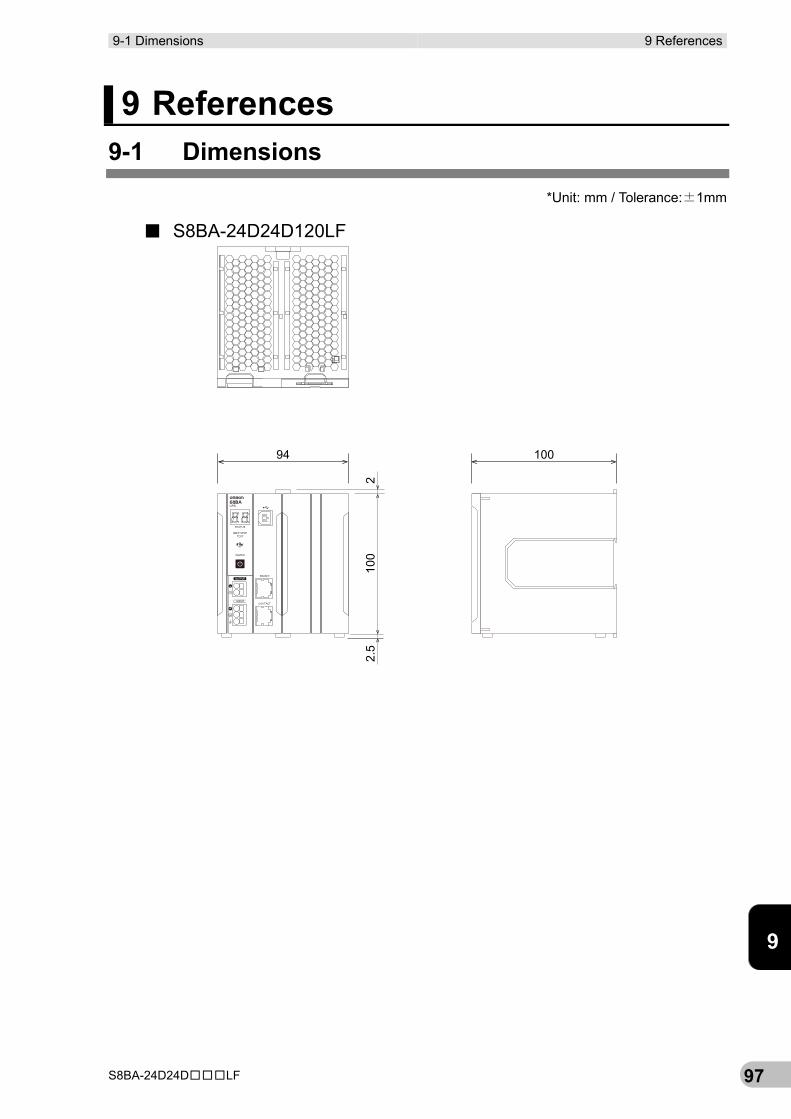
9-1 Dimensions 9 References
S8BA-24D24D□□□LF 97
9
9 References 9-1 Dimensions
*Unit: mm / Tolerance:±1mm
■ S8BA-24D24D120LF
10094
210
02.
5
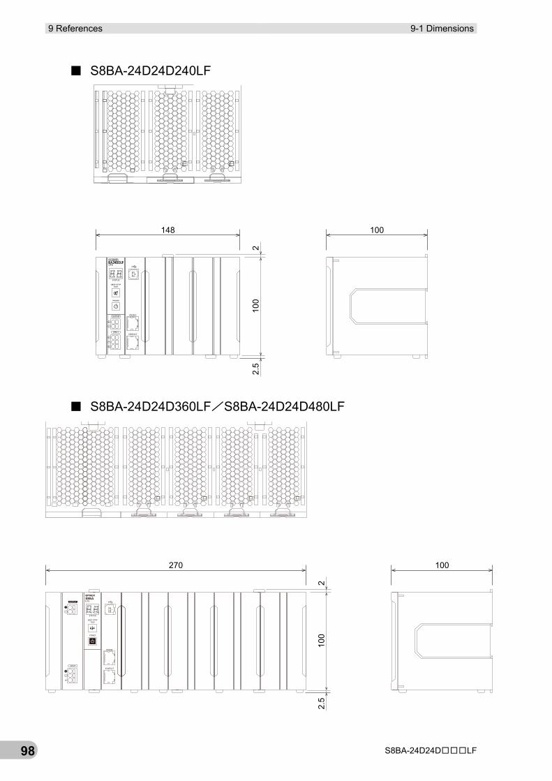
9 References 9-1 Dimensions
S8BA-24D24D□□□LF 98
■ S8BA-24D24D240LF
■ S8BA-24D24D360LF/S8BA-24D24D480LF
100148
210
02.
5
100270
210
02.
5
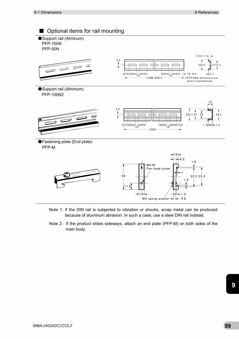
9-1 Dimensions 9 References
S8BA-24D24D□□□LF 99
9
■ Optional items for rail mounting ●Support rail (Alminum)
PFP-100N PFP-50N
●Support rail (Alminum) PFP-100N2
●Fastening plate (End plate) PFP-M
Note 1: If the DIN rail is subjected to vibration or shocks, scrap metal can be produced because of aluminum abrasion. In such a case, use a steel DIN rail instead.
Note 2:If the product slides sideways, attach an end plate (PFP-M) on both sides of the main body.
4 .5
15 25 2510 10
1 ,000( 500)*
25 25 15( 5)*
35±0.3
7 .3±0.15
27±0.15
1
* PFP-50N dimensions areg iven in parentheses.
4 .5
15 25 2510 10
1 ,000
25 25 15 1 1 .5
29 .2242735±0.3
16
50
11 .5
10
M4×8Pan head screw
M4 spring washer 4 .8
1 .3
1 .8
1
10
6 .21 .8
35 .5 35 .3
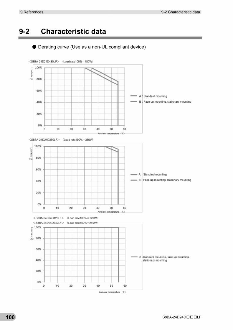
9 References 9-2 Characteristic data
S8BA-24D24D□□□LF 100
9-2 Characteristic data
● Derating curve (Use as a non-UL compliant device)
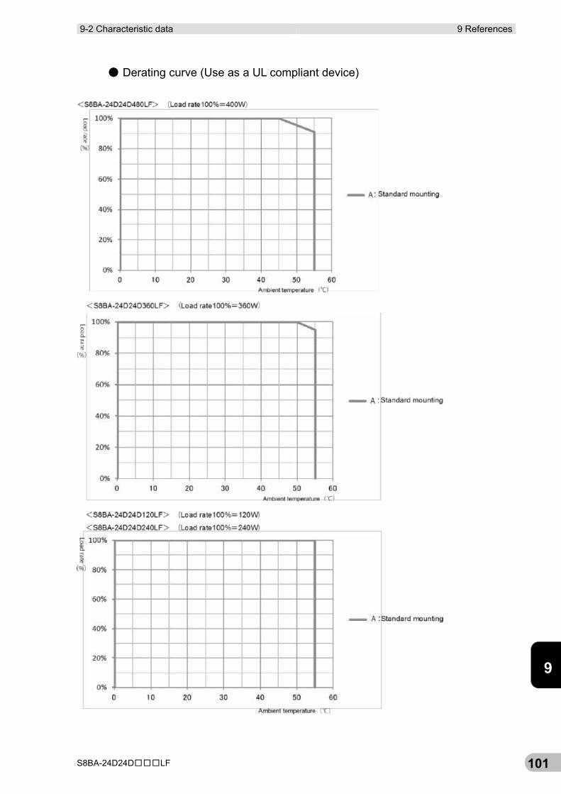
9-2 Characteristic data 9 References
S8BA-24D24D□□□LF 101
9
● Derating curve (Use as a UL compliant device)
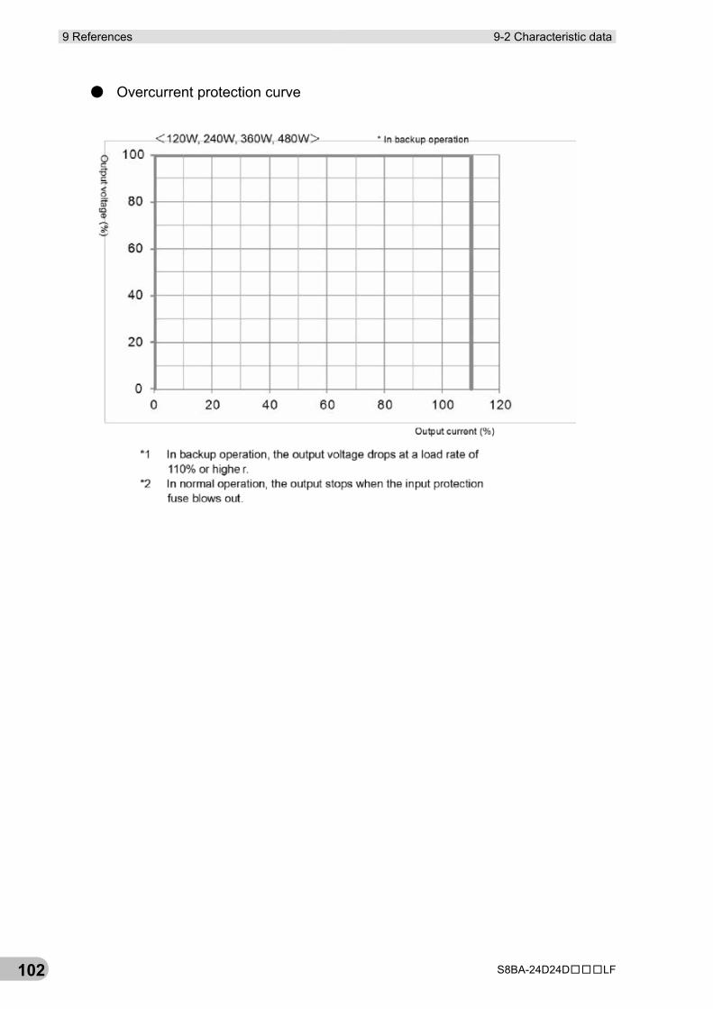
9 References 9-2 Characteristic data
S8BA-24D24D□□□LF 102
● Overcurrent protection curve


Cat. No. U01E-EN-01
Authorized Distributor:
Printed in Europe


