PB-27015 UNION PACIFIC RAILROAD SYSTEM SPECIAL INSTRUCTIONS Effective 0900 CDT Thursday, June 01, 2017 C. A. Scott, Executive Vice President & Chief Operating Officer S. K. Keller, Vice President – Transportation T. A. Lischer, Vice President – HDC & Network Operations G. N. Garrison, Vice President – Northern Region C. A. Wilbourn, Vice President – Southern Region R. M. Castagna, Vice President – Western Region G. D. Workman, Vice President – Engineering J. C. Estes, Chief Mechanical Officer T. F. Jacobi, Vice President – Operating Systems & Practices R. N. Doerr, Vice President – Safety & CSO This document supersedes: Union Pacific Railroad System Special Instructions Effective May 02, 2016
Transcript
PB-27015
UNION PACIFIC RAILROAD
SYSTEM SPECIAL INSTRUCTIONS
Effective 0900 CDT Thursday, June 01, 2017
C. A. Scott, Executive Vice President & Chief Operating Officer S. K. Keller, Vice President – Transportation
T. A. Lischer, Vice President – HDC & Network Operations G. N. Garrison, Vice President – Northern Region C. A. Wilbourn, Vice President – Southern Region R. M. Castagna, Vice President – Western Region
G. D. Workman, Vice President – Engineering J. C. Estes, Chief Mechanical Officer
T. F. Jacobi, Vice President – Operating Systems & Practices R. N. Doerr, Vice President – Safety & CSO
This document supersedes:
Union Pacific Railroad System Special Instructions
Effective May 02, 2016
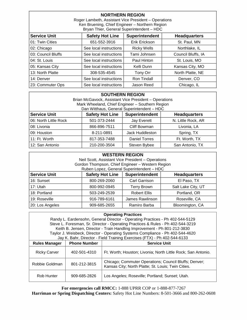
NORTHERN REGION Roger Lambeth, Assistant Vice President – Operations
Ken Bruening, Chief Engineer – Northern Region Bryan Thier, General Superintendent – HDC
Service Unit Safety Hot Line Superintendent Headquarters 01: Twin Cities 651-552-3916 Erik Erickson St. Paul, MN 02: Chicago See local instructions Ricky Wells Northlake, IL 03: Council Bluffs See local instructions Tami Johnsen Council Bluffs, IA 04: St. Louis See local instructions Paul Hinton St. Louis, MO 05: Kansas City See local instructions Kelli Dunn Kansas City, MO 13: North Platte 308-535-4545 Tony Orr North Platte, NE 14: Denver See local instructions Ron Tindall Denver, CO 23: Commuter Ops See local instructions Jason Reed Chicago, IL
SOUTHERN REGION
Brian McGavock, Assistant Vice President – Operations Mark Wheeland, Chief Engineer – Southern Region
Dan Witthaus, General Superintendent – HDC Service Unit Safety Hot Line Superintendent Headquarters 06: North Little Rock 501-373-2444 Jay Everett N. Little Rock, AR 08: Livonia 866-896-7511 Cliff Bowman Livonia, LA 09: Houston 8-211-0891 Jack Huddleston Spring, TX 11: Ft. Worth 817-353-7488 Daniel Torres Ft. Worth, TX 12: San Antonio 210-200-3504 Steven Bybee San Antonio, TX
WESTERN REGION
Neil Scott, Assistant Vice President – Operations Gordon Thompson, Chief Engineer – Western Region
Ruben Lopez, General Superintendent – HDC Service Unit Safety Hot Line Superintendent Headquarters 16: Sunset 800-269-2060 Carl Garrison El Paso, TX 17: Utah 800-992-0945 Terry Brown Salt Lake City, UT 18: Portland 503-249-2539 Robert Ellis Portland, OR 19: Roseville 916-789-6161 James Rawlinson Roseville, CA 20: Los Angeles 909-685-2655 Ramiro Barba Bloomington, CA
Operating Practices
Randy L. Eardensohn, General Director - Operating Practices - Ph 402-544-5129 Steve L. Foresman, Sr. Director - Operating Practices & Rules - Ph 402-544-3219
Keith B. Jensen, Director - Train Handling Improvement - Ph 801-212-3830 Taylor J. Weisbeck, Director - Operating Systems Compliance - Ph 402-544-4620
Jay K. Bahr, Director - Field Training Exercises (FTX) - Ph 402-544-6133 Rules Manager Phone Number Service Unit
Ricky Carver 402-501-4310 Ft. Worth; Houston; Livonia; North Little Rock; San Antonio.
Robbie Goldman 801-212-3815 Chicago; Commuter Operations; Council Bluffs; Denver; Kansas City; North Platte; St. Louis; Twin Cities.
Rob Hunter 909-685-2826 Los Angeles; Roseville; Portland; Sunset; Utah.
For emergencies call RMCC: 1-888 UPRR COP or 1-888-877-7267
Harriman or Spring Dispatching Centers: Safety Hot Line Numbers: 8-501-3666 and 800-262-0608
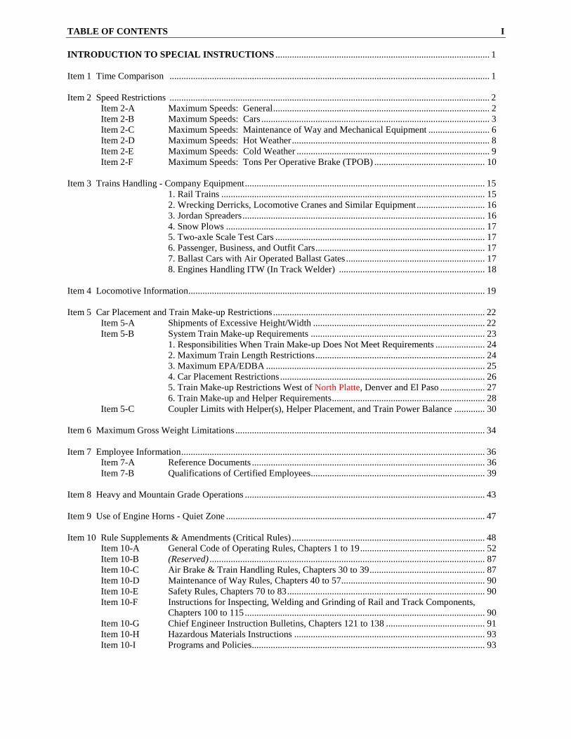
TABLE OF CONTENTS I INTRODUCTION TO SPECIAL INSTRUCTIONS ........................................................................................... 1 Item 1 Time Comparison ........................................................................................................................................ 1 Item 2 Speed Restrictions ........................................................................................................................................ 2
Item 2-A Maximum Speeds: General ............................................................................................ 2 Item 2-B Maximum Speeds: Cars ................................................................................................. 3 Item 2-C Maximum Speeds: Maintenance of Way and Mechanical Equipment .......................... 6 Item 2-D Maximum Speeds: Hot Weather .................................................................................... 8 Item 2-E Maximum Speeds: Cold Weather .................................................................................. 9 Item 2-F Maximum Speeds: Tons Per Operative Brake (TPOB) ............................................... 10
Item 3 Trains Handling - Company Equipment ...................................................................................................... 15
1. Rail Trains ................................................................................................................ 15 2. Wrecking Derricks, Locomotive Cranes and Similar Equipment ............................. 16 3. Jordan Spreaders ....................................................................................................... 16 4. Snow Plows .............................................................................................................. 17 5. Two-axle Scale Test Cars ......................................................................................... 17 6. Passenger, Business, and Outfit Cars ........................................................................ 17 7. Ballast Cars with Air Operated Ballast Gates ........................................................... 17 8. Engines Handling ITW (In Track Welder) .............................................................. 18
Item 4 Locomotive Information .............................................................................................................................. 19 Item 5 Car Placement and Train Make-up Restrictions .......................................................................................... 22 Item 5-A Shipments of Excessive Height/Width ......................................................................... 22 Item 5-B System Train Make-up Requirements .......................................................................... 23
1. Responsibilities When Train Make-up Does Not Meet Requirements ..................... 24 2. Maximum Train Length Restrictions ........................................................................ 24 3. Maximum EPA/EDBA ............................................................................................. 25 4. Car Placement Restrictions ....................................................................................... 26 5. Train Make-up Restrictions West of North Platte, Denver and El Paso ................... 27 6. Train Make-up and Helper Requirements ................................................................. 28
Item 5-C Coupler Limits with Helper(s), Helper Placement, and Train Power Balance ............. 30 Item 6 Maximum Gross Weight Limitations .......................................................................................................... 34 Item 7 Employee Information ................................................................................................................................. 36
Item 8 Heavy and Mountain Grade Operations ...................................................................................................... 43 Item 9 Use of Engine Horns - Quiet Zone .............................................................................................................. 47 Item 10 Rule Supplements & Amendments (Critical Rules) .................................................................................. 48
Item 10-A General Code of Operating Rules, Chapters 1 to 19 ..................................................... 52 Item 10-B (Reserved) ..................................................................................................................... 87 Item 10-C Air Brake & Train Handling Rules, Chapters 30 to 39 ................................................. 87 Item 10-D Maintenance of Way Rules, Chapters 40 to 57 ............................................................. 90 Item 10-E Safety Rules, Chapters 70 to 83 .................................................................................... 90 Item 10-F Instructions for Inspecting, Welding and Grinding of Rail and Track Components, Chapters 100 to 115 ...................................................................................................... 90 Item 10-G Chief Engineer Instruction Bulletins, Chapters 121 to 138 .......................................... 91 Item 10-H Hazardous Materials Instructions ................................................................................. 93 Item 10-I Programs and Policies ................................................................................................... 93
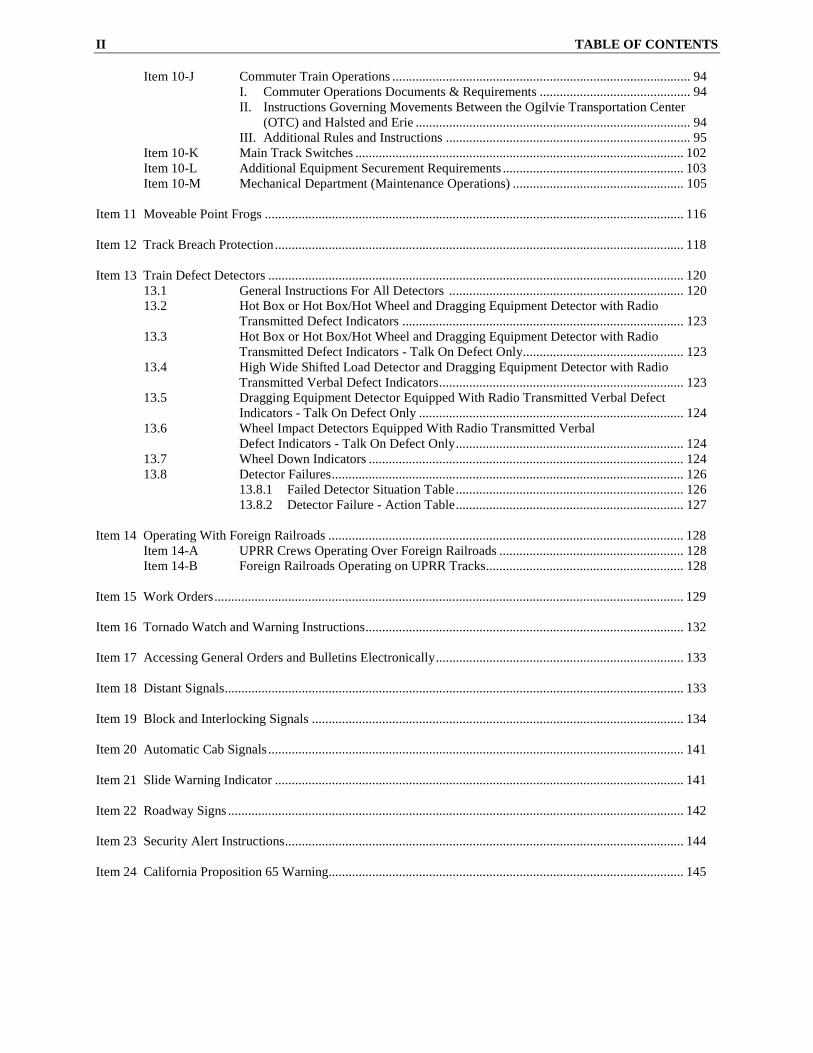
II TABLE OF CONTENTS
Item 10-J Commuter Train Operations ......................................................................................... 94 I. Commuter Operations Documents & Requirements ............................................. 94 II. Instructions Governing Movements Between the Ogilvie Transportation Center (OTC) and Halsted and Erie .................................................................................. 94 III. Additional Rules and Instructions ......................................................................... 95
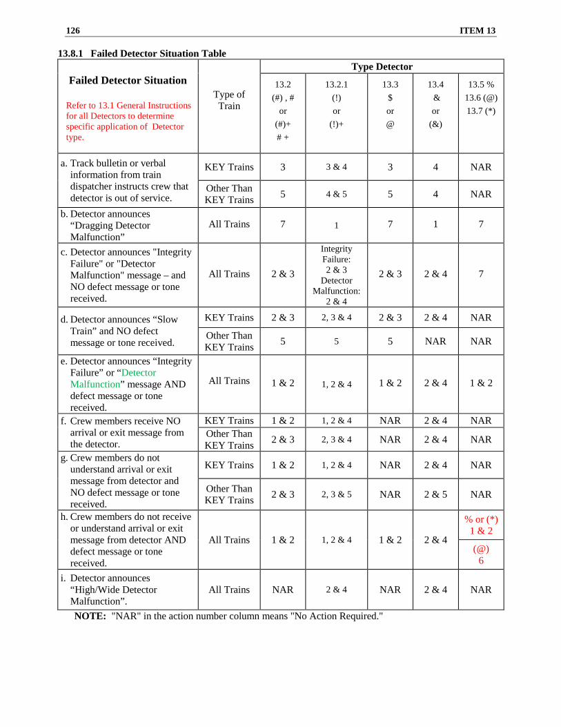
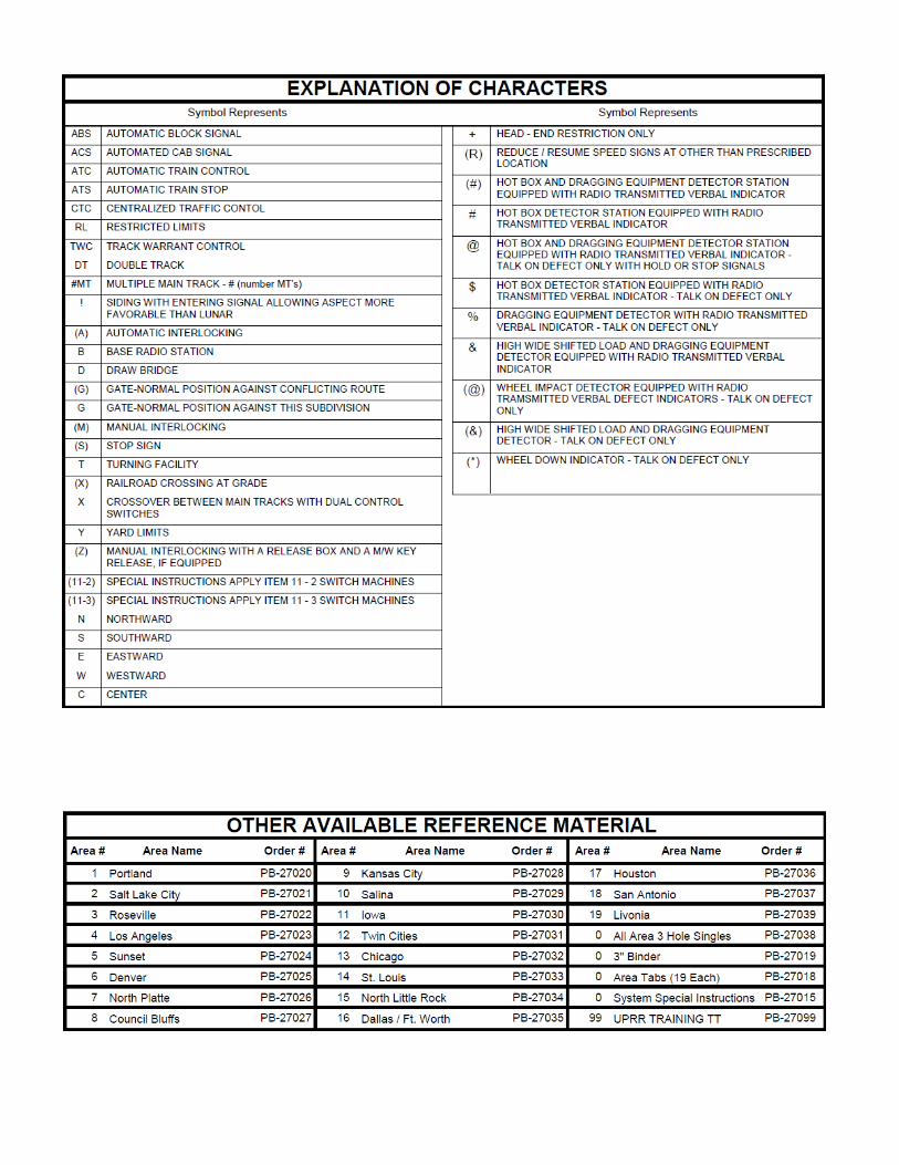
13.1 General Instructions For All Detectors ...................................................................... 120 13.2 Hot Box or Hot Box/Hot Wheel and Dragging Equipment Detector with Radio Transmitted Defect Indicators .................................................................................... 123 13.3 Hot Box or Hot Box/Hot Wheel and Dragging Equipment Detector with Radio Transmitted Defect Indicators - Talk On Defect Only ................................................ 123 13.4 High Wide Shifted Load Detector and Dragging Equipment Detector with Radio
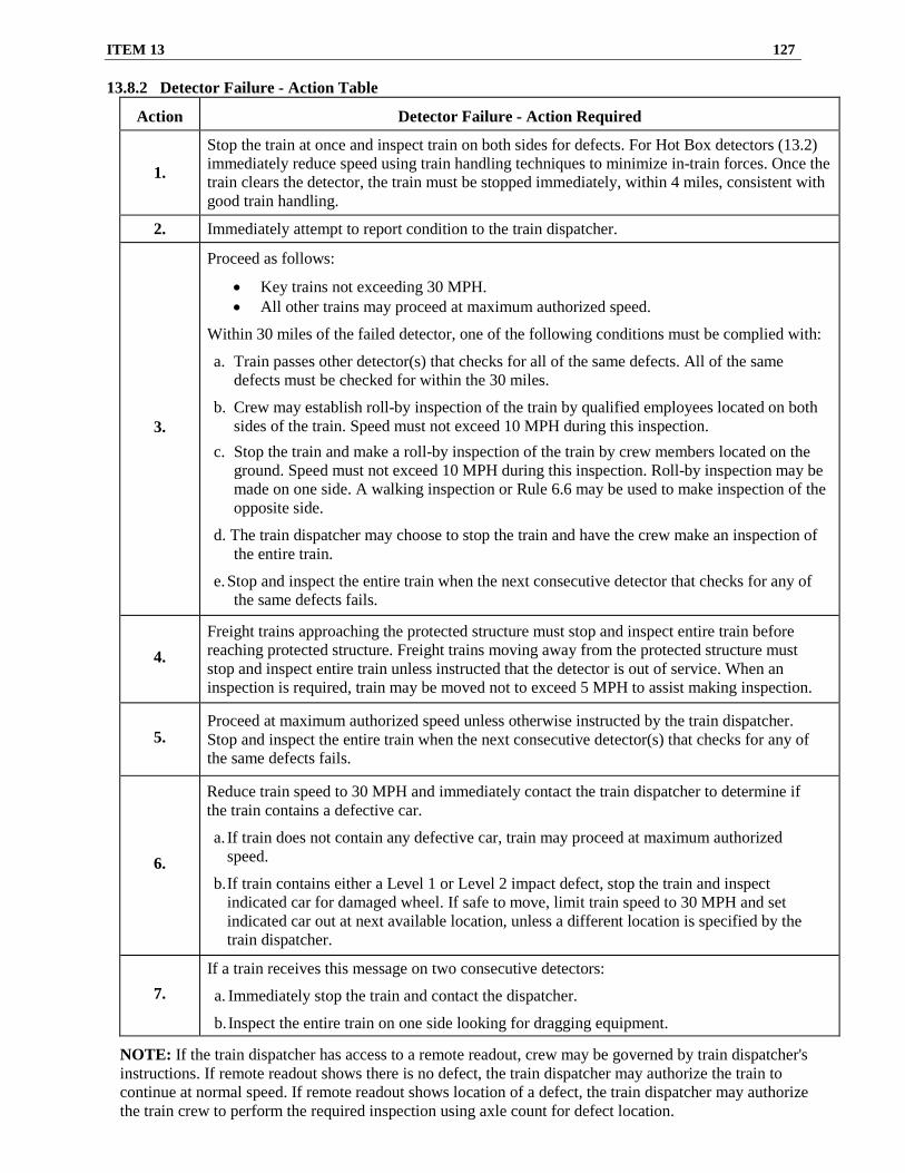
Transmitted Verbal Defect Indicators ......................................................................... 123 13.5 Dragging Equipment Detector Equipped With Radio Transmitted Verbal Defect Indicators - Talk On Defect Only ............................................................................... 124 13.6 Wheel Impact Detectors Equipped With Radio Transmitted Verbal Defect Indicators - Talk On Defect Only .................................................................... 124 13.7 Wheel Down Indicators .............................................................................................. 124 13.8 Detector Failures ......................................................................................................... 126
Introduction to Special Instructions ________________________________________________________________________________________________________
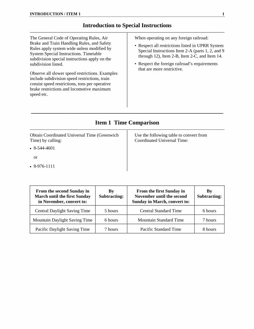
The General Code of Operating Rules, Air Brake and Train Handling Rules, and Safety Rules apply system wide unless modified by System Special Instructions. Timetable subdivision special instructions apply on the subdivision listed. Observe all slower speed restrictions. Examples include subdivision speed restrictions, train consist speed restrictions, tons per operative brake restrictions and locomotive maximum speed etc.
When operating on any foreign railroad:
• Respect all restrictions listed in UPRR System Special Instructions Item 2-A (parts 1, 2, and 9 through 12), Item 2-B, Item 2-C, and Item 14.
• Respect the foreign railroad’s requirements that are more restrictive.
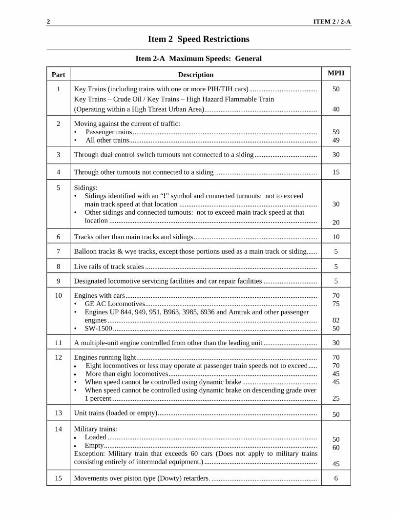
1 Key Trains (including trains with one or more PIH/TIH cars) ...................................... Key Trains – Crude Oil / Key Trains – High Hazard Flammable Train (Operating within a High Threat Urban Area) ...............................................................
50
40
2 Moving against the current of traffic: • Passenger trains ....................................................................................................... • All other trains .........................................................................................................
59 49
3
Through dual control switch turnouts not connected to a siding ...................................
30
4
Through other turnouts not connected to a siding .........................................................
15
5
Sidings: • Sidings identified with an “!” symbol and connected turnouts: not to exceed
main track speed at that location ............................................................................. • Other sidings and connected turnouts: not to exceed main track speed at that
6 Tracks other than main tracks and sidings .....................................................................
10
7
Balloon tracks & wye tracks, except those portions used as a main track or siding ......
5
8
Live rails of track scales ................................................................................................
5
9
Designated locomotive servicing facilities and car repair facilities ..............................
5
10
Engines with cars ........................................................................................................... • GE AC Locomotives ................................................................................................ • Engines UP 844, 949, 951, B963, 3985, 6936 and Amtrak and other passenger
A multiple-unit engine controlled from other than the leading unit ..............................
30
12
Engines running light ..................................................................................................... • Eight locomotives or less may operate at passenger train speeds not to exceed ..... • More than eight locomotives ................................................................................... • When speed cannot be controlled using dynamic brake .......................................... • When speed cannot be controlled using dynamic brake on descending grade over
13 Unit trains (loaded or empty) .........................................................................................
50
14
Military trains: • Loaded ..................................................................................................................... • Empty ....................................................................................................................... Exception: Military train that exceeds 60 cars (Does not apply to military trains consisting entirely of intermodal equipment.) ...............................................................
50 60
45
15 Movements over piston type (Dowty) retarders. ...........................................................
6
ITEM 2-B 3
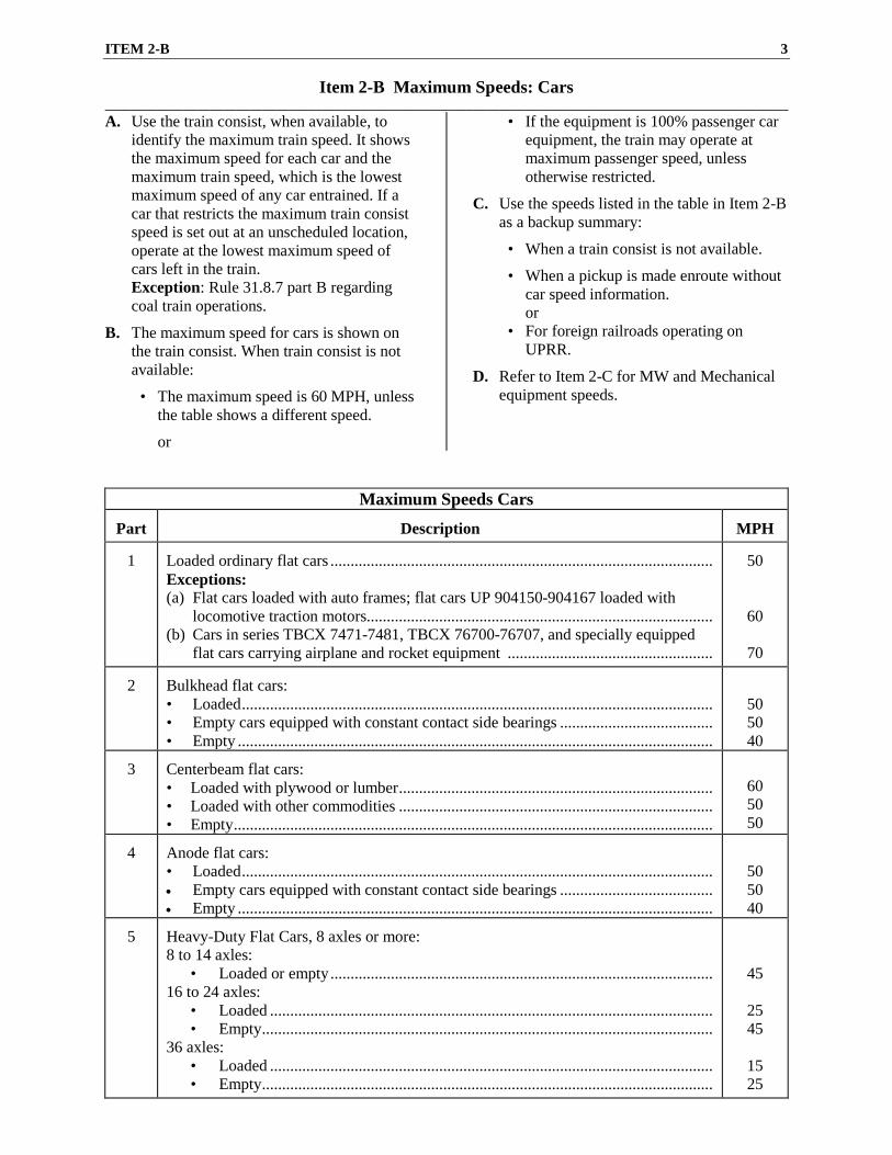
Item 2-B Maximum Speeds: Cars ________________________________________________________________________________________________________ A. Use the train consist, when available, to
identify the maximum train speed. It shows the maximum speed for each car and the maximum train speed, which is the lowest maximum speed of any car entrained. If a car that restricts the maximum train consist speed is set out at an unscheduled location, operate at the lowest maximum speed of cars left in the train. Exception: Rule 31.8.7 part B regarding coal train operations.
B. The maximum speed for cars is shown on the train consist. When train consist is not available:
• The maximum speed is 60 MPH, unless the table shows a different speed.
or
• If the equipment is 100% passenger car equipment, the train may operate at maximum passenger speed, unless otherwise restricted.
C. Use the speeds listed in the table in Item 2-B as a backup summary:
• When a train consist is not available.
• When a pickup is made enroute without car speed information.
or • For foreign railroads operating on
UPRR.
D. Refer to Item 2-C for MW and Mechanical equipment speeds.
Maximum Speeds Cars Part
Description
MPH
1
Loaded ordinary flat cars ............................................................................................... Exceptions: (a) Flat cars loaded with auto frames; flat cars UP 904150-904167 loaded with
locomotive traction motors...................................................................................... (b) Cars in series TBCX 7471-7481, TBCX 76700-76707, and specially equipped
flat cars carrying airplane and rocket equipment ...................................................
50
60
70
2 Bulkhead flat cars: • Loaded ..................................................................................................................... • Empty cars equipped with constant contact side bearings ...................................... • Empty ......................................................................................................................
50 50 40
3
Centerbeam flat cars: • Loaded with plywood or lumber .............................................................................. • Loaded with other commodities .............................................................................. • Empty .......................................................................................................................
60 50 50
4
Anode flat cars: • Loaded ..................................................................................................................... • Empty cars equipped with constant contact side bearings ...................................... • Empty ......................................................................................................................
50 50 40
5
Heavy-Duty Flat Cars, 8 axles or more: 8 to 14 axles:
• Loaded or empty ............................................................................................... 16 to 24 axles:
Exceptions: (a) Loaded multi-platform/unit/well cars ..................................................................... (b) Empty well cars and empty articulated spine cars for carrying trailers and/or
containers ................................................................................................................ (c) Intermodal flat cars made from box cars in series SP 520583-520727, CP 520350-520386 and empty NS 157000-157849 ................................................ (d) Loaded intermodal flat cars made from box cars in series NS 157000-157849 ..... (e) Flat cars in series DRGW 4015-4071, DRGW 21502-21547,
• Loaded ............................................................................................................... • Loaded with coal ............................................................................................... • Empty ................................................................................................................ • Loaded cars in series CTRN 601001 – 601600 and 602001 – 602920 unless
train consist indicates a higher speed ................................................................ Exception: Empty cars having constant contact side bearings or center plate extension pads ........
60 50 50
40
60
8 Gondola cars .................................................................................................................. Exceptions: (a) Empty car in series EJE 4000-4549, EJE 4800-4874,
CR 607000-607480, UP 66800-67649, SP 337700-338099, MRL 38000-38071 and MRL 80511-81332 except if equipped with constant contact side bearings ....
(b) Loaded cars in series UP 903084-903094; cars with initials UP, WP, MP or GONX loaded with aluminum ingots and empty gondolas having constant contact side bearings or center plate extension pads ..............................................
(c) Covered coil gondolas equipped with constant contact side bearings ...................
50
40
60 70
9
Gondola or open-top hopper cars used to haul ore ........................................................
50
10
Covered hopper cars in car series TGSX 443401-443700 and CGAX 9001-9505 .......
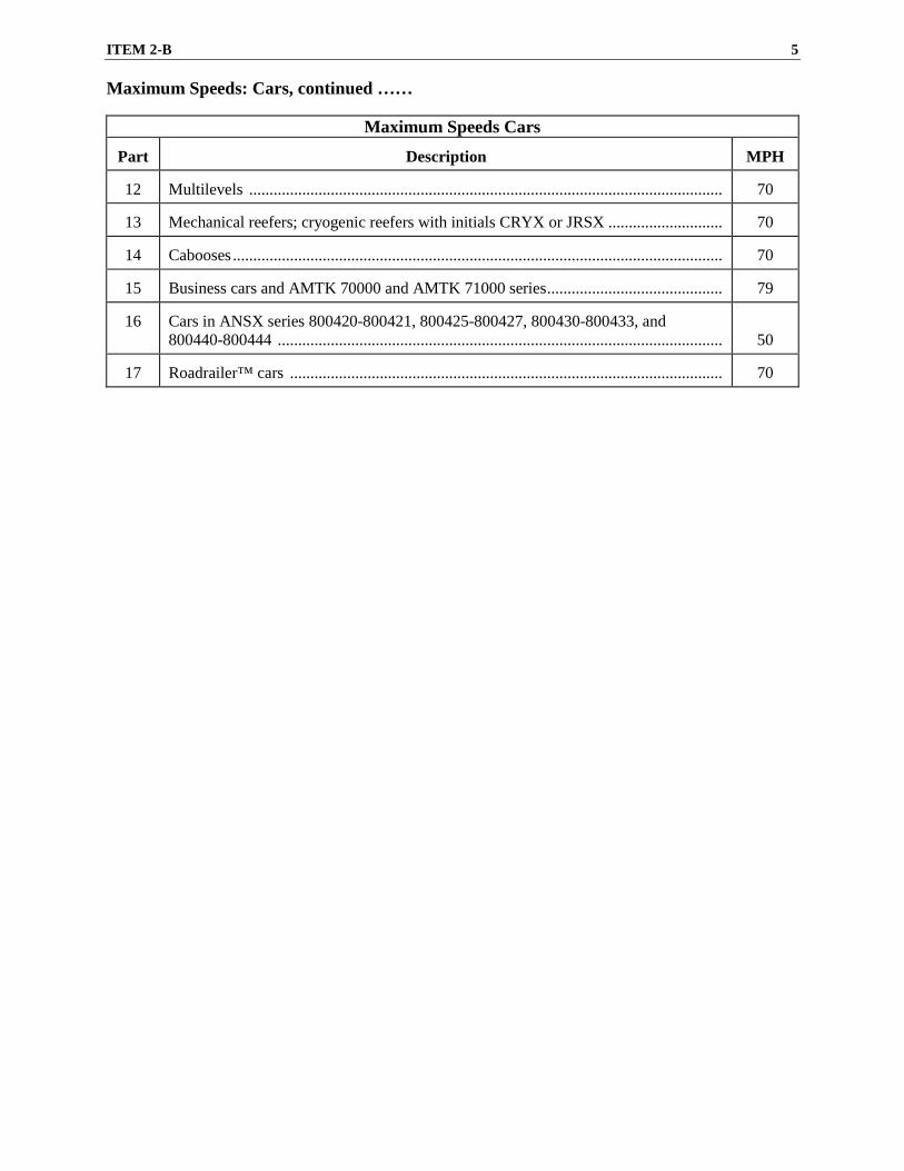
Business cars and AMTK 70000 and AMTK 71000 series ...........................................
79
16
Cars in ANSX series 800420-800421, 800425-800427, 800430-800433, and 800440-800444 .............................................................................................................
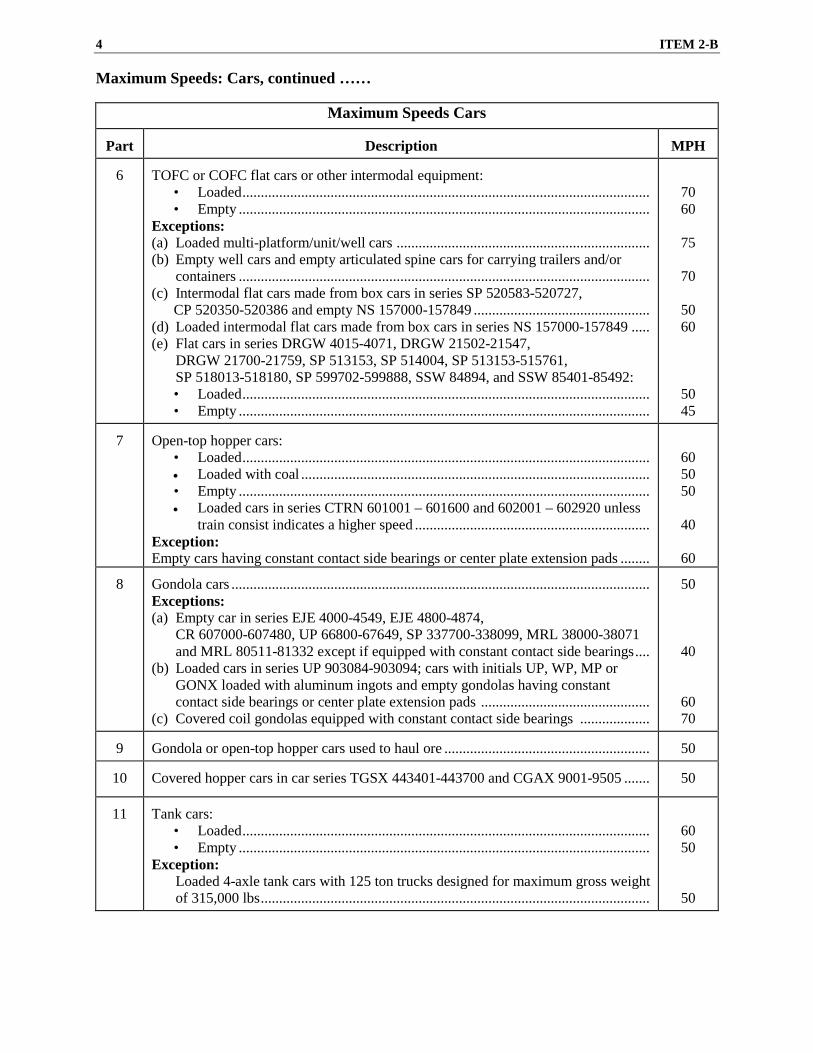
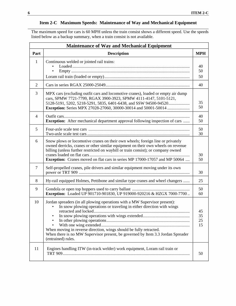
Item 2-C Maximum Speeds: Maintenance of Way and Mechanical Equipment ________________________________________________________________________________________________________
The maximum speed for cars is 60 MPH unless the train consist shows a different speed. Use the speeds listed below as a backup summary, when a train consist is not available.
Loram rail train (loaded or empty) ................................................................................
40 50 50
2
Cars in series RGAX 25000-25049...............................................................................
40
3
MPX cars (excluding outfit cars and locomotive cranes), loaded or empty air dump cars, SPMW 7721-7799, RGAX 3900-3923, SPMW 4111-4147, 5101-5121, 5128-5191, 5202, 5218-5291, 5835, 6401-6438, and SSW 94500-94520 .................... Exception: Series MPX 27028-27060, 30000-30014 and 50001-50014 .....................
35 50
4
Outfit cars ...................................................................................................................... Exception: After mechanical department approval following inspection of cars ......
40 50
5
Four-axle scale test cars ............................................................................................... Two-axle scale test cars ................................................................................................
50 30
6
Snow plows or locomotive cranes on their own wheels; foreign line or privately owned derricks, cranes or other similar equipment on their own wheels on revenue billing (unless further restricted on waybill or train consist); or company owned cranes loaded on flat cars .............................................................................................. Exception: Cranes moved on flat cars in series MP 17000-17057 and MP 50064 ....
30 50
7
Self-propelled cranes, pile drivers and similar equipment moving under its own power or TRT 909 ........................................................................................................
30
8 Hy-rail equipped Holmes, Pettibone and similar type cranes and wheel changers ......
25
9
Gondola or open top hoppers used to carry ballast ...................................................... Exception: Loaded UP 901710-901830, UP 919000-920216 & HZGX 7000-7700 ..
50 60
10
Jordan spreaders (in all plowing operations with a MW Supervisor present):
• In snow plowing operations or traveling in either direction with wings retracted and locked ..........................................................................................
• In snow plowing operations with wings extended ............................................ • In other plowing operations .............................................................................. • With one wing extended ...................................................................................
When moving in reverse direction, wings should be fully retracted. When there is no MW Supervisor present, be governed by Item 3.3 Jordan Spreader (entrained) rules.
45 35 25 15
11
Engines handling ITW (in-track welder) work equipment, Loram rail train or TRT 909 .......................................................................................................................
50
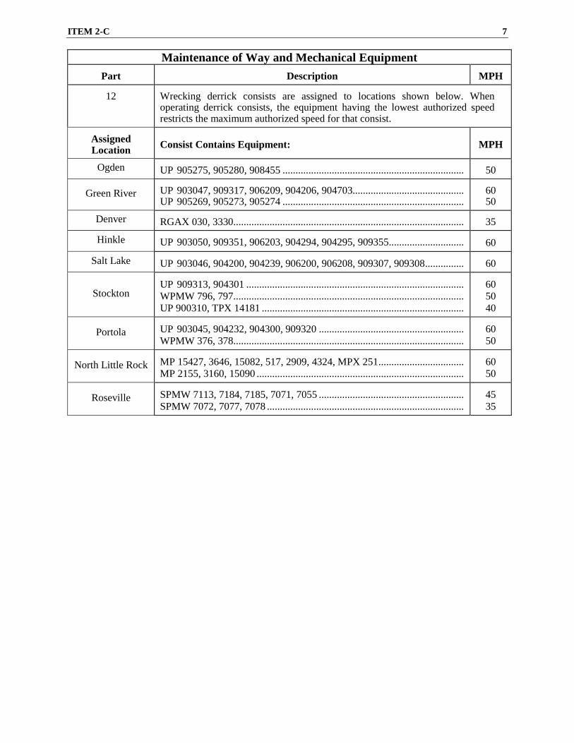
ITEM 2-C 7
Maintenance of Way and Mechanical Equipment
Part
Description MPH
12
Wrecking derrick consists are assigned to locations shown below. When operating derrick consists, the equipment having the lowest authorized speed restricts the maximum authorized speed for that consist.
Assigned Location
Consist Contains Equipment:
MPH
Ogden UP 905275, 905280, 908455 ......................................................................
50
Green River UP 903047, 909317, 906209, 904206, 904703........................................... UP 905269, 905273, 905274 ......................................................................
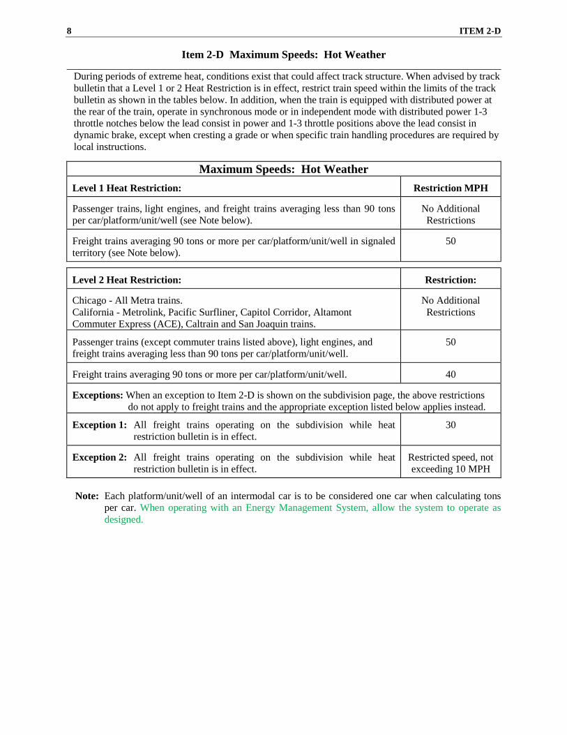
Item 2-D Maximum Speeds: Hot Weather ________________________________________________________________________________________________________
During periods of extreme heat, conditions exist that could affect track structure. When advised by track bulletin that a Level 1 or 2 Heat Restriction is in effect, restrict train speed within the limits of the track bulletin as shown in the tables below. In addition, when the train is equipped with distributed power at the rear of the train, operate in synchronous mode or in independent mode with distributed power 1-3 throttle notches below the lead consist in power and 1-3 throttle positions above the lead consist in dynamic brake, except when cresting a grade or when specific train handling procedures are required by local instructions.
Maximum Speeds: Hot Weather Level 1 Heat Restriction:
Restriction MPH
Passenger trains, light engines, and freight trains averaging less than 90 tons per car/platform/unit/well (see Note below).
No Additional Restrictions
Freight trains averaging 90 tons or more per car/platform/unit/well in signaled territory (see Note below).
50
Level 2 Heat Restriction:
Restriction:
Chicago - All Metra trains. California - Metrolink, Pacific Surfliner, Capitol Corridor, Altamont Commuter Express (ACE), Caltrain and San Joaquin trains.
No Additional Restrictions
Passenger trains (except commuter trains listed above), light engines, and freight trains averaging less than 90 tons per car/platform/unit/well.
50
Freight trains averaging 90 tons or more per car/platform/unit/well.
40
Exceptions: When an exception to Item 2-D is shown on the subdivision page, the above restrictions
do not apply to freight trains and the appropriate exception listed below applies instead. Exception 1: All freight trains operating on the subdivision while heat
restriction bulletin is in effect.
30
Exception 2: All freight trains operating on the subdivision while heat
restriction bulletin is in effect.
Restricted speed, not exceeding 10 MPH
Note: Each platform/unit/well of an intermodal car is to be considered one car when calculating tons
per car. When operating with an Energy Management System, allow the system to operate as designed.
ITEM 2-E 9
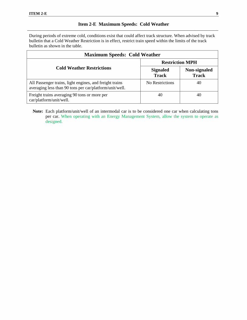
Item 2-E Maximum Speeds: Cold Weather _________________________________________________________________________________________________________
During periods of extreme cold, conditions exist that could affect track structure. When advised by track bulletin that a Cold Weather Restriction is in effect, restrict train speed within the limits of the track bulletin as shown in the table.
Maximum Speeds: Cold Weather
Cold Weather Restrictions Restriction MPH
Signaled Track
Non-signaled Track
All Passenger trains, light engines, and freight trains averaging less than 90 tons per car/platform/unit/well.
No Restrictions 40
Freight trains averaging 90 tons or more per car/platform/unit/well.
40 40
Note: Each platform/unit/well of an intermodal car is to be considered one car when calculating tons
per car. When operating with an Energy Management System, allow the system to operate as designed.
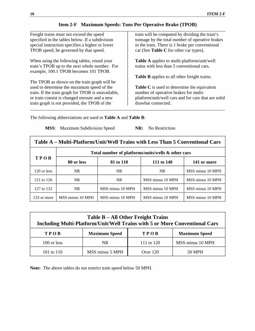
10 ITEM 2-F
Item 2-F Maximum Speeds: Tons Per Operative Brake (TPOB) ________________________________________________________________________________________________________ Freight trains must not exceed the speed specified in the tables below. If a subdivision special instruction specifies a higher or lower TPOB speed, be governed by that speed. When using the following tables, round your train’s TPOB up to the next whole number. For example, 100.1 TPOB becomes 101 TPOB. The TPOB as shown on the train graph will be used to determine the maximum speed of the train. If the train graph for TPOB is unavailable, or train consist is changed enroute and a new train graph is not provided, the TPOB of the
train will be computed by dividing the train’s tonnage by the total number of operative brakes in the train. There is 1 brake per conventional car (See Table C for other car types). Table A applies to multi-platform/unit/well trains with less than 5 conventional cars. Table B applies to all other freight trains. Table C is used to determine the equivalent number of operative brakes for multi-platform/unit/well cars and for cars that are solid drawbar connected.
_____________________________________________________________________________________ The following abbreviations are used in Table A and Table B:
MSS: Maximum Subdivision Speed NR: No Restriction
Table A – Multi-Platform/Unit/Well Trains with Less Than 5 Conventional Cars T P O B
Total number of platforms/units/wells & other cars
80 or less
81 to 110
111 to 140
141 or more
120 or less
NR
NR
NR
MSS minus 10 MPH
121 to 126
NR
NR
MSS minus 10 MPH
MSS minus 10 MPH
127 to 132
NR
MSS minus 10 MPH
MSS minus 10 MPH
MSS minus 10 MPH
133 or more
MSS minus 10 MPH
MSS minus 10 MPH
MSS minus 10 MPH
MSS minus 10 MPH
Table B – All Other Freight Trains Including Multi-Platform/Unit/Well Trains with 5 or More Conventional Cars
T P O B
Maximum Speed
T P O B
Maximum Speed
100 or less
NR
111 to 120
MSS minus 10 MPH
101 to 110
MSS minus 5 MPH
Over 120
50 MPH
Note: The above tables do not restrict train speed below 50 MPH.
ITEM 2-F 11
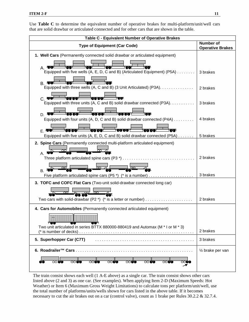
Use Table C to determine the equivalent number of operative brakes for multi-platform/unit/well cars that are solid drawbar or articulated connected and for other cars that are shown in the table.
Table C - Equivalent Number of Operative Brakes Type of Equipment (Car Code) Number of
Operative Brakes
1. Well Cars (Permanently connected solid drawbar or articulated equipment)
A. Equipped with five wells (A, E, D, C and B) (Articulated Equipment) (P5A) . . . . . . . .
B. Equipped with three wells (A, C and B) (3 Unit Articulated) (P3A). . . . . . . . . . . . . . .
C. Equipped with three units (A, C and B) solid drawbar connected (P3A). . . . . . . . . . .
D. Equipped with four units (A, D, C and B) solid drawbar connected (P4A) . . . . . . . . .
E. Equipped with five units (A, E, D, C and B) solid drawbar connected (P5A) . . . . . . .
The train consist shows each well (1 A-E above) as a single car. The train consist shows other cars listed above (2 and 3) as one car. (See examples). When applying Item 2-D (Maximum Speeds: Hot Weather) or Item 6 (Maximum Gross Weight Limitations) to calculate tons per platform/unit/well, use the total number of platforms/units/wells shown for cars listed in the above table. If it becomes necessary to cut the air brakes out on a car (control valve), count as 1 brake per Rules 30.2.2 & 32.7.4.
TTX
12 ITEM 2-F
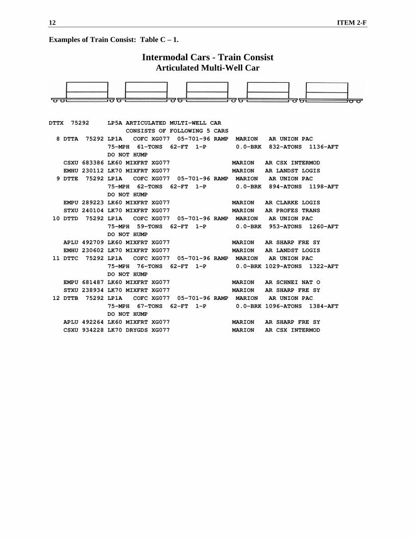
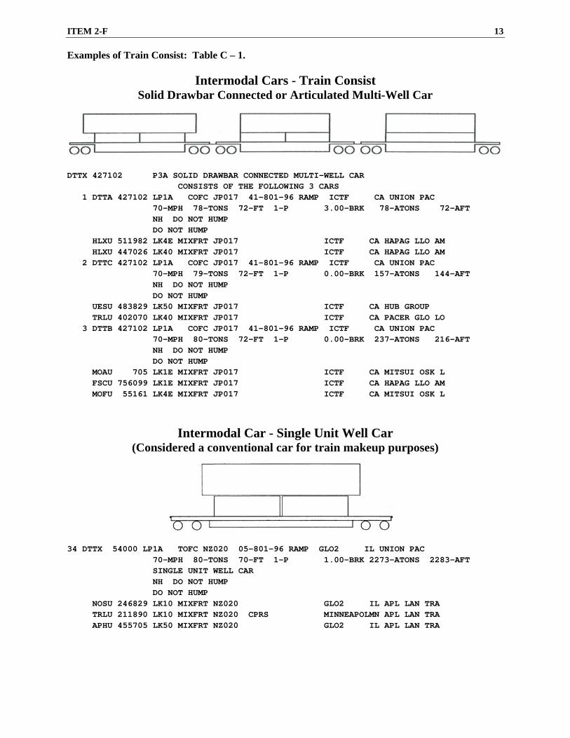
Examples of Train Consist: Table C – 1.
Intermodal Cars - Train Consist Articulated Multi-Well Car
DTTX 75292 LP5A ARTICULATED MULTI-WELL CAR CONSISTS OF FOLLOWING 5 CARS 8 DTTA 75292 LP1A COFC XG077 05-701-96 RAMP MARION AR UNION PAC 75-MPH 61-TONS 62-FT 1-P 0.0-BRK 832-ATONS 1136-AFT DO NOT HUMP CSXU 683386 LK60 MIXFRT XG077 MARION AR CSX INTERMOD EMHU 230112 LK70 MIXFRT XG077 MARION AR LANDST LOGIS 9 DTTE 75292 LP1A COFC XG077 05-701-96 RAMP MARION AR UNION PAC 75-MPH 62-TONS 62-FT 1-P 0.0-BRK 894-ATONS 1198-AFT DO NOT HUMP EMPU 289223 LK60 MIXFRT XG077 MARION AR CLARKE LOGIS STXU 240104 LK70 MIXFRT XG077 MARION AR PROFES TRANS 10 DTTD 75292 LP1A COFC XG077 05-701-96 RAMP MARION AR UNION PAC 75-MPH 59-TONS 62-FT 1-P 0.0-BRK 953-ATONS 1260-AFT DO NOT HUMP APLU 492709 LK60 MIXFRT XG077 MARION AR SHARP FRE SY EMHU 230602 LK70 MIXFRT XG077 MARION AR LANDST LOGIS 11 DTTC 75292 LP1A COFC XG077 05-701-96 RAMP MARION AR UNION PAC 75-MPH 76-TONS 62-FT 1-P 0.0-BRK 1029-ATONS 1322-AFT DO NOT HUMP EMPU 681487 LK60 MIXFRT XG077 MARION AR SCHNEI NAT O STXU 238934 LK70 MIXFRT XG077 MARION AR SHARP FRE SY 12 DTTB 75292 LP1A COFC XG077 05-701-96 RAMP MARION AR UNION PAC 75-MPH 67-TONS 62-FT 1-P 0.0-BRK 1096-ATONS 1384-AFT DO NOT HUMP APLU 492264 LK60 MIXFRT XG077 MARION AR SHARP FRE SY CSXU 934228 LK70 DRYGDS XG077 MARION AR CSX INTERMOD
ITEM 2-F 13
Examples of Train Consist: Table C – 1.
Intermodal Cars - Train Consist Solid Drawbar Connected or Articulated Multi-Well Car
DTTX 427102 P3A SOLID DRAWBAR CONNECTED MULTI-WELL CAR CONSISTS OF THE FOLLOWING 3 CARS 1 DTTA 427102 LP1A COFC JP017 41-801-96 RAMP ICTF CA UNION PAC 70-MPH 78-TONS 72-FT 1-P 3.00-BRK 78-ATONS 72-AFT NH DO NOT HUMP DO NOT HUMP HLXU 511982 LK4E MIXFRT JP017 ICTF CA HAPAG LLO AM HLXU 447026 LK40 MIXFRT JP017 ICTF CA HAPAG LLO AM 2 DTTC 427102 LP1A COFC JP017 41-801-96 RAMP ICTF CA UNION PAC 70-MPH 79-TONS 72-FT 1-P 0.00-BRK 157-ATONS 144-AFT NH DO NOT HUMP DO NOT HUMP UESU 483829 LK50 MIXFRT JP017 ICTF CA HUB GROUP TRLU 402070 LK40 MIXFRT JP017 ICTF CA PACER GLO LO 3 DTTB 427102 LP1A COFC JP017 41-801-96 RAMP ICTF CA UNION PAC 70-MPH 80-TONS 72-FT 1-P 0.00-BRK 237-ATONS 216-AFT NH DO NOT HUMP DO NOT HUMP MOAU 705 LK1E MIXFRT JP017 ICTF CA MITSUI OSK L FSCU 756099 LK1E MIXFRT JP017 ICTF CA HAPAG LLO AM MOFU 55161 LK4E MIXFRT JP017 ICTF CA MITSUI OSK L
Intermodal Car - Single Unit Well Car (Considered a conventional car for train makeup purposes)
34 DTTX 54000 LP1A TOFC NZ020 05-801-96 RAMP GLO2 IL UNION PAC 70-MPH 80-TONS 70-FT 1-P 1.00-BRK 2273-ATONS 2283-AFT SINGLE UNIT WELL CAR NH DO NOT HUMP DO NOT HUMP NOSU 246829 LK10 MIXFRT NZ020 GLO2 IL APL LAN TRA TRLU 211890 LK10 MIXFRT NZ020 CPRS MINNEAPOLMN APL LAN TRA APHU 455705 LK50 MIXFRT NZ020 GLO2 IL APL LAN TRA
14 ITEM 2-F
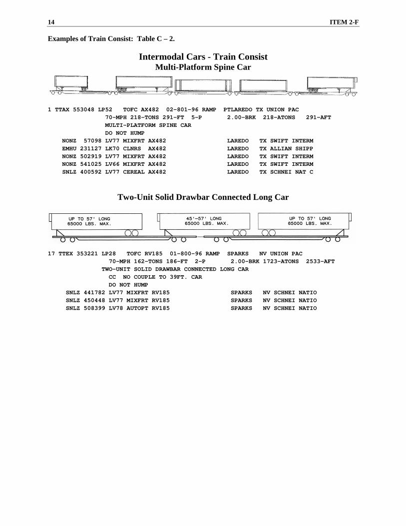
Examples of Train Consist: Table C – 2.
Intermodal Cars - Train Consist Multi-Platform Spine Car
1 TTAX 553048 LP52 TOFC AX482 02-801-96 RAMP PTLAREDO TX UNION PAC 70-MPH 218-TONS 291-FT 5-P 2.00-BRK 218-ATONS 291-AFT MULTI-PLATFORM SPINE CAR DO NOT HUMP NONZ 57098 LV77 MIXFRT AX482 LAREDO TX SWIFT INTERM EMHU 231127 LK70 CLNRS AX482 LAREDO TX ALLIAN SHIPP NONZ 502919 LV77 MIXFRT AX482 LAREDO TX SWIFT INTERM NONZ 541025 LV66 MIXFRT AX482 LAREDO TX SWIFT INTERM SNLZ 400592 LV77 CEREAL AX482 LAREDO TX SCHNEI NAT C
Two-Unit Solid Drawbar Connected Long Car
17 TTEX 353221 LP28 TOFC RV185 01-800-96 RAMP SPARKS NV UNION PAC 70-MPH 162-TONS 186-FT 2-P 2.00-BRK 1723-ATONS 2533-AFT TWO-UNIT SOLID DRAWBAR CONNECTED LONG CAR CC NO COUPLE TO 39FT. CAR DO NOT HUMP SNLZ 441782 LV77 MIXFRT RV185 SPARKS NV SCHNEI NATIO SNLZ 450448 LV77 MIXFRT RV185 SPARKS NV SCHNEI NATIO SNLZ 508399 LV78 AUTOPT RV185 SPARKS NV SCHNEI NATIO
ITEM 3 15
Item 3 Trains Handling Company Equipment ________________________________________________________________________________________________________
1. Rail Trains
Equipment for handling continuous-welded rail, or continuous lengths of bolted rail, consists of permanently coupled flat cars. Couplers are blocked against slack and are highly susceptible to damage from rough handling.
Buffer Cars
When equipment is loaded with rail, a buffer car is used at each end. The buffer car must not be a car containing hazardous materials or an occupied caboose or camp car. The ends of the buffer car must be at least as tall as the top row of rail to restrain the rail. The “B” end of the buffer car must not be next to the equipment loaded with rail. However, the rail train supervisor may authorize loaded equipment to be operated without a buffer to/from an unloading/loading site.
Exception: Trains LR1-50, LR2-50 and LR3-50 will utilize their attached bulkhead doors on each end to restrain rail.
Do Not Combine Rail Trains
Do not combine rail trains with other traffic. However, a Chief Engineer may authorize an empty rail train to be placed on the rear of a manifest train. A Chief Engineer may also authorize handling outfit cars and cars of track material or related items, not exceeding 70 cars, behind the CWR equipment.
Do not combine two CWR rail train sets on the following territories unless authorized by a Chief Engineer: • Western Region • Colorado Springs Subdivision • Alamosa Subdivision • Moffat Tunnel Subdivision • Glenwood Springs Subdivision • North Fork Subdivision • Craig Subdivision • Tennessee Pass Subdivision or • Any track with curvature exceeding six
degrees.
Loram Rail Train Do not handle Loram rail train on any territory with curvature exceeding 16 degrees.
Movements of Loaded Rail Trains Do not move loaded rail trains without authority from:
• The MW supervisor in charge of the rail train.
or
• MW train management. The MW supervisor must accompany rail trains during loading and unloading operations. The MW supervisor is not required to accompany rail train movements to/from an unloading/loading site. When accompanied by a MW supervisor, train and engine crews must be alert for any signal or instruction from the MW supervisor. Before releasing a loaded rail train, the MW supervisor must ensure all rails are properly secured and buffer cars are in place. Bad-ordered and/or Separated Equipment If any rail trains or support equipment have been bad-ordered and/or separated from their mated car(s), the Maintenance of Way Operations Control (MWOC) Desk (402) 636-7434, must be notified immediately and the remainder of the rail train or support equipment should stay (as a unit) at that location until the repair is complete. The rail train manager must be notified if necessary repairs will require the rail train to be delayed more than 24 hours. The rail train manager can be contacted through the MWOC Desk.
Rail Pick-up Units - Sets of Three LMIX701003/04/05 (Loram)
Rail Pick-up Units - Sets of Four MP6800/MP6801/MP6802/MP6803 MP6804/MP6805/MP6806/MP6807 SPMW6650/SPMW6651/SPMW6652/ SPMW6653
Rail Pick-up Units - Sets of Five MP6864/MP6865/MP6866/MP6867/ MP6868 SPMW5398/SPMW5399/SPMW5401/ SPMW5403/SPMW5397 UP904563/UP904564/UP904565/ UP904566/UP904567
2. Wrecking Derricks, Locomotive Cranes and Similar Equipment
Secure booms on wrecking derricks, locomotive cranes and similar equipment. Booms must be trailing or detached unless they are in work train service. A mechanical employee will accompany the wrecking derrick. A crane operator will accompany locomotive cranes and must ride either:
• In the crane.
• On the train that has the crane entrained.
or
• In a nearby vehicle having radio communications.
Inspect cranes at the following locations:
• Before leaving the initial terminal.
• Within 50 miles of the initial terminal.
• Within each 100 miles afterward.
During the inspection, ensure:
• Crane is headed in the right direction.
• Boom is properly secured.
• Equipment is being handled at the proper speed.
Booms must be disconnected on cranes, unless boom rest car specifically designed to enable the crane to move with the boom attached accompanies the crane. However, if the boom cannot be disconnected and cannot be in the trailing position, the train may be moved only as follows:
• Train management or an operating manager must authorize the movement.
• A crane operator must accompany the crane.
• Speed must not exceed: − 15 MPH if the crane operator is not riding
the crane. − 30 MPH if the crane operator is riding the
crane.
• Movement may only be made to the first location where it can be turned.
Placement in train: • Place derricks and cranes within 10 cars of
the engine and not ahead of more than 8000 tons.
• Place wrecking derrick consists as close to the rear of the train as possible and not ahead of more than 4000 tons.
The above restrictions do not apply to cranes loaded on flat cars, series MP 17000-17057, and MP 50064. These cranes may operate at 50 MPH. They may also operate with the boom in the non-trailing position, if properly secured.
3. Jordan Spreaders (entrained)
Head Jordan Spreaders in the direction the train is moving, unless in work trains. Inspect equipment carefully before moving, and frequently enroute. When entrained:
• Operate with wings always retracted, locked and secured with chain or cable.
• Maximum speeds:
− 35 MPH forward. − 15 MPH reverse.*
• Only move in reverse direction to the first location machine can be turned.*
• Must be handled on the rear of train.*
ITEM 3 17
* Exception: Upon instruction from the MW supervisor, Jordan Spreaders entrained in work trains may be moved in reverse, to the designated location, at the speed authorized by the MW supervisor.
4. Snow Plows
Handle one-way (multiple track) and wedge (single track) snow plows as follows:
• When deadheading the plow and snow is not above the top of the rail, locate the plow in trailing position on the rear of freight trains.
• When deadheading the plow and snow is above the top of the rail, locate the plow in leading position immediately ahead of the lead locomotive.
• When plowing snow, locate the plow in leading position immediately ahead of the lead locomotive. Do not pull a train when plowing snow.
• Do not operate snow plows through drifts when trains are approaching or passing on an adjacent track.
• Raise flangers when passing over bridges, highway crossings, railroad crossings, track car set-offs, high guardrails, frogs, switches, and when passing through interlocking limits.
• Handle rotary snow plows in special trains or on the rear of freight trains with rotary blades in the trailing position.
• In switching movements, handle a snow plow alone or with only one car.
5. Two-axle Scale Test Cars
Handle two-axle scale test cars in a train immediately ahead of the rear car. Scale test cars must not be placed next to any loaded car containing hazardous materials. Handle two-axle scale test cars in separate trains if moving more than one.
6. Passenger, Business, and Outfit Cars
Train management may specifically instruct handling passenger, business and outfit cars differently than listed below. Do not handle passenger, business, or outfit cars while switching. In freight trains, handle:
• Outfit cars on the head end.
• Passenger and business cars on the rear end.
When handling passenger or business cars on the rear end of a freight train, comply with the following:
• Limit bulk commodity unit trains and trains consisting entirely of multi-platform/unit/well cars to a maximum of three passenger and/or business cars.
• Limit all other trains to a maximum of two passenger and/or business cars. In addition, trains must not:
− Contain more than 20 multilevel cars.
− Exceed 6000 feet (including locomotives and passenger and/or business cars).
If train management authorizes handling passenger or business cars on the head end of a freight train, comply with the following:
• A maximum of five of these cars may be entrained.
• When handling two or more of these cars, if trailing tonnage behind these cars exceeds 3500 tons, separate these cars from each other by at least two loaded freight cars.
• Handle business cars UPP 106 (Shoshone) UPP 115 (Selma), UPP 203 (Idaho), and UPP 420 (Fox River) only on the rear of freight trains.
• Handle business cars UPP 210, UPP 252, EMDX 820, and EMDX 840 (mobile laboratory cars) at any location in freight trains.
7. Ballast Cars with Air Operated Ballast Gates
The following cars are ballast cars equipped with air operated gates and an independent ballast air system:
• UP 901660-901830.
• UP 901900-901949.
• UP 901991-901999.
• UP 919000-920311.
Do the following to make the ballast air system inoperative when these cars are loaded and in transit:
• Stop the air supply to the ballast air system.
• Bleed the ballast air system reservoirs by opening an air drain valve on the ballast reservoirs, located on the "A" end of the car.
• Leave the ballast air line angle cocks open.
18 ITEM 3
Before using the ballast air system, close all ballast reservoir drain valves. Charge the system only during short work train moves to an unloading site and during actual ballast unloading.
8. Engines Handling ITW (In-Track Welder)
• Employee in charge may impose more restrictive speed restrictions.
• ITW work equipment is equipped with independent air brakes.
• Employees in charge will occupy ITW and have control of the air brakes and have radio communication with the engineer.
• ITW is towed with a solid hitch and must not be placed in a train or handled with any other equipment.
• ITW is equipped with marker on rear.
9. Unmanned Geometry Measurement System (UGMS) UP 910701
• Do not kick or hump. • Must be the head car in the train.
ITEM 4 19
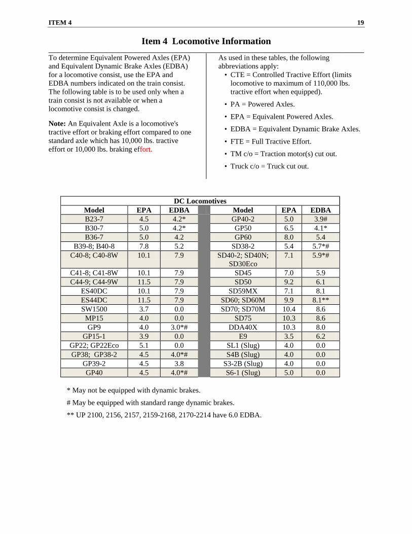
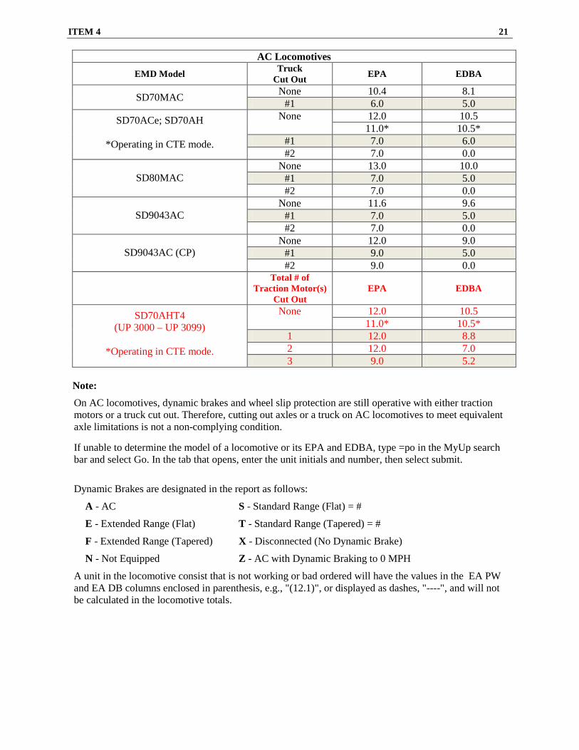
Item 4 Locomotive Information ________________________________________________________________________________________________________ To determine Equivalent Powered Axles (EPA) and Equivalent Dynamic Brake Axles (EDBA) for a locomotive consist, use the EPA and EDBA numbers indicated on the train consist. The following table is to be used only when a train consist is not available or when a locomotive consist is changed. Note: An Equivalent Axle is a locomotive's tractive effort or braking effort compared to one standard axle which has 10,000 lbs. tractive effort or 10,000 lbs. braking effort.
As used in these tables, the following abbreviations apply:
• CTE = Controlled Tractive Effort (limits locomotive to maximum of 110,000 lbs. tractive effort when equipped).
• PA = Powered Axles.
• EPA = Equivalent Powered Axles.
• EDBA = Equivalent Dynamic Brake Axles.
• FTE = Full Tractive Effort.
• TM c/o = Traction motor(s) cut out.
• Truck c/o = Truck cut out.
DC Locomotives Model EPA EDBA Model EPA EDBA B23-7 4.5 4.2* GP40-2 5.0 3.9# B30-7 5.0 4.2* GP50 6.5 4.1* B36-7 5.0 4.2 GP60 8.0 5.4
# May be equipped with standard range dynamic brakes.
** UP 2100, 2156, 2157, 2159-2168, 2170-2214 have 6.0 EDBA.
20 ITEM 4
Note: Traction motor cut out switches.
• DC locomotive traction motors must not be cut out to meet EPA or EDBA limitations. Traction motors may be cut out only when they are defective. Locomotive may be isolated/shut down to meet EPA or EDBA limitations.
• AC locomotive traction motors 1, 2 & 3 may be cut out to meet EPA or EDBA limitations. Traction motors 4, 5 & 6 may only be cut out when defective.
• A tag must be placed on the lead unit and on the unit having the cut out traction motor stating that the traction motor has been cut out for the purpose of meeting equivalent axle restrictions. This is to ensure subsequent crews are aware that all dynamic brakes on that locomotive may be inoperative.
**Foreign line ES44AC and ES44AH locomotives may not be CTE capable.
AC Locomotives
GE Model Total # of Traction Motor(s) Cut Out EPA EDBA
C44AC; C44/60AC; C44ACCCA
None 12.1 9.8 1 11.0 8.0 2 8.0 6.0 3 6.0 5.0
C44AC (CP)
None 12.1 7.8 1 11.0 7.0 2 8.0 5.0 3 6.0 4.0
C6044AC
None 12.1 11.7 1 11.0 10.0 2 8.0 6.0 3 6.0 6.0
C44ACCTE; C45ACCTE; C45AH; ES44AC** & ES44AH**
When in a lead consist or in a remote consist operating in the Full Tractive Effort (FTE) mode.
None
12.1
9.8
*When in a remote consist operating in the Controlled Tractive Effort (CTE) mode.
11.0*
9.8*
1 11.0 8.0 2 8.0 6.0 3 6.0 5.0
CW60AC
None 12.1 11.7 1 12.0 10.0 2 11.0 8.0 3 8.0 6.0
ITEM 4 21
AC Locomotives
EMD Model Truck Cut Out EPA EDBA
SD70MAC None 10.4 8.1 #1 6.0 5.0
SD70ACe; SD70AH
*Operating in CTE mode.
None 12.0 10.5 11.0* 10.5*
#1 7.0 6.0 #2 7.0 0.0
SD80MAC
None 13.0 10.0 #1 7.0 5.0 #2 7.0 0.0
SD9043AC
None 11.6 9.6 #1 7.0 5.0 #2 7.0 0.0
SD9043AC (CP)
None 12.0 9.0 #1 9.0 5.0 #2 9.0 0.0
Total # of Traction Motor(s)
Cut Out EPA EDBA
SD70AHT4 (UP 3000 – UP 3099)
*Operating in CTE mode.
None 12.0 10.5 11.0* 10.5*
1 12.0 8.8 2 12.0 7.0 3 9.0 5.2
Note:
On AC locomotives, dynamic brakes and wheel slip protection are still operative with either traction motors or a truck cut out. Therefore, cutting out axles or a truck on AC locomotives to meet equivalent axle limitations is not a non-complying condition.
If unable to determine the model of a locomotive or its EPA and EDBA, type =po in the MyUp search bar and select Go. In the tab that opens, enter the unit initials and number, then select submit.
Dynamic Brakes are designated in the report as follows:
A - AC S - Standard Range (Flat) = #
E - Extended Range (Flat) T - Standard Range (Tapered) = #
F - Extended Range (Tapered) X - Disconnected (No Dynamic Brake)
N - Not Equipped Z - AC with Dynamic Braking to 0 MPH
A unit in the locomotive consist that is not working or bad ordered will have the values in the EA PW and EA DB columns enclosed in parenthesis, e.g., "(12.1)", or displayed as dashes, "----", and will not be calculated in the locomotive totals.
22 ITEM 5 / 5-A
Item 5 Car Placement and Train Make-Up Restrictions
Item 5-A Shipments of Excessive Height/Width ________________________________________________________________________________________________________
When train length and train make-up requirements permit, position dimensional loads, excess high wide shipments and unusual shipments (including those identified as high value on the consist) that require close attention as close to the engine as possible, but no closer than the sixth car from an occupied engine or caboose. When positioning a shipment, each platform/unit/well of a multi-platform/unit/well car is to be considered as one car.
The following must be considered when placing excessive dimension loads, unusual shipments that require close attention or high value loads:
• Train Make-Up requirements take precedence.
• Equipment requiring handling on the rear end only.
Excessive Dimension Load
The following classes of equipment will be covered by instructions from a Manager Clearances and/or a track bulletin concerning movement:
• Excessive dimension load.
or
• Other unusual shipments that require close attention.
An “Excessive Dimension Load” is any load with a width more than 12 feet. At least twelve hours ahead of the train's departure, local managers must notify Train Management of the train in which they would like to place the excessive dimension load. Excessive dimension loads may only be scheduled to the train by Train Management. Upon Train Management's approval, the train dispatcher will issue a wide load notification track bulletin:
• To the train that will handle the excessive dimension load.
• To trains that may meet, pass or be passed by the train handling the excessive dimension load.
If the conductor does not receive a track bulletin covering such shipments, notify the train dispatcher before moving the train.
Dimensional Load
A “Dimensional Load” is any load with a width of 11 feet 0 inches to 12 feet 0 inches, inclusive, as shown on the train consist. If the consist includes a dimensional load, the conductor must conduct a job briefing with the train dispatcher before moving the train, reviewing all operating restrictions for their route.
The conductor must notify other crew members of the presence of both excessive dimension loads and dimensional loads before movement of the train.
Speed Restricted Areas
Trains handling dimensional or excessive dimension loads must not exceed 30 MPH until load is beyond restricted area. Train dispatcher may authorize normal speed when other trains are not in the area to be met or passed. Restricted areas will be listed in subdivision special instructions.
Special Handling Guidelines for High Wide or High Value Loads
When there are High Wide or High Value Loads in the train that require close attention, these shipments must:
• Be inspected by a Mechanical representative at time of interchange or release from an industry to ensure loads are properly braced and secured for safe, damage-free transportation.
• Be positioned in a train in accordance with system and subdivision special instructions.
• Not remain in a consist during switching operations, except when necessary to properly position the car in train.
• Not be kicked or humped. • Not have other cars kicked or humped
against these loads.
• Have air brake system charged and used when spotting/pulling these loads.
• Be set to a special hold track designated to hold/process such loads at terminals.
ITEM 5-B 23
Item 5-B System Train Make-Up Requirements ________________________________________________________________________________________________________
Train consist information will govern train make-up requirements.
When train consist specifies train type different from train symbol, train will operate as the train type identified on train consist.
Example: QHONL 14 will operate as a bulk train.
TPA and trailing tonnage limits (including tonnage behind entrained helper) shown on train consist must not be exceeded. Tonnage handled by helper(s) must be deducted from total tonnage to determine trailing tonnage behind lead consist.
If an enroute locomotive failure causes the TPA listed on the train consist to be exceeded, train may continue provided maximum TPA for any train category on that route is not exceeded. If the coupler limit is exceeded, one or a combination of the following may be necessary:
• Road power rearranged (Move units from the lead consist to the helper.)
• Add power to the helper.
• Add additional helper consist.
or
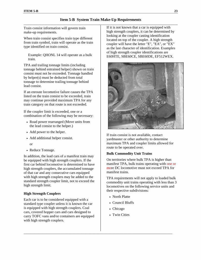
• Reduce Tonnage. In addition, the lead cars of a manifest train may be equipped with high strength couplers. If the first car behind locomotive is determined to have high strength couplers, the accumulated tonnage of that car and any consecutive cars equipped with high strength couplers may be added to the standard strength coupler limit, not to exceed the high strength limit. High Strength Couplers
Each car is to be considered equipped with a standard type coupler unless it is known the car is equipped with high strength couplers. Coal cars, covered hopper cars and cars designed to carry TOFC vans and/or containers are equipped with high strength couplers.
If it is not known that a car is equipped with high strength couplers, it can be determined by looking at the coupler casting identification located on top of the coupler. A high strength coupler will have the letter "E", "EA", or "EX" as the last character of identification. Examples of high strength coupler identifications are E60HTE, SBE60CE, SBE60DE, EF512WEX.
If train consist is not available, contact yardmaster or other authority to determine maximum TPA and coupler limits allowed for route to be operated over.
Bulk Commodity Unit Trains
On territories where bulk TPA is higher than manifest TPA, bulk trains operating with one or more DC locomotive must not exceed TPA for manifest trains.
TPA requirements will not apply to loaded bulk commodity unit trains operating with less than 3 locomotives on the following service units and their respective subdivisions:
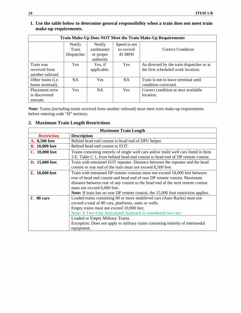
1. Use the table below to determine general responsibility when a train does not meet train make-up requirements.
Train Make-Up Does NOT Meet the Train Make-Up Requirements
Notify Train
Dispatcher
Notify yardmaster or proper authority
Speed is not to exceed 45 MPH
Correct Condition
Train was received from another railroad.
Yes Yes, if applicable.
Yes As directed by the train dispatcher or at the first scheduled work location.
Other trains (i.e. home terminal).
NA Yes NA Train is not to leave terminal until condition corrected.
Placement error is discovered enroute.
Yes NA Yes Correct condition at next available location.
Note: Trains (including trains received from another railroad) must meet train make-up requirements before entering code “H” territory. 2. Maximum Train Length Restrictions
Maximum Train Length Restriction Description
A. 8,500 feet Behind head end consist to head end of DPU helper. B. 10,000 feet Behind head end consist to EOT. C. 10,000 feet Trains consisting entirely of single well cars and/or multi well cars listed in Item
2-F, Table C 1, from behind head end consist to head end of DP remote consist. D. 15,000 feet Train with entrained EOT repeater. Distance between the repeater and the head
consist or rear end of the train must not exceed 8,500 feet. E. 18,000 feet Train with entrained DP remote consists must not exceed 18,000 feet between
rear of head end consist and head end of rear DP remote consist. Maximum distance between rear of any consist to the head end of the next remote consist must not exceed 6,000 feet. Note: If train has no rear DP remote consist, the 15,000 foot restriction applies.
F. 80 cars
Loaded trains containing 60 or more multilevel cars (Auto Racks) must not exceed a total of 80 cars, platforms, units or wells. Empty trains must not exceed 10,000 feet. Note: A Two-Unit Articulated Autorack is considered two cars. Loaded or Empty Military Trains. Exception: Does not apply to military trains consisting entirely of intermodal equipment.
ITEM 5-B 25
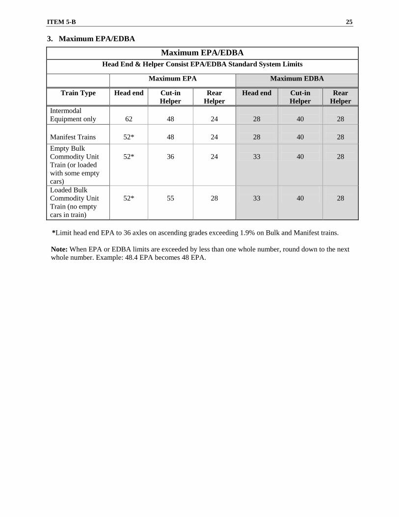
3. Maximum EPA/EDBA
Maximum EPA/EDBA Head End & Helper Consist EPA/EDBA Standard System Limits
Maximum EPA Maximum EDBA
Train Type Head end Cut-in Helper
Rear Helper
Head end Cut-in Helper
Rear Helper
Intermodal Equipment only
62
48
24
28
40
28
Manifest Trains
52*
48
24
28
40
28
Empty Bulk Commodity Unit Train (or loaded with some empty cars)
52*
36
24
33
40
28
Loaded Bulk Commodity Unit Train (no empty cars in train)
52*
55
28
33
40
28
*Limit head end EPA to 36 axles on ascending grades exceeding 1.9% on Bulk and Manifest trains. Note: When EPA or EDBA limits are exceeded by less than one whole number, round down to the next whole number. Example: 48.4 EPA becomes 48 EPA.
26 ITEM 5-B
4. Car Placement Restrictions
Note: The addition of helper(s) may not be used to provide relief from the following car placement restrictions. Any placement errors will be indicated on the 'detailed' train consist. If no errors are indicated, the detailed train consist will govern train make-up and helper placement. Additional car placement restrictions are also listed in Item 5-C. Car definitions are located at the end of Item 5-B.
Car Placement Restrictions
A. Train’s Total Trailing Tonnage Exceeds 7,000 tons
Rear 1/4 of the train must not weigh more than 1/3 of the total weight (i.e. a 100 car train weighing 9000 tons must not have more than 3000 tons in the rear 25 cars. Round up other than whole numbers; a 102 car train weighing 9002 tons must not have more than 3001 tons in the rear 26 cars).
Exception: This does not apply to:
• Trains made up entirely of cars weighing a minimum of 45 tons each.
• Solid loaded or solid empty unit bulk commodity trains.
• Trains made up entirely of intermodal equipment. B. Train’s Total Trailing Tonnage Exceeds 5,500 tons but not more than 12,000 tons
Place cars listed below no closer than the 11th car/platform/unit/well behind the lead consist:
• Car that is 80 feet or longer and weighs less than 45 tons.
• Multi-platform/unit/well cars having one or more empty platforms, units or wells.
• Autoracks weighing less than 60 tons, except when train consists entirely of autoracks.
C. Train’s Total Trailing Tonnage Exceeds 12,000 tons
Place cars listed below no closer than the 16th car/platform/unit/well behind the lead consist: • Conventional car weighing less than 45 tons.
• Car that is 80 feet or longer and weighs less than 45 tons. Multi-platform/unit/well cars having one or more empty platforms, units, or wells.
• Intermodal flatcar 80 feet or longer in length loaded with a single trailer or container. This also applies to two unit, solid drawbar connected, twin flatcars (186 feet in total length) with a single trailer/container on either unit.
• Two-unit solid drawbar-connected long cars (P2) if the total weight of the car is less than 120 tons.
• Three and four-unit solid drawbar-connected multi-well cars (P3 / P4) with any well weighing less than 45 tons.
• Autoracks weighing less than 60 tons, except when train consists entirely of autoracks.
Note: A Two-Unit Articulated Autorack is considered two cars.
D. Long Car/ Short Car
Do not couple freight cars 80 feet or longer to any car 45 feet or shorter when weight behind the coupling would exceed 3000 tons. However, this does not apply to:
• A locomotive crane 45 feet or shorter when coupled to a boom idler car 80 feet or longer.
• A car listed in the train consist as 80 feet and the consist does not show a train placement error.
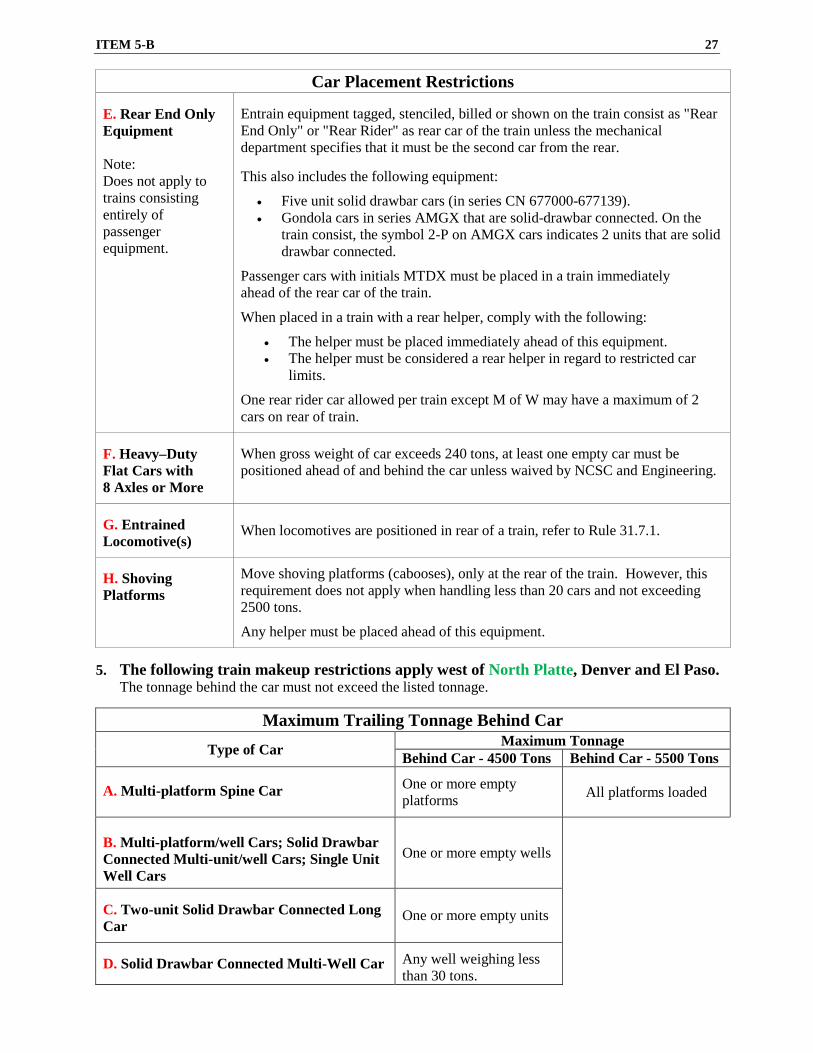
ITEM 5-B 27
Car Placement Restrictions E. Rear End Only Equipment Note: Does not apply to trains consisting entirely of passenger equipment.
Entrain equipment tagged, stenciled, billed or shown on the train consist as "Rear End Only" or "Rear Rider" as rear car of the train unless the mechanical department specifies that it must be the second car from the rear. This also includes the following equipment:
• Five unit solid drawbar cars (in series CN 677000-677139). • Gondola cars in series AMGX that are solid-drawbar connected. On the
train consist, the symbol 2-P on AMGX cars indicates 2 units that are solid drawbar connected.
Passenger cars with initials MTDX must be placed in a train immediately ahead of the rear car of the train.
When placed in a train with a rear helper, comply with the following:
• The helper must be placed immediately ahead of this equipment. • The helper must be considered a rear helper in regard to restricted car
limits.
One rear rider car allowed per train except M of W may have a maximum of 2 cars on rear of train.
F. Heavy–Duty Flat Cars with 8 Axles or More
When gross weight of car exceeds 240 tons, at least one empty car must be positioned ahead of and behind the car unless waived by NCSC and Engineering.
G. Entrained Locomotive(s)
When locomotives are positioned in rear of a train, refer to Rule 31.7.1.
H. Shoving Platforms
Move shoving platforms (cabooses), only at the rear of the train. However, this requirement does not apply when handling less than 20 cars and not exceeding 2500 tons.
Any helper must be placed ahead of this equipment.
5. The following train makeup restrictions apply west of North Platte, Denver and El Paso.
The tonnage behind the car must not exceed the listed tonnage.
Maximum Trailing Tonnage Behind Car
Type of Car Maximum Tonnage
Behind Car - 4500 Tons Behind Car - 5500 Tons A. Multi-platform Spine Car
One or more empty platforms All platforms loaded
B. Multi-platform/well Cars; Solid Drawbar Connected Multi-unit/well Cars; Single Unit Well Cars
One or more empty wells
C. Two-unit Solid Drawbar Connected Long Car
One or more empty units
D. Solid Drawbar Connected Multi-Well Car
Any well weighing less than 30 tons.
28 ITEM 5-B
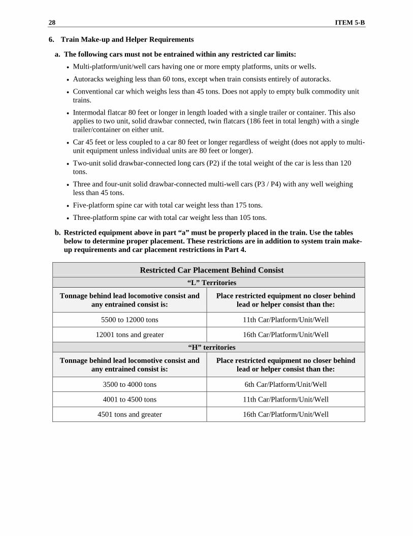
6. Train Make-up and Helper Requirements a. The following cars must not be entrained within any restricted car limits:
• Multi-platform/unit/well cars having one or more empty platforms, units or wells.
• Autoracks weighing less than 60 tons, except when train consists entirely of autoracks.
• Conventional car which weighs less than 45 tons. Does not apply to empty bulk commodity unit trains.
• Intermodal flatcar 80 feet or longer in length loaded with a single trailer or container. This also applies to two unit, solid drawbar connected, twin flatcars (186 feet in total length) with a single trailer/container on either unit.
• Car 45 feet or less coupled to a car 80 feet or longer regardless of weight (does not apply to multi- unit equipment unless individual units are 80 feet or longer).
• Two-unit solid drawbar-connected long cars (P2) if the total weight of the car is less than 120 tons.
• Three and four-unit solid drawbar-connected multi-well cars (P3 / P4) with any well weighing less than 45 tons.
• Five-platform spine car with total car weight less than 175 tons.
• Three-platform spine car with total car weight less than 105 tons. b. Restricted equipment above in part “a” must be properly placed in the train. Use the tables
below to determine proper placement. These restrictions are in addition to system train make-up requirements and car placement restrictions in Part 4.
Restricted Car Placement Behind Consist
“L” Territories
Tonnage behind lead locomotive consist and any entrained consist is:
Place restricted equipment no closer behind lead or helper consist than the:
5500 to 12000 tons 11th Car/Platform/Unit/Well
12001 tons and greater 16th Car/Platform/Unit/Well
“H” territories
Tonnage behind lead locomotive consist and any entrained consist is:
Place restricted equipment no closer behind lead or helper consist than the:
3500 to 4000 tons 6th Car/Platform/Unit/Well
4001 to 4500 tons 11th Car/Platform/Unit/Well
4501 tons and greater 16th Car/Platform/Unit/Well
ITEM 5-B 29
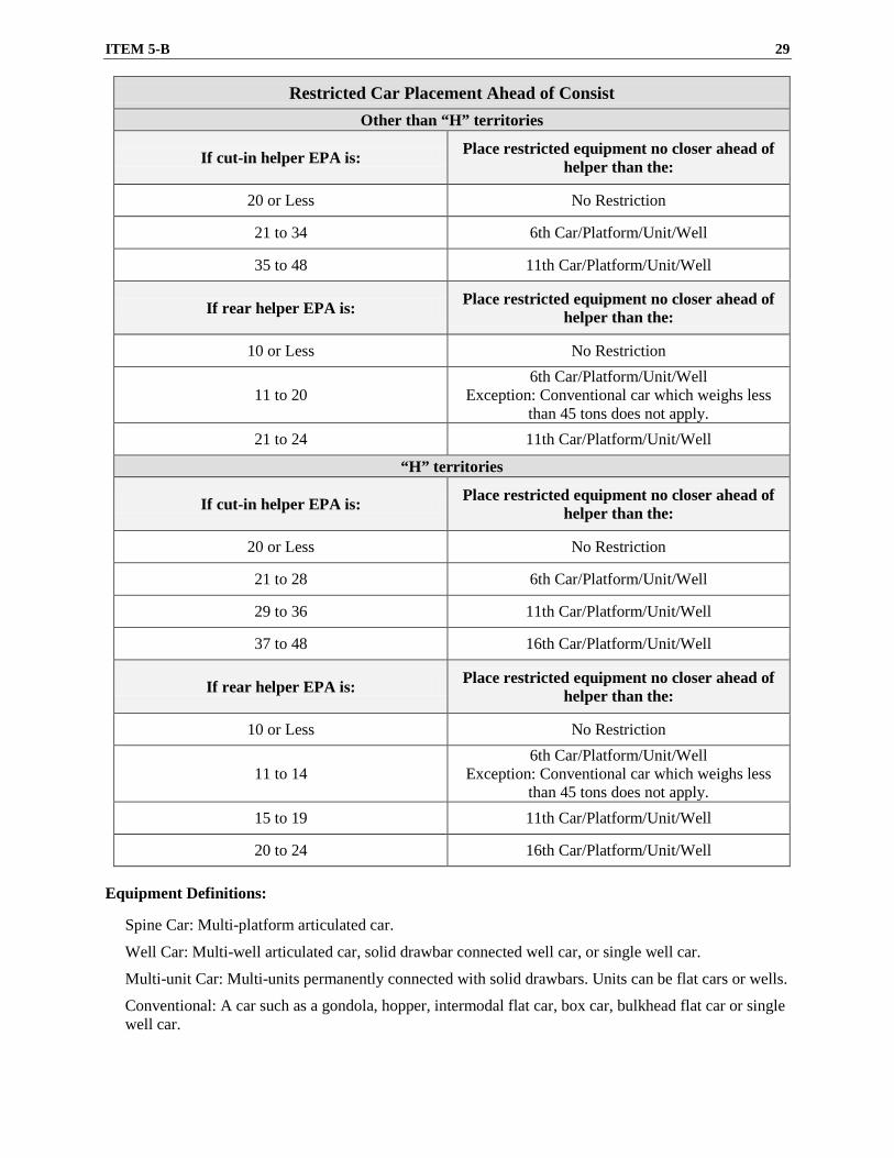
Restricted Car Placement Ahead of Consist Other than “H” territories
If cut-in helper EPA is: Place restricted equipment no closer ahead of helper than the:
20 or Less No Restriction
21 to 34 6th Car/Platform/Unit/Well
35 to 48 11th Car/Platform/Unit/Well
If rear helper EPA is: Place restricted equipment no closer ahead of helper than the:
10 or Less No Restriction
11 to 20 6th Car/Platform/Unit/Well
Exception: Conventional car which weighs less than 45 tons does not apply.
21 to 24 11th Car/Platform/Unit/Well
“H” territories
If cut-in helper EPA is: Place restricted equipment no closer ahead of helper than the:
20 or Less No Restriction
21 to 28 6th Car/Platform/Unit/Well
29 to 36 11th Car/Platform/Unit/Well
37 to 48 16th Car/Platform/Unit/Well
If rear helper EPA is: Place restricted equipment no closer ahead of helper than the:
10 or Less No Restriction
11 to 14 6th Car/Platform/Unit/Well
Exception: Conventional car which weighs less than 45 tons does not apply.
15 to 19 11th Car/Platform/Unit/Well
20 to 24 16th Car/Platform/Unit/Well
Equipment Definitions:
Spine Car: Multi-platform articulated car.
Well Car: Multi-well articulated car, solid drawbar connected well car, or single well car.
Multi-unit Car: Multi-units permanently connected with solid drawbars. Units can be flat cars or wells.
Conventional: A car such as a gondola, hopper, intermodal flat car, box car, bulkhead flat car or single well car.
30 ITEM 5-C
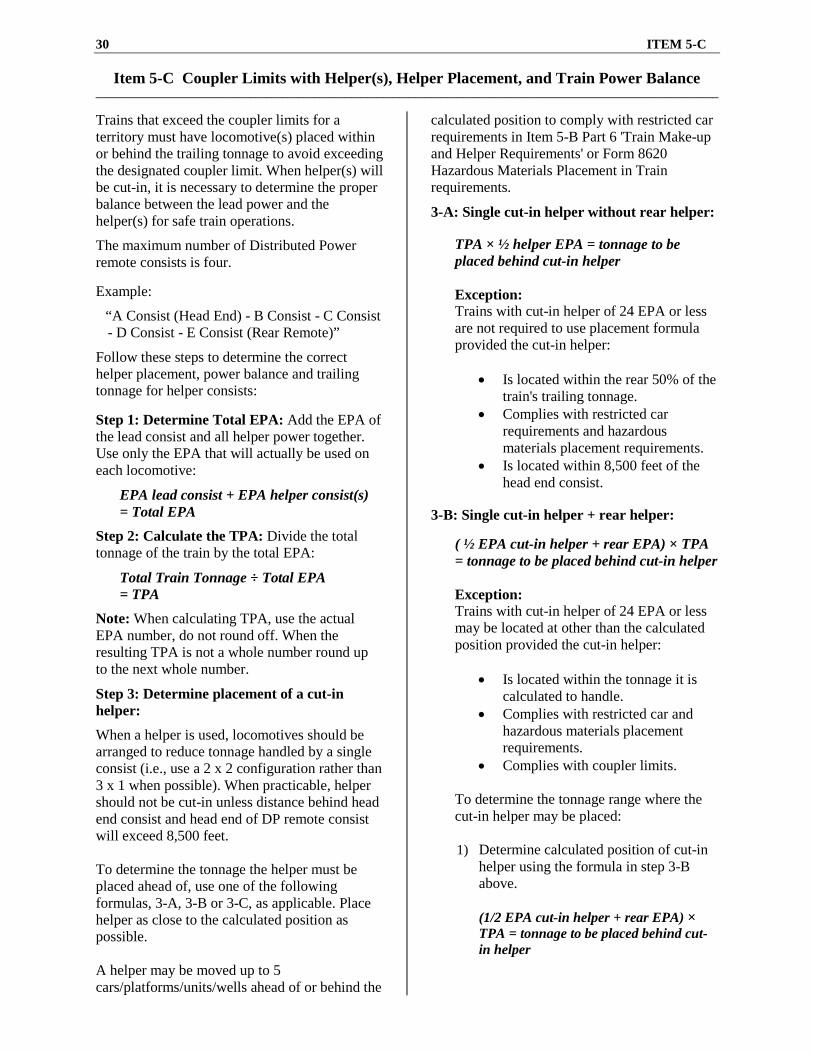
Item 5-C Coupler Limits with Helper(s), Helper Placement, and Train Power Balance _____________________________________________________________________________________________________________________ Trains that exceed the coupler limits for a territory must have locomotive(s) placed within or behind the trailing tonnage to avoid exceeding the designated coupler limit. When helper(s) will be cut-in, it is necessary to determine the proper balance between the lead power and the helper(s) for safe train operations.
The maximum number of Distributed Power remote consists is four. Example:
“A Consist (Head End) - B Consist - C Consist - D Consist - E Consist (Rear Remote)”
Follow these steps to determine the correct helper placement, power balance and trailing tonnage for helper consists:
Step 1: Determine Total EPA: Add the EPA of the lead consist and all helper power together. Use only the EPA that will actually be used on each locomotive:
EPA lead consist + EPA helper consist(s) = Total EPA
Step 2: Calculate the TPA: Divide the total tonnage of the train by the total EPA:
Total Train Tonnage ÷ Total EPA = TPA
Note: When calculating TPA, use the actual EPA number, do not round off. When the resulting TPA is not a whole number round up to the next whole number.
Step 3: Determine placement of a cut-in helper:
When a helper is used, locomotives should be arranged to reduce tonnage handled by a single consist (i.e., use a 2 x 2 configuration rather than 3 x 1 when possible). When practicable, helper should not be cut-in unless distance behind head end consist and head end of DP remote consist will exceed 8,500 feet. To determine the tonnage the helper must be placed ahead of, use one of the following formulas, 3-A, 3-B or 3-C, as applicable. Place helper as close to the calculated position as possible. A helper may be moved up to 5 cars/platforms/units/wells ahead of or behind the
calculated position to comply with restricted car requirements in Item 5-B Part 6 'Train Make-up and Helper Requirements' or Form 8620 Hazardous Materials Placement in Train requirements.
3-A: Single cut-in helper without rear helper:
TPA × ½ helper EPA = tonnage to be placed behind cut-in helper Exception: Trains with cut-in helper of 24 EPA or less are not required to use placement formula provided the cut-in helper:
• Is located within the rear 50% of the train's trailing tonnage.
• Complies with restricted car requirements and hazardous materials placement requirements.
• Is located within 8,500 feet of the head end consist.
3-B: Single cut-in helper + rear helper:
( ½ EPA cut-in helper + rear EPA) × TPA = tonnage to be placed behind cut-in helper Exception: Trains with cut-in helper of 24 EPA or less may be located at other than the calculated position provided the cut-in helper:
• Is located within the tonnage it is calculated to handle.
• Complies with restricted car and hazardous materials placement requirements.
• Complies with coupler limits. To determine the tonnage range where the cut-in helper may be placed: 1) Determine calculated position of cut-in
helper using the formula in step 3-B above. (1/2 EPA cut-in helper + rear EPA) × TPA = tonnage to be placed behind cut-in helper
ITEM 5-C 31
2) Determine tons cut-in helper may be moved ahead of or behind the calculated position:
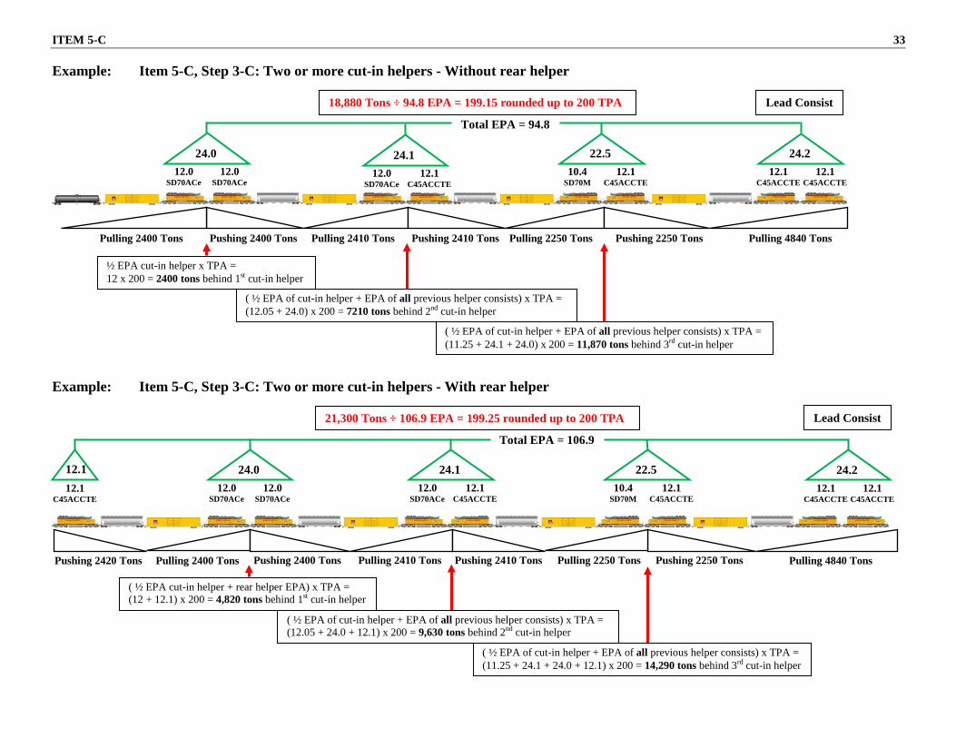
½ EPA cut-in helper x TPA = Tons cut-in helper may be moved from calculated position
Example: 18,000 ton train is operating with lead consist of 36 EPA, single cut-in helper with 24 EPA and a rear helper with 24 EPA (total EPA of train is 84 EPA). The TPA is 215 and, using the formula in step 3-B, the calculated position of the cut-in helper is ahead of 7,740 tons. ½ EPA of the cut-in helper is 12. 12 x 215 = 2,580 tons Cut-in helper may be moved 2,580 tons ahead of or behind the calculated position.
3-C: Two or more cut-in helpers:
• Without rear helper:
Start at the rear of the train and multiply the TPA by ½ the EPA of the first cut-in helper.
TPA × ½ helper EPA of first cut-in helper = tonnage to be placed behind first cut-in helper
• With rear helper:
Start at the rear of the train and add ½ the EPA of the first cut-in helper to EPA of the rear helper. Multiply this figure by the TPA.
( ½ EPA of first cut-in helper + rear helper EPA) × TPA = tonnage to be placed behind first cut-in helper
For each additional cut-in helper the following applies. Add ½ the EPA of the next helper to the total EPA of all previous helper consists. Multiply this figure by the TPA.
( ½ EPA of next helper to be cut-in + EPA of all previous helper consists) × TPA = tonnage to be placed behind the helper consist being cut-in
Step 4: Determine that trailing tonnage handled by each consist is less than the coupler limits, by using the formulas below.
• Tonnage pulled by Lead Consist: Multiply the EPA of lead consist by the TPA. This figure must be less than the coupler limit for the territory. Applies to trains with cut-in helper(s), (with or without rear helper), and trains with rear only helper.
EPA of lead consist x TPA = tonnage pulled by lead consist (Must be less than coupler limit)
• Tonnage pulled behind cut-in helper:
Multiply ½ the EPA of the helper by the TPA. This number must be less than the coupler limit for the territory.
½ EPA of helper × TPA = tonnage pulled by helper consist (Must be less than coupler limit)
See following page for examples of trains with two or more cut-in helpers.
32 ITEM 5-C
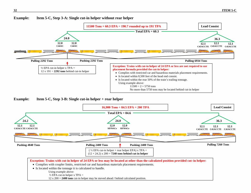
Example: Item 5-C, Step 3-A: Single cut-in helper without rear helper
( ½ EPA cut-in helper + rear helper EPA) x TPA = (12 + 24.2) x 200 = 7240 tons behind cut-in helper
11500 Tons ÷ 60.3 EPA = 190.7 rounded up to 191 TPA Lead Consist Total EPA = 60.3
24.0 12.0
C44AC 12.0
C44AC
36.3 12.1
C45ACCTE 12.1
C45ACCTE 12.1
C45ACCTE
16,900 Tons ÷ 84.5 EPA = 200 TPA
Total EPA = 84.6
Lead Consist
24.0 12.0
SD70ACe 12.0
SD70ACe
24.2 12.1
C45ACCTE 12.1
C45ACCTE
36.3
12.1 C45ACCTE
12.1 C45ACCTE
12.1 C45ACCTE
Pulling 2400 Tons Pushing 2400 Tons
Exception: Trains with cut-in helper of 24 EPA or less may be located at other than the calculated position provided cut–in helper: • Complies with coupler limits, restricted car and hazardous materials placement requirements. • Is located within the tonnage it is calculated to handle.
Using example above: ½ EPA cut-in helper x TPA = 12 x 200 = 2400 tons cut-in helper may be moved ahead / behind calculated position.
½ EPA cut-in helper x TPA = 12 x 191 = 2292 tons behind cut-in helper
Exception: Trains with cut-in helper of 24 EPA or less are not required to use placement formula provided the cut-in helper: • Complies with restricted car and hazardous materials placement requirements. • Is located within 8,500 feet of the head end consist. • Is located within the rear 50% of the train’s trailing tonnage.
Using example above: 11500 ÷ 2 = 5750 tons No more than 5750 tons may be located behind cut-in helper
ITEM 5-C 33
Example: Item 5-C, Step 3-C: Two or more cut-in helpers - Without rear helper
Example: Item 5-C, Step 3-C: Two or more cut-in helpers - With rear helper
21,300 Tons ÷ 106.9 EPA = 199.25 rounded up to 200 TPA
Total EPA = 106.9
24.1 12.1
C45ACCTE 12.0
SD70ACe
22.5 12.1
C45ACCTE 10.4
SD70M
24.2 12.1
C45ACCTE 12.1
C45ACCTE
24.0 12.0
SD70ACe 12.0
SD70ACe 12.1
C45ACCTE
12.1
Lead Consist
( ½ EPA of cut-in helper + EPA of all previous helper consists) x TPA = (12.05 + 24.0 + 12.1) x 200 = 9,630 tons behind 2nd cut-in helper ( ½ EPA of cut-in helper + EPA of all previous helper consists) x TPA =
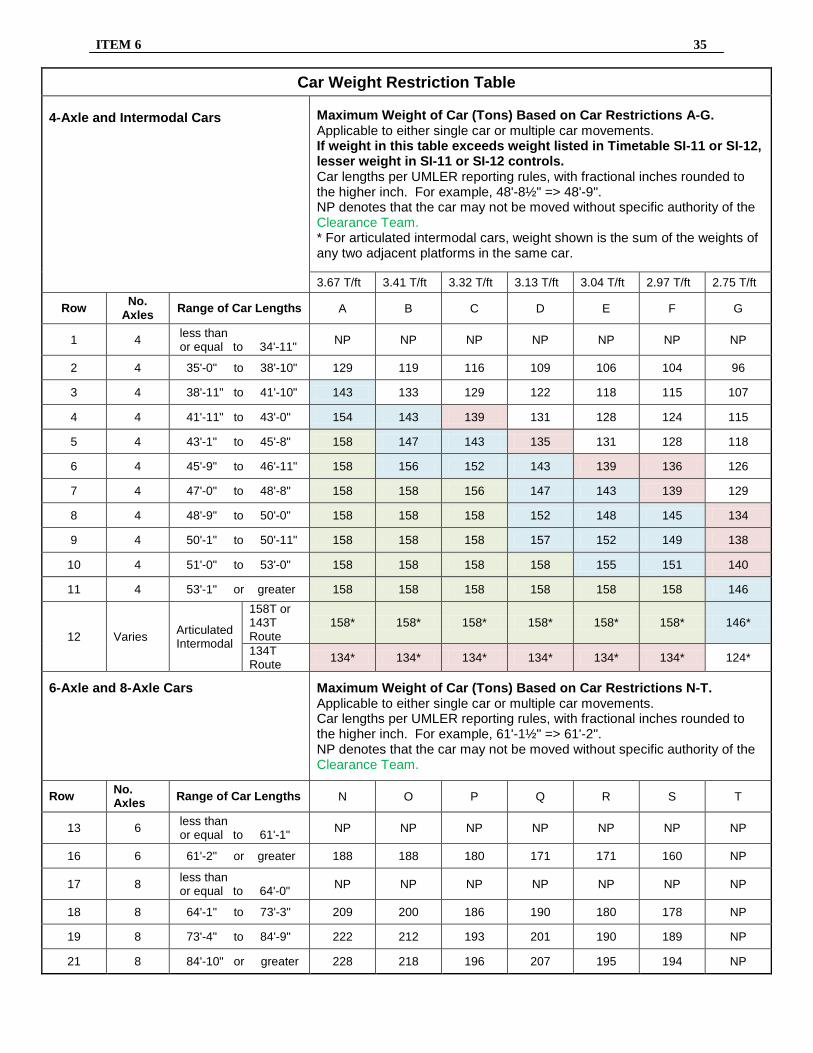
Item 6 Maximum Gross Weight Limitations ________________________________________________________________________________________________________ Maximum gross weight restrictions are shown in Timetable Item SI-12 for Subdivisions or SI-11 for Industrial Leads. They will indicate a maximum gross weight for a four-axle car with a coupled length of 53 feet 1 inch or longer and two letter restrictions (A through G and N through T). Maximum gross weight for cars shorter than 53 feet 1 inch, articulated intermodal cars, six-axle cars, or eight-axle cars can be obtained from the Car Weight Restriction Table by referencing the car length, axle count, and letter restriction. The gross weight of a four-axle car may not exceed the most restrictive case of either:
• maximum gross weight based on journal size or other mechanical considerations, or
• maximum gross weight for subdivision (SI-12) or industrial lead (SI-11), or
• maximum gross weight for car length and letter restriction from the Car Weight Restriction Table.
Examples: SI-12 for Subdivision XXX states “143 Tons, Restrictions C and R.” a. For a four axle car 53’-1” long, the table
indicates 158 Tons (row 11, column C). However, the car weight is restricted to 143 Tons by SI-12 maximum gross weight.
b. For a four axle car 41’-11” long, the table indicates 139 Tons (row 4, column C). The car weight is restricted to 139 Tons.
c. For an eight-axle car 74’-10” long, the table indicates 190 Tons (row 19, column R). The car weight is restricted to 190 Tons.
1.
Cars Exceeding Authorized Weights Cars that do not meet the specified weight limits and cars having more than eight axles are not permitted without specific authority of the Clearance Team (800-544-0541) in the National Customer Service Center.
2. Six-Axle Locomotives Do not operate six-axle locomotives on subdivisions or industrial leads where the maximum gross weight limitation is less than 120 Tons.
3. Cranes and Pile Drivers Do not operate relief outfit cranes, locomotive cranes, cranes, or pile drivers on subdivisions or industrial leads where the maximum gross weight limitation is less than 132 Tons.
4. Multiplatform Cars Multiplatform cars are identified on the train consist as either “articulated” or “solid drawbar connected.” Weights and lengths are given for each individual platform.
To determine maximum allowable gross weight: • For a solid drawbar connected car, treat
each platform as a separate car and refer to the SI-11 or SI-12 restriction and the Car Weight Restriction Table.
• For an articulated car, refer to row 12 of the Car Weight Restriction Table. The maximum weight shown applies to the sum of the weights of any two adjacent platforms in the same car.
5. Modifications
Changes to maximum gross weight restrictions in Timetable Items SI-11 and SI-12 must be submitted to the Manager Operating Rules and approved by the Director Structures Design.
ITEM 6 35
Car Weight Restriction Table
4-Axle and Intermodal Cars
Maximum Weight of Car (Tons) Based on Car Restrictions A-G. Applicable to either single car or multiple car movements. If weight in this table exceeds weight listed in Timetable SI-11 or SI-12, lesser weight in SI-11 or SI-12 controls. Car lengths per UMLER reporting rules, with fractional inches rounded to the higher inch. For example, 48'-8½" => 48'-9". NP denotes that the car may not be moved without specific authority of the Clearance Team. * For articulated intermodal cars, weight shown is the sum of the weights of any two adjacent platforms in the same car.
Maximum Weight of Car (Tons) Based on Car Restrictions N-T. Applicable to either single car or multiple car movements. Car lengths per UMLER reporting rules, with fractional inches rounded to the higher inch. For example, 61'-1½" => 61'-2". NP denotes that the car may not be moved without specific authority of the Clearance Team.
Row No. Axles Range of Car Lengths N O P Q R S T
13 6 less than or equal to 61'-1" NP NP NP NP NP NP NP
16 6 61'-2" or greater 188 188 180 171 171 160 NP
17 8 less than or equal to 64'-0" NP NP NP NP NP NP NP
Employees must provide themselves with their own copy of the following and have them available for reference:
• This UPRR System Special Instructions
document, which supersedes all previous System Special Instructions.
• Current applicable area timetable(s) for territories upon which operating.
− Chicago Area Timetable #5, effective 0900C
on 10/13/2014. − Council Bluffs Area Timetable #5, effective
0900C on 11/14/2016. − Dallas/Ft. Worth Area Timetable #5,
effective 0900C on 09/28/2015. − Denver Area Timetable #5, effective 0900C
on 09/28/2015. − Houston Area Timetable #6, effective
0900C on 01/26/2015. − Iowa Area Timetable #5, effective 0900C on
11/14/2016. − Kansas City Area Timetable #4, effective
0900C on 2/28/2011. − Livonia Area Timetable #1, effective 0900C
on 01/26/2015. − Los Angeles Area Timetable #5, effective
0900C on 10/28/2013. − North Little Rock Area Timetable #6,
effective 0900C on 11/14/2016. − North Platte Area Timetable #4, effective
0900C on 03/19/2012. − Portland Area Timetable #6, effective
0900C on 10/13/2014. − Roseville Area Timetable #6, effective
0900C on 10/22/2012. − Salina Area Timetable #5, effective 0900C
on 12/16/2013. − Salt Lake City Area Timetable #5, effective
0900C on 12/07/2015. − San Antonio Area Timetable #5, effective
0900C on 03/25/2013. − St. Louis Area Timetable #5, effective
0900C on 05/27/2013. − Sunset Area Timetable #4, effective 0900C
on 04/14/2014. − Twin Cities Area Timetable #5, effective
0900C on 11/14/2016.
• Subdivision general order for each subdivision operating on. There is one general order in effect for each subdivision.
• Current system general orders.
Note: There are 10 system general orders in effect at any given time that employees are required to have. System general orders are categorized as follows:
SSI 1 - 3 (1 Time Comparison; 2 Speed Restrictions; and 3 Trains Handling - Company Equipment)
SSI 4 - 5-C (4 Locomotive Information; and 5 Car Placement and Train Make-up Restrictions)
SSI 6 - 9 (6 Maximum Gross Weight Limitations; 7 Employee Information; 8 Heavy and Mountain Grade Operations; and 9 Use of Engine Horns)
SSI 10 - 10-B (10-A General Code of Operating Rules; and 10-B (Reserved))
SSI 10-C - 10-D (10-C Air Brake & Train Handling Rules; and 10-D Maintenance of Way Rules)
SSI 10-E - 10-G (10-E Safety Rules; 10-F Inspecting, Welding and Grinding of Rail and Track Components; and 10-G Chief Engineer Instruction Bulletins)
SSI 23 – 24 (23 Security Alert Instructions; and 24 California Proposition 65 Warning)
ITEM 7-A 37
• All rule books must contain the current rules and the latest revised chapters/pages in the proper page sequence. The required rule chapters for each employee work group are listed below. All employees must have a current copy of and comply with the rules corresponding to one of these work groups. If you have responsibilities that require rules in addition to those listed for your work group, contact your supervisor.
• Instructions for Handling Hazardous Materials, Form 8620, effective June 1, 2017. Required for all employees examined on the General Code of Operating Rules. Conductors who transport hazardous materials must also have a copy of the current Emergency Response Guidebook (ERG) (2016) readily accessible while on duty.
• Track Welding Rules and Procedures for
Inspecting, Welding, and Grinding of Rail and Track Components, effective 05/02/2016, required for track supervisors, section foremen, and track welders, grinders, and slotters.
• Electrical Safety Rules, effective July 1, 2010, Required for Maintenance Operations,
05/02/16, required for all examined Engineering Department employees and Transportation Department managers.
• UPRR photo identification card (National
Badge). Each National Badge expires after 6 years. If your National Badge is expired, contact your manager to get a new photo taken as soon as possible. The National Badge must be kept current whether the employee has a certification or not. A separate UP photo ID will not be required to be in their possession if the employee has a photo on their FRA certificate.
• A valid "FRA Certificate" card, if applicable,
regardless of the type of service the employee is called to perform, must be in the employee's possession while on duty. Each FRA Certificate must have your photo on it to be valid. If you are issued an FRA certificate with no photo, contact your manager to get a new photo taken as soon as possible. Within 10 days after taking your photo notify EC&L at 544-CERT. Restrictions listed on certificate must be complied with as required. Certified employees who wear contact lenses must have a pair of corrective glasses available while on duty.
Electronic Versions Access and use of approved electronic media must be restricted in accordance with Rule 2.21 Electronic Devices. Employees may utilize electronic media (Laptop, Tablet, Smartphone etc.) to access the approved electronic versions from the UP Website in lieu of printed copies. Follow these instructions to download rules or documents specified in SSI Item 7-A from the Employee website: 1. Select Departments.
2. Under Operating, select Operations Support.
3. Under Rules, select UP Rule Book.
4. Follow instructions for desired download.
38 ITEM 7-A
Employees must be able to access the electronic versions in a timely manner. This does not relieve employees from having the most current required revisions. Electronic versions must be capable of displaying information as intended, and Timetables and Form 8620 must be displayed in color.
When using electronic devices, the UPRR General Code version applies only when operating on UPRR trackage. UPRR crews operating on foreign lines must use the BASIC General Code of Operating Rules.
Item 7-B Qualifications of Certified Employees ________________________________________________________________________________________________________ A. Locomotive Engineers Qualification is determined by a Designated Supervisor of Locomotive Engineers (DSLE) before the locomotive engineer is allowed to operate without direct on-board supervision. Depending on individual case-by-case circumstances, a DSLE may provide notice of qualification after a ride, face-to-face discussion, telephone conversation, or electronic notification with the locomotive engineer. However, if the locomotive engineer disagrees with the decision that he or she is qualified, a DSLE must ride with the locomotive engineer before qualification. The ride must be of sufficient duration over the most demanding portion of the territory to ensure proficiency. 1. Initial Familiarization Prior to being qualified on a main track territory upon which the employee has never operated in the capacity of a locomotive engineer, he or she must make familiarization trips over the entire territory. The average number of familiarization trips necessary for qualification will be determined jointly by the Director Road Operations and DSLE responsible for that location. The average number of trips necessary is based on qualifying the typical locomotive engineer. Prior experience will be taken into account in determining the number of required trips. Certain non-mainline territories, i.e. industrial leads, have such generic and undemanding characteristics that familiarization with similar or more challenging territories may be used in-lieu of trip(s).
2. Maintaining Locomotive Engineer Proficiency
An engineer who has not worked any road trips in the past 12 months on territories in which the locomotive engineer was previously qualified must notify his/her DSLE. When CMS calls an engineer to work a road trip for skills proficiency, a DSLE or a qualified engineer familiar with the territory will accompany the engineer. To the extent practicable, the DSLE will conduct an annual monitored ride during the trip pursuant to the FRA engineer certification requirements for engineers who do not normally work road trips. 3. Route Familiarization Route familiarization is required in order to perform service as a certified locomotive engineer without the assistance of a pilot. After initial qualification on a specific route by completing the required familiarization plan specified by the DSLE, route familiarization is maintained by observing the route when performing service in any capacity (engineer or trainman) every 12 months. Other methods of maintaining route familiarization may also be specified by a DSLE. Locomotive engineers are responsible for maintaining territory familiarization on the routes in their respective seniority districts. Exception: Route familiarization as outlined above on the heavy and/or mountain grades of subdivisions listed in the following table, in any capacity, is required every 5 months.
In addition to the twelve month requirements, engineers subject to call on the following territories who have not worked both directions in the past five months must notify their manager. When notified, the manager will discuss the familiarization requirements to determine if familiarization trips are needed. An engineer who has not worked both directions during the preceding six months must notify CMS and their manager of this fact. Unless otherwise instructed by the DSLE assigned to the territory in question, the engineer is prohibited from operating a train on the territory unless accompanied by a DSLE or a qualified engineer familiar with the territory. Subdivision
Between
Subdivision
Between
Los Angeles
Yermo and W. Riverside
Montana
Monida and Waco, Apex and Silver Bow
Cima
Cima and Kelso
Greeley
Lasalle and Cheyenne
Caliente
Crestline and Las Vegas
Green River
Grand Junction and Helper
Huntington
LaGrande and Huntington
Provo
Helper and Salt Lake
LaGrande
LaGrande and Hinkle
Lakeside
Ogden and Alazon
Canyon
Portola and Oroville
Evanston
Wahsatch and Echo
Brooklyn
Eugene and Oakridge
Tennessee Pass
Minturn and Dotsero
Valley
Dunsmuir and Redding
Laramie
Sherman and Cheyenne
Cascade
Oakridge and Klamath Falls
Colorado Springs
Denver and Colorado Springs
Black Butte
Klamath Falls and Dunsmuir
Mojave
Bakersfield and West Colton
Roseville
Roseville and Sparks
Yuma
West Colton and Indio
Moffat Tunnel
Denver and Tabernash Bond and Crater
SCRRA
Palmdale and Burbank Jct.
Craig
Phippsburg and Craig
Coast
San Luis Obispo and Santa Margarita
4. Cut back engineers and engineers recalled
to engine service or hostling positions: a. Many promoted engineers retain seniority rights as brakemen and/or conductors. Due to changes in work force requirements, some of these engineers may be cut back to brakeman or conductor assignments. When this occurs, these individuals may be permitted to operate the locomotive under the provisions of Rule 1.47 B. l. if:
• Such activity does not interfere with their
assigned duties.
• They have the consent of the working engineer of the crew.
Locations are not limited to territories where the employee was previously qualified. Only an engineer holding a valid Form 20106, Union Pacific Railroad FRA Certificate, is allowed to operate a locomotive or train. Seniority restrictions placed on an employee while an engineer remain in effect. A disqualified engineer must not operate a locomotive. b. Cut back brakemen or conductors who have not worked as a locomotive engineer within the past 6 months must notify their DSLE and CMS of this fact. The DSLE may require the employee to make trips over a subdivision to maintain proficiency as an engineer.
ITEM 7-B 41
c. During the first 12 months following completion of the engineer training program, an employee who has not worked any road trips as an engineer in the past 30 days, if called to work as a road engineer, must not accept the call unless so instructed by the DSLE. The DSLE will also determine what, if any, additional familiarization trips or training may be needed following any period in cut back or furloughed status within that 12 month period.
B. Remote Control Operators (RCO)
1. Qualification
Qualification is determined by a Designated Supervisor of Remote Control Operations (DSRCO) before the RCO is allowed to operate without direct supervision. Depending on individual case-by-case circumstances, a DSRCO may provide notice of qualification after a ride, face-to-face discussion, telephone conversation, or electronic notification with the RCO. However, if RCO disagrees with the decision that he or she is qualified, a DSRCO must ride with the RCO before qualification.
2. RCO position not worked in the previous 6 months
A Remote Control Operator who has not worked as a RCO in the previous 6 months must notify a service unit manager:
• Before being placed on a board that requires the employee to work a RCO position.
• If called to work a RCO position.
Employees must also inform the manager if their skill as an RCO has been evaluated in the past 12 months. The manager will determine if the employee needs familiarization after a discussion with the employee.
3. Remote Control Operators on selected jobs
The service unit will list jobs that require additional training and familiarization. Additional air brake and train/track dynamics training may be required for these jobs. The RCO is responsible for notifying a manager when placing himself or herself on a position or when force assigned to a position listed. The lead DSRCO will determine what, if any, training and familiarization is required. Remote control operators must not exceed the limits of their qualification and must inform the
manager of limits, if requested to exceed qualification.
C. Conductors
1. Initial Certification
Train service employees hired after December 1, 2012, must pass all proficiency, knowledge, and territory familiarization training and testing required by law and the Company's Conductor Certification Program to work as a certified, fully qualified conductor. 2. Territory Familiarization on Main Track
Conductors are responsible for maintaining territory familiarization on the routes in their respective seniority districts.
Each person who is called to perform service as a certified conductor must meet the territory familiarization requirements on the pertinent segment(s) of main track where they work. Route familiarization is maintained by observing the route when performing service in any capacity (engineer or trainman). Training trip(s) may be required if territory familiarization has expired and can include the use of technology and/or job aids. Employees must pass a territorial examination covering the operating conditions of main track territory where they have never operated, and for territory not traversed for a period of twenty-four (24) months or longer prior to working over that territory. Conductors must notify CMS and their assigned manager if they do not meet these territorial familiarization requirements prior to protecting service.
Exception: A pilot is not required if a conductor is working on a section of track with an average grade of less than 1% over 3 continuous miles, and any one of the following applies:
• The maximum distance the locomotive or train will be operated does not exceed one mile.
• The maximum authorized speed for any operation on the track does not exceed 20 miles per hour.
• Operations are conducted under operating rules that require every locomotive or train to proceed at a speed that permits stopping within one-half the range of vision of the locomotive engineer.
42 ITEM 7-B
3. Territory familiarization on other than main track
If a conductor has never worked on a segment of track or has not been over that track for a period of twenty-four (24) months or longer, the conductor will be:
• Accompanied by a qualified employee who meets the territorial requirements where practicable.
• Provided an appropriate job aid. or
• Receive a detailed job briefing from an employee familiar with the territory.
D. Recertification (All Classes of Service)
Employees requiring recertification packets are to print the necessary forms from the Certification area of the TE&Y portal. Instructions on printing the documents for TE&Y employees are issued in service unit superintendent’s bulletin. 150 days prior to the certification expiration date an item will be available on the “Certification” link of the TE&Y portal allowing the packet to be printed using a local printer. The packet will only be available for employees who are certified and must complete required documents for recertification. Employees are required to follow the instructions contained in the packet and complete all required forms as well as follow the instructions for obtaining hearing and/or vision exams. All required items must be completed promptly, but not less than 60 days in advance of the certificate expiration date. All certified (licensed) employees must be re-certified (licensed) every three years. FRA Certificates will expire on the employee's birthday, every third year, after initial certification. If the re-certification information is not available on the TE&Y portal, contact the licensing group at 402-544-2378. Note: If you are unable to print the necessary forms, please consult your immediate supervisor for assistance. A separate UP photo ID will not be required if the employee has a photo on their FRA certificate. All certified employees must maintain a valid, unexpired certificate. Failure to do so may result
in an interruption in service. It is the individual employee's responsibility to ensure that certification does not expire.
It is the individual employee's responsibility to ensure availability to perform service by maintaining valid certification(s). Employees must carry an unexpired FRA Certificate for freight and/or passenger service while on duty.
Employees who are certified for multiple TE&Y classes of service will be issued one certificate listing each class of service the employee is qualified to perform. In order to maintain multiple classes of service, employees will be required to satisfy all proficiency testing and regulatory recertification requirements on a periodic basis (i.e., hearing, vision, motor vehicle, certification ride, etc.). Multiple certificates will all have the same expiration date.
Recertification is required within three years of the expiration date listed on the employee’s FRA Certificate. Employees will have access to recertification instructions via the certification link in TE&Y portal 150 days prior to the expiration date on his/her license. If the re-certification item is not available on the TE&Y portal, contact the licensing group at 402-544-2378. All requirements must be completed promptly, but no less than 60 days prior to the expiration of the certification.
E. Familiarization and Pilot Authorization
All certified TE&Y employees who bid, place, or are forced to a new assignment must contact a manager to arrange for completion of any necessary company or regulatory familiarization requirements prior to working the new assignment if:
1. They have never worked the territory or
2. Their territory familiarization or territory exam for that assignment has expired.
The TE&Y employee must contact a service unit manager to authorize the use of a qualified pilot in advance of call or reporting for the assignment. Failure to comply with these instructions may subject the employee to discipline.
ITEM 8 43
Item 8 Heavy and Mountain Grade Operations ________________________________________________________________________________________________________ 1. Descending Grade Requirements
Cresting the Summit "CG"
When freight trains (leading locomotive) and light locomotive consists crest the summit of grades listed below as "CG"; speed must be at least 5 MPH below the maximum authorized speed.
Descending Grades
When operating freight trains or light locomotive consists on descending grades between locations listed below as 1% or 2%, if speed reaches 5 MPH above maximum authorized speed:
• Stop movement immediately, using an emergency brake application.
• When operating light locomotives consists, actuate and fully apply independent brake.
• After stopping, apply hand brakes as required to prevent movement.
• Do not move the train until authorized by a Designated Supervisor of Locomotive Engineers.
Refer to Rule 34.2.10 Emergency Brake Applications.
2. Two-Way EOT Requirements
The following restrictions are applicable to those grades listed below:
1% Trains departing from a designated crew change location for that train, if entering territory listed in the following table, must be equipped with an operable 2-way end-of-train telemetry device (rear-end unit and head-end unit) or equivalent device. However, the following trains do not require a 2-way EOT or equivalent device to operate on these grades:
• Passenger trains. • Local trains not exceeding 4000 trailing
tons, operating within a single designated crew district, and not operating over a section of track indicated as 2%.
• Work trains not exceeding 4000 trailing tons and not operating over a section of track indicated as 2%.
Refer to Rule 32.9.1 for further information.
2% Trains operating on the following grades listed below must be equipped with an operable 2-way end-of-train telemetry device (rear-end unit and head-end unit) or equivalent device. However, passenger trains do not require a 2-way EOT or equivalent device. Refer to Rule 32.9 End of Train Telemetry System for further information.
Note: For 1% and 2% grades also refer to Rule 32.9.1.
Subdivision/Industrial Lead Location
(Applies for movements in both directions between/at the points unless specified otherwise.)
Applicability Code
Altoona St. Paul and Hammond 1% Bend BNSF MP 102.5 CG Bingham Robbe and Midvale 2% Bingham Ind. Lead Leadmine and Welby CG Black Butte Azalea, MP 331.5, Southward
Grass Lake, MP 367.7, Southward Azalea and Dunsmuir Klamath Falls and Azalea
CG CG 2% 1%
Caliente Crestline and Las Vegas 1% Canyon Portola and Oroville 1% Carrizozo Vaughn and Alamagordo 1% Cascade Cascade Summit, MP 537.5, Northward
Cascade Summit and Oakridge CG 1%
Cedar City Cedar City, Eastward CG Chevron Industrial Lead MP 8.00 and Chevron 1% Cima Cima, MP 253.8, Westward
Cima and Kelso Las Vegas and Arden
CG 2% 1%
Clifton Clifton and Guthrie 2%
44 ITEM 8
Subdivision/Industrial Lead Location
(Applies for movements in both directions between/at the points unless specified otherwise.)
Applicability Code
Coast Cuesta, MP 235.7, Westward MP 236.6, Eastward San Luis Obispo and Santa Margarita San Luis Obispo and King City
CG CG 2% 1%
Colorado Springs Palmer Lake, MP 50.0, Southward Sedalia and Colorado Springs
CG 1%
Comstock Iron Mountain, MP 13.0, Eastward Iron Mountain and Iron Springs
CG 2%
Condon MP 8.00, Northward CG Cumberland Ind. Lead MP 9.4, Northward CG De Soto Piedmont and De Soto 1% Dry Valley MP 25.0, Southward CG Elkol Industrial Lead MP 2.4, Northward CG Evanston Wahsatch, MP 928.0, Westward, Track 1
Wahsatch and Ogden CG 1%
Falls City Atchison and Nebraska City 1% Gay Gay, MP 14.5, Westward
Gay and Nine Mile CG 1%
Glenwood Springs Bond and Grand Jct. 1% Gila Estrella and Bosque 1% Greeley Cheyenne and Greeley 1% Green River Grand Jct. And Helper 1% Huntington Encina, MP 352.0, Both directions
Telocaset, MP 312.5, Westward Pleasant Valley and Pritchard Creek Pleasant Valley and Durkee
CG CG 2% 1%
La Grande Kamela, MP 271.3, Both directions Kamela and Hilgard Kamela and Huron Minthorn and Hilgard
CG 2% 2% 1%
Lakeside MP 645.40, Eastward MP 616.3, Westward Lucian and Wells
CG CG 1%
Laramie Bufford, CP W536, Eastward, Tracks 1 & 2 Hermosa, CP W547, Westward, Track 3 Sherman and Wycon Hermosa and Red Buttes
CG CG 1% 1%
Limon Sharon Springs and Mesa 1% Livonia W. Bridge Jct. and E. Bridge Jct. 1% Lone Pine Cantil and Searles 1% Lordsburg PFE Yard and Lordsburg 1% Los Angeles Silverwood, BNSF MP 56.6, Westward
Summit and San Bernadino Riverside Jct. And Barstow
CG 2% 1%
Lufkin Appleby and Tenaha 1% Modoc Ambrose and Canby
Ambrose and Canby CG 2%
ITEM 8 45
Subdivision/Industrial Lead Location
(Applies for movements in both directions between/at the points unless specified otherwise.)
Applicability Code
Moffat Tunnel MP 50.1, Eastward MP 57.0, Westward MP 138.5, Eastward MP 154.0, Westward East Portal and Rocky Winter Park and Fraiser Crater and Bond Denver and Bond
CG CG CG CG 2% 2% 2% 1%
Mojave MP 359.5, Northward Cameron, MP 371.5, Southward Hiland, MP 463.8, Southward Through Silverwood connector track Southward, MP 464.7 Hiland and West Colton Tehachapi and Ilmon Cable Xover and Mojave Colton and Bakersfield
CG CG CG
CG 2% 2% 2% 1%
Montana Monida MP 264.0 Apex MP 340.25 Humphrey and Dubois Apex and Navy Feeley and Silver Bow Idaho Falls and Silver Bow
CG CG 2% 2% 2% 1%
Nampa Ticeska, MP 358.0, Westward Reverse, MP 391.5, Eastward Mt. Home and Bliss
CG CG 1%
Oak Creek Industrial Lead 2% Oakland Tracy and Altamont 1% Peoria Pottstown and Pioneer 1% Pocatello At Kemmerer 1% Powder River S. Morrill and E. Caballo Jct. 1% Provo MP 638.2, Eastward
MP 651.8, Westward MP 673.3, Westward Kyune and Helper Summit and Castilla Helper and Springville
CG CG CG 2% 2% 1%
Roseville MP 136.5, Westward, Track 1 MP 191.0, Westward, Tracks 1 & 2 MP 192.0, Eastward Norden and Loomis MP 114.0 Norden and Truckee Sparks and Roseville
CG CG CG 2% 2% 1%
Sanderson Maxon and Altuda 1% SCRRA Trackage Vincent 61.8
Vincent and Palmdale Vincent and Paris Burbank Jct. and Palmdale
CG 2% 2% 1%
Sedalia Dow and Smithton Rock Creek Jct. and Pleasant Hill
1% 1%
Shafter Wendover and Wells 1%
46 ITEM 8
Subdivision/Industrial Lead Location
(Applies for movements in both directions between/at the points unless specified otherwise.)
Applicability Code
Sharon Springs Brookville and Sharon Springs 1% Spokane Shiloh and Eastport 1% Stauffer Industrial Lead Stauffer and Big Island 1% Sunnyside Sunnyside and Banning 2% Tennessee Pass MP 281.8, Westward
MP 290.3, Westward Tennessee Pass and Minturn
CG CG 2%
Toyah Sweetwater and Sierra Blanca 1% Valentine Alpine and Marfa
Sierra Blanca and McNary 1% 1%
Valley Dunsmuir and Redding 1% Wallace Spokane and Eastport 1% Yoder Yoder and Egbert 1% Yuma Beaumont, MP 561.4, Westward
MP 566.2, Eastward Beaumont and Garnet Beaumont and MP 545.1
CG CG 2% 1%
ITEM 9 47
Item 9 Use of Engine Horns - Quiet Zone ________________________________________________________________________________________________________ Quiet Zone
Quiet zones are designated in the timetable. Do not sound the horn for grade crossings within limits or at locations designated on the subdivision page.
Sounded Horn
Horn may be sounded to provide a warning to animals, vehicle operators, pedestrians, trespassers or crews on other trains in an emergency situation when engineer believes such action is appropriate in order to prevent injury, death, or property damage.
Horn must be sounded when:
• Employees are working on or near the track.
• Meeting or passing the head end or rear end of a train in the vicinity of a grade crossing.
• Notified that automatic warning devices are malfunctioning or disabled or crossings require additional precautions. Sound whistle signal 5.8.2(7) regardless of any prohibition.
Critical Rules for Operating and Supply Departments
Critical Rules for All Employees Rule Number Rule Description
1.13 Reporting and Complying with Instructions 74.3 Cell Phone/Electronic Device 74.5 Seat Belts
Violations that result in property damage meeting or exceeding the FRA reportable monetary threshold.
Critical Rules - Transportation Rule Number Rule Description
1.47 Failure to Maintain Conductor's Log (Missing Entries) 2.21 Electronic Devices 5.13 Blue Signal Protection 6.5 Shoving Movements
6.5.1 Remote Control Movements (Unprotected Shove) 6.7 Remote Control Zone (Fouling an active RCL zone without permission)
6.7A Remote Control Zone – System Special Instructions (Failure to maintain a zone log when required)
6.25 Movement Against the Current of Traffic 6.27 Restricted Speed 6.28 Movement on Other Than Main Track 7.1 Switching Safely and Efficiently
8.2/8.3/8.8/8.9.1/8.20 Switches and Derails (Not resulting in FRA reportable incident) 9.5 Stop Signal 9.15 Track Permits 10.1 Authority to Enter CTC Limits
15.2 Form B Protection by Track Bulletin Form B 7.6/32.1/32.1.1/32.1.4 Securing Cars, Engines, Trains, etc.
32.1.2/32.1.3/32.2.1 Securing Cars, Engines, Trains, etc. (Failure to apply handbrakes, airbrakes, or locomotive brakes)
35.3.3/35.4.1/35.4.2/35.4.4 RCL Operations 81.2.2 Sufficient Distance 81.4.2 Getting On and Off Moving Equipment
81.5.4 Understanding Between Crew Members Before Crossing Through or Fouling Equipment
81.8.1 Avoiding Fouling Hazards 81.13.1 Working Between Equipment 81.13.2 Coupler Adjustment (Use of feet to adjust coupler)
SSI Item 8 Heavy and Mountain Grade Operations SSI Item 10K/8.3 Switch Left Open in Non-Signaled Territory
ITEM 10 49
Critical Rules continued …..
Critical Rules - Maintenance of Way / Engineering Employees Rule Number Rule Description
32.1.4 Operating and Air Brake Instructions (Applies to any MofW or work equipment handling rail cars)
42.2.2 Other Speed Requirements 42.3 Main Track Authorization 42.6 Grade Crossings
74.6.1 Back-Up Moves by Engineering Employees and Contractors 78.8 Operating Booms Near Power Lines
122.4.1.1 Wearing Fall Protection 122.4.1.2 Using Fall Protection 122.4.1.6 Working Over or Adjacent to Water 122.4.1.7 Working on Bridges over RR and Roadways 135.3.2 Lockout/Tag out Procedures 135.4 Maintenance or Repair of Running Equipment 136.3 Job Briefing
136.3.1 Job Briefing for Roadway Work Groups 136.4 On Track Safety Procedures
136.4.1 Exclusive Track Occupancy 136.4.2 Inaccessible Track 136.4.3 Individual Train Detection 136.4.4 Train Approach Warning 136.4.6 Flag Protection 136.4.7 Train Coordination 136.4.8 Automatic or Symbol (Z) Manual Interlockings 136.4.9 Train Approach Warning System (TAWS) 136.7.3 Work Zone around Machines 136.7.4 Safe Working Distance Between Machines 136.7.5 Safe Traveling Distance 136.7.6 Tying up Machines 137.2.3 Disabling Crossing Warning Device 138.3.2 Critical Lift
Critical Rules – Maintenance of Way/Engineering Employees - Track Maintenance Field Manual
Rule Number Rule Description 8.2 Standards and Compliance
4.18.6 Remedial Action Required (Rail Defects) 7.8.1 General Requirements 7.8.16 Summary of Speed Restrictions for Track Work
Critical Rules - Maintenance of Way/Engineering Employees - Engineering Fire Prevention Plan
Rule Number Rule Description 2.0 Job Briefings 4.1 Not Conducting/Documenting a Fire Risk Assessment Prior to Hot
Work Being Conducted 5.1.2/5.2.2/5.3.3/5.4.2/5.5.3/5.6.3/5.7 Not Complying When Fire Risk is High
50 ITEM 10
Critical Rules continued …..
Critical Rules - Maintenance of Way/Engineering Employees GCOR and MofW Rules Rule Number Rule Description
2.21 Electronic Devices 5.4.1 Temporary Restrictions 5.4.2 Display of Yellow Flag 5.4.3 Display of Yellow-Red Flag 5.4.4 Authorized Protection by Yellow or Yellow-Red Flag 5.4.5 Display of Green Flag 5.4.6 Display of Flags Within Current of Traffic 5.4.7 Display of Red Flag or Red Light 5.4.8 Flag Location
40.6/6.2.1 Train Location 40.6/6.5 Handling Cars Ahead of Engine
40.6/6.21.1 Protection Against Defects 40.15/15.2 Protection by Track Bulletin Form B 40.8/8.2 Position of Switches 43.5/7.6 Securing Cars, Engines, Trains, etc. 56.1.3 Compromising Signal Safety
Critical Rules - Premium Operations
Rule Number Rule Description 2.21 Electronic Devices 5.13 Blue Signal Protection
7.6/32.1.1/32.1.2/32.1.3/32.1.4/32.2.1
Securing Cars, Engines, Trains, etc.
74.12 Off Road and Yard Vehicles 81.23 Lockout Protection Required 83.1.6 Adjustment of Container on Chassis 83.1.9 Intermodal Equipment Maintenance Repair Lockout / Tagout Procedures 83.2.1 Speed Limits on Ramp 83.2.2 Observing Stop Signs / Stop Lines 83.3.2 Overhead Lifting 83.3.4 Staying Clear of a Suspended Load 83.3.5 Getting On and Off Intermodal Cars 83.3.8 Crossing Platforms 83.4.2 King Pin (Inspect to Ensure Locked) 83.4.3 Loading Container on Flat Car - COFC 83.4.5 Hitches 83.5.4 Securing Containers
ITEM 10 51
Critical Rules continued …..
Critical Rules - Mechanical/Car Rule Number Rule Description
1.11 Sleeping 2.21 Electronic Devices 5.13 Blue Signal Protection of Workmen 7.6 Securing Cars or Engines
8.2/8.20 Switches and Derails (Not resulting in FRA reportable incident) 74.12 Off Road and Yard Vehicles
78.2 Lockout/Tagout 80.14 Fall Protection 81.2.2 Sufficient Distance 81.4.2 Moving Equipment 81.8.1 Avoiding Fouling Hazards 81.10.2 Using Mobile Equipment 81.10.4 One Person Operations 81.15 Car Doors
Mechanical Fire Prevention Plan
Critical Rules - Mechanical / Locomotive Rule Number Rule Description
1.11 Sleeping 2.21 Electronic Devices 5.13 Blue Signal Protection of Workmen 6.5 Shoving Movements 7.6 Securing Cars or Engines
8.2/8.20 Switches and Derails (Not resulting in FRA reportable incident) 74.12 Off Road and Yard Vehicles 78.2 Lockout/Tagout 80.14 Fall Protection 81.2.2 Sufficient Distance 81.4.2 Moving Equipment 81.8.1 Avoiding Fouling Hazards 81.8.3 Impaired Clearances 81.10.2 Using Mobile Equipment 81.10.3 Using Locomotive 81.10.4 One Person Operations
Mechanical Fire Prevention Plan
Critical Rules - Supply/Telecom Rule Number Rule Description
70.6 Lifting and Moving Material 74.2 Driver Requirements
75.7 - Supply Forklifts Chapter 136 On Track Safety
52 ITEM 10-A
Item 10-A General Code of Operating Rules, Chapters 1 to 19
Item 10-A Instructions
Instructions modify rules or clarify the application of rules. In those cases where instructions add, change or delete a rule, the words "Add," "Change rule to read" or “Delete” preface the specific wording. All portions of the rule that are not referenced in this manner remain unchanged. When intended to clarify the application of or give additional instructions for a rule the word “Application” is used.
1.2.5 Reporting Change rule to read:
All cases of personal injury, while on duty or on company property, must be immediately reported to the proper manager. For injuries that result in medical evaluation and/or treatment from an outside provider, employees must complete the prescribed form.
A personal injury that occurs while off duty that will in any way affect employee performance of duties must be reported to the proper manager as soon as possible. The injured employee must also complete the prescribed form before returning to service.
All cases of occupational illnesses must be immediately reported to the proper manager and the prescribed form completed.
Because railroads are required by Federal Regulations to report injuries and occupational illnesses that meet certain medical treatment criteria, when medical treatment is received from an outside provider, employees must report to their manager medical treatment they receive that is directly related to their injury or illness, including follow-up visits. Below are some examples of the types of medical treatments and instructions employees must report to their manager, if provided, in relation to an injury or occupational illness:
• Medical treatments provided or recommended.
• Physical therapy or chiropractic treatments.
• Prescriptions and other medications issued or recommended, including dosages.
• Lost work day instructions.
• Work restriction instructions.
1.3.1 Rules, Regulations and Instructions Application:
Examinations are required to be passed biennially or more often when necessary to ensure employees are familiar with all rules, regulations and instructions.
Issued, Canceled, or Modified
When there is a conflict, subdivision special instructions take precedence over system special instructions.
1.3.2 General Orders Add a sentence to last paragraph:
Employees must each have a current copy of system general orders and subdivision general orders they can refer to while on duty.
1.3.3 Superintendent Bulletins, Instructions, and Notices
Change title and rule to read: 1.3.3 Superintendent Bulletins, Instructions, and Notices
Superintendent bulletins, instructions, notices, and other information are issued and canceled by the designated manager. Before beginning each day’s work or trip, crew members and any others whose duties require, must review those that apply to the territory they will work on.
1.5 Drugs and Alcohol Add as last paragraph: Refusals to provide a test sample or interference or delay in the testing process are also treated as prohibited conduct. This also includes leaving the scene of an accident, tampering or substituting a sample.
Application:
Also refer to the UPRR Drug and Alcohol Policy which governs all employees. Access the policy by using the link:
1.6.1 Motor Vehicle Driving Records Change rule to read:
A certified conductor, engineer, employee seeking initial certification or employees qualified to drive commercial motor vehicles must report any arrest, citation or conviction to an employee assistance representative at (800) 779-1212, within 48 hours for:
• Operating a motor vehicle while under the influence of or impaired by alcohol or a controlled substance.
• Refusal to undergo such testing when a law enforcement official seeks to find out whether a person is operating under the influence of alcohol or a controlled substance.
State sponsored diversion programs, guilty pleas, and completed state actions to cancel, revoke, suspend, or deny a driver's license are considered convictions as applied to this rule.
1.6.3 Notification of Deteriorating Vision or Hearing
Add Note to read:
Note: A certified conductor, engineer or employee seeking initial certification who has knowledge that a restriction listed on their FRA Certificate has been corrected or improved to meet the minimum acceptable requirement as outlined in federal regulations must report that fact immediately to the proper authority or the medical department (402-544-5234).
1.11.1 Napping Change Entire Rule to Read: TE&Y and Engineering employees, except those working in passenger or commuter service, are permitted to nap while on duty when it does not cause a delay to the operations or interfere with the performance of safety-related duties, the safety of the employee, coworkers, or the public under the following conditions:
• The employee has reported on duty and completed all necessary preparations for duty including a job briefing. These duties include reviewing all general orders, track warrants, track bulletins, and all other paperwork.
• The employee responsible for notifying a napping employee work is ready to proceed should allow at least 15 minutes for the napping employee to recover from
grogginess which may occur after awaking. Another job briefing must not occur during the 15 minute recovery period, but must take place prior to proceeding with work to ensure all employees are prepared to perform service after the operational delay has concluded.
• The napping employee is relieved of all duties during the napping period. Employees being transported to or from their job duties may nap when no safety sensitive duties are being performed by another employee.
Transportation Employee Requirements:
• When napping in a designated napping facility, one member of the assigned crew or work team must remain awake at all times to perform any work related duties including ensuring that all employees are ready to commence work promptly after the delay has ended. If the entire crew requests time to nap, the supervisor on duty may grant the request if doing so does not jeopardize the safety of the employees, the public, or train operations and will be responsible for ensuring the crew is ready to commence work promptly after the delay has ended.
• A job briefing must be conducted to review the conditions of the napping period and to reach agreement as to who will nap and who must remain awake. The employee's supervisor or co-worker has the right and responsibility to refuse to allow another employee to take a nap if doing so could jeopardize safety or cause undue delay to operations.
• Before napping is allowed on a locomotive: 1. The employee in charge of the
locomotive controls must: • Make at least a 10 pound brake pipe
reduction. • Place generator field switch in the
"OFF" position. • Center and remove the reverser, if
removable. 2. The employee who is to remain awake
must remain on the locomotive while others on the locomotive are napping, except when inspecting passing trains.
Engineering Employee Requirements:
• Employee must request a nap from their immediate supervisor and identify the location where the nap is to take place. The supervisor may grant the request if doing so
54 ITEM 10-A
does not jeopardize the safety of employees, the public or train operations. In no case may the employee nap foul of any track or in an area where equipment is operating.
• Before napping is allowed on maintenance of way equipment: The operator of the equipment must ensure the equipment is properly tied down, secured against movement and adequately ventilated.
• When on a road in a company vehicle, at least one employee in addition to the employee driving the vehicle must stay awake to help the driver identify potential hazards ahead.
1.12 Weapons Application:
Also refer to UPRR Policy to Address Violence & Abusive Behavior in the Work Place. Access the policy by using the link:
• Tampering with or disabling any locomotive-mounted safety device.
• Operating or failing to take appropriate action to prevent a train from being operated when the controlling locomotive of that train is equipped with a disabled safety device, except as provided in part C of this rule.
Safety devices include crew alertness devices, automatic cab signal devices, automatic train control/train stop devices, and audio, video and other recording devices concerning operations.
B. Inspection of Locomotive-Mounted Safety Devices
The engineer must make a visual inspection of accessible safety devices in the controlling locomotive cab, nose or vestibule, or in the cab control car when taking charge of a locomotive or train to ensure that:
• Nothing interferes with their intended function.
• Switches and breakers controlling the devices are in proper position.
• Seals, as appropriate, are properly applied.
• There is no apparent damage to the device.
If any exceptions are detected, immediately report them to the train dispatcher.
C. Operation of Trains with Defective or Disabled Locomotive-Mounted Safety Devices
Locomotives or cab control cars with defective or disabled safety devices must not be operated as the controlling unit unless:
• Provided for in the operating rules. or
• Authorized by the train dispatcher. 1.27 Divulging Information
Add new last sentence reading:
Employees are responsible for all activity with their assigned User ID's and are responsible for protecting the confidentiality of information accessed. Sharing passwords is prohibited. Unauthorized use of another person's User ID and password is prohibited.
1.33 Inspection of Freight Cars
Application:
1. When a defect is discovered, note the type of defect on proper tag and attach a tag on each side of the car.
2. Open top rail equipment loaded with wood chips or bark must be covered with approved netting.
3. When applicable, inspections required by Hazardous Materials Instructions must be completed.
1.37 Open Top Loads
Change (combine) third and fourth bullets as shown:
• Occupied locomotive or occupied caboose. 1.47 Duties of Crew Members
Change rule to read:
The conductor and the engineer are responsible for the safety and protection of their train and observance of the rules. They must ensure that their subordinates are familiar with their duties, determine the extent of their experience and knowledge of the rules, and instruct them, when necessary, on how to perform their work properly and safely. If any conditions are not covered by the rules, they must take precautions to provide protection.
ITEM 10-A 55
When the conductor is not present, other crew members must obey the instructions of the engineer concerning rules, safety, and protection of the train.
A. Conductor Responsibilities 1. Supervises the Operation
The conductor supervises the operation and administration of the train (if trains are combined with more than one conductor on board, the conductor with the most seniority takes charge). All persons employed on the train must obey the conductor's instructions, unless the instructions endanger the train's safety or violate the rules. If any doubts arise concerning the authority for proceeding or safety, the conductor must consult with the engineer who will be equally responsible for the safety and proper handling of the train.
2. Restrictions on Equipment
The conductor must advise the engineer and train dispatcher of any restriction placed on equipment being handled.
3. Calling Attention to Restrictions
The conductor must remind the engineer that the train is approaching an area restricted by:
• Limits of authority.
• Track warrant.
• Radio speed restriction.
or
• Track bulletin.
The conductor must inform the engineer after the train passes the last station, but at least 2 miles from the restriction.
4. Freight Conductors
Freight conductors are responsible for the freight carried by their train. They are also responsible for ensuring that the freight is delivered with any accompanying documents to its destination or terminal. Freight conductors must maintain any required records.
5. Conductor Report Form
UPRR crews operating on a foreign railroad are required to properly complete a UPRR form or a foreign railroad form as required by UPRR rules. Foreign railroad crews operating
on the UPRR are governed by that railroad’s rule concerning awareness forms.
"Conductor Report Form" (FORM 20849) must be maintained as follows (also see Item 10-K):
a. Road freight conductors including locals and switchers, but not including yard or passenger conductors, are required to complete the Conductor Report Form. However, yard conductors performing road service on the main track (transfer, relief service, etc.) will be required to complete the Conductor Report Form.
Remote control operators are not required to maintain a Conductor Report Form except when required by Item 10-K.
The report will include:
• The name of other than Clear wayside signals, speed of the train as head end passes and, as appropriate, a "Z" or "X".
• After passing an Approach or Diverging Approach signal, the next wayside signal must be entered regardless of signal indication including the speed of the train (even if the signal is Clear).
• Train defect detector results from all detectors (except "%" detectors) and mile post. "X" will identify in-cab communication of results.
• Approaching temporary speed restrictions that affect the train. (Enter speed of restriction on form.)
• Approaching the end of authority unless additional authority has been granted to continue on the main track. If the additional authority contains a Box 2 (after arrival) it must be included on the form.
• Train delays.
• Restricted Speed documentation. Every 2 miles that the train is operating at Restricted Speed, enter mile post location, time, train speed, a "Z" to indicate that the information was communicated between crew members and amount of air brake application if any, (None, Minimum, 10#, etc.).
• On the main track in non-signaled territory, the time, train’s milepost location, and speed every 5 miles and
56 ITEM 10-A
record an “X” to indicate that the information was communicated between crew members. (Comply with bullet 7 if operating at Restricted Speed).
• On subdivisions with a CG location (as listed in SSI Item 8), record the time and speed of the train as the train crests the
grade. Enter an “X” to indicate the information was communicated between crew members.
Entries will be made when head end of train is at or about the milepost location of required entry. Entries will be sequential and legible.
Examples
Location Signal Name or
TDD Announcement
Time
Comments & Other Delays
87.3 AA 0535 X - 52 MPH 89.1 A 0543 Z - 33 MPH Y091 S 0558 X - Stop – 8” delay 92.5 RP 0617 Z - 12 MPH 94.5 RS 0625 Z – 8 MPH - None
101.3 TSR 0643 Z - 30 MPH 103.3 ND 0657 X 115.0 XH 0715 Z – 15 MPH 130.0 0740 PU 8 cars 30” 135.0 EA 0840 Z
Note: 1. Abbreviations may be used. e.g. (Advance Approach = AA; Diverging Clear = DC; Diverging
Approach = DA; Approach = A; Approach Diverging = AD; Restricting = R; Restricted Proceed = RP; Stop = S; Speed Restriction (temporary) = TSR; End of Authority = EA; Crossing Restrictions (received enroute) = XG, XH, XS; Cab Red Zone = Z; In Cab Communication = X; No Defects = ND, Restricted Speed = RS.
2. Enter MP location where Cab Red Zone begins and/or in-cab communication takes place, when other entries are required. However, entry may be made with a signal entry when passing signal.
3. Enter delays.
b. The conductor's report must be completed (and signed on the last page to signify report is complete and accurate) on each trip or tour of duty. If the form is not available, record the information as required. Reports of the last 5 round trips (minimum of 5 days) must be kept in your possession while on duty, and presented to a manager upon request.
c. Do not erase information entered on the form. If an error is made, cross out the entry and write the correct entry.
d. When conductors with a valid Class 1 "Certificate to Operate Locomotives" are allowed to operate the engine, the time and location (beginning and ending) will be noted on the conductor’s report form. Entries on the form will not be required during this time period except entries required by Item 10-K.
B. Engineer Responsibilities 1. Operating the Engine
The engineer is responsible for safely and efficiently operating the engine. Crew members must obey the engineer's instructions that concern operating the engine. A student engineer or other qualified employee may operate the engine only under the direct and immediate supervision of the engineer. The engineer must closely monitor the employee's performance. The engineer must be in a position to take immediate action as necessary. Employees that operate an engine must have a current certificate in their possession.
2. Special Handling
The engineer must check with the conductor to determine if any cars or units in the train require special handling.
ITEM 10-A 57
C. All Crew Members Responsibilities 1. Crew Members in Control
Compartment
Crew members in the control compartment must communicate to each other any restrictions or other known conditions and required actions that affect the safe operation of their train, sufficiently in advance of such condition, to allow the engineer to take proper action. If proper action is not being taken, crew members must remind engineer of such condition and required action.
Crew members in the control compartment must be alert for signals. Crew members must: • Communicate clearly to each other the
name of signals affecting their train as soon as signals become visible or audible.
• Continue to observe signals and announce any change of aspect until the train passes the signal.
• Communicate clearly to each other the speed of the train as it passes a signal with an indication other than Clear.
• Immediately remind the engineer of the rule requirement if the signal is not complied with.
2. Radio Transmission
Except when switching, a crew member must transmit the engine number, direction, location and signal name (include track number in multiple main track CTC territory) when the head end of the train:
A. Passes a signal that requires:
• Being prepared to stop at the next signal.
• Being prepared to pass next signal at restricted speed. or
• Restricted speed.
B. Stops for a signal that requires stopping.
However, instructions may be issued to identify locations where this radio transmission is not required.
3. Proper Action
If engineer and/or conductor fail to comply with a signal indication or take proper action to comply with a restriction or rule, crew
members must immediately take action to ensure safety, using the emergency brake valve to stop the train, if necessary.
4. Performing Work
Before work is performed at a location, the crew must discuss how the work will be performed, which switches/derails will be used, what method will be used to pass signals, close clearances, and any other safety related concerns. When work is completed, the crew will confirm that work was completed as planned, switches and derails are in proper position and any unforeseen safety concerns are properly reported.
1.47.1 Cab Red Zone Add new rule:
During a Cab Red Zone (CRZ), an environment must be created in the locomotive control compartment that focuses exclusively on controlling the train, verbally communicating restrictions, and proper application of the rules. The conductor must be in the control compartment unless required to perform other duties (i.e. to operate switches, be at a road crossing, passenger train duties, etc.).
A Cab Red Zone exists during critical times such as:
• Operating at Restricted Speed. (Does not apply when switching.)
• Operating on a block signal indication less favorable than Advance Approach.
• Copying mandatory directives. • Approaching a Form B restriction. • Approaching a temporary speed
restriction that affects the train. • Approaching the end of the train's
authority.
The following restrictions or conditions are required during a Cab Red Zone:
• Cab communication is restricted to immediate responsibilities for safe train operation.
• Radio communication with the dispatcher or other employees must be limited to the train's immediate movement or conditions that affect the safety of trains.
• A crew member other than the employee operating the controls will be required to handle radio communications when that crew member is in the control compartment.
58 ITEM 10-A
Exception: Rule 33.6.1 (Operating Responsibilities with Manned Helper.)
• If proper action is not being taken, crew members must remind each other of the Cab Red Zone and/or take appropriate action to stop the train.
Application: As contained within this rule, approaching is defined as two miles from the restriction or end of the train's authority. 1.47.2 Training and Familiarization
Add new rule:
Employees assigned to a position for the purpose of training or familiarization must be under the direct and immediate supervision of a qualified employee at all times. The qualified employee must closely monitor the employee's performance and must be in a position to take immediate action as necessary. Any employee requiring certification must have a current certificate in their possession.
2.0 Railroad Radio Rules Change Chapter 2.0 title to read: Railroad Radio and Communication Rules
2.1 Transmitting Application: Normal Dispatcher Call-in Procedure
To contact the train dispatcher from the field:
1. Ensure that you are on the correct dispatcher radio channel for the area you are in. The radio channel is identified in timetable subdivision instructions under Radio Display (SI-RD).
2. On the radio key pad, dial "*" plus the 2-digit code for the dispatcher you wish to call. (For example, "*20").
Note: After dialing the "*XX" digits, you should receive an acknowledgment tone on your radio indicating the call-in has been detected and processed. If you do not hear the acknowledgment tone you will need to re-dial the code.
2.2 Short Identification
Application:
During switching operations, short identification must be unique enough to ensure no misunderstanding as to whom the communication is intended for or could be misinterpreted. Job numbers alone could be misinterpreted as car counts, track number,
other equipment, etc. "10 back up 5" must not be used. Instead use "Job 10 back up 5 cars”; “Yard Job 10 back up 5 cars" or "DY10 back up 5 cars".
2.3 Repetition
Add as last paragraph:
When a mandatory directive or instruction concerning train movement has been repeated correctly, the repeat must be acknowledged as correct.
2.10 Emergency Calls Application:
Emergency Call-in Procedure
The Emergency call-in code is "911" throughout the entire UPRR system. To contact the train dispatcher in case of an emergency:
1. Ensure that you are on the dispatcher's radio channel for the area you are in. The radio channel is identified in timetable subdivision instructions under Radio Display (SI-RD).
2. Dial DTMF digits "911" on the radio key pad.
Note: After dialing the "911" digits, you should receive an acknowledgment tone on your radio indicating the emergency call-in has been detected and processed. If you do not hear the acknowledgment tone you will need to resend the "911" code.
2.14 Transmission of Mandatory Directive
Add a bullet reading:
• When transmitting a track restriction directly to a train, the restriction will be issued using the following format: (Train ID) do not exceed (speed) between (location) and (location) (add track when necessary). If no flags are displayed, the words "No flags are displayed" will be added to the format.
2.14.1 Verbally Transmitting and Repeating
Mandatory Directives Change rule to read:
When transmitting and repeating mandatory directives, numbers must be spoken by digit (zero, one, two, three, etc.). However, exact multiples of hundreds and thousands may be stated as such (600 = six hundred). A decimal point must be spoken as "point", "dot", or "decimal", and a hyphen must be spoken as "dash".
ITEM 10-A 59
2.21 Electronic Devices Entire Rule Changed To Read: The restrictions in this rule apply to use of personal and railroad-supplied electronic devices by railroad operating employees and does not affect the use of railroad radios under FRA regulations.
PROHIBITED USE: A railroad operating employee shall not use an electronic device while on duty if that use would interfere with the performance of safety-related duties. Electronic devices must not be used to verbally obtain or release a mandatory directive when radio communication is available.
A. Personal Electronic Devices
Devices must be powered off with any earpiece removed from the ear, and properly stowed while on duty. Except as described in Sections C and D below, use by any crew member in the cab of a controlling locomotive is prohibited when:
• On a moving train. • Any member of the crew is on the ground
or on moving equipment. • Any railroad employee is assisting in
preparation of the train, engine or on-track equipment for movement.
B. Railroad-Supplied Electronic Devices
Unless required to be powered on for purposes of timely, automated updating or transmission of information, railroad-supplied electronic devices must be powered off with any earpiece removed from the ear, and stowed when not in use.
Crew members authorized by rule to use railroad-supplied electronic devices may use such devices when:
• A job briefing is held and all crewmembers agree the device is safe to use.
• Not on a moving train. • The crewmember using the device is not
fouling the track.
Note: For Work Order Reporting Devices, refer to System Special Instructions Item 15.
C. Limited Use Permitted
After conducting a safety briefing with all crew members and agreeing the limited use of the device is safe, the use of an electronic
device is permitted if necessary to respond to an emergency situation involving the operation of the railroad, to respond to an emergency encountered while on-duty, or necessary due to a radio malfunction or as follows:
1. Railroad-Supplied Device: may be used by a crew member for exchange of work related information during train operations with railroad supervisors, dispatchers, customers, NCSC, or customer service employees.
2. Digital Storage and Display Function: may be used to refer to a railroad rule, special instruction, timetable, or other directive if the wireless capability of the device is disabled.
3. Voice Communication: permitted on the condition that the device must be turned off as soon as the call is completed.
4. Camera: may be used to take a photograph of a safety hazard or a violation of a rail safety law, regulation, order, or standard, provided that:
• The device is a personal stand alone camera. NOTE: A camera that is part of a cell phone or other similar multi-functional electronic device is not included in this exception unless it is a railroad-supplied device and is used for an authorized business purpose; and
• The camera is turned off immediately after the photograph is taken; and the camera is not used by an employee at the controls of moving equipment.
A personal stand-alone calculator, digital watch whose only purpose is as a timepiece and medical devices that are consistent with the railroad's standards may be used as necessary in the performance of duties.
D. Permitted Use
An operating employee may use an electronic device when:
• Deadheading in a non-controlling unit or automobile.
• In a crew room to update rules or documents specified in SSI Item 7-A, or other required company provided electronic media only.
Railroad authorized electronic devices may be used in the body of a business car or passenger train for railroad business when it will not
60 ITEM 10-A
interfere with an employee's performance of safety related duties.
Engineering, Mechanical, and Premium Operations Employees will be governed by the following:
A camera may be used to take a photograph of a safety hazard or a violation of a rail safety law, regulation, order, or standard, provided that:
• The device is a personal stand alone camera. NOTE: A camera that is part of a cell phone or other similar multi-functional electronic device is not included in this exception unless it is a railroad-supplied device and is used for an authorized business purpose; and
• The camera is turned off immediately after the photograph is taken; and the camera is not used by an employee at the controls of moving equipment.
E. Engineering Employees
When cell phone use is allowed, employees must follow all applicable federal, state and local laws. Use of electronic devices is governed by the following:
1. Before using an electronic device, determine that it is safe to do so.
2. Operators of vehicles and equipment, including hyrails, must not use an electronic device while equipment is moving. A computer may be used for business purposes, however, the operator must stop equipment when necessary to enter or view information. If the computer is not equipped with a screen black out process that blacks out the screen when equipment is moving faster than 5 MPH, the device screen must not be viewable to the operator. Passengers may use cell phones or computers as long as their use doesn't distract the driver from safely operating the equipment.
Employees must not use electronic devices when: • Standing or walking on a roadway. • Foul of any track. • In close proximity to men or equipment
working on or off track.
F. Mechanical Employees
1. Personal Use of Electronic Devices
• Electronic devices must be limited to designated break and meal periods.
• Electronic devices must be turned off except when in a designated break or office area.
2. Business Use of Electronic Devices
Employees must ensure that electronic device usage does not compromise the safety of themselves and others. Electronic devices must not be used while:
• In a red zone. • Walking. • Operating any vehicle (locomotives, car
movers, forklifts, scooters, man lifts, etc.) • Operating or in close proximity of
operating machinery. • Moving locomotives. • Performing any safety sensitive work
activity. • In the line of fire.
G. Premium Operations
UPRR intermodal ramp employees will be governed by the following:
In addition to rule 74.3, with exception of company data devices at the gate or equipment VMU's, no one may use any electronic device while on a UPRR intermodal ramp with the following exceptions:
• Use of electronic devices should be limited in nature and cell phones must be powered off and not used when in a red zone or when operating ramp related equipment of any kind. Electronic devices may not be used when working on the ground, in mechanical areas, in and around any type of equipment or when performing any type of safety sensitive task.
• Operators of over the road trucks, passenger vehicles and repair type vehicles are permitted to use cell phones only when a hands free device is used along with voice activated or speed dialing or when parked in designated parking areas. Gate lanes are not designated parking areas for this purpose. The use of a cell phone for anything other than voice communication is prohibited while operating a motor vehicle.
• Use of electronic devices is permitted only in break areas, office areas or in parked passenger or over the road type vehicles in designated parking areas.
ITEM 10-A 61
5.2.1 Looking for Signals Application:
Engineering department employees performing lookout duties (wearing a yellow/green vest with orange reflectorized striping, with "Lookout" printed on the vest) may be communicating with their work group with a white flag. This white flag is not a signal to the train, rather a signal to the work group that an approaching train has been spotted.
5.3.7 Radio Response Delete entire rule.
5.4.4 Authorized Protection by Yellow or Yellow-Red Flag
Change rule as follows:
Delete all references to yellow-red flags. Rule only applies to use of yellow flags.
5.4.8 Flag Location Application:
In three or more main track territory, flags will be displayed to the right of center tracks (inside tracks) where clearance allows.
5.5 Permanent Speed Signs Application:
The location of permanent speed signs are:
• 2500 feet ahead of the restriction (Arrow-shaped signs).
• 2 miles ahead of the restriction (Square or rectangular signs).
5.8.1 Ringing Engine Bell Add the following bullets:
• When moving on the main track or siding, ring bell continuously while passing standing equipment on an adjacent track.
• When moving in a designated mechanical facility, ring bell continuously.
5.8.2 Whistle Signal Add second sentence to first paragraph. First paragraph now reads:
The whistle may be used at anytime as a warning regardless of any whistle prohibitions. When approaching areas where it is known employees are working or seen on a track adjacent to a main track or siding, sound warning.
5.8.2 Whistle Signal Change (1) and add to (7) to read:
Sound Indication (1) Sound whistle to attempt to attract attention to the train.
(7) - - o -
Use when persons or livestock are on the track at other than road crossings at grade. Use when within quiet zones when engineer believes such action is appropriate. When unable to determine an employee’s work group, sound signal 5.8.2 (8).
Addition: At locations where crossing signs are displayed, sound whistle signal regardless of the type of crossing train is approaching. In the states of California and Montana sound whistle signal at all crossings, public and private.
5.9.5 Displaying Ditch Lights Application:
The term “ditch lights” includes oscillating white headlights or strobe lights located on the front of the locomotive. Ditch lights on some foreign locomotives are configured to operate only when the horn is activated. Ditch lights which operate in this manner will be
considered as meeting the requirements of this rule. When a remote control locomotive is being controlled with a remote control transmitter the ditch lights need not be displayed if speed does not exceed 20 MPH. Ditch lights are not required on steam locomotives. Failure of two ditch lights includes employee failure to turn on the ditch lights.
62 ITEM 10-A
5.10 Markers Application:
Before departing the initial terminal, the conductor must know the initials and number of the car that has the marker applied or unit number, when the engine at rear of the train is used as the marker. This can be done verbally by the employee making the initial terminal air brake test, or included on the written notification of the test. If the rear car changes, an employee must report to the conductor the initials and number of the car having the marker applied before the train departs.
When a train is set out clear of the main track at other than a crew change location, a crew member must remove the end of train telemetry device, if so equipped. Transport the device on the engine to the destination where the crew is relieved.
If the engine remains with the train, a crew member must deliver the end of train telemetry device to the proper authority at the tie-up point. However, proper authority may advise the crew to leave the device with the train. Always notify the train dispatcher of the location of the telemetry device.
Do not place an EOT on a locomotive unless it is mounted on the knuckle. Conductors are responsible to ensure the EOT is placed in the correct location at yards/terminals.
5.11 Engine Identifying Number Change rule to read:
Trains will be identified by initials and engine number, adding the direction when required. When an engine consists of more than one unit or when two or more engines are coupled, the number of one unit only will be illuminated as the identifying number. The identifying number will be the number of the lead unit unless changing direction during a trip or tour of duty when that unit is no longer the lead unit.
Exceptions:
• On track bulletins that advise about excessive dimension equipment, trains may be identified by train symbol.
• On track bulletins and on track warrants that do not convey movement authority, passenger trains may be identified by schedule number.
Note: Engines with the following initials stenciled on the side of the locomotive will be identified as NS engines: SOU, NW, PRR, CG, INT, GSF, AGS, CRCX and CR (ConRail).
5.13 Blue Signal Protection Of Workmen Part C. 2. Add second sentence to read:
A blue tag must be placed on the switch governing remote/manual operation.
Part C. 3. Add note after diagram reading:
Note: Remote control locomotives may be in remote mode while under blue signal protection to service remote control locomotive equipment/functions when the following requirements are met:
1. The employee placing the locomotive in remote mode has been trained to repair and operate remote control equipment.
2. All employees involved on the unit and/or tracks are job briefed and warned against possible inadvertent movement of the locomotive.
5.14.1 Contractor Protection for Servicing Locomotives Add New Rule: 5.14.1: Contractor Protection for Servicing Locomotives
When contractors are working on, under, or between equipment, the contractor will place a red flag in a location that can be clearly seen from the cab of the controlling engine. When employees take charge of an engine, they must visually determine if a red flag is displayed. When a red flag is attached to an engine, unless directed by the contractor, the following are prohibited: • Changing controls or brake settings. • Turning on or off switches (except
overhead cab lights). • Changing circuit breakers. • Starting or shutting down the engine.
ITEM 10-A 63
6.2.1 Train Location Change rule to read:
Trains who receive authority to occupy the main track after the arrival of a train or to follow a train, must ascertain the train's location by one of the following methods:
• Direct communication with a crew member of the train.
or • Receiving information about the train from
the train dispatcher or control operator.
6.3 Main Track Authorization Add a new bullet reading:
• Rule 9.14.2 Controlled Block System (CBS).
Add the following paragraph under Joint Authority
When a train receives joint authority, movements must be made at restricted speed.
6.4.1 Permission for Reverse Movements Application:
In ATC territory "within same signaled block" only applies where continuous block signal territory is designated.
6.4.2 Movements Within Control Points Or Interlockings Change Part A (Control Point or Manual Interlockings) to read:
Control Points Outside Manual Interlockings.
Except within track and time limits, if movement stops while the trailing end is between the outer opposing absolute signals of a control point, the movement must not change direction without permission from the control operator. However, after a job briefing has been conducted and the control operator has a clear understanding of all movements to be made and tracks to be used, the control operator may grant permission for all movements.
Manual Interlockings
If movement stops while the trailing end is between the outer opposing absolute signals of a manual interlocking, the movement must not change direction without permission from the control operator.
6.5 Shoving Movements Change entire rule to read:
Equipment must not be shoved until the engineer and the employee protecting the movement have completed a job briefing concerning how protection will be provided. Employee must be in position, provide visual protection of the equipment being shoved and participating crewmembers must not engage in unrelated tasks while making a shoving movement.
When making a shoving movement, the employee protecting the movement must see the route is clear and:
• Be in a position to continuously observe the leading end of the equipment until it is stopped. or
• Walk adjacent to or ride the leading end of the equipment.
The employee protecting the shove must not turn their back on the movement or walk backwards ahead of the movement. Radio communications for shoving movements must specify the direction and distance and must be acknowledged when distance specified is more than four cars.
MOVEMENT MUST STOP WITHIN HALF THE DISTANCE SPECIFIED UNLESS ADDITIONAL INSTRUCTIONS ARE RECEIVED.
Equipment must not be shoved until it is visually determined that:
• Portion of track to be used is clear of equipment or conflicting movements.
• The track will remain clear to the location where movement will be stopped.
• Switches and derails are properly lined.
Employees may be relieved from providing visual protection when:
• Superintendent Bulletin specifies tracks that will be protected with shove lights or monitored cameras.
• Picking up a crew member in accordance with Rule 6.6 (Back Up Movements).
Shoving movements over road crossings must be made in accordance with Rule 6.32.1 (Providing Warning Over Road Crossings).
Speeds when Shoving When cars are shoved on a main track or controlled siding in the direction authorized,
64 ITEM 10-A
movement must not exceed:
• 20 MPH for freight trains. • 30 MPH for passenger trains. • Maximum timetable speed for snow service
unless the employee in charge authorizes a higher speed.
Application: When not using hand signals, radio job briefing must include the following:
• Who will protect the shove. • Which track is being shoved. • How the shove will be protected. • Distance and direction to be shoved. • Position of switches and derails, if
applicable.
6.5.1 Remote Control Movements Change entire rule to read:
Remote control movements are considered shoving movements, except when the remote control operator controlling the movement is riding the leading locomotive in the direction of movement. Before initiating movement, the remote control operator or a crew member must be in position to visually observe the direction the equipment moves.
When approaching within 200 feet of a fouling point, switch or derail, employee controlling movement must be on the point of the movement outside the cab when riding locomotive. However, movement may be controlled from inside the cab of the lead locomotive when:
• Operating in severe weather conditions. or
• It is necessary to sound the whistle.
Relief of Providing Protection
The remote control operator is relieved from providing protection and the requirement to stop within half the range of vision for movements with engine on leading end when: 1. The remote control zone has been activated. 2. The remote control zone has been properly
verified / swept to determine: • Switches/derails are known to be
properly lined. • Track(s) within the zone are known to be
clear of other trains, engines, railroad cars, and men or equipment fouling track. and
• Pull back / stop protection (PSP) is operational by traversing at least one puck and observing the activation on the
OCU when equipped with PSP.
* Pull back and stop protection must again be verified if PSP is overridden or disabled.
Note: These steps must be repeated each time the remote control zone is activated.
When operating in pitch and catch mode and making a shoving movement, the primary operator must be in position to protect point of movement.
The primary operator at the coupling may stretch the slack to ensure couplings are made or separate equipment to make coupler adjustments after a job briefing with the employee who will be protecting the point.
When requesting pin slack, the employee uncoupling the equipment is not required to be the primary operator.
6.5.2 Movement of Light Remote Control Locomotive
Add new rule:
Unless relieved of providing protection, the primary operator must take a position on the leading end of a light remote control locomotive consist or be positioned on the ground clear of the movement and able to observe the entire movement before initiating the movement.
6.6 Back Up Movements Change rule to read:
After obtaining permission from the train dispatcher, a train may back up on any main track or on any track where CTC is in effect under the following conditions:
1. The crew ensures movement will not:
a) Exceed the limit of the train's authority. b) Exceed the train's length. c) Enter or foul a private or public crossing
except as provided by Rule 6.32.1 (Providing Warning Over Road Crossings).
d) Be made into or within yard limits, restricted limits, interlocking limits, drawbridges, railroad crossings at grade, or track bulletin Form B limits.
2. The train dispatcher grants permission to make the movement after verifying the following within the same or overlapping limits:
ITEM 10-A 65
a) Another authority is not in effect unless conflicting movements are protected.
b) A track bulletin Form B is not in effect. c) A main track is not removed from
service. d) Track Breach Protection is not in effect. e) Permission to leave a switch in the
reverse position has not been granted.
When movement is made under these conditions, restricted speed does not apply.
Before a crew requests and makes a move under this rule, a job safety briefing between crew members must be conducted that includes:
• Confirmation of authority limits. • Location of nearest affected road crossings
in direction of movement. • Distance to be shoved. • Confirmation that train is intact, verified
either visually or by determining that brake pipe continuity exists using EOT device or distributed power telemetry.
6.7 Remote Control Zone
Application of part A. Entering Remote Control Zone:
Timetable special instructions will designate limits of remote control zones. Signs will be posted at access locations to remote control zones. Remote control zone limits do not include tracks within CTC or interlocking limits (CTC or interlocking rules apply). Only the remote control operator may activate a zone. However, timetable special instructions may designate the hours a zone is active. Proper records must be maintained concerning activation, deactivation and transfer of the zones at locations where a designated supervisor may be contacted to determine if a zone is active. Record must include:
• Job designation.
• Zone number.
• Date and time zone activated.
• If applicable, time zone transferred and job designation of other remote control job. Transfers from one job to another do not need to be recorded unless the transfer involves a job that is going off duty or will not again control the active zone. All active zones must be transferred to a new zone log.
• Date and time zone deactivated.
Remote control operator may allow only one other train or engine movement to occupy the limits of their active zone at one time. When that train or engine is clear of the zone with switches properly lined, it must report directly to the remote control operator. If it is necessary for other train or engine movements to enter the limits of the active zone during that time, the zone must be deactivated.
Engineering employees may use Individual Train Detection (ITD) in an active Remote Control Zone, when performing work without equipment. A job briefing must take place between the RCO and the engineering employee. The job briefing must include one of these options:
• Remote control movements will stop until the engineering employee completes the task and reports clear.
or • RCO must provide protection for all
movements.
Engineering or mechanical department employees, with equipment, must not enter or foul the track within an active zone. If necessary to enter the zone limits, the zone must be deactivated.
6.19 Flag Protection
Application:
Flagging distance is 2 miles.
6.20 B. Other Equipment Left on Main Track
Application:
A train must not be left on the main track in non-signaled territory unless protected by one of the following:
1. Yard Limits
2. Track Warrants
• The train dispatcher may request the release of the crew's track warrant and inform crew that protection has been provided.
• After being informed that protection has been provided, the following procedure must be followed:
66 ITEM 10-A
− Crew member will state: "(Train ID) is stopped between MP___ and MP___ on main track (Subdivision). Protection has been provided."
− Dispatcher will state: "(Train ID) that is correct."
A crew member will then release their track warrant.
6.21 Precautions Against Unusual Conditions Add the following application to rule: Verbally Notified Track Bulletin or Track Warrant Procedure to follow "FF" in effect between _____ and _____, or at location ______.
Flash Flood warning in effect between _____ and _____. Within these limits or specified location be governed by Rule 6.21 and Rule 6.21.2.
Be governed by Rule 6.21 and Rule 6.21.2.
_____________________________________________________________________________________6.21.3 Track Obstruction / Unusual Conditions Change Rule to Read:
When a train is instructed by the Train Dispatcher in the words, "BETWEEN (location) AND (location) BE GOVERNED BY RULE 6.21.3", within specified limits, train must proceed at a speed which will permit stopping short of slide, rock, washout or debris on track.
6.23 Emergency Stop or Severe Slack Action
Obstruction of a Main Track or Controlled Siding - Application:
To notify the train dispatcher or control operator, use the emergency call-in feature if available.
Inspection of Cars and Units:
Inspect the train on each side of all cars, units, equipment, and track to ensure they are in a safe condition. Make sure the marker is attached to the designated rear car. Before proceeding, check the proper positioning of all wheels on the rail. If physical characteristics prevent a complete visual inspection, inspect as much of the train as possible. The train may then be moved, but may not exceed 5 MPH for the distance necessary to complete the inspection, and must be stopped immediately if excessive power is required to start or keep the train moving. When an inspection is required, the entire train must be inspected.
When any of the following conditions are met, crews are relieved of visual inspection required by an emergency application when device
located at rear of train immediately indicates that brake pipe pressure is being restored.
• Solid loaded bulk commodity trains. • Train is made up entirely of well cars and/or
• Train is a key train. • Severe slack action was experienced.
Train must be stopped immediately and inspected, if excessive power is required to start or keep the train moving. 6.26 Use of Multiple Main Tracks
Application:
Multiple main tracks are numbered as follows:
• On east - west subdivisions, track numbers increase from north to south, and the northern most track is No. 1.
• On north - south subdivisions, track numbers increase from west to east, and the western most track is No. 1.
6.27 Movement at Restricted Speed
Application:
Train and / or engine speed must allow for movement to stop short of the obstructions listed consistent with good train handling.
ITEM 10-A 67
6.28 Movement on Other than Main Track Application:
Train and / or engine speed must allow for movement to stop short of the obstructions listed consistent with good train handling.
6.29.1 Inspecting Passing Trains Change Ground Inspections to read:
When a train is stopped and is met or passed by another train, crew members must inspect the passing train. The trainman’s inspection will be made from the ground if there is a safe location. When stopped, the crew member must detrain, on the field side, the side away from the adjacent main track.
Inspection will be made from the cab of the locomotive:
• During snow and ice conditions that may cause slippery conditions underfoot when getting on or off. or
• When stopped at a location where it is unsafe to detrain or there is an adjacent main track on each side of the train (i.e. on track 2 in 3 main track territory).
Application: When a trackside warning detector indicates a train defect, stop train according to instructions contained in Item 13.
6.32.1 Cars Shoved, Kicked, or Dropped Change title and rule to read: 6.32.1 Cars Shoved, Kicked, or Dropped
When cars are shoved or kicked over road crossings at grade (except those used exclusively by railroad employees), a crew member must be on the ground at the crossing to warn traffic until the crossing is occupied. Make any movement over the crossing as directed from that crew member. Such warning is not required when gates are known to be in the fully lowered position.
6.32.2 Automatic Warning Devices and Crossings That Require Additional Precautions Change rule title and rule to read:
Under any of the following conditions, a movement must not foul a crossing equipped with automatic warning devices until the device has been operating long enough to provide warning and the crossing gates, if equipped, are fully lowered:
• Train, engine, and other such movements consisting of 12 physical axles or less. However, Self Propelled Engineering Department Track Geometry cars will be governed by Engineering Department instructions.
• Movement has stopped within 3,000 feet of the crossing. • Movement is within 3,000 feet of the crossing and speed has increased by more than 5 MPH. • Movement is closely following another movement. • Movement is on other than the main track or siding.
or • Movement enters a main track or siding within 3,000 feet of the crossing.
Employees must observe all automatic warning devices and report any that are malfunctioning by the first available means of communication to the:
• Train dispatcher or
• Grade Crossing Safety Hot Line (800-848-8715). Notify all affected trains as soon as possible. If equipped, when the white power-on light on the exterior of the signal house is not lit or when a strobe light on the exterior of the signal house is flashing, immediately notify the train dispatcher or Grade Crossing Safety Hot Line.
68 ITEM 10-A
A. Automatic Warning Devices Malfunctioning Use the following procedures to properly complete movement over the crossing:
Procedure 1: Unless otherwise instructed by signal employee in charge, train must stop before occupying the crossing. A crew member must be on the ground at the crossing to warn highway traffic. The train may proceed over the crossing as directed by that crew member. When leading end of movement completely occupies the crossing, proceed at maximum authorized speed.
Procedure 2: Unless otherwise instructed by signal employee in charge, train must approach crossing prepared to stop before entering crossing. If automatic warning devices are not working comply with Procedure 1. If devices are seen to be working, or when advised by the train dispatcher, track bulletin or track warrant, train may proceed through the crossing not exceeding 15 miles per hour. When leading end of movement completely occupies the crossing, proceed at maximum authorized speed.
Note: Crossing with broken gate(s) is considered as having working devices when the balance of the automatic warning devices are seen to be working.
Movement when notified of warning devices that are malfunctioning or crossings that require additional precautions:
When notified verbally, by track bulletin or track warrant to comply with Procedure:
Required Action:
XG or XS Procedure 1 XH Procedure 2 XC or XI The train may proceed over the crossing not exceeding 15
mph. When leading end of movement completely occupies the crossing, proceed at maximum authorized speed.
When advised by the train dispatcher or proper authority that the warning devices have been repaired, these restrictions no longer apply. Note: When a crew is notified (e.g. from another train crew) that a crossing has an activation failure or a malfunction, the appropriate procedure must be followed. ___________________________________________________________________________________________________________________________________________________________________________________________
B. Whistle for Crossing When notified that automatic warning devices are malfunctioning, sound whistle signal 5.8.2(7) regardless of any prohibition.
Application: Crossing Warning Device Malfunction Sign Where a Crossing Warning Device Malfunction sign (System Special Instructions Item 22) is located next to a road crossing, movement must stop at the sign and Procedure 1 applies.
"STOP" Sign Where a STOP sign is located next to a road crossing, movement must stop at the STOP sign. Movement may proceed only after automatic crossing warning devices have been operating long enough to provide warning and crossing gates, if equipped, are fully lowered. If automatic crossing warning devices fail to operate, comply with Procedure 1. XG – Automatic Crossing Device has an activation failure.
XH – Automatic Crossing not working properly. XS – Automatic Crossing device has been disabled. XC – Cars have been left closer than the required distance from the crossing. XI – Due to broken crossbuck, stop sign, vegetation, etc. 6.32.4 Clear of Crossings and Signal Circuits
Add as last paragraph:
When cars, engines, or equipment are left on a siding or a main track closer than the required distance, the train dispatcher must be notified.
Application:
Referring to 250 feet:
• In Illinois the distance is 500 feet.
• In Wisconsin the distance is 330 feet.
• In Arkansas and Louisiana the distance is 300 feet.
ITEM 10-A 69
6.32.7 Road Crossings within Intermodal and Automotive Facilities
Add new rule:
Movements over crossings within intermodal and vehicle loading/unloading facilities will be made as follows:
• Shoving movements and locomotive consist movements, when not controlled from the cab nearest the direction of travel, must be protected by an employee in position at the crossing to warn traffic until the crossing is occupied. Make movement over the crossing only after warning has been provided.
• Movements with the engine in the lead, when controlled from the cab nearest the direction of travel, must ring the engine bell when approaching crossing. In addition, sound whistle as a warning when vehicles are stopped, closely approaching or crossing view is obstructed.
7.3 Additional Switching Precautions Change fourth bullet in first series of bullets to read:
• Loaded Autoracks
Add note after second series of bullets reading:
Note: Loaded Autoracks may be humped, but must otherwise be shoved to rest.
7.4 Precautions for Coupling or Moving Cars or Engines
Change rule to read: Before coupling to or moving cars or engines, verify that the cars or engines are properly secured and can be coupled and moved safely.
Make couplings at a speed of not more than 4 MPH. After coupling, engine direction must be changed to stretch slack to ensure that coupling(s) have been made. Before beginning shoving movement, ensure that all couplings have been stretched.
7.4.1 Remote Control Couplings Add new rule:
When using a remote control locomotive in "pitch and catch" operations to make a coupling, the RCO located at the coupling must be the primary operator. This does not prevent a utility employee not equipped as a RCO from making the coupling.
Make couplings at a speed of not more than 2 MPH. Remote Control Operator must use speed selection of not greater than "Couple". Do not use “Coast” and independent brake override to make car couplings.
Note: When spotting cars at an industry that requires precision spotting of the cars, the independent brake override may be used.
7.5 Testing Hand Brakes Add sentence:
If hand brake is not operational, attach a bad order tag to hand brake wheel or lever.
7.7 Kicking or Dropping Cars Change rule to read:
Kicking or allowing cars to roll under their own momentum is only permitted at authorized locations and when it will not endanger employees, equipment, or contents of cars. This does not apply to crews actively humping cars. When kicking cars, crew member must ensure that cars kicked are clear of and will remain clear of next track to be entered before track is fouled.
Dropping cars is prohibited.
7.7.1 Gravity Switch Add: A gravity switch may only be made where authorized by “Superintendent Bulletin” and manned hand brake must be located on the trailing end of the trailing car in the direction of movement.
7.8 Coupling or Moving Cars on Tracks Where Cars are Being Loaded or Unloaded
Change 4th bullet under, “In addition:” part to read:
• Do not pull empty cars from an unloading facility until cables, straps, and other devices used to secure lading are secured and any major accumulation of debris is removed by the customer.
7.12 Movement Into Spur Tracks Add a bullet as follows:
• Stop movement short of end of track, bumper, chock, etc., unless it is necessary to shove cars to the end of the track to properly spot cars for the industry. When necessary, use extreme caution to avoid damage to equipment, track or structures.
70 ITEM 10-A
7.13 Protection of Employees in Bowl Tracks Change rule to read:
During humping operations, before a train or yard crew member performs any work activities between bowl tracks, protection must be provided against cars released from the hump into the bowl track that will be fouled as follows:
• The employee requesting protection must notify the employee controlling the switches that provide access from the hump to the bowl track where work will occur.
• After being notified, the switch controller must line any remote control switch against movement to the affected bowl track and locking or blocking device must be applied to the switch control.
• The switch controller must then notify the employee that protection is provided. Protection will be maintained until the switch controller is advised that work is complete and employee is clear of the bowl track and protection is no longer required.
8.19.1 Radio Controlled Switches Change Rule To Read:
The location of Radio Controlled Switches (RCS) and operating instructions will be designated in timetable special instructions. When movement authority requires a train to stop at a RCS location, stop must be made before any part of a train passes the signal governing movement over the RCS.
At locations where radio controlled switches are installed, the following instructions apply.
RCS locations are equipped with: • Dual control switch machines. • Bi-directional switch point indicators per
Rule 8.10. • Occupancy (OS) circuits with limits marked
by signs reading "Begin OS" and "End OS".
Signs reading "Switch Control" are located approximately 2 miles in advance of RCS locations.
Operating Instructions:
1. Upon passing a “Switch Control” sign use the radio keypad to transmit the proper sequence (designated in the timetable) to request the desired switch position and receive radio transmitted verbal confirmation of switch alignment at that location.
2. Once radio confirmation of proper switch alignment has been received, movement through the RCS location must be made within 10 minutes of confirmation or the movement must approach the RCS location prepared to stop.
3. If radio confirmation of proper switch alignment is not received, movement must approach the RCS location prepared to stop until the switch point indicator can be clearly seen to indicate proper switch alignment. Notify the train dispatcher that radio confirmation was not received.
Stop and Inspect Switch
If the radio message received is "Switch Not Lined" or no radio message is received and the switch point indicator continues to display an indication to stop and inspect switch:
1. Movement must stop before entering the OS circuit limits.
2. After stopping, the RCS may be operated by unlocking the box on the side of the signal bungalow and using the push-button.
3. After push-button operation is attempted, if the switch point indicator continues to display an indication to stop and inspect switch, employee must operate the switch by hand as outlined in Rule 9.13.1 (Hand Operation of Dual Control Switches).
Note: If the switch point indicator can be clearly seen to indicate proper switch alignment, the movement may proceed without stopping. Notify the train dispatcher of malfunction.
Movement Completely Through a Radio Controlled Switch Location
After movement has been made through a RCS location, the switch point indicator will display an indication to stop and inspect switch and the switch will remain in the normal position. If switch was reversed, it will return to the normal position.
Route Change
If necessary to change the route that was originally requested, movement must stop outside the OS circuit limits and:
• Wait 15 minutes and then enter the proper sequence to line the switch for the desired route.
ITEM 10-A 71
• Wait 15 minutes and then operate the push-button on the signal bungalow to line the switch for the desired route. or
• Operate the switch by hand as outlined in Rule 9.13.1 (Hand Operation of Dual Control Switches) to line the switch for the desired route.
Additional Instructions
The RCS will not operate if the OS circuit at the RCS location is occupied. A proper sequence or push-button request must be made and confirmation of proper switch alignment must be received before movement enters the OS circuit limits at the RCS location.
8.20 Derail Location and Position Change last paragraph to read:
Derails that are used in conjunction with worker protection must be in the derailing position with proper flag displayed only when their use is required for such protection. When their use is not required for protection:
• Remove portable derails, then remove flag.
or
• Lock fixed derails in non-derailing position with an effective locking device, then remove (take down) flag.
9.8 Next Governing Signal
Add:
This rule does not apply on UPRR. Comply with the signal indication until passing the next governing signal.
9.9 Train Delayed Within A Block
Add to Part B:
Passenger trains operating in push/pull service must not exceed 40 MPH until the next signal is visible and that signal displays a proceed indication.
9.11 Movement from Signal Requiring
Restricted Speed Add exception to read: Exception:
If a train is within ACS or ATC territory, with operative cab signals, the train may immediately comply with the cab signal indication.
9.12.4 ABS Territory Add: D. Control Point Locations
At control point locations, if no conflicting movement is evident, a crew member must immediately contact the control operator for authority to pass the Stop indication unless the control point is within the train’s track permit limits. Add: Application: Examples of joint authority beyond the signal in Part A 1: Work Between, Yard Limits, Restricted Limits.
9.13 When Instructed to Operate Dual
Control Switches by Hand Change rule to read:
If the control operator cannot line the dual control switch to the desired position or the control machine does not indicate that the switch is lined and locked, before authorizing movement, the control operator and crew must have a clear understanding specifying:
• The control point.
• Route.
• Switch(s) that must be operated by hand.
The control operator may then authorize movement past the Stop indication and instruct the employee to operate the switch(s) by hand.
Movement may then proceed as authorized only after a clear understanding is reached with all crew members specifying the control point, route and switch(s) that must be operated by hand. Before passing over a switch specified by the dispatcher, the train must stop and the employee must operate the switch by hand as outlined in Rule 9.13.1 (Hand Operation of Dual Control Switches). After at least one unit or car has passed over the switch points, the employee must return the switch to power unless otherwise instructed by the control operator. If any additional facing point switches are in the route, the crew must stop and verify the switches are lined for the intended route and the switch points fit properly.
72 ITEM 10-A
9.13.2 Performing Switching Add new rule:
When necessary to place a dual control switch in hand operation to perform switching the crew must:
• Complete a job briefing with the control operator on moves to be made.
• Receive authority to enter the control point.
• Receive permission to place the switch in hand operation.
Crew will then comply with Rule 9.13.1, except do not return switch to power until final movement has been made over the switch.
Notify the control operator when switch has been returned to power. Further movements must be made by signal indication or as authorized by the control operator.
9.14.2 Controlled Block System (CBS)
Add new rule:
On tracks designated in the timetable, movements will run in the direction specified by verbal authority from the train dispatcher or a controlled signal displaying a proceed indication. This authority will establish the current of traffic for the movement. Before granting authority, the train dispatcher must know that conflicting movements are protected.
A train must not enter or occupy any track in CBS limits unless:
• A controlled signal indicates proceed.
or
• Verbal authority is granted.
A movement must proceed only in the direction authorized unless authority is granted by Rule 9.15 (Track Permit).
A movement authorized in one direction must report to the train dispatcher when it has cleared the main track within CBS limits. A movement that clears the main track within CBS limits must not reenter that track without new authority unless within Track Permit limits.
In CBS limits, Rule 9.15 (Track Permits) is in effect.
9.15.1 Issuing Track Permits Change second paragraph under Track Permit Acknowledgment part to read:
The employee will repeat the preprinted information and information transmitted by the train dispatcher including what has been entered in the summary, "This authority has (total number) boxes marked: (individual box numbers)."
9.17 Entering Main Track at Hand-Operated
or Spring Switch
Part A. When Hand Operation of a Spring Switch or 5 Minute Wait Is Not Required Change condition (2) to read: 2. Track occupancy indicator indicates track is
clear at locations specified in timetable special instructions.
9.23.1 Guidelines While Block System Is
Suspended Change rule to read:
When a block system or sections of it are suspended, the following guidelines govern.
A track bulletin will specify, when applicable:
• The affected tracks and milepost limits of the suspension.
• The location(s) of flagmen who may authorize trains to enter or to proceed at intermediate locations within the suspended limits, specifying track(s) when necessary.
• The position of dual control switches at the end of multiple main tracks.
• Dual control switches that have been locked in hand operation for main track movement.
• Actions to be taken where automatic crossing warning devices are affected.
• When track warrants may be used to authorize movement.
Crew members must:
• Follow rules that apply to non-signaled territory and not exceed 59 MPH for passenger trains or 49 MPH for other trains.
• Disregard extinguished or illuminated block and interlocking signals, unless specified by track bulletin, except when those signals:
ITEM 10-A 73
Govern movements over railroad crossings at grade.
Are connected with trackside warning detectors.
• Approach the beginning and end of the suspended limits prepared to stop. When suspension ends at a block signal identified as in-service, trains must approach that signal prepared to stop until its aspect can be clearly seen.
• If suspension begins at an in service control point, signal indication will only authorize movement through the control point, not beyond it.
• If suspension does not end at a signal identified as in-service, trains leaving the limits and moving into block system territory must move at restricted speed to the first signal in service beyond the limits.
Movements over Railroad Crossings at Grade and Drawbridges
• Signals that govern movement over railroad crossings at grade and drawbridges must be regarded as displaying a Stop indication regardless of the aspect displayed, unless the track bulletin specifies that the signals are in service or a flagman is at that location to authorize movement.
• Crew members must not rely on time release or key controller operation as adequate protection to move over the crossing, unless instructed that they are in service.
Dual Control Switches
Unless notification has been received from the train dispatcher that dual control switches are:
• Locked in hand operation and are lined for intended movement. or
• Attended by a flagman.
Trains must stop and crew member must:
• Hand operate and lock dual control switches for main track movement.
• Leave switches locked in hand operation.
• Notify the train dispatcher that switches have been locked in hand operation and lined for main track movement.
Remote control switches not equipped for hand operation will be spiked or clamped and all concerned notified.
Spring Switches
Spring switches removed from service must be spiked and those concerned notified. If spring switches are left in service, trains making facing point movements must be prepared to stop and test the switch, unless it is known that the switch is properly lined for the diverging route.
Block System Returned to Normal
Train Dispatcher must notify crew members within the affected territory before permitting other trains to enter the limits when the block signal system will be returned to normal operation.
10.3 Track and Time Application of the second paragraph:
When the track and time includes "Switch Yes," the limits include that switch and the track between the absolute signals governing movement over the switch.
Application of the boxed sentence:
Track and time limits are sometimes issued across an interlocking. Track and time provides authority to be on the main track in CTC on both sides of the interlocking; however, it does not provide authority to occupy the interlocking limits. Interlocking rules must be complied with.
10.3.4 Track and Time Acknowledgment Change second paragraph to read:
The employee will repeat the preprinted information and information transmitted by the train dispatcher including what has been entered in the summary, "This authority has (total number) boxes marked: (individual box numbers)."
12.1 Required Equipment
Delete the word "passenger".
74 ITEM 10-A
13.1.5 Departure Test Add new rule:
A cab signal departure test must be made at the initial terminal of the locomotive. The certification of the departure test shall be recorded on the proper form and posted in the locomotive cab, with a copy left at the test location for filing in the office of the supervisor having jurisdiction. If it is impractical to leave a copy of the certification and test results at that location, then the results must be transmitted to either the train dispatcher or another designated individual before entering equipped territory. A written record of the test results and the name of the person performing the test shall be retained for 92 days at these locations.
The departure test must determine that:
1. The ACS device is operative and cut-out handle is sealed.
2. The cab signal apparatus reflects all aspects according to the code rates.
3. Acknowledgment of all more restrictive aspects will silence the audible indicator and forestall a penalty brake application.
4. Not acknowledging the restrictive indication will initiate a full service penalty brake application within eight (8) seconds.
OK at __________ Dispatcher __________ Relayed to __________________ Copied by __________________ Clear of ____________________ at __________ Disp __________ by _______________ Clear of ____________________ at __________ Disp __________ by _______________ Clear of ____________________ at __________ Disp __________ by _______________ Limits reported clear at __________ by _____________________
14.3 Operating with Track Warrants Change diagram “A” as follows: Change that part reading: Authority Boxes 2 and 8 To read: Authority Boxes 3 and 4
Change that part reading: Authority Box 4 between Anna and West Switch Bess To read: Authority Box 7 between Anna and West Switch Bess
14.6 Movement Against the Current of Traffic
Application:
This rule does not apply on UPRR unless designated in the timetable.
14.7 Reporting Clear of Limits Change entire rule to read:
Before reporting clear of the limits or reporting having passed a specific location, confirm with the dispatcher that the conductor and engineer have discussed their location and are in agreement with limits or warrant being released. Communication must include the track warrant number when releasing track warrants. A train without a crew member on the rear and operating in non-signaled or double track territory may report clear of the limits, report having passed a specific location, or release the track between two specific locations only when it is known the train is complete. This must be determined by one of the following ways: 1. The rear of the train has a rear-end
telemetry device, and air pressure on the head-end device indicates brake pipe continuity.
2. An employee verifies the marker is on the rear of the train.
3. A crew member can observe the rear car of the train on which the marker is placed.
4. The train is stopped, and an inspection verifies that the marker is on the rear car of the train.
5. A trackside warning detector transmits an axle count for the train, and the axle count duplicates the axle count transmitted by the previous trackside warning detector.
In non-signaled territory comply with the requirements outlined in Rule 8.3 (Main Track Switches) and advise the train dispatcher:
• All main track switches operated have been restored and locked in normal position.
• The crew has completed the job briefing.
• The conductor report form is properly initialed.
When a hand-operated switch is used to clear the main track, except where Rule 6.13 (Yard Limits) or Rule 6.14 (Restricted Limits) are in effect, advise the train dispatcher of the position of the switch and that the switch is locked when reporting clear of track warrant limits. Train dispatcher shall repeat the reported switch position and employee releasing the limits shall confirm to the train dispatcher this information is correct.
Application
Engineer and conductor are jointly responsible to ascertain and agree on the exact location their entire train has passed before reporting past a specific location or clearing their track warrant limits. “Roll-up”
When the train dispatcher requests a crew to report a train’s location to shorten up or “Roll-up” an active track warrant, the following communication will apply:
Train dispatcher: “I need to roll-up track warrant (number). What will protect the rear of your train, over?”
When reporting past a specific location:
• Engineer and conductor will job brief and agree on train’s location and location entire train is past.
• When using a milepost location, communication with the train dispatcher will include a whole milepost number (not tenths) the entire train is past.
• When using railroad identifiable points that include a direction, such as a siding switch, state and spell direction i.e. "North (N O R T H) siding switch at Dora".
ITEM 10-A 77
Conductor: “Milepost (number) covers the rear of our train, dispatcher. Conductor (Name) ready to copy, over.”
After initial communication the train dispatcher will initiate “Roll-up”:
Sample radio transmissions:
Train Dispatcher: “Track Warrant #4655, UP 2467 is clear of MP 362, over.”
Conductor: “Track Warrant #4655, UP 2467 is clear of MP 362, over.”
Train Dispatcher: “That is correct at 0817, dispatcher BAF, copied by Smith, over.”
Conductor: “Correct at 0817, dispatcher BAF, Smith, over.”
1. The train dispatcher will transmit the track warrant. The train dispatcher will not transmit the summary.
2. An employee will enter all of the information transmitted by the train dispatcher. The employee will then check the information copied to ensure all items are correct and enter in the summary the total number of boxes marked and individual box numbers.
3. The employee will repeat the preprinted information and the information transmitted by the train dispatcher including what has been entered in the summary, "This track warrant has (total number) boxes marked: (individual box numbers)."
4. The train dispatcher will check the repeat and summary, and if all information including the summary is correct; will say "OK" and give the time and his/her initials.
The employee will enter the OK time and the train dispatcher’s initials on the track warrant and repeat them to the train dispatcher.
14.11 Changing Track Warrants Add Note:
Note: This does not prohibit additions or changes authorized by the rules (e.g. Rule 14.7). 14.13 Mechanical Transmission of Track
Warrants Add the following paragraph:
The crew must verify the designated limits and any conditions of track warrants that convey authority with the train dispatcher before initiating movement on main track.
Form B’s will have asterisks before and after the bulletin. When flags are displayed in less than the prescribed distance, the milepost and direction will be shown. If flags are not displayed “NOT” will be shown.
Example: Track Condition Summary NO: (Track Warrant) TO: (Train ID ) Subdivision (000) 42683(2) 42554(3) 42276(2) 42034 ---------------------------------------------------------------------------- LINE LIMITS TRACK(S) FLAG FOR FROM UNTIL NO. FROM MP TO MP MPH AFFECTED FLAG AT MP DIR DATE TIME DATE TIME --- ------ ------ --- ---------- ---- ------- --- ---- ---- ---- ---- FORM A NO. 42683 1. 43.9 44 40 MT 2 43 WWD 04/07/14 1220 -------------------------------------------------------------------------- 2. 46.6 47.1 40 MT 2 04/11/14 1318 -------------------------------------------------------------------------- FORM A NO. 42554 1. 51 51.2 40 MT 2 04/10/14 1102 -------------------------------------------------------------------------- 2. 55.5 55.6 40 MT 2 04/10/14 0100 -------------------------------------------------------------------------- LINE LIMITS TIME TRACK(S) FLAG FOR GANG NO. FROM MP TO MP FROM UNTIL AFFECTED AT MP DIR NO /FOREMAN ---- ------- ------- ---- ----- ---------- ------- --- --------------- *****FORM B NO. 42276***** ON 04/14/14 RULE 15.2 APPLIES WITHIN THE FOLLOWING LIMITS: 1. 113 118 0700 1900 MT 1 112 WWD 4763 GUTZ ------------------------------------------------------------------------- 2. 113 118 0700 1900 MT 2 112 WWD 4763 GUTZ ---------------------------------------------------------------------------- LINE LIMITS TRACK(S) FLAG FOR FROM UNTIL NO. FROM MP TO MP MPH AFFECTED FLAG AT MP DIR DATE TIME DATE TIME --- ------ ------ --- ---------- ---- ------- --- ---- ---- ---- ---- FORM A NO. 42554 3. 114.4 116.3 60 MT 2 04/10/14 1118 FORM C NO. 42034 Date 04/03/14 1. SIDING AT WILD OUT OF SERVICE SWITCHES ARE SPIKED AND TAGGED
PAGE 1 OF 1
ITEM 10-A 79
For Train Movements in the Opposite Direction
Below the last line of data there will be a blank line then the page number. Nothing should be printed below the page number.
OK times and Train Dispatchers initials are not shown.
Form A and Form B Track Bulletins
On the subdivision summary page, the track bulletin number for Form A and Form B bulletins will have, in parenthesis, the number of line items for that track bulletin. Because of the sorting by milepost, any particular Form A or Form B bulletin may be split by another Form A or Form B in the body of the Track Condition Summary.
Example: Track Condition Summary NO: (Track Warrant) TO: (Train ID ) Subdivision (000) 42276(2) 42554(3) 42683(2) 42034 ---------------------------------------------------------------------------- LINE LIMITS TIME TRACK(S) FLAG FOR GANG NO. FROM MP TO MP FROM UNTIL AFFECTED AT MP DIR NO /FOREMAN ---- ------- ------- ---- ----- ---------- ------- --- --------------- *****FORM B NO. 42276***** ON 04/14/14 RULE 15.2 APPLIES WITHIN THE FOLLOWING LIMITS: 1. 118 113 0700 1900 MT 1 112 WWD 4763 GUTZ ------------------------------------------------------------------------ 2. 118 113 0700 1900 MT 2 112 WWD 4763 GUTZ ------------------------------------------------------------------------ LINE LIMITS TRACK(S) FLAG FOR FROM UNTIL NO. FROM MP TO MP MPH AFFECTED FLAG AT MP DIR DATE TIME DATE TIME --- ------ ------ --- ---------- ---- ------- --- ---- ---- ---- ---- FORM A NO. 42554 3. 116.3 114.4 60 MT 2 04/10/14 1118 -------------------------------------------------------------------------- 2. 55.6 55.5 40 MT 2 04/10/14 0100 -------------------------------------------------------------------------- 1. 51.2 51 40 MT 2 04/10/14 1102 -------------------------------------------------------------------------- FORM A NO. 42683 2. 47.1 46.6 40 MT 2 04/11/14 1318 -------------------------------------------------------------------------- 1. 44 43.9 40 MT 2 43 WWD 04/07/14 1220 -------------------------------------------------------------------------- FORM C NO. 42034 DATE 04/03/14 1. SIDING AT WILD OUT OF SERVICE SWITCHES ARE SPIKED AND TAGGED
PAGE 1 OF 1
80 ITEM 10-A
Form C Track Bulletins
Form C track bulletins for a particular subdivision will be listed after the Form A and Form B bulletins for that subdivision with two exceptions:
• Listed first on the Track Condition Summary will be Form C bulletins that apply to the entire system. The subdivision
heading will be "System Bulletin All Subdivisions".
• Form C bulletins issued on multiple subdivisions will be listed next. These will only be listed once; the subdivision heading will show all the subdivisions that the bulletin has been issued on.
Example Track Warrant for Bulletins NO: (Track Warrant) FROM: (Location) TO: (Location) DATE: 4/25/2014 TO: (Train ID) (Train Symbol) AT: (Location) ON: Subdivision (000) 16.(X) 4 TRACK BULLETINS IN EFFECT: 42034 42683 42554 42276 17.(X) OTHER SPECIFIC INSTRUCTIONS: THIS WARRANT IS USED TO DELIVER TRACK BULLETINS ONLY AND DOES NOT CONVEY AUTHORITY TO OCCUPY THE MAIN TRACK. OK (time) DISPATCHER ABC RELAYED TO: COPIED BY:
ITEM 10-A 81
15.1 Track Bulletins
Change fifth paragraph under Receipt and Comparison of Track Bulletins; add note as follows:
At locations where track warrants listing track bulletins are received by printer or fax, crew members must verify that route description, if printed, covers the intended route of their train and that the track warrant includes the correct train ID and train symbol of their train. If it does not, contact the train dispatcher and determine if the track warrant is valid. Also, crew members must check the date and "OK" time on the track warrant and if the track warrant is over 4 hours old, contact the train dispatcher and determine if additional track bulletins are needed.
Note: After receiving track warrant, if a crew is assigned to operate a train with a train symbol different than the one listed on their track warrant, the above applies.
Application:
Having a copy of the “Track Condition Summary” meets the requirement of having a copy of the bulletins listed.
15.1.1 Changing Address of Track Warrants or Track Bulletins
Add second sentence to rule reading:
However, crews performing yard or hostling service, using the main track at a yard or terminal, may change the engine number or train symbol on track warrants or track bulletins received from the train dispatcher without communicating with the train dispatcher.
15.2 Protection by Track Bulletin Form B Change third paragraph to read:
A crew member must attempt to contact the employee in charge sufficiently in advance to avoid delay, giving the train's location and track being used. The crew member must inform the employee in charge if there are any excessive dimension loads in the train. The employee in charge will use the following format to establish communication with the train:
Foreman (name and/or gang number) using Track Bulletin No.____ (specifying line number when necessary) between MP____
and MP____ (specifying subdivision when necessary).
Change first bullet in part A. Instructions to read: • (Train ID) may pass the red flag at MP____
and proceed at (one of the following), (specifying track when necessary):
Application:
When two Form B track bulletins meet at adjoining subdivisions resulting in a continuous Form B restriction with the same employee in charge and the same time limits, the employee in charge may grant permission and give instructions to the train concerning both Form B's at the same time. The communication will begin using the following format:
Foreman (name) using 2 track bulletins. Track Bulletin No.____ Line No. _____ Subdivision _____ and Track Bulletin No. ___ Line No. ____ Subdivision _____ between MP _____ and MP _____ (outer mileposts).
15.2.2 Protection for Non-Railroad
Contractors Add new rule:
When authorized non-railroad employees or non-railroad contractors are working near a main track or controlled siding, protection will be provided as outlined below.
• When working within 10 feet of the track, protection will be provided by use of a track bulletin, track and time, track permit, track warrant, or other means of protection. Except in California or when work will be foul of the track, the following Form C track bulletin may be used:
“EFFECTIVE ON (DATE) FROM (TIME) UNTIL (TIME) BETWEEN MP___ AND MP___ PROCEED PREPARED TO STOP SHORT OF MEN AND EQUIPMENT NOT TO EXCEED 20 MPH UNLESS INSTRUCTED OTHERWISE BY FOREMAN (NAME).”
Train receiving track bulletin must proceed within the limits prepared to stop short of men and equipment and not exceed 20 MPH until leading wheels have cleared the limits unless instructed otherwise by the employee
82 ITEM 10-A
in charge. Whistle signal 5.8.2(8) will be sounded.
• When working between 10 and 25 feet of the track, trains will be notified of their presence by issuance of a Form C track bulletin that reads:
"CONTRACTORS ARE WORKING AT LEAST 10 FEET FROM THE TRACK AT THE FOLLOWING LOCATION(S): (IDENTIFIED AT MP___ OR BETWEEN MP___ AND MP___)."
A watchman must ensure workers and equipment remain at least 10 feet from the track.
Railroad employees who observe work being performed within the boundaries of railroad right-of-way, without notification as outlined above, should report this information to the train dispatcher for further action.
15.4 Protection When Tracks Removed from Service
Change rule to read:
Before a track is removed from service it must be protected. A track bulletin may protect tracks removed from service by designating the track and naming the points at each end of the track. Trains must not use this track unless the track bulletin states the name or title of an employee who may authorize use. This person will direct all movements. Movements must be made at restricted speed unless instructed otherwise by the employee in charge. Movements may then proceed as instructed and in accordance with signal indications. The control operator must grant authority to pass an absolute signal displaying a Stop indication at control points at either end of the out of service track. Except at interlockings, after stopping, movements may pass Stop indications within the out of service track. When required, the train dispatcher must advise crews of alternate routes and switch positions.
15.12 Relief of Engineer or Conductor During Trip
Change rule to read:
When being relieved before a trip is finished, contact the train dispatcher and comply with instructions concerning the handling of track warrants, track bulletins, and other instructions.
When crew members are called to relieve a train at other than the initial station, crew members must contact the train dispatcher before leaving the initial station and determine if any track warrants, track bulletins, or other instructions must be obtained.
Comparison of Information
The relieving conductor and engineer must compare: • Track warrants, track bulletins, instructions,
and pertinent information with each other.
• Their track warrant for bulletins number with the train dispatcher. The train dispatcher will verify that the warrant includes all required track bulletins and will provide any additional restrictions required for the route.
15.12.1 Relief of Engineer or Conductor at Crew Change
Add new rule: When making a crew change, relieving crew members must determine from the inbound crew if there are any unforeseen restrictions issued that have not been fulfilled/traversed or tasks in progress (e.g. air test). When not relieved by another crew, the inbound crew must leave this information in writing for the relieving crew and notify the dispatcher of tasks not completed. In addition, at locations where a yardmaster is on duty, the yardmaster must also be notified.
15.13 Voiding Track Bulletins B. Issue Track Bulletin or a Track Warrant to Void a Track Bulletin Change that part reading: Issue a track bulletin or use the line designated "OTHER SPECIFIC INSTRUCTIONS" on a track warrant using one of the following examples: To read: Issue a track bulletin or use the lines designated on Box 12 on a track warrant using one of the following examples:
ITEM 10-A 83
15.13.1 Verbally Raising a Speed Restriction Add new rule:
The train dispatcher may verbally raise the speed on an existing speed restriction, Rule 2.14 (Mandatory Directive) applies. The train dispatcher must identify the existing speed restriction; e.g., Form A 1234, line 2. After a crew member informs the train dispatcher they have located the speed restriction and are ready to copy, the train dispatcher will use the following format:
(Train ID) Track Bulletin , Line No___, MP to MP , MPH (adding track if necessary), speed is increased to MPH.
The employee will draw a line through the existing speed on the track condition summary form, write the new speed adjacent to the old speed, and then repeat the information to the train dispatcher. If the information is correct, the train dispatcher will state "OK", with the time and the train dispatcher's initials, which must be repeated by the employee. The new speed must not be acted upon until the train dispatcher states “OK”, and gives the time and the train dispatcher's initials.
17.4 Departure Test Requirements Application:
Procedures for Locomotives with Automatic Testing Equipment
A. Locomotives with solid-state Union Switch & Signal ATC/CCS System:
1. With the locomotive standing on dead track, fully apply the independent brake and release the automatic brake and:
a. Place the generator field switch in the ON position.
b. Turn on the signal circuit breaker.
c. Place the reverser in Forward.
2. Place CNW Cut-out switch in cut-in position.
3. Place CNW Cut-out cock in cut-in position and seal.
4. After opening the departure test box, put the test switch in the ON position. As the ATC system begins internal testing, Clear and Restricting cab signals are turned off and the motion light flashes.
5. After the internal test is complete (approximately 10 seconds), a Clear cab signal is illuminated and the acknowledge alarm is activated. Press and release the acknowledge button.
a. The Clear is then turned off.
b. A Restricting cab signal is illuminated and acknowledge alarm is activated. Press and release the acknowledge button.
c. The Restricting is then turned off.
6. The system then drives the speedometer to:
a. Locate the Union Pacific overspeed setting and repeats this process four times.
b. Test the CNW Restricted overspeed setting of 23 MPH.
c. A Restricting is illuminated and acknowledge alarm is activated. Press and release the acknowledge button. The system then drives the speedometer to the CNW high speed setting.
d. A Clear is illuminated and acknowledge alarm is activated. Press and release acknowledge button.
e. The Clear is turned off and speedometer is returned to 0 MPH.
7. Fully release independent brake.
a. The acknowledge alarm is activated (do not acknowledge).
b. A penalty brake application should occur within 8 seconds.
c. Recover the air.
8. The successful completion of the departure test will result in:
a. The overspeed alarm beeping continuously.
b. All signal lights flashing.
9. Place the Departure Test Switch to OFF position.
10. If the locomotive is to be operated in non-ATC territory prior to entering ATC territory, push the Arm button after completing the departure test (see Item 8).
11. If departure test is unsuccessful, repeat the test. If the test is again unsuccessful,
84 ITEM 10-A
perform an ATC departure test as prescribed by Rule 17.4.
B. Locomotives with MICROCAB System:
1. Turn on the DEPT TEST SWITCH and:
a. The MOTION indicator is illuminated throughout Departure Test. The overspeed alarm activates intermittently for 1 second, then goes silent to indicate the start of the test.
b. The system waits for 6 seconds before proceeding to the next step.
c. The overspeed alarm activates intermittently for 1 second, then is silent to indicate the end of the delay.
d. Within 5 seconds the Clear cab signal is illuminated.
2. When the acknowledge alarm is activated, the acknowledge switch must be pressed and released within 6 seconds to avoid a penalty brake application.
a. Within 5 seconds the Clear is extinguished and the Restricting cab signal illuminated. When the acknowledge alarm is activated press and release the acknowledge switch.
b. The Restricting cab signal is then extinguished. Failure to respond within 6 seconds results in a penalty brake application.
c. The overspeed alarm is activated intermittently for 1 second, then is silent to indicate the completion of carrier tests.
3. The system then drives the speedometer to the high speed setting and:
a. Visually confirm that the expected speed (within 3 MPH) is displayed by the speedometer.
b. The acknowledge alarm is activated continuously. Press and release the acknowledge switch.
4. The system then drives the speedometer to the restricted overspeed of 23 MPH. Visually confirm that the speedometer displays the expected speed (within 1 MPH).
a. The acknowledge alarm sounds continuously. Press and release the acknowledge switch.
b. The system stops driving the speedometer and it returns to 0 MPH.
c. The overspeed alarm sounds for approximately 1 second.
d. When the alarm is silent, the test is confirmed.
5. The system waits indefinitely for the operator to press and release the acknowledge switch.
a. Upon releasing the switch the overspeed alarm is activated intermittently for 1 second, then silenced to indicate the start of a penalty delay.
b. In about 6 seconds, the system initiates a penalty brake application. The acknowledge alarm sounds continuously.
c. Recover the air.
6. The intermittent sound of the overspeed alarm prior to the DEPT TEST SWITCH being turned off indicates that the Departure Test has been successfully made.
a. Turn off the DEPT TEST SWITCH. A Restricting cab signal is illuminated.
b. The acknowledge and over speed alarms are silent.
If the locomotive is to be operated in non-ATC territory prior to entering ATC territory, push the Arm button after completing the departure test.
17.4.2 ATC Automatic Cut-in Circuit:
Add new rule:
A departure test entering ATC territory is not required for engines equipped with the automatic ATC cut-in circuit when the following conditions are met:
• The ATC actuator is cut in and sealed.
• The motion light is illuminated enroute to ATC territory at speeds of 6 MPH or more.
At ATC Automatic Cut-in Test Locations:
• The cab signal will display a Clear when passing a "B" sign (Beginning ATC test section). The speed whistle will sound for 3 or 4 seconds.
• The cab signal will change to Restricting when the "E" (End ATC test section) is passed.
ITEM 10-A 85
− When train speed exceeds 40 MPH the high speed whistle will sound until a Clear is displayed.
− When train speed is below 40 MPH the horn will sound and must be acknowledged.
17.7 ATC Failure/Cut-out Enroute:
Add note:
Note: Continuous block signal territory is designated on the subdivision page where ATC is in effect.
17.8 Improper Display Add note:
Note: The cab signal indication may change within 300 feet of a hand operated switch (before or after). The cab signal may change from Restricting to Clear before (within 300 feet of) an opened hand operated switch. This is normal due to track circuitry and would not be considered an improper display of the cab signal.
GLOSSARY
Abbreviations Add: OCT …. Other Controlled Track SI …. Special Instructions SSI …. System Special Instructions
Add:
Adjacent Track Parallel tracks that are not separated by a single lane roadway or similar distance are considered adjacent tracks. Note: This definition only applies when determining if Track Breach Protection is required.
Automatic Train Control (ATC) Change to read:
A system to enforce compliance with cab signal indications. If the train exceeds a predetermined speed for a given cab signal indication and speed is not reduced at a sufficient rate, brakes are automatically applied.
Add:
Breach To enter an area between two adjacent tracks.
Add:
Cab Red Zone A "Cab Red Zone" (CRZ) exists during critical times or when multiple tasks are occurring. During a Cab Red Zone, an environment must be created in the locomotive control compartment that focuses exclusively on controlling the train, verbally communicating restrictions, and proper application of the rules.
Crossover Change to read:
A combination of two switches that connect two adjacent tracks, normally used for crossover movements.
Add:
Electronic Device An electronic or electrical device used to conduct oral, written, or visual communication; place or receive a telephone call; send or read an electronic mail message or text message; look at pictures; read a book or other written material; play a game; navigate the Internet; navigate the physical world; play, view, or listen to a video; play, view or listen to a television broadcast; play or listen to music; execute a computational function; or, perform any other function that is not necessary for the health or safety of the person and that entails the risk of distracting the employee or another employee from a safety related task. Add:
Gravity Switch A switching process using gravity to reposition cars on the opposite end of a locomotive, without using locomotive to start movement of cars. See Rule 7.7.1.
Add:
Humping Cars Allowing cars to roll under their own momentum during cresting operations at a hump yard. Add:
Jump Frog A main track frog designed for use with low traffic turnouts. The main track side is made up of an unbroken rail and the turnout side carries the wheel over the main track rail by supporting the flange of the wheel.
86 ITEM 10-A
Add:
Kicking Cars To shove a car a short distance and uncouple it in motion.
Add:
Other Controlled Track (OCT) A segment of track (not main track or siding) between Control Points that is governed by GCOR Chapter 10 (CTC) rules. Locations of OCT are listed in the timetable. Add:
Radio Speed Restriction A speed restriction received from the train dispatcher while enroute. Add:
Railroad Operating Employee An individual who is engaged in or connected with the movement of a train including a hostler, a train employee providing commuter or inter-city rail passenger transportation, or is subject to hours of service governing train service employees.
Add:
Spur Track A track connected to another track at only one end, also referred to as a stub track.
Add:
Stowed When required by Rule 2.21, electronic devices including cell phones, laptops, cameras, DVD's, etc., must be turned off and placed out of sight in the employee's grip, luggage, back pack, etc. Electronic devices placed in pockets or device holsters are not considered as being stowed.
Add:
Switch Providing Direct Access A switch that if used by rolling equipment could permit the rolling equipment to enter the track and couple to other equipment.
Add:
Train Dispatcher Employee assigned to operate a CTC or interlocking machine, transmit or deliver orders affecting train movements, and supervise train movements and any employees connected with that movement, including control operators. Add:
Train ID Trains will be identified by initials and engine number, adding the direction when required. When an engine consists of more than one unit or when two or more engines are coupled, the number of one unit only will be illuminated as the identifying number. The identifying number will be the number of the lead unit, unless changing direction during a trip or tour of duty when that unit is no longer the lead unit.
Add:
Yard Access Crossing A grade crossing that is located within the physical confines of a railroad yard and is either:
• Open to unrestricted public access;
or
• Open to persons other than railroad employees going about their normal duties, e.g., business guests or family members.
Item 10-C Air Brake and Train Handling Rules, Chapters 30 to 39 ________________________________________________________________________________________________________ 30.3.1 Initial Terminal Air Brake Test
(Class I) Requirements Change to read:
A. Test Must be Conducted on Entire Train: • Where the train is originally assembled. • When a unit or cycle train has traveled
3,000 miles since its last Initial Terminal Air Brake Test (Class I).
• When adding more than one solid block. • When removing more than one solid
block.
B. Test Must be Conducted on a Portion of the Train When:
• A portion of the train has been off air for more than 4 hours.
Note: On trains designated as Extended Haul, test must be performed by a Qualified Mechanical Inspector.
C. Test Must be Conducted on Cars Added to the Train When:
• Car(s) added are not a solid block. • A solid block of cars being added to the
train is composed of cars from more than one previous train.
• Cars added from a previous train have not remained continuously and consecutively coupled with the train line remaining connected unless: o Removing defective equipment from
the solid block. o Separated into multiple solid blocks
due to space or trackage constraints. Cars must be re-coupled in the same relative order as removed.
D. Test Not Required When: • Adding or removing only one solid
material or restricted car placement requirements.
• Changing any locomotive consist(s).
30.8.1 Inbound Mechanical Inspection Change to read:
At terminals where the Mechanical Department will make immediate air brake inspections and repairs, secure equipment and then perform the following before locomotives are detached.
1. Place the automatic brake valve handle in the HANDLE OFF position, and make a 70 pound brake pipe reduction.
2. Place the handle in the SUPPRESSION position to stop the brake pipe reduction.
3. When the brake pipe reduction is complete and the air has stopped exhausting, close the angle cock on the locomotive or on the cars that will be detached with the locomotive.
4. Leave angle cock open on the portion left standing.
31.1.2 Electronic Alertness Control Device Change first paragraph to read:
Before departure from a train's initial terminal or when the controlling locomotive has been changed en route, the controlling locomotive of the lead consist must be equipped with an Electronic Alertness Control Device (alerter) and tested per Rule 31.8.4.3.
31.6.4 Moving Locomotives within Mechanical Department Limits
Add as last paragraph:
Braking requirements: When moving six or more locomotives, a minimum of two locomotives must have operative independent brakes. No more than eight locomotives can be moved at one time. Local policy can be more restrictive.
88 ITEM 10-C
31.8.1 Conducting a Locomotive Daily Inspection
A. Control Compartment/Locomotive Cab Change Exception following last bullet to read:
Exception: Calibration is not required when an affixed sticker states the unit is: • Equipped with a Wabtec synthesized or
Ritron FRA-compliant radio. or
• Exempt from FRA mandatory periodic testing requirements.
31.8.4.2 Remote Control Light Engine Running Air Brake Test
Change first paragraph and following two bullets to read:
A remote control operator must perform this air test when: • Controlling ends have been changed on
a remote control consist. or
• Required by Rule 35.4.2.
Add: Reference Rule: 35.4.2
31.8.7 Locomotive Fule Conservation and TPA Compliance
Change part A to read:
A. Locomotive Shutdown Shut down locomotive when:
• Left standing unattended for 15 minutes or longer.
• The trailing locomotive(s) in the lead consist are isolated.
Locomotive should be left running:
1. In a terminal with 24 hour yardmaster or manager support when the temperature is expected to drop below 35 degrees F in the next 4 hours.
2. On the line of road (outside of terminal) when the temperature is expected to drop below 35 degrees F in the next 12 hours.
3. When necessary to maintain the air supply; one locomotive may be left running.
4. When distributed power locomotives are actively linked.
Crews are to contact terminal yardmaster or manager on duty for weather information.
Add new first paragraph to part C reading:
The TPA Limit is the maximum tonnage per equivalent powered axle specified over a given route. Trains may not exceed maximum TPA at origin, unless there is a plan in place to pick up additional power or reduce tonnage (scheduled set-out) prior to reaching the ruling grade. TPA may only be exceeded en route when authorized by proper authority. Train consist TPA numbers will govern any discrepancies.
31.8.7.1 Shutdown Procedure Change part 2 to read:
2. Place generator field switch OFF (leave engine run and control & fuel pump switches ON).
32.1.4 Single Car Securement Add second sentence to part A reading:
Scale test car(s) must be coupled to other secured equipment when left unattended.
As contained in part B, change steps 5 and 6 to read:
5. If brake system is charged: a. Make a 20-psi brake pipe reduction
before cutting away. b. After cutting away, tighten
handbrake(s).
32.2.1 Unattended Locomotive(s) Change part 8 to read:
8. When engine is running, make a 20-psi brake pipe reduction after allowing the brake system to charge. If engine is shut down, place automatic brake handle in full service position.
32.9.2 Installation
Change Exception to read:
Exception: Calibration is not required when an affixed sticker states the unit is: • Equipped with a Wabtec synthesized or
Ritron FRA-compliant radio. or
• Exempt from FRA mandatory periodic testing requirements.
Remote Control Transmitter Testing Each time an RCT is linked to an RCL and at the beginning of each shift, the RCO(s) must perform a:
1. Vigilance Test with a Penalty Brake Application. 2. Hands Free Man Down Broadcast Message Test with an Emergency Brake
Application. 3. Remote Control Light Engine Running Air Brake Test. *
Before operating an RCL after an RCT has been attached to a vest, lean forward with RCT hanging freely until tilt warning is activated, then upright the RCT before timing out. Test may be performed in conjunction with Man Down Broadcast Message test during linking process. When transferring linked RCT's to another crew, transfer RCT “A” to the foreman/conductor and RCT “B” to the switchman/brakeman. It is not necessary for the relieving crew to unlink the system. All of the testing can be performed while keeping the current link session. * Note: A Class III Air Brake Test may be performed in lieu of the Remote Control Light Engine Running Air Brake Test when attached to cars that are charged with air.
90 ITEM 10- D / 10-E / 10-F
Item 10-D Maintenance of Way Rules, Chapters 40 to 57 - Reserved _____________________________________________________________________________________
Item 10-F Instructions for Inspecting, Welding and Grinding of Rail and Track
Components, Chapters 100 to 115 _____________________________________________________________________________________________________________________ Rule 102.3.1 Approved Products Change Table 102E To Read :
Table 102E Carbon Arc Cutting
Item Number Approved Electrodes Welding Parameters 4600223 Arcair 5/32” x 12” (round) 90 – 150 Amps 4600268 Arcair 3/16” x 12” (round) 200 – 250 Amps 4600312 Arcair 1/4” x 12” (round) 300 – 400 Amps 4600357 Arcair 5/16” x 12” (round) 350 – 450 Amps 4600401 Arcair 3/8” x 12” (round) 450 – 500 Amps 4600445 Arcair 3/8” x 5/32” x 12” (flat) 250 – 300 Amps 4600490 Arcair 5/8” x 3/16” x 12” (flat) 300 – 500 Amps
_____________________________________________________________________________________ Rule 105.2 Purpose of Welding Ends Delete last sentence. Rule 110.23 Minimum Take Down Times Change last sentence to read : After removing slag pan, place it in a safe dry location where it can continue to cool.
Rule 111.22 Minimum Take Down Times Change last sentence to read: After removing the slag pans, place them in a safe dry location where they can continue to cool.
121.3.1 Protection From Trains on the Adjacent Controlled Track Change title and entire rule to read: Protection From Trains on the Adjacent Controlled Track
Where track centers are 19 feet or less, on-track safety is required for each adjacent controlled track when a roadway work group with at least one of the roadway workers on the ground is engaged in a common task with on-track, self-propelled equipment or coupled equipment on an occupied track. When engineering personnel are working on a track with an adjacent controlled track, they must protect themselves against trains passing on the adjacent controlled track as follows. Under all circumstances, positive protection must be obtained before fouling an adjacent controlled track with equipment. Similarly, On-Track Safety must be obtained before personnel foul the adjacent controlled track.
A. Trains passing gang in excess of 25 mph for freight trains and 40 mph for passenger trains
When a train is seen approaching on the adjacent track and the maximum speed on that adjacent controlled track is in excess of 25 mph, all ground personnel and equipment operators not in the protected cab equipment must clear the adjacent controlled track by at least 25 feet, where conditions permit.
Track centers are 19 feet or greater
Operators of protected cab equipment that can foul the adjacent controlled track may remain on the equipment but cannot continue to work. They must secure their equipment against fouling the adjacent controlled track. Operators of protected cab equipment that cannot foul the adjacent controlled track may continue to work.
Track centers are less than 19 feet
Operators of evaluation cars, production rail grinders, detector cars, ballast stabilizers and automatic tampers may continue to work. Operators of all other protected cab equipment may remain on their equipment but cannot continue to work. Equipment that can foul the adjacent controlled track must be secured against fouling.
B. Trains passing gang at 25 mph for freight trains and 40 mph for passenger trains or less
When a train is seen approaching on the adjacent track and the maximum speed on that adjacent controlled track is less than 25 mph, employees will be governed by the following:
Track centers are 19 feet or greater
The gang will continue normal operations except for activities that could foul the adjacent live track. Any activity or equipment that can foul the adjacent track must stop work. Equipment must be secured against fouling.
Track centers are less than 19 feet
a. Ground personnel may continue to work as long as they can keep both feet between the rails or remain on the field side of the track on which they are working. Ground work is prohibited in the areas 25' in front of and 25' behind equipment on the occupied track.
b. Operators of open cab equipment may continue to work so long as their equipment cannot foul the adjacent controlled track and operators are no closer to the adjacent controlled track than the end of the ties on the track on which they are working.
c. Operators of protected cab equipment may continue to work while the train passes if they cannot foul the adjacent controlled track. Operators of protected cab equipment that can foul the adjacent controlled track may remain on their equipment but cannot continue to work. They must secure their equipment against fouling the adjacent controlled track.
122.4.1.2 Using Fall Protection Equipment Change second paragraph to read:
Prior to performing work on any bridge, a risk assessment must be made to identify potential falls and determine how these hazards will be addressed. Eliminate any identified fall hazards or guard against them. This risk assessment is particularly important when working on bridges less than 12 feet in height. If the risk assessment warrants personal fall protection on bridges less than 12 feet in height, it must be used. A form of fall protection is required to be used when
92 ITEM 10- G
personnel are working 12 feet or more above the ground or water surface. Employees who work beyond bridge railings, over the sides of the bridge or on a bridge deck within 6 feet of gaps or holes large enough to fall through MUST use fall protection. When using any type of prying tool (i.e. claw, lining, pinch, timber, crow, etc.), large power tool (small tools such as 3/8 inch drills or sawzalls are not included), or while engaged in pile driving operations and the work area of the bridge is not equipped with handrails on both sides of single track bridges, employees MUST be properly anchored as follows:
1. When the work location is between six and twelve feet in height, use a retractable lanyard or be in fall restraint.
2. When the work location is twelve feet or more in height, complete and utilize the Fall Protection Strategy (Form 24031) to determine the form of personal fall protection.
The above requirement also applies on bridges that have multiple tracks when the work is being performed on an outside track that does not have an adjacent handrail installed. 130.4.3 Receive Authority to Occupy Main Track or Siding B. TWC Territory Change first sentence to read: Operate the EC-4 and EC-5 car under track warrant Line 7 authority as described in Rule 14.5.
135.3.2 Lockout / Tagout Procedures D. General Tagout Procedures Change part 6 to read:
6. Apply a scissors lock and personal padlock to the battery compartment. If the battery compartment cannot be locked, remove the positive battery cable and apply the scissors lock through the terminal connector of the battery cable.
135.4 Maintenance or Repair of Running Equipment Change part 1 to read:
1. Have all operators on the equipment tag their operator controls so that no one forgets a tagout is in process.
Rule 136.4 On-Track Safety Procedures: Change Note to Read : Note: Use FRA Roadway Work Protection matrix in rule 136.9.2 to determine the proper type of On-Track Safety to use in each operating territory. Rule 138.3.2: Critical Lift Change Parts 2 and 3 to read:
2. Working around power lines or near operating equipment (also see UP Safety Rule 78.8).
3. When 2 or more pieces of equipment are working together (also see UP CEB 138.3.8).
Add part 5 reading:
5. When lifting personnel in a basket (also see UP CEB 122.7).
Item 10-I Union Pacific Railroad Programs and Policies
Links to view Union Pacific Policies:
“Employees are expected to work safely, honestly, and to treat others with respect. Employees are expected to be familiar with and comply with Company policy including those listed below. Employees who are unsure of the application of any Company policy to their work, must ask their supervisor for an explanation.”
Statement of Policy on Ethics and Business Conduct:
_____________________________________________________________________________________ I. Commuter Operations Documents and
Requirements
All employees affected must have a copy of the current Commuter Operations Train Schedules. Freight trains and engines must attempt to clear the time of scheduled passenger trains to avoid delay. Employees in passenger train service, including engineers, must have a copy of the current METRA Operations Profile.
II. Instructions Governing Movements Between the Ogilvie Transportation Center (OTC) and Halsted and Erie
1. Ogilvie Transportation Center (OTC)
a.All movements into the OTC must be controlled so stop will be made by service application of the brakes and short of the white line painted on platforms 10 feet in advance of bumping posts.
b.When the engineer is the only crew member in the control cab, the conductor or other crew member must communicate with the engineer by radio before passing Bridge A. The communication must include the location, track operating on, and signal aspect at Bridge A. If communication is not established, the conductor or other crew member must take appropriate action to stop the train.
b.When movement is made over Lake Street Interlocking, when practicable, movement must be controlled by the engineer from the lead unit or cab car in the direction of movement.
c. Rule 7.9 Switching Passenger or Occupied Outfit Cars: When couplings are made within the OTC, stop not less than 20 feet from the cars. Then complete coupling on signal from employee on the ground.
2. Lake Street Interlocking:
a. Engineer on scheduled passenger train must contact Lake Street operator via radio when the coach doors have been closed, door light is displayed in the operating control compartment, and the train is ready to depart. In the event of a door light failure, the engineer must communicate with the
conductor to ascertain that all doors are closed before contacting Lake Street.
b. The first signal governing movements from each of the train shed tracks is identified by two white stars located directly above the signal light. In addition, these signals are equipped with a single white star which is in view when looking back at the signal (train or engine beyond the signal). When the indication displayed by the first signal cannot be observed due to train or engine extending beyond this signal, engineer or trainman will be governed by the single white star. When the single white star is illuminated:
(1) The signal displays a proceed indication.
(2) The route is lined to the next signal.
c. Movement from the mail or fuel pockets must not be made without a proceed indication and permission from Lake Street control operator.
d. Locomotives exceeding four axles must utilize crossovers west of Lake Street Tower to enter the OTC authorized tracks as specified for business cars.
3. Movements between Halsted or Erie and OTC.
a. Engine bell must be rung continuously.
b. Headlight must be dim.
c. Ditch lights and oscillating headlight must be off.
4. Running Brake Test
All trains and yard movements entering the OTC must make a running air brake test approaching Halsted or Erie to know that the brakes on the train are functioning properly. Trainmen handling back-up movements into the OTC must make a running brake test through use of the valve on back-up hose or its equivalent, approaching Halsted or Erie, to know that the brakes are functioning properly. All trains and yard movements departing OTC must make a running brake test to know that the brakes on the train are functioning properly.
ITEM 10-J 95
5. Cars Exceeding 16 Feet
Cars exceeding a height 16'0" above top of rail must not be operated on any track in the OTC.
III. Additional Rules and Instructions
Passenger Train: A train made up of equipment designed to transport passengers.
Letter S: The letter S in the schedule column in Commuter Operations Train Schedules indicates a regular stop.
Cancelling Regular Stops: When a passenger train is directed to cancel regular stops and will pass through stations where people may be crossing from one platform to another, train must not exceed 30 MPH and must whistle frequently approaching and passing these stations.
Operating on Other Than Normal Tracks: When movements are made on tracks other than those normally used, the engineer must notify commuter control sufficiently in advance to permit passengers to change platforms. The train must enter the station at a speed to allow all passengers to cross over before blocking crosswalk. Operation of Doors and Handling of Passengers at Station Platforms:
The Conductor must designate one member from the train crew who will operate the doors at each station.
Exterior doors must not be opened until the train has come to a full stop at a station platform. Trainmen must position themselves evenly spaced (when possible) on the platform to ascertain that all doors have opened for those passengers entraining/detraining and to provide assistance. Conductors, Assistant Conductors, and Collectors are required to be on all station platforms at every stop except if the car they are working is not on the platform.
Trainmen assigned to work the ADA car should maximize their presence in that car and must be aware of the passengers special needs. Special attention should also be given to coaches carrying the elderly and families with small children.
When two or more cars are open, trainmen must not work from the same car, EXCEPT as required in the performance of duty.
Doors located at other than a platform or other suitable surface such as street crossing must not be used. Announcements must be made in advance, directing passengers to doors that can be opened properly. Precautions must be taken to see that doors improperly spotted remain closed. If an unusual stop is made at a station which results in car doors not being spotted at a platform, the engineer must sound one long signal or the override circuit or make a PA announcement. The trainmen responsible for the doors must consider this an emergency signal and only open the doors which are properly spotted. Trains are not to depart stations until the following has occurred: • Trainman responsible for working the doors
receives visual signals from all other train crew members that the train is ready to depart.
• Trainman must then close all doors except his own.
• Trainmen must then make a final check of all doors in both directions from the best possible vantage point to ensure all doors except his own are closed.
• Once it is verified that all other doors are closed except his own, the trainman will then close his door.
• After the door light indication is illuminated in the engineers compartment signifying that all doors are closed, the train can depart the station. When conditions permit, the engineer should observe the platform area, utilizing his rear view mirror or camera monitor, looking for any unsafe conditions as the train begins to depart the station. o If, after the door closed light has
illuminated and: Train begins to pull away from the
station, the engineer notices that the door closed light has gone out; a normal brake application must be made to bring the train to a stop. Trainmen must then ascertain the cause of the open door indication and correct the problem, if possible, before resuming operation. Train is operating at speed and the
engineer notices that the door closed light has gone out; the engineer must communicate with the train crew and ascertain the cause of the open door indication.
96 ITEM 10-J
If there is a failure of the door light indication in the engineers compartment, the train may proceed under the authorization of the Conductor, only after a full understanding on an alternative method for assuring the doors are closed has been reached by all crew members through a supplemental job briefing. Please note, system failures must be reported on the Passenger Car Inspection Report.
At stations where track curvature or other circumstances restrict sight distances making it impossible for the trainman responsible for door operation to observe all cars in the train while making the final check the following must occur prior to the train departing the station: • All trainmen will bleed off the door of the
car they are operating from. • All trainmen must position themselves on
the platform along the length of the train in such a way that all cars can be observed.
• All doors must be closed except those doors where a trainman is positioned.
• After each trainman makes a final check of the cars under their observation, all crew members must exchange a second hand signal prior to boarding and closing their own doors.
• After the door light indication is illuminated in the engineers compartment signifying that all doors are closed, the train can depart the station. When conditions permit, the engineer should observe the platform area, utilizing their rear view mirror or camera monitor, looking for any unsafe conditions as the train begins to depart the station. o If, after the door closed light has
lluminated and: train begins to pull away from the
station, the engineer notices that the door closed light has gone out; a normal brake application must be made to bring the train to a stop. Trainmen must then ascertain the cause of the open door indication and correct the problem, if possible, before resuming operation. train is operating at speed and the
engineer notices that the door closed light has gone out; the engineer must communicate with the train crew and ascertain the cause of the open door indication.
Door control panel on all cars must be deactivated in the closed (locked out) position except when needed for immediate use by a train crew member. Once all passengers have been loaded/unloaded the Control Panel must be locked prior to leaving the vestibule. Coach keys are to be removed after they are used and are not to be left in the lock at any time.
Approaching Stations: When approaching stations;
1. Engine bell must be rung one-fourth mile in advance of stations where passengers are received or discharged and must continue until engine has passed platform. In the event of bell failure, whistle must be sounded when approaching stations.
2. Headlight must be on bright and ditch lights and oscillating headlight on, except when approaching OTC.
3. A street or road crossing adjoining or immediately adjacent to the station platform will be considered a part of the platform or platform area.
Movements between M19A and the OTC: Train and engine movements on the main track between M19A and the OTC must have a track warrant or determine no track bulletins are necessary by contacting Commuter Control, the Yardmaster at California Avenue Coach Yard or the M19A clerk. A copy of track bulletins in effect can be obtained at either Commuter Control or M19A.
California Avenue Coach Yard Locomotives exceeding four axles are prohibited from operating within Cal Ave between Sacramento and Western Avenues, unless special permission is received from the Cal Ave Yardmaster or a Commuter Operations Manager
1.7 Altercations:
Application: Employees must not enter into altercations with each other, passengers and/or the general public.
ITEM 10-J 97
1.47 Duties of Crew Members Application:
Calling Attention to Restrictions: Conductors of passenger trains must remind the engineer of permanent restrictions by use of the radio or intercom and receive acknowledgement between the following locations:
Geneva Sub: MP 30.0 and MP 30.5
Harvard Sub: MP 7.7 and MP 7.8 MP 50.4 and MP 52.0
Kenosha Sub: MP 11.8 and MP 12.0
McHenry Sub: MP 65.4 and MP 69.2
If the radio and the intercom fail, the communication signal buzzer will be used by 2 sounds of the communication signal buzzer. If communication is made by use of the buzzer, the engineer must sound whistle signal 5.8.2(4) as acknowledgment. Conductors failing to hear the whistle signal acknowledgment must re-establish communication with the engineer to obtain acknowledgment or take the necessary actions to stop the train prior to reaching the restriction.
2.7 Monitoring Radio Transmissions:
All trainmen must carry a company radio and have it turned on to the proper frequency while working a train or performing duties related to train movement.
The engineer is designated as the primary radio operator unless a different procedure is determined through a job briefing.
2.21 Electronic Devices Application for Commuter Operations:
The use of cell phones is prohibited and must be turned off when in engine or the control cab of moving trains. This includes Company issued cell phones unless all other forms of communications have failed. Conductors with company issued cells phones, not in the control compartment, may have cell phones on for required communications between crew members and/or commuter control.
If all other forms of communication fail, the Company issued cell may be used for communications. Cell phone communication with the engineer is limited to that required by the rules.
The train dispatcher or commuter control may authorize the use of a cellular phone in the control cab by someone other than a locomotive engineer operating the controls of a moving train, during mechanical breakdowns or other service interruptions, after a safety briefing, provided that all involved personnel agree that it is safe to do so. Any other use is prohibited in the cab.
This does not prevent the use of cell phones during emergencies.
Personal cell phones must be turned off when performing train or engine service.
6.5 Shoving Movements Application:
When protecting a shoving movement of passenger equipment form the lead car with the end door open, the end gate must be placed in the lowered position prior to beginning movement.
98 ITEM 10-J
6.11 Mandatory Directive Application:
… "retained for the duration of that crew’s tour of duty". Conductor and Engineer must retain a copy of mandatory directives from all trips during an entire day’s tour of duty including trips before and after any “release periods" during a day.
Application: When a mandatory directive is issued to commuter trains, the conductor and engineer must each have a copy of the directive. The engineer may give the information to the conductor at first opportunity. It will not be necessary to discuss this information with other crew members before being acted upon. If an engineer receives such information just prior to a location where the directive takes effect, the engineer must comply with the information even if the conductor has not yet received the information.
6.25 Movement Against Current of Traffic Add: When authorized to move against the Current of Traffic: 1. A crew member must be positioned in
controlling cab. This crew member must enter cab prior to departing last scheduled station stop before beginning movement against current of traffic and remain in operating cab until arrival at first scheduled station stop after completing movement against current of traffic.
2. When exiting an against current of traffic movement at a non signaled hand throw crossover switch, be governed as follows: • Verbal authorization must be received
from the employee in charge of crossover switches at that location or the train dispatcher, before returning to operate with the current of traffic.
• Train must stop short of the first crossover switch at the exit location before returning to operate with the current of traffic.
6.30 Receiving or Discharging Passengers Application:
1. Passenger trains must not enter a station at which another passenger train is stopped to receive or discharge passengers until first bringing train to a stop, after which they may proceed with caution to or through the platform, ringing bell and sounding whistle.
When a train is "laying back" to delay entering a station, the train laying back must not enter that station until the departing train has cleared the platform area and the platform area can be plainly seen.
2. When two passenger trains are nearing a station at the same time and only one of them is scheduled to stop, the train to stop must not enter the station until the other train has cleared the platform area and the platform area can be plainly seen.
3. When two passenger trains are nearing a station at the same time and both are scheduled to stop, both trains may enter simultaneously. They must enter the station with caution ringing the bell and sounding the whistle when necessary. Eastward and Southward trains have preference in the AM and Westward and Northward trains in the PM.
4. Freight trains must make every effort consistent with safety and efficient train handling:
a. To avoid passing a station at which a passenger train is stopped to receive or discharge passengers.
b. To avoid entering the platform area until the passenger train has departed and the platform area can be plainly seen.
c. To control their speed to avoid entering a station during the time an on-time passenger train would normally be receiving and discharging passengers.
d. To communicate with passenger trains that may be met or passed to determine their locations.
Freight trains and engines MUST attempt to communicate by radio with scheduled passenger trains that may be met or passed prior to the scheduled time at stations, to determine the location of the passenger train and plan location of meet or pass. Also, attempt to contact the train dispatcher to determine location if unable to contact passenger train by radio.
When a freight train cannot avoid passing a station after a passenger train has entered, the whistle must be sounded until the front of the freight train has passed through the platform area. Freight trains that enter a station under these conditions (except under
ITEM 10-J 99
part 6 below) must notify Commuter Control by radio and advise circumstances. If a freight train stops or becomes disabled at station platforms at or near scheduled times of passenger trains, the engineer will, when possible, contact commuter control BEFORE the train is moved so that a public address announcement can be made to inform the public to stand clear. Required whistle signals must be sounded BEFORE any movement is made.
5. If it becomes necessary to operate a lift when operating on Track 2 between CP Y029 and CP Y015 or between CP Y043 and CP Y044 the following applies:
a. The train dispatcher must be notified that operation of the lift will be necessary at (Station). This must be done as far in advance as possible to avoid unnecessary delay.
b. Request must be made to stop all trains on Track No. __ (the adjacent track to the side that the lift will be deployed).
c. If advised that the control signals to protect the limits display Stop, but a train/s is in the area, the lift cannot be deployed until there is an understanding with the engineer that the train/s has cleared the station or will not enter the station area until notified it is safe to do so.
d. When advised the control signals to protect the limits display Stop and no trains are approaching on the adjacent track, the lift can be deployed.
e. The train dispatcher must be advised when the lift has been stowed and trains may operate through the station area.
6. The engineers of trains involved in the above must communicate by radio with other trains to plan the movements.
7.4 Precautions for Coupling or Moving Cars or Engines
Add:
When coupling a locomotive to a passenger car or another locomotive, the slack must be stretched twice to insure that the coupling has been made.
8.2 Position of Switches Application:
Crews handling passenger equipment from a coach yard or parking track must inspect hand operated switches and spring switches under the standing train to ascertain that they are properly lined and latched. This inspection must be made regardless of the indication on switch stand.
9.9 Train Delayed Within a Block Application:
A Chicago Commuter passenger train is not considered delayed within a block after making a scheduled stop of less than five minutes with no other delay.
12.1.1/17.2 ATS and ATC Keys Application:
When operating in ATC/ATS territory, the ATC and ATS Operating key must be kept in the conductor’s possession at all times, except when a failure of the device makes it necessary to cut out the ATC or ATS or when the train is operating without ATC or ATS cut-in under proper authority. The following procedure must be followed: • At turnaround and tie up point, the
conductor is to deliver the key to the engineer, who must immediately cut out the ATC/ATS device, leaving the key in the actuator.
• When changing ends on commuter trains in ATS territory, leave the cab signal circuit breaker turned on.
• Conductors of all trains terminating in the Chicago Passenger Terminal must not surrender the ATC key to the engineer until the train has passed Halsted (CPY901) and the ATS key must not be surrendered to the engineer until the train has passed Erie (CPN001). Engineers failing to receive their key at the designated point of surrender must, as promptly as practicable, report this fact to Commuter Control or other proper authority so immediate action can be taken to retrieve the key.
100 ITEM 10-J
12.2/17.7 ATS or ATC Failure/Cut-out Enroute
Add for Passenger Trains:
ATC or ATS Failure/Cut-out Enroute
In the event of an ATC or an ATS failure:
1. A crew member must be positioned in the controlling cab as soon as practicable.
2. If the train stops or the speed is reduced to below 10 MPH when operating in a block immediately preceding an interlocking, control point or junction, the train must proceed prepared to stop before passing the next signal. Speed must not exceed 40 MPH until the next signal can be clearly seen and that signal displays a proceed indication.
14.0 Track Warrants
When authorized by the train dispatcher, passenger trains may enter the main track at restricted speed, at the initial station, to load passengers before a track warrant is received.
Passenger trains, receiving a track warrant used for delivery of track bulletins only addressed to the wrong engine number, may depart the initial station before the train dispatcher verbally changes the engine number, if the address shows the correct train number and date. However, the train dispatcher must be advised at the earliest opportunity.
15.2 A. Verbal Permission: Application: In Commuter Operations Territory the bulletin number, line number, location and subdivision name must be used to begin communication. The following applies: When granting verbal permission, begin the communication using the following words:
"Foreman (name and/or Gang No.) ____ using track bulletin No. ____ , Line No. ____, between MP ______ and MP ______ , _________ Subdivision"
17.4 Departure Test Procedures A. Energized Test Loop:
Cab Cars: When a cab car is on energized track, the cab signal should display Clear.
• Hold down the test button and a penalty brake application should occur within 8 seconds.
• Recover the air.
• After the brakes have released, hold down the test button a second time.
• When the horn sounds, acknowledge to prevent brake application.
B. De-energized Track:
In the Ogilvie Transportation Center, M19 A or Elburn Yard, when the test was performed on de-energized track as described above, after the brakes release, move over the test loop and acknowledge the horn when moving off of the test loop to prevent brake application.
32.1.1.1 Securing Locomotive Cab Doors Application: A. Unattended Locomotives
Commuter locomotives left unattended at outlying yards must be locked when mechanical department employees are not on duty.
Secure commuter locomotives coupled to a coach as follows:
• Lock locomotive cab side doors and side windows from inside cab.
• Proceed into the engine room and lock the side door.
• Exit rear door and leave unlocked. Dismount locomotive through coach.
• Re-entry to locked locomotives must be done through the rear door of the locomotive.
Secure commuter locomotives not coupled to a coach as follows:
• Lock locomotive cab side doors and side windows from inside cab.
• Proceed into the engine room and lock the rear door.
• Exit engine room side door. Do not lock door.
• Re-entry to locked locomotives not coupled to a coach must be done through the engine room side door.
Employees must not attempt to lock/unlock locomotive side doors while standing on locomotive side ladders.
B. Attended Locomotives Ensure cab doors are unlocked when locomotives are attended except when necessary to prevent unauthorized entry.
ITEM 10-J 101
C. Cab Car Control Compartment Attended or Unattended
The control compartment doors on cab cars must be kept closed and locked at all times unless opened for immediate ingress/egress, maintenance or training purposes. Crews taking over equipment are responsible for ensuring that control compartment doors are closed and locked.
D. Keys Locks on Commuter locomotives and coaches require a coach key. All crew members are required to have this key available while on duty. This key is available at Commuter Control.
71.2.2 Hearing Protection: Locomotives Application: Employees riding in the locomotive cab of a F40PH engine must wear approved hearing protection whether the windows or doors are open or closed. Employees riding in the controlling cab of a cab car must wear approved hearing protection when the windows are open.
71.5 Eye Protection Application:
Train and engine employees must wear eye protection when in the controlling cab of a train or engine whether the windows or doors are open or closed.
71.6 Proper Attire Application:
Trainmen in passenger train service must wear proper uniform.
71.6.1 Highly Visible Outerwear Application:
ANSI CLASS II green/yellow outerwear is not required for engineers walking to or from their train on the platforms of the OTC.
Trainmen in uniform must wear supplied hats with high-visibility reflective stripes.
81.4.1 Standing Equipment Application:
When exiting from a passenger car loading door on a station platform, employees may get off standing equipment while facing forward if it is safe to do so. Maintain a firm handhold until both feet are placed on the platform. 81.8.3 Impaired Clearances
Bridge Clearance:
Employees are prohibited from riding on the side of equipment when closely approaching or when on bridges in elevated track territory.
Application: A Chicago Commuter passenger train may proceed at normal speed making inspection of their train as time permits at station stops, and frequently inspecting their train while moving.
_____________________________________________________________________________________ 1. Before performing work that involves hand
operating any main track switch, all crew members must complete a job briefing on work to be performed and switches to be operated. After work has been completed, the conductor and engineer must participate in a job briefing to ensure all main track switches operated have been restored to normal position before departing location.
2. In non signaled territory, except at locations where switches are operated with Radio Controlled Switches (RCS), conductors must record, as soon as practicable, the location and time each main track switch used is finally lined and locked to normal position. The conductor and engineer must initial each switch entry to acknowledge the completed job briefing concerning the switch being returned to normal position. If it is not practicable for an employee to personally initial the form due to logistics etc., an employee may make the appropriate entry for both crew members after the completed job briefing showing (e.g., “JM for MB”).
a. When a remote control operation is performing service in this territory, the entries will be made by the crew member handling the switch and initialed by the other crew member.
b. Entry is not required:
• Within Yard Limits or Restricted Limits.
• If the main track movement is made over the switch operated when departing location (e.g. following a head end setout or pickup).
Note: When a switch is operated by a crew member of another train or other employee after a train clears the main track (Rule 6.9 Meeting or Passing Precautions), entry must be made in both logs to acknowledge that the involved crews completed a job briefing and that main track switches operated have been restored to normal position and locked.
________________________________________________________________________________________________________ Example of Switch Documentation on “Conductor Report Form 20849.”
Note: Example indicates Engineer as MB, Conductor JM and GF other employee. EXAMPLES: Location Signal Name or TDD Time Comments & Other Delays ESS Carlton 0835 Cleared MT ESS restored MB/JM Carlton 0915 Met UP 4419 East WSS Carlton 0950 Departed WSS restored MB/JM ESS Gale 1245 Cleared MT ESS restored by GF. MB/JM for GF
3. Prior to release of track warrant authority or
reporting clear of limits in non signaled territory, both the conductor and engineer must confirm, by job briefing, that all main track switches operated have been restored and locked in normal position, and that the conductor report form has all proper entries. The crew member communicating with the train dispatcher must report:
• All main track switches operated have been restored and locked in normal position.
• The crew has completed the job briefing. • The conductor form is properly initialed.
When a hand operated switch is used to clear the main track, the train dispatcher must
repeat the information and the employee must acknowledge.
4. When practical, a crew member must attempt to contact an approaching train to inform them that facing point hand operated switches are properly lined for their movement, and comply with the requirements of Rule 8.7.
5. Procedure PS
When instructed by the train dispatcher (either verbally or by track warrant) to comply with procedure PS at (location), approach switches prepared to stop and line switches to their normal position. Crew member or employee must advise the train dispatcher when it is known switches are lined in their normal position.
Additional Equipment Securement Requirements A. Securement of Unattended Equipment When securing a train or equipment:
• Perform a job briefing with all crew members on the securement procedure.
• UPRR crews must comply with UPRR ABTH securement requirements.
• Foreign line crews must comply with that railroad’s securement requirements. When not practical to perform a release test to verify sufficient handbrakes have been applied, crew must use UPRR Securement Chart (included on next page) to determine the number of handbrakes necessary.
• Complete UPRR Train and Locomotive Securement Checklist and leave on the controlling locomotive if locomotives are attached.
B. Additional Key Train Securement Requirements Key trains must not be left unattended on a main track or siding except when:
• Locomotive cab is properly secured or reverser is removed and secured. UPRR crews comply with ABTH Rule 32.2.1.1 (Securing Locomotive Cab Doors).
In addition, before a Key Train is left unattended on a main track or siding, the crew must provide securement information to the train dispatcher.
Use the correct verbiage located in the UPRR Train and Locomotive Securement Checklist.
• Number of handbrakes applied. • Tonnage and length. • Type of equipment. • Grade and curvature of track. • Weather conditions. • Type of securement procedure used
(primary, secondary, or both).
All locomotive engineers must obtain a reverser at the on duty location if called to operate a Key Train. C. Emergency Personnel Promptly notify the train dispatcher when emergency personnel (firefighter, police, medic, etc.) are observed on, under, or between cars or locomotives that have been left unattended on main track or siding outside of a yard/terminal. The train dispatcher will arrange for a qualified employee to attend the train or cars. Following arrival of the qualified employee, the train or cars must not be left unattended until emergency personnel’s duties no longer require them to be on, under, or between the equipment and a qualified employee inspects the train or cars for securement according to requirements and notifies the train dispatcher the inspection is complete.
104 ITEM 10-L
D. Securement Chart
Securement Chart – When Not Practical to Verify Required Hand Brakes by Release of Air Brakes
10,000-10,999 8 15 22 30 37 44 52 59 66 74 81 All All
11,000-11,999 8 16 24 32 40 48 56 64 72 80 All All All
12,000-12,999 9 18 26 35 44 52 61 70 78 All All All All
13,000-13,999 10 19 28 38 47 56 66 75 All All All All All
14,000-14,999 10 20 30 40 50 60 70 80 All All All All All
15,000-15,999 11 22 32 43 54 64 75 All All All All All All
16,000-16,999 12 23 34 46 57 68 80 All All All All All All
17,000-17,999 12 24 36 48 60 72 All All All All All All All
18,000-18,999 13 26 38 51 64 76 All All All All All All All
19,000-19,999 14 27 40 54 67 80 All All All All All All All
20,000-20,999 14 28 42 56 70 All All All All All All All All
21,000-21,999 15 30 44 59 74 All All All All All All All All
22,000-22,999 16 31 46 62 77 All All All All All All All All
23,000-23,999 16 32 48 64 80 All All All All All All All All
24,000-25,000 17 34 50 67 All All All All All All All All All
ITEM 10-M 105
Item 10-M Mechanical Department (Maintenance Operations)
GCOR Chapters 1 - 17
The following instructions modify rules or clarify the application for the Mechanical Department.
5.3.6 Radio and Voice Communication
Employees may use radio and other means of voice communication to give information when using hand signals is not practical. Employees must make sure crewmembers:
• Know which moves will be made by radio
communication.
• Understand that while using the radio, the engineer will not accept any hand signals, unless they are Stop signals.
Mechanical Department Application
Locomotive Consists Hand signals are to be used for all movements when handling locomotive consists or motive equipment without cars and when the operator is in clear view. Use the radio only when the operator is not in sight of the employee giving the signals or in case of emergency.
Car Movements
Car movements should be handled with hand signals unless the length of the cut, spotting procedures or other conditions require the use of radio.
All Movements
Employees must job brief before the movement and all employees involved in the movement must know which moves will be made by radio communication. While the radio is being used, the operator at the controls will not accept any hand signals, unless they are Stop signals.
5.13 Blue Signal Protection of Workmen
Section B How to Provide Protection / Section C Blue Signal Readily Visible To Engineer.
Additional tasks in locomotive department requiring blue signal/flag protection include:
• Troubleshooting, obtaining downloads, load testing, power testing, wheel truing, drop pit units or the use of any test equipment directly attached to the locomotive.
• Inbounding and outbounding checks, testing and card tasks.
• Opening an electrical door or electrical panels and the vertical plane of the door or panel is broken with any part of the body.
• Inspecting trucks or other components under the main frame carbody and the vertical plane is broken with any part of the body.
• Fueling locomotives in mechanical department facilities.
Individual Tag
• Each locomotive department employee will affix a blue ID tag with their name and craft to the blue signals/flags. A separate red tag "working below" may be clipped to the blue ID tag to indicate who is working below.
• When work is completed, each employee will remove their blue tag(s) from the blue signal/flag. The last employee to remove their blue tag will check to be certain that no other employees are on, under, or between the equipment and then remove the blue signals/flags.
• Mechanical locomotive employees making repairs outside of a designated facility must apply a blue id tag to the isolation switch of the lead unit.
• When boarding equipment employees must visually check for a blue tag on the isolation switch of the controlling locomotive. If a blue tag is present, the controls (including the horn, bell, and electrical switches) must not be operated until the blue tag is removed or instructed to operate equipment by the person who placed the tag on the isolation switch.
Remote Control Locomotives (RCL)
Prior to placing blue signal/flag protection, ensure that the remote control function has been disabled.
• RCL (including RCL slug units) must have the remote control selector switch placed in the “Manual Position”. When applicable, the remote control air brake isolation valve must be placed in "Manual Position".
• When outside of a designated facility all mechanical department employees making
106 ITEM 10-M
repairs to a remote control locomotive or rolling equipment attached to RCL and/or RCL slug units must apply a blue ID tag to the remote/manual selector switch.
• RCL may be placed in remote mode under blue flag protection to service equipment/functions only when all of the following requirements are met:
1. Employee placing locomotive in remote mode has been trained to repair and operate RCL.
2. Employees involved on the unit and/or track are job briefed and warned against possible inadvertent movement of locomotive.
Distributed Power Units On Other Than A Main Track
• When working on, under or between rolling equipment of a DPU train, the front and rear of the DPU train must be protected per Rule 5.13.
• When working on, under or between rolling equipment of a DPU train, a blue signal must be applied on the lead controlling locomotive.
• When working on, under or between rolling equipment of a DPU train, any controlling remote locomotive on the rear end of a train must have blue signal applied. If any controlling remote locomotive on the rear end of a train is not in the rear most position, the rear most locomotive must also have blue signal applied.
• When servicing or repairing locomotives in a DPU train, a blue signal with individual tag(s) must be applied on the lead controlling locomotive. Also, a blue signal must be applied to each controlling remote locomotive. If any controlling remote locomotive on the rear end of a train is not placed in the rear most position, the rear most locomotive must also have a blue signal applied.
Radio Linking
Blue signal protection is not required when radio linking unless required to work between the equipment.
Tasks Not Requiring Blue Signal Protection
The following list of tasks is all inclusive. If the task is not on this list then it requires blue signal protection:
• Supplying cabooses, engines, or passenger cars with items such as ice, drinking water, tools, sanitary supplies, stationery, or flagging equipment.
• Making visual observations while on or alongside a caboose, engine, or passenger car. Repositioning the activation switch or covering the photoelectric cell of the marker when the rear of the train is on the main track. The employee inspecting the marker must contact the employee controlling the engine to confirm that the train will remain secure against movement until the inspection is complete.
• Starting, shutting down and checking engine oil dipstick.
• If a blue signal is not available for employees performing emergency repairs on, under, or between an engine or rolling equipment coupled to an engine, the employee controlling the engine must be notified and appropriate measures taken to provide protection for the employees.
General Notes: 1- Must flag lead-controlling locomotive on M.U. connected and coupled consist. 2- ID tags can only be removed by individuals that placed them or their Supervisors. ID tags must
be attached to blue flag or facility designated panel. 3- Remote Control Locomotives (RCL) must have the selector switches on the Receiver and Air
Brake Panels placed in the “Manual Position”. 4- RCL Slug units must be blue flagged with personal ID tags placed on the receiver panel and the
blue flag. 5- Shop access must be locked and lined away from shop if switches on shop tracks are not locked
or equipped with derail. 6- All yard trucks will have a copy of Blue Flagging procedures for all associated yards in that
shop’s region. 7- Blue Signal Procedure for Outbound Consists on Ready Tracks.
a. All units in consist will be posted so that all involved know what units will be on what train. b. All employees working consist will attach name tags to the blue flag on the outbound unit. c. Starting in the lead unit cab and proceeding through all trailing units to setup air /
electrical controls as trailing. d. Starting at the rear of the consist, make up all M.U. hose and electrical connections. e. After consist is properly M.U.’d, the outbound work will proceed. f. When work is completed, each employee will remove their name tag. The last employee
removing their tag will remove the blue flag and return to proper storage area. 8- If in doubt take the safe course and blue flag all locomotives coupled to the one that you will be
working.
ITEM 10-M 109
5.14 Signs Protecting Equipment Application:
The loading and unloading of sand for sand towers, the unloading of fuel or other similar operations should be protected by a sign reading “Stop, cars being loaded or unloaded”. This sign should be placed at the location providing positive protection for the track(s) being used, either at each switch providing access to the track and the switch lined and locked to prevent movement to that track or, at each fixed derail locked in the derailing position, preventing movement into the cars being protected.
6.5 Shoving Movement
Equipment must not be shoved until the operator and the employee protecting the movement have completed a job briefing concerning how protection will be provided. Employee must be in position, provide visual protection of the equipment being shoved and participating crewmembers must not engage in unrelated tasks while making a shoving movement.
When making a shoving movement, the employee protecting the movement must: • Position themselves ahead of the movement
at a location where movement will stop. Face the equipment and bring movement towards them. or
• Ride the leading end of the equipment positioning themselves on the side of the operator.
When the radio is used during locomotive movement, distance and direction must be acknowledged when ANY distance is specified.
MOVEMENT MUST STOP WITHIN HALF THE DISTANCE SPECIFIED UNLESS ADDITIONAL INSTRUCTIONS ARE RECEIVED.
Equipment must not be shoved until it is visually determined that: • Portion of track to be used is clear of
equipment or conflicting movements. • The track will remain clear to the location
where movement will be stopped. • Switches and derails are properly lined.
Shoving movements over road crossings must be made in accordance with Rule 6.32.1 (Providing Warning Over Road Crossings).
7.6 Securing Cars or Engines Application:
The following applies:
• Before working on rolling equipment a handbrake or chock must be applied to the equipment and to adjacent rolling equipment on the same track.
• Before coupling into or cutting away from a single, coupled and/or consisted locomotive(s), a minimum of one hand brake and air brakes (if charged) must be applied.
• When left unattended on non-grade (no slope) track, a minimum of one handbrake will be applied to any uncoupled locomotive; any group of coupled locomotives and any locomotive consist.
• When rolling equipment is left unattended on grade (sloped) track, 100% of the handbrakes will be applied.
• When work requires the hand brake to be released, alternative means such as chocks or coupling to another locomotive, coupled and/or consisted locomotives with a hand brake set must be used to prevent movement.
• On units with under slung brake cylinders (attached to brake levers between the wheel versus mounted on the truck) insure the valve bleeds the air brakes off the truck when applying the hand brakes. If the brakes do not bleed off, cut the truck out, apply the hand brake and cut the truck back in.
Switching or Spotting Operations in Car and Locomotive Shop Tracks
In addition to compliance with Rule 81.10; 81.5.4; and supplement Moving Equipment in Locomotive, Car or Maintenance of Way Repair Facilities; the following also applies: • Any ground crew member intending to foul
track or equipment must notify the operator before such action can take place. Operator must then apply the brakes and have reverser centered or car mover in neutral, and then confirm this action with the individual on the ground. e.g. "UP Smith to car mover/loco unit #1234 going into the red zone to adjust the knuckle/drawbar -- over" to which the operator will respond "Car mover/loco unit #1234 to UP Smith. I
110 ITEM 10-M
understand. I am set and centered - out". If equipment is not equipped with a reverser, it must be placed in neutral or park with the brakes applied. Job briefing and/or agreed upon hand signals may be used to accomplish the above.
• Any ground crew member that intends to adjust knuckles/drawbars must ensure that the equipment to be coupled into is separated by no less than 50 feet. Also, the person on the ground must ensure that the equipment will not move ensuring that sufficient hand brakes or wheel chocks are applied.
• After exiting the red zone, ground crew member should signal/notify the locomotive/car mover operator that they are clear of the red zone.
Working In Bowl and Yard Tracks or Main Tracks Application:
• Contact train crew and yardmaster confirming intentions to make repairs to cars and/or locomotives.
• Apply blue signal protection including locking out the track.
• Ensure 2x2x2 requirements are met. Equipment is separated at least 2 car lengths (100 feet) and wait 2 minutes (to assure that all equipment is at rest) before stepping between the rails. Also apply 100% handbrakes on standing equipment opposite of equipment that requires repair.
• When possible, have a second person watch for unexpected movement while making repairs.
• Mechanical forces will apply the automatic brake with a 20-psi brake pipe reduction after completion of the air brake test.
Securing Rerailed Equipment at Derailments Application:
• Comply with rules on properly securing cars and locomotives and the instructions in the first paragraph of this supplement.
• Be aware that all equipment may not have functional handbrakes and that necessary precautions must be taken to secure this equipment, i.e. coupling to another car or locomotive with a good handbrake applied and/or properly chocking the wheels.
• When rerailing operations are being performed on any grade (sloped) territory a
derail will be applied to the low end of any track (including the mainline if applicable) on which rerailed cars are positioned. Portable derails are to be used if permanent derails are not available and placed as close to the equipment as feasible. Contractors are also required to comply with this rule.
8.20 Derail Location and Position Application:
If a derail used for blue flag protection is found in the derailing position and is not being used in conjunction with Rule 5.13, employees are to:
• Warn oncoming rolling equipment to stop.
• Notify supervisor or manager by quickest available means.
• Place derail in non-derailing position as instructed.
Safety Rules Chapters 70 - 83 The following instructions modify rules or clarify the application for the Mechanical Department.
71.6.1 Highly Visible Outer wear Application:
Clarification on vest color and designated areas for Mechanical Employees:
1. Locomotive mover teams (predominantly F&O's) are required to wear ANSI II High Visibility Orange outerwear when they are moving locomotives within the shop and Blue Flag areas around servicing and repair facilities. In noise sensitive areas such as Chicago, locomotive mover teams at local management discretion may wear ANSI II High Visibility Yellow outerwear in lieu of Orange (to avoid the requirement for Engineers having to sound their horns).
2. All Mechanical Employees (except locomotive movers per paragraph 1 above) shall wear ANSI II High Visibility Yellow outerwear while working near track that is outside of their designated repair/servicing areas. Vests are not required when mechanical employees are working within designated repair /servicing areas.
ITEM 10-M 111
72.6 Ignition Sources Application:
1. Manager or foreman general will be notified that welding, heating or cutting must be used and the work cannot be moved to another location to perform the task.
2. The supervisor in charge of the area will see that all procedures and precautions are followed and a job briefing is developed and conducted.
3. The job briefing will include the following:
• Only qualified employees will perform the welding, heating or cutting.
• All personal protective equipment will be used.
• The area must be cleaned with soap and flushed with water and no standing fuel or oil in the area. Also the area must be free of trash and debris.
• All fueling operations within 50 feet of the operation must be stopped. This includes adjacent pits or fueling locations.
• All individuals in the area must be notified that welding, heating or cutting will be taking place.
• A fire watch must standby during the entire operation and be trained to operate and use the fire extinguishing equipment.
• Potential hazards associated with the work are identified and discussed during the job briefing. This could include: securing the material being removed, equipment to handle the material or other special needs.
76.3.3 Sharp Edged Tools Mechanical department employees will not carry or use a personal pocket knife/knife while on duty.
78.2 Lockout/Tagout Application
The tag out standard applies only to controlling energy whenever repairs are to be made to a locomotive or car.
This tag out procedure must be treated just like our blue flag and tag procedure.
When applying a tag out device, employee must also apply their Lockout/Tagout name tag to the device.
Mechanical Process:
• Job Briefing – Face to Face job briefing MUST take place with employees currently working on a locomotive/car before you start working on the same locomotive/car.
• Whenever “Repairs” are to be made to a locomotive/car, you MUST identify and Tag out the Energy Source BEFORE making the repairs.
• The person applying the device MUST apply their lockout/tagout (LOTO) Tag.
• This does not apply to Load Testing or Servicing locomotives.
• Remove your LOTO name tag and tag out device when work is complete or when leaving the locomotive/car/work area for an extended period of time.
Change of Shift or Personnel:
To insure the continuity of Tag Out protection during shift or personnel changes, the Manager/Supervisor will ensure that:
• The transfer of Tag Out devices between the off-going and on-coming employees is coordinated to provide continuous protection.
Tag Out Device Removal:
Each Tag Out device shall be removed from each energy isolating device by the employee who applied the device. When the authorized employee who applied the Tag Out device is not available to remove it, that device may be removed as follows:
• After a reasonable search for the employee, only a Supervisor or Manager is authorized to remove a “Tag Out Device” with no name tag.
• After a reasonable search for the employee, only a Manager is authorized to remove a “Tag Out Device” with a name tag.
• The energy source has been verified that it is safe to re-energize.
Intentional removal of a tag or tag out device without communicating with the employee(s) that tagged out the locomotive is unacceptable at risk behavior.
Unintentionally leaving the tag out device and/or tag must be dealt with the same way we currently deal with blue flags and tags.
112 ITEM 10-M
79.7 Torch Test Application:
The proper sequence of closing the cylinder valves and torch valves after use will be explained. All oxygen and fuel gas torches will be tested per the following procedure:
A. Check oxygen hose from the cylinder/manifold to the torch.
1. Connect oxygen hose to the torch. Disconnect fuel gas hose at the torch.
2. Close all valves on torch. Open oxygen supply valve on cylinder/manifold. Set regulator at 25 psi.
3. Close oxygen supply valve. Back out adjusting screw on regulator.
4. Observe high and/or low pressure gauge for one minute on the regulator for leakage. If leakage is observed, check connections, hose, and regulator nut. Repair. Start again at A. If no leakage is observed, proceed to B.
B. Check torch
1. Apply the test fixture to the torch tip.
2. Open all torch valves. Depress high pressure cutting lever. A small drop in pressure will occur. Pressure should stabilize.
3. Observe high and/or low pressure gauge for one minute on the regulator for leakage. If leakage is observed, check test fixture, connections, tip, tip nut, and lever valve. Make repair. Open the oxygen supply valve on the cylinder/manifold. Set regulator at 25 psi. Close oxygen valve, back out adjusting screw on regulator. Start again at B. If leak still present after second test, remove torch from service. If no leakage is observed, proceed to C.
C. Check fuel from the cylinder/manifold to the torch.
1. Close all valves on the torch. Remove test fixture. Connect fuel gas hose to the torch.
2. Open fuel supply valve on cylinder/manifold and set pressure to 10 psi.
3. Close fuel supply valve. Back out adjusting screw on regulator.
4. Observe high and/or low pressure gauge for one minute on the regulator for leakage. If leakage is observed, check connections, hose and regulator nut. Repair. Start again at C. If no leakage is observed, proceed to D.
D. Purge system of mixed gases.
1. Purge the system.
2. Open supply valves on cylinder/manifold for oxygen and fuel gas.
3. Set regulators to operating pressures.
4. Open oxygen valve on torch 1/8 turn. Ensure flow at tip. Purge 5 seconds / 25 feet of hose. Close oxygen valve on torch.
5. Open fuel gas valve on torch 1/8 turn. Ensure flow at tip. Purge 5 seconds / 25 feet of hose. Close fuel gas valve on torch, test complete.
After torch test is complete, a tag must be placed on the oxygen regulator to indicate test date and initials of individual performing the torch test.
When you have finished your cutting/welding operation ensure the following:
1. First, shut off the torch oxygen valve. Then, shut off the torch fuel valve.
2. Close both cylinder valves.
3. Open the torch handle oxygen valve. Let the oxygen in the system drain out. Close the torch oxygen valve.
4. Turn the adjusting screw on the oxygen regulator counterclockwise to release all spring pressure.
5. Open the torch handle fuel valve. Release the pressure in the system. Close the torch fuel valve.
6. Turn the adjusting screw on the fuel gas regulator counterclockwise to release all spring pressure.
7. Check the high pressure gauges after a few minutes to be sure the cylinder valves are turned off completely.
8. If the cylinders are mounted in a service truck the operator must insure that the above procedure is completed prior to the cabinet doors being closed.
ITEM 10-M 113
80.14 Fall Protection Instructions:
The use of fall protection is required anywhere a worker is subjected to a fall of four feet or greater (thirty inches or greater in California). A risk assessment for fall hazards should also be made for job sites where fall distances are less than those listed above. If the risk assessment warrants a personal fall protection system, it must be worn.
Work activity performed on the sides of a car or locomotive that meet the above height guidelines can be met with a work positioning harness and lanyards while tethered to a fixed ladder rung or handhold or while operating out of a boom type man lift with fall restraint / arrest systems (e.g. change out front or rear locomotive headlights). Work on top of cars or locomotives must either utilize an overhead fall protection system or the appropriate man lift with equipped fall restraint / arrest system.
When work is being performed below the locomotive hand rail at a location that does not have an elevated ramp, a net or other fall arresting device must be installed. This does not apply to servicing such as: changing filters, checking oil, adding oil, adding water, taking samples or adding other fluids.
Employees must be properly trained in the use of fall protection. If fall protection is not available and/or the employees are not trained, then the work cannot be done until these conditions are met.
Written Plan
Local fall protection minimum requirements in written plan will include:
• Identification of tasks with a fall hazard of four feet or more (30 inches in California).
• Annual employee fall protection awareness training (MECS04).
• Local rescue and retrieval procedure in the event of a fall.
• Pre use and annual inspection of fall protection equipment.
• Performance evaluations check and adjust training as required.
Each individual must observe for oily, icy or slippery conditions and review the safety aspects of the job task looking for any at risk conditions that might create loss of balance or use of force. The supervisor or manager and employee will review the risk assessment and
correct any safety issues before work is authorized to begin.
81.2.2 Sufficient Distance Application:
In Mechanical Department facilities equipment must be separated at least 50 feet instead of 100 feet before going between the equipment unless protected by Rule 5.13.
Within a car shop area or a designated locomotive service area that is exclusively controlled by mechanical department personnel, employee(s) may go between or around equipment in less than the specified distance when:
• It is known no movement will occur, • The location has a speed limit of 5 MPH
or less, and
• The facility is protected by Rule 5.13.
81.5.2 Stepping from One Car to Another Application:
When stepping between the decks of one multilevel car to the deck of a connecting multilevel car, maintain three point contact (two feet and one hand or two hands and one foot) and keep hands free of objects. When the distance between the cars is too great to maintain a comfortable three point contact, do not step between cars.
81.7 Riding Equipment Application:
Car and locomotive department employees are prohibited from riding any freight car, hood cart or other specifically made device used to transport parts or material by rail.
81.8.3 Impaired Clearances Application:
Do not ride outside the cab of a locomotive, on the side of a moving car, or other equipment under impaired clearance conditions that will not allow safe passage, such as:
• Next to a structure (elevated ramps, sand towers, air emission towers, etc.).
• Through gates, doorways, into, out of or within buildings.
114 ITEM 10-M
Before entering an impaired clearance area the:
• Movement must be stopped at least 20 feet from the impaired clearance area.
• Employee controlling the movement must get off the locomotive, or equipment, and precede it in the clear.
• Movement shall only be made upon signals from the controlling employee.
In addition, do not position yourself, or knowingly allow others to position themselves, between a structure and moving car(s), engine(s) or other equipment when clearance is impaired.
81.10 Moving Equipment in Locomotive, Car, or Maintenance of Way Repair Facilities
Addition:
These additions incorporate SOFA recommendations.
Locomotive Movers
Locomotive movers are required to wear ANSI approved orange reflective outerwear. Locomotive Movers will use a Company approved switching lantern at night or during foggy or other low visibility conditions.
Two or More Locomotive Mover Crews
When two or more locomotive mover crews are working in the same facility, extra precaution must be taken. Two or more crews are prohibited from switching in the same track or on adjacent track or tracks, at the same time, without establishing direct (face to face) communication with all other crew members involved. This communication must be in the form of a face-to-face job briefing. Training
In order to move locomotives, an employee must be trained, certified, and be re-certified annually as a locomotive mover. The minimum qualifications are as follows:
Locomotive mover students must:
• Complete minimum classroom instruction of 3 days and pass a written exam with a score of 85% or better.
• Complete a minimum of 40 hours OJT (at least 16 hours must be during darkness).
• Successfully demonstrate and complete a final performance evaluation from a certified locomotive mover trainer.
81.10.1 Before Moving Equipment Add:
Job Briefing Prior to performing a switch move, a face-to-face job briefing between the mover crew and their supervisor must take place. If there is a change to the move there must be a new face-to-face job briefing. The job briefing will be done in written form and must be signed by the mover team and their supervisor.
81.15 Car Doors Addition:
When opening or closing doors, keep fingers clear of the edge or door jamb, casting or rail on which the door travels. Keep your body clear of the door opening to avoid injury from falling freight.
Check box car doors for damage by thoroughly inspecting the top and bottom track and rollers. On plug doors examine the roller assembly, locking rods and all crank arms. Make sure the door is properly tracked before opening it. If the door is off track, take necessary precautions before opening it. If there is evidence of load shift, i.e. bulging door, take action to relieve the pressure on the car door before opening it. Guard against spinning or kicking of handles.
Do not move car, without door stops in place, unless the door has been secured by other means to prevent movement of the door.
Close and open doors with a mechanical device if normal force used by one person cannot accomplish the task. Use of excessive force is prohibited. Always position yourself in the clear, should the door fall, and be prepared for any sudden movement of the door. Use proper body positioning to prevent injury.
Paragraph 3
Paragraph 3 applies when mechanical assistance is required to slide a car door along its tracks. When checking door tracks for damage, also ensure that end stops are in place and in good condition. When mechanical assistance is necessary, it could mean that the door assembly is unstable.
ITEM 10-M 115
Before any attempt is made to move the car door:
• All employees must be clear of the door, and out of the line of fire and the red zone.
• All door latching devices such as pins, wedges etc. must be suspended in a release position, by whatever means is available.
82.2 Operating Switch by Hand Change Facing Point Movement: To read: Facing Point Movement:
• Stop movement a minimum of 20ft from switch points to prevent binding of switch and to allow for safe inspection of switch points.
Item 11 Moveable Point Frogs _____________________________________________________________________________________ Location:
• Listed on subdivision pages by symbol (11-2) or (11-3). Switches equipped with 2 switch machines will be identified with the character (11-2), and switches equipped with 3 switch machines are identified with character (11-3).
• Identified by signs that are 24 inches wide by 18 inches high.
Signs:
• Approaching trains can view white signs with black borders and black lettering reading "Moveable Point Frog". These signs are placed directly across the track from each switch machine.
• Employees who are facing switch machines can view white signs with red borders and red and black lettering. These signs are placed directly across the track from each switch machine.
• In addition, decals are attached to each switch machine. These signs and decals read "IMPORTANT: This turnout is equipped with a moveable point frog.”
Hand Operation #20 & #24 switches (11-2)
At #20 & #24 switches (11-2), there are two switch machines, one of which is a moveable point frog machine.
After Receiving Permission: At the switch point machine:
1. Inspect switch points (ensure free of debris). (Do not remove debris until switch is placed in hand position.)
2. Unlock switch machine & place in hand position.
3. Operate the switch until switch point is seen to move. (This must be done even if the switch appears lined for intended route).
4. Line switch point for intended route & inspect.
At the frog point machine:
1. Inspect frog points (ensure free of debris). (Do not remove debris until switch is placed in hand position.)
2. Unlock frog machine & place in hand position.
3. Operate the frog until frog point is seen to move. (This must be done even if the frog appears lined for intended route).
4. Line frog point for intended route & inspect point.
Returning dual control switch machines to power:
After at least one unit or car has passed over the switch points, the employee must return the switch to power unless otherwise instructed by the control operator.
Hand Operation # 30 switches (11-3)
At # 30 switches (11-3) there are three switch machines, one of which is a moveable point frog machine.
After Receiving Permission: Always operate the frog machine first.
1. Inspect frog points (ensure free of debris). (Do not remove debris until switch is placed in hand position.)
2. Unlock frog machine & place in hand position.
3. Operate the frog until frog point is seen to move. (This must be done even if the frog appears lined for intended route).
4. Fully line frog point for intended route & inspect point.
At the first switch point machine:
5. Inspect switch points (ensure free of debris). (Do not remove debris until switch is placed in hand position.)
6. Unlock switch machine & place in hand position.
ITEM 11 117
7. Operate the switch until switch point is seen to move. (This must be done even if the switch appears lined for intended route).
8. Line switch half way, handle is in vertical position, and proceed to middle switch machine.
At the middle switch point machine:
9. Inspect switch points (Ensure free of debris). (Do not remove debris until switch is placed in hand position.)
10. Unlock middle switch machine & place in hand position.
11. Operate the switch until switch point rail is seen to move. (This must be done even if the switch appears lined for intended route).
12. Fully line switch for intended route & inspect point.
Return to first switch point machine:
13. Finish lining switch point for intended route. Inspect switch points.
Returning Dual Control Switch Machines to Power:
14. After at least one unit or car has passed over the switch points, the employee must return the switch to power unless otherwise instructed by the control operator.
Job Briefing A job briefing must be conducted with the control operator so everyone has a clear understanding on the control point, route to be taken, and which switches must be operated by hand. When making crossover movements and hand operation is required, both ends of the crossover must be hand operated. You must operate double the number of switch machines. Inspect all switch points and all frog points.
118 ITEM 12
Item 12 Track Breach Protection
Track Breach Protection (TBP) is required on main track or controlled siding when occupying the area between:
• A main track and an adjacent track.
or
• A controlled siding and an adjacent track.
Exceptions
This process does not apply under the following conditions:
• Employee is crossing adjacent track(s) at a 90° angle.
• Employee's equipment occupies or prevents entry into the adjacent track.
• Employee's train has TWC authority in non-signaled territory on the adjacent track.
• Employee's train has authority to move in either direction on the adjacent track except in Yard Limits or Restricted Limits.
• When the train dispatcher informs the employee the adjacent track(s) is out of service. or
• Employee occupying area adjacent to a foreign railroad's main track unless timetable instructions require protection.
Note: When employees are working on a track protected by Rule 5.13 (Blue Flag) or Roadway Worker Protection, TBP is not required on the adjacent track(s).
Track Breach Protection Process
For an employee to establish TBP the following applies:
Contact train dispatcher or EIC and provide the following information:
• Train/Job ID, including name of employee establishing TBP.
• Limits which must be defined by control points or whole mileposts.
• Track(s) designation(s).
Train Dispatcher or EIC must repeat back the information and employee establishing TBP must confirm by stating "That is correct".
Within Yard Limits or Restricted Limits
Employee will establish protection as designated in timetable.
Train Dispatcher or EIC Notification Contact train dispatcher or EIC and provide the following information:
• Train/Job ID, including name of employee establishing TBP.
• Limits which must be defined by Yard Limits / Restricted Limits and/or mileposts.
• Track(s) to be protected.
Employee Established Over the Radio
Announce over the designated radio channel that Track Breach has been established (specifying limits with necessary detail) using the following format:
"Train/Job ID, Employee Name___, I am establishing Track Breach at Location____ - between MP ____ and MP ___ or - on Track____."
Step 2 – Recording
TBP will be recorded in the employee's Job Briefing Book or on the prescribed form to include the following information:
• Date and time.
• Limits, including track(s).
• Name of employee(s) working with the employee establishing TBP.
• When crews are working together within TBP limits, all employees working within the limits must be listed on the TBP log.
• Time released.
ITEM 12 119
In Effect
Track Breach Protection Requirements:
• Before entering TBP limits or designated Yard Limits or Restricted Limits, movements must attempt to contact the employee that established the TBP for instructions. Trains must make 3 attempts (on the designated radio channel) to contact employee in the area. If response is not received, train may enter area looking out for employees working in the area. When cars are on the adjacent track, crew must continue to attempt to contact employee while passing through the limits.
• TBP is not in effect until the designated supervisor has been notified or designated employee announces the establishment of TBP over the radio or the train dispatcher confirms information has been relayed to approaching train(s).
• Employee receiving confirmation from the train dispatcher must repeat back the information and the train dispatcher will state "That is correct".
• Before granting permission for a train to enter TBP limits, employee must first notify all employees listed on the TBP log of the approaching train. However, crews may work together when necessary to complete work such as exchanging power etc.
• TBP cannot be transferred from one employee to another employee.
• TBP may not be released until it is known that all employees listed on the TBP log are clear of the designated track(s).
• TBP remains in effect until released by the employee who established TBP, the employee is no longer on duty or employee’s hours of service limit has expired.
Initiating Movement
Prior to initiating movement on a main track or a controlled siding, crew must attempt to ascertain whether TBP is in effect using the following methods:
• Crew must contact designated supervisor.
• Make 3 attempts (on the designated radio channel) to contact crew(s) working in the area to determine if TBP is in effect. If response is not received, train may initiate movement, looking out for employees working in the area.
Exception: If train is initiating movement on or to the main track or controlled siding at a controlled signal displaying a proceed indication or when crew has received information that TBP is not in effect from the prior crew, it is not required to ascertain whether TBP is in effect. Terms: Adjacent Track Parallel tracks that are not separated by a single lane roadway or similar distance are considered adjacent tracks. Note: This definition only applies when determining if Track Breach Protection is required.
Breach To enter area between two adjacent tracks.
Track Breach Protection (TBP) Protection provided to prevent movements on adjacent track(s) while an employee is in the area between adjacent track(s). Rule 5.13 or 81.5.4 must be complied with when required.
120 ITEM 13
Item 13 Train Defect Detectors 13.1 General Instructions For All Detectors
A. Required Action
To determine required action at a train defect detector, comply with these general instructions and instructions governing the specific type detector. Some locations have more than one type defect detector in service.
Stop Signal (Hold Signal)
When a Stop signal is used in connection with a detector, the signal will display Stop until the entire train passes the detector and it identifies no defect.
B. Use of Air Brakes and Train Speed
When operating conditions allow, avoid excessive braking, stopping, or reducing train speed below 15 MPH when approaching or passing detectors. Excessive braking may cause false indications on hot box detectors. Speeds below 15 MPH may cause “Integrity Failure” or “Slow Train” message. When a “Slow Train” message is announced, refer to Item 13.8 Detector Failures for instructions.
C. Detector Failure
When a train defect detector fails for any reason, refer to Item 13.8 Detector Failures.
D. Axle Count
When a detector gives an axle count for a defect location, a crew member must:
• Physically count axles from the head end, including locomotive axles, to the indicated axle.
• Inspect indicated axle and all axles on both sides of that car/platform/unit/well. If no defect is found, inspect 20 axles ahead and 20 axles behind, on both sides of train, from the indicated car/platform/unit/well.
When a verbal defect detector transmits an axle count that disagrees with the train consist by a variance of +/- 3 or more axles, the train crew must:
• Immediately reduce speed to 30 MPH and report the inaccuracy to the train dispatcher.
• After receiving corrective information, resume authorized speed.
Note: If previous detectors have transmitted correct axle counts and the train speed has not been below 15 MPH, the train may proceed at authorized speed. The inaccuracy must be reported to the train dispatcher.
E. Inspection
The inspection must ensure that:
• Retaining valve is in exhaust position.
• Hand brake is fully released.
• Brakes are not sticking.
• Truck bolster is not broken.
• Brake rigging is not down or dragging.
• Lading is not down or dragging between cars.
• Wheels are not broken.
• Lading has not dropped down through container floors or cross members of multi-unit/well cars.
When a defect is found that cannot be corrected, and car is safe to move, set the car out and notify the train dispatcher. Mechanical personnel may inspect and/or repair the car and approve it for movement.
F. Notification
Notify the train dispatcher any time a train defect detector requires the train to stop and inspect for defects. The train dispatcher may have additional information from a remote readout.
Detectors may be on different subdivisions, crew districts or train dispatching territories. Therefore, train dispatchers and conductors must communicate information relative to inoperative detector or defective car to one another.
G. No AC Power
When detector transmits "No AC Power" message, notify the dispatcher. This is not to be considered a detector failure.
ITEM 13 121
H. Unable to Complete Inspection
If a bridge or other physical characteristic prevents the required inspection, move the train not exceeding 5 MPH, no further than necessary to make the inspection. Observe movement, especially cars approaching a bridge structure. If any unusual condition is detected, stop movement at once.
I. Hot Box Detectors
Inspect a car for a hot journal identified by axle count as follows:
• Train may be moved ahead not exceeding 5 MPH to the location of the indicated defect under the following conditions:
− Train is not a KEY train.
− Train is not operating on rails with concrete ties.
− Indicated axle will not pass over a switch.
− It is not the second hot box detector activation on the same car.
− A visual observation of the train indicates no smoke, flame or abnormal amount of dust.
− The train does not require excessive power to continue movement.
• Inspect the journal identified by axle count using a 200 degree F temperature stick or temperature heat gun to determine if the journal is overheated. Set the car out if the overheated journal bearing melts the mark made with the temp stick or the temperature heat gun reading exceeds 200 degrees.
If there are no obvious signs of overheating:
− Cautiously place your bare hand on the truck side frame.
− Move your hand toward the roller bearing cap, keeping in mind that any part of this equipment may be extremely hot.
• If you cannot hold your bare hand on the side frame or the roller bearing cap for a few seconds, set out the car.
• If any journal is noticeably warmer than other journals on the car, set the car out.
• Set out any car in a KEY train that experiences a hot box detector actuation that cannot be corrected, even if the overheated journal cannot be found on that car. However, do not set that car out if an overheated journal is found within 20 axles ahead of or behind that car/platform/unit/well. Mechanical personnel may inspect and/or repair the car and approve it for movement.
• Set out any car that experiences two consecutive hot box detector actuations, even if the inspection reveals no hot journal. However, passenger equipment and business cars do not need to be set out if the inspection reveals no hot journal.
• When a car is to be set out:
− Move the car not exceeding 5 MPH to the nearest location where it can be set out, unless a different location or speed is specified by the train dispatcher.
− Note the type of defect on proper tags and attach tags, one on each side of the car.
− Notify the train dispatcher.
Exceptions:
• Passenger equipment, business cars, and roadway maintenance equipment do not need to be set out if the inspection reveals no hot journal.
• If a detector identifies hot journals on more than 2 cars/platforms/units/wells on a train, it is usually a malfunction of the detector. In such case, if no defect is identified during the inspection, cars do not need to be set out at that location. Comply with Action No. 3 contained in 13.8.2 (Detector Failure - Action Table).
122 ITEM 13
• When an overheated journal is identified on a steam locomotive or tender, it is not necessary to stop and inspect. However, the assigned manager in charge may instruct otherwise.
J. Dragging Equipment Detectors
When a defect is detected, visually inspect the train for dragging equipment as required by existing instructions. When operating on rails with concrete ties, if no defect is found, perform an audible inspection, listening for indications of a broken wheel, as follows:
• If grade conditions permit, position yourself 10 cars/platforms/units/wells ahead of the indicated axle and roll the train by 20 cars/platforms/units/wells, listening for a broken wheel. If no axle count is given by the detector, audibly inspect the entire train.
• If grade conditions do not permit, proceed not exceeding 20 MPH to the first location where grade conditions do permit making the audible inspection.
• If a sound is heard suggesting a broken wheel (thumping sound), set out the car having that wheel and report it to the train dispatcher.
K. Hot Wheel Detectors
When a hot wheel is identified by a train defect detector the following applies:
• Inspect the car/platform/unit/well identified by axle count. Train may be moved ahead not exceeding 5 MPH to the location of the indicated defect.
• Ensure that all hand brakes on car/platform/unit/well are released.
• Ensure that the retainer valve is in the exhaust position.
• Inspect for sticking air brakes. Cut out air brakes if necessary to release brakes (Refer to Rule 30.2.2). If there are no obvious signs of overheating, cautiously place your bare hand near the wheel tread. If no heat is detected, cautiously move your bare hand on the wheel closer to the wheel tread, keeping in mind that any part of this equipment may be extremely hot. Inspect all wheels on the identified car/platform/unit/well.
• During inspection check wheels for flat spots and tread build-up.
• If no defect is found, inspect the wheels and brakes on 20 axles ahead of and behind the identified car/platform/unit/well on both sides of the train.
When obvious signs of overheating are identified and the cause cannot be corrected or car is not safe for movement, set the car out and notify the train dispatcher. Set out any car in a KEY train that experiences a hot wheel detector actuation that cannot be corrected. When a car is set out, move the car, if safe, not exceeding 5 MPH to the nearest location where it can be set out unless a different location is specified by the train dispatcher. Note the type of defect on proper tag and attach near defect.
Releasing an applied handbrake or rectifying a stuck brake situation by cutting out the air or moving the retainer to the proper position will be considered a correction for a hot wheel defect. When the car/platform/unit/well will remain in the train, inspect it for a hot journal.
When a hot wheel is identified on a steam locomotive or tender, it is not necessary to stop and inspect. However, the assigned manager in charge may instruct otherwise.
L. Talk On Arrival and Defect Only Detector
When a detector Timetable Character is paired with the “+” character [ #+. (#)+, (!)+, etc.], it indicates the detector is equipped with the Radio Transmitted Talk On Arrival and Defect Only feature. If the detector does not transmit the arrival message, it is considered a detector failure. The “+” character does not change any requirements contained within Item 13 for the detector it is paired with.
Detectors equipped with the Talk on Arrival and Defect Only feature will normally not transmit a "No Defect" message. When detector does transmit this message, report the transmission to the train dispatcher; this is not considered a detector failure.
ITEM 13 123
13.2 Hot Box or Hot Box/Hot Wheel and Dragging Equipment Detector with Radio Transmitted Defect Indicators
This applies to Timetable Characters "#" (Hot Box) and "(#)" (Hot Box/Hot Wheel) and Dragging Equipment. The # detectors inspect for hot journals. The (#) detector inspects for hot journals and dragging equipment and may inspect for hot wheels.
The detector may announce to the crew that the system is operational when movement begins over the detector. The detector transmits a "No Defect" message if no defects are detected after the train passes the detector.
When a defect is detected:
• Hot Box: o Immediately begin to reduce speed
using train handling techniques to minimize in-train forces. Stop the train once the train has cleared the detector.
• Dragging Equipment: o Stop the train immediately and inspect
for dragging equipment.
• Inspect the train for the indicated defect(s) as required by Item 13.1.
13.2.1 Hot Box or Hot Box/Hot Wheel, High Wide Shifted Load and Dragging Equipment Detector with Radio Transmitted Defect Indicators
This applies to Timetable Character “(!)”. The (!) detector inspects for hot journals, dragging equipment, High Wide Shifted Loads and may inspect for hot wheels.
The detector may announce to the crew that the system is operational when movement begins over the detector. The detector transmits a “No Defects” message if no defects are detected after the train passes the detector.
When a defect is detected:
• Hot Box: o Immediately begin to reduce speed
using train handling techniques to minimize in-train forces. Stop the train once the train has cleared the detector.
• High Wide Shifted Load or Dragging Equipment: o Stop the train immediately and inspect
the train for the indicated defect. o A crew that receives a high wide shifted
load message must inspect the train for any load that has excessive width or
height, or any load that has shifted. Train may be moved not to exceed 5 MPH to assist making inspection. If necessary, set the car out. In addition, notify the train dispatcher, who will call the signal maintainer to reset the detector.
• Inspect the train for the indicated defect(s) as required by Item 13.1.
13.3 Hot Box or Hot Box/Hot Wheel and Dragging Equipment Detector with Radio Transmitted Defect Indicators Talk On Defect Only
This applies to Timetable Characters "$" (Hot Box) and "@" (Hot Box/Hot Wheel) and Dragging Equipment. The $ detectors inspect for hot journals. The @ detector inspects for hot journals and dragging equipment and may inspect for hot wheels.
The detector will normally not transmit a "No Defect" message. When detector does transmit this message, report the transmission to the train dispatcher so the Stop signal may be cleared. This is not considered a detector failure.
When a defect is detected:
• Hot Box: o Immediately begin to reduce speed
using train handling techniques to minimize in-train forces. Stop the train once the train has cleared the detector.
• Dragging Equipment: o Stop the train immediately and inspect
for dragging equipment.
• Inspect the train for the indicated defect(s) as required by Item 13.1.
13.4 High Wide Shifted Load Detector and Dragging Equipment Detector with Radio Transmitted Verbal Defect Indicators
This applies to Timetable Characters “&” and “(&)”.
Some detectors announce to the crew that the system is operational when movement begins over the detector.
When a defect is detected: • Stop the train immediately and inspect the
train for the indicated defect. • Follow instructions that apply in Item 13.1
(General Instructions for All Detectors).
124 ITEM 13
• A crew that receives a high wide shifted load message must inspect the train for any load that has excessive width or height, or any load that has shifted. Train may be moved not to exceed 5 MPH to assist making inspection. If necessary, set the car out. In addition, notify the train dispatcher, who will call the signal maintainer to reset the detector.
Detectors identified by "(&)" only transmit a message if a defect is found.
13.5 Dragging Equipment Detector Equipped With Radio Transmitted Verbal Defect Indicators Talk On Defect Only
This applies to Timetable Character “%”.
The detector announces only when it detects a defect.
If a defect is detected, an alarm tone or message transmitted, stop the train immediately and inspect for dragging equipment. If no axle count is given, and the train has cleared the detector, inspect the entire train.
If the train has not cleared the detector, inspect the portion of the train that has passed over the detector. If another defect is detected when departing, inspect the portion of the train not previously inspected.
13.6 Wheel Impact Detectors Equipped With Radio Transmitted Verbal Defect Indicators - Talk On Defect Only
This applies to Timetable Character “(@)”.
The detector announces only when it detects a defect.
The detector announces defects approximately 30-45 seconds after the entire train has passed the detector.
The detector will transmit total high impact wheels detected for the entire train followed by each individual impact including the Level of each impact. Car initial and number (when available) along with total car count from head end of train including the locomotives will follow. For Level 2 impact defects, the specific wheel location on the indicated car may also be announced.
• For either Level 1 or Level 2 impacts, stop the train and inspect indicated car for damaged wheel. If safe to move, limit train speed to 30 MPH and set indicated car out at next available location, unless a different location is specified by the train dispatcher.
If transmission is not clearly understood, reduce train speed to 30 MPH and contact the train dispatcher for defective equipment identification.
13.7 Wheel Down Indicators
This applies to Timetable Character "(*)"
When a wheel down is detected by a trackside indicator, stop the train as soon as possible consistent with train handling techniques that will minimize in train forces.
13.8 Detector Failures When a detector fails to operate properly, refer to Item 13.8.1 (Failed Detector Situation Table) to identify the specific detector failure situation and train type. Note the action number listed on the right side of the table for that type failure situation and train type directly under the type detector that has failed. Refer to the table in Item 13.8.2 (Detector Failure - Action Table) and comply with the instructions for that action number.
g. Crew members do not understand arrival or exit message from detector and NO defect message or tone received.
KEY Trains 1 & 2 1, 2 & 4 NAR 2 & 4 NAR
Other Than KEY Trains 2 & 3 2, 3 & 5 NAR 2 & 5 NAR
h. Crew members do not receive or understand arrival or exit message from detector AND defect message or tone received.
All Trains 1 & 2 1, 2 & 4 1 & 2 2 & 4
% or (*) 1 & 2
(@) 6
i. Detector announces “High/Wide Detector Malfunction”.
All Trains NAR 2 & 4 NAR 2 & 4 NAR
NOTE: "NAR" in the action number column means "No Action Required."
ITEM 13 127
13.8.2 Detector Failure - Action Table
Action
Detector Failure - Action Required
1.
Stop the train at once and inspect train on both sides for defects. For Hot Box detectors (13.2) immediately reduce speed using train handling techniques to minimize in-train forces. Once the train clears the detector, the train must be stopped immediately, within 4 miles, consistent with good train handling.
2. Immediately attempt to report condition to the train dispatcher.
3.
Proceed as follows:
• Key trains not exceeding 30 MPH. • All other trains may proceed at maximum authorized speed.
Within 30 miles of the failed detector, one of the following conditions must be complied with:
a. Train passes other detector(s) that checks for all of the same defects. All of the same defects must be checked for within the 30 miles.
b. Crew may establish roll-by inspection of the train by qualified employees located on both sides of the train. Speed must not exceed 10 MPH during this inspection.
c. Stop the train and make a roll-by inspection of the train by crew members located on the ground. Speed must not exceed 10 MPH during this inspection. Roll-by inspection may be made on one side. A walking inspection or Rule 6.6 may be used to make inspection of the opposite side.
d. The train dispatcher may choose to stop the train and have the crew make an inspection of the entire train.
e. Stop and inspect the entire train when the next consecutive detector that checks for any of the same defects fails.
4. Freight trains approaching the protected structure must stop and inspect entire train before reaching protected structure. Freight trains moving away from the protected structure must stop and inspect entire train unless instructed that the detector is out of service. When an inspection is required, train may be moved not to exceed 5 MPH to assist making inspection.
5. Proceed at maximum authorized speed unless otherwise instructed by the train dispatcher. Stop and inspect the entire train when the next consecutive detector(s) that checks for any of the same defects fails.
6.
Reduce train speed to 30 MPH and immediately contact the train dispatcher to determine if the train contains a defective car.
a. If train does not contain any defective car, train may proceed at maximum authorized speed.
b. If train contains either a Level 1 or Level 2 impact defect, stop the train and inspect indicated car for damaged wheel. If safe to move, limit train speed to 30 MPH and set indicated car out at next available location, unless a different location is specified by the train dispatcher.
7. If a train receives this message on two consecutive detectors:
a. Immediately stop the train and contact the dispatcher.
b. Inspect the entire train on one side looking for dragging equipment.
NOTE: If the train dispatcher has access to a remote readout, crew may be governed by train dispatcher's instructions. If remote readout shows there is no defect, the train dispatcher may authorize the train to continue at normal speed. If remote readout shows location of a defect, the train dispatcher may authorize the train crew to perform the required inspection using axle count for defect location.
128 ITEM 14 / 14-A / 14-B
Item 14 Operating With Foreign Railroads
Item 14-A UPRR Crews Operating Over Foreign Railroads ________________________________________________________________________________________________________________________________________________________________________________________________________________________________________________________________________________________________________________________
Unless otherwise specified, operation over foreign railroads will be governed by the following:
• Operating Rules of the foreign railroad. However, UPRR crews operating on a foreign railroad are required to properly complete a UPRR Conductors Report Form or a similar foreign railroad form as required by UPRR rules.
• Timetable and special instructions of the foreign railroad.
• UPRR Air Brake and Train Handling Rules.
• UPRR Safety Rules. • UPRR Instructions For Handling
Hazardous Materials (Form 8620).
• Respect all restrictions listed in UPRR System Special Instructions Item 2-A (Parts 1, 2 and 9 through 12), Item 2-B, Item 2-C and Item 14 unless foreign railroad’s requirements are more restrictive.
• UPRR crews will be governed by UPRR Rule 2.21.
When operating on foreign railroads that have more restrictive speed restrictions for empty cars, consider any car as empty when the explanation in the Commodity column of the train consist shows NONREV or the car as a revenue empty (REVMTY or MTYTTX). This is true despite the entry in the Car Kind column.
Item 14-B Foreign Railroads Operating on UPRR Track
A. Train Make-up Requirements.
Foreign railroads operating on the UPRR are governed by that railroad’s train make-up requirements.
B. Track Stability
When track work has affected track stability, the train dispatcher may advise all affected trains that Air Brake Rule 34.2.13 applies on a track restriction using either of the following methods:
1. Issue a Form C track bulletin, using the words “Air Brake Rule 34.2.13 applies to Track Bulletin No.___” or
2. Issue a Form A track bulletin, including in the TRACK(S) column the identification of the tracks affected, followed by “34.2.13”.
When using this method, the following train handling instructions apply only to the limits identified on that line of the track bulletin.
When Level 1 or Level 2 heat restrictions are in effect, Rule 34.2.13 applies to the extent practicable.
The conductor must remind the engineer sufficiently in advance of any restriction or known conditions to allow the engineer to use train handling techniques that will minimize in-train forces. When proceeding through the limits of the track bulletin, radio speed restriction, or
wherever instructed to comply with Rule 34.2.13, the engineer must use the following train handling techniques to minimize in-train forces when possible:
• Use throttle modulation or low dynamic brake amperage.
• Avoid making slack adjustments. • Avoid applying or releasing automatic
brakes. • Make power and brake adjustments
before or after the restriction. When operating with distributed power at the rear of the train:
• When in power, operate in synchronous mode or in independent mode with distributed power 1-3 throttle notches below the lead consist.
• When in dynamic brake, operate in synchronous mode or in independent mode with distributed power 1-3 throttle positions above the lead consist.
C. Conductor Awareness Forms.
Foreign railroad crews operating on the UPRR are governed by that railroad’s rule concerning awareness forms.
D. Operating Key Trains
The maximum authorized speed for a Key Train is 40 MPH within a High Threat Urban Area. (Refer to SI-03 in Area Timetable or Subdivision General Order for HTUA Restrictions.)
ITEM 15 129
Item 15 Work Orders These Instructions Apply to Conductors
Yard and local crews assigned a mobile work order device must use the device to report work events between Circ-7’s after making pickups and/or spots at industries or pulling and/or delivering at interchange.
The Mobile Work Order System is designed to perform timely work order reporting using a Mobile Work Order Reporting device. The device can only be used to report work events and must not be modified to perform any other function. Be governed by GCOR Rule 2.21 Part B while using the device.
The assigned employee is responsible for the device and care must be taken not to lose or damage the device.
The assigned employee must ensure the device is powered on, and log into the system at the start of tour of duty. The mobile work order device must remain on, and the assigned employee must remain logged in during tour of duty to allow customer communication with the device as work is being performed.
The assigned employee is required to report the work performed on the device in a timely manner; real time is defined as reporting a work event on the mobile device within thirty minutes of leaving the track or location where the work took place. The assigned employee may report on the device after a job briefing is held and all crew members agree it is safe to use. The assigned employee may use the device while on the ground as long as they are not fouling the track or performing any safety activity. The assigned employee may not use device to report work events while on a moving train.
All additional/unscheduled work including interplant switches are to be completed on the mobile device. Only use Form 29363 if the mobile work order device fails to accept the work.
When work is completed, the conductor must close out the work order as completed on the mobile work order device prior to logging off the device.
The assigned employee must report all work events in the mobile work order device before the end of their hours of service.
At the end of tour of duty the device must be returned to the pool device location and remain on and plugged into a charger. If a device is assigned to an employee or the employee is staying at the away from home terminal, the assigned employee needs to ensure the device is left on and charging for use on their next tour of duty.
Problems with the device must be reported to the employee's supervisor and the Conductor Help Desk (877-281-0931). If problem is not resolved, the work order reporting must be completed via the MyUP Portal version of the Mobile Work Order Application.
A mobile work order train is still required to have a printed hard copy of the train’s work order when using the mobile work order device to report the work events.
B. Non-Mobile Work Order Trains – Work Order Document Hard Copy
Crews that move railroad cars between Circ-7's (stations), pickup and/or spot industries, or pull and/or deliver to interchanges will be provided with a computer-generated Work Order document (may be generated by the conductor). This document will be furnished to the conductor at the beginning of or during their tour of duty. The conductor must record the following times on this document:
When making Station/Yard Setouts, the conductor must record the yard number and track number of the track into which each car was set out. Also record the direction and sequence of each set out car showing how each car lines up within the track.
130 ITEM 15
When handling any car differently from the instructions that appear on the Work Order document, note the exception to the car detail line in the blank space appearing above it. Print the Setout Exception code in the "EX" column of the car detail line. For every line of scheduled work not done, the conductor must print the appropriate "Not Done Reason" code in the "EX" column. All car detail lines prescribing work within the limits of the crew assignment must be accounted for as either done or not done.
As each block of work is completed, record the movement data in a timely manner.
The conductor must sign and date the completed form.
C. Form 29363 – Non-Mobile Work Order Trains
When performing unscheduled or additional work (work not prescribed by the Work Order document), the conductor must record the moves on Form 29363.
D. Work Completed – Work Trains
When assigned to a work train, conductors are required to complete their work orders and report the location of cars in the work train at the end of their tour of duty; including train symbol, Circ-7, and yard/track where train was left.
Completed work orders can be faxed or called into the Company Material desk in the NCSC at:
- Fax: 1-800-877-5108 or company line: 8-106-2178
- Phone: 1-800-243-5417 option 3 or company line: 8-106-7047 option 3
E. Automatic Equipment Identification (AEI) – All Trains
As each train makes its way through a terminal, or across a territory, it may pass one or more AEI scanners. AEIs will update consist and may report some pickups and/or setouts, industry placements, and interchange activity. Do not assume that an AEI is doing any or all of the Work Order reporting. The Conductor is responsible to ensure the work order is completed accurately as the work was being performed.
F. Hours of Service Situations – Non-Mobile Work Order Trains
1. Approaching 12 Hours on Duty
Whenever an assignment is approaching 12 hours on duty, the conductor will have the assignment's Work Order Issue document completed to that point. All car detail lines appearing on the Work Order Issue document covering work between the crew's initial station and the 12-hour duty limit point must be properly completed with all required entries. This includes both scheduled work and unscheduled, or additional work recorded on customer supplied documents or Form 29363.
2. Failure to Complete Trip
If an assignment fails to reach its final terminal, the conductor will ascertain from the train dispatcher, appropriate yardmaster, carrier officer, or other proper authority as to whether he or she should either:
• Leave the Work Order documents with the train for a relieving conductor to report.
or
• Take the Work Order documents into final terminal for handling per local instructions.
Whenever a conductor is called to perform relief service, the conductor must report all Work Order data that was left with the train being relieved. Upon reaching the final terminal, report all work for the relieved train before performing additional Hours-of-Service relief moves or other work. This instruction applies both to a conductor specifically called for relief service and to a conductor temporarily diverted from their present assignment for the purpose of performing relief service.
G. Faxing to the National Customer Service Center (NCSC)
Sending a completed Work Order Issue document to the appropriate Work Order representative at the NCSC by means of facsimile (FAX) transmission may be done only under the following circumstances: • No functioning desktop computer or
Mobile Work Order Device. • The MyUP Portal Network is unable to
establish a communication (Network is down.)
ITEM 15 131
Before faxing, call the Conductor Help Desk at company telephone 8-106-7092 or toll free 1-877-281-0931 and explain your situation and request a Fax Authorization Number. Record the Fax Authorization Number on the first page of the Work Order Issue document (or its equivalent) before faxing.
The NCSC cannot process any scheduled or unscheduled work without a Fax Authorization Number.
132 ITEM 16
Item 16 Tornado Watch and Warning Instructions ________________________________________________________________________________________________________ Background
Tornadoes are the most violent of all storms. Paths of destruction range from a few hundred feet in width to more than a mile, and extend the length of a city block to three hundred miles. Rotating winds exceed 200 MPH. Forward travel varies from 5 to 70 MPH, with an average speed of 40 MPH. It is impossible to predict exactly where they will develop or touch ground. The greatest potential for such storms exists from April through September and ordinarily occur between noon and midnight, with more than 50% striking between 1500-1900.
Standard Personnel Protection
In a home or office go to the basement away from windows, and seek protection under a workbench, heavy table, stairway, or in a closet. In a building lacking a basement, go to an inner hallway or room, including bathrooms or closets, on the lowest floor. Cover yourself with heavy blankets to protect from flying glass and debris. If unable to reach one of the above areas safely, the nose compartment of a diesel unit is a suitable shelter. Abandon mobile homes.
Tornado Warning Means
A tornado has been sighted or verified by the National Weather Service or by persons associated with official weather spotters. The train dispatcher will keep trains informed of limits of Tornado Warnings. Train crews are to follow the instructions as outlined below:
• During a Tornado Warning, all train movements and yard activities must stop. Any train en route will stop and employees will seek appropriate shelter.
• Consistent with the safety of all involved, avoid stopping a train:
− On high bridges
− Across railroad and highway crossings at grade, or
− Anyplace where the presence of a train could be a hindrance.
• After a Tornado Warning has expired or been cancelled and such information has reached the train crews, if the path of the tornado crossed the tracks at their location or in the immediate vicinity, crew members must:
− Inspect their train before moving to find out if any damage or derailment has occurred to the train.
− Inspect track structure for signs of damage from the tornado.
• After inspecting the train, the train may go. However, be prepared to stop when approaching bridges, culverts and other points likely to be affected within the limits of the tornado warning. If unable to go safely, stop the movement and do not resume movement until safe to do so. Advise the train dispatcher of such conditions by the first available means of communication. In case of communication failure, strictly follow standard operating procedures.
County-Based Tornado Warning Means
A tornado has been sighted or verified by the National Weather Service or by persons associated with official weather spotters somewhere within the county. Train crews notified of such warnings are to follow the instructions as outlined below:
• During a County-Based Tornado Warning continue all train movements and yard activities, keeping alert for any signs of weather change. The danger signs to look for are severe thunderstorms, hail, roaring noise, a funnel cloud or any combination of the above.
• In the event a crew spots a funnel cloud, immediately notify the train dispatcher consistent with the crew's safety, giving details as to the sighting.
• Any train or yard assignment having an occupied caboose, upon being notified of a County-Based Tornado Warning will stop and move the occupants from the caboose to the locomotive consist. If while moving to the head end, the County-Based Tornado Warning turns into a Tornado Warning or a funnel cloud is spotted, the exposed persons should seek shelter in a nearby ditch, ravine, culvert, under a bridge, or in a depression. If none of these are available, lay face down on the ground with hands over your head. Be far enough away so the caboose or any other car in the train cannot topple over on you.
ITEM 17 / 18 133
Item 17 Accessing General Orders and Bulletins Electronically ________________________________________________________________________________________________________
Timetables, subdivision general orders, and system general orders may be accessed from the UPRR Employee website. Select Departments, then select Operating.
Next, select Union Pacific Rules (including GCOR), then click on the desired link from the Electronic Rules, Bulletins and Timetable (ERT) page.
Item 18 Distant Signals
RULE
NAME
ASPECT
INDICATION
9.1.1
Distant Signal Clear
Proceed. If delayed as per Rule 9.9 or Rule 9.9.1 between this signal and block or interlocking signal, proceed prepared to stop before any part of train or engine passes the next signal.
9.1.2
Distant Signal Approach
Proceed prepared to stop before any part of train or engine passes the next signal or switch point indicator. The maximum speed is 20 MPH+ within interlocking limits or within the limits of the control point for which Distant Signal Approach is displayed by the distant signal.
9.1.3
Distant Signal Approach Diverging
Proceed prepared to advance on diverging route at next signal at prescribed speed through turnout.
134 ITEM 19
Item 19 Block and Interlocking Signals _____________________________________________________________________________________ Explanation of symbols: White light Dark Flashing color G “G” plate Lunar light xx Number plate c “C” plate
Color position signal head - When one color only is displayed in a color position signal head, it is to be considered the same as two lights.
Unless otherwise specified, or signal mast is shown with a number plate, signal aspects shown apply to signals with or without number plates.
RULE
NAME
ASPECT
ACS
INDICATION
9.2.1
Clear
Proceed.
9.2.2
Approach Clear Sixty
Proceed. Freight trains exceeding 60 MPH must immediately reduce to 60 MPH. Passenger trains may proceed, but must be prepared to pass the next signal not exceeding 60 MPH. When signal governs the approach to a control point with a 60 MPH turnout speed be prepared to advance on diverging route.
9.2.3
Approach Clear Fifty
Proceed. Freight trains exceeding 50 MPH must immediately reduce to 50 MPH. Passenger trains may proceed, but must be prepared to pass the next signal not exceeding 50 MPH. When signal governs the approach to a control point with a 50 MPH turnout speed be prepared to advance on diverging route.
ITEM 19 135
RULE
NAME
ASPECT
ACS
INDICATION
9.2.4
Advance Approach
Proceed prepared to stop at second signal. Freight trains exceeding 40 MPH must immediately reduce to 40 MPH. Passenger trains may proceed, but must be prepared to pass the next signal not exceeding 40 MPH. When signal governs the approach to a control point with a 40 MPH turnout speed be prepared to advance on normal or diverging route. When the next signal is seen to display an aspect more favorable than Diverging Approach or Approach, the requirement to proceed prepared to stop short of the second signal is no longer required.
9.2.4P
Advance Approach Passenger
With diamond shaped “C” plate and with or without number plate
Proceed prepared to stop at second signal. Freight trains exceeding 40 MPH must immediately reduce to 40 MPH. Passenger trains may proceed, but must be prepared to pass the next signal not exceeding 60 MPH. When the next signal is seen to display an aspect more favorable than Diverging Approach or Approach, the requirement to proceed prepared to stop short of the second signal is no longer required.
9.2.5
Approach Diverging
Proceed prepared to advance on diverging route at next signal at prescribed speed through turnout.
136 ITEM 19
RULE
NAME
ASPECT
ACS
INDICATION
9.2.6
Approach
Proceed prepared to stop before any part of train or engine passes the next signal. Freight trains exceeding 30 MPH must immediately reduce to 30 MPH. Passenger trains exceeding 40 MPH must immediately reduce to 40 MPH. When the next signal is seen to display a proceed indication, the requirement to proceed prepared to stop no longer applies. Speed may be resumed after leading wheels of train have passed signal.
9.2.7
Approach Restricting
Proceed prepared to pass next signal at restricted speed, but not exceeding 15 MPH. When the next signal is seen to display a proceed indication, the requirement to pass next signal at restricted speed no longer applies. Speed may be resumed after leading wheels of train have passed signal.
9.2.8
Diverging Clear Limited
Without number plate
Proceed on diverging route. Speed through turnout must not exceed 40 MPH.
9.2.9
Diverging Clear
Without number plate
Proceed on diverging route not exceeding prescribed speed through turnout.
ITEM 19 137
RULE
NAME
ASPECT
ACS
INDICATION
9.2.10
Diverging Advance Approach
Without number plate
Proceed on diverging route not exceeding prescribed speed through turnout and be prepared to stop at second signal. Freight trains exceeding 40 MPH must immediately reduce to 40 MPH. Passenger trains may proceed, but must be prepared to pass the next signal not exceeding 40 MPH. When the next signal is seen to display an aspect more favorable than Diverging Approach or Approach, the requirement to proceed prepared to stop short of the second signal is no longer required. When signal governs the approach to a control point with a 40 MPH turnout speed, be prepared to advance on normal or diverging route.
9.2.10P
Diverging Advance Approach Passenger
With diamond-shaped “C” plate and without number plate
Proceed on diverging route at prescribed speed through turnout prepared to stop at second signal. Freight trains exceeding 40 MPH must immediately reduce to 40 MPH. Passenger trains exceeding 60 MPH must immediately reduce to 60 MPH. When the next signal is seen to display an aspect more favorable than Diverging Approach or Approach, the requirement to proceed prepared to stop short of the second signal is no longer required.
138 ITEM 19
RULE
NAME
ASPECT
ACS
INDICATION
9.2.11
Diverging Approach
Without number plates
Proceed on diverging route at prescribed speed through turnout prepared to stop before any part of train or engine passes the next signal. Freight trains exceeding 30 MPH must immediately reduce to 30 MPH. Passenger trains exceeding 40 MPH must immediately reduce to 40 MPH. When the next signal is seen to display a proceed indication, the requirement to proceed prepared to stop no longer applies. Speed may be resumed after leading wheels of train have passed signal.
RULE
NAME
ASPECT
ACS
INDICATION
9.2.12
Diverging Approach Diverging
Without number plates
Proceed on diverging route not exceeding prescribed speed through turnout prepared to advance on diverging route at the next signal at prescribed speed through turnout.
9.2.13
Restricting
Proceed at restricted speed, not exceeding prescribed speed through turnout when applicable.
ITEM 19 139
9.2.14
Restricted Proceed
Proceed at restricted speed.
9.2.15
Stop
Without number plates
Stop before any part of train or engine passes the signal.
9.2.16
Diverging Approach Clear Fifty
Without number plate
Proceed on diverging route at prescribed speed through turnout. Freight trains exceeding 50 MPH must immediately reduce to 50 MPH. Passenger trains may proceed, but must be prepared to pass the next signal not exceeding 50 MPH. When signal governs the approach to a control point with a 50 MPH turnout speed, be prepared to advance on diverging route.
140 ITEM 19
RULE
NAME
ASPECT
ACS
INDICATION
9.2.17
Clear Restricting
Lake St. Interlocking
Proceed at restricted speed, not exceeding 10 MPH.
9.2.18
Approach Restricting
Lake St. Interlocking
Proceed at restricted speed, prepared to stop.
9.2.19
Stop
Lake St. Interlocking
Stop before any part of train or engine passes the signal.
Proceed prepared to stop before any part of train or engine passes the next signal. Freight trains exceeding 30 MPH must immediately reduce to 30 MPH. Passenger trains exceeding 40 MPH must immediately reduce to 40 MPH.
9.3.3
Advance Approach
Proceed prepared to stop at second signal. Freight trains exceeding 40 MPH must immediately reduce to 40 MPH. Passenger trains may proceed, but must be prepared to pass the next signal not exceeding 40 MPH.
FOR FOR CROSSINGS* | TUNNELS, ETC. At locations where crossing signs are displayed, sound whistle as required by Rule 5.8.2 (7) regardless of the type of crossing train is approaching. * If a number sign is attached to the crossing sign, it shows the number of crossings for which the whistle signal is required.
Crossings where quiet zones are in effect. If a number sign is attached to this crossing sign, it shows the number of successive crossings for which the sign applies.
DERAIL SIGN *Also used to designate runaway track locations.
CROSSING WARNING DEVICE
MALFUNCTION Stop at the sign. Rule 6.32.2 A - Procedure 1 applies at the crossing.
YELLOW-RED FLAG RED FLAG PROTECTING MEN OR EQUIPMENT
To protect our employees, the general public and our railroad from terrorist acts, Security Alert Levels 1 - 4 have been established. As the Alert Level increases, the actions to be taken by our crew members also increase. The actions required by crew members include all actions for the current level, as well as those for the lower Alert Levels. For example, if Alert Level 3 is in effect, actions required in Alert Levels 1, 2, and 3 are required.
Definitions
Alert Train Any train that is handling one or more hazardous materials in class 1.1, 1.2, 2.1, 2.3, anhydrous ammonia, any hazardous material shipment that requires the phrase "Poison or Toxic Inhalation Hazard" on the shipping paper, or otherwise identified. These shipments are identified on the train consist as "ALERT SHIPMENT" or “RSSM SHIPMENT”.
Alert Level The level of threat to security of rail operations.
Unusual Item An attachment to railroad rolling stock that is not a part of the normal rail equipment, or a suspicious package or container located on or near railroad property.
Unusual Stops As used in Level 3, examples of this include:
• Any radio transmission from an unknown person requesting the train to stop.
• Any unknown person attempting to stop the train by hand signals.
• A dark signal or signals that are improperly displayed.
• Stop signals at other than meeting points.
• Unattended fusee.
• Detectors that are out of service without a track bulletin.
• Emergency vehicles fouling the track without prior notification from the dispatcher.
The following are the minimum requirements for train and engine crews, based on the various Alert Levels. Each level has additional requirements.
Alert Level 1
The normal day to day operations:
• Remain vigilant for suspicious activities, trespassers, or vehicles (abandoned or occupied) on or near railroad property. Report suspicious activities to the train dispatcher, or to RMCC (1-888-UPRR-COP / 1-888-877-7267).
• Keep required employee identification immediately available at all times.
Alert Level 2
Heightened security awareness:
• When inspecting trains, increase vigilance and scrutiny of railcars, looking for unusual items.
Alert Level 3
A credible threat of attack on the U.S. or railroad industry:
• Train dispatcher will communicate with crews on Alert Trains at least once every 60 minutes to determine location and status in areas where train tracking through the train dispatch system is not available, such as in TWC or Rule 9.14 territory.
• Immediately notify the train dispatcher of any unusual stops.
Alert Level 4
A confirmed threat of attack against the U.S. railroad industry or actual attack in the U.S.:
• Crew members must identify themselves by employee identification badge when picking up outbound locomotives at service facilities.
• Meeting points with passenger trains will be established and communicated to crews by the train dispatcher.
• Train inspections from the ground may be eliminated on instruction of the train dispatcher.
• Do not leave unattended and unsecured locomotives on line without the authority of the train dispatcher.
• Alert trains will not be allowed to operate in a tunnel at the same time with a passenger train.
ITEM 23 / 24 145
When Security Alert level is above Level 1 and crews have completed switching operations at all plants and facilities equipped with gates, the gates must be immediately shut and locked to maintain security for those facilities. Local railroad instructions may provide relief for facilities not requiring that degree of security.
When Security Alert levels are above Level 2, crews must not provide any shipping information. Instruct customers to contact the NCSC for inquiries.
Other requirements may be imposed by local management or the train dispatcher, as necessary.
Item 24 California Proposition 65 Warning ________________________________________________________________________________________________________
Locomotives, diesel equipment, and work areas in the State of California contain chemicals known to the State of California to cause cancer, birth defects or other reproductive harm. California Proposition 65 requires that companies warn employees of exposures to chemicals which are "known to the State of California" to cause cancer, birth defects, or other reproductive harm. Over 500 chemicals
are included in California's list, including alcoholic beverages, aspirin, caffeic acid (contained in coffee), diesel engine exhaust, gasoline engine exhaust, lead, oral contraceptives, silica (sand), tobacco smoke, and unleaded gasoline (wholly vaporized).
Any questions about Proposition 65 may be addressed to the Union Pacific Values Line at 1-800-998-2000.
I have the courage to care. Worn with a lion's pride, it means those I work with will have my back, and I will
have theirs. I pledge to shield myself and my team from harm. I will take action to keep them safe, by fixing an
unsafe situation, addressing an unsafe behavior or stopping the line. In turn, I will have the courage to accept the same actions from my coworkers, who care enough to
correct my path. We wear this badge out of respect for each other and those who have gone before us. On my
watch, we will all go home safe to our families every day.