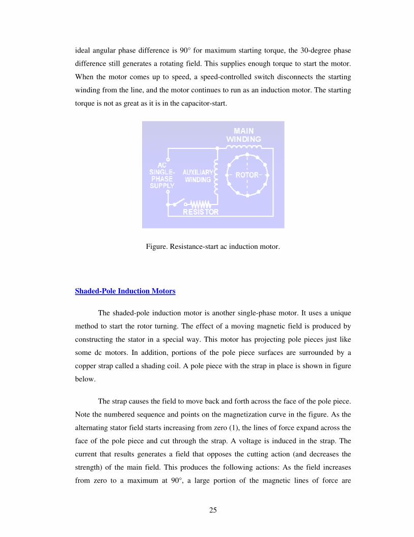
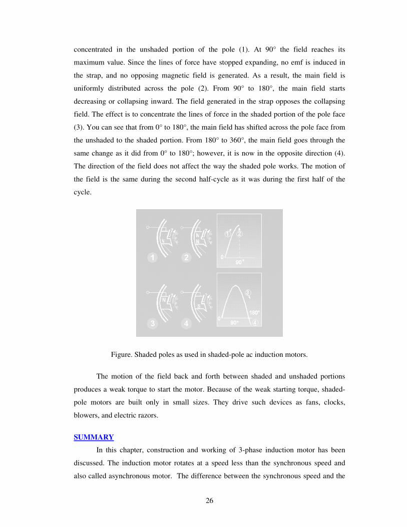
1 UNIT 3. INDUCTION MOTORS OBJECTIVE The aim of this chapter is to gather knowledge about the following topics of Induction motors. 1. Construction, types and principle of operation of 3-phase induction motors. 2. Equivalent circuit of 3-phase induction motor. 3. The performance calculation by means of finding torque, slip and efficiency. 4. Different types of starters like auto-transformer starter, star-delta starter. 5. Various methods of speed control 3-phase induction motor. 6. Principle of operation of single phase induction motor. INTRODUCTION An induction motor (IM) is a type of asynchronous AC motor where power is supplied to the rotating device by means of electromagnetic induction. The induction motor with a wrapped rotor was invented by Nikola Tesla Nikola Tesla in 1882 in France but the initial patent was issued in 1888 after Tesla had moved to the United States. In his scientific work, Tesla laid the foundations for understanding the way the motor operates. The induction motor with a cage was invented by Mikhail Dolivo-Dobrovolsky about a year later in Europe. Technological development in the field has improved to where a 100 hp (74.6 kW) motor from 1976 takes the same volume as a 7.5 hp (5.5 kW) motor did in 1897. Currently, the most common induction motor is the cage rotor motor. An electric motor converts electrical power to mechanical power in its rotor (rotating part). There are several ways to supply power to the rotor. In a DC motor this power is supplied to the armature directly from a DC source, while in an induction motor this power is induced in the rotating device. An induction motor is sometimes called a rotating transformer because the stator (stationary part) is essentially the primary side of the transformer and the rotor (rotating part) is the secondary side. Induction motors are widely used, especially polyphase induction motors, which are frequently used in industrial drives. Induction motors are now the preferred choice for industrial motors due to their rugged construction, absence of brushes (which are required in most DC motors) and the ability to control the speed of the motor.
Transcript
1
UNIT 3. INDUCTION MOTORS
OBJECTIVE
The aim of this chapter is to gather knowledge about the following topics of
Induction motors.
1. Construction, types and principle of operation of 3-phase induction motors.
2. Equivalent circuit of 3-phase induction motor.
3. The performance calculation by means of finding torque, slip and efficiency.
4. Different types of starters like auto-transformer starter, star-delta starter.
5. Various methods of speed control 3-phase induction motor.
6. Principle of operation of single phase induction motor.
INTRODUCTION
An induction motor (IM) is a type of asynchronous AC motor where power is
supplied to the rotating device by means of electromagnetic induction.
The induction motor with a wrapped rotor was invented by Nikola Tesla Nikola
Tesla in 1882 in France but the initial patent was issued in 1888 after Tesla had moved to
the United States. In his scientific work, Tesla laid the foundations for understanding the
way the motor operates. The induction motor with a cage was invented by Mikhail
Dolivo-Dobrovolsky about a year later in Europe. Technological development in the field
has improved to where a 100 hp (74.6 kW) motor from 1976 takes the same volume as a
7.5 hp (5.5 kW) motor did in 1897. Currently, the most common induction motor is the
cage rotor motor.
An electric motor converts electrical power to mechanical power in its rotor
(rotating part). There are several ways to supply power to the rotor. In a DC motor this
power is supplied to the armature directly from a DC source, while in an induction motor
this power is induced in the rotating device. An induction motor is sometimes called a
rotating transformer because the stator (stationary part) is essentially the primary side of
the transformer and the rotor (rotating part) is the secondary side. Induction motors are
widely used, especially polyphase induction motors, which are frequently used in
industrial drives.
Induction motors are now the preferred choice for industrial motors due to their
rugged construction, absence of brushes (which are required in most DC motors) and the
ability to control the speed of the motor.
2
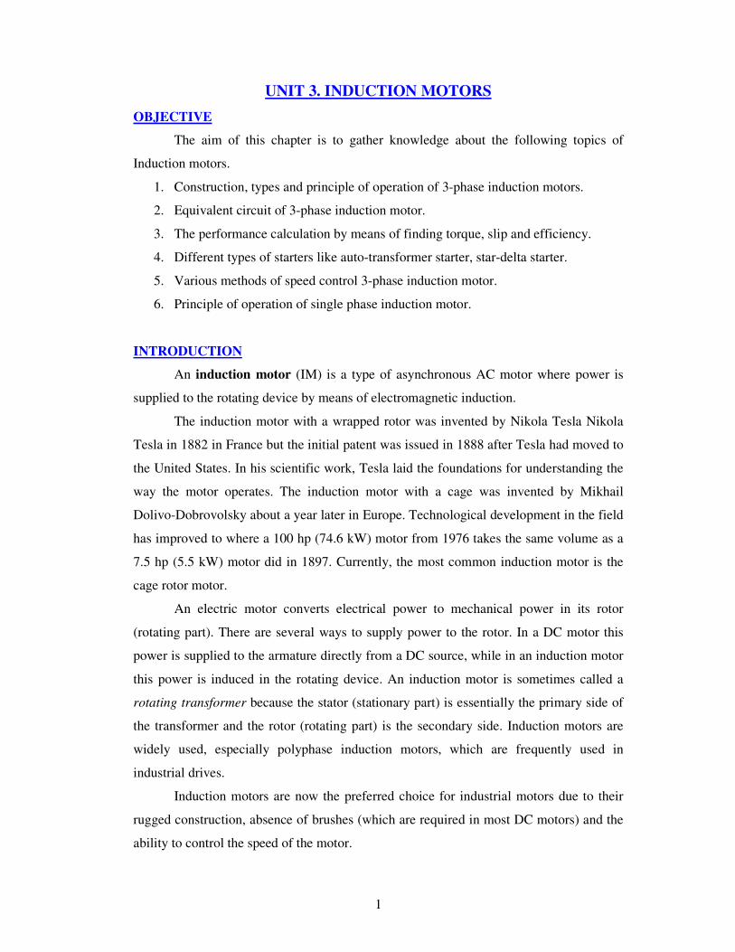
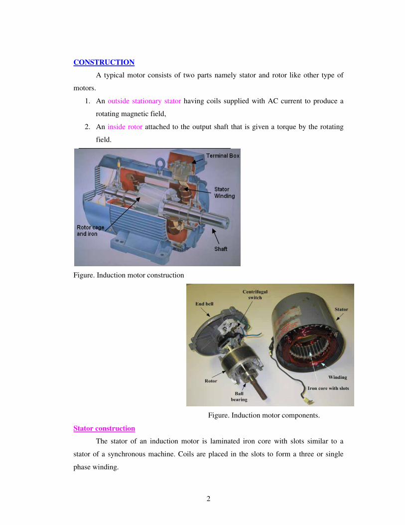
CONSTRUCTION
A typical motor consists of two parts namely stator and rotor like other type of
motors.
1. An outside stationary stator having coils supplied with AC current to produce a
rotating magnetic field,
2. An inside rotor attached to the output shaft that is given a torque by the rotating
field.
Figure. Induction motor construction
Figure. Induction motor components.
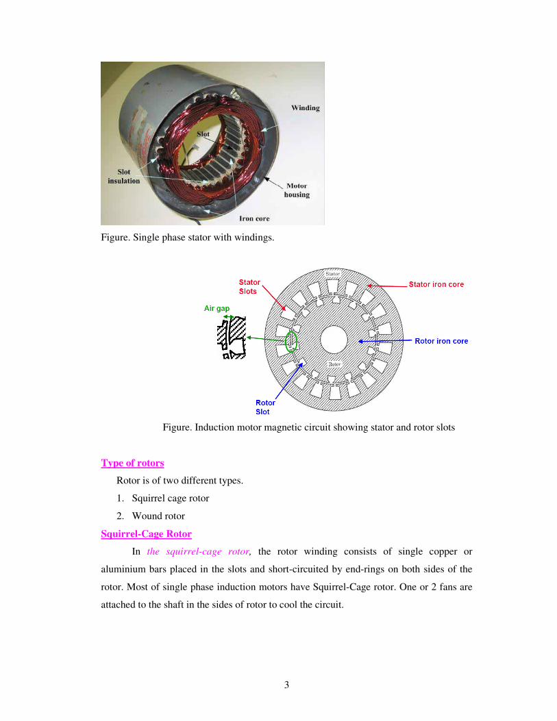
Stator construction
The stator of an induction motor is laminated iron core with slots similar to a
stator of a synchronous machine. Coils are placed in the slots to form a three or single
phase winding.
3
Figure. Single phase stator with windings.
Figure. Induction motor magnetic circuit showing stator and rotor slots
Type of rotors
Rotor is of two different types.
1. Squirrel cage rotor
2. Wound rotor
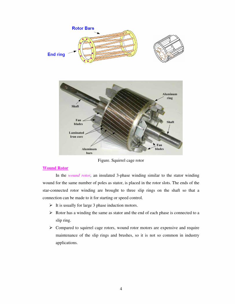
Squirrel-Cage Rotor
In the squirrel-cage rotor, the rotor winding consists of single copper or
aluminium bars placed in the slots and short-circuited by end-rings on both sides of the
rotor. Most of single phase induction motors have Squirrel-Cage rotor. One or 2 fans are
attached to the shaft in the sides of rotor to cool the circuit.
4
Figure. Squirrel cage rotor
Wound Rotor
In the wound rotor, an insulated 3-phase winding similar to the stator winding
wound for the same number of poles as stator, is placed in the rotor slots. The ends of the
star-connected rotor winding are brought to three slip rings on the shaft so that a
connection can be made to it for starting or speed control.
� It is usually for large 3 phase induction motors.
� Rotor has a winding the same as stator and the end of each phase is connected to a
slip ring.
� Compared to squirrel cage rotors, wound rotor motors are expensive and require
maintenance of the slip rings and brushes, so it is not so common in industry
applications.
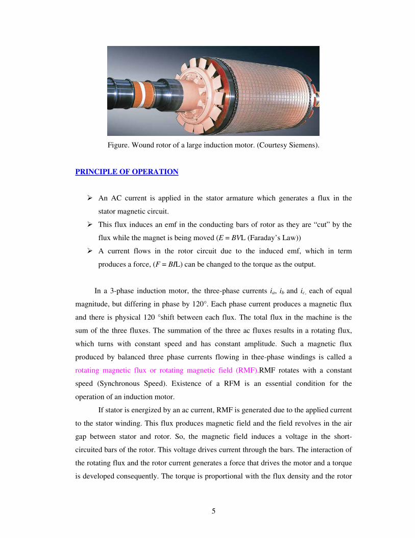
5
Figure. Wound rotor of a large induction motor. (Courtesy Siemens).
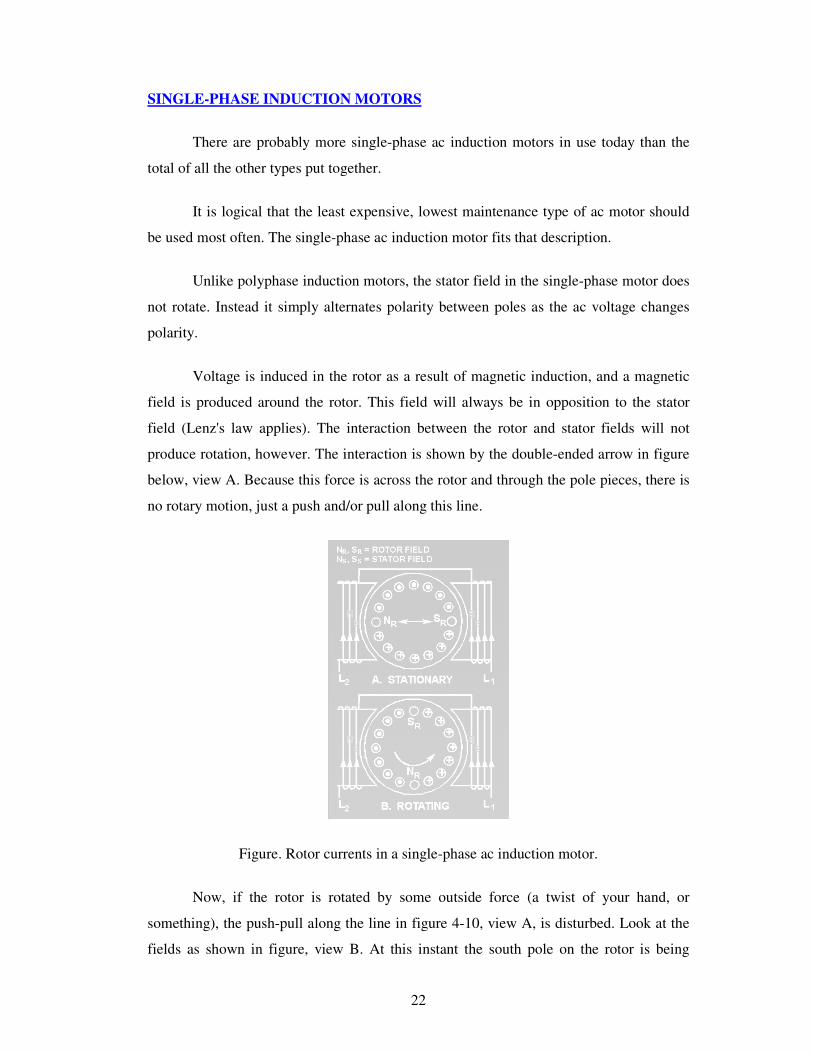
PRINCIPLE OF OPERATION
� An AC current is applied in the stator armature which generates a flux in the
stator magnetic circuit.
� This flux induces an emf in the conducting bars of rotor as they are “cut” by the
flux while the magnet is being moved (E = BVL (Faraday’s Law))
� A current flows in the rotor circuit due to the induced emf, which in term
produces a force, (F = BIL) can be changed to the torque as the output.
In a 3-phase induction motor, the three-phase currents ia, ib and ic, each of equal
magnitude, but differing in phase by 120°. Each phase current produces a magnetic flux
and there is physical 120 °shift between each flux. The total flux in the machine is the
sum of the three fluxes. The summation of the three ac fluxes results in a rotating flux,
which turns with constant speed and has constant amplitude. Such a magnetic flux
produced by balanced three phase currents flowing in thee-phase windings is called a
rotating magnetic flux or rotating magnetic field (RMF).RMF rotates with a constant
speed (Synchronous Speed). Existence of a RFM is an essential condition for the
operation of an induction motor.
If stator is energized by an ac current, RMF is generated due to the applied current
to the stator winding. This flux produces magnetic field and the field revolves in the air
gap between stator and rotor. So, the magnetic field induces a voltage in the short-
circuited bars of the rotor. This voltage drives current through the bars. The interaction of
the rotating flux and the rotor current generates a force that drives the motor and a torque
is developed consequently. The torque is proportional with the flux density and the rotor
6
bar current (F=BLI). The motor speed is less than the synchronous speed. The direction
of the rotation of the rotor is the same as the direction of the rotation of the revolving
magnetic field in the air gap.
However, for these currents to be induced, the speed of the physical rotor and the
speed of the rotating magnetic field in the stator must be different, or else the magnetic
field will not be moving relative to the rotor conductors and no currents will be induced.
If by some chance this happens, the rotor typically slows slightly until a current is re-
induced and then the rotor continues as before. This difference between the speed of the
rotor and speed of the rotating magnetic field in the stator is called slip. It is unitless and
is the ratio between the relative speed of the magnetic field as seen by the rotor the (slip
speed) to the speed of the rotating stator field. Due to this an induction motor is
sometimes referred to as an asynchronous machine.
SLIP
The relationship between the supply frequency, f, the number of poles, p, and the
synchronous speed (speed of rotating field), ns is given by
120s
fn
p=
The stator magnetic field (rotating magnetic field) rotates at a speed, ns, the
synchronous speed. If, n= speed of the rotor, the slip, s for an induction motor is defined
as
s
s
n ns
n
−=
At stand still, rotor does not rotate , n = 0, so s = 1.
At synchronous speed, n= nS, s = 0
The mechanical speed of the rotor, in terms of slip and synchronous speed is given by,
n=(1-s) ns
Frequency of Rotor Current and Voltage
With the rotor at stand-still, the frequency of the induced voltages and currents is the
same as that of the stator (supply) frequency, fe.
If the rotor rotates at speed of n, then the relative speed is the slip speed:
nslip=ns-n
nslip is responsible for induction.
7
Hence, the frequency of the induced voltages and currents in the rotor is, fr= sfe.
Example1:
Solution:
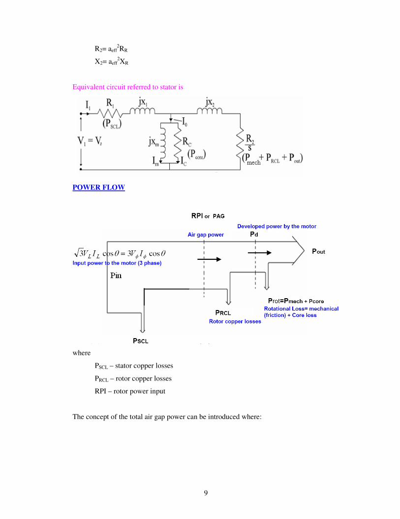
EQUIVALENT CIRCUIT
The induction motor consists of a two magnetically connected systems namely,
stator and rotor. This is similar to a transformer that also has two magnetically connected
systems namely primary and secondary windings. Also, the induction motor operates on
the same principle as the transformer. Hence, the induction motor is also called as
rotating transformer
The stator is supplied by a balanced three-phase voltage that drives a three-phase
current through the winding. This current induces a voltage in the rotor. The applied
voltage (V1) across phase A is equal to the sum of the
–induced voltage (E1).
–voltage drop across the stator resistance (I1R1).
–voltage drop across the stator leakage reactance (I1 j X1).
Let
I1 = stator current/phase
R1 = stator winding resistance/phase
X1 = stator winding reactance/phase
RR = stator winding resistance/phase
XR = stator winding reactance/phase
IR = rotor current
V1 = applied voltage to the stator/phase
Io = Ic+Im (Im-magnetising component, Ic-core loss component)
8
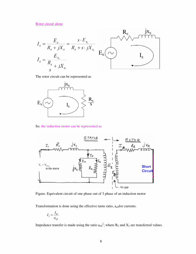
Rotor circuit alone
The rotor circuit can be represented as
So, the induction motor can be represented as
Figure. Equivalent circuit of one phase out of 3 phase of an induction motor
Transformation is done using the effective turns ratio, aefffor currents.
2R
eff
II
a=
Impedance transfer is made using the ratio aeff2; where R2 and X2 are transferred values.
9
R2= aeff2RR
X2= aeff2XR
Equivalent circuit referred to stator is
POWER FLOW
where
PSCL – stator copper losses
PRCL – rotor copper losses
RPI – rotor power input
The concept of the total air gap power can be introduced where:
10
The mechanical power however is only developed across the new variable resistance,
hence Pmech is:
As the rotor copper loss is P2 = I22R2 = sPg then a ratio of powers can be defined:
The motor torque is given by
The ideal efficiency can be determined by firstly assuming that the power transferred
across the air gap equals the input power.
Therefore efficiency is given by
The efficiency increases as the speed increases, hence an induction machine
should always be operated at low values of slip to ensure efficient (and high power
factor) operation
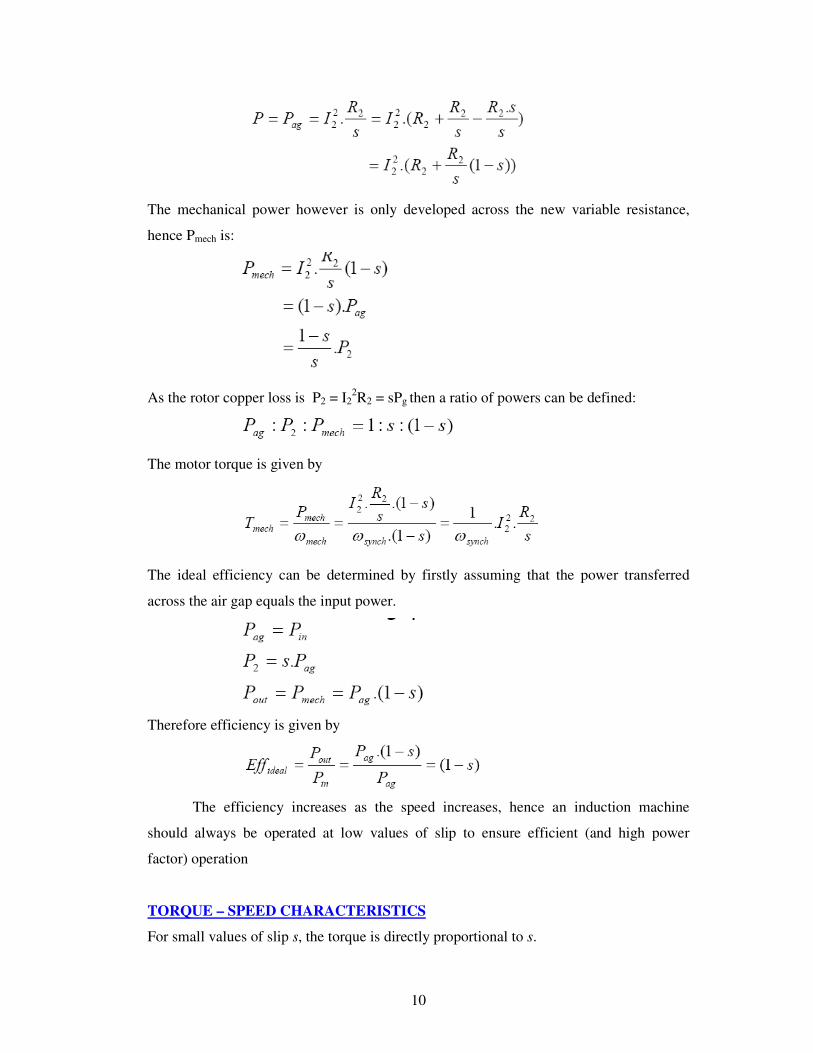
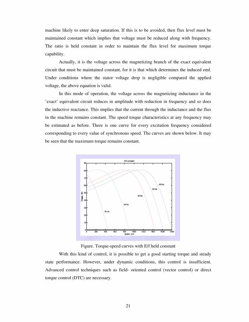
TORQUE – SPEED CHARACTERISTICS
For small values of slip s, the torque is directly proportional to s.
11
For large values of slip s, the torque is inversely proportional to s.
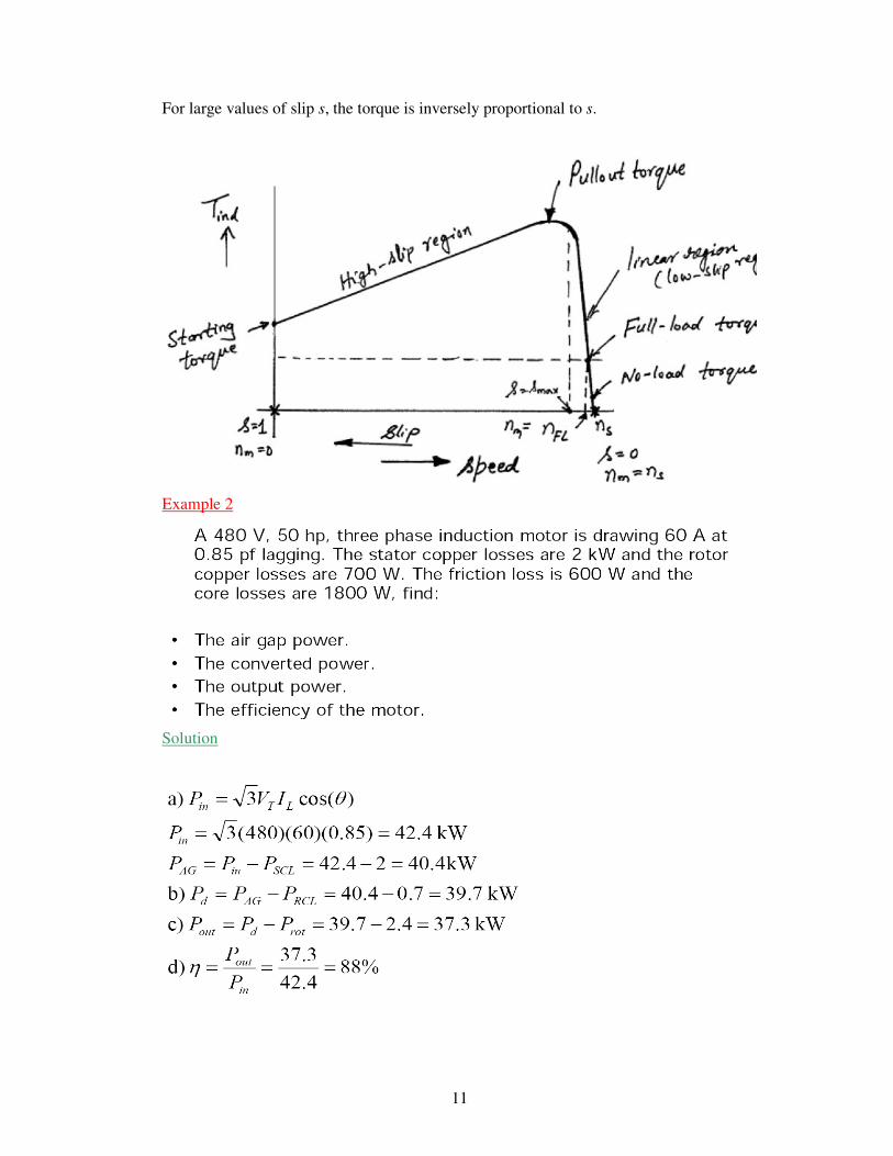
Example 2
Solution
12
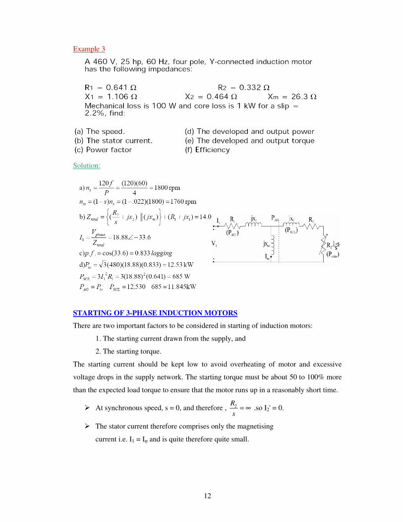
Example 3
Solution:
STARTING OF 3-PHASE INDUCTION MOTORS
There are two important factors to be considered in starting of induction motors:
1. The starting current drawn from the supply, and
2. The starting torque.
The starting current should be kept low to avoid overheating of motor and excessive
voltage drops in the supply network. The starting torque must be about 50 to 100% more
than the expected load torque to ensure that the motor runs up in a reasonably short time.
� At synchronous speed, s = 0, and therefore , 2R
s= ∞ .so I2' = 0.
� The stator current therefore comprises only the magnetising
current i.e. I1 = Iφ and is quite therefore quite small.
13
� At low speeds, 22
'RjX
s+ = ∞ is small, and therefore I2' is quite high and
consequently I1 is quite large.
� Actually the typical starting currents for an induction machine are ~ 5 to 8 times
the normal running current.
Hence the starting currents should be reduced. The most usual methods of starting 3-
phase induction motors are:
For slip-ring motors
� Rotor resistance starting
For squirrel-cage motors
� Direct-on -line starting
� Star-delta starting
� Autotransformer starting.
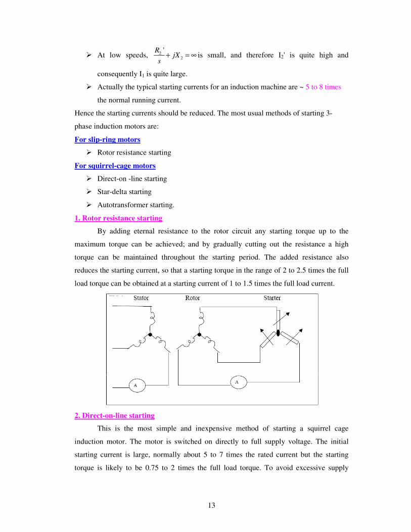
1. Rotor resistance starting
By adding eternal resistance to the rotor circuit any starting torque up to the
maximum torque can be achieved; and by gradually cutting out the resistance a high
torque can be maintained throughout the starting period. The added resistance also
reduces the starting current, so that a starting torque in the range of 2 to 2.5 times the full
load torque can be obtained at a starting current of 1 to 1.5 times the full load current.
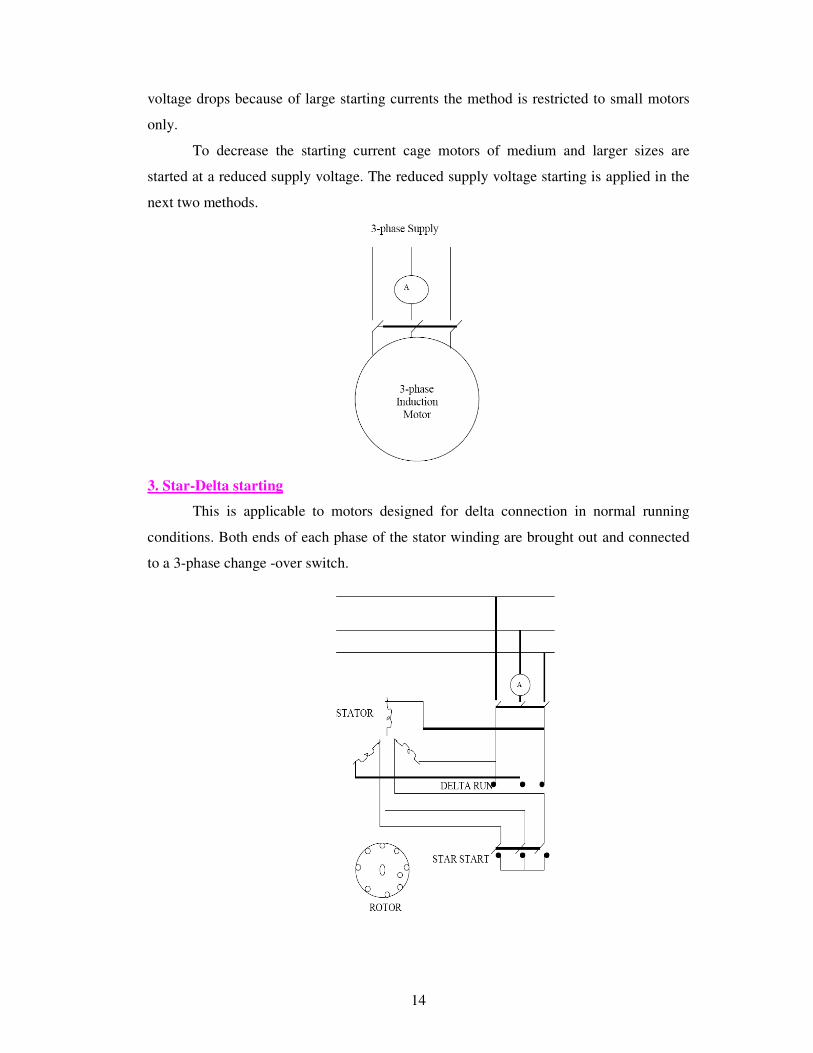
2. Direct-on-line starting
This is the most simple and inexpensive method of starting a squirrel cage
induction motor. The motor is switched on directly to full supply voltage. The initial
starting current is large, normally about 5 to 7 times the rated current but the starting
torque is likely to be 0.75 to 2 times the full load torque. To avoid excessive supply
14
voltage drops because of large starting currents the method is restricted to small motors
only.
To decrease the starting current cage motors of medium and larger sizes are
started at a reduced supply voltage. The reduced supply voltage starting is applied in the
next two methods.
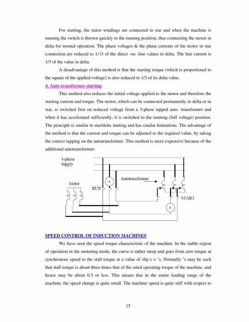
3. Star-Delta starting
This is applicable to motors designed for delta connection in normal running
conditions. Both ends of each phase of the stator winding are brought out and connected
to a 3-phase change -over switch.
15
For starting, the stator windings are connected in star and when the machine is
running the switch is thrown quickly to the running position, thus connecting the motor in
delta for normal operation. The phase voltages & the phase currents of the motor in star
connection are reduced to 1/√3 of the direct -on -line values in delta. The line current is
1/3 of the value in delta.
A disadvantage of this method is that the starting torque (which is proportional to
the square of the applied voltage) is also reduced to 1/3 of its delta value.
4. Auto-transformer starting
This method also reduces the initial voltage applied to the motor and therefore the
starting current and torque. The motor, which can be connected permanently in delta or in
star, is switched first on reduced voltage from a 3-phase tapped auto -transformer and
when it has accelerated sufficiently, it is switched to the running (full voltage) position.
The principle is similar to star/delta starting and has similar limitations. The advantage of
the method is that the current and torque can be adjusted to the required value, by taking
the correct tapping on the autotransformer. This method is more expensive because of the
additional autotransformer.
SPEED CONTROL OF INDUCTION MACHINES
We have seen the speed torque characteristic of the machine. In the stable region
of operation in the motoring mode, the curve is rather steep and goes from zero torque at
synchronous speed to the stall torque at a value of slip s = ˆs. Normally ˆs may be such
that stall torque is about three times that of the rated operating torque of the machine, and
hence may be about 0.3 or less. This means that in the entire loading range of the
machine, the speed change is quite small. The machine speed is quite stiff with respect to
16
load changes. The entire speed variation is only in the range ns to (1 − s)ns, ns being
dependent on supply frequency and number of poles.
The foregoing discussion shows that the induction machine, when operating from
mains is essentially a constant speed machine. Many industrial drives, typically for fan or
pump applications, have typically constant speed requirements and hence the induction
machine is ideally suited for these. However, the induction machine, especially the
squirrel cage type, is quite rugged and has a simple construction. Therefore it is good
candidate for variable speed applications if it can be achieved.
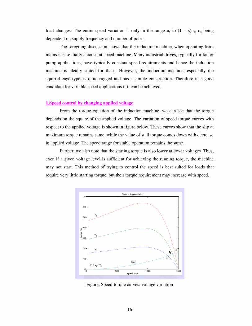
1.Speed control by changing applied voltage
From the torque equation of the induction machine, we can see that the torque
depends on the square of the applied voltage. The variation of speed torque curves with
respect to the applied voltage is shown in figure below. These curves show that the slip at
maximum torque remains same, while the value of stall torque comes down with decrease
in applied voltage. The speed range for stable operation remains the same.
Further, we also note that the starting torque is also lower at lower voltages. Thus,
even if a given voltage level is sufficient for achieving the running torque, the machine
may not start. This method of trying to control the speed is best suited for loads that
require very little starting torque, but their torque requirement may increase with speed.
Figure. Speed-torque curves: voltage variation
17
The figure above also shows a load torque characteristic, one that is typical of a
fan type of load. In a fan (blower) type of load, the variation of torque with speed is such
that T α ω2. Here one can see that it may be possible to run the motor to lower speeds
within the range ns to (1 − s)ns. Further, since the load torque at zero speed is zero, the
machine can start even at reduced voltages. This will not be possible with constant torque
type of loads. One may note that if the applied voltage is reduced, the voltage across the
magnetizing branch also comes down. This in turn means that the magnetizing current
and hence flux level are reduced. Reduction in the flux level in the machine impairs
torque production, which is primarily the explanation for figure.
If, however, the machine is running under lightly loaded conditions, then
operating under rated flux levels is not required. Under such conditions, reduction in
magnetizing current improves the power factor of operation. Some amount of energy
saving may also be achieved. Voltage control may be achieved by adding series resistors
(a lossy, inefficient proposition), or a series inductor / autotransformer (a bulky solution)
or a more modern solution using semiconductor devices. A typical solid state circuit used
for this purpose is the AC voltage controller or AC chopper. Another use of voltage
control is in the so-called ‘soft-start’ of the machine. This is discussed in the section on
starting methods.
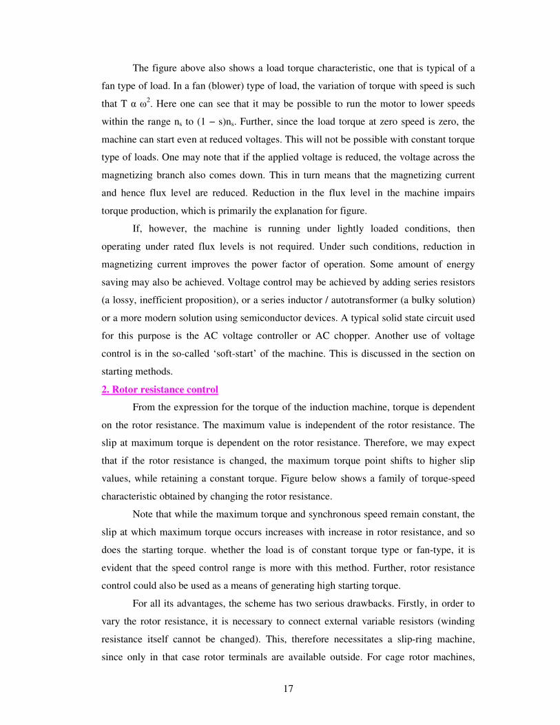
2. Rotor resistance control
From the expression for the torque of the induction machine, torque is dependent
on the rotor resistance. The maximum value is independent of the rotor resistance. The
slip at maximum torque is dependent on the rotor resistance. Therefore, we may expect
that if the rotor resistance is changed, the maximum torque point shifts to higher slip
values, while retaining a constant torque. Figure below shows a family of torque-speed
characteristic obtained by changing the rotor resistance.
Note that while the maximum torque and synchronous speed remain constant, the
slip at which maximum torque occurs increases with increase in rotor resistance, and so
does the starting torque. whether the load is of constant torque type or fan-type, it is
evident that the speed control range is more with this method. Further, rotor resistance
control could also be used as a means of generating high starting torque.
For all its advantages, the scheme has two serious drawbacks. Firstly, in order to
vary the rotor resistance, it is necessary to connect external variable resistors (winding
resistance itself cannot be changed). This, therefore necessitates a slip-ring machine,
since only in that case rotor terminals are available outside. For cage rotor machines,
18
there are no rotor terminals. Secondly, the method is not very efficient since the
additional resistance and operation at high slips entails dissipation.