46
PIPELINING AND PARALLEL PROCESSING UNIT 4 Real time Signal Processing

PIPELINING AND PARALLEL PROCESSINGUNIT 4
Real time Signal Processing

Contents
Introduction
Pipeling of FIR Digital FiltersPipeling of FIR Digital Filters
Parallel processing
Low power Design

FIR Digital Filter
� A FIR Filter is defined as follows:
� For example:( ) ( )∑ −=
kk knxany
( ) ( ) ( ) ( )21 −⋅+−⋅+⋅= nxcnxbnxany( ) ( ) ( ) ( )21 −⋅+−⋅+⋅= nxcnxbnxany
z-1 z-1
b ca
+ +
x(n)
y(n)

Signal Flow Graph
� Another way to represent DSP signals is by SFG.
� SFG is a collection of nodes and directed edges.
� Node represents a computations or tasks
� Node is basically a multiplier or an adder.� Node is basically a multiplier or an adder.
� Edge (j,k) is a branch from node j to node k and represents a linear transformation from the signal at node j to the signal at node k.
� Edge are restricted to constant gain multipliers, delay elements

Example
z-1 z-1
b ca
x(n)
+ + y(n)
z-1 z-1x(n)
y(n)
a b c

Exercise
� Perform the block diagram and SFG of the following examples:
( ) ( ) ( ) ( ) ( )32212 −+−⋅−−⋅−= nxnxnxnxny
( ) ( ) ( ) ( )112 −−=−⋅− nxnxnyny
( ) ( ) ( ) ( ) ( )32212 −+−⋅−−⋅−= nxnxnxnxny

Critical Path
� Critical path is the longest path in the SFG.
z-1 z-1x(n)
x(n)a b c
� As can be seen in this example, the longest path is marked in red and is composed by� 1 multiplier
� 2 additions
x(n)
Sampling Frequency
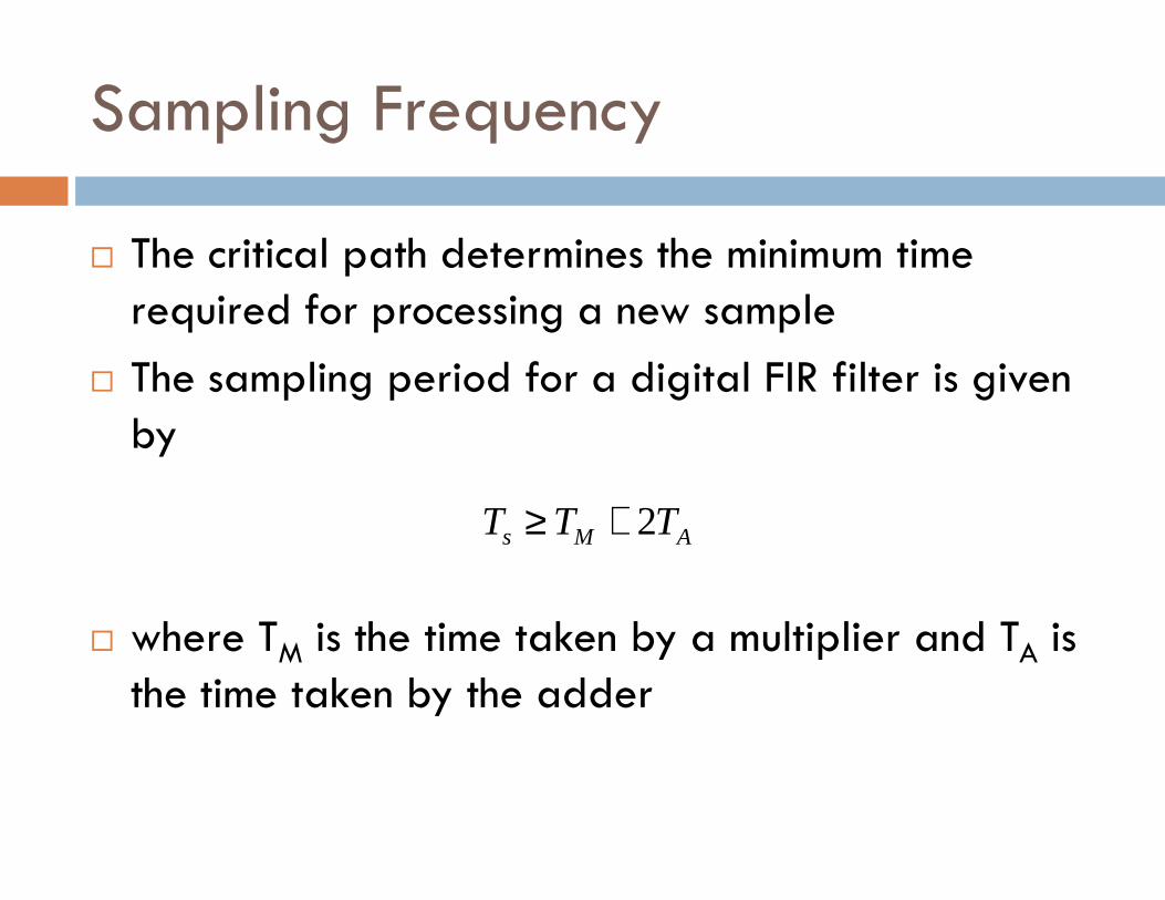
� The critical path determines the minimum time required for processing a new sample
� The sampling period for a digital FIR filter is given byby
� where TM is the time taken by a multiplier and TA is the time taken by the adder
AMs TTT 2+≥

Sampling frequency
� The sampling frequency is given by
� Sampling frequency is limited by the critical path
AMs TT
f2
1+
≤
� Sampling frequency is limited by the critical path
� The direct-form structure can only by used when this equation can be satisfied.
� Some real-time applications demands faster input rate (sampling frequency)

Pipelining and Parallel Processing
� Pipeling transformation leads to a reduction in the critical path, this
� Multiple outputs are compute in parallel for in a clock period
Pipeling Parallel
the critical path, this reduction leads to� Increase clock speed
� Increase sampling frequency
� Reduce power consumption
in a clock period
� This approach can also be use for reduction of power consumption

Pipelining and Parallel Processing
� Reduction of the critical path is achieved by
� Parallel processing reduces the sampling rate by replicating
Pipeling Parallel
achieved by introducing pipelinglatches
rate by replicating hardware so that several inputs can be processes at the same time
Pipeling of FIR Digital Filters
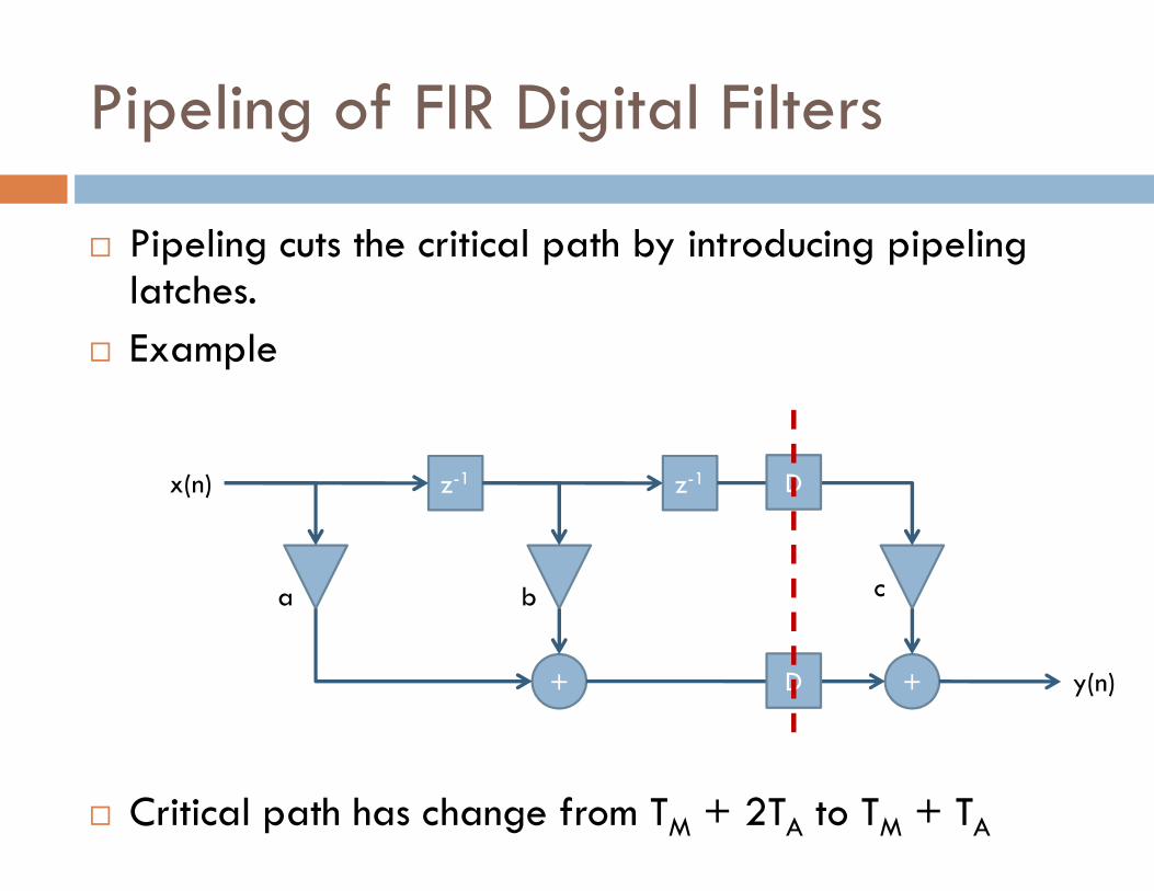
� Pipeling cuts the critical path by introducing pipelinglatches.
� Example
� Critical path has change from TM + 2TA to TM + TA
z-1 z-1
b ca
+ +
x(n)
y(n)
D
D

Pipeling of FIR Digital Filters
� The schedule of events for the pipeling system is shown in the following table
Clock Input Node 1 Node 2 Node 3 Output
0 x(0) a x(0) + b x(-1) - - -
� At any time, 2 consecutive outputs are computed in a interleaved manner
0 x(0) a x(0) + b x(-1) - - -
1 x(1) a x(1) + b x(0) a x(0) + b x(-1) c x(-2) y(0)
2 x(2) a x(2) + b x(1) a x(1) + b x(0) c x(-1) y(1)
3 x(3) a x(3) + b x(2) a x(2) + b x(1) c x(0) y(2)

Pipeling of FIR Digital Filters
� In an M-level pipeline system, the number of delay elements in any path from the input to the output is (M-1) greater than the original system.
� Pipelining reduces the critical path but increases the � Pipelining reduces the critical path but increases the latency.
� Latency is the difference in the availability of the first output data
� The drawbacks of pipelining is the increase in the number of latches and the system latency

Pipeling of FIR Digital Filters
� The speed of an architecture is limited by the longest path between 2 latches
� The longest path can be reduced by placing pipeline latches pipeline latches
� The pipeling latches can only be placed accrosfeed-forward cutset of the graph� feed-forward cutset is a set of edges (all on the
forward direction) that if they are removed the graph becomes disjoint

Data broadcast structure
� The critical path of the original 3-tap FIR filter can be reduced without introducing any pipeling latch by transposing the structure
� Transposing theorem
� Reversing the direction of all the edges in a given SFG and interchanging the input and output ports preserves the functionality of the system

Transposing
z-1 z-1x(n)
y(n)
a b c
y(n)
z-1 z-1y(n)
x(n)
a b c
Data broadcast
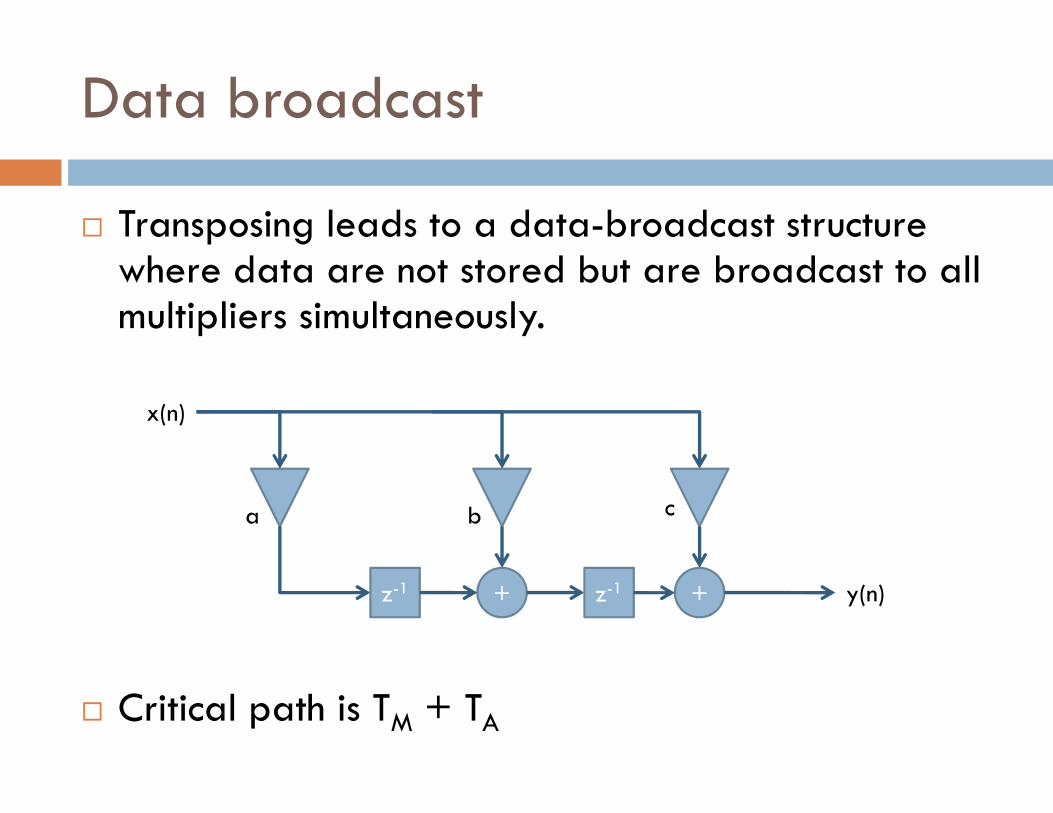
� Transposing leads to a data-broadcast structure where data are not stored but are broadcast to all multipliers simultaneously.
x(n)
� Critical path is TM + TA
b ca
+ +
x(n)
y(n)z-1 z-1

Fine-Grain Pipelining
� Let TM = 10 units and TA = 2 units and the desired clock period is (TM + TA)/2 = 6 units
� Then, the TM must be split into 2 smaller units with processing time 6 units and 4 units.
x(n)
b ca
+ +
x(n)
y(n)z-1 z-1
M1
M2
D
M1
M2
D
M1
M2
D

Parallel Processing
� Pipeline and parallel techniques are dual of each other
� Pipeline processes data in interleaved fashion while � Pipeline processes data in interleaved fashion while parallel systems process more than one data using duplicated hardware.
� The system must be transformed to receive multiple data to be process by the parallel architecture

Parallel FIR Filter
� Consider the Single-Input-Single-Output (SISO) filter describe as follows:
( ) ( ) ( ) ( )21 −⋅+−⋅+⋅= nxcnxbnxany
� To obtain a parallel processing structure, the SISO system must be converted into a Multiple-Input-Multiple-Output (MIMO) system
( ) ( ) ( ) ( )21 −⋅+−⋅+⋅= nxcnxbnxany
Parallel FIR Filter
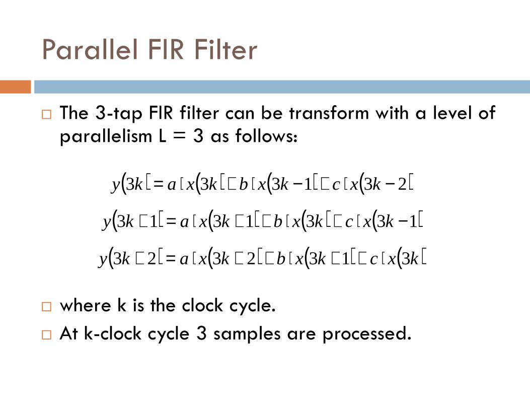
� The 3-tap FIR filter can be transform with a level of parallelism L = 3 as follows:
( ) ( ) ( ) ( )231333 −⋅+−⋅+⋅= kxckxbkxaky
� where k is the clock cycle.
� At k-clock cycle 3 samples are processed.
( ) ( ) ( ) ( )1331313 −⋅+⋅++⋅=+ kxckxbkxaky
( ) ( ) ( ) ( )kxckxbkxaky 3132323 ⋅++⋅++⋅=+

MIMO Structure
x(3k)
y(3k)
b ca
+ +z-1 z-1
x(3k+1)
b ca
+ +z-1 z-1
b ca
+ +z-1 z-1
x(3k+1)
x(3k+2)
y(3k+1)
y(3k+2)

MIMO Structure
� The critical path of the block or parallel processing system has remained unchanged and the clock period Tclk must satisfy
AMclk TTT 2+≥
� But since 3 samples are processed in 1 clock cycle, the sampling frequency is given by
AMclk TTT 2+≥
( )AMclks TTTT 231
31 +≥=

Parallel FIR Filter
Serial-to-Parallel Converter
x(n)
Sample Period TCLK/4
Sample Period TCLK/4
Parallel-to-Serial Converter
MIMO System
y(n)
Clock Period TCLK

Serial to Parallel Converter
D D Dx(n)
T/4 T/4 T/4
T
x(4k+3) x(4k+2) x(4k+1) x(4k)
T

Parallel to Serial Converter
y(4k+3) y(4k+2) y(4k+1) y(4k)
T
D D D y(n)
T/4 T/4 T/4
T

Parallel and Pipelining Processing
� Fine-grain pipeling can be applied to reduce the critical path.
� Combining parallel structure with fine-grain � Combining parallel structure with fine-grain pipelining applied to the multiplier, the sample period has been further reduce to
( )AMclks TTTLM
T 223
11 +⋅
≥=

Why apply parallelism ?
� There is a fundamental limit to pipeling impose by the input/output bottleneck
T
� If the input-pad delay, output-pad delay and the wire delay between two chips is 8 nsec, then TCLK
has to be greater or equal to 8 nsec.
Output pad
Input pad
Tcommunication

Communication bounded
� If the communication time is greater than the processing time of the critical path, then the system is communication bounded.
� Then, pipeling can be used only to the extent such that the critical path computation is limited by the communication or I/O bound, and once this has been reached, pipelining can no longer increase the speed

Low Power
Pipeling and parallel processing for low power

Low power
� The two main advantages of using pipeling and parallel processing are:
� Higher speed
� Lower power� Lower power
� The propagation delay is associated with charging and discharging of various gate and stray capacitances in the critical path
( )2ts
scpd
VVk
VCT
−=

Power Consumption
� The power consumption of a CMOS circuit can be estimated using the following equation
fVCP 2=
� Ctotal denotes the total capacitance of the circuit
� Vs supply voltage
� f is the clock frequency of the circuit
fVCP stotal=

Pipeling for low power
� Lets define the power consumed by a FIR filter without pipeling as
fVCP stotalseq2=
� Consider an M-level pipeline system, where the critical path is reduced to 1/M, then Cc is reduced to Cc/M for a single clock cycle.
� In the same time that Cc was charge/discharge, now only a fraction of it should be charge/discharge

Pipeline for low power
� Then, the supply voltage can be reduced by β, where 0 < β < 1
� The power consumption of the pipeline filter will be
� The value of β can be determined by examining the propagation delay
seqstotalpip PfVCP 222 ββ ==
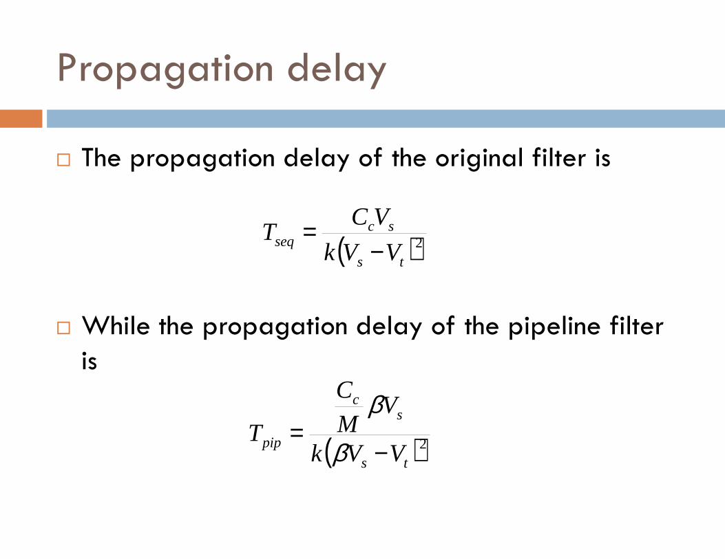
Propagation delay
� The propagation delay of the original filter is
( )2ts
scseq
VVk
VCT
−=
� While the propagation delay of the pipeline filter is
( )2ts
sc
pipVVk
VM
C
T−
=β
β

Propagation delay
� The same clock speed is maintained for both filters, therefore the following equation is maintained
( ) ( )20
2tts VVVVM −=− ββ
� Then β is obtained , the reduction of power consumption can be computed using
seqstotalpip PfVCP 222 ββ ==
( ) ( )0 tts VVVVM −=− ββ

Example
� Supose that the capacitance of the multiplier is 5 times the capacitance of the adder.
� What is the supply voltage of the pipeline filter?
� What is the power consumption of the pipeline filter?
� The M1 has 3 times and M2 has 2 times the adder capacitance
� Vt = 0.6V and Vs=5.0 V
b ca
+ + y(n)z-1 z-1
M1
M2
D
M1
M2
D
M1
M2
D
6 units
4 units
2 units
consumption of the pipeline filter?

Parallel Processing for Low Power
� In parallel processing the total capacitance is not reduced, rather is increase by L times.
� In order to maintain the same data rate, the clock period must be increased to LTperiod must be increased to LTseq
� Then, there is more time to charge the same capacitance.
� Therefore, the supply voltage can be reduced to βVs

Propagation delay
� The propagation delay of the original filter is
( )2ts
scseq
VVk
VCT
−=
� While the propagation delay of the parallel filter filter is
( )2ts
scseqpar
VVk
VLCLTT
−==
ββ

Propagation delay
� The same clock speed is maintained for both filters, therefore the following equation is maintained
( ) ( )20
2tts VVVVL −=− ββ
� Then β is obtained , the reduction of power consumption can be computed using
( ) seqsechscpar PfVCL
fVLCP 22
arg22 βββ ===
( ) ( )0 tts VVVVL −=− ββ

Example
� Consider a 4-tap FIR filter and a L=2 parallel filter.
� Assume that the multiplication operation takes 8 ut and the addition 1 ut
� Assume that the capacitance of the multiplier is 8 times that of an adder.times that of an adder.
� The two architecture are operated at a sample period of 9 ut
� Vt = 0.45V and Vs= 3.3 V� What is the supply voltage of the 2-parallel filter?
� What is the power consumption of the 2 parallel filter?

Combining Parallel and Pipeling
� Pipeling reduces the capacitance to be charged/discharge in 1 clock period. 3T 3T
� Parallel processing increases the clock period for charging/discharging the original capacitance.
3T 3T
3T 3T
T

Propagation delay
� The propagation delay of the original filter is
( )2ts
scseq
VVk
VCT
−=
� While the propagation delay of the parallel filter filter is
( )( )2
0
ts
scpippp
VVk
VMCLLTT
−==
ββ

Propagation delay
� The same clock speed is maintained for both filters, therefore the following equation is maintained
( ) ( )20
2tts VVVVML −=− ββ
� Then β is obtained , the reduction of power consumption can be computed using
seqpp PP 2β=
( ) ( )0 tts VVVVML −=− ββ

Example
� Considering L = M = 2, Vs = 5V and Vt = 0.6V. Then β = 0.4
� The power consumption is reduced by a factor of � The power consumption is reduced by a factor of 0.16; Ppp= 0.16Pseq
� However, there is a limit impose by the threshold voltage. The supply voltage cannot be lower than Vt


