UNIT-4 SATELLITE COMMUNICATION SYSTEM MALLIKARJUN S H, LECTURER GPT KAMPLI 1 SATELLITE COMMUNICATION SYSTEM If a transmitting station cannot communicate directly with one or more receiving stations because of line-of-sight limitations, then a satellite can be used. The transmitting station sends the information to the satellite which, in turn. retransmits it to the receiving stations. The satellite in this application is known as a repeater. Communications satellite repeater Fig. 4.1: Satellite communications system Fig. 4.1 show the basic operation of a communications satellite. An earth station transmits information to the satellite on an RF carrier called the uplink. A typical up-link frequency is 6 GHz. The satellite contains a receiver which picks up the transmitted signal. amplifies it and translates it to another frequency This new frequency is then retransmitted to the receiving stations back on earth. The transmitter-receiver combination in the satellite is known as a transponder. The basic function of a transponder is amplification and frequency translation. Retransmitted signal from the satellite to the receiving stations is called the down link. The downlink frequency is lower than the up-link frequency. A common down-link frequency is 4 GHz. The downlink frequencies are kept different from the uplink frequencies in order to avoid interference. station
Transcript
UNIT-4 SATELLITE COMMUNICATION SYSTEM
MALLIKARJUN S H, LECTURER GPT KAMPLI 1
SATELLITE COMMUNICATION SYSTEM
If a transmitting station cannot communicate directly with one or more receiving stations
because of line-of-sight limitations, then a satellite can be used. The transmitting station sends
the information to the satellite which, in turn. retransmits it to the receiving stations. The satellite
in this application is known as a repeater.
Communications
satellite repeater
Fig. 4.1: Satellite communications system
Fig. 4.1 show the basic operation of a communications satellite. An earth station
transmits information to the satellite on an RF carrier called the uplink. A typical up-link
frequency is 6 GHz. The satellite contains a receiver which picks up the transmitted
signal. amplifies it and translates it to another frequency This new frequency is then
retransmitted to the receiving stations back on earth. The transmitter-receiver
combination in the satellite is known as a transponder. The basic function of a
transponder is amplification and frequency translation. Retransmitted signal from the
satellite to the receiving stations is called the down link. The downlink frequency is lower
than the up-link frequency. A common down-link frequency is 4 GHz. The downlink
frequencies are kept different from the uplink frequencies in order to avoid interference.
station
UNIT-4 SATELLITE COMMUNICATION SYSTEM
MALLIKARJUN S H, LECTURER GPT KAMPLI 2
TRANSPONDER
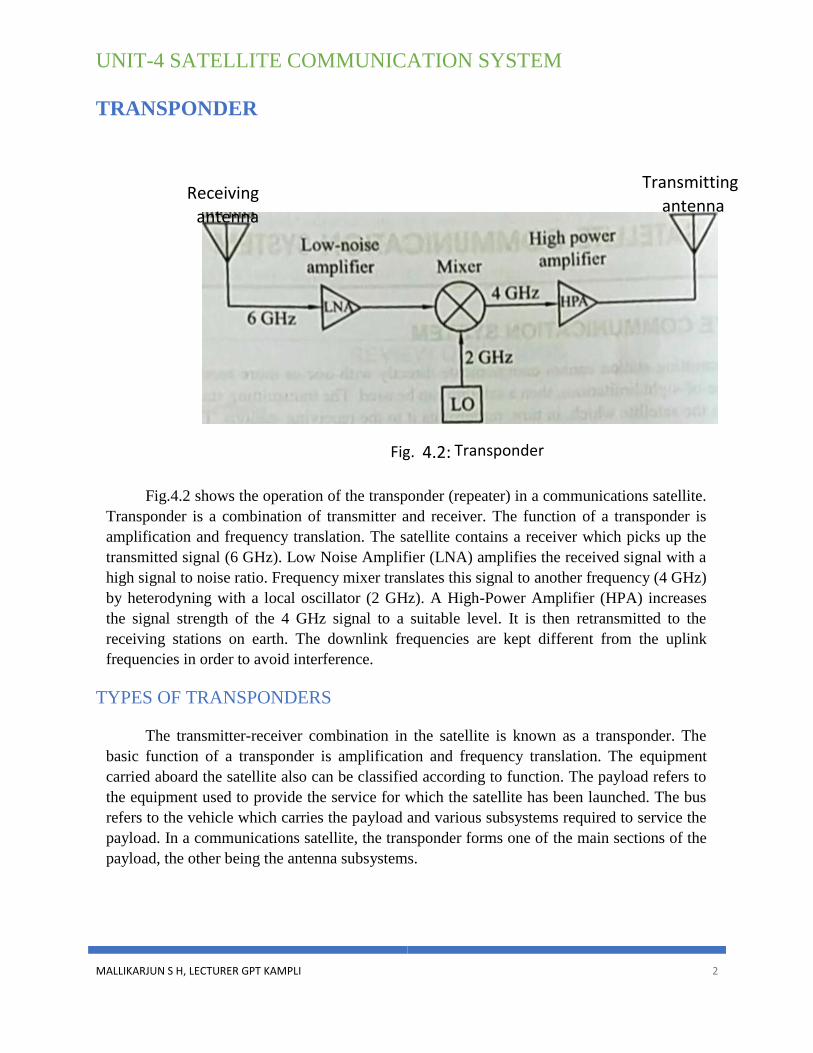
Fig.4.2 shows the operation of the transponder (repeater) in a communications satellite.
Transponder is a combination of transmitter and receiver. The function of a transponder is
amplification and frequency translation. The satellite contains a receiver which picks up the
transmitted signal (6 GHz). Low Noise Amplifier (LNA) amplifies the received signal with a
high signal to noise ratio. Frequency mixer translates this signal to another frequency (4 GHz)
by heterodyning with a local oscillator (2 GHz). A High-Power Amplifier (HPA) increases
the signal strength of the 4 GHz signal to a suitable level. It is then retransmitted to the
receiving stations on earth. The downlink frequencies are kept different from the uplink
frequencies in order to avoid interference.
TYPES OF TRANSPONDERS
The transmitter-receiver combination in the satellite is known as a transponder. The
basic function of a transponder is amplification and frequency translation. The equipment
carried aboard the satellite also can be classified according to function. The payload refers to
the equipment used to provide the service for which the satellite has been launched. The bus
refers to the vehicle which carries the payload and various subsystems required to service the
payload. In a communications satellite, the transponder forms one of the main sections of the
payload, the other being the antenna subsystems.
antenna antenna
Receiving Transmitting
Fig. 4.2: Transponder
UNIT-4 SATELLITE COMMUNICATION SYSTEM
MALLIKARJUN S H, LECTURER GPT KAMPLI 3
There are three transponder configurations:
1. Single-conversion transponder
2. Double-conversion transponder
3. Regenerative transponders
SINGLE CONVERSION TRANSPONDER
Fig. 4.3 shows a basic block diagram of a single-conversion transponder. The term
"single conversion" implies that frequency translation is done only once within the satellite.
The uplink signal is picked up by the receiving antenna and is first routed to a low-noise
amplifier (LNA)
Fig. 4.3: Single-conversion transponder
Amplifier with an extremely low noise figure must be used to increase the level of the
signal. The output of the LNA is frequency-translated in a mixer circuit. Any original
modulation is retained during the frequency translation process. The mixer output (downlink
signal) is amplified by a high-power amplifier (HPA) such as travelling wave tube (TWT)
and fed to a band pass filter. The purpose of the band pass filter is to allow only the desired
downlink signal of4 GHz and eliminate harmonics and intermodulation components. The
resulting output is fed to the downlink antenna. In some cases, a single antenna is used for
both transmission and reception. The duplexer is a waveguide assembly that allows one
antenna to be shared by a transmitter and a receiver.
DOUBLE CONVERSION TRANSPONDER
Fig. 4.4 shows a simplified block diagram of a double-conversion transponder. It is
similar to a single-conversion transponder. The only difference is that two frequency
conversions are carried out. The uplink signal is picked up by the antenna, amplified by the
LNA and fed to the first mixer. The mixer translates the incoming signal into an IF. Typical
IFS are 70 and 150 MHz
Mixer Antenna Antenna
LO
UNIT-4 SATELLITE COMMUNICATION SYSTEM
MALLIKARJUN S H, LECTURER GPT KAMPLI 4
Fig. 4.4: Double-conversion transponder
The IF signal from the first mixer is fed to an IF amplifier where very high gain is
achieved. The output of the IF amplifier is fed to another mixer which translates the signal to
the downlink frequency. Band pass filter selects only the downlink frequency and eliminates
the unwanted mixer output. The HPA increases the signal level. The output band pass filter
eliminates the harmonics and intermodulation components. The resulting output is fed to the
down-link antenna.
Merits
➢ Greater flexibility in filtering and amplification.
➢ Amplification and selectivity at the lower IF level is easier to achieve.
➢ Switching is simpler at intermediate frequencies. Switching is the process of
cross-connecting the channels in satellites employing multiple transponders.
REGENERATIVE TRANSPONDER
Like the other configurations, regenerative transponder performs the basic amplification and
frequency translation functions. But in this case, the received signal is demodulated.
remodulation is necessary to create the downlink signal.
Mixer Mixer Antenna Antenna
LO LO
UNIT-4 SATELLITE COMMUNICATION SYSTEM
MALLIKARJUN S H, LECTURER GPT KAMPLI 5
Fig. 4.5: Regenerative transponder
The block diagram of a regenerative transponder is shown in Fig. 4.5. The uplink signal is
picked up by the receiving antenna and is first routed to a low-noise amplifier (LNA).
Amplifier with an extremely low noise figure must be used to increase the level of the signal.
Once the uplink signal has been amplified, it is frequency-translated in a mixer circuit. Any
original modulation is retained during the frequency translation process. Demodulator is used
for recovering the baseband signal (voice, video or digital data). Some amplification may be
provided to this signal. Next, the baseband signal is fed to a frequency modulator along with a
carrier at the downlink frequency. The output of the modulator is amplified, filtered and
transmitted over the downlink.
Merits
❖ In a regenerative transponder, the receiver ends at the demodulator output. The
transmitter begins at the modulator input. This separation permits each section to be
fully optimized in performance. In the other configurations, this demarcation is difficult
to make.
❖ The amplification is easier to obtain at the baseband frequencies.
❖ The circuits are simpler and less expensive.
❖ The SIN ratio of the transponder can be improved.
❖ In multi-transponder satellites with input and output switching, the regenerative
arrangement is simpler and more flexible to implement. It is easier to switch baseband
signals than higher frequency signals. This flexibility allows a wider variety of
switching options to be implemented.
Mixer Antenna
Antenna
L
O
UNIT-4 SATELLITE COMMUNICATION SYSTEM
MALLIKARJUN S H, LECTURER GPT KAMPLI 6
SATELLITE FREQUENCY ALLOCATION
Most communications satellites operate in the microwave frequency spectrum.
However, there are some exceptions to this. For example, many military and amateur radio
satellites operate in the 200 - 400 MHz UHF range. The microwave spectrum is divided up into
frequency bands
which have been allocated to satellites as well as other communications services such
as radar. These frequency bands are generally designated by a letter of the alphabet.
Table. 4.1 shows the various frequency bands used in satellite communications.
Frequency, GHz Ban Purpose
0.225 -0390 P Military
0.350-0530 J Military
1.53 -2.7 L Military
2.5 - 2.7 S Commercial
3.4 - 6.425 C Commercial
7.250 - 8.400 X Military
10.95 - 14.5 Commercial
17.7-21.2 Kc Commercial
27.5 -31 K Commercial
36 -46 Q Military
46 - 56 V Military
56- 100 W Military
Table. 4.1: Satellite frequency bands
The most widely used satellite communications band is the C band. It is widely used for
television network feeds, transmissions to cable-television head-ends and some Direct
Broadcast Satellite (DBS) services. The frequencies designated for the C band uplink and
downlink are 5925 - 6425 MHz and 3700 -4200 MHz respectively. Occasionally C band is
referred to by the designation 6 GHz/4 GHz where the up-link frequency is given first.
Although most satellite communications activity takes place in the C band, there is a
steady move toward the higher frequencies such as Ku band. The reason for this shift upward
in frequency is that the C band is becoming overcrowded. The frequencies designated for the
Ku band uplink and downlink are 14 - 14.5 GHz and 11.7 - 12.2 GHz respectively. The Ku
band is designated as 14/12 GHz.
UNIT-4 SATELLITE COMMUNICATION SYSTEM
MALLIKARJUN S H, LECTURER GPT KAMPLI 7
The electronic equipment needed to achieve higher frequencies is more complex and
expensive. For a given antenna size, the gain is higher in the Ku band than in the C band. This
can improve communications reliability while decreasing antenna size and cost. This makes the
Ku-band popular for the newer direct-to-home (DTH) and direct-broadcast satellite (DBS)
systems.
Two other bands of interest are the X and L bands. The military uses the X band for its
satellites and radar, and the L band is used in marine and aeronautical communications and
radar.
SATELLITE BANDWIDTH
The satellite bandwidth is 500 MHz which is capable of carrying a large number of
signals. The 500 MHz bandwidth is divided into 12 segments, each 36 MHz wide. A
transponder is used to cover each segment which is capable of carrying an enormous amount of
information.
INCREASING CHANNEL CAPACITY
Many techniques have been developed to effectively increase the bandwidth and signal
carrying capacity of the satellite. Two of these techniques are:
l. Frequency reuse
2. Spatial isolation
FREQUENCY REUSE
Frequency reuse doubles the bandwidth and information carrying capacity of a satellite.
In this system, a communications satellite is provided with two identical sets of 12
transponders which transmit in the same frequency spectrum without interference. The two
systems are isolated from one another by the use of antennas with different polarizations.
Radio signal is a combination of electric and magnetic fields perpendicular to each
other Polarization is the orientation of the electric field with respect to the earth. If the electric
field oriented vertically with respect to the earth, then the signal is said to be vertically
polarized. If the electric field is horizontal to the earth, then the signal is said to be horizontally
polarized. Positioning of the antenna determines the polarization. A vertical antenna produces