105 UNIT 5 DESIGN OF SCREWS, FASTENERS AND POWER SCREWS Structure 5.1 Introduction Objectives 5.2 Geometry of Thread 5.3 Mechanics of Screw and Nut Pair 5.4 Power Screw Mechanics 5.5 Application of Power Screw 5.6 Standard Threads 5.7 Design of Screw and Nut 5.8 Threaded Fastener 5.9 Failure of Bolts and Screws 5.10 Permissible Stresses in Bolts 5.11 Summary 5.12 Key Words 5.13 Answers to SAQs 5.1 INTRODUCTION Screws are used for power transmission or transmission of force. A screw is a cylinder on whose surface helical projection is created in form of thread. The thread will have specified width and depth, which bear some ratio with the diameter of the cylinder. The screw rotates in a nut, which has corresponding helical groove on the internal surface. Thus a nut and a screw make a connected pair in which one remains stationary while other rotates and translates axially. The helical surface of the screw thread makes surface contact with the helical groove surface of the nut. If an axial force acts on, say screw moving inside stationary nut, the point of application of the force will move as the screw advances in axial direction. This will result in work being done and hence power being transmitted. Both types – one in which screw rotates and advances in a stationary nut or one in which screw rotates between fixed support and nut is free to move axially – are used in practice. In the latter case the force acting on nut will move as nut translates. However, the friction between the surfaces of contact will require some power to be overcome. Hence the power delivered by the screw-nut pair will be less than the power supplied. The contact surfaces of screw thread and nut groove are made perpendicular to the outside and inside cylindrical surfaces. They are sometimes given a small inclination. Such provision keeps coefficient of friction to a reasonable low level. The coefficient of friction may be further reduced by lubrication. However, by creating considerably inclined surfaces in nut and screw the effective coefficient of friction is increased. Such screw thread joint will make advancing of threaded part difficult. This combination will be used as fastening device. Objectives After studying this unit, you should be able to describe geometry of screw and nut, define mechanics of screw and nut,
Transcript
105
Design of Screws,
Fasteners and Power
Screws
UNIT 5 DESIGN OF SCREWS, FASTENERS
AND POWER SCREWS
Structure
5.1 Introduction
Objectives
5.2 Geometry of Thread
5.3 Mechanics of Screw and Nut Pair
5.4 Power Screw Mechanics
5.5 Application of Power Screw
5.6 Standard Threads
5.7 Design of Screw and Nut
5.8 Threaded Fastener
5.9 Failure of Bolts and Screws
5.10 Permissible Stresses in Bolts
5.11 Summary
5.12 Key Words
5.13 Answers to SAQs
5.1 INTRODUCTION
Screws are used for power transmission or transmission of force. A screw is a cylinder
on whose surface helical projection is created in form of thread. The thread will have
specified width and depth, which bear some ratio with the diameter of the cylinder. The
screw rotates in a nut, which has corresponding helical groove on the internal surface.
Thus a nut and a screw make a connected pair in which one remains stationary while
other rotates and translates axially. The helical surface of the screw thread makes surface
contact with the helical groove surface of the nut. If an axial force acts on, say screw
moving inside stationary nut, the point of application of the force will move as the screw
advances in axial direction. This will result in work being done and hence power being
transmitted. Both types – one in which screw rotates and advances in a stationary nut or
one in which screw rotates between fixed support and nut is free to move axially – are
used in practice. In the latter case the force acting on nut will move as nut translates.
However, the friction between the surfaces of contact will require some power to be
overcome. Hence the power delivered by the screw-nut pair will be less than the power
supplied.
The contact surfaces of screw thread and nut groove are made perpendicular to the
outside and inside cylindrical surfaces. They are sometimes given a small inclination.
Such provision keeps coefficient of friction to a reasonable low level. The coefficient of
friction may be further reduced by lubrication. However, by creating considerably
inclined surfaces in nut and screw the effective coefficient of friction is increased. Such
screw thread joint will make advancing of threaded part difficult. This combination will
be used as fastening device.
Objectives
After studying this unit, you should be able to
describe geometry of screw and nut,
define mechanics of screw and nut,
106
Machine Design
determine forces on screw and nut threads,
calculate dimensions of screw and nut for transmission of force, and
find the force on screw fastener and load transmitted to parts jointed by
fasteners.
5.2 GEOMETRY OF THREAD
Look at Figures 5.1(a) and (b) and you will get a fair idea how would a screw and a nut
appear. The screw will pass into nut by rotating either of them. For understanding how a
helical thread can be formed on a cylinder you can take a plane sheet of paper and draw
an inclined line on it. Then roll the paper to form a cylinder by bringing two opposite
edges of the paper together. The line which you drew will appear like a helix on the
surface of the cylinder. A line drawn as AC, inclined at angle with horizontal line AA1,
will be wrapped on the cylinder to AA, looking like a helix. AA1, becomes the
circumference of the cylinder and A coincides with C. In Figure 5.2, you can see two
parallel lines AC and AC drawn inclined at to horizontal and then paper wrapped to
form a cylinder and thus two threads are formed on cylinder. p is the vertical distance
between A and C or between C and C. If the paper is wrapped such that the lines drawn
are on the inside surface, you can get the idea of internal thread.
d
P/2
p/2
p
d1
Do
D
(a) A Screw (b) A Nut
Figure 5.1 : Screw and Nut with Helical Surfaces Cut on Outside and Inside
Surfaces of Cylinders, respectively
C’
C
P
d
A”
A’C”
C’
d A1
A
Figure 5.2 : Formation of a Helix on the Cylindrical Surface
The distance A1C which is equal to AA and AC is called the pitch of the screw. Pitch is
apparently the distance between two corresponding points on two consecutive threads.
The angle between the base of the triangle and hypotenuse becomes the angle of helix.
Obviously,
107
Design of Screws,
Fasteners and Power
Screws
tanp d
or tanp
d
. . . (5.1)
If the helix on the outside surface ascends from right to left the thread is left hand. Such
a threaded screw will have to be turned counter clockwise to engage the mating nut. On
the other hand a right hand screw will be turned clockwise and its helix will appear to
ascend from left to right. The thread shown in Figure 5.2 is left hand. If a plane figure,
say a triangle or trapeziums placed in contact with the outer surface of the base cylinder
on which the helical line was created and then is made to rotate round the cylinder along
the helix then the helical surfaces will be formed on the base cylinder giving rise to
thread as can be seen in Figure 5.3. If the generating plane section is a square, a square
thread is created. The thread depicted in Figure 5.1(a) is a square thread. The Vee thread
is created by a triangular section while trapezoidal thread has a trapezium section. This
thread is also known as the Acme thread. Buttress thread has a triangular section but one
side of the triangle is perpendicular to the axis. The square, the Acme and the buttress
threads are used for power transmission, as they are more efficient than the Vee thread.
The square thread is most efficient but difficult to produce and hence becomes costly.
The adjustment for wear in square thread is very difficult but can be easily achieved in
the Acme threads, by splitting the nut along the axis. The Acme threads thus can be used
as power transmission element when power is to be transmitted in both the directions.
Bose cylinder
Generating rectangle
Thread
Helix created in Figure 5.2
Figure 5.3 : Generating a Square Section Thread on Cylindrical Surface
There is little or no backlash in the Acme threads which are commonly used as feed and
lead screws of machine tools. The buttress thread having one side flat and other sloping
combines the advantage of square thread and Acme thread. The flat side provides the
efficiency of power transmission while the inclined side provides the ease of adjustment.
However, these advantages become possible only when the power is transmitted in one
direction. Vee threads for their lower efficiency for power transmission are used as
fasteners. Due to sides being inclined the effective coefficient of friction between the
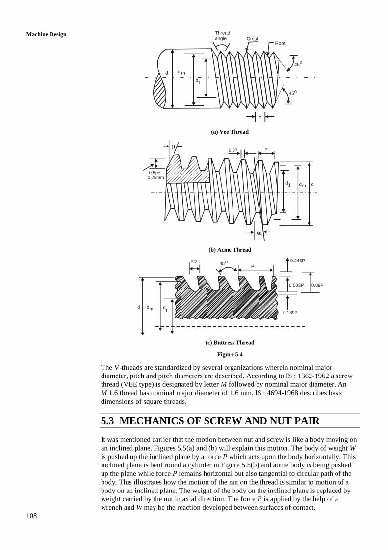
screw and the nut increases. Figure 5.4 shows Vee or triangular, the Acme and the
buttress threads with leading nomenclature.
The major diameter is the largest diameter of the screw thread denoted by d for external
thread and by D for internal thread. Minor diameter (d1 or D1) is the smallest diameter of
the screw. Some times more than one thread may be cut on the screw. These multiple
threads may be easily seen at the end of the screw where more than one thread will
appear to start. Multiple start threads give the advantage that screw can move through a
longer distance in the nut when given one rotation as compared to the screw with a
single thread or start. The distance moved by a screw along its axis when given one
rotation is called the lead. Apparently
lead = number of starts pitch . . . (5.2)
108
Machine Design
d d m
Threadangle Crest
Root
45o
P
Vee Thread
45o
d1
(a) Vee Thread
0.37 P
0.5p+0.25mm
d1 d dm
(b) Acme Thread
P/2
d d dm 1
0.245P
0.503P 0.89P
0.139P
P45o
(C) Buttress thread
(c) Buttress Thread
Figure 5.4
The V-threads are standardized by several organizations wherein nominal major
diameter, pitch and pitch diameters are described. According to IS : 1362-1962 a screw
thread (VEE type) is designated by letter M followed by nominal major diameter. An
M 1.6 thread has nominal major diameter of 1.6 mm. IS : 4694-1968 describes basic
dimensions of square threads.
5.3 MECHANICS OF SCREW AND NUT PAIR
It was mentioned earlier that the motion between nut and screw is like a body moving on
an inclined plane. Figures 5.5(a) and (b) will explain this motion. The body of weight W
is pushed up the inclined plane by a force P which acts upon the body horizontally. This
inclined plane is bent round a cylinder in Figure 5.5(b) and aome body is being pushed
up the plane while force P remains horizontal but also tangential to circular path of the
body. This illustrates how the motion of the nut on the thread is similar to motion of a
body on an inclined plane. The weight of the body on the inclined plane is replaced by
weight carried by the nut in axial direction. The force P is applied by the help of a
wrench and W may be the reaction developed between surfaces of contact.
109
Design of Screws,
Fasteners and Power
Screws
N
WF
P
(a) Inclined Plane
r
W
Thread
Basecylinder
(b) Inclined Plane Wrapped Round a Base Cylinder to Form a Thread
Figure 5.5
This is illustrated in Figures 5.6(a) and (b). Imagine that a lever is pivoted on the axis of
the cylinder and pushes the body of weight W up the incline of helically wrapped plane
on the cylinder. The lever touches the body at a radius r while a force P1 is applied on
the lever at an arm length of L. In the nomenclature we have already defined the outer
diameter of the thread as major diameter, d and the smallest diameter as the diameter of
the cylinder, d1, (also called core diameter). r is 2
dm where dm is the mean diameter of
thread, being mean of d and d1. If P be the force applied by the lever on the body of
weight W, then by taking moments of forces, acting upon the lever, about the axis of the
cylinder.
12
m
P LP
d . . . (5.3)
M
P1
Nut
Coads add upto W
Threads
Wrench
(a)
dm/2
L
P
W
P1
F
N
(b)
Figure 5.6
110
Machine Design
The force P has to overcome the friction as well as cause lifting of the body in vertical
direction. To find the relationship between force P, called effort, and weight of the body,
W, we have to consider the equilibrium of the body on an inclined plane as shown in
Figures 5.7(a) and (b). The free body diagram clearly shows forces along and
perpendicular to the inclined plane.
N
W
P
CosP
SinW
SinPCosWN
(a) A Body being Pushed Up the Inclined Plane with Angle of Inclination a, by a Horizontal Force P
SinPcosWN
CosP
SinW
(b) Free Body Diagram of Body of Weight w
Figure 5.7
The sum of the forces perpendicular to the plane and sum of the forces along the plane
should separately be zero to satisfy the conditions of equilibrium. is taken as
coefficient of friction between the body and the plane, which is same as coefficient of
friction between the nut and screw thread surfaces. = tan where is the angle of
friction.
Summing up the forces perpendicular to the plane.
The normal reaction,
N = W cos + P sin
Hence, force of friction between the surfaces of contact
cos sinF N W P
Summing up the forces parallel to the inclined plane
cos sin cos sin P W W P . . . (i)
Replacing sin
by tancos
sin sin
cos sin sin coscos cos
P P W W
cos cos sin sin sin cos cos sinp P W W . . . (ii)
cos ( ) sin ( )P W
tan ( ) P W . . . (5.4)
If there is no friction, = 0 and effort in such a case is called ideal effort denoted by Pi
where
tan iP W . . . (5.5)
111
Design of Screws,
Fasteners and Power
Screws
Hence the efficiency of an inclined plane with inclination of or the efficiency of a
screw having helix angle is
iP
p
tan
tan ( )
. . . (5.6)
If in a situation as shown in Figure 5.7(a), P is removed, will the body slide down?
Obviously it will depend upon the fact as to how large angle is. If W sin > W cos
the body will slide down under its own weight (Examine (i) and (ii) with P = 0). Same
thing will happen in case of a nut in Figure 5.6 (a), i.e. when effort P1 is removed from
the wrench or wrench is removed, the nut will rotate back under load W. It means the nut
is not self-locking. However, if is reduced it can be seen that at = , the downward
component (along the plane) of weight W, i.e. W sin and friction force (along the
plane) W cos become equal and the body remains just stationary or the nut does not
move down. If < , the body will need a force to act so as to push it down. If this force
is P then
tan ( )P W . . . (5.7)
Naturally screws of > , will not be self locking or in other words they cannot act as
fasteners. If, however, the angle < , an effort P, given by Eq. (5.7) will be required to
unscrew the nut, and such screws can be used as fasteners.
The Eq. (5.6) which defines the efficiency of the screw and that the condition for screw
to be self locking is that can be used to determine the maximum efficiency of a self
locking screw and nut pair.
For self locking condition, the efficiency
tan
tan ( )s
2tan tan (1 tan )
tan 2 2tan
21 tan
2
Since tan2 is always less than 1, ( = tan )
1
2s . . . (5.8)
The screw having efficiency greater than 50% is said to over haul, meaning the load W
will cause the nut to roll down.
5.4 POWER SCREW MECHANICS
In the preceding section the simple case of a square thread was considered. As will be
seen in the text that follows that the square thread is more efficient than the Acme thread
because in the Acme thread the effective coefficient of friction increases, yet for power
screws it is the Acme thread which is used more predominantly. The Acme thread can be
machined more easily than the square thread and more importantly the clearance in the
Acme thread can be adjusted to take care of the wear or machining inaccuracy.
Figure 5.8 shows the nuts in pair with square and the Acme threads and an adjusting
mechanism for the acme thread.
112
Machine Design
1st nut Twonarrow nut
2nd nut
Parton nut
(a) (b)
1st nut 2nd nut
Screw
(c)
Figure 5.8 : (a) A Square thread and Nut (b) An Acme Thread and Two Nuts for Adjusting Clearance
on Both sides of the Thread. Two Narrow nuts Threading on Outside of the nut Push the Two Nuts in
Opposite Direction (c) Adjustment of Clearance on Two Sides of thread
An Acme thread has two inclination. Firstly the plane of the thread is sloping along
angle of helix in the direction of the helix. The plane of the thread also slopes away from
the circumference of the screw, i.e. the circumference of diameter d1, The same is true
for the V-thread. Both types of threads are as shown in Figures 5.4(a) and (b). The effect
of inclination in the radial direction is to increase the normal reaction between the nut
and the screw. This inclination in the radial direction of thread gives a shape of
trapezium of angle 2 as shown in Figure 5.9 and since the motion will occur
perpendicular to the plane of paper; the force of friction will depend upon the normal
reaction.
W
ScrewNut
W
Cos
WN
2
Figure 5.9 : A Nut Moving on a Screw having Acme Thread
For a vertical force W pressing the nut on the thread of screw, the normal reaction is N.
Resolving N in the vertical direction and equating with W
cos orcos
WN W N
and hence the force of friction along the direction of helix is orcos
WN
which can
also be written as W and can be called a modified or effective coefficient of
friction. No doubt you can see that
cos
. . . (5.9)
It is because cos is less than 1. Greater the angle , lesser the cos and hence will
increase with increasing . This is what happens in V-thread. The force of friction
between nut and thread in V-threads is greater than in Acme thread. The P-W
113
Design of Screws,
Fasteners and Power
Screws
relationship given by Eq. (5.4) stands valid for square thread and can be modified for
Acme thread by replacing by where
1tan
tan ( ) P W . . . (5.10)
Efficiency of the Acme thread will be
tan
tan ( )
. . . (5.11)
A word about the horizontal component of N, which is N sin will be in order.
Remember we are talking about the thread round the circumference of the screw. There
is other side of the screw on right of Figure 5.9 and N sin there will be acting to the
right. Thus the horizontal components of N are balanced.
The force P which acts as tangent to the mean circle of diameter d, between the outer
circle of diameter d and inner circle of diameter d1, i.e. at radius 1
2 4
md d d will cause
a moment
2
mt
PdM
or tan ( )2
mt
dM W . . . (5.12)
Here is the effective angle of friction which could be 1tan if the square thread
is on the screw. Apparently the torque in Eq. (5.12) will twist the cylinder of screw and
cause shearing stress in it. The cylinder is acted upon by an axial compression also. The
axial compressive force causes compressive stress at any point in the section.
Example 5.1
A square threaded screw is required to work against an axial force of 6.0 kN and
has following dimensions.
Major diameter d = 32 mm; pitch p = 4 mm with single start, = 0.08. Axial force
rotates with the screw.
Calculate :
(a) Torque required when screw moves against the load.
(b) Torque required when screw moves in the same direction as the load.
(c) Efficiency of the screw.
Solution
Remember the relationship between p, d and d1 which has been shown in
Figure 5.1.
1p d d
But 11or 2
2m m
d dd d d d
2 ( )mp d d
or 2
m
pd d
Using d = 32 mm and p = 4 mm
32 2 30 mmmd . . . (i)
The angle of helix is related to the circumference of mean circle and the pitch
from description of Section 5.2.
114
Machine Design
4
tan 0.04230m
p
d
. . . (ii)
o2.4 . . . (iii)
and tan 0.08 . . . (iv)
otan 4.57
From Eq. (5.12) torque required to move screw against load
tan ( )2
mt
dM W
30
6 tan (2.4 4.57) 6 0.12225 15 Nm2
= 11 Nm . . . (v)
When screw moves in the same direction, is a case in which the body moves down
the inclined plane. In this case the fore P to push down is given by Eq. 5.7.
Hence, the torque
tan ( )2 2
m mt
d dM P W
30
6 tan (4.57 2.4) 6 0.038 15 Nm2
= 3.42 Nm . . . (vi)
From Eq. (4.6), efficiency
tan 0.042
0.344tan ( ) 0.12225
or = 34.4% . . . (vii)
Example 5.2
If in the Example 5.1, the screw has the Acme thread with thread angle 2 = 29o
instead of square thread, calculate the same quantities.
Solution
There is no difference in calculation for square and the Acme thread except that in
case of the Acme thread the coefficient of friction is modified and effective
coefficient of friction is given by Eq. (5.9).
0.08 0.08
0.0826cos 29cos 0.968
2
o4.724
From Figure 5.2(b) for the Acme thread note that
0.125 mm2
m
pd d
32 2 0.125
or 29.875 mmmd . . . (i)
4
tan 0.042629.875m
p
d
o2.44
115
Design of Screws,
Fasteners and Power
Screws
tan ( )2
t m
WM d
3.0 29.875 tan (2.44 4.724) 89.625 0.126 kNmm
or 11.265 NmtM . . . (ii)
tan tan 2.44 0.0426
tan ( ) tan (2.44 4.724) 0.126
or 33.8% . . . (iii)
When the screw moves in the same direction as the load, the torque
tan ( )2
mt
W dM
6 29.875
tan (4.724 2.44) kNmm2
or 3.58 NmtM . . . (iv)
Comparing the results of Examples 5.1 and 5.2 we can see that the screws have
got same major diameter and pitch and for this reason their helix angles are
different. Coefficients of friction are inherently different. But the torque on the
screw increases by 2.41% and efficiency decreases by 1.744%.
SAQ 1
(a) Distinguish between square and the Acme threads, the Acme threads and
the V-threads. Also mention relations for pitch, various diameters.
(b) What do you understand by multi-start thread? Define lead and the pitch
and give relation between them. If two threads are having same pitch but
one is single start and other is three starts, which one will advance more and
how much if screw is turned through one full rotation in the nut.
(c) What reason you can put forth for preferring the Acme threads to square
threads?
(d) A horizontally fixed nut carries a vertical screw of square thread whose
mean diameter is 50 mm, and the pitch is10 mm. On the top of the screw a
circular disc 100 N weight and 100 mm diameter is fixed and this disc has
radial hole into which a rod of 1.1 m is fixed such that 1 m length is out of
the disc. If at the end of this rod an effort of 280 N is required to lift a load
placed on the disc, calculate the load. The coefficient of friction between
the threads of the screw and nut is 0.1.
5.5 APPLICATION OF POWER SCREW
Power screws are used in machines and equipment for lifting loads, applying pull forces,
translating loaded machine parts and tools and for positioning devices. It can work in
two modes, either with a fixed nut and moving screw or with a fixed screw and moving
nut. The rotary motion can be given to any of the nuts or screw. The simplest device one
can think of is a screw jack, often used for lifting heavy loads. The load can be placed on
top of a platform (like disc as described in SAQ 1(d)), and with fixed nut the screw may
be rotated with the help of a lever. However, the load will rotate with the screw. The
alternative method would be to rotate the screw supported in vertical direction and
obstruct the screw to rotate with the nut. The two alternatives are shown in Figure 5.10.
116
Machine Design
The lead screw of a lathe machine, which moves the tool carriage, is another example of
power screw in which the screw rotates in a nut and screw is supported like a shaft
between two bearings. The thrust is caused on the nut, which is integral part of the tool
carriage. The nut moves along the length of the screw taking the carriage. The reaction
of the thrust bears on the supports of the screw. The screw can be used for accurate
positioning of the carriage if it is rotated by a separate stepper motor. The screw in
transferring of force can also be used in hand operated punching machines, as a lifter of
dam gate or as a presser of masses.
If there is a support like a collar, shown in Figure 5.10(a) on the top of which the load is
placed so that it does not rotate, then the applied torque has to be equal to the sum of the
torque required to rotate the screw in the nut and the friction torque between the surfaces
of the collar and load platform. The friction torque between the supporting bearing
surface and stationary surface may be reduced by lubrication or by providing rolling
bearing as showing in Figure 5.10(b). In any given situation the torque at bearing surface
will have to be calculated.
W/2W/2
Nut (Fixed)
W/2W/2
L
cd
(a)
W
Platform
Bearing
Nut Rotating
Handle
W/2 W/2
Load
(b)
Figure 5.10
If the collar surface is like a flat disc of outer and inner diameters of do and di then the
friction torque is given by
117
Design of Screws,
Fasteners and Power
Screws
3 3
3 3
2 2 2 2
2 2 2
3 3 ( )
2 2
o i
c o itf c
o io i
d d
W d dM W
d dd d
. . . (5.13)
The Eq. (5.13) has not been derived here. In the above equation c is the coefficient of
friction between the collar and the platform or between bearing surfaces. Hence M tf can
also be writer as c Wrf where rf is the radius of an imaginary circle. Along the tangent of
this circle the force of friction e W is assumed to act. An approximate value of
4
o if
d dr
can also be used. Incidentally this value of rf may be true for unlubricated
surface which is not a reality.
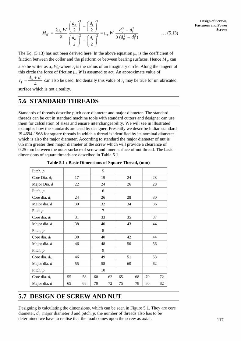
5.6 STANDARD THREADS
Standards of threads describe pitch core diameter and major diameter. The standard
threads can be cut in standard machine tools with standard cutters and designer can use
them for calculation of sizes and ensure interchangeability. We will see in illustrated
examples how the standards are used by designer. Presently we describe Indian standard
IS 4694-1968 for square threads in which a thread is identified by its nominal diameter
which is also the major diameter. According to standard the major diameter of nut is
0.5 mm greater then major diameter of the screw which will provide a clearance of
0.25 mm between the outer surface of screw and inner surface of nut thread. The basic
dimensions of square threads are described in Table 5.1.
Table 5.1 : Basic Dimensions of Square Thread, (mm)
Pitch, p 5
Core Dia. d1 17 19 24 23
Major Dia. d 22 24 26 28
Pitch, p 6
Core dia. d1 24 26 28 30
Major dia. d 30 32 34 36
Pitch p 7
Core dia. d1 31 33 35 37
Major dia. d 38 40 43 44
Pitch, p 8
Core dia. d1 38 40 42 44
Major dia. d 46 48 50 56
Pitch, p 9
Core dia. d1, 46 49 51 53
Major dia. d 55 58 60 62
Pitch, p 10
Core dia. d1 55 58 60 62 65 68 70 72
Major dia. d 65 68 70 72 75 78 80 82
5.7 DESIGN OF SCREW AND NUT
Designing is calculating the dimensions, which can be seen in Figure 5.1. They are core
diameter, di, major diameter d and pitch, p. the number of threads also has to be
determined we have to realise that the load comes upon the screw as axial.
118
Machine Design
Compression causing compressive stress, which is uniformly distributed over circular
cross section of diameter, d1. As the screw rotates, in the nut it is subjected to a torque
given by or tan ( )2 2
m md dP W . This torque will cause shearing stress, which will
be maximum on the surface or at radius of 1
2
d. The transfer of axial load between the
screw thread and nut occurs through surface of thread. The pressure is to be kept within
permissible limits, which normally is such that squeezing of oil film between contact
surface should not occur. Further the thread and the cylindrical surface of the cylinder
may tend to shear off under the load acting on the thread. Lasting we must realize that
the axial load on screw makes the screw to act like a column. This column is not allowed
to buckle. We will consider each of the above modes of failure to establish equations for
calculating dimension.
Direct Stress
The axial load (force) is W, compressive in nature and the area which carries the
force is the core cross section of diameter di. Hence, compressive stress,
21
4W
d
. We will see that this direct compressive stress combines with shearing
stress to give principal and maximum shearing stresses. The resulting equations
cannot be solved for d1, hence the expression for is used to calculate d1 from
given permissible compressive stress. To account for other stresses, which we will
see in next section, the magnitude of the compressive stress is increased by 30%.
Hence 21
1.3
4
W
d
. . . (5.14)
As an example if W = 50 kN and permissible compressive stress is 80 MPa, then
3
2 31
4 1.3 50 101.0345 10
80d
By the helps of Table 5.2 you can see that nearest standard value value of d1 is
33 mm with p = 7 mm and d = 40 mm. This apparently give all the information we
require for a screw but we have to check for safety against other stresses.
Maximum Shearing Stress
We have already seen that torque tan ( )2
mt
dM W is required to rotate the
screw to cause it to move against force W or to lift weight W. the torque will cause
shearing stress in addition to direct compressive stress as stated earlier. The
shearing stress at any point on surface of core
31
16 tM
d
The state of stress at any point on the surface of core of the screw will be
compressive or a direct stress and a shearing stress as shown in Figure 5.11.
Figure 5.11 : State of Stress at any Point on Core Surface of Dia d1
119
Design of Screws,
Fasteners and Power
Screws
The maximum principal stress is given by
22
12 2
p
This stress is not of much significance because it is reduced from higher
magnitude or if it becomes tensile, to a magnitude which is still not much.
However maximum shearing stress is significant.
22
max2
2 2
2 31 1
164
2
tMW
d d
or 22
max 4 61 1
16
64
tMW
d d
. . . (5.15)
The permissible shearing stress will be known but solving Eq. (5.15) will be too
difficult as you can see that it contains fourth and sixth power of d1 and Mt is also
the function of dm (or d1 and d). Therefore it is recommended to calculate d1 from
Eq. (5.14) and using this value of d1, calculate max. Then you have to see that the
calculated value of max is less than permissible value of shearing stress.
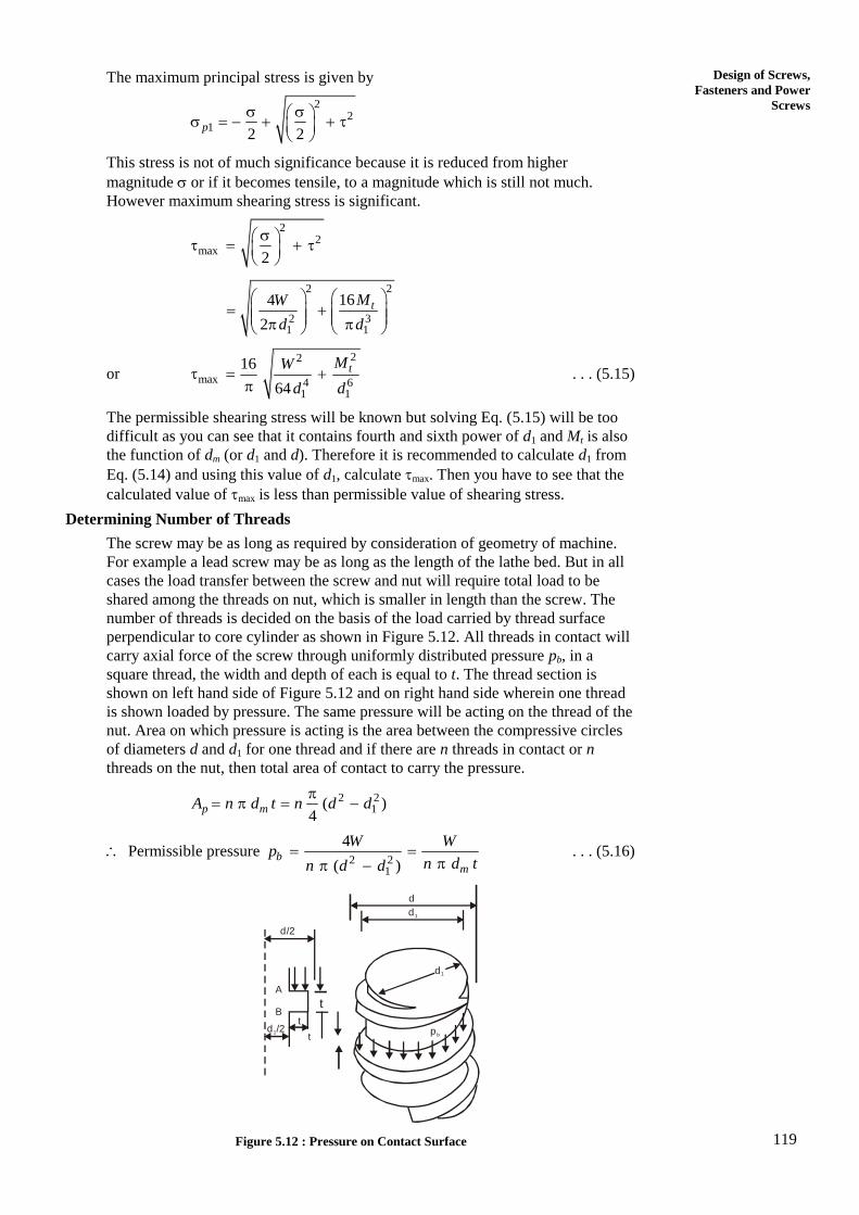
Determining Number of Threads
The screw may be as long as required by consideration of geometry of machine.
For example a lead screw may be as long as the length of the lathe bed. But in all
cases the load transfer between the screw and nut will require total load to be
shared among the threads on nut, which is smaller in length than the screw. The
number of threads is decided on the basis of the load carried by thread surface
perpendicular to core cylinder as shown in Figure 5.12. All threads in contact will
carry axial force of the screw through uniformly distributed pressure pb, in a
square thread, the width and depth of each is equal to t. The thread section is
shown on left hand side of Figure 5.12 and on right hand side wherein one thread
is shown loaded by pressure. The same pressure will be acting on the thread of the
nut. Area on which pressure is acting is the area between the compressive circles
of diameters d and d1 for one thread and if there are n threads in contact or n
threads on the nut, then total area of contact to carry the pressure.
2 21( )
4
p mA n d t n d d
Permissible pressure 2 2
1
4
( )b
m
W Wp
n d tn d d
. . . (5.16)
d
d/2
d1
t
tA
B
d /21
tp b
d1
Figure 5.12 : Pressure on Contact Surface
120
Machine Design
This equation can be used for a check if the pressure between the threads of the
nut and screw is within the permissible limit or it can be used to calculate the
number of threads, n, in contact.
Shearing of Threads from the Core Cylinder
Because of the force W, acting as uniformly distributed pressure as shown in
Figure 5.12 thread may have a tendency to shear. The area over which shear effect
will occur is shown shaded in Figure 5.13. The thread is shown in broken lines.
This area apparently is a strip of width, t, on the cylinder of diameter d1. Hence the
area
1cA d t
With shearing stress , which will be created at the bottom of n thread of screw,
screw1
W
n d t
. . . (5.17)
d 1
t
p b
d 1
d
Figure 5.13 : The Area at the Bottom of a Thread in Screw
You must realise that the threads on the inside of the nut will also be similarly
subjected to shearing stress at their bottom. Hence, in nut
nut
W
n d t
. . . (5.18)
Normally, the screw and nut are not made in the same material. While screw is
made in steel the preferred material for nut is either cast iron or bronze. The
permissible value of shearing stress for nut material may be less and in that case
Eq. (5.18) must be used to calculate n.
The height of the nut is simply the product if n and p, i.e.
h = np . . . (5.19)
You must realise that the nut is threaded all along its length.
The various screw-nut material combinations are described in Table 5.2.
Table 5.2 : Screw-Nut Material Combination and Safe Bearing Pressure
Application Material Safe Bearing
Pressure
(MPa)
Rubbing Velocity
at Mean Diameter
m/min Screw Nut
Hand Press Steel
Steel
Bronze
C.I
17.5-24.5
12.5-17.5
Well lubricated
Low Velocity
Screw Jack Steel
Steel
C.I
Bronze
12.5-17.5
10.5-17.5
Velocity < 2.5
Velocity < 3.0
Hoisting Machine Steel
Steel
C.I
Bronze
4.0-7.0
35.0-100.0
6-12
6-12
Lead Screw Steel Bronze 10.5-17.0 > 15.0
121
Design of Screws,
Fasteners and Power
Screws
Example 5.3
A screw press is required to exert a force of 50 kN when applied torque is
560 Nm. The unsupported length of the screw is 450 mm and a thrust bearing of
hardened steel on cast iron is provided at the power end.
The permissible stresses in the steel screw are :
Tension and compression – 85 MPa, Shear – 55 MPa,
The permissible bearing pressure is 13.5 MPa for steel screw and C.I nut
The permissible shearing stress in the CI is 20 MPa
The yield strength of steel of screw, Y = 260 MPa
The coefficient of friction in screw and nut is 0.15
Determine the dimensions of screw and nut, and efficiency.
Solution
Step 1
Determine diameter d1, d, p, to define the thread
Eq. (5.14), will be used to estimate d1,
21
1.3
4
W
d
Use W = 50,000 N, = 85 N/mm2
21
4 1.3 50,000973.54
85d
1 31.2 mmd
Look in the Table 5.1, close to 31.2 mm the core diameter is 33 mm with
pitch p = 7 mm. However, you may also use following rule : between
d1 = 30 and d1 = 40 mm, p = 0.2 d1.
We choose to use Table 4.1.
So 1 33 mm, 40 mm, 7 mmd d p . . . (i)
1 33 3.5 36.5 mm2
m
d pd
Angle of helix, 1 1 17tan tan tan 0.061
36.5m
p
d
o3.5 . . . (ii)
1tan 0.15, tan 0.15
o8.53 . . . (iii)
Efficiency of screw, tan tan 3.5 0.061
tan ( ) tan (3.5 8.53) 0.213
28.6% . . . (iv)
Number of threads in contact, i.e. threads in nut and height of nut.
122
Machine Design
Use Eq. (5.18), put 2nut3.5 mm, 20 N/mm
2
pt
nut
W
n d t
50,000
2040 3.5n
n = 5.684 say 6
This has to be checked for bearing pressure, pb = 13.5 N/mm2
Use Eq. (5.16)
2 2
1
4
( )b
Wp
n d d
2 2
4 50,0009.23 say 10
13.5 (40 33 )n
This n is greater than the earlier calculated 6. Hence n = 10 is chosen.
Check for maximum shearing stress
tan ( )2
mt
dM W
Use 1 40 3336.5 mm
2 2m
d dd
436.550,000 tan (3.5 8.53) 19.4 10 Nmm
2tM
4 4
3 3 41
16 16 19.4 10 98.8 10
(33) 3.594 10
tM
d
or = 27.4 N/mm2
Also note 2
2 21
4 4 50,00058.5 N/mm
(33)
W
d
22
max2
855.56 750.76 1606.32
2max 40.1 N/mm
The permissible shearing stress is 55 N/mm2.
Hence screw in safe against shearing.
Figure 5.14
123
Design of Screws,
Fasteners and Power
Screws
Example 5.4
Design a screw jack to lift a load of 100 kN through a height of 300 mm. Assume
u = 400 MPa, u = 200 MPa, Y = 300 MPa, pb = 10 MPa. The outer diameter of
bearing surface is 1.6 d1 and inner diameter of bearing surface is 0.8 d1.
Coefficient of friction between collar on screw and C.I is 0.2. Coefficient of
friction between steel screw and bronze nut is 0.15. Take a factor of safety of 5 for
screw and nut but take a factor of safety of 4 for operating lever.
Solution
The screw jack to be designed is shown in Figures 5.15(a) and (b) shows the
details of the cup on which the load W is to be carried.
Figure 5.14 () Screw jack assembled
ro
ri
WL
Cupd2
h
Ha
4d
5d
5d
Body of jack
Screw
d
D1
d1
S
D2
Nut
arm
dp
e
Figure 5.15 : (a) Screw Jack Assembled; and (b) The Load Cup
The overall design of screw jack comprises designing of
(a) Screw,
(b) Nut,
(c) Arm,
(d) Cup, and
(e) Body of the jack.
Screw
Screw becomes the central part. The other parts will be dependent upon the
screw. The screw design will decide core diameter d1, major diameter d and
pitch, p. Hence screw design will consist of calculating d1, d and p and
checking for maximum shearing stress and buckling of the screw.
Assume square thread
Use Eq. (5.14) with W = 100,000 N, 240080 N/mm
5
(a)
(b)
124
Machine Design
21
1.3
4
W
d
11
22
1
5.2 100,000(2069)
80d
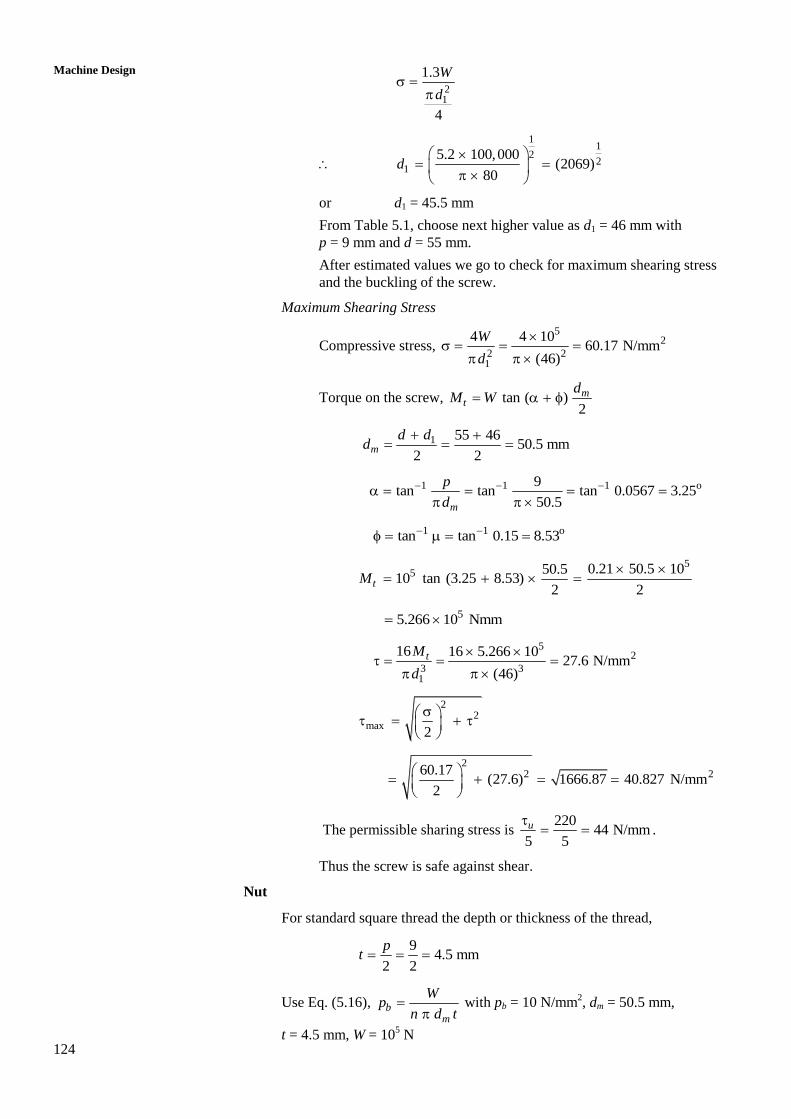
or d1 = 45.5 mm
From Table 5.1, choose next higher value as d1 = 46 mm with
p = 9 mm and d = 55 mm.
After estimated values we go to check for maximum shearing stress
and the buckling of the screw.
Maximum Shearing Stress
Compressive stress, 5
2
2 21
4 4 1060.17 N/mm
(46)
W
d
Torque on the screw, tan ( )2
mt
dM W
1 55 4650.5 mm
2 2m
d dd
1 1 1 o9tan tan tan 0.0567 3.25
50.5m
p
d
1 1 otan tan 0.15 8.53
5
5 0.21 50.5 1050.510 tan (3.25 8.53)
2 2tM
55.266 10 Nmm
5
2
3 31
16 16 5.266 1027.6 N/mm
(46)
tM
d
22
max2
22 260.17
(27.6) 1666.87 40.827 N/mm2
The permissible sharing stress is 220
44 N/mm5 5
u .
Thus the screw is safe against shear.
Nut
For standard square thread the depth or thickness of the thread,
9
4.5 mm2 2
pt
Use Eq. (5.16), bm
Wp
n d t
with pb = 10 N/mm
2, dm = 50.5 mm,
t = 4.5 mm, W = 105 N
125
Design of Screws,
Fasteners and Power
Screws
51014
10 50.5 4.5n
Normally n >10 is not preferred. So we can go for higher d1, d and p. Next
standard values will be d1 = 49 mm, d = 58 mm, p = 9 mm.
Hence, 58 49 107
53.5 mm, 4.5 mm2 2 2
m
pd t
510
13.210 53.5 4.5
n
Since this is also greater than 10, we can go for next higher value of
d1 = 51 mm with d = 60 mm and p = 9 mm.
So that 51 60 111
55.5 mm2 2
md
which will also not satisfy the condition.
The last choice in the table with same p is d1 = 53 mm and d = 62 mm.
So that 53 62 115
57.5 mm2 2
md
which result in n = 12.3 mm.
Still better solution is to go for next series with p = 10 mm.
With d1 = 55, d = 65 mm, and 120
602
md ; t = 5 mm
510
10.610 60 5
n
Which is very close to 10, hence can be accepted.
So the solution changes to d1 = 55 mm, d = 65 mm, p = 10 mm. You need
not check these dimensions because they are larger than the safe ones.
(It is important that the reader understands the reiterative nature of design
and how the help from standards is derived. The iterations have been done
to emphasize that the exercise in design should not be treated as a problem
in strength of materials. In design the problem serves to bring practicability
in focus.
The length of the nut, H = np = 10.6 10 = 106 mm.
Outside Diameter of Nut; see Figure 5.1(b) and Figure 5.9.
The nut is in tension. The section to bear tensile stress is
2 20( )
4D D
D = d + 0.5 mm = 65 + 0.5 = 65.5 mm
Bronze is not as strong as steel. Silicon bronze (Cu = 95%, Si = 4%,
Mn = 1%) is quite good for making nut. This material is available in
wrought condition with u = 330 MPa. If factor of safety of 5 is used, then
permissible tensile stress is 233066 N/mm
5 .
5
2 2 2 20 0
4 10466
( ) ( 655 )t
W
D D D
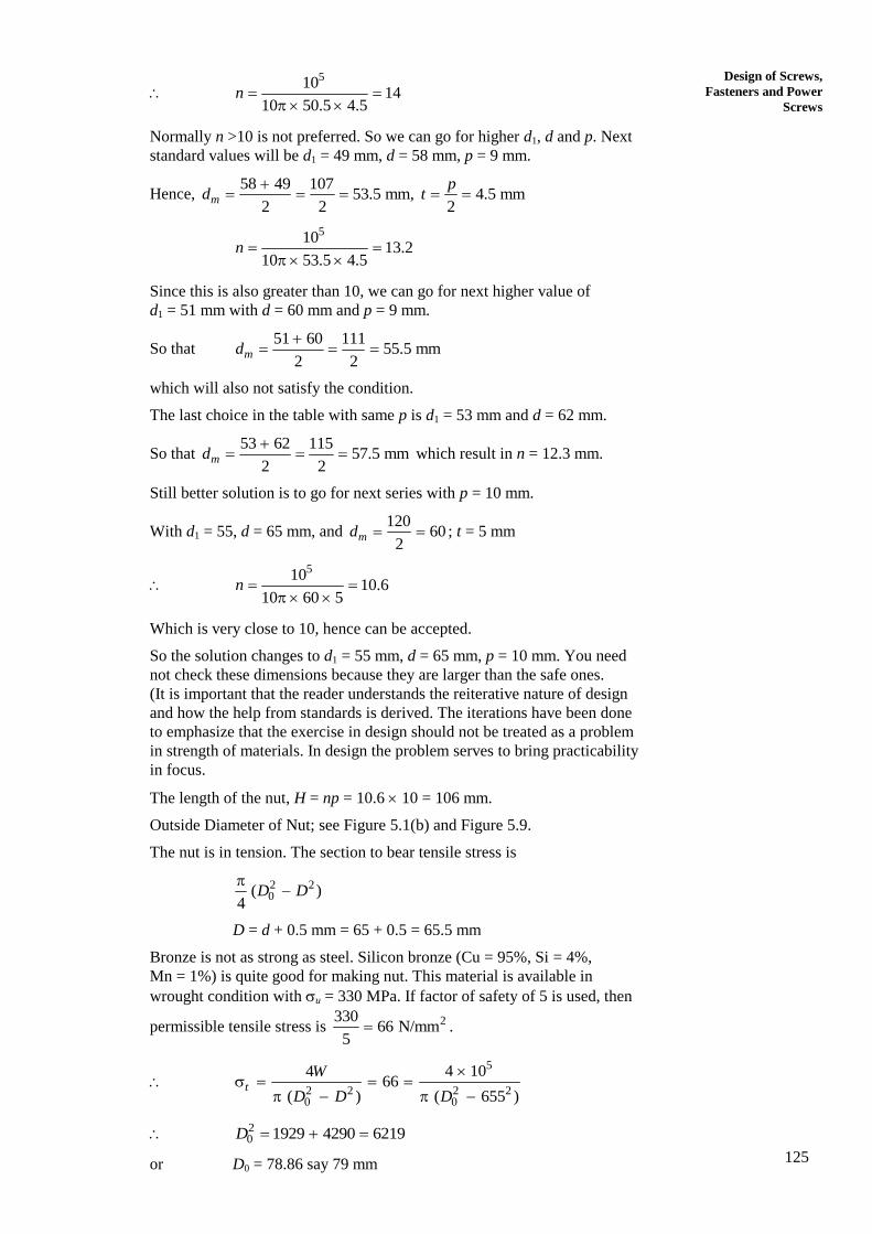
20 1929 4290 6219D
or D0 = 78.86 say 79 mm
126
Machine Design
To fit the nut in position in the body of jack, a collar is provided at the top
(see Figure 5.15(a)).
The thickness of the collar = 0.5 D = 0.5 65.5 = 32.72 mm
The outside diameter of the Collar D00 can be found by considering
crushing of collar surface under compressive stress. The area under
compression is 2 200 0( )
4D D
.
The compressive strength of bronze is same as tensile stress, 66 MPa
5
2 2 200 00
4 4 1066
( 79 ) ( 6241)
W
D D
00 1929 6241 8170 90.4 mmD
The nut is shown in Figure 5.16.
90.4
79
65.5
73.28
32.72
Figure 5.16
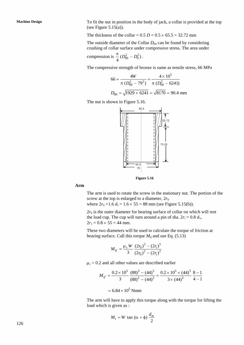
Arm
The arm is used to rotate the screw in the stationary nut. The portion of the
screw at the top is enlarged to a diameter, 2r0
where 2r0 =1.6 d1 = 1.6 55 = 88 mm (see Figure 5.15(b)).
2r0 is the outer diameter for bearing surface of collar on which will rest
the load cup. The cup will turn around a pin of dia. 2ri = 0.8 d1,
2r1 = 0.8 55 = 44 mm.
These two diameters will be used to calculate the torque of friction at
bearing surface. Call this torque Mtf and use Eq. (5.13)
3 3
0
2 20
(2 ) (2 )
3 (2 ) (2 )
c itf
i
W r rM
r r
c = 0.2 and all other values are described earlier
5 3 3 5 3
2 2 2
0.2 10 (88) (44) 0.2 10 (44) 8 1
3 4 1(88) (44) 3 (44)tfM
56.84 10 Nmm
The arm will have to apply this torque along with the torque for lifting the
load which is given as :
tan ( )2
mt
dM W
127
Design of Screws,
Fasteners and Power
Screws
o 1 1 1 o108.53 , 60 mm, tan tan tan 0.05 3
60m
m
pd
d
5 510 30 tan (11.53) 6.12 10 NmmtM
Total torque 5 5(6.84 6.12) 10 13 10 Nmmtf tM M M
A single man can apply 400 N of force but two men can apply 80 N with an
efficiency of 90%. Let’s assume two persons work at the end of the arm, the
length of the arm
513 10
1805.5 mm or 1.805 m0.9 800
L
Actual length will incorporate allowance for grip and insertion in collar so
arm of 2.1 m length will be appropriate.
The torque M will acts as bending moment on the arm with permissible
bending stress as 2400160 N/mm
2.5 . The diameter of arm
115 3332 32 13 10
43.75 mm160
ab
Md
The Cup
The shape of the cup is shown in Figure 5.15(b). It can be made in C1 and
side may incline 30o with vertical. With bottom diameter as 1.2 (2ri), its
height can be decided by the geometry of load to be lifted. Since no
information is given we leave this design only at shape.
The Body of the Jack
Height = Lifting height +length of the nut – length of the collar on the nut +
allowance for bottom plate of 2 mm thickness and head of the bolt
holding plate.
= 300 + 106 – 32.72 + (2 + 4.8) (using a 6 mm bolt)
= 380.1 mm
Thickness, 0.25 0.25 65 16.25 mmd
Thickness of base, 1 0.5 0.5 65 32.5 mmd
Diameter of base, 2 4.0 4 65 260 mmD d
Diameter of base (outside), 3 5 5 65 325 mmD d .
Efficiency
tan 0.0524.5%
tan ( ) 0.204
Listing of Designed Dimensions.
Screw : Square Thread.
Core diameter of screw, d1 = 55 mm
Major diameter of screw, d = 65 mm
Pitch of Thread, p = 10 mm.
128
Machine Design
Nut
Number of threads, n = 10.6
Height of the nut, H = 106 mm
Outside diameter D0 = 79 mm
Diameter of Nut collar, D00 = 90.4 mm
Thickness of collar = 32.72 mm
Arm of the Jack
The length of the arm = 2.1 m
The diameter of the arm = 43.57 mm
The Body of the Jack
Thickness of the body, = 16.25 mm
Thickness of the base, 1 = 32.5 mm
Inside diameter of base, D2 = 260 mm
Outside diameter of base, D3 = 325 mm
Height of the body H1 = 380.1 mm
SAQ 2
(a) Mention industrial applications of screw.
(b) Describe steps involved in designing screw.
(c) Draw the assembled view of screw jack designed in Example 5.4 of
Section 5.9.
(d) For a screw of d1 = 17 mm, p = 5 mm, d = 22 mm subjected to axial
compression of 4000 N, calculate maximum shearing stress and bearing
pressure between threads of screw and nut. Calculate factor of safety in
compression of screw, shearing of screw and bearing pressure if
u = 320 N/mm2, u = 212 N/mm2, maximum pressure = 12 N/mm
2.
Take = 0.12. There are 5 threads in nut.
(e) Acme threaded screw rotating at 60 rpm pulls a broaching cutter through a
job. The tensile force in the screw is supported by a collar whose internal
and external diameters are respectively 60 mm and 90 mm. Coefficient of
friction for all contact surfaces is 0.15 and Acme thread angle is 30o. The
requirement of the tool displacement demands that the pitch of the Acme
thread should be 10 mm and corresponding major screw diameter is 55 mm.
the power consumed by the machine is 0.39 kW, calculate the axial load
exerted upon the tool.
5.8 THREADED FASTENER
Apart from transmitting motion and power the threaded members are also used for
fastening or jointing two elements. The threads used in power screw are square or Acme
while threads used in fastening screws have a vee profile as shown in Figure 5.4(a).
Because of large transverse inclination the effective friction coefficient between the
screw and nut increases by equation cos
where is the basic coefficient of
friction of the pair of screw and nut, is the half of thread angle and is the effective
coefficient of friction. The wedging effect of transverse inclination of the thread surface
129
Design of Screws,
Fasteners and Power
Screws
was explained in Section 5.4. According to IS : 1362-1962 the metric thread has a thread
angle of 60o. The other proportions of thread profile are shown in Figure 5.17. IS : 1362
designates threads by M followed by a figure representing the major diameter, d.
For example a screw or bolt having the major diameter of 2.5 mm will be designated
as M 2.5.
The standard describes the major (also called nominal) diameter of the bolt and nut,
pitch, pitch diameter, minor or core diameter, depth of bolt thread and area resisting load
(Also called stress area). Pitch diameter in case of V-threads corresponds to mean
diameter in square or Acme thread. Figure 5.15 shows pitch diameter as dp. Inequality of
dm and dp is seen from Figure 5.17. Tables 5.3 and 5.4 describes V-thread dimensions
according to IS : 1362.
Nut
Bolt
P/4
H/8
H/2
H0.708H
H/4H/6
o60
1d
dpd
Figure 5.17 : Profiles of Fastener Threads on Screw (Bolt) and Nut
Table 5.3 : Dimensions of V-threads (Coarse)
Designation p
(mm)
d or D
(mm)
dp
(mm)
DC
(mm)
Thread
Depth
(mm)
Stress
Area
(mm2) Nut Bolt
M 0.4 0.1 0.400 0.335 0.292 0.277 0.061 0.074
M 0.8 0.2 0.800 0.670 0.584 0.555 0.123 0.295
M 1 0.25 1.000 0.838 0.729 0.693 0.153 0.460
M 1.4 0.3 1.400 1.205 1.075 1.032 0.184 0.983
M 1.8 0.35 1.800 1.573 1.421 1.371 0.215 1.70
M 2 0.4 2.000 1.740 1.567 1.509 0.245 2.07
M 2.5 0.45 2.500 2.208 2.013 1.948 0.276 2.48
M 3 0.5 3.000 2.675 2.459 2.387 0.307 5.03
M 3.5 0.6 3.500 3.110 2.850 2.764 0.368 6.78
M 4 0.7 4.000 3.545 3.242 3.141 0.429 8.78
M 5 0.8 5.000 4.480 4.134 4.019 0.491 14.20
M6 1 6.000 5.350 4.918 4.773 0.613 20.10
M 8 1.25 8.000 7.188 6.647 6.466 0.767 36.60
M 10 1.5 10.000 9.026 8.876 8.160 0.920 58.30
M 12 1.75 12.000 10.863 10.106 9.858 1.074 84.00
M 14 2 14.000 12.701 11.835 11.564 1.227 115.00
M 16 2 16.000 14.701 13.898 13.545 1.227 157.00
M 18 2.5 18.000 16.376 15.294 14.933 1.534 192
M 20 2.5 20.000 18.376 17.294 16.933 1.534 245
M 24 3 24.000 22.051 20.752 20.320 1.840 353
M 30 3.5 30.000 27.727 26.211 25.706 2.147 561
M 36 4 36.000 33.402 31.670 31.093 2.454 976
M 45 4.5 45.000 42.077 40.129 39.416 2.760 1300
M 52 5 52.000 48.752 46.587 45.795 3.067 1755
M 60 5.5 60.000 56.428 54.046 53.177 3.374 2360
130
Machine Design
Table 5.4 : Dimensions of V-Threads (Fine)
Designation p
(mm)
d or D
(mm)
dp
(mm)
DC
(mm)
Thread
Depth
(mm)
Stress
Area
(mm2)
Nut Screw
M 8 1 1 8.000 7.350 6.918 6.773 0.613 39.2
M 10 1.25 1.25 10.000 9.188 8.647 8.466 0.767 61.6
M 12 1.25 1.25 12.000 11.184 10.647 10.466 0.767 92.1
M 14 1.5 1.5 14.000 13.026 12.376 12.166 0.920 125
M 16 1.5 1.5 16.000 15.026 14.376 14.160 0.920 167
M 18 1.5 1.5 18.000 17.026 16.376 16.160 0.920 216
M 20 1.5 1.5 20.000 19.026 18.376 18.160 0.920 272
M 22 1.5 1.5 22.000 21.026 20.376 20.160 0.920 333
M 24 2 2 24.000 22.701 21.835 24.546 1.227 384
M 27 2 2 27.000 25.701 24.835 24.546 1.227 496
M 30 2 2 30.000 28.701 27.835 27.546 1.227 621
M 33 2 2 33.000 31.701 30.335 30.546 1.227 761
M 36 3 3 36.000 34.051 32.752 32.391 1.840 865
M 39 3 3 39.000 37.051 35.752 35.391 1.840 1028
Wide variety of threaded fasteners are used in engineering practice. These are cylindrical
bars, which are threaded to screw into nuts or internally threaded holes. Figure 5.18
depicts three commonly used fasteners. A bolt has a head at one end of cylindrical body.
The head is hexagonal in shape. The other end of the bolt is threaded. The bolt passes
through slightly larger holes in two parts and is rotated into hexagonal nut, which may sit
on a circular washer. The bolt is rotated into the nut by wrench on bolt head.
As shown in Figure 5.18(a) the two parts are clamped between bolt head and nut.
(a) (b) (c)
Figure 5.18 : Three Types of Threaded Fasteners
A screw is another threaded fasteners with a head and threads on part of its cylindrical
body. However, the threads of the screw are threaded into an internally threaded hole as
shown in Figure 5.18(b). While tightening of joint between two parts by bolt occurs by
rotating either bolt or nut, the screw tightens the parts, through rotation of screw by a
wrench applied at its head. In case of screw the friction occurs between bolt head bottom
and surface of the part in contact, and between threads of screw and hole. In case of bolt
the friction occurs either at bolt head or at the nut. The wrench has to apply torque
against friction between the surface of part and bolt head or nut and in the threads of
contact. Both the bolt and screw are pulled and hence carry tensile force.
A stud is another threaded fastener which is threaded at both ends and does not have a
head. One of its end screws into threaded hole while the other threaded end receives nut.
It is shown in Figure 5.18(c).
The bolts are available as ready to use elements in the market. Depending upon
manufacturing method they are identified as black, semi finished or finished. The head in
131
Design of Screws,
Fasteners and Power
Screws
black bolt is made by hot heading. The bearing surfaces of head or shank are machine
finished and threads are either cut or rolled. In semi finished bolts the head is made by
cold or hot heading. The bearing surfaces of head or shank are machine finished and
threads are either cut or rolled. A finished bolt is obtained by machining a bar of same
section as the head. The threads are cut on a turret lathe or automatic thread cutting
machine.
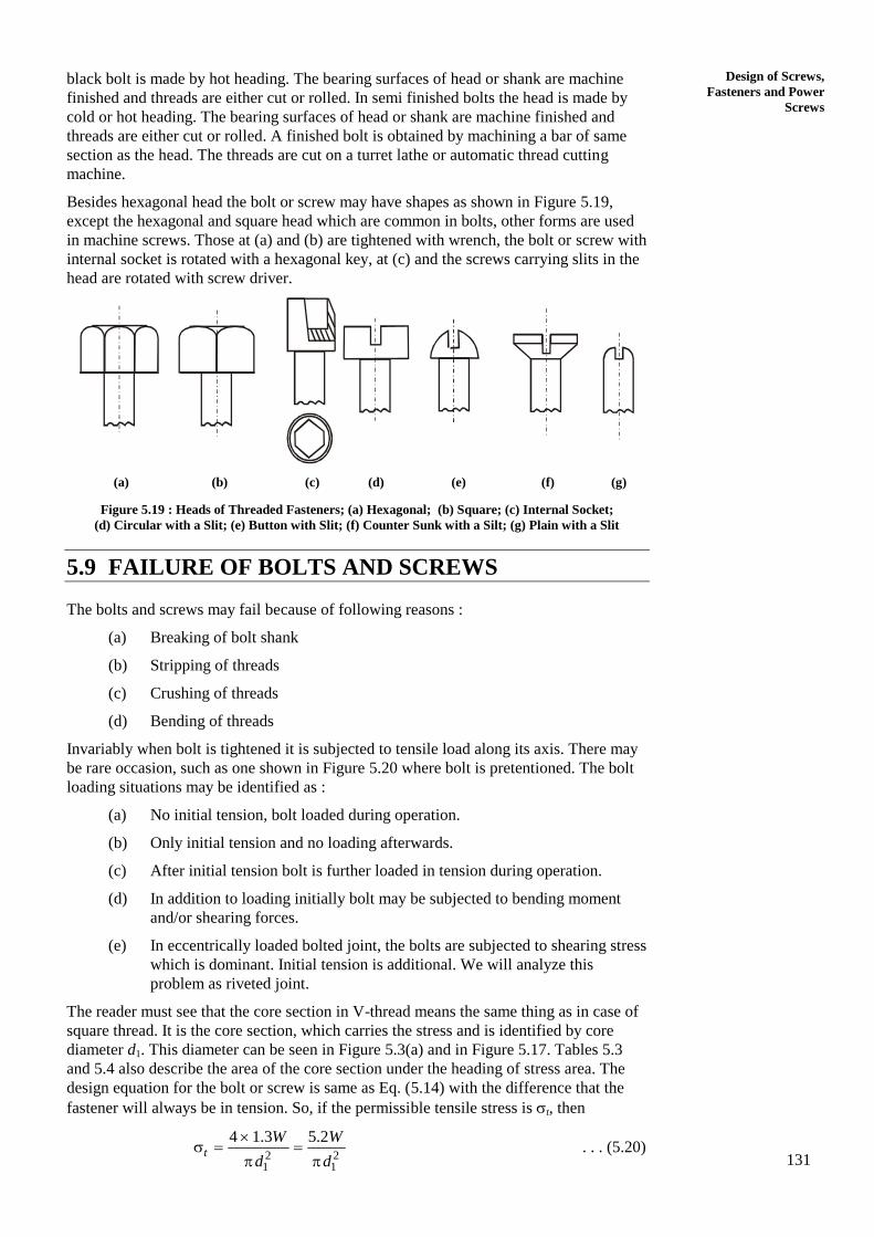
Besides hexagonal head the bolt or screw may have shapes as shown in Figure 5.19,
except the hexagonal and square head which are common in bolts, other forms are used
in machine screws. Those at (a) and (b) are tightened with wrench, the bolt or screw with
internal socket is rotated with a hexagonal key, at (c) and the screws carrying slits in the


![07 Power Screws and Threaded Fasteners [Handout]](https://static.documents.pub/doc/80x56/5695d2d31a28ab9b029bdbf1/07-power-screws-and-threaded-fasteners-handout.jpg)


