1 Unit 6 Magnetic forces 6.1 Introduction. Magnetic field 6.2 Magnetic forces on moving electric charges 6.3 Force on a conductor with current. 6.4 Action of a uniform magnetic field on a flat current-carrying loop. Magnetic moment. Electric engine. 6.5 Hall Effect 6.6 Problems Objectives • Describe the effects of a magnetic field on a moving electric charge. • Calculate the magnetic force acting on a conductor with cur- rent and a loop inside a magnetic field. • Find the magnetic moment of a flat current-carrying loop. • Calculate the torque appearing on a flat current-carrying loop inside a uniform magnetic field. • Explain the Hall Effect. 6.1 Introduction Although the knowledge of magnetic properties of some minerals traces back to the ancient Greece, until 13th century any systematic study of their properties is carried out. In this period, Pierre of Maricourt experiences with magnets knowing two of their properties: • The existence of two magnetic poles rejecting each other if they are equal, and attracting each other if they are different. • The persistence of both poles after breaking the magnet. The use of magnets for the bearings (compass needle) gave name to the poles of a magnet since both poles orient according the north–south terrestrial
Transcript
1
Unit 6
Magnetic forces
61 Introduction Magnetic field
62 Magnetic forces on moving electric
charges
63 Force on a conductor with current
64 Action of a uniform magnetic field on
a flat current-carrying loop Magnetic
moment Electric engine
65 Hall Effect
66 Problems
Objectives
bull Describe the effects of a magnetic field on a moving electric charge
bull Calculate the magnetic force acting on a conductor with cur-rent and a loop inside a magnetic field
bull Find the magnetic moment of a flat current-carrying loop
bull Calculate the torque appearing on a flat current-carrying loop inside a uniform magnetic field
bull Explain the Hall Effect
61 Introduction
Although the knowledge of magnetic properties of some minerals traces back to the ancient Greece until 13th century any systematic study of their properties is carried out In this period Pierre of Maricourt experiences with magnets knowing two of their properties
bull The existence of two magnetic poles rejecting each other if they are equal and attracting each other if they are different
bull The persistence of both poles after breaking the magnet The use of magnets for the bearings (compass needle) gave name to the
poles of a magnet since both poles orient according the northndashsouth terrestrial
2
poles The pole that orients to the north terrestrial pole was called North Pole and a similar situation occurs for the South Pole
This behavior allowed identify the Earth as a magnet and since the poles of the same name reject each other and the ones of different name are attracted a consequence of this fact is that in the north geographic pole there is a magnetic south pole and in the south geographic pole there is a north magnetic pole
In the same way that it happen in electric fields the area of the space where there are magnetic properties is called a magnetic field and an observable consequence of its existence is that it acts on a moving charge as wersquoll see in the following section
62 Magnetic force acting on moving charges Magnetic field
When electrostatic phenomena were studied it was observed that an
electric force EqF
= acts on an electric charge q when an electric field E
exists
However the force on electric charge q doesnrsquot depend only of its posi-
tion but also of its velocity v
Added to electric force another component exists that wersquoll call magnetic force having the following features
bull It only acts if charge is moving bull Itrsquos perpendicular to velocity of the charge bull There is a fixed direction (for each point of space) in such way that when charge is moving in this direction no one force acts on charge bull The magnitude of force is directly related to the value of charge to the value of speed and to the value of a fixed quantity for each point of the space
These features carry us to define the magnetic field B
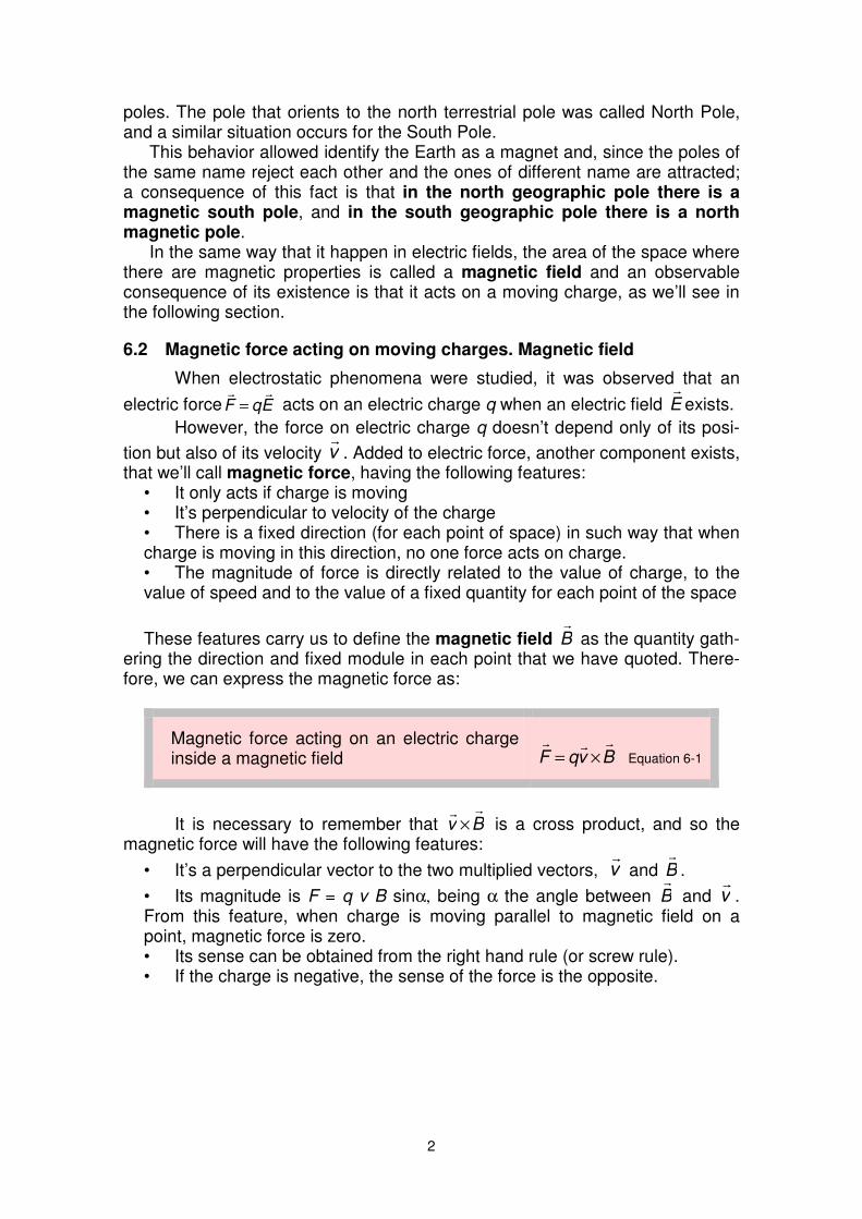
as the quantity gath-ering the direction and fixed module in each point that we have quoted There-fore we can express the magnetic force as
Magnetic force acting on an electric charge inside a magnetic field
BvqF
times=
Equation 6-1
It is necessary to remember that Bv
times is a cross product and so the magnetic force will have the following features
bull Itrsquos a perpendicular vector to the two multiplied vectors v
and B
bull Its magnitude is F = q v B sinα being α the angle between B
and v
From this feature when charge is moving parallel to magnetic field on a point magnetic force is zero bull Its sense can be obtained from the right hand rule (or screw rule) bull If the charge is negative the sense of the force is the opposite
3
oplusq
α
B -q
α
F
F
F
B
v
v
Figure 6-1 Magnetic force is perpendicular to the plane containing the
velocity and the magnetic field vector
The right hand rule or the screw rule has been explained on Unit 0 Itrsquos useful to convert a rotating movement into a line-ar movement determining the corresponding senses Refer to Unit 0 in order to find a more detailed explanation about these rules
v
B
F
The unit of magnetic field B
in the International System is the tesla (T) honoring Croatian scientist Nikola Tesla (1856-1943) From Equation 6-2 it can be stated that there is a magnetic field of one tesla on a point of the space when moving a point charge of one coulomb perpendicularly to magnetic field with a speed of one meter by second on charge acts a force of one newton For the majority of applications 1T is a too big unit as usual magnetic fields are in range of mT being usually used the gauss (G) 1 G = 10-4 T
As an example the terrestrial magnetic field magnitude is roughly 06 G = 60 microT and the magnetic field used in spectroscopy of magnetic nuclear reso-nance is the order of 05 to 30T
As magnetic field is a vector quantity lines being parallel to magnetic field on each point of the space are the magnetic field lines These lines enable us ldquovisualizerdquo the direction of magnetic field at any point of space An example can be seen in Figure 6-2
Magnetic North pole
Magnetic South pole a)
b)
Figure 6-3 a) Lines of the magnetic field in the vicinities of the Earth and b) lines of the magnetic field produced by a circular current
4
There are two characteristics of magnetic field lines
bull The magnetic field lines are perpendicular to magnetic force on each point
bull The magnetic field lines are closed lines since an only type of mag-netic pole (monopole) canrsquot be isolated Until now any one has been able to isolate a north or a south magnetic pole If it would be possi-ble magnetic field lines starting on a monopole and finishing on an-other monopole would exist but as a monopole canrsquot be obtained magnetic field lines are closed lines
If we take in account not only the electrostatic forces but also the mag-
netic forces the total force acting on a charge q with velocity v
inside an electric and a magnetic field is
BvqEqF
times+= Equation 6-2
called Lorentzrsquos Force expressed as a function of E
and B
Movement of point charges inside a uniform magnetic field
Case a) If a point charge q have a parallel velocity v
to the uniform
magnetic field B
the magnetic force acting on charge will be zero so the charge will move with Uniform Linear Motion
Case b) If a point charge has a velocity v
and enters inside a uniform magnetic field B
perpendicular to v
(no electric field exists) a
magnetic force BvqF
times= appears on charge
As this force is perpendicular to movement (no work produces) the speed (modulus of velocity) will be constant and a circular path of radius r will be described by the charge So only a cen-
tripetal acceleration acts on charge r
vaN
2
=
If we call m the mass of charged particle magnetic force and centripetal acceleration can be related through the third
Newtonrsquos law amF
= being possible express the angular frequency of movement as a function of magnetic field electric charge and mass
m
qB
r
v
qB
mvr
r
mvqvB ==== ω
2
A Uniform Circular Motion occurs
1 The perpendicular vectors to plane of paper are represented with symbol when they are
going out from paper to reader and with symbol when they are going in from reader to paper
B
v
r
Fq
Figure 6-4 Charged particle moving in a magnetic field perpendicular to
plane of paper1
5
Case c) When velocity of parti-cle is neither perpendicular nor par-allel to magnetic field velocity can be split in a component in the same direction than magnetic field and another component perpendicular The first one produces a uniform circular motion (as it has been ex-plained) and the second one a uni-form linear motion resulting in a helicoidally path both movements occur at the same time
Selector of speed
In a selector of speed a lot of charged particles with different speed
enter inside a magnetic field The objective is to select an only speed or a narrow range of speeds separating those particles not being in the wished range For this purpose the particles with a wide range of speeds fast slow etc enter in an area with an electrical field and a perpendicular (to the electric field) magnetic field (Figure 6-5) The electric field in the figure pro-duces a force pointing to down whose magnitude qE is not depending on the speed The magnetic field produces a pointing up force depending on the speed qvB In this way the force pointing to up is directly related to the speed and particles with high speed will be deflected to up Particles with low speed will be deflected to down due to the force of electric field Only those particles verifying that qE = qvB will not be deflected and will pass horizontally without deflection along the selector of speed Then this de-vice ldquoclassifiesrdquo the particles according their speed not producing any de-flection on particles with a speed v=EB
qE
qvB
E
- - - - - - -
+ + + + + + +
B
v
B
Ev =
Figure 6-5 Charged particles in a selector of speed They arenrsquot deflected those particles having a speed v = EB
Varying the applied electric field (itrsquos easy to do with only change the difference of potential between plates) charged particles with different speeds can be selected and particles faster or slower can be produced
vN
B
F
VT
Figure 6-4 Negative charged particle with a helicoi-dally movement inside a magnetic field
6
Example 6-1
A proton moves in the direction of the axis x and positive sense in a re-gion where the electric and magnetic field are perpendicular between them
If the electric field is 3 j
kVm sized and the magnetic field 50k
mT sized
Which is the speed of the no deflected protons If the protons are moving slower where will be they deflected to
Solution The no deflected protons are those
bearing an electric force qE equal to the magnetic force qv So
kms601050
1033
3
=sdot
sdot==
minusB
Ev
For lower speeds magnetic force qvB will be lower and therefore they will be deflected to the y positive axis
z
x
y qE
B
v
qvtimesB
E
63 Force acting on an element of current
In previous section we have seen that a force acts on an electric charge moving inside a magnetic field So on a conductor flowed by an electric current inside a magnetic field will also act a magnetic force This force will be the re-sulting force acting on each charge is moving on conductor
Letrsquos consider a conductor flowed by a current I placed inside a
magnetic field B
as on Figure 6- In an interval of time dt the electric charges move along the conductor a
length ℓ
d equal to the product of drift speed by the time
dtvd a
ℓ
=
The electric charge contained
inside the taken piece of conductor (length ℓ
d ) could be computed as the total charge has crossed a cross section of conductor in a time dt and so dq=Idt
Then the elementary force Fd
acting on the element ℓ
d will be
)()()( BdIBvIdtBvdqFd aa
ℓ
times=times=times=
The product ℓ
Id is called an element of current Itrsquos necessary to note that this equation only provides the elementary force acting on an element of current To calculate the force acting on a piece of conductor flowed by an elec-tric current it will be necessary to integrate this expression
Idℓ
B
dF
d =v dtℓ a
I
α
Figure 6-6 Force on an element of current
7
Force acting on a conductor carrying electric charge inside a magnetic field
( ) times=B
A
BdIF
ℓ
ℓ
ℓ
Equation 6-3
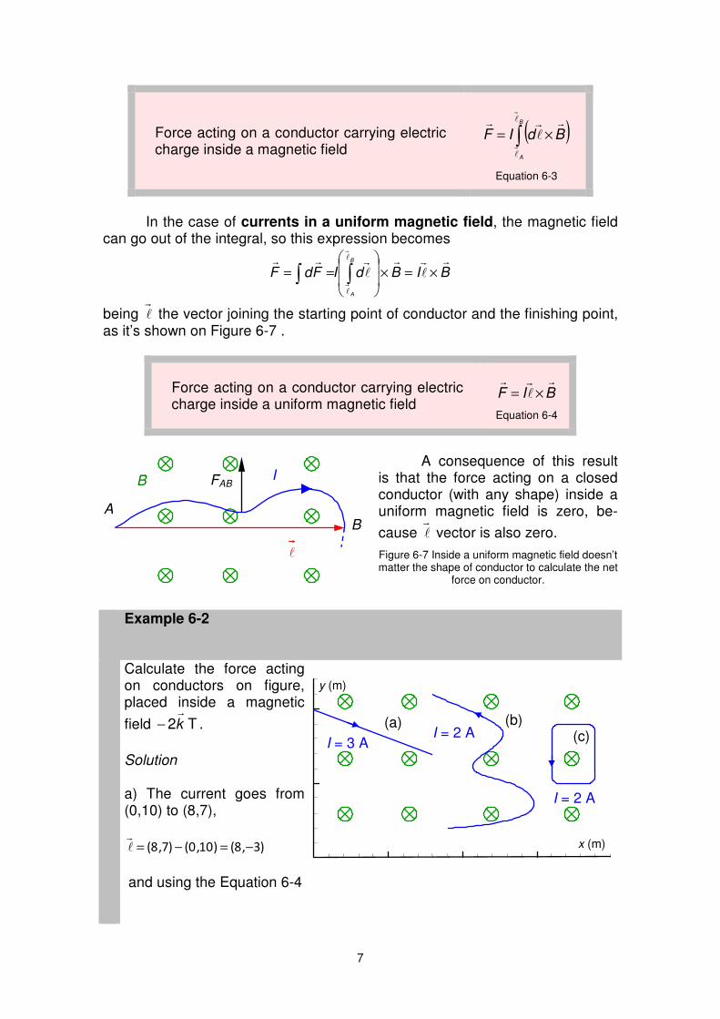
In the case of currents in a uniform magnetic field the magnetic field
can go out of the integral so this expression becomes
BIBdIFdFB
A
ℓ
ℓ ℓ
ℓ
times=times
==
being ℓ
the vector joining the starting point of conductor and the finishing point as itrsquos shown on Figure 6-7
Force acting on a conductor carrying electric charge inside a uniform magnetic field
BIF
ℓ
times=
Equation 6-4
A consequence of this result
is that the force acting on a closed conductor (with any shape) inside a uniform magnetic field is zero be-
cause ℓ
vector is also zero
Figure 6-7 Inside a uniform magnetic field doesnrsquot matter the shape of conductor to calculate the net
force on conductor
Example 6-2
Calculate the force acting on conductors on figure placed inside a magnetic
field T2k
minus
Solution a) The current goes from (010) to (87)
)38()100()78( minus=minus=ℓ
and using the Equation 6-4
I = 3 A
I = 2 A
I = 2 A(a) (b)
(c)
y (m)
x (m)
I
AB
B
FAB
ℓ
8
N4818
200
0383 ji
kji
BIF
ℓ
+=
minus
minus=times=
b) In the same way for any shape of conductor )91()29()118( minus=minus=ℓ
and
N436
200
0912 ji
kji
BIF
ℓ
minusminus=
minus
minus=times=
c) Since itrsquos a closed conductor )00(=ℓ
and 0=F
64 Action of a uniform magnetic field on a flat loop Magnetic moment
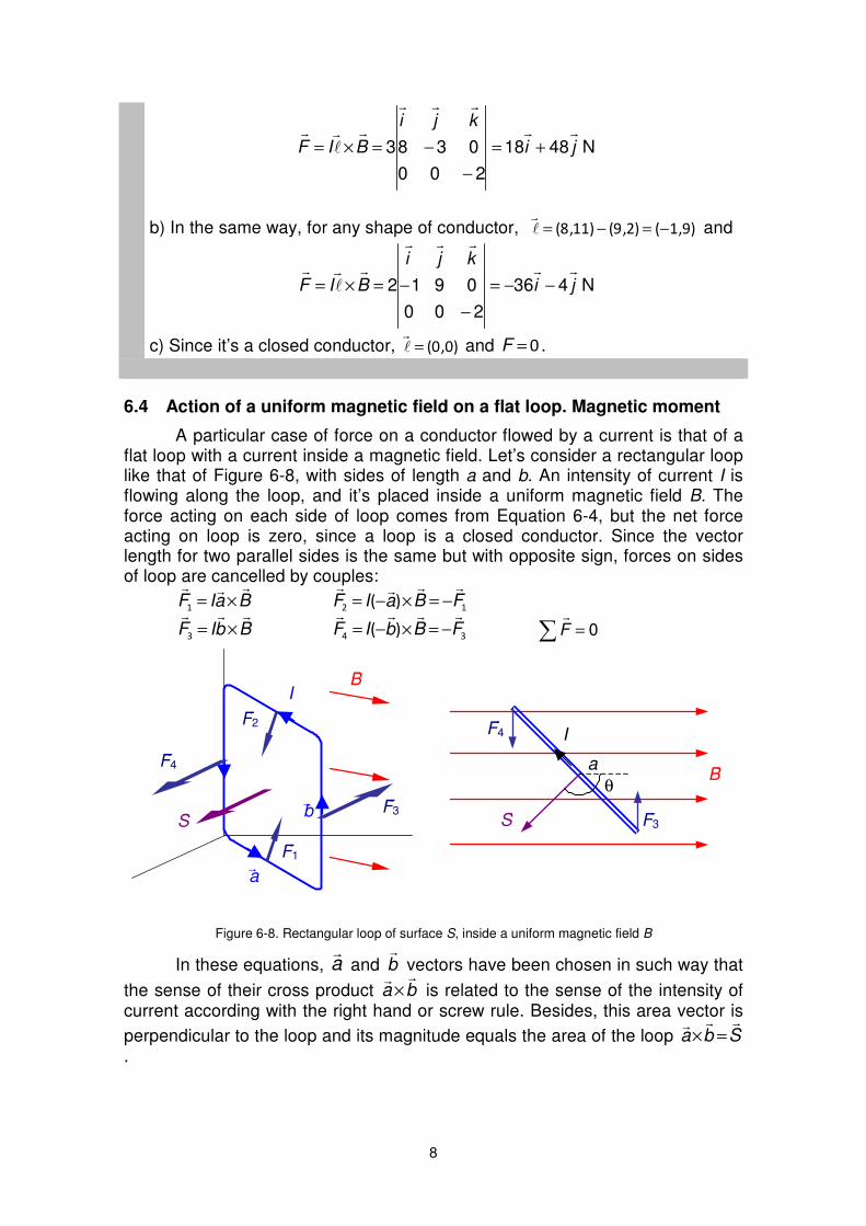
A particular case of force on a conductor flowed by a current is that of a flat loop with a current inside a magnetic field Letrsquos consider a rectangular loop like that of Figure 6-8 with sides of length a and b An intensity of current I is flowing along the loop and itrsquos placed inside a uniform magnetic field B The force acting on each side of loop comes from Equation 6-4 but the net force acting on loop is zero since a loop is a closed conductor Since the vector length for two parallel sides is the same but with opposite sign forces on sides of loop are cancelled by couples
BaIF
times=1 12 )( FBaIF
minus=timesminus=
BbIF
times=3 34
)( FBbIF
minus=timesminus= = 0F
I
B
a
b
F4
F3
F2
F1
S
θ
F4
F3
B
a
S
I
Figure 6-8 Rectangular loop of surface S inside a uniform magnetic field B
In these equations a
and b
vectors have been chosen in such way that
the sense of their cross product ba
times is related to the sense of the intensity of current according with the right hand or screw rule Besides this area vector is
perpendicular to the loop and its magnitude equals the area of the loop Sba
=times
9
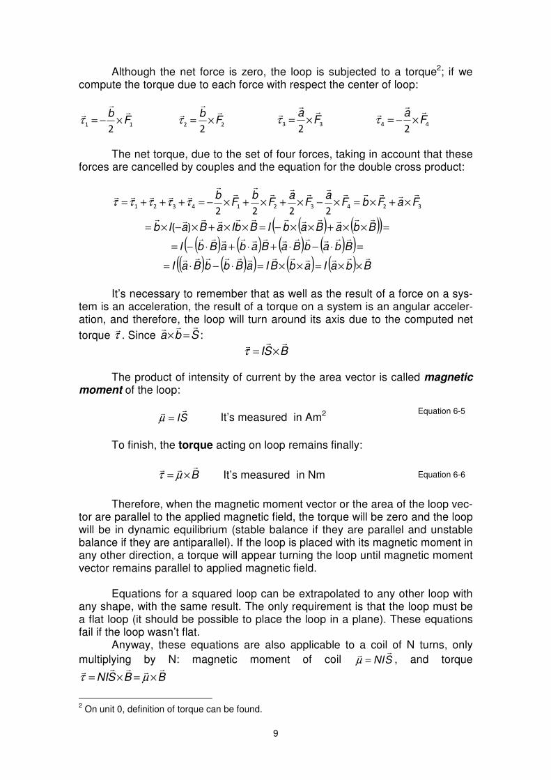
Although the net force is zero the loop is subjected to a torque2 if we compute the torque due to each force with respect the center of loop
112
Fb
timesminus=τ
222
Fb
times=τ
332
Fa
times=τ
442
Fa
timesminus=τ
The net torque due to the set of four forces taking in account that these
forces are cancelled by couples and the equation for the double cross product
Itrsquos necessary to remember that as well as the result of a force on a sys-
tem is an acceleration the result of a torque on a system is an angular acceler-ation and therefore the loop will turn around its axis due to the computed net
torque τ Since Sba
=times
BSI
times=τ The product of intensity of current by the area vector is called magnetic
moment of the loop
SI
=micro Itrsquos measured in Am2 Equation 6-5
To finish the torque acting on loop remains finally
B
times= microτ Itrsquos measured in Nm Equation 6-6
Therefore when the magnetic moment vector or the area of the loop vec-
tor are parallel to the applied magnetic field the torque will be zero and the loop will be in dynamic equilibrium (stable balance if they are parallel and unstable balance if they are antiparallel) If the loop is placed with its magnetic moment in any other direction a torque will appear turning the loop until magnetic moment vector remains parallel to applied magnetic field
Equations for a squared loop can be extrapolated to any other loop with
any shape with the same result The only requirement is that the loop must be a flat loop (it should be possible to place the loop in a plane) These equations fail if the loop wasnrsquot flat
Anyway these equations are also applicable to a coil of N turns only
multiplying by N magnetic moment of coil SNI
=micro and torque
BBSNI
times=times= microτ
2 On unit 0 definition of torque can be found
10
Example 6-3
Along the loop of the figure of sides a b and c flows an intensity I in the shown direction The
loop is placed inside a magnetic field jBB
=
Find a) Magnetic forces on sides of the loop b) Magnetic moment of the loop c) Torque acting on loop Solution
I
ba
c
x
y
z B
a) The force on a conductor of length ℓ
with a current I inside a magnet-
ic field B
is ( )BIF
ℓ
times= Therefore on each side of loop wersquoll have
( ) ( )( ) iIbBjBjckbIBaIFa
=times+minus=times=
( ) iIbBjkIbBFb
minus=times=
( ) 0=timesminus= jjIbBFc
b) Magnetic moment of a loop is defined as SI
=micro As icbicbS
2
1)(
2
1minus=minus=
iIcbicbISI
2
1)(
2
1minus=minus==micro
c) And the torque
kIcbBjBiIcbB
2
1
2
1minus=timesminus=times= microτ
Therefore the torque will try to turn the loop around the OZ axis (in clock-wise sense when itrsquos seen from upside)
Example 6-4
A coil is made up by 100 rectangular loops having 6x4 cm2 of area Itrsquos turned as it ap-pears on picture forming a 37ordm angle with the y axis A 25 A current flows along coil a) Which is the magnetic moment of the coil b) Which is the torque acting on coil when a 2 T magnetic field is applied in the direction of the y axis in positive sense
100 vueltas
I
6 cm
4 cm
y
z
x
α
11
Solution a) The area vector is perpendicular to the plane of coil being its sense according to the screw rule for the intensity of current
2cm)6080(24)3737(cos jijseniSS
minus=minus=
S
37ordmy
x
B
And magnetic moment
24Am)360480()6080(1024250 jijiSNI
minus=minussdotsdot== minusmicro
b) Nm960
020
0360480 k
kji
B
=minus=times= microτ
Therefore the torque will turn the coil in counterclockwise sense
Electric engine
An electric engine is made up by a coil (N loops) able to turn around a fixed axis When a current flows along this coil and a magnetic field is applied to coil a torque acts
|τ| = NISBsenα
Magnetic field can be ap-plied in some different ways but for little engines a perma-nent magnet can be used so magnetic field can be sup-posed as uniform
This torque will produce a turning to align the area vector
parallel to magnetic field (α=0
and τ=0) equilibrium position would be reached after a few os-cillations due to the inertia of coil But when equilibrium position is reached the sense of current on coil is changed through the brushes (two half rings at the end of coil where terminals of battery are gliding) If sense of current is inverted area vector is inverted and magnetic moment
N S
+-
F
F
S
Figure 6-5 Electric engine The magnetic field doesnrsquot change its direction performing the area vector a
whole turn
Clockwise turn
α
m
B
Equilibrium inertial turning
α=0 m
B
α
m
B
Clockwise turning after the brushes have
changed the sense of current
12
remains opposite to magnetic
field (antiparallel) (α=180ordm and
τ=0) In this situation the coil turns a half of turn in order to get magnetic moment parallel to magnetic field When this posi-tion is reached the brushes change the sense of current and the process is repeated in such way that equilibrium is never reached and engine is always turning The inertia of coil ena-bles that the engine donrsquot stop at the exact position where torque is zero
The average torque along a half of turn can be calculated as
1 2
And the transformed power by the engine is
2
From this equation assuming there arenrsquot mechanical losses and using the given definition for contraelectromotive force of a receptor
2
Where k is a constant only depending on the geometry and number of
turns of engine Then contraelectromotive force is linearly related to
B and (angular speed)
65 Hall Effect
Hall Effect is produced when a conductor carries an electric current in a magnetic field As we already know this situation produces a force acting on conductor (section 63) but also produces the Hall Effect Hall Effect is very difficult to detect since it produces differences of potential in the order of μV (10-6 V) and usually itrsquos neglected But in some cases Hall Effect is used to build measurement instruments as happen with instruments to measure mag-netic fields (teslameters) Besides Hall Effect demonstrates that it isnrsquot true that positive charges moving in a sense was completely equivalent to negative charges moving in opposite sense Even this equivalence has been useful when studying direct current Hall Effect leads to different results when positives or negatives charges are supposed Hall Effect is the resulting equilibrium state between a magnetic and an electric field as we are going to study
13
Letrsquos consider a conductor flowed by a cur-rent in a magnetic field perpendicular to current as can be seen on Figure 6-7 In accordance with Equation 6-3 a force per-pendicular to magnetic field and velocity of charg-es appears (FM=qvaB) if we suppose that electrons (negative charge) are moving this force is pointing to down and electrons will be deflected to down when moving So in lower side of conductor wersquoll find a lot of electrons (negative charge) and a lack of them in upper side (positive charge) So an electric field (E) appears on conductor pointing to down (from positive charge to negative charge) and the electrons moving on conductor will suffer an electric force to up (FE=qE) This electric field produces a difference of potential between the upper and the lower side of con-ductor (in the perpendicular direction both to current as to magnetic field) called
Hall voltage (VH) If we suppose electric field as uniform =sdotminus=
C
A
H EadEV ℓ
This voltage is very little (of the order of μV) and can be detected with only very accurate instruments (its polarity is that shown on picture) In the equilibrium state magnetic force and electric force are in equilibrium and the electrons
move without deflection Then itrsquoll be a
H
a
aav
V
v
EBqEBqv ===
As drift speed (va) is related to intensity of current in accordance to equation 32 (I=nqSva) being S the cross section of conductor perpendicular to intensity of current then
aI
nqSV
av
VB H
a
H == Equation 6-7
If we take a piece of conductor n q S and a are constants The intensity of current I can be measured with an ammeter and so magnetic field is directly related to VH Measuring this Hall voltage with an accurate voltmeter magnetic field can be computed and a teslameter can be built But if we consider that charges moving inside conductor are positive charges moving in opposite sense (to right) then the magnetic force also acts to down appearing positive charge on lower side of conductor and negative charge on upper side So polarity of Hall voltage is opposite to that found when negative charges moving on conductor were supposed This difference suppos-ing the charge carriers are positive or negative charges moving in opposite sense will be useful when we study semiconductor materials
VH
va
B
I
A
C
+ -
a
x
y
z
FE
FM
E
Figure 6-6 Hall Effect on a conductor
14
Example 6-5
A piece of silver with 5 cm of width (a) and 05 mm of thickness (e) is placed in a 2 T magnetic field such as it appears on the figure Which is the Hall voltage if 200 A are flowing along conductor You can suppose that sil-ver has 065 free electrons by atom (average value) Data Density of silver 105 gcm3 molar mass of silver 1079 gmole Avo-gadrorsquos number 60221023 atommole
I
a
e
z
x
y
B
Solution
As we are dealing with a conductor negatives charges will move in-
side and the magnetic and electric forces acting on electrons are those drawn on picture
0=+ EM FF
rarr Eq)Bvq(
minus=times
VH
+
-
z
x
y
B
v
FM
FE
EH
In order to apply Equation 6-7 the density of electrons by unit of volume
(n) on silver must be computed It can be done from data of density (ρ) mo-lar mass (mm) of silver and Avogadrorsquos number (Av)
3
28
233
31083
9107
510100226650
)(
)(
)()(650)(m
e
mol
gm
cm
g
mol
atomAv
atom
e
cm
en
m
minusminusminus
sdot=sdotsdotsdot
==
ρ
And from Equation 6-7
VnqS
BaIVH micro131
105010510611083
2001052321928
2
=sdotsdotsdotsdotsdotsdotsdot
sdotsdotsdot==
minusminusminus
minus
15
66 Problems
1 Find the magnetic force acting on a proton moving at 4middot10 6 ms in the posi-tive sense of the X axis inside a 2 T magnetic field in the positive sense of Z axis (Data q(p) = 16middot10-19 C)
Sol N10-128 -12 j=F
sdot
2 Point the initial direction of the deflection of charged particles on picture
Bent Bto up a) Bto right c)
B 45ordm d) Bexiting e) Bto right f)
Negative chargeexiting
Positive charge entering
b)
Sol a) upwards b) perpendicularly to paper going out c) doesnrsquot deflect d) perpendicularly to paper entering e) doesnrsquot deflect f) downwards 3 A bundle of electrons move between the plates of a capacitor with a difference of potential V Between plates there is a uniform magnetic field perpendicular to the electric field If plates of capacitor are separat-ed a distance d calculate the speed of the electrons not deflecting when they move between plates Sol v=VBd 4 A long conductor parallel to the X axis carries a current of 10 A in the posi-tive sense of X axis There is a uniform magnetic field of 2 T in the direction and sense of the Y axis Find the force by unit of length acting on conductor
Sol Nm20k
5 By the segment of conductor in the figure flows a cur-rent I = 2 A from P to Q It exists a magnetic field
T1k=B
Find the total force acting on conductor and
prove that it is the same that if the entire conductor was a straight segment from P to Q
Sol ( ) N1068 2minussdotj-i=F
Y
X
B
B
E
Y
Z
XP
C
Q
I
PC = 3 cm
CQ = 4 cm
16
6 Along conductor AC of figure flows a current of 10 A (itrsquos a part of an electric circuit) being able to glide along two verti-cal rods Compute the necessary uniform magnetic field perpendicular to the plane of the figure in order that the magnetic force on conductor could equilibrate the gravitational force Which should be the sense of magnetic field The length of conductor is 10 cm and its mass 20 g Sol B = 0196 T exiting from paper to reader 7 Along a flat conductor of arbitrary shape flows a current I being the conduc-
tor inside a uniform magnetic field B
perpendicular to the plane of conductor Prove that the total force acting on the piece of conductor going from point a to
another b is BxLI=F
where L
is the vector going from a to b
8 The figure shows one of the rectangular loops of 10 cm by 5 cm of a coil with 20 turns The coil has hinges on side along Z axis and a 01 A current is flowing Which is the torque acting on coil (modulus direction and sense) if it is forming 30ordm regarding the
direction of a uniform magnetic field T05 j=B
Sol Nm1043- -3 k
sdot
9 In order to measure a magnetic field a coil with 200 turns of 14 cm2 of area and forming an angle of 30ordm with the field is used When flowing an intensity of 07 A a torque of 980middot10-6 Nm is measured Com-pute B Sol B = 57middot10-3 T 10 Letrsquos consider the rectangular loop on picture with sides a and b and flowed by an intensity I in the shown sense The loop is in a no uniform magnetic field
kx
aBB
0= Calculate the forces acting on sides 1 and 2
Sol )(2ln0201 jaIBFibIBF
minus==
A C
Z
X
Y30ordm
B
I
SB
Z
Y
30ordm
X
b 1
2a
I
a
Y
2
17
GLOSSARY
Magnetic force on a moving charge Itrsquos the force acting on a charge q when moving with a speed v in a magnetic field B
BvqF
times=
Tesla On a point of the space there is a magnetic field of 1 tesla if a point charge of 1 coulomb moving perpendicularly to the magnetic field with a speed of one meter by second suffer a force of one newton perpendicularly to magnetic field and velocity Force on an element of current Force acting on a conductor of
length ld
flowed by a current I in a magnetic field B
)( BdIFd
ℓ
times=
Magnetic moment of a loop itrsquos the product of the intensity flowing along the loop by the area vector Its sense is that of the area vector that is the resulting to apply the rule of the screw or the right hand to the sense of intensity of current on loop
SIm
= Torque on a loop Itrsquos the cross product between the magnetic mo-ment of the loop and the magnetic field
B
times= microτ
Hall Effect Voltage appearing when an electric current flows along a conductor in a magnetic field This voltage is very little and itrsquos directly related to intensity of current and magnetic field
VH = vaBa Being va the drift speed of charge carriers B the magnetic field and a the width of conductor
2
poles The pole that orients to the north terrestrial pole was called North Pole and a similar situation occurs for the South Pole
This behavior allowed identify the Earth as a magnet and since the poles of the same name reject each other and the ones of different name are attracted a consequence of this fact is that in the north geographic pole there is a magnetic south pole and in the south geographic pole there is a north magnetic pole
In the same way that it happen in electric fields the area of the space where there are magnetic properties is called a magnetic field and an observable consequence of its existence is that it acts on a moving charge as wersquoll see in the following section
62 Magnetic force acting on moving charges Magnetic field
When electrostatic phenomena were studied it was observed that an
electric force EqF
= acts on an electric charge q when an electric field E
exists
However the force on electric charge q doesnrsquot depend only of its posi-
tion but also of its velocity v
Added to electric force another component exists that wersquoll call magnetic force having the following features
bull It only acts if charge is moving bull Itrsquos perpendicular to velocity of the charge bull There is a fixed direction (for each point of space) in such way that when charge is moving in this direction no one force acts on charge bull The magnitude of force is directly related to the value of charge to the value of speed and to the value of a fixed quantity for each point of the space
These features carry us to define the magnetic field B
as the quantity gath-ering the direction and fixed module in each point that we have quoted There-fore we can express the magnetic force as
Magnetic force acting on an electric charge inside a magnetic field
BvqF
times=
Equation 6-1
It is necessary to remember that Bv
times is a cross product and so the magnetic force will have the following features
bull Itrsquos a perpendicular vector to the two multiplied vectors v
and B
bull Its magnitude is F = q v B sinα being α the angle between B
and v
From this feature when charge is moving parallel to magnetic field on a point magnetic force is zero bull Its sense can be obtained from the right hand rule (or screw rule) bull If the charge is negative the sense of the force is the opposite
3
oplusq
α
B -q
α
F
F
F
B
v
v
Figure 6-1 Magnetic force is perpendicular to the plane containing the
velocity and the magnetic field vector
The right hand rule or the screw rule has been explained on Unit 0 Itrsquos useful to convert a rotating movement into a line-ar movement determining the corresponding senses Refer to Unit 0 in order to find a more detailed explanation about these rules
v
B
F
The unit of magnetic field B
in the International System is the tesla (T) honoring Croatian scientist Nikola Tesla (1856-1943) From Equation 6-2 it can be stated that there is a magnetic field of one tesla on a point of the space when moving a point charge of one coulomb perpendicularly to magnetic field with a speed of one meter by second on charge acts a force of one newton For the majority of applications 1T is a too big unit as usual magnetic fields are in range of mT being usually used the gauss (G) 1 G = 10-4 T
As an example the terrestrial magnetic field magnitude is roughly 06 G = 60 microT and the magnetic field used in spectroscopy of magnetic nuclear reso-nance is the order of 05 to 30T
As magnetic field is a vector quantity lines being parallel to magnetic field on each point of the space are the magnetic field lines These lines enable us ldquovisualizerdquo the direction of magnetic field at any point of space An example can be seen in Figure 6-2
Magnetic North pole
Magnetic South pole a)
b)
Figure 6-3 a) Lines of the magnetic field in the vicinities of the Earth and b) lines of the magnetic field produced by a circular current
4
There are two characteristics of magnetic field lines
bull The magnetic field lines are perpendicular to magnetic force on each point
bull The magnetic field lines are closed lines since an only type of mag-netic pole (monopole) canrsquot be isolated Until now any one has been able to isolate a north or a south magnetic pole If it would be possi-ble magnetic field lines starting on a monopole and finishing on an-other monopole would exist but as a monopole canrsquot be obtained magnetic field lines are closed lines
If we take in account not only the electrostatic forces but also the mag-
netic forces the total force acting on a charge q with velocity v
inside an electric and a magnetic field is
BvqEqF
times+= Equation 6-2
called Lorentzrsquos Force expressed as a function of E
and B
Movement of point charges inside a uniform magnetic field
Case a) If a point charge q have a parallel velocity v
to the uniform
magnetic field B
the magnetic force acting on charge will be zero so the charge will move with Uniform Linear Motion
Case b) If a point charge has a velocity v
and enters inside a uniform magnetic field B
perpendicular to v
(no electric field exists) a
magnetic force BvqF
times= appears on charge
As this force is perpendicular to movement (no work produces) the speed (modulus of velocity) will be constant and a circular path of radius r will be described by the charge So only a cen-
tripetal acceleration acts on charge r
vaN
2
=
If we call m the mass of charged particle magnetic force and centripetal acceleration can be related through the third
Newtonrsquos law amF
= being possible express the angular frequency of movement as a function of magnetic field electric charge and mass
m
qB
r
v
qB
mvr
r
mvqvB ==== ω
2
A Uniform Circular Motion occurs
1 The perpendicular vectors to plane of paper are represented with symbol when they are
going out from paper to reader and with symbol when they are going in from reader to paper
B
v
r
Fq
Figure 6-4 Charged particle moving in a magnetic field perpendicular to
plane of paper1
5
Case c) When velocity of parti-cle is neither perpendicular nor par-allel to magnetic field velocity can be split in a component in the same direction than magnetic field and another component perpendicular The first one produces a uniform circular motion (as it has been ex-plained) and the second one a uni-form linear motion resulting in a helicoidally path both movements occur at the same time
Selector of speed
In a selector of speed a lot of charged particles with different speed
enter inside a magnetic field The objective is to select an only speed or a narrow range of speeds separating those particles not being in the wished range For this purpose the particles with a wide range of speeds fast slow etc enter in an area with an electrical field and a perpendicular (to the electric field) magnetic field (Figure 6-5) The electric field in the figure pro-duces a force pointing to down whose magnitude qE is not depending on the speed The magnetic field produces a pointing up force depending on the speed qvB In this way the force pointing to up is directly related to the speed and particles with high speed will be deflected to up Particles with low speed will be deflected to down due to the force of electric field Only those particles verifying that qE = qvB will not be deflected and will pass horizontally without deflection along the selector of speed Then this de-vice ldquoclassifiesrdquo the particles according their speed not producing any de-flection on particles with a speed v=EB
qE
qvB
E
- - - - - - -
+ + + + + + +
B
v
B
Ev =
Figure 6-5 Charged particles in a selector of speed They arenrsquot deflected those particles having a speed v = EB
Varying the applied electric field (itrsquos easy to do with only change the difference of potential between plates) charged particles with different speeds can be selected and particles faster or slower can be produced
vN
B
F
VT
Figure 6-4 Negative charged particle with a helicoi-dally movement inside a magnetic field
6
Example 6-1
A proton moves in the direction of the axis x and positive sense in a re-gion where the electric and magnetic field are perpendicular between them
If the electric field is 3 j
kVm sized and the magnetic field 50k
mT sized
Which is the speed of the no deflected protons If the protons are moving slower where will be they deflected to
Solution The no deflected protons are those
bearing an electric force qE equal to the magnetic force qv So
kms601050
1033
3
=sdot
sdot==
minusB
Ev
For lower speeds magnetic force qvB will be lower and therefore they will be deflected to the y positive axis
z
x
y qE
B
v
qvtimesB
E
63 Force acting on an element of current
In previous section we have seen that a force acts on an electric charge moving inside a magnetic field So on a conductor flowed by an electric current inside a magnetic field will also act a magnetic force This force will be the re-sulting force acting on each charge is moving on conductor
Letrsquos consider a conductor flowed by a current I placed inside a
magnetic field B
as on Figure 6- In an interval of time dt the electric charges move along the conductor a
length ℓ
d equal to the product of drift speed by the time
dtvd a
ℓ
=
The electric charge contained
inside the taken piece of conductor (length ℓ
d ) could be computed as the total charge has crossed a cross section of conductor in a time dt and so dq=Idt
Then the elementary force Fd
acting on the element ℓ
d will be
)()()( BdIBvIdtBvdqFd aa
ℓ
times=times=times=
The product ℓ
Id is called an element of current Itrsquos necessary to note that this equation only provides the elementary force acting on an element of current To calculate the force acting on a piece of conductor flowed by an elec-tric current it will be necessary to integrate this expression
Idℓ
B
dF
d =v dtℓ a
I
α
Figure 6-6 Force on an element of current
7
Force acting on a conductor carrying electric charge inside a magnetic field
( ) times=B
A
BdIF
ℓ
ℓ
ℓ
Equation 6-3
In the case of currents in a uniform magnetic field the magnetic field
can go out of the integral so this expression becomes
BIBdIFdFB
A
ℓ
ℓ ℓ
ℓ
times=times
==
being ℓ
the vector joining the starting point of conductor and the finishing point as itrsquos shown on Figure 6-7
Force acting on a conductor carrying electric charge inside a uniform magnetic field
BIF
ℓ
times=
Equation 6-4
A consequence of this result
is that the force acting on a closed conductor (with any shape) inside a uniform magnetic field is zero be-
cause ℓ
vector is also zero
Figure 6-7 Inside a uniform magnetic field doesnrsquot matter the shape of conductor to calculate the net
force on conductor
Example 6-2
Calculate the force acting on conductors on figure placed inside a magnetic
field T2k
minus
Solution a) The current goes from (010) to (87)
)38()100()78( minus=minus=ℓ
and using the Equation 6-4
I = 3 A
I = 2 A
I = 2 A(a) (b)
(c)
y (m)
x (m)
I
AB
B
FAB
ℓ
8
N4818
200
0383 ji
kji
BIF
ℓ
+=
minus
minus=times=
b) In the same way for any shape of conductor )91()29()118( minus=minus=ℓ
and
N436
200
0912 ji
kji
BIF
ℓ
minusminus=
minus
minus=times=
c) Since itrsquos a closed conductor )00(=ℓ
and 0=F
64 Action of a uniform magnetic field on a flat loop Magnetic moment
A particular case of force on a conductor flowed by a current is that of a flat loop with a current inside a magnetic field Letrsquos consider a rectangular loop like that of Figure 6-8 with sides of length a and b An intensity of current I is flowing along the loop and itrsquos placed inside a uniform magnetic field B The force acting on each side of loop comes from Equation 6-4 but the net force acting on loop is zero since a loop is a closed conductor Since the vector length for two parallel sides is the same but with opposite sign forces on sides of loop are cancelled by couples
BaIF
times=1 12 )( FBaIF
minus=timesminus=
BbIF
times=3 34
)( FBbIF
minus=timesminus= = 0F
I
B
a
b
F4
F3
F2
F1
S
θ
F4
F3
B
a
S
I
Figure 6-8 Rectangular loop of surface S inside a uniform magnetic field B
In these equations a
and b
vectors have been chosen in such way that
the sense of their cross product ba
times is related to the sense of the intensity of current according with the right hand or screw rule Besides this area vector is
perpendicular to the loop and its magnitude equals the area of the loop Sba
=times
9
Although the net force is zero the loop is subjected to a torque2 if we compute the torque due to each force with respect the center of loop
112
Fb
timesminus=τ
222
Fb
times=τ
332
Fa
times=τ
442
Fa
timesminus=τ
The net torque due to the set of four forces taking in account that these
forces are cancelled by couples and the equation for the double cross product
Itrsquos necessary to remember that as well as the result of a force on a sys-
tem is an acceleration the result of a torque on a system is an angular acceler-ation and therefore the loop will turn around its axis due to the computed net
torque τ Since Sba
=times
BSI
times=τ The product of intensity of current by the area vector is called magnetic
moment of the loop
SI
=micro Itrsquos measured in Am2 Equation 6-5
To finish the torque acting on loop remains finally
B
times= microτ Itrsquos measured in Nm Equation 6-6
Therefore when the magnetic moment vector or the area of the loop vec-
tor are parallel to the applied magnetic field the torque will be zero and the loop will be in dynamic equilibrium (stable balance if they are parallel and unstable balance if they are antiparallel) If the loop is placed with its magnetic moment in any other direction a torque will appear turning the loop until magnetic moment vector remains parallel to applied magnetic field
Equations for a squared loop can be extrapolated to any other loop with
any shape with the same result The only requirement is that the loop must be a flat loop (it should be possible to place the loop in a plane) These equations fail if the loop wasnrsquot flat
Anyway these equations are also applicable to a coil of N turns only
multiplying by N magnetic moment of coil SNI
=micro and torque
BBSNI
times=times= microτ
2 On unit 0 definition of torque can be found
10
Example 6-3
Along the loop of the figure of sides a b and c flows an intensity I in the shown direction The
loop is placed inside a magnetic field jBB
=
Find a) Magnetic forces on sides of the loop b) Magnetic moment of the loop c) Torque acting on loop Solution
I
ba
c
x
y
z B
a) The force on a conductor of length ℓ
with a current I inside a magnet-
ic field B
is ( )BIF
ℓ
times= Therefore on each side of loop wersquoll have
( ) ( )( ) iIbBjBjckbIBaIFa
=times+minus=times=
( ) iIbBjkIbBFb
minus=times=
( ) 0=timesminus= jjIbBFc
b) Magnetic moment of a loop is defined as SI
=micro As icbicbS
2
1)(
2
1minus=minus=
iIcbicbISI
2
1)(
2
1minus=minus==micro
c) And the torque
kIcbBjBiIcbB
2
1
2
1minus=timesminus=times= microτ
Therefore the torque will try to turn the loop around the OZ axis (in clock-wise sense when itrsquos seen from upside)
Example 6-4
A coil is made up by 100 rectangular loops having 6x4 cm2 of area Itrsquos turned as it ap-pears on picture forming a 37ordm angle with the y axis A 25 A current flows along coil a) Which is the magnetic moment of the coil b) Which is the torque acting on coil when a 2 T magnetic field is applied in the direction of the y axis in positive sense
100 vueltas
I
6 cm
4 cm
y
z
x
α
11
Solution a) The area vector is perpendicular to the plane of coil being its sense according to the screw rule for the intensity of current
2cm)6080(24)3737(cos jijseniSS
minus=minus=
S
37ordmy
x
B
And magnetic moment
24Am)360480()6080(1024250 jijiSNI
minus=minussdotsdot== minusmicro
b) Nm960
020
0360480 k
kji
B
=minus=times= microτ
Therefore the torque will turn the coil in counterclockwise sense
Electric engine
An electric engine is made up by a coil (N loops) able to turn around a fixed axis When a current flows along this coil and a magnetic field is applied to coil a torque acts
|τ| = NISBsenα
Magnetic field can be ap-plied in some different ways but for little engines a perma-nent magnet can be used so magnetic field can be sup-posed as uniform
This torque will produce a turning to align the area vector
parallel to magnetic field (α=0
and τ=0) equilibrium position would be reached after a few os-cillations due to the inertia of coil But when equilibrium position is reached the sense of current on coil is changed through the brushes (two half rings at the end of coil where terminals of battery are gliding) If sense of current is inverted area vector is inverted and magnetic moment
N S
+-
F
F
S
Figure 6-5 Electric engine The magnetic field doesnrsquot change its direction performing the area vector a
whole turn
Clockwise turn
α
m
B
Equilibrium inertial turning
α=0 m
B
α
m
B
Clockwise turning after the brushes have
changed the sense of current
12
remains opposite to magnetic
field (antiparallel) (α=180ordm and
τ=0) In this situation the coil turns a half of turn in order to get magnetic moment parallel to magnetic field When this posi-tion is reached the brushes change the sense of current and the process is repeated in such way that equilibrium is never reached and engine is always turning The inertia of coil ena-bles that the engine donrsquot stop at the exact position where torque is zero
The average torque along a half of turn can be calculated as
1 2
And the transformed power by the engine is
2
From this equation assuming there arenrsquot mechanical losses and using the given definition for contraelectromotive force of a receptor
2
Where k is a constant only depending on the geometry and number of
turns of engine Then contraelectromotive force is linearly related to
B and (angular speed)
65 Hall Effect
Hall Effect is produced when a conductor carries an electric current in a magnetic field As we already know this situation produces a force acting on conductor (section 63) but also produces the Hall Effect Hall Effect is very difficult to detect since it produces differences of potential in the order of μV (10-6 V) and usually itrsquos neglected But in some cases Hall Effect is used to build measurement instruments as happen with instruments to measure mag-netic fields (teslameters) Besides Hall Effect demonstrates that it isnrsquot true that positive charges moving in a sense was completely equivalent to negative charges moving in opposite sense Even this equivalence has been useful when studying direct current Hall Effect leads to different results when positives or negatives charges are supposed Hall Effect is the resulting equilibrium state between a magnetic and an electric field as we are going to study
13
Letrsquos consider a conductor flowed by a cur-rent in a magnetic field perpendicular to current as can be seen on Figure 6-7 In accordance with Equation 6-3 a force per-pendicular to magnetic field and velocity of charg-es appears (FM=qvaB) if we suppose that electrons (negative charge) are moving this force is pointing to down and electrons will be deflected to down when moving So in lower side of conductor wersquoll find a lot of electrons (negative charge) and a lack of them in upper side (positive charge) So an electric field (E) appears on conductor pointing to down (from positive charge to negative charge) and the electrons moving on conductor will suffer an electric force to up (FE=qE) This electric field produces a difference of potential between the upper and the lower side of con-ductor (in the perpendicular direction both to current as to magnetic field) called
Hall voltage (VH) If we suppose electric field as uniform =sdotminus=
C
A
H EadEV ℓ
This voltage is very little (of the order of μV) and can be detected with only very accurate instruments (its polarity is that shown on picture) In the equilibrium state magnetic force and electric force are in equilibrium and the electrons
move without deflection Then itrsquoll be a
H
a
aav
V
v
EBqEBqv ===
As drift speed (va) is related to intensity of current in accordance to equation 32 (I=nqSva) being S the cross section of conductor perpendicular to intensity of current then
aI
nqSV
av
VB H
a
H == Equation 6-7
If we take a piece of conductor n q S and a are constants The intensity of current I can be measured with an ammeter and so magnetic field is directly related to VH Measuring this Hall voltage with an accurate voltmeter magnetic field can be computed and a teslameter can be built But if we consider that charges moving inside conductor are positive charges moving in opposite sense (to right) then the magnetic force also acts to down appearing positive charge on lower side of conductor and negative charge on upper side So polarity of Hall voltage is opposite to that found when negative charges moving on conductor were supposed This difference suppos-ing the charge carriers are positive or negative charges moving in opposite sense will be useful when we study semiconductor materials
VH
va
B
I
A
C
+ -
a
x
y
z
FE
FM
E
Figure 6-6 Hall Effect on a conductor
14
Example 6-5
A piece of silver with 5 cm of width (a) and 05 mm of thickness (e) is placed in a 2 T magnetic field such as it appears on the figure Which is the Hall voltage if 200 A are flowing along conductor You can suppose that sil-ver has 065 free electrons by atom (average value) Data Density of silver 105 gcm3 molar mass of silver 1079 gmole Avo-gadrorsquos number 60221023 atommole
I
a
e
z
x
y
B
Solution
As we are dealing with a conductor negatives charges will move in-
side and the magnetic and electric forces acting on electrons are those drawn on picture
0=+ EM FF
rarr Eq)Bvq(
minus=times
VH
+
-
z
x
y
B
v
FM
FE
EH
In order to apply Equation 6-7 the density of electrons by unit of volume
(n) on silver must be computed It can be done from data of density (ρ) mo-lar mass (mm) of silver and Avogadrorsquos number (Av)
3
28
233
31083
9107
510100226650
)(
)(
)()(650)(m
e
mol
gm
cm
g
mol
atomAv
atom
e
cm
en
m
minusminusminus
sdot=sdotsdotsdot
==
ρ
And from Equation 6-7
VnqS
BaIVH micro131
105010510611083
2001052321928
2
=sdotsdotsdotsdotsdotsdotsdot
sdotsdotsdot==
minusminusminus
minus
15
66 Problems
1 Find the magnetic force acting on a proton moving at 4middot10 6 ms in the posi-tive sense of the X axis inside a 2 T magnetic field in the positive sense of Z axis (Data q(p) = 16middot10-19 C)
Sol N10-128 -12 j=F
sdot
2 Point the initial direction of the deflection of charged particles on picture
Bent Bto up a) Bto right c)
B 45ordm d) Bexiting e) Bto right f)
Negative chargeexiting
Positive charge entering
b)
Sol a) upwards b) perpendicularly to paper going out c) doesnrsquot deflect d) perpendicularly to paper entering e) doesnrsquot deflect f) downwards 3 A bundle of electrons move between the plates of a capacitor with a difference of potential V Between plates there is a uniform magnetic field perpendicular to the electric field If plates of capacitor are separat-ed a distance d calculate the speed of the electrons not deflecting when they move between plates Sol v=VBd 4 A long conductor parallel to the X axis carries a current of 10 A in the posi-tive sense of X axis There is a uniform magnetic field of 2 T in the direction and sense of the Y axis Find the force by unit of length acting on conductor
Sol Nm20k
5 By the segment of conductor in the figure flows a cur-rent I = 2 A from P to Q It exists a magnetic field
T1k=B
Find the total force acting on conductor and
prove that it is the same that if the entire conductor was a straight segment from P to Q
Sol ( ) N1068 2minussdotj-i=F
Y
X
B
B
E
Y
Z
XP
C
Q
I
PC = 3 cm
CQ = 4 cm
16
6 Along conductor AC of figure flows a current of 10 A (itrsquos a part of an electric circuit) being able to glide along two verti-cal rods Compute the necessary uniform magnetic field perpendicular to the plane of the figure in order that the magnetic force on conductor could equilibrate the gravitational force Which should be the sense of magnetic field The length of conductor is 10 cm and its mass 20 g Sol B = 0196 T exiting from paper to reader 7 Along a flat conductor of arbitrary shape flows a current I being the conduc-
tor inside a uniform magnetic field B
perpendicular to the plane of conductor Prove that the total force acting on the piece of conductor going from point a to
another b is BxLI=F
where L
is the vector going from a to b
8 The figure shows one of the rectangular loops of 10 cm by 5 cm of a coil with 20 turns The coil has hinges on side along Z axis and a 01 A current is flowing Which is the torque acting on coil (modulus direction and sense) if it is forming 30ordm regarding the
direction of a uniform magnetic field T05 j=B
Sol Nm1043- -3 k
sdot
9 In order to measure a magnetic field a coil with 200 turns of 14 cm2 of area and forming an angle of 30ordm with the field is used When flowing an intensity of 07 A a torque of 980middot10-6 Nm is measured Com-pute B Sol B = 57middot10-3 T 10 Letrsquos consider the rectangular loop on picture with sides a and b and flowed by an intensity I in the shown sense The loop is in a no uniform magnetic field
kx
aBB
0= Calculate the forces acting on sides 1 and 2
Sol )(2ln0201 jaIBFibIBF
minus==
A C
Z
X
Y30ordm
B
I
SB
Z
Y
30ordm
X
b 1
2a
I
a
Y
2
17
GLOSSARY
Magnetic force on a moving charge Itrsquos the force acting on a charge q when moving with a speed v in a magnetic field B
BvqF
times=
Tesla On a point of the space there is a magnetic field of 1 tesla if a point charge of 1 coulomb moving perpendicularly to the magnetic field with a speed of one meter by second suffer a force of one newton perpendicularly to magnetic field and velocity Force on an element of current Force acting on a conductor of
length ld
flowed by a current I in a magnetic field B
)( BdIFd
ℓ
times=
Magnetic moment of a loop itrsquos the product of the intensity flowing along the loop by the area vector Its sense is that of the area vector that is the resulting to apply the rule of the screw or the right hand to the sense of intensity of current on loop
SIm
= Torque on a loop Itrsquos the cross product between the magnetic mo-ment of the loop and the magnetic field
B
times= microτ
Hall Effect Voltage appearing when an electric current flows along a conductor in a magnetic field This voltage is very little and itrsquos directly related to intensity of current and magnetic field
VH = vaBa Being va the drift speed of charge carriers B the magnetic field and a the width of conductor
3
oplusq
α
B -q
α
F
F
F
B
v
v
Figure 6-1 Magnetic force is perpendicular to the plane containing the
velocity and the magnetic field vector
The right hand rule or the screw rule has been explained on Unit 0 Itrsquos useful to convert a rotating movement into a line-ar movement determining the corresponding senses Refer to Unit 0 in order to find a more detailed explanation about these rules
v
B
F
The unit of magnetic field B
in the International System is the tesla (T) honoring Croatian scientist Nikola Tesla (1856-1943) From Equation 6-2 it can be stated that there is a magnetic field of one tesla on a point of the space when moving a point charge of one coulomb perpendicularly to magnetic field with a speed of one meter by second on charge acts a force of one newton For the majority of applications 1T is a too big unit as usual magnetic fields are in range of mT being usually used the gauss (G) 1 G = 10-4 T
As an example the terrestrial magnetic field magnitude is roughly 06 G = 60 microT and the magnetic field used in spectroscopy of magnetic nuclear reso-nance is the order of 05 to 30T
As magnetic field is a vector quantity lines being parallel to magnetic field on each point of the space are the magnetic field lines These lines enable us ldquovisualizerdquo the direction of magnetic field at any point of space An example can be seen in Figure 6-2
Magnetic North pole
Magnetic South pole a)
b)
Figure 6-3 a) Lines of the magnetic field in the vicinities of the Earth and b) lines of the magnetic field produced by a circular current
4
There are two characteristics of magnetic field lines
bull The magnetic field lines are perpendicular to magnetic force on each point
bull The magnetic field lines are closed lines since an only type of mag-netic pole (monopole) canrsquot be isolated Until now any one has been able to isolate a north or a south magnetic pole If it would be possi-ble magnetic field lines starting on a monopole and finishing on an-other monopole would exist but as a monopole canrsquot be obtained magnetic field lines are closed lines
If we take in account not only the electrostatic forces but also the mag-
netic forces the total force acting on a charge q with velocity v
inside an electric and a magnetic field is
BvqEqF
times+= Equation 6-2
called Lorentzrsquos Force expressed as a function of E
and B
Movement of point charges inside a uniform magnetic field
Case a) If a point charge q have a parallel velocity v
to the uniform
magnetic field B
the magnetic force acting on charge will be zero so the charge will move with Uniform Linear Motion
Case b) If a point charge has a velocity v
and enters inside a uniform magnetic field B
perpendicular to v
(no electric field exists) a
magnetic force BvqF
times= appears on charge
As this force is perpendicular to movement (no work produces) the speed (modulus of velocity) will be constant and a circular path of radius r will be described by the charge So only a cen-
tripetal acceleration acts on charge r
vaN
2
=
If we call m the mass of charged particle magnetic force and centripetal acceleration can be related through the third
Newtonrsquos law amF
= being possible express the angular frequency of movement as a function of magnetic field electric charge and mass
m
qB
r
v
qB
mvr
r
mvqvB ==== ω
2
A Uniform Circular Motion occurs
1 The perpendicular vectors to plane of paper are represented with symbol when they are
going out from paper to reader and with symbol when they are going in from reader to paper
B
v
r
Fq
Figure 6-4 Charged particle moving in a magnetic field perpendicular to
plane of paper1
5
Case c) When velocity of parti-cle is neither perpendicular nor par-allel to magnetic field velocity can be split in a component in the same direction than magnetic field and another component perpendicular The first one produces a uniform circular motion (as it has been ex-plained) and the second one a uni-form linear motion resulting in a helicoidally path both movements occur at the same time
Selector of speed
In a selector of speed a lot of charged particles with different speed
enter inside a magnetic field The objective is to select an only speed or a narrow range of speeds separating those particles not being in the wished range For this purpose the particles with a wide range of speeds fast slow etc enter in an area with an electrical field and a perpendicular (to the electric field) magnetic field (Figure 6-5) The electric field in the figure pro-duces a force pointing to down whose magnitude qE is not depending on the speed The magnetic field produces a pointing up force depending on the speed qvB In this way the force pointing to up is directly related to the speed and particles with high speed will be deflected to up Particles with low speed will be deflected to down due to the force of electric field Only those particles verifying that qE = qvB will not be deflected and will pass horizontally without deflection along the selector of speed Then this de-vice ldquoclassifiesrdquo the particles according their speed not producing any de-flection on particles with a speed v=EB
qE
qvB
E
- - - - - - -
+ + + + + + +
B
v
B
Ev =
Figure 6-5 Charged particles in a selector of speed They arenrsquot deflected those particles having a speed v = EB
Varying the applied electric field (itrsquos easy to do with only change the difference of potential between plates) charged particles with different speeds can be selected and particles faster or slower can be produced
vN
B
F
VT
Figure 6-4 Negative charged particle with a helicoi-dally movement inside a magnetic field
6
Example 6-1
A proton moves in the direction of the axis x and positive sense in a re-gion where the electric and magnetic field are perpendicular between them
If the electric field is 3 j
kVm sized and the magnetic field 50k
mT sized
Which is the speed of the no deflected protons If the protons are moving slower where will be they deflected to
Solution The no deflected protons are those
bearing an electric force qE equal to the magnetic force qv So
kms601050
1033
3
=sdot
sdot==
minusB
Ev
For lower speeds magnetic force qvB will be lower and therefore they will be deflected to the y positive axis
z
x
y qE
B
v
qvtimesB
E
63 Force acting on an element of current
In previous section we have seen that a force acts on an electric charge moving inside a magnetic field So on a conductor flowed by an electric current inside a magnetic field will also act a magnetic force This force will be the re-sulting force acting on each charge is moving on conductor
Letrsquos consider a conductor flowed by a current I placed inside a
magnetic field B
as on Figure 6- In an interval of time dt the electric charges move along the conductor a
length ℓ
d equal to the product of drift speed by the time
dtvd a
ℓ
=
The electric charge contained
inside the taken piece of conductor (length ℓ
d ) could be computed as the total charge has crossed a cross section of conductor in a time dt and so dq=Idt
Then the elementary force Fd
acting on the element ℓ
d will be
)()()( BdIBvIdtBvdqFd aa
ℓ
times=times=times=
The product ℓ
Id is called an element of current Itrsquos necessary to note that this equation only provides the elementary force acting on an element of current To calculate the force acting on a piece of conductor flowed by an elec-tric current it will be necessary to integrate this expression
Idℓ
B
dF
d =v dtℓ a
I
α
Figure 6-6 Force on an element of current
7
Force acting on a conductor carrying electric charge inside a magnetic field
( ) times=B
A
BdIF
ℓ
ℓ
ℓ
Equation 6-3
In the case of currents in a uniform magnetic field the magnetic field
can go out of the integral so this expression becomes
BIBdIFdFB
A
ℓ
ℓ ℓ
ℓ
times=times
==
being ℓ
the vector joining the starting point of conductor and the finishing point as itrsquos shown on Figure 6-7
Force acting on a conductor carrying electric charge inside a uniform magnetic field
BIF
ℓ
times=
Equation 6-4
A consequence of this result
is that the force acting on a closed conductor (with any shape) inside a uniform magnetic field is zero be-
cause ℓ
vector is also zero
Figure 6-7 Inside a uniform magnetic field doesnrsquot matter the shape of conductor to calculate the net
force on conductor
Example 6-2
Calculate the force acting on conductors on figure placed inside a magnetic
field T2k
minus
Solution a) The current goes from (010) to (87)
)38()100()78( minus=minus=ℓ
and using the Equation 6-4
I = 3 A
I = 2 A
I = 2 A(a) (b)
(c)
y (m)
x (m)
I
AB
B
FAB
ℓ
8
N4818
200
0383 ji
kji
BIF
ℓ
+=
minus
minus=times=
b) In the same way for any shape of conductor )91()29()118( minus=minus=ℓ
and
N436
200
0912 ji
kji
BIF
ℓ
minusminus=
minus
minus=times=
c) Since itrsquos a closed conductor )00(=ℓ
and 0=F
64 Action of a uniform magnetic field on a flat loop Magnetic moment
A particular case of force on a conductor flowed by a current is that of a flat loop with a current inside a magnetic field Letrsquos consider a rectangular loop like that of Figure 6-8 with sides of length a and b An intensity of current I is flowing along the loop and itrsquos placed inside a uniform magnetic field B The force acting on each side of loop comes from Equation 6-4 but the net force acting on loop is zero since a loop is a closed conductor Since the vector length for two parallel sides is the same but with opposite sign forces on sides of loop are cancelled by couples
BaIF
times=1 12 )( FBaIF
minus=timesminus=
BbIF
times=3 34
)( FBbIF
minus=timesminus= = 0F
I
B
a
b
F4
F3
F2
F1
S
θ
F4
F3
B
a
S
I
Figure 6-8 Rectangular loop of surface S inside a uniform magnetic field B
In these equations a
and b
vectors have been chosen in such way that
the sense of their cross product ba
times is related to the sense of the intensity of current according with the right hand or screw rule Besides this area vector is
perpendicular to the loop and its magnitude equals the area of the loop Sba
=times
9
Although the net force is zero the loop is subjected to a torque2 if we compute the torque due to each force with respect the center of loop
112
Fb
timesminus=τ
222
Fb
times=τ
332
Fa
times=τ
442
Fa
timesminus=τ
The net torque due to the set of four forces taking in account that these
forces are cancelled by couples and the equation for the double cross product
Itrsquos necessary to remember that as well as the result of a force on a sys-
tem is an acceleration the result of a torque on a system is an angular acceler-ation and therefore the loop will turn around its axis due to the computed net
torque τ Since Sba
=times
BSI
times=τ The product of intensity of current by the area vector is called magnetic
moment of the loop
SI
=micro Itrsquos measured in Am2 Equation 6-5
To finish the torque acting on loop remains finally
B
times= microτ Itrsquos measured in Nm Equation 6-6
Therefore when the magnetic moment vector or the area of the loop vec-
tor are parallel to the applied magnetic field the torque will be zero and the loop will be in dynamic equilibrium (stable balance if they are parallel and unstable balance if they are antiparallel) If the loop is placed with its magnetic moment in any other direction a torque will appear turning the loop until magnetic moment vector remains parallel to applied magnetic field
Equations for a squared loop can be extrapolated to any other loop with
any shape with the same result The only requirement is that the loop must be a flat loop (it should be possible to place the loop in a plane) These equations fail if the loop wasnrsquot flat
Anyway these equations are also applicable to a coil of N turns only
multiplying by N magnetic moment of coil SNI
=micro and torque
BBSNI
times=times= microτ
2 On unit 0 definition of torque can be found
10
Example 6-3
Along the loop of the figure of sides a b and c flows an intensity I in the shown direction The
loop is placed inside a magnetic field jBB
=
Find a) Magnetic forces on sides of the loop b) Magnetic moment of the loop c) Torque acting on loop Solution
I
ba
c
x
y
z B
a) The force on a conductor of length ℓ
with a current I inside a magnet-
ic field B
is ( )BIF
ℓ
times= Therefore on each side of loop wersquoll have
( ) ( )( ) iIbBjBjckbIBaIFa
=times+minus=times=
( ) iIbBjkIbBFb
minus=times=
( ) 0=timesminus= jjIbBFc
b) Magnetic moment of a loop is defined as SI
=micro As icbicbS
2
1)(
2
1minus=minus=
iIcbicbISI
2
1)(
2
1minus=minus==micro
c) And the torque
kIcbBjBiIcbB
2
1
2
1minus=timesminus=times= microτ
Therefore the torque will try to turn the loop around the OZ axis (in clock-wise sense when itrsquos seen from upside)
Example 6-4
A coil is made up by 100 rectangular loops having 6x4 cm2 of area Itrsquos turned as it ap-pears on picture forming a 37ordm angle with the y axis A 25 A current flows along coil a) Which is the magnetic moment of the coil b) Which is the torque acting on coil when a 2 T magnetic field is applied in the direction of the y axis in positive sense
100 vueltas
I
6 cm
4 cm
y
z
x
α
11
Solution a) The area vector is perpendicular to the plane of coil being its sense according to the screw rule for the intensity of current
2cm)6080(24)3737(cos jijseniSS
minus=minus=
S
37ordmy
x
B
And magnetic moment
24Am)360480()6080(1024250 jijiSNI
minus=minussdotsdot== minusmicro
b) Nm960
020
0360480 k
kji
B
=minus=times= microτ
Therefore the torque will turn the coil in counterclockwise sense
Electric engine
An electric engine is made up by a coil (N loops) able to turn around a fixed axis When a current flows along this coil and a magnetic field is applied to coil a torque acts
|τ| = NISBsenα
Magnetic field can be ap-plied in some different ways but for little engines a perma-nent magnet can be used so magnetic field can be sup-posed as uniform
This torque will produce a turning to align the area vector
parallel to magnetic field (α=0
and τ=0) equilibrium position would be reached after a few os-cillations due to the inertia of coil But when equilibrium position is reached the sense of current on coil is changed through the brushes (two half rings at the end of coil where terminals of battery are gliding) If sense of current is inverted area vector is inverted and magnetic moment
N S
+-
F
F
S
Figure 6-5 Electric engine The magnetic field doesnrsquot change its direction performing the area vector a
whole turn
Clockwise turn
α
m
B
Equilibrium inertial turning
α=0 m
B
α
m
B
Clockwise turning after the brushes have
changed the sense of current
12
remains opposite to magnetic
field (antiparallel) (α=180ordm and
τ=0) In this situation the coil turns a half of turn in order to get magnetic moment parallel to magnetic field When this posi-tion is reached the brushes change the sense of current and the process is repeated in such way that equilibrium is never reached and engine is always turning The inertia of coil ena-bles that the engine donrsquot stop at the exact position where torque is zero
The average torque along a half of turn can be calculated as
1 2
And the transformed power by the engine is
2
From this equation assuming there arenrsquot mechanical losses and using the given definition for contraelectromotive force of a receptor
2
Where k is a constant only depending on the geometry and number of
turns of engine Then contraelectromotive force is linearly related to
B and (angular speed)
65 Hall Effect
Hall Effect is produced when a conductor carries an electric current in a magnetic field As we already know this situation produces a force acting on conductor (section 63) but also produces the Hall Effect Hall Effect is very difficult to detect since it produces differences of potential in the order of μV (10-6 V) and usually itrsquos neglected But in some cases Hall Effect is used to build measurement instruments as happen with instruments to measure mag-netic fields (teslameters) Besides Hall Effect demonstrates that it isnrsquot true that positive charges moving in a sense was completely equivalent to negative charges moving in opposite sense Even this equivalence has been useful when studying direct current Hall Effect leads to different results when positives or negatives charges are supposed Hall Effect is the resulting equilibrium state between a magnetic and an electric field as we are going to study
13
Letrsquos consider a conductor flowed by a cur-rent in a magnetic field perpendicular to current as can be seen on Figure 6-7 In accordance with Equation 6-3 a force per-pendicular to magnetic field and velocity of charg-es appears (FM=qvaB) if we suppose that electrons (negative charge) are moving this force is pointing to down and electrons will be deflected to down when moving So in lower side of conductor wersquoll find a lot of electrons (negative charge) and a lack of them in upper side (positive charge) So an electric field (E) appears on conductor pointing to down (from positive charge to negative charge) and the electrons moving on conductor will suffer an electric force to up (FE=qE) This electric field produces a difference of potential between the upper and the lower side of con-ductor (in the perpendicular direction both to current as to magnetic field) called
Hall voltage (VH) If we suppose electric field as uniform =sdotminus=
C
A
H EadEV ℓ
This voltage is very little (of the order of μV) and can be detected with only very accurate instruments (its polarity is that shown on picture) In the equilibrium state magnetic force and electric force are in equilibrium and the electrons
move without deflection Then itrsquoll be a
H
a
aav
V
v
EBqEBqv ===
As drift speed (va) is related to intensity of current in accordance to equation 32 (I=nqSva) being S the cross section of conductor perpendicular to intensity of current then
aI
nqSV
av
VB H
a
H == Equation 6-7
If we take a piece of conductor n q S and a are constants The intensity of current I can be measured with an ammeter and so magnetic field is directly related to VH Measuring this Hall voltage with an accurate voltmeter magnetic field can be computed and a teslameter can be built But if we consider that charges moving inside conductor are positive charges moving in opposite sense (to right) then the magnetic force also acts to down appearing positive charge on lower side of conductor and negative charge on upper side So polarity of Hall voltage is opposite to that found when negative charges moving on conductor were supposed This difference suppos-ing the charge carriers are positive or negative charges moving in opposite sense will be useful when we study semiconductor materials
VH
va
B
I
A
C
+ -
a
x
y
z
FE
FM
E
Figure 6-6 Hall Effect on a conductor
14
Example 6-5
A piece of silver with 5 cm of width (a) and 05 mm of thickness (e) is placed in a 2 T magnetic field such as it appears on the figure Which is the Hall voltage if 200 A are flowing along conductor You can suppose that sil-ver has 065 free electrons by atom (average value) Data Density of silver 105 gcm3 molar mass of silver 1079 gmole Avo-gadrorsquos number 60221023 atommole
I
a
e
z
x
y
B
Solution
As we are dealing with a conductor negatives charges will move in-
side and the magnetic and electric forces acting on electrons are those drawn on picture
0=+ EM FF
rarr Eq)Bvq(
minus=times
VH
+
-
z
x
y
B
v
FM
FE
EH
In order to apply Equation 6-7 the density of electrons by unit of volume
(n) on silver must be computed It can be done from data of density (ρ) mo-lar mass (mm) of silver and Avogadrorsquos number (Av)
3
28
233
31083
9107
510100226650
)(
)(
)()(650)(m
e
mol
gm
cm
g
mol
atomAv
atom
e
cm
en
m
minusminusminus
sdot=sdotsdotsdot
==
ρ
And from Equation 6-7
VnqS
BaIVH micro131
105010510611083
2001052321928
2
=sdotsdotsdotsdotsdotsdotsdot
sdotsdotsdot==
minusminusminus
minus
15
66 Problems
1 Find the magnetic force acting on a proton moving at 4middot10 6 ms in the posi-tive sense of the X axis inside a 2 T magnetic field in the positive sense of Z axis (Data q(p) = 16middot10-19 C)
Sol N10-128 -12 j=F
sdot
2 Point the initial direction of the deflection of charged particles on picture
Bent Bto up a) Bto right c)
B 45ordm d) Bexiting e) Bto right f)
Negative chargeexiting
Positive charge entering
b)
Sol a) upwards b) perpendicularly to paper going out c) doesnrsquot deflect d) perpendicularly to paper entering e) doesnrsquot deflect f) downwards 3 A bundle of electrons move between the plates of a capacitor with a difference of potential V Between plates there is a uniform magnetic field perpendicular to the electric field If plates of capacitor are separat-ed a distance d calculate the speed of the electrons not deflecting when they move between plates Sol v=VBd 4 A long conductor parallel to the X axis carries a current of 10 A in the posi-tive sense of X axis There is a uniform magnetic field of 2 T in the direction and sense of the Y axis Find the force by unit of length acting on conductor
Sol Nm20k
5 By the segment of conductor in the figure flows a cur-rent I = 2 A from P to Q It exists a magnetic field
T1k=B
Find the total force acting on conductor and
prove that it is the same that if the entire conductor was a straight segment from P to Q
Sol ( ) N1068 2minussdotj-i=F
Y
X
B
B
E
Y
Z
XP
C
Q
I
PC = 3 cm
CQ = 4 cm
16
6 Along conductor AC of figure flows a current of 10 A (itrsquos a part of an electric circuit) being able to glide along two verti-cal rods Compute the necessary uniform magnetic field perpendicular to the plane of the figure in order that the magnetic force on conductor could equilibrate the gravitational force Which should be the sense of magnetic field The length of conductor is 10 cm and its mass 20 g Sol B = 0196 T exiting from paper to reader 7 Along a flat conductor of arbitrary shape flows a current I being the conduc-
tor inside a uniform magnetic field B
perpendicular to the plane of conductor Prove that the total force acting on the piece of conductor going from point a to
another b is BxLI=F
where L
is the vector going from a to b
8 The figure shows one of the rectangular loops of 10 cm by 5 cm of a coil with 20 turns The coil has hinges on side along Z axis and a 01 A current is flowing Which is the torque acting on coil (modulus direction and sense) if it is forming 30ordm regarding the
direction of a uniform magnetic field T05 j=B
Sol Nm1043- -3 k
sdot
9 In order to measure a magnetic field a coil with 200 turns of 14 cm2 of area and forming an angle of 30ordm with the field is used When flowing an intensity of 07 A a torque of 980middot10-6 Nm is measured Com-pute B Sol B = 57middot10-3 T 10 Letrsquos consider the rectangular loop on picture with sides a and b and flowed by an intensity I in the shown sense The loop is in a no uniform magnetic field
kx
aBB
0= Calculate the forces acting on sides 1 and 2
Sol )(2ln0201 jaIBFibIBF
minus==
A C
Z
X
Y30ordm
B
I
SB
Z
Y
30ordm
X
b 1
2a
I
a
Y
2
17
GLOSSARY
Magnetic force on a moving charge Itrsquos the force acting on a charge q when moving with a speed v in a magnetic field B
BvqF
times=
Tesla On a point of the space there is a magnetic field of 1 tesla if a point charge of 1 coulomb moving perpendicularly to the magnetic field with a speed of one meter by second suffer a force of one newton perpendicularly to magnetic field and velocity Force on an element of current Force acting on a conductor of
length ld
flowed by a current I in a magnetic field B
)( BdIFd
ℓ
times=
Magnetic moment of a loop itrsquos the product of the intensity flowing along the loop by the area vector Its sense is that of the area vector that is the resulting to apply the rule of the screw or the right hand to the sense of intensity of current on loop
SIm
= Torque on a loop Itrsquos the cross product between the magnetic mo-ment of the loop and the magnetic field
B
times= microτ
Hall Effect Voltage appearing when an electric current flows along a conductor in a magnetic field This voltage is very little and itrsquos directly related to intensity of current and magnetic field
VH = vaBa Being va the drift speed of charge carriers B the magnetic field and a the width of conductor