8-1 Unit Eight SESC PLAN REVIEW/DOCUMENT EXERCISES Introduction This unit is intended to provide the reader with an introductory experience with the process of reviewing and developing Soil Erosion and Sedimentation Control (SESC) plans. It contains several exercises which require the reader to utilize information presented throughout the manual. Specifically, a competent SESC planner must be knowledgeable about the appropriate use of SESC measures. The reader should be familiar with information in Unit 2 and Appendix I before completing these exercises. Completed examples of each of the exercises appear in the appendices after the chapter. The reader should review the examples and gain understanding about each exercise prior to moving to the next exercise. It should be noted that there are often several “appropriate” ways to solve SESC issues at construction sites, and therefore, the reader should not expect to have identical answers to the examples provided. The objective of the reader should be to understand how the information in other units of this manual relates to the planning process and how to properly utilize that information to assure that SESC issues are addressed and the plan is compliant with Part 91. Plan Review Exercise Sites which require an SESC permit, and many projects undertaken by APAs, are required by Rule 1703 to develop an SESC plan which contains, at a minimum, the following information: Map (plan) with a scaled drawing of not more than 200 feet to the inch A site location sketch The proximity of the proposed earth change to lakes and streams Predominant land features Existing and proposed contour intervals or slope description A soils survey or written description of the soils of the anticipated exposed land area A description and the location of the physical limits of each proposed earth change A description and the location of all existing and proposed on-site drainage and dewatering facilities The timing and sequence of each proposed earth change The location and description for installing and removing all proposed temporary SESC measures A description and the location of all proposed permanent SESC measures A program proposal for the continued maintenance of all permanent SESC measures, including the person responsible for the maintenance
Transcript
8-1
Unit Eight
SESC PLAN REVIEW/DOCUMENT EXERCISES
IntroductionThis unit is intended to provide the reader with an introductory experience with theprocess of reviewing and developing Soil Erosion and Sedimentation Control(SESC) plans. It contains several exercises which require the reader to utilizeinformation presented throughout the manual. Specifically, a competent SESCplanner must be knowledgeable about the appropriate use of SESC measures. Thereader should be familiar with information in Unit 2 and Appendix I before completingthese exercises.
Completed examples of each of the exercises appear in the appendices after thechapter. The reader should review the examples and gain understanding abouteach exercise prior to moving to the next exercise. It should be noted that there areoften several “appropriate” ways to solve SESC issues at construction sites, andtherefore, the reader should not expect to have identical answers to the examplesprovided. The objective of the reader should be to understand how the informationin other units of this manual relates to the planning process and how to properlyutilize that information to assure that SESC issues are addressed and the plan iscompliant with Part 91.
Plan Review ExerciseSites which require an SESC permit, and many projects undertaken by APAs, arerequired by Rule 1703 to develop an SESC plan which contains, at a minimum, thefollowing information:
Map (plan) with a scaled drawing of not more than 200 feet to the inchA site location sketchThe proximity of the proposed earth change to lakes and streamsPredominant land featuresExisting and proposed contour intervals or slope descriptionA soils survey or written description of the soils of the anticipated exposedland areaA description and the location of the physical limits of each proposed earthchangeA description and the location of all existing and proposed on-site drainageand dewatering facilitiesThe timing and sequence of each proposed earth changeThe location and description for installing and removing all proposedtemporary SESC measuresA description and the location of all proposed permanent SESC measuresA program proposal for the continued maintenance of all permanent SESCmeasures, including the person responsible for the maintenance
8-2
Exercise 1: Figure 10-1 provides an example of an SESC plan that does not contain all elements in Rule 1703 and is inadequatein terms of SESC measures. Check the required elements you find on the previous page. Note any other inadequacies on theplan. A completed example of Exercise 1 is located in Appendix 10A.
120
120
120115
200’
Roadway
Property Boundary
Existing Contours (ft)
Proposed Contours (ft)
Regulated Wetland
Silt Fence
Trout River
Riprap Outlet
Storm Sewer
Curb/Gutter Inlet
110
100
N
Figure 10-1: Example of Inadequate SESC Plan
8-3
Plan Development ExercisesConstruction projects are often very complex. Construction and funding timetables,owner objectives, aesthetic concerns, project infrastructure, materials costs, andother federal, state, and local laws are all major considerations which will affect theoutcome. Considerations of some of these factors go beyond the scope of thismanual; however, having a clear understanding of them is necessary whendeveloping an effective SESC plan.
Step One - Gather Site InformationThe following exercises utilize the planned development from the Plan ReviewExercise (Exercise 1). For the purposes of these exercises, we will assume that thelayout, grading changes, and infrastructure have been determined by the owner. Asan SESC planner, we may request changes to the owner’s plans as we movethrough the planning process.
Units 4 and 7 of this manual describe common sources from which site informationcan be obtained. Soil surveys, aerial photographs, topographic maps, and/ortopographic surveys should be consulted as appropriate. In addition, an inspectionof the site is essential during the planning phase, in order to verify the informationfound in these sources and compile additional information. The primary objective ofthis information gathering stage is to identify important planning information such ascritical areas, sensitive areas, and owner objectives.
Exercise 2A: Figure 10-2 (next page) is a site location sketch for the proposedproject. It also includes the existing contours and NRCS soil type delineations.Starting at the 110’ contour line, draw the concentrated flow areas (prior to grading).Also delineate the runoff contributing area (watershed) for the two primary swales onthe site and draw several arrows showing the anticipated sheet flow directions priorto grading.
Exercise 2B: Figure 10-3 (next page) provides the existing and proposed contours atthe site. On this map, draw any suspected concentrated flow areas and sheet flowdirections after grading is complete. Also, using information from both maps markany suspected critical areas with a “C” and sensitive areas with an “S.” Look both onand around the site. Please see Appendix 10B for completed example maps fromExercise 2
8-4
200’
100
105
110
115120
125
120
120
115
110
72nd
Str
eet
145th Avenue
Trout River
Sm
ithD
rain
Site Location14600 72nd Street
Jones TwpAllegan Cnty32.8 acres
Residences
Metea Sandy LoamMarlette Silty Clay Loam
Houghton Muck
N
Pond
Soil Series Boundaries
Figure 10-2: Site location sketch for proposed development
120
120
200’
Property Boundary
Existing Contours (ft)
Proposed Contours (ft)
Regulated Wetland
Trout River
Sm
ithD
rain
110100
N
Limits of Grading
Property Boundary
Pond
Figure 10-3: Rough grading map for proposed development
8-5
During Exercise 2, we have identified several essential pieces of informationnecessary to develop an effective SESC plan.
Soils Information (from NRCS soil survey):• Houghton Muck is a poorly drained soil which reinforces the presence of
regulated wetlands on the site. However, this soil is not within the area proposedto be graded.
• Marlette Silty Clay Loam is composed of at least 80% silt and clay sized particlesmaking effective sediment control extremely difficult. The Hydrologic Soil Groupis B, meaning a moderate to low runoff potential. This soil has relatively higherodibility potential. This soil will be disturbed extensively on the western portionof the site.
• Metea Sandy Loam will generally be composed of greater than 50-80% sandsized particles making sediment control devices generally effective. TheHydrologic Soil Group is B, meaning a moderate to low runoff potential. This soilhas relatively low erodibility potential. This soil will be disturbed extensively onthe eastern portion of the site.
Sensitive areas:Regulated wetlands, the Trout River, and the Smith Drain are all down slope of theearth disturbance. In addition, there is a residence with a small pond near theproject within the flow path of possible runoff from the site. All of these requirespecial attention during SESC plan development.
Critical areas:Several areas which have been identified will be difficult to stabilize once disturbed.This includes all concentrated flow areas on the site and steep slopes, with specialconsideration given to steeper slopes in the western portion of the site where higherodibility soils are located.
Runoff patterns:After identifying likely sheet flow direction, concentrated flow areas, and watershedboundaries, we can select SESC measures which will effectively protect waters ofthe state and adjacent properties throughout the entire construction process. Weare also aware that the site will receive runoff from outside properties coming fromthe south and west.
Other important information:In addition to the information identified above, we also need other important piecesof information before beginning to select and place SESC measures on the site.Some of this information must be obtained from the project owner and/or designer.The questions below have hypothetical answers provided in bold, which will be theassumptions for the SESC planning exercises moving forward:
1. What is the current cover type of the project and in the contributing area?Agricultural? Forested? Grasslands? Parks? After a site visit we havedetermined that the project site and surrounding area is currently forested.
8-6
2. Are there any easements, zoning issues, or regulations affecting the site? Forthe purposes of these exercises, we will assume that these issues do notexist, or have been addressed.
3. We currently do not have enough information about what the project will look likeat completion. Will the developer be building the structures (ie. condos) or willthe property be subdivided and sold to individual builders and homeowners?The developer intends to complete the road and infrastructure only and sellthe lots off to individual homeowners or builders.
4. We know nothing about the timetable for construction. Will the project becompleted in phases? When will it start? When will it finish? The developerwants to start the project in August 2011 and hopes to have the projectcompleted by July 2012. He does not intend to stage the development. Hewould like to clear and grub the site in August and September; rough gradeOctober through March (as weather allows), install roads and infrastructurein March/April/May; and final grade and stabilize in June.
5. Is the proposed storm water system adequately designed to convey water andprevent erosion after construction? For the purposes of these exercises, wewill assume that the system is adequate.
6. Cutting back slopes at the site will produce a significant amount of excess soil.How will this be handled? For the purposes of these exercises, we willassume that the soil will be trucked to and utilized at a nearby project.
7. Additional considerations. The resident immediately east of the property isangry about the proposed development and has threatened to sue thedeveloper if runoff from the construction site or development causesdamage to his yard or trout pond.
From the information we have gathered about the project we can also create a roughschedule of construction activities as the developer intends them to occur. Anexample of this appears in Figure 10-4.
Figure 10-4: Example rough construction schedule for proposed project
8-7
Step Two – Identify Issues, Consider SolutionsExercise 3: Utilizing your knowledge about the site, to create a list of SESCconcerns which may occur during the construction activities listed in the scheduleabove. Identify some possible solutions. Pay close attention to the critical andsensitive areas on or near the site. For assistance, see a completed example list inAppendix 10C
Activity:
Concern:
Solutions:
Activity:
Concern:
Solutions:
Activity:
Concern:
Solutions:
Activity:
Concern:
Solutions:
Activity:
Concern:
Solutions:
Activity:
Concern:
Solutions:
Activity:
Concern:
Solutions:
Activity:
Concern:
Solutions:
Activity:
Concern:
Solutions:
Activity:
Concern:
Solutions:
8-8
Step Three – Select SESC MeasuresDuring step two, we identified potential SESC issues as they applied to our specificsite and construction processes. We also identified several possible solutions tothese issues. When selecting which SESC measures to utilize to address aparticular issue, it is important to remember that an effective SESC plan is a systemof individual measures. Generally, there is more than one possible plan or systemthat can work for an individual site. Also, there are often trade-offs when selectingwhich measures to utilize. In our example site, mass grading the site starting inOctober may follow the owners preferred timetable and offer cost savings through aneconomy of scale. However, mass grading outside the growing season is likely torequire much more expensive SESC measures than if the site is scheduled duringthe growing season and staged. Understanding these trade-offs is an important partof the SESC planning process.
Develop Scheduling and StagingWith regards to our proposed site, the two greatest concerns are the scale andtiming of the mass grading at the site. Winter and early spring severe runoff events(concurrent rain and snow melt events with frozen ground) are very common inMichigan. Temporary SESC measures are generally ineffective during these events.
If possible, the plan developer and/or regulator should encourage or require theowner to delay land clearing and mass grading until the next season. At the veryleast, if the owner is insistent on mass grading the site outside the growing season,the plan should limit the amount of exposed soil that can be allowed at any one timeand require extensive mulching. Both of which will add significant cost to the owner.We will proceed with our planned development under the assumption that the ownerwishes to avoid some of these additional costs and is receptive to staging the
project, but does not wantto delay work until March.
There are many possibleoptions for staging theproposed project. The onepresented in Figure 10-5 isone of those options. Thisproposal avoids disturbingthe erodible soils on thewestern portion of theproject and allows forcompletion andstabilization of easterncritical areas over winter.In addition, it can allowsignificant progress towardtimely project completion.
Figure 10-5: Staging map for proposed project
120
120
200’
Prope rty Boundary
Regulated Wetland
Sm
ithD
rain
110100
Phase 1: Aug ’11-Feb’12 Phase 2: Mar ’12-Jun ‘12
Trout River
N
8-9
Select and Place Temporary and Permanent MeasuresExercise 4: Using your knowledge about the site and SESC measures, select andplace SESC measures for Phase I of the site on Figure 10-6. Then using theschedule on Figure 10-4 as a base, develop a construction schedule for Phase Iincluding the installation of SESC measures. See Appendix 10D for a completedexercise and construction notes for this portion of the project.
Exercise 5: Using the same processes from Exercise 4, select and place SESCmeasures and develop a schedule for Phase 2 of the site on Figure 10-7. SeeAppendix 10E for a completed exercise and construction notes.
Step Four – Compile Information in aCompleted SESC Plan
8-12
120
110
100
120
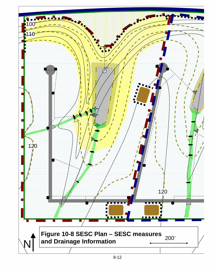
NFigure 10-8 SESC Plan – SESC measuresand Drainage Information 200’
8-13
Sm
ithD
rain
120
115
105
Trout River
Roadway Property Boundary
Existing Contours (ft) Proposed Contours (ft)
Regulated Wetland
Rip Rap Energy Dissipater
Stone Check Dam
Curb/Gutter Inlet
Topsoil Stockpile
Storm Sewer
Double Net Erosion Blanket
Single Net Erosion Blanket
Sediment Basin
Outlet Riser with Gravel Jacket
Aggregate Access Road
Silt Fence
Concrete Culvert
Hydroseed/Straw Mulch
Polyacrilamide Treatment
Phase 1 Limits
Phase 2 Limits
See attached construction notes, construction details,and construction schedule for more SESC information
72d
Str
eet
8-14
200’
100
105
110
115120
125
120
120
115
110
72nd
Str
eet
145th Avenue
Trout River
Sm
ithD
rain
Site Location14600 72nd Street
Jones TwpAllegan Cnty32.8 acres
Residences
Metea Sandy LoamMarlette Silty Clay Loam
Houghton Muck
N
Pond
Figure 10-9: Site Location Sketch and Soils Information
Construction SchedulePhase 1: Begin Construction Approximately August 1, 2011
Week 1: Install Smith Drain Crossing and Rip Rap Stabilization. Install AggregateAccess Road.
Week 2: Clear and grade site entrance road and roadside ditches working awayfrom Smith Drain. Install Seed, Erosion Blankets, and Check Dams at thecompletion of each days work.
Weeks 3-5: Install Sediment Basin and Silt Fence. Clear and grub topsoil storageareas. Clear, grub, scrape topsoil, and grade only as necessary to facilitateinstallation and stabilization of these areas. Stabilize with topsoil, seed, erosionblankets and/or mulch as specified after installation.
Weeks 5-7: Clear, grub, scrape topsoil, and rough grade swales, slopes along thewetland boundary, and concentrated flow areas.
Weeks 6-8: Finish grade, replace topsoil, hydroseed, and install erosion blankets,and/or check dams on swales, slopes along wetland boundary, and concentratedflow areas. Complete installation within 5 days after area has reached final grade.
8-15
Weeks 8-10: Clear, grub, scrape topsoil, and rough grade in remaining areas inPhase 1 (upland areas near future roads).
Weeks 10-12: Finish grade, replace topsoil, and hydroseed any remaining exposedareas in Phase 1. Complete hydroseeding within 5 days after area has reached finalgrade. Any areas which cannot be hydroseeded by October 16 must thereafter behydroseeded and additionally mulched at a rate of 2 tons of straw per acre.
Weeks 13+: Install road base, road surface, curb and gutter, storm water system,and utilities as weather allows. Stabilize disturbed areas with seed and 2 tons ofstraw per acre within 5 days of completion of each area.
Phase 2: Begin Construction Approximately March 15, 2011Weeks 1-3: Install Sediment Basin and Silt Fence. Clear and grub topsoil storageareas. Clear, grub, scrape topsoil, and grade only as necessary to facilitateinstallation and stabilization of these areas. Stabilize with topsoil, seed, erosionblankets, and/or mulch as specified after installation.
Weeks 4-7: Clear, grub, scrape topsoil, and rough grade swales, slopes along thewetland boundary, and concentrated flow areas. Install polyacrylamide treatmentsystems at swale outlets upon earth change.
Weeks 5-8: Finish grade, replace topsoil, and install erosion blankets, and/or checkdams on swales, slopes along wetland boundary, and concentrated flow areas.Complete installation within 5 days after area has reached final grade.
Weeks 9-11: Clear, grub, scrape topsoil, and rough grade in remaining areas inPhase 2 (upland areas near future roads).
Weeks 10-12: Finish grade, replace topsoil, and hydroseed any remaining exposedareas in Phase 1. Complete hydroseeding within 5 days after area has reached finalgrade.
Weeks 12+: Install road base, road surface, curb and gutter, storm water system,and utilities as weather allows. Install polyacrylamide treatment system, at stormwater system outlets into sediment basin immediately upon completion. Stabilizedisturbed areas with hydroseed and 2 tons of straw per acre within 5 days ofcompletion of each area.
Construction NotesGeneral – All structures and SESC measures shall be installed and managed inaccordance with manufacturer recommendations and the plan details provided. Ifneither is provided, the default standards from the 2003 Michigan Department ofTransportation Standard Specifications for Construction shall be followed.
Limits of Earth Change – No areas outside those in Phase 1 and Phase 2 shall becleared, grubbed, or graded at any time during the project. Phase 2 constructionshall not begin until Phase 1 is fully completed.
8-16
Proposal for ongoing maintenance of permanent SESC measures – PermanentSESC measures will be monitored by the property owner until which time theproperty or portion of the property is sold. Failures will be corrected immediately.
Aggregate Access Road – Aggregate materials shall be added or replaced as poorspace becomes filled with sediment. The aggregate may be removed or paved overwhen the project is complete.
Concentrated Flow Areas and Ditches – Avoid construction during rain events orwhen rain/snowmelt is forecasted. Scouring and bank failure shall be correctedimmediately.
Sediment Basin – Shall be constructed and stabilized as early during theconstruction process as possible; and before any other grading on the project. Thebasin must be restored to full design depth once sediment accumulation exceeds50% of the design wet depth. The sediment basin may be modified into apermanent storm water basin once all areas within the drainage area are stabilizedwith permanent vegetation.
Silt Fence – Shall be installed prior to any grading at the project. Silt fenceinstallation shall not cross any concentrated flow areas. Silt fence must bemaintained and/or replaced at failure or when sediment reaches 50% of the height ofthe fence. All silt fence shall be removed once the drainage area is stabilized withpermanent vegetation.
Check Dams – Shall be installed at the frequency and location identified in the plans.Accumulated sediment behind check dams shall be removed when it reaches 50%of the height at the center of the check dam. Check dams may be removed oncechannelized flows are stabilized with permanent vegetation.
Erosion Blanket – Shall be placed on slopes and channels as located on the plans.Topsoil should be graded as smoothly as possible prior to placement. Installationshall be consistent with specifications provided and manufacturer’srecommendations. Erosion blanket failure shall be repaired immediately.
Curb and Gutter Inlets – Curb and gutter inlets shall be protected withpremanufactured inlet protection devices at all times. Inlet protection devices maybe removed once all runoff contributing areas are stabilized with permanent SESCmeasures. All inlet protection devices shall be removed once the drainage area ispermanently stabilized.
Seed/Hydroseed/Straw Mulch – All areas noted to be seeded utilizing a hydroseedmixture of 2000 lbs per acre hardwood fiber mulch with tackifier. Hydroseeding afterOctober 16 and before April 1 shall be additionally stabilized by evenly spreading 2tons of straw per acre that is properly anchored. All seed mixes shall be 90% orgreater pure live seed. Any areas which fail to establish dense permanent stands ofvegetation must be reseeded. The following seed mixes shall be used during thenoted time periods:Apr 1 – Sep 30 (200 lbs/acre)
8-17
50% Perennial Ryegrass, 30% Creeping Red Fescue, 20% Kentucky BluegrassOct 1 – Freeze/Snow & Thaw – March 31 (220 lbs/acre)50% Perennial Rye, 30% Creeping Fescue, 15% Kentucky Bluegrass, 5% WinterWheat (Fall), Spring Wheat (Spring), or Annual RyegrassSeeding outside the growing season may require follow up mowing of establishedannual grasses to limit competition with perennial grasses.
Polyacrylamide (PAM) Treatment – Shall be accomplished with partially hydrated gelblocks of a specific PAM chemical makeup which has been tested and proveneffective at flocculating on-site soils. The number and placement of PAM treatmentblocks shall be determined by the engineer based on manufacturerrecommendations.
Dust Control – If dry weather conditions persist such that dust is transported outsideproperty boundaries or into the on-site wetland area to the north, any exposed soilson the site shall be wetted via water truck or irrigation equipment. Water applicationshall be up to, but not beyond the point that applied water begins to runoff. Waterapplications shall be repeated as necessary.
Construction DetailsConstruction details and drawings showing proper installation should be included inthe SESC plan for each of the SESC measures utilized at the site. These shouldinclude material specifications and plan, profile, and cross-section drawings asapplicable. See Appendix I for examples of construction details. The actualconstruction details provided must identify specific materials and measurables asnecessary to properly construct SESC measures.
SummaryThe preceding information and exercises were intended to give the reader anintroductory experience with reviewing and developing SESC plans. Although thereare often many ways to solve SESC issues at construction sites, it is important torecognize the capabilities and limitations of each type of SESC measure. Inaddition, good SESC planning requires significant knowledge about the site, theconstruction process, seasonal limitations, and the objectives of the owner(s).
The plan developed in this unit meets all the minimum requirements of Rule 1703.In addition, it properly utilizes specific SESC measures as part of a system. If theplan is properly implemented, inspected, and modified as necessary in the future,the example project is likely to maintain compliance with the requirements of Part 91.
Appendix 8A-1
Appendix 10ACompleted Example of Exercise 1
1703 Required Plan Components:
Map (plan) with a scaled drawing of not more than 200 feet to the inchIt appears that the plan does indeed meet this criterion. However, it appears thatthe site continues to the east where the apparent access road enters the site. Ifthe earth change will continue into this area, the plan submitted would not meetthis criterion. If the earth change is to extend into the access road, it would affectwhether or not most of the other following criteria are met.A site location sketchNo specific site location can be ascertained from the plan provided.The proximity of the proposed earth change to lakes and streamsThis criterion is not met because there is no clear delineation of where the earthchanges will be occurring at the site.Predominant land featuresWhile this information should be confirmed with an on-site inspection, the hillsslopes, swales, river, and wetlands at the site are identified.Existing and proposed contour intervals or slope descriptionA soils survey or written description of the soils of the anticipated exposedland areaNo soils information is provided.A description and the location of the physical limits of each proposed earthchangeWhile most of the site boundaries appear to be provided, the plan does notspecifically identify the limits of the earth change. Therefore, the location andeffectiveness of measures cannot be identified.A description and the location of all existing and proposed on-site drainageand dewatering facilitiesThe plan does include storm water drainage infrastructure locations andtopographic information necessary to identify surface drainage.The timing and sequence of each proposed earth changeNo timing and sequencing information provided. With the scale and riskassociated with this project, when and how the project is undertaken couldsignificantly change the SESC measures necessary.The location and description for installing and removing all proposedtemporary SESC measuresThe location of on-site silt fence is provided, but description information ismissing. Also, additional temporary controls may be required.A description and the location of all proposed permanent SESC measuresThe road bases and rip rap outlets identified are permanent erosion controlmeasures. However, no information is provided as to what will be used (i.e.vegetation) to stabilize the other areas of the project.A program proposal for the continued maintenance of all permanent SESCmeasures, including the person responsible for the maintenanceWhile meeting this component generally does not require extensive details, noinformation is provided.
Appendix 8A-2
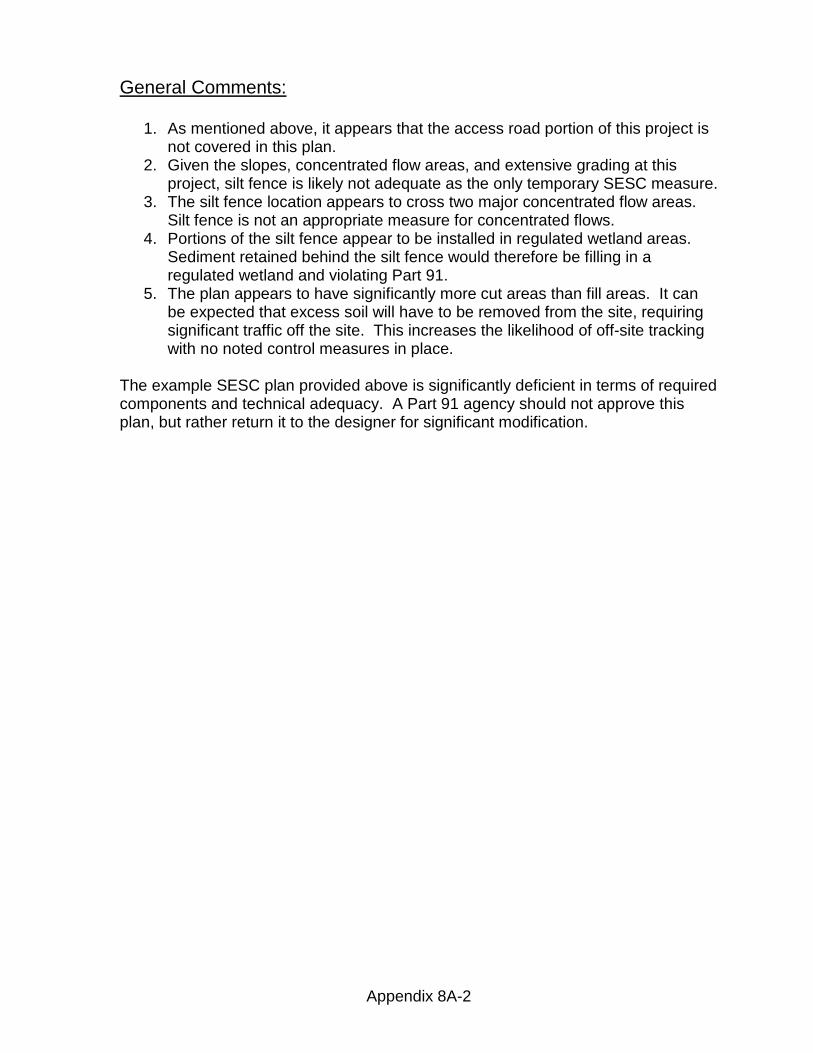
General Comments:
1. As mentioned above, it appears that the access road portion of this project isnot covered in this plan.
2. Given the slopes, concentrated flow areas, and extensive grading at thisproject, silt fence is likely not adequate as the only temporary SESC measure.
3. The silt fence location appears to cross two major concentrated flow areas.Silt fence is not an appropriate measure for concentrated flows.
4. Portions of the silt fence appear to be installed in regulated wetland areas.Sediment retained behind the silt fence would therefore be filling in aregulated wetland and violating Part 91.
5. The plan appears to have significantly more cut areas than fill areas. It canbe expected that excess soil will have to be removed from the site, requiringsignificant traffic off the site. This increases the likelihood of off-site trackingwith no noted control measures in place.
The example SESC plan provided above is significantly deficient in terms of requiredcomponents and technical adequacy. A Part 91 agency should not approve thisplan, but rather return it to the designer for significant modification.
Appendix 8B-1
Appendix 10BCompleted Example of Exercises 2A and 2B
Activity: Clear and Grub throughVegetative StabilizationConcern: Sediment control of fineparticles on western portion of siteSolutions: Prioritize erosion control andstabilization, Polymer sediment controls
Activity: Clear and Grub throughVegetative StabilizationConcern: Erosion and or sedimentcontrol in the two major swales on-siteSolutions: Prioritize stabilization,sediment basins, check dams, erosionblankets
Activity: Smith Drain CrossingConcern: Work in and adjacent to astream
Solutions: Stabilize quickly, utilizeturbidity curtains or coffer dams duringconstruction, detailed design criteria
Activity: Clear and Grub Veg.Concern: Large areas of exposedsoil/Destabilizing critical areasSolutions: Scheduling/staging, utilizewood chips and woody debris fromclearing, limit scope of clearing, installtemporary SESC measures.
Activity: Scrape and Store TopsoilConcern: Large areas of exposedsoil/Destabilizing critical areasSolutions: Scheduling/staging, limitscope of clearing, temporary SESC
measures, prioritize stabilization ofcritical areas
Activity: Scrape and Store TopsoilConcern: Topsoil stockpile erosion andlossSolutions: Setback from sensitiveareas and concentrated flow areas,avoid areas receiving runoff, stabilizewith vegetation, contain with perimetercontrols
Activity: Scrape and Store Topsoilthrough Rough GradeConcern: Exposed soils in winter/springSolutions: Scheduling/staging, stabilizewith vegetation in growing season,cover crop, mulching, erosion blankets
Solutions: Scheduling, prioritizecompletion and stabilization, checkdams, erosion control blankets
Activity: Install Storm Water SystemConcern: Control sediment inputs intostorm water system and discharge intosensitive areasSolutions: Prioritize stabilization, inletprotection, direct to treatment
Activity: Finish Grade/TopsoilConcern: Slippage or washout oftopsoilSolutions: Subsoil/topsoil interfaceroughness, erosion control measures incritical areas
Activity: Seed/StabilizeConcern: Establishment/FailureSolutions: Seed selection, mulch, soilamendment, irrigation due to season,
Appendix 8D-1
Appendix 10DCompleted Example from Exercise 4
SESC Plan for Phase 1
200’
Sm
ithD
rain
120
120
Roadway Property Boundary
Existing Contours (ft) Proposed Contours (ft)
Regulated Wetland
Rip Rap Energy Dissipater
Stone Check Dam
Curb/Gutter Inlet
115
105Topsoil Stockpile
Storm Sewer
Double Net Erosion Blanket
Single Net Erosion Blanket
Sediment Basin
Outlet Riser with Gravel Jacket
Aggregate Access Road
Silt Fence
Concrete Culvert
NTrout River
Hydroseed/Straw Mulch
Phase 1 Example Construction Schedule
Begin Construction Approximately August 1, 2011
Week 1: Install Smith Drain Crossing Culvert, Rip Rap Stabilization, and AggregateAccess Road
Week 2: Clear and grade site entrance road and roadside ditches working awayfrom Smith Drain. Install Seed, Erosion Blankets, and Check Dams at thecompletion of each days work.
Weeks 3-5: Install Sediment Basin and Silt Fence. Clear and grub topsoil storageareas. Clear, grub, scrape topsoil, and grade only as necessary facilitate installationand stabilization of these areas. Stabilize with seed and mulch as specified afterinstallation.
Weeks 5-7: Clear, grub, scrape topsoil, and rough grade swales, slopes along thewetland boundary, and concentrated flow areas.
Appendix 8D-2
Weeks 6-8: Finish grade, replace topsoil, hydroseed, and install erosion blankets,and/or check dams on swales, slopes along wetland boundary, and concentratedflow areas. Complete installation within 5 days after area has reached final grade.
Weeks 8-10: Clear, grub, scrape topsoil, and rough grade in remaining areas inPhase 1 (upland areas near future roads).
Weeks 10-12: Finish grade, replace topsoil, and hydroseed any remaining exposedareas in Phase 1. Complete hydroseeding within 5 days after area has reached finalgrade. Any areas which cannot be hydroseeded by October 16 must thereafter behydroseeded and additionally mulched at a rate of 2 tons of straw per acre.
Weeks 13+: Install road base, road surface, curb and gutter, storm water system,and utilities as weather allows. Stabilize disturbed areas with hydroseed and 2 tonsof straw per acre within 5 days of completion of each area.
Construction Notes (Decision making commentary in italics):
General – All structures and SESC measures shall be installed and managedin accordance with manufacturer recommendations and the plan detailsprovided. If neither is provided, the default standards from the 2003 MichiganDepartment of Transportation Standard Specifications for Construction shallbe followed.
Limits of Earth Change – No areas outside those in Phase 1 and Phase 2 shallbe cleared, grubbed, or graded at any time during the project. Phase 2construction shall not begin until Phase 1 is fully completed.
Proposal for ongoing maintenance of permanent SESC measures – PermanentSESC measures will be monitored by the property owner until which time theproperty or portion of the property is sold. Failures will be correctedimmediately.Fulfills a Rule 1703 Plan Requirement
Concrete Culverts – Shall be installed in accordance with details andspecifications providedThere are many types of culverts and channel crossing options available. As ageneral rule, culverts that span the entire high flow channel and allow for naturalsubstrate are preferable environmentally. The height of installation of closedculverts is critical. They should never be placed to high (causing a spill pool andblocking fish passage) or too low (restricting high flow events).
Aggregate Access Road – Aggregate materials shall be added or replaced aspoor space becomes filled with sediment. The aggregate may be removed orpaved over when the project is complete.Given the amount of expected construction traffic an aggregate access road isabsolutely necessary for this project. One special concern is the Smith Drain nearthe site egress. Therefore, the length of the aggregate access road was increased
Appendix 8D-3
beyond the minimum 50’ length to promote sediment removal at a greater distancefrom the drain.
Concentrated Flow Areas and Ditches – Avoid construction during rain eventsor when rain/snowmelt is forecasted. Scouring and bank failure shall becorrected immediately.The site information included in this chapter addressed concerns related to theneighbor’s house and the pond to the east of the project. Runoff from the entranceroad would have travelled toward this neighbor’s property. Therefore, diversionswith check dams for sediment removal were provided in order to divert runoff into theSmith Drain. Check dams provide only limited sediment removal; therefore,stabilizing this area rapidly was given a high priority in scheduling.
Sediment Basin – Shall be constructed and stabilized as early during theconstruction process as possible; and before any other grading on theproject. The basin must be restored to full design depth once sedimentaccumulation exceeds 50% of the design wet depth. The sediment basin maybe modified into a permanent storm water basin once all areas within thedrainage area are stabilized with permanent vegetation.The on-site swales provide excellent locations for sediment basins which can treatmost of the runoff from the site. Adding a sediment basin required changes to theproposed grade and relocation of the storm sewer outlets to increase flow path priorto discharge. The sandy loam soils in this area should allow for effective sedimentremoval by the basin. Given the design criteria for sediment basins provided inChapter 9, the recommended basin size for the drainage area is 92’X370’x2’. Thiswas amended slightly to fit site constraints. Please note that this drainage areaincludes several acres to the south of the site. The basin size could be reduced ifdiversion of the off-site runoff is possible.
Silt Fence – Shall be installed prior to any grading at the project. Silt fenceinstallation shall not cross any concentrated flow areas. Silt fence must bemaintained and/or replaced at failure or when sediment reaches 50% of theheight of the fence. All silt fence shall be removed once the drainage area isstabilized with permanent vegetation.The silt fence at the site is installed parallel to contour lines and curved upslope atthe terminal ends to prevent runoff circumventing the fence. The drainage areacontributing runoff to the silt fence does not exceed ½ acre per 100’ of fence. Also,note that the silt fence is installed upslope from the sediment basin. The silt fencelikely would fail in this concentrated flow area. The basin provides treatment of thiswater. The silt fence installed along the eastern property line of the project wasincluded to provide treatment for runoff from the small area of disturbance whichflows northeasterly along that area.
Topsoil StockpilesStockpiles were placed in upland areas, with minimal runoff contributing areasupslope. Maximum feasible distance from sensitive areas should be maintained.Given the short duration of stockpiling, one pile was allowed in the northeastquadrant somewhat close to the slope and wetland, hopefully minimizing haulingdistance and facilitating stabilization of nearby critical areas.
Appendix 8D-4
Check Dams – Shall be installed at the frequency and location identified in theplans. Accumulated sediment behind check dams shall be removed when itreaches 50% of the height at the center of the check dam. Check dams may beremoved once channelized flows are stabilized with permanent vegetation.The spacing provided on the plan assumes a 2.5’ height in the center of the dam.Therefore, there are 2 check dams for every 5’ contour line.
Erosion Blanket – Shall be placed on slopes and channels as located on theplans. Topsoil should graded as smoothly as possible prior to placement.Installation shall be consistent with specifications provided andmanufacturers recommendations. Erosion blanket failure shall be repairedimmediately.Erosion blankets specifications are highly dependent on slope length, slopesteepness, and velocity and depth of runoff water. Specific blankets and installationguidelines should be specified.
Curb and Gutter Inlets – Curb and gutter inlets shall be protected withpremanufactured inlet protection devices at all times. Inlet protection devicesmay be removed once all runoff contributing areas are stabilized withpermanent SESC measures. All inlet protection devices shall be removedonce the drainage area is permanently stabilized.All curb and gutter inlets flow into the sediment basin. Therefore, installation of inletprotection will probably provide little additional protection of sensitive areas.However, it will help to ensure proper function of the storm water system.
Seed/Hydroseed/Straw Mulch – All areas noted to be seeded utilizing ahydroseed mixture of 2000 lbs per acre hardwood fiber mulch with tackifier.Hydroseeding after October 16 and before April 1 shall be additionallystabilized by evenly spreading 2 tons of straw per acre that is properlyanchored. All seed mixes shall be 90% or greater pure live seed. Any areaswhich fail to establish dense permanent stands of vegetation must bereseeded. The following seed mixes shall be used during the noted timeperiods:Apr 1 – Sep 30 (200 lbs/acre)50% Perennial Ryegrass, 30% Creeping Red Fescue, 20% Kentucky BluegrassOct 1 – Freeze/Snow & Thaw – March 31 (220 lbs/acre)50% Perennial Rye, 30% Creeping Fescue, 15% Kentucky Bluegrass, 5%Winter Wheat (Fall), Spring Wheat (Spring), or Annual RyegrassSeeding outside the growing season may require follow up mowing ofestablished annual grasses to limit competition with perennial grasses.An alternative seed mix and additional mulching is required for seeding that occursoutside the recommended seeding dates in spring and fall. In this case, an annualcompanion crop is added. A companion crop provides rapid germination andestablishment, preventing erosion and protecting the seed bed. Also, the speciesselected will continue to grow well outside the normal growing season for manyother types of grasses.
Appendix 8D-5
Dust Control – If dry weather conditions persist such that dust is transportedoutside property boundaries or into the on-site wetland area to the north, anyexposed soils on the site shall be wetted via water truck or irrigationequipment. Water application shall be up to, but not beyond the point thatapplied water begins to runoff. Water applications shall be repeated asnecessary.
Construction Details
For this example project, SESC construction/installation details and materialspecifications are necessary for each of the following: Sediment basin, riser outlet,check dams, energy dissipaters, silt fence, culvert installations, concentrated flowchannels, aggregate access road, and catch basin installation. Details andspecifications are not provided in this example. Please see the specification sheetsin Chapter 9 for more information and example details
Appendix 8E-1
Appendix 10ECompleted Example from Exercise 5
Example SESC Plan for Phase 2 (Exercise 5)
120
120115
Trout River
110
100
120
200’N
Roadway Property Boundary
Existing Contours (ft) Proposed Contours (ft)
Regulated Wetland
Rip Rap Energy Dissipater
Stone Check Dam
Curb/Gutter Inlet
Topsoil Stockpile
Storm Sewer
Double Net Erosion Blanket
Single Net Erosion Blanket
Sediment Basin
Outlet Riser with Gravel Jacket
Aggregate Access Road
Silt Fence
Concrete Culvert
Hydroseed/Straw Mulch
Polyacrilamide Treatment
Phase 2 Limits
Phase 2 Example Construction Schedule
Start Phase 2 approx. March 15, 2012 as weather allows
Weeks 1-3: Install Sediment Basin and Silt Fence. Clear and grub topsoil storageareas. Clear, grub, scrape topsoil, and grade only as necessary facilitate installationand stabilization of these areas. Stabilize with seed and mulch as specified afterinstallation.
Weeks 4-7: Clear, grub, scrape topsoil, and rough grade swales, slopes along thewetland boundary, and concentrated flow areas. Install polyacrylamide treatmentsystems at swale outlets upon earth change.
Weeks 5-8: Finish grade, replace topsoil, and install erosion blankets, and/or checkdams on swales, slopes along wetland boundary, and concentrated flow areas.Complete installation within 5 days after area has reached final grade.
Appendix 8E-2
Weeks 9-11: Clear, grub, scrape topsoil, and rough grade in remaining areas inPhase 2 (upland areas near future roads).
Weeks 10-12: Finish grade, replace topsoil, and hydroseed any remaining exposedareas in Phase 1. Complete hydroseeding within 5 days after area has reached finalgrade.
Weeks 12+: Install road base, road surface, curb and gutter, storm water system,and utilities as weather allows. Install polyacrylamide treatment system, at stormwater system outlets, into sediment basin immediately upon completion. Stabilizedisturbed areas with seed and 2 tons of straw per acre within 5 days of completion ofeach area.
Construction Notes (Decision making commentary in italics)
Include all notes from Phase 1
Erosion BlanketsPhase 2 of the site has significantly more erodible soils than those found in Phase 1.Therefore, more critical areas exist. In addition, the fine textured soils will reducethe effectiveness of sediment control measures, making erosion control moreimportant.
Polyacrylamide (PAM) Treatment – Shall be accomplished with partiallyhydrated gel “logs” of a specific PAM chemical makeup which has been testedand proven effective at flocculating on-site soils. The number and placementof PAM treatment logs shall be determined by the engineer based onmanufacturer recommendations.PAMs were utilized on this portion of the site because the soil type (Silty Clay Loam)is erodible and comprised of fine particles. Therefore, the sediment basin is likely tobe ineffective without the addition of PAMs. In general, PAMs are very soil specific;therefore, the on-site soils must be tested to assure proper function of the system.Also, the sediment basin receives runoff from both concentrated flows and sheetflow. Therefore, specific hydrologic information is required to determine the numberand location of PAM logs.
Construction Details
Include all details from Phase 1.
Specifications and drawings should be provided for the PAM treatment system andPhase 2 sediment basin.