16
UNIT HEATERS High Efficiency Heating Equipment SUH-6

UNIT HEATERS High Effi ciency Heating Equipment
SUH-6

Effi cient Heating Solutions for all Applications
Sterling unit heaters provide effi cient heating solutions
for all residential and commercial applications. Choose
from several model confi gurations using the latest
high effi ciency tubular heat exchangers as well as
traditional clamshell heat exchangers in both propeller
and blower models with capacities from 30 MBH to
400 MBH.
Our complete line of unit heaters allows customers
to order the exact size and options needed to
ensure optimum energy saving performance. From
residential and commercial garages and workshops
to warehouses, factories, shipping areas and public
buildings, Sterling HVAC has the perfect-fi t unit
heater solution for all applications.
Heat Exchanger Technology
Unlike other competitive heat exchangers that feature
lightweight construction, Sterling high effi ciency
tubular heat exchangers, available in aluminized or
stainless steel, use an industry leading heavy-duty
20-gauge minimum metal standard in production.
Sterling heat exchangers are designed to be the most
reliable and energy effi cient available today providing
superior performance and durability.
Ease of Service and Installation
All Sterling unit heaters are designed for ease of
installation, service and annual maintenance. All
components are easily accessed to save time and
money on all maintenance calls.
Warranty and Factory Assurance
All unit heaters are covered by a full 10-year
warranty (unless otherwise noted) covering the heat
exchanger, fl ue collector and burners. Each unit is
factory fi re-tested to ensure proper operation at the
time of installation.
2

Contents PAGE
Tubular Propeller & Blower
GG Series (Residential and Commercial Certifi ed) 4
TF/TC Series (Commercial) 5
Shield GF Series (Greenhouse) 6
SF/SC Series (Separated Combustion) 7
Hydronic Unit Heaters
HS Series (Horizontal Header and Serpentine) 8
VS Series (Vertical Hot Water and Steam) 9
Indoor Duct Furnaces
QVED/QVES (Power Vent) 10
QVSD Series (Separated Combustion) 11
Oil Fired
QVOF Series 12
Vent Pipe Sizes 13
3

GG Series Low-Profi le, Residential Garage and Commercial Certifi ed The GG heater is a tubular design propeller type unit heater that utilizes a single orifi ce burner. Low profi le design and sizes ranging from 30-120 MBH make it ideal for all applications.
STANDARD FEATURES
• 20-Gauge Aluminized Steel Tubular Heat Exchangers
• 7 Sizes Ranging from 30 to 120 MBH• Single Orifi ce Burner• Direct Spark Ignition System• 20-Gauge Jacket Panels w/Baked Enamel Finish• Easy Access Control Panel• Certifi ed for Category I and III Venting• 82+% Thermal Effi ciency• ETL Certifi ed• OSHA Type Fan Guard• Field Convertible to Separated Combustion with Combustion Air Inlet Kit (Optional)
Tubular Propeller
4

TF/TC Series Latest Tubular Heat Exchanger Technology TF/TC unit heaters combine the latest tubular heat exchanger and In-Shot burner technology with the quality and reliability you have come to know with Sterling. Available in sizes 100 - 400 MBH.
STANDARD FEATURES
• Propeller (TF) and Blower (TC) Models Available • 20-Gauge Aluminized Steel Tubular Heat
Exchangers• 9 Sizes Ranging from 100 to 400 MBH• In-Shot Burner Technology• Direct Spark Ignition System• 20-Gauge Jacket Panels w/Baked Enamel Finish• Power Vented• Easy Access Control Panel• Certifi ed for Category I and III Venting• Terminal Strip Low Voltage Wiring• 83% Thermal Effi ciency• ETL Certifi ed• Single Stage Gas Valve• 2-Stage and Modulating Gas Valve (Optional)• Stainless Steel Tubular Heat Exchanger
(Optional)
Tubular Propeller & Blower
5
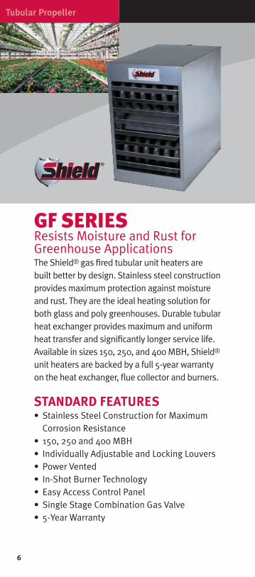
GF SERIESResists Moisture and Rust for Greenhouse Applications The Shield® gas fi red tubular unit heaters are built better by design. Stainless steel construction provides maximum protection against moisture and rust. They are the ideal heating solution for both glass and poly greenhouses. Durable tubular heat exchanger provides maximum and uniform heat transfer and signifi cantly longer service life. Available in sizes 150, 250, and 400 MBH, Shield® unit heaters are backed by a full 5-year warranty on the heat exchanger, fl ue collector and burners.
STANDARD FEATURES
• Stainless Steel Construction for Maximum Corrosion Resistance
• 150, 250 and 400 MBH• Individually Adjustable and Locking Louvers• Power Vented• In-Shot Burner Technology• Easy Access Control Panel• Single Stage Combination Gas Valve• 5-Year Warranty
Tubular Propeller
6
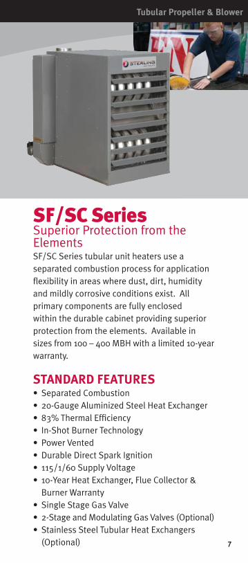
SF/SC SeriesSuperior Protection from the ElementsSF/SC Series tubular unit heaters use a separated combustion process for application fl exibility in areas where dust, dirt, humidity and mildly corrosive conditions exist. All primary components are fully enclosed within the durable cabinet providing superior protection from the elements. Available in sizes from 100 – 400 MBH with a limited 10-year warranty.
STANDARD FEATURES
• Separated Combustion • 20-Gauge Aluminized Steel Heat Exchanger • 83% Thermal Effi ciency • In-Shot Burner Technology • Power Vented • Durable Direct Spark Ignition • 115/1/60 Supply Voltage • 10-Year Heat Exchanger, Flue Collector &
Burner Warranty• Single Stage Gas Valve• 2-Stage and Modulating Gas Valves (Optional)• Stainless Steel Tubular Heat Exchangers
(Optional)
Tubular Propeller & Blower
7

HS Series Header Type and Serpentine Type Models are Ideal for Hot Water Installations HS Series horizontal unit heaters are ideal for hot water installations. A wide range of outputs and airfl ows allows virtually unlimited fl exibility in job design. Sterling horizontal unit heaters are available in both serpentine and header type units. Serpentine units offer outputs from 8,030 to 35,900 BTU’s and are ideal for hot water installations with limited clearances. Header type horizontal units range from 18,000 to 360,000 and can operate with either hot water or steam. Both units are furnished with totally enclosed motors as standard equipment, explosion proof motors are optional.
STANDARD FEATURES
• Horizontal Louvers Standard• Thermostats Feature ‘Off-Auto’ and ‘Auto-Fan-Off’• Copper Tube-Aluminum Fin Hydronic Coil• ETL Certifi ed• Strap-On Water Control (Optional)• Steam Pressure Control (Optional)• Vertical Louvers (Optional)
Hydronic Unit Heaters
8
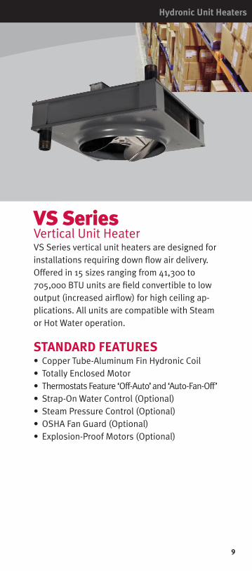
VS SeriesVertical Unit HeaterVS Series vertical unit heaters are designed for installations requiring down fl ow air delivery. Offered in 15 sizes ranging from 41,300 to 705,000 BTU units are fi eld convertible to low output (increased airfl ow) for high ceiling ap-plications. All units are compatible with Steam or Hot Water operation.
STANDARD FEATURES
• Copper Tube-Aluminum Fin Hydronic Coil• Totally Enclosed Motor• Thermostats Feature ‘Off-Auto’ and ‘Auto-Fan-Off’• Strap-On Water Control (Optional)• Steam Pressure Control (Optional)• OSHA Fan Guard (Optional)• Explosion-Proof Motors (Optional)
Hydronic Unit Heaters
9

QVED/QVES Series Power Vented Duct FurnacesQVED and QVES are power vented indoor duct furnaces. Model QVED offers bottom burner access and is typically ceiling suspended. The model QVES offers side access and is typi-cally mounted on a non-combustible fl oor and includes factory installed power vent and sealed fl ue collector that controls combus-tion and excess air during on cycles.
STANDARD FEATURES
• ETL Certifi ed for 80% Thermal Effi ciencies• 10 Sizes Ranging from 100-400 MBH• Aluminized Steel Heat Exchanger - 20-Gauge• Optional 409 and 321 Stainless Steel Heat
Exchangers• Single Stage Gas Valve • Spark Ignition• Natural or LP Gas Available• Easy Burner Access with Individually
Removable Burners• 2-Stage and Modulating Gas Valves (Optional)
Indoor Duct Furnaces
10

QVSD Series Separated Combustion for Mildly Hostile EnvironmentsQVSD separated combustion indoor duct furnace is designed to be installed in mildly hostile environments where dusty, dirty, and mildly corrosive conditions exist or high humidity or slightly negative pressures prevail.The burners, pilot and fl ue system are enclosed within the unit. The entire combustion process is literally unaffected by the atmosphere in the space where the unit is located.
STANDARD FEATURES
• ETL Certifi ed for 80% Thermal Effi ciencies• 10 Sizes Ranging from 100-400 MBH• Aluminized Steel Heat Exchanger - 20-Gauge• Single Stage Gas Valve • Spark Ignition• Natural or LP Gas Available• Easy Burner Access with Individually
Removable Burners• 2-Stage and Modulating Gas Valves (Optional)• 409 and 321 Stainless Steel Heat Exchangers
(Optional)
Indoor Duct Furnaces
11

QVOF SeriesQVOF Series oil-fi red unit heater is designed to operate on number 1 & 2 fuel oils. Available in seven sizes ranging from 70 – 560 MBH (.50 to 4.00 GPH) all units are factory assembled and ready to install.
STANDARD FEATURES
• Heavy Duty 18-Gauge Heat Exchanger • Energy Effi cient Flame Retention Beckett
Burner • Adjustable Discharge Louvers • Fan/Limit Control • Four Point Suspension • CAD Cell Burner Safeguard Control • 115/1/60
Oil Fired
12

Vent Pipe Sizes
Vent Pipe Sizes
Model Sizes Vent Pipe DiameterSTANDARD VENTING
GG 030-120 4"
TF/GF/TC100-250 5"300-400 6"
QVED, QVES100-175 4"200-250 5"300-400 6"
SEPARATED COMBUSTION
GG030-075 4"090-120 5"
QVSD100-175 4"200-250 5"300-400 6"
SF/SC100-250 5"300-400 6"
13
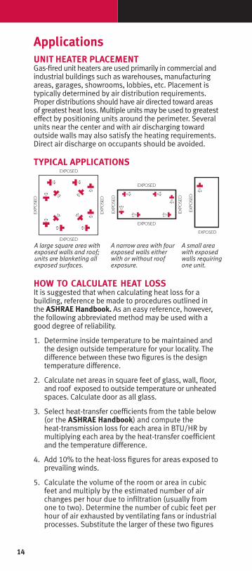
ApplicationsUNIT HEATER PLACEMENT
Gas-fi red unit heaters are used primarily in commercial and industrial buildings such as warehouses, manufacturing areas, garages, showrooms, lobbies, etc. Placement is typically determined by air distribution requirements. Proper distributions should have air directed toward areas of greatest heat loss. Multiple units may be used to greatest effect by positioning units around the perimeter. Several units near the center and with air discharging toward outside walls may also satisfy the heating requirements. Direct air discharge on occupants should be avoided. TYPICAL APPLICATIONS
HOW TO CALCULATE HEAT LOSS
It is suggested that when calculating heat loss for a building, reference be made to procedures outlined in the ASHRAE Handbook. As an easy reference, however, the following abbreviated method may be used with a good degree of reliability.
1. Determine inside temperature to be maintained and the design outside temperature for your locality. The difference between these two fi gures is the design temperature difference.
2. Calculate net areas in square feet of glass, wall, fl oor, and roof exposed to outside temperature or unheated spaces. Calculate door as all glass.
3. Select heat-transfer coeffi cients from the table below (or the ASHRAE Handbook) and compute the heat-transmission loss for each area in BTU/HR by multiplying each area by the heat-transfer coeffi cient and the temperature difference.
4. Add 10% to the heat-loss fi gures for areas exposed to prevailing winds.
5. Calculate the volume of the room or area in cubic feet and multiply by the estimated number of air changes per hour due to infi ltration (usually from one to two). Determine the number of cubic feet per hour of air exhausted by ventilating fans or industrial processes. Substitute the larger of these two fi gures
A large square area with exposed walls and roof; units are blanketing all exposed surfaces.
A narrow area with four exposed walls either with or without roof exposure.
A small area with exposed walls requiring one unit.
14
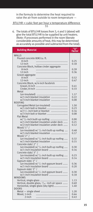
Building Material
WALLS Poured concrete 80#/cu. ft. 8-inch .............................................. 0.25 12-inch .............................................. 0.18 Concrete Block, hollow cinder aggregate 8-inch .............................................. 0.39 12-inch .............................................. 0.36 Gravel aggregate 8-inch .............................................. 0.52 12-inch .............................................. 0.47 Concrete Block, w/4-inch facebrick Gravel, 8-inch .............................................. 0.41 Cinder, 8-inch .............................................. 0.33 Metal (un-insulated) ............................................. 1.17 w/1-inch blanket insulation ........................ 0.22 w/3-inch blanket insulation ........................ 0.08ROOFING Corrugated Metal (un-insulated) ........................ 1.50 w/1-inch bolt or blanket .............................. 0.23 w/11/2
-inch bolt or blanket ........................ 0.16 w/3-inch bolt or blanket .............................. 0.08 Flat Metal w/ 3/8
-inch built-up roofi ng ......................... 0.90 w/1-inch blanket insulation under deck ...... 0.21 w/2-inch blanket insulation under deck ...... 0.12 Wood/ 1" / (un-insulated) w/ 3/8
-inch built-up roofi ng .... 0.48 w/1-inch blanket insulation ........................ 0.17 Wood/ 2" / (un-insulated) w/ 3/8 -inch built-up roofi ng ..... 0.32 w/1-inch blanket insulation ........................ 0.15 Concrete slab/ 2" / (un-insulated) w/ 3/8
-inch built-up roofi ng ..... 0.30 w/1-inch insulation board ........................... 0.16 Concrete slab/ 3" / (un-insulated) w/ 3/8 -inch built-up roofi ng ..... 0.23 w/1-inch insulation board ........................... 0.14 Gypsum slab/ 2" / (un-insulated) w/ 1/2
-inch gypsum board ....... 0.36 w/1-inch insulation board ........................... 0.20 Gypsum slab/ 3" / (un-insulated) w/ 1/2
-inch gypsum board ....... 0.30 w/1-inch insulation board ........................... 0.18WINDOWS Vertical, single-glass ........................................ 1.13 Vertical, double-glass, 3/16
- inch air space ....... 0.69 Horizontal, single-glass (sky light) .................... 1.40DOORS Metal — single sheet ....................................... 1.20 Wood, 1-inch .............................................. 0.64 2-inch .............................................. 0.43
"U" Factor
in the formula to determine the heat required to raise the air from outside to room temperature —
BTU/HR = cubic feet per hour x temperature difference55
6. The totals of BTU/HR losses from 3, 4 and 5 (above) will give the total BTU/HR to be supplied by unit heaters. (Note: If processes performed in the room liberate considerable amounts of heat, this may be determined as accurately as possible and subtracted from the total).
15

260 NORTH ELM ST. WESTFIELD, MA 01085(413) 568-9571 • FAX: (413) 562-5311
www.sterlinghvac.com
ALSO AVAILABLE FROM STERLING: • Cabinet Blowers• Low Intensity Infrared Heaters• High Intensity Infrared Heaters• Outdoor Duct Furnaces• Evaporative Coolers• Air Handlers• Gas-Fired Make-Up Air Systems
ENERGYPERFORMANCE
VERIFIED
RENDEMENTENERGETIQUE
VERIFIE
CM
VERIFIED
INTERTEK


![LCD 400 - mesteksa.commesteksa.com/fileuploads/Literature/RBI Water Heaters/LCD Series... · [27.3 cm] 5 in [12.7 cm] OPERATING STATUS: 33 11/16 in [85.6 cm] 35 3/16 in [89.4 cm]](https://static.documents.pub/doc/80x56/5f464bac2dfa3415ab3e03be/lcd-400-water-heaterslcd-series-273-cm-5-in-127-cm-operating-status.jpg)


