Page 1
UNIT-I
Automobile electrical and electronics
Electrical components in automobile
Automobile electrical system has gradually evolved over the years and today it assimilates
automatic computer control of the automotive mechanics. In the early days, automobiles
electrical system comprised of only basic wiring technologies that were used for distributing
power to other parts of a vehicle. It had only switches, wires, relays and controlled motors as its
key components but today’s electrical system includes sensors, actuators, alternators, battery,
oxygen sensors, generator, starter solenoid, starter drive, high power electrical system and other
devices.
Components of automobile electrical system
1. armature
2. automobile battery
3. automobile ignition system
4. automobile starting system:
5. automotive computer chips
6. automotive electrical wiring:
7. charging system
8. spark plugs
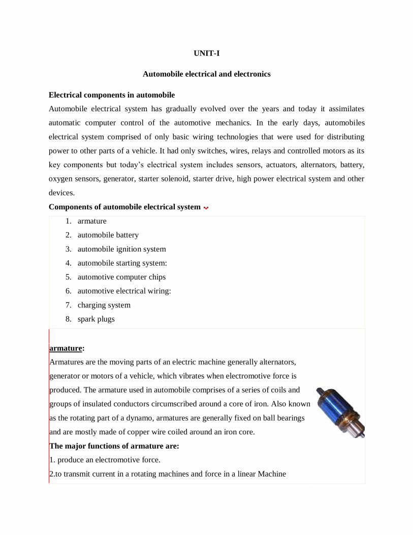
armature:
Armatures are the moving parts of an electric machine generally alternators,
generator or motors of a vehicle, which vibrates when electromotive force is
produced. The armature used in automobile comprises of a series of coils and
groups of insulated conductors circumscribed around a core of iron. Also known
as the rotating part of a dynamo, armatures are generally fixed on ball bearings
and are mostly made of copper wire coiled around an iron core.
The major functions of armature are:
1. produce an electromotive force.
2.to transmit current in a rotating machines and force in a linear Machine
Page 2
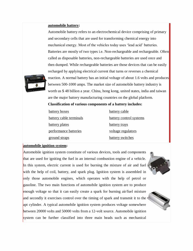
automobile battery:
Automobile battery refers to an electrochemical device comprising of primary
and secondary cells that are used for transforming chemical energy into
mechanical energy. Most of the vehicles today uses ‘lead acid’ batteries.
Batteries are mostly of two types i.e. Non-rechargeable and rechargeable. Often
called as disposable batteries, non-rechargeable batteries are used once and
then dumped. While rechargeable batteries are those devices that can be easily
recharged by applying electrical current that turns or reverses a chemical
reaction. A normal battery has an initial voltage of about 1.6 volts and produces
between 500-1000 amps. The market size of automobile battery industry is
worth us $ 48 billion a year. China, hong kong, united states, india and taiwan
are the major battery manufacturing countries on the global platform.
Classification of various components of a battery includes:
battery boxes
battery cable terminals
battery plates
performance batteries
ground straps
battery cable
battery control systems
battery trays
voltage regulators
battery switches
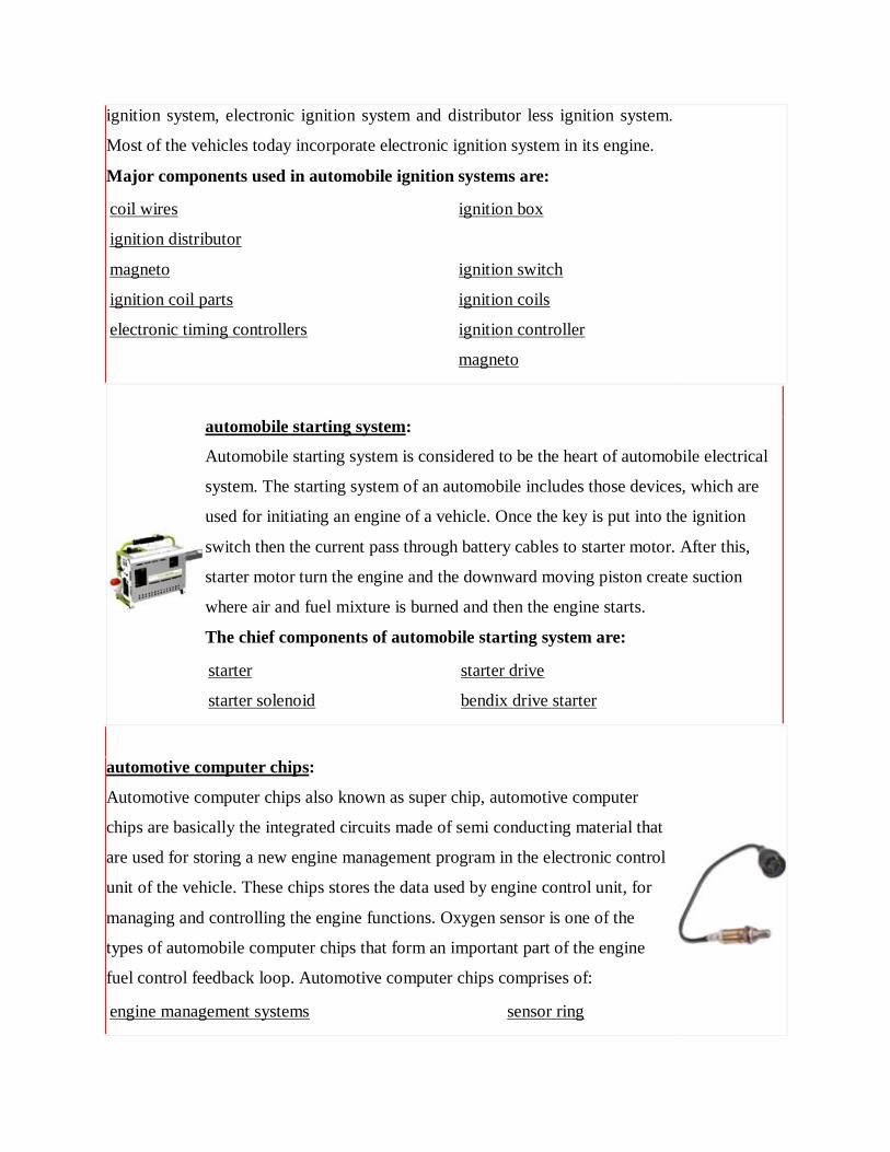
automobile ignition system:
Automobile ignition system constitute of various devices, tools and components
that are used for igniting the fuel in an internal combustion engine of a vehicle.
In this system, electric current is used for burning the mixture of air and fuel
with the help of coil, battery, and spark plug. Ignition system is assembled in
only those automobile engines, which operates with the help of petrol or
gasoline. The two main functions of automobile ignition system are to produce
enough voltage so that it can easily create a spark for burning air/fuel mixture
and secondly it exercises control over the timing of spark and transmit it to the
apt cylinder. A typical automobile ignition system produces voltage somewhere
between 20000 volts and 50000 volts from a 12-volt source. Automobile ignition
system can be further classified into three main heads such as mechanical
Page 3
ignition system, electronic ignition system and distributor less ignition system.
Most of the vehicles today incorporate electronic ignition system in its engine.
Major components used in automobile ignition systems are:
coil wires
ignition distributor
magneto
ignition coil parts
electronic timing controllers
ignition box
ignition switch
ignition coils
ignition controller
magneto
automobile starting system:
Automobile starting system is considered to be the heart of automobile electrical
system. The starting system of an automobile includes those devices, which are
used for initiating an engine of a vehicle. Once the key is put into the ignition
switch then the current pass through battery cables to starter motor. After this,
starter motor turn the engine and the downward moving piston create suction
where air and fuel mixture is burned and then the engine starts.
The chief components of automobile starting system are:
starter
starter solenoid
starter drive
bendix drive starter
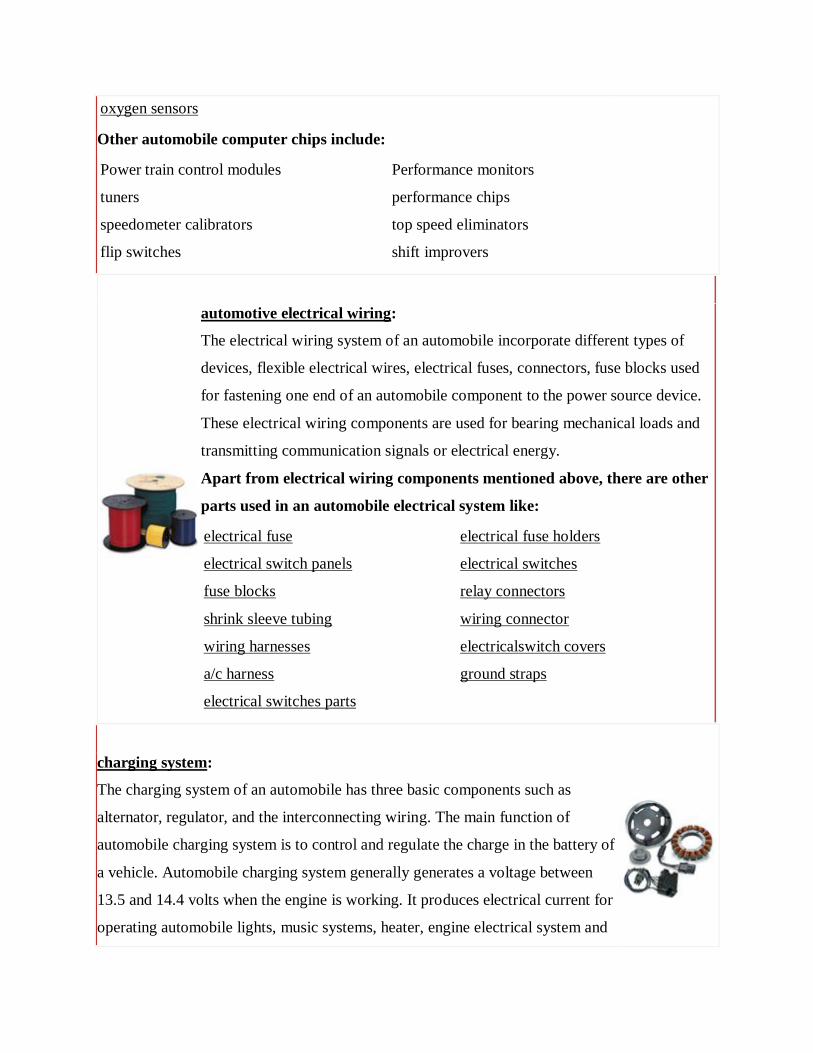
automotive computer chips:
Automotive computer chips also known as super chip, automotive computer
chips are basically the integrated circuits made of semi conducting material that
are used for storing a new engine management program in the electronic control
unit of the vehicle. These chips stores the data used by engine control unit, for
managing and controlling the engine functions. Oxygen sensor is one of the
types of automobile computer chips that form an important part of the engine
fuel control feedback loop. Automotive computer chips comprises of:
engine management systems sensor ring
Page 4
oxygen sensors
Other automobile computer chips include:
Power train control modules
tuners
speedometer calibrators
flip switches
Performance monitors
performance chips
top speed eliminators
shift improvers
automotive electrical wiring:
The electrical wiring system of an automobile incorporate different types of
devices, flexible electrical wires, electrical fuses, connectors, fuse blocks used
for fastening one end of an automobile component to the power source device.
These electrical wiring components are used for bearing mechanical loads and
transmitting communication signals or electrical energy.
Apart from electrical wiring components mentioned above, there are other
parts used in an automobile electrical system like:
electrical fuse
electrical switch panels
fuse blocks
shrink sleeve tubing
wiring harnesses
a/c harness
electrical switches parts
electrical fuse holders
electrical switches
relay connectors
wiring connector
electricalswitch covers
ground straps
charging system:
The charging system of an automobile has three basic components such as
alternator, regulator, and the interconnecting wiring. The main function of
automobile charging system is to control and regulate the charge in the battery of
a vehicle. Automobile charging system generally generates a voltage between
13.5 and 14.4 volts when the engine is working. It produces electrical current for
operating automobile lights, music systems, heater, engine electrical system and
Page 5
other electrical components.
Other components of charging system of the vehicle are:
alternator
automobile generator
alternator parts
Alternator bearing
alternator fans
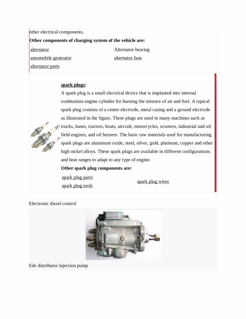
spark plugs:
A spark plug is a small electrical device that is implanted into internal
combustion engine cylinder for burning the mixture of air and fuel. A typical
spark plug consists of a center electrode, metal casing and a ground electrode
as illustrated in the figure. These plugs are used in many machines such as
trucks, buses, tractors, boats, aircraft, motorcycles, scooters, industrial and oil
field engines, and oil burners. The basic raw materials used for manufacturing
spark plugs are aluminum oxide, steel, silver, gold, platinum, copper and other
high nickel alloys. These spark plugs are available in different configurations
and heat ranges to adapt to any type of engine.
Other spark plug components are:
spark plug parts
spark plug tools spark plug wires
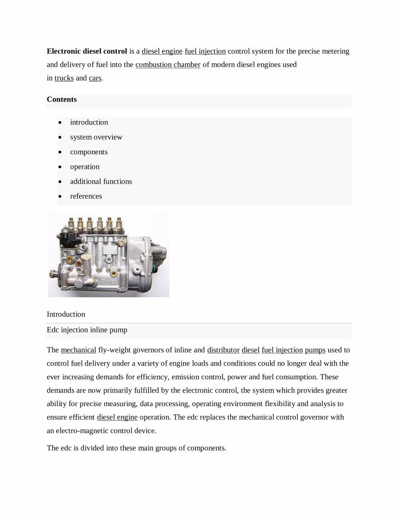
Electronic diesel control
Edc distributor injection pump
Page 6
Electronic diesel control is a diesel engine fuel injection control system for the precise metering
and delivery of fuel into the combustion chamber of modern diesel engines used
in trucks and cars.
Contents
introduction
system overview
components
operation
additional functions
references
Introduction
Edc injection inline pump
The mechanical fly-weight governors of inline and distributor diesel fuel injection pumps used to
control fuel delivery under a variety of engine loads and conditions could no longer deal with the
ever increasing demands for efficiency, emission control, power and fuel consumption. These
demands are now primarily fulfilled by the electronic control, the system which provides greater
ability for precise measuring, data processing, operating environment flexibility and analysis to
ensure efficient diesel engine operation. The edc replaces the mechanical control governor with
an electro-magnetic control device.
The edc is divided into these main groups of components.
Page 7
electronic sensors for registering operating conditions and changes. A wide array
of physical inputs is converted into electrical signal outputs.
actuators or solenoids which convert the control unit's electrical output signal into
mechanical control movement.
ecm (electronic control module ) or engine ecu (electronic control unit) with microprocessors
which process information from various sensors in accordance with programmed software
and outputs required electrical signals into actuators and solenoids.
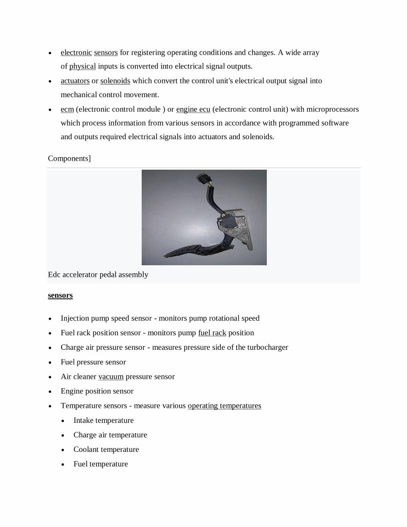
Components]
Edc accelerator pedal assembly
sensors
Injection pump speed sensor - monitors pump rotational speed
Fuel rack position sensor - monitors pump fuel rack position
Charge air pressure sensor - measures pressure side of the turbocharger
Fuel pressure sensor
Air cleaner vacuum pressure sensor
Engine position sensor
Temperature sensors - measure various operating temperatures
Intake temperature
Charge air temperature
Coolant temperature
Fuel temperature
Page 8
exhaust temperature (pyrometer)
Ambient temperature
Vehicle speed sensor - monitors vehicle speed
Brake pedal sensor - operates with cruise control, exhaust brake, idle control
Clutch pedal sensor - operates with cruise control, exhaust brake, idle control
Accelerator pedal sensor
Driver input switches - cruise control, idle increase /decrease, engine/exhaust brake
Injector needle movement sensor - monitors the actual injection time and feeds the
information to the ecu (as used on vm motori 2.5 and 3.1 engines)
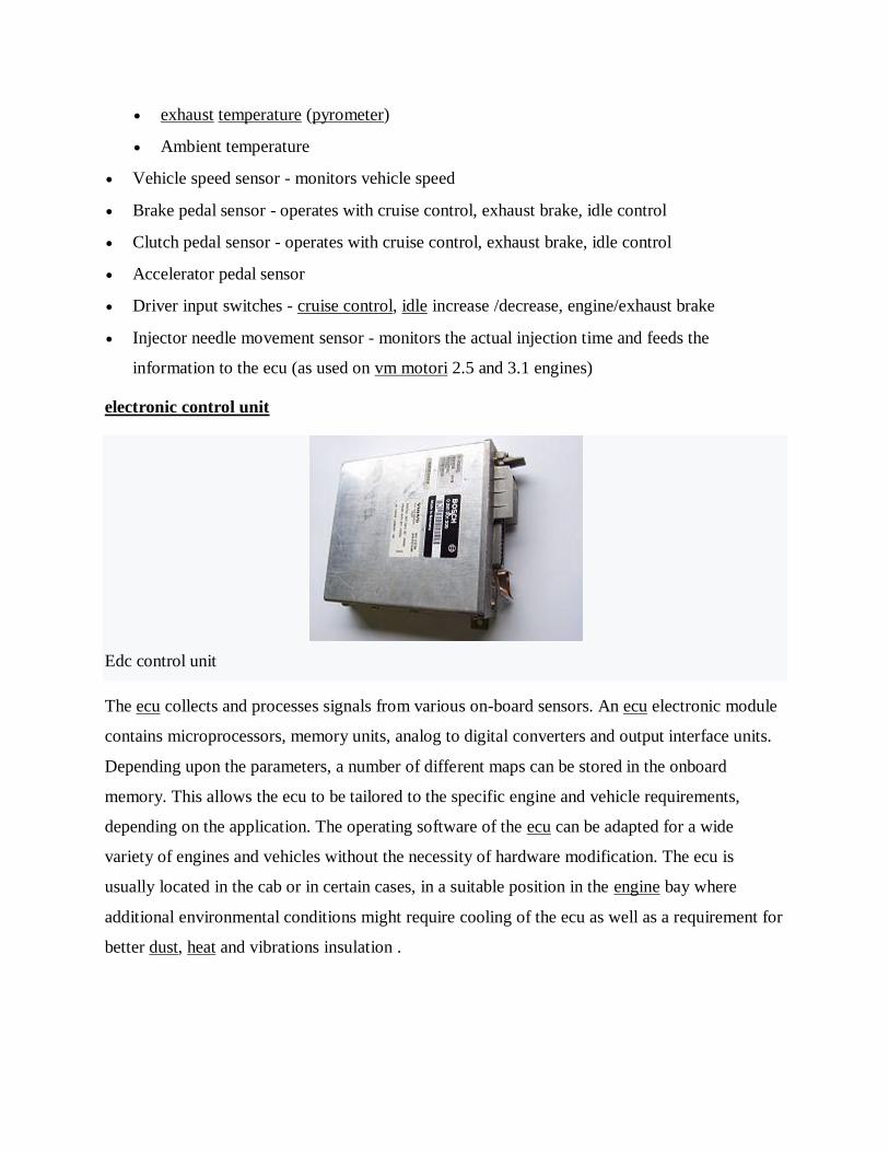
electronic control unit
Edc control unit
The ecu collects and processes signals from various on-board sensors. An ecu electronic module
contains microprocessors, memory units, analog to digital converters and output interface units.
Depending upon the parameters, a number of different maps can be stored in the onboard
memory. This allows the ecu to be tailored to the specific engine and vehicle requirements,
depending on the application. The operating software of the ecu can be adapted for a wide
variety of engines and vehicles without the necessity of hardware modification. The ecu is
usually located in the cab or in certain cases, in a suitable position in the engine bay where
additional environmental conditions might require cooling of the ecu as well as a requirement for
better dust, heat and vibrations insulation .
Page 9
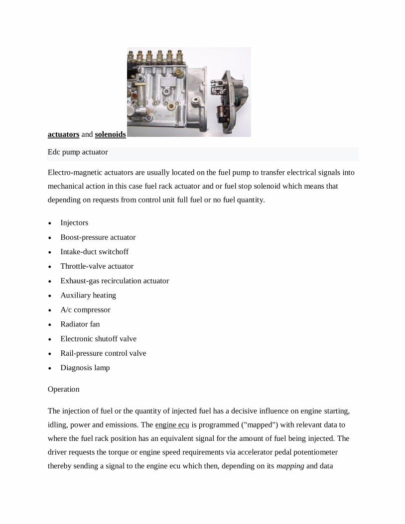
actuators and solenoids
Edc pump actuator
Electro-magnetic actuators are usually located on the fuel pump to transfer electrical signals into
mechanical action in this case fuel rack actuator and or fuel stop solenoid which means that
depending on requests from control unit full fuel or no fuel quantity.
Injectors
Boost-pressure actuator
Intake-duct switchoff
Throttle-valve actuator
Exhaust-gas recirculation actuator
Auxiliary heating
A/c compressor
Radiator fan
Electronic shutoff valve
Rail-pressure control valve
Diagnosis lamp
Operation
The injection of fuel or the quantity of injected fuel has a decisive influence on engine starting,
idling, power and emissions. The engine ecu is programmed ("mapped") with relevant data to
where the fuel rack position has an equivalent signal for the amount of fuel being injected. The
driver requests the torque or engine speed requirements via accelerator pedal potentiometer
thereby sending a signal to the engine ecu which then, depending on its mapping and data
Page 10
collected from various sensors, calculates in real time the quantity of injected fuel required, thus
altering the fuel rack to the required position. The driver can also input additional commands
such as idle speed increase to compensate e.g. For ptooperation which can be either variably set
or has a preset speed which can be recalled. The road speed function can be used to evaluate
vehicle speed and possibly activate a speed limiter (heavy vehicles), or maintain or restore a set
speed (cruise control). Further functions can include exhaust brake operation which, when
activated, will result in the fuel pump rack position being set to zero delivery or idle. The engine
ecu can also interface with various other vehicle systems e.g. Traction control and carry out self
monitoring duties and self diagnostic functions to keep the system working at an optimal level.
To ensure the safe operation in case of failure, the limp home mode functions are also integrated
into the system, e.g. Should the pump speed sensor fail the ecu can use an alternator speed signal
function for engine rpms counter as a backup signal.
Additional functions
Engine protection, cold start - when starting cold, engine rpms are limited.
Engine protection, overheating - when overheating, to avoid damage the engine power
output is limited.
Remote engine shutdown - when auxiliary equipment is in use e.g. Crane in case of rollover.
Constant engine speed - the engine maintains set revs irrespective of load e.g. Pto operation
Environmental legislation for pollution
Air pollution control ordinance
This ordinance empowers the epd to control air pollution from industry, commercial
operations and construction work. [motor vehicle emissions are controlled under the road
traffic ordinance and the epd also helps to control these]. The apco prohibits the use of
high sulphur and leaded fuels and the open burning of construction waste, tyres and cables
for metal salvage.
Abatement notices are usually issued to anyone causing air pollution from a process or
machinery and they will be asked to reduce or stop their emissions, or face prosecution.
Page 11
Some events are prosecuted on the spot, such as construction dust or black smoke
emissions. Potential polluters whose fuel consumption exceeds a certain limit must submit
plans for installing or altering furnaces, ovens and chimneys. Major industrial processes,
or "specified processes", are subject to tighter control. The methods and standards for
assessing air pollution can be found in the technical memorandum for issuing air pollution
abatement notices.
Asbestos control provisions in the ordinance require that building works involving
asbestos must be conducted only by registered qualified personnel and under the
supervision of a registered consultant.
Air pollution control (volatile organic compounds) regulation:
the regulation prohibits import into hong kong and manufacture in hong kong regulated
products with volatile organic compounds content exceeding the prescribed limits for local
sale or use. The regulated products include architectural paints, vehicle refinishing paints,
vessel paints, pleasure craft paints, adhesives, sealants, printing inks and six categories of
consumer products (namely air fresheners, hairsprays, multi-purpose lubricants, floor wax
strippers, insecticides, and insect repellents).
Air pollution control (non-road mobile machinery) (emission) regulation:
this regulation covers non-road mobile machinery (nrmms) include a wide range of mobile
machines (including transportable industrial equipment), or vehicles powered by internal
combustion engines used primarily off-road. All regulated machines sold or leased for use
in hong kong, except those exempted, are required to comply with the prescribed emission
standards. Starting from 1 december 2015, only approved or exempted nrmms with a
proper label are allowed to be used in specified activities and locations including
construction sites, container terminals and back up facilities, restricted areas of the airport,
designated waste disposal facilities and specified processes.
Air pollution control (ocean going vessels) (fuel at berth) regulation:
this regulation bans ocean going vessels from using fuel with sulphur content exceeding
0.5% during berthing in hong kong.
Page 12
T is prohibited to dump waste in public places or on government land, or on private
premises without the consent of the owner or occupier. Apart from this general provision,
there are four major provisions under the waste disposal ordinance:
waste disposal (chemical waste) (general) regulation:
anyone who produces chemical waste or causes it to be produced has to register as a
chemical waste producer. The waste must be packaged, labelled and stored properly before
disposal. Only a licensed collector can transport the waste to a licensed chemical waste
disposal site for disposal. Chemical waste producers also need to keep records of their
chemical waste disposal for inspection by epd staff.
Waste disposal (livestock waste) regulations:
livestock farmers must dispose of livestock waste without causing pollution or nuisance to
the environment. Liquid waste has to be disposed of either to a soakaway-pit or treated to
meet effluent standards of 50 mg/l of biochemical oxygen demand and 50 mg/l of
suspended solids.
Import and export of waste control:
a permit system to control the import and export of hazardous and other waste in line with
the requirements of the basel convention, is set out in this ordinance.
Waste disposal (clinical waste) (general) regulation:
clinical waste producers must properly manage their clinical waste by consigning the
clinical waste to licensed clinical waste collectors for delivery to a licensed disposal
facility for disposal. The waste must be packaged, labeled and stored properly before
disposal. Only a licensed collector can transport the waste to a licensed clinical waste
disposal site for disposal. Clinical waste producer also need to keep records of their
clinical waste consignment and delivery records for inspection by epd staff.
All discharges, other than domestic sewage to a foul sewer or unpolluted water to a storm
drain, must be covered by an effluent discharge licence. The licence specifies the
permitted physical, chemical and microbial quality of the effluent and the general
Page 13
guidelines are that the effluent does not damage sewers or pollute inland or inshore marine
waters. Details of the effluent standards can be found in the technical memorandum on
effluent is charges.
Legal controls also apply to sewerage connections. The government is extending public
sewers to some major rural areas in an effort to improve the environment there. In areas
where these new sewers become available, a notice would be issued asking owners to
connect their sewage to the public sewer. If necessary, a further notice may be issued
asking the owner to demolish or fill in any redundant sewage treatment facilities or septic
tanks and soakaway-pits.
Neighborhood noise and noise from construction, industrial and commercial activities are
controlled by the noise control ordinance. Neighbourhood noise in the context of providing
quick relief to the public is generally controlled by the police.
Construction noise:
noisy construction work and the use of powered mechanical equipment in populated areas
is not allowed between 7pm and 7am or at any time on general holidays, unless prior
approval has been granted by the epd through the construction noise permit system.
Certain equipment is also subject to restrictions when its use is allowed. Hand-held
percussive breakers and air compressors must comply with noise emissions standards and
be issued with a noise emission label from the epd. Percussive pile-driving is allowed on
weekdays only with prior approval, in the form of a construction noise permit from the
epd.
Industrial and commercial noise:
industrial and commercial noise must comply with statutory limits specified in the
technical memorandum. Operators who fail to do so will be issued with a noise abatement
notice asking them to reduce their noise or face prosecution for failing to comply with the
conditions in the notice.
This ordinance controls the production, import and export of products containing ozone-
Page 14
depleting substances, and the recycling of ozone-depleting substances, thereby giving
effect to hong kong's international obligations under the 1985 vienna convention and the
1987 montreal protocol.
Anyone involved in marine dumping and related loading operations, requires a permit
from the epd. All dumping vessels have to be equipped with an automatic self-monitoring
system which records their position and loading and dumping operations.
The environmental impact assessment ordinance is to avoid, minimize and control the
adverse impact on the environment of designated projects through the application of the
environmental impact assessment process and the environmental permit system.
Designated projects, unless exempted, must follow the statutory environmental impact
assessment (eia) process and require environmental permits for their construction and
operation.
The ordinance regulates, through an activity-based permit system, the import, export,
manufacture and use of non-pesticide hazardous chemicals that have potentially harmful or
adverse effects on human health or the environment, including those regulated by the
stockholm convention and the rotterdam convention.
Producer responsibility scheme (prs) is a key policy initiative under the holistic waste
management system for waste reduction, recovery and recycling. Enshrining the principle
of "polluter pays" and the element of "eco-responsibility", prs requires manufacturers,
importers, wholesalers, retailers and consumers to share the responsibility of reducing,
recovering and recycling certain products so as to minimize their environmental impact.
The ordinance is a framework legislation which provides the shared core elements of all
prss and the fundamental regulatory requirements in respect of individual types of product,
with operational details to be set out in the ordinance and its subsidiary legislation.
The environmental levy scheme on plastic shopping bags is the first prs under the
ordinance, and the law sets out the details of the operation of the prs. Starting from 1 april
2015, the prs is fully extended to cover all retail sales of goods. Sellers involving in retail
Page 15
sales of goods shall charge the customer 50 cents or more for each plastic shopping bag
provided directly or indirectly to the customer. Offenders may be subject to a fixed penalty
of $2,000.
The ordinance prohibits drivers from causing or permitting their vehicle engines to operate
for more than 3 minutes in aggregate in any 60-minute period while the vehicles are
stationary ("idling prohibition"). Drivers who contravene the idling prohibition may be
issued with a penalty notice requiring them to pay a fixed penalty of $320. Traffic wardens
and environmental protection inspectors are empowered to enforce the law.
Overview of electronic system
Electrical and electronic system content in both automotive and commercial vehicles will
continue to become more complex as new technologies are accepted and implemented. From
vehicle level integration requirements to individual subsystem and component design validation,
exponent’s vehicle electronics group has significant expertise and industry experience that
includes powertrain, body, chassis, safety, and entertainment electrical and electronic systems
hardware and software. Our staff has experience designing and analyzing vehicle wiring and
circuits, starting and charging systems, batteries, motors, switches, lamps, internal combustion
and hybrid engine management systems, instrumentation, power mirrors and windows, automatic
headlamp aiming, heads-up display, electric assist power steering, wireless tire pressure
monitoring, electronic suspension control, antilock brakes, electronic stability control, traction
control, electronic throttle control, electric brake systems, passive seat belt systems, mobile
communication systems, and front and side multi-stage supplemental restraint systems. Exponent
personnel are versed in the failure modes of high duty cycle sensors and actuators, both inert and
detrimental effects of electromagnetic interference, and relevant mitigation methods.
Exponent engineers and scientists are trained in taguchi’s robustness design practices including
total cost function, control factors, and life cycle cost management. In order to optimize product
design, validation, and life testing processes for vehicle electronic systems, our engineers have
implemented the design of experiments and are capable of exploring factors not understood or
previously considered during initial product design and development. Exponent’s professionals
have experience with methods for proactively reviewing designs of vehicle systems, such as
failure mode and effect analysis (fmea), and with methods of failure analysis, such as fault tree
Page 16
analysis (fta). We are often able to leverage our rich history of failure analysis experience to
design reviews to help our clients evaluate new systems.
From vehicle-level integration requirements to individual subsystem and component design
validation, exponent’s professionals have significant expertise and industry experience:
Powertrain control systems
Body control systems
Braking control systems
Engine control systems
Chassis control systems
Safety systems
Entertainment systems
Vehicle power and battery systems
Our consulting services include designing and analyzing:
Vehicle wiring and circuits
Starting and charging systems
Batteries
Actuators, motors, switches, and indicators
Internal combustion and hybrid engine management systems
Instrumentation
Power mirrors and windows
Automatic headlamp aiming
Heads-up display
Electric assist power steering
Seat heating systems
Wireless tire pressure monitoring
Electronic suspension control
Antilock brake systems
Electronic stability control
Traction control
Electronic throttle control
Electric brake systems
Page 17
Passive seat belt systems
Mobile communication systems
Front and side multi-stage supplemental restraint systems
Power train sub system
Higher performing power train & engine system components
The drive to reduce emissions and improve fuel economy is urgent, making every powertrain and
engine system component a candidate to improve efficiency, integrate function, reduce weight
and lower cost – areas where dupont excels.
Materials play a critical role in helping to reduce emissions, boost fuel economy and improve
efficiency in power train technologies. Dupont offers the broadest portfolio of materials capable
of withstanding today’s harsh engine environments and the most experienced and global
development staff to ensure solutions developed today are on the road tomorrow.
Increasing performance in automotive air ducts and turbocharger hoses
Leading the metals-to-plastics revolution in transmissions and driveline
Enhanced durability for extreme environments for sealed engine covers
Improving power train efficiency in charged air coolers
Thermal management through lighter weight engine cooling systems
Automotive chassis sub system
Automotive chassis is a skeletal frame on which various mechanical parts like engine, tires,
axle assemblies, brakes, steering etc. Are bolted. The chassis is considered to be the most
significant component of an automobile. It is the most crucial element that gives strength and
stability to the vehicle under different conditions. Automobile frames provide strength and
flexibility to the automobile. The backbone of any automobile, it is the supporting frame to
which the body of an engine, axle assemblies are affixed. Tie bars, that are essential parts of
automotive frames, are fasteners that bind different auto parts together.
automobile frames, automobile chassis automotive tie bar’
And tractor linkages parts
Page 18
automobile frames
Automotive frames are basically manufactured from steel. Aluminum is another raw material
that has increasingly become popular for manufacturing these auto frames. In an automobile,
front frame is a set of metal parts that forms the framework which also supports the front wheels.
It provides strength needed for supporting vehicular components and payload placed upon it.
Types of automobile frames
bonnet hood
bonnet:
Bonnet, an important part of automotive frame can be defined as a protective covering made up
of a hinged metal part used for covering an engine of a vehicle. Usually automobile bonnets are
made of steel, aluminum, fiberglass, and carbon fiber reinforced plastic.
hood:
Hood refers to a cover placed over the engine and passenger compartment of an automobile.
Hoods form an important type of automotive frames. These auto frame parts are usually made of
steel, aluminum, fiberglass, carbon fibre or dry carbon. A typical hood comprises of several
different parts such as hood ornament, hood scope, power bulge, and wiper jets.
automobile chassis
Automotive chassis is considered to be one of the significant structures of an automobile. It is
usually made of a steel frame, which holds the body and motor of an automotive vehicle. More
precisely, automotive chassis or automobile chassis is a skeletal frame on which various
mechanical parts like engine, tires, axle assemblies; brakes, steering etc are bolted. At the time of
manufacturing, the body of a vehicle is flexibly molded according to the structure of chassis.
Automobile chassis is usually made of light sheet metal or composite plastics. It provides
strength needed for supporting vehicular components and payload placed upon it. Automotive
chassis or automobile chassis helps keep an automobile rigid, stiff and unbending. Auto chassis
ensures low levels of noise, vibrations and harshness throughout the automobile. The different
Page 19
types of automobile chassis include:
ladder chassis: ladder chassis is considered to be one of the oldest forms of automotive chassis
or automobile chassis that is still used by most of the suvs till today. As its name connotes,
ladder chassis resembles a shape of a ladder having two longitudinal rails inter linked by several
lateral and cross braces.
Backbone chassis: backbone chassis has a rectangular tube like backbone, usually made up of
glass fibre that is used for joining front and rear axle together. This type of automotive chassis or
automobile chassis is strong and powerful enough to provide support smaller sports car.
Backbone chassis is easy to make and cost effective.
Monocoque chassis: monocoque chassis is a one-piece structure that prescribes the overall
shape of a vehicle. This type of automotive chassis is manufactured by welding floor pan and
other pieces together. Since monocoque chassis is cost effective and suitable for robotised
production, most of the vehicles today make use of steel plated monocoque chassis.
Types of automobile chassis
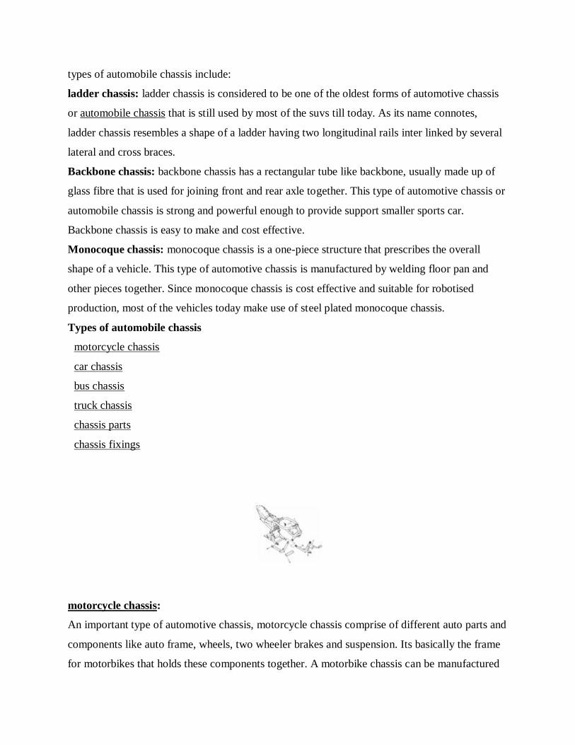
motorcycle chassis
car chassis
bus chassis
truck chassis
chassis parts
chassis fixings
motorcycle chassis:
An important type of automotive chassis, motorcycle chassis comprise of different auto parts and
components like auto frame, wheels, two wheeler brakes and suspension. Its basically the frame
for motorbikes that holds these components together. A motorbike chassis can be manufactured
Page 20
from different materials. But the commonly used materials are steel, aluminum, or magnesium.
Motorcycle easy ride frame
motorcycle frame cover
motorcycle frames and chassis
Motorcycle headlight trim kit
motorcycle light visors
motorcycle rigid frame
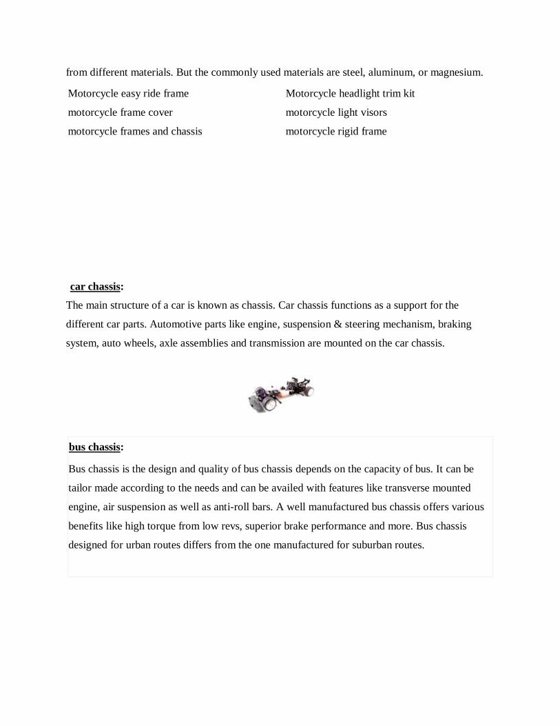
car chassis:
The main structure of a car is known as chassis. Car chassis functions as a support for the
different car parts. Automotive parts like engine, suspension & steering mechanism, braking
system, auto wheels, axle assemblies and transmission are mounted on the car chassis.
bus chassis:
Bus chassis is the design and quality of bus chassis depends on the capacity of bus. It can be
tailor made according to the needs and can be availed with features like transverse mounted
engine, air suspension as well as anti-roll bars. A well manufactured bus chassis offers various
benefits like high torque from low revs, superior brake performance and more. Bus chassis
designed for urban routes differs from the one manufactured for suburban routes.
Page 21
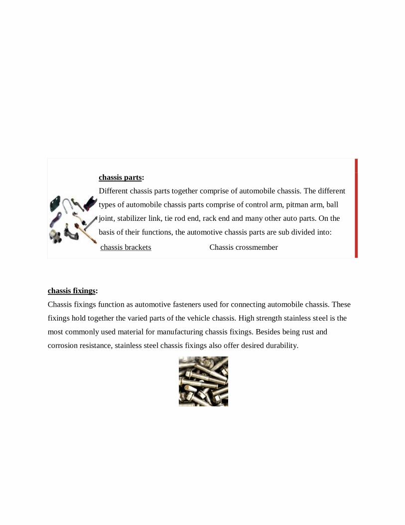
chassis parts:
Different chassis parts together comprise of automobile chassis. The different
types of automobile chassis parts comprise of control arm, pitman arm, ball
joint, stabilizer link, tie rod end, rack end and many other auto parts. On the
basis of their functions, the automotive chassis parts are sub divided into:
chassis brackets Chassis crossmember
chassis fixings:
Chassis fixings function as automotive fasteners used for connecting automobile chassis. These
fixings hold together the varied parts of the vehicle chassis. High strength stainless steel is the
most commonly used material for manufacturing chassis fixings. Besides being rust and
corrosion resistance, stainless steel chassis fixings also offer desired durability.
Page 22
automotive tie bar:
Tie bar refers to a metal rod or bar used for connecting pad of one lead frame to the rails of other
lead frame. More precisely this type of bar that is one of the types of automotive frames is used
for tying, fastening, binding or wrapping different parts or components of an automobile engine.
Different components of an automobile tie bar are:
ball hooks
pivot pin
uj cross
kingpin
tractor linkages parts:
Tractor linkage parts consist of whole ensemble of various spare auto parts and devices used for
joining or assembling the main parts of a tractor.
There is a wide variety of tractor linkages parts available in the market namely:
chain assembly
leveling box
eye bolt
linkage balls
link pin
u shackle
shackle pin
lift yokes
Gulf coast environmental systems supplies a fully automatic control system designed,
manufactured, and integrated into the product tailored to customer requirements. The control
system consist of a gces designed safety control system (scs). The scs system is designed to
optimize performance and safety per the national electric code and ul508a standards.
each scs is equipped with control logic to fully automate operation for the entire sequence of
operation. The single button start/stop design eliminates the possibility of costly operator error.
The scs performs automated diagnostic surveillance (self-checking) and reports system status.
The system incorporates state-of-the-art displays and graphics for reporting operational status
and fault / troubleshooting messages. The fault indicator displays messages defining the reason
for any departures from any operating normal operating parameters. The messages help identify
corrective action quickly and accurately, thus improving reliability.
Page 23
All safety control systems come with the option to interface with various plant dcs systems.
Communication to each scs programmable logic controller (plc) can occur through one of many
options including ethernet, fiber optics, or a modem.
Burner management systems (bms)
With each thermal oxidizer or industrial oven containing a burner system, a burner management
system (bms) with flame detection is incorporated into the safety control system. A burner flame
detection system consists of an arrangement of flame detectors, interlocks, and relays, and is part
of the bms. The purpose of the flame detection system is to sense flame operation and to shut off
any fuel supply if a hazardous condition develops. The flame detection system senses the
presence of a strong flame and proper combustion. System logic uses the information to control
the burner so that motors, blowers, ignition, and fuel valves are activated when needed, in the
proper sequence. In the event of a lost flame signal, the flame detection system signals the bms,
which then shuts down the fuel supply in order to keep unburned fuel from
accumulating.Combustion controls through gce systems
Although there are many places to buy a panel, an effective and practical combustion control
system requires a thorough understanding of combustion controls, and their interaction with the
burner system. Today’s demands are for high efficiency, low emissions, and maximum
productivity. A gces designed and engineered control system can pay for itself quickly.
Gulf coast environmental systems maintains a ul approved panel shop which insures quality and
on-time delivery as well as complete functional testing prior to shipment. These considerations
greatly reduce field commissioning time and enhance reliability. Gulf coast environmental
systems combustion design takes into account the realities of combustion control environmental
factors such as temperature and elevation, process stream, dust, vibration, and electrical noise.
Driver safety
safety for the driver is paramount. The reinforced cab structure with pre-programmed front and
rear crumple zones plays an important role here, as does the unique energy-absorbing
cab suspension. This means that the cab moves backwards in a controlled manner if there is a
rearendcollision. It remains as intact as possible and is still connected to the chassis. An airbag is
Page 24
available as an option. The dashboard has shock absorbing zones to limit or prevent potential
injury to the knees in the event of a collision. And daf’s unique night lock provides simple and
effective protection against break-ins and burglary.
Safety systems
the euro 6 daf cf and daf xf are delivered as standard with vehicle stability control (vsc), which
helps to prevent jack-knifing and overturning, adaptive cruise control (acc), forward collision
warning (fcw) and lane departure warning (ldws). These advanced safety and comfort systems
are available alongside daf’s advanced emergency braking (aebs), which helps to prevent
collisions or to limit their consequences. A camera/monitor system for an even better view on the
front and the passenger side of the truck is also optionally available.
Daf transport efficiency
also available as an option is predictive cruise control and predictive shifting. Both innovative
technologies contribute to daf’s transport efficiency philosophy and can reduce fuel consumption
and co2 emissions by 3%, especially when driving on hilly routes. Learn more about daf
transport efficiency.
Page 25
UNIT-2 INTRODUCTION TO EMBEDDED SYSTEMS
Embedded Systems definition
An embedded system is a computer system with a dedicated function within a larger mechanical
or electrical system, often with real-time computing constraints. It is embedded as part of a
complete device often including hardware and mechanical parts. Embedded systems control
many devices in common use today.
Microprocessor Embedded Systems
When developing embedded system hardware there is a choice of using a microprocessor or a
microcontroller - when using a microprocessor what are the best approaches
Embedded system tutorial includes
When developing an embedded system, one of the options is to base the computational
hardware around a microprocessor, MPU rather than a microcontroller, MCU.
Both approaches have their attractions, but generally they will be found in different
applications.
Microprocessor embedded systems will tend to be found in larger applications.
Microprocessor embedded systems tend to be more suitable for higher levels of
processing, where performance is key and space, power consumption and chip count are
less important.
Microprocessor basics
Microprocessors, MPUs are ideal for use in embedded systems, but their structure makes
them particularly applicable to certain types of embedded systems.
The basic MPU contains the central processing unit and possibly a few additional items
but the memory and also the Input Output interface is external. Typically the program is
stored in non-volatile memory, such as NAND or serial Flash, and at start-up is loaded
into an external DRAM and then commences execution.
Page 26
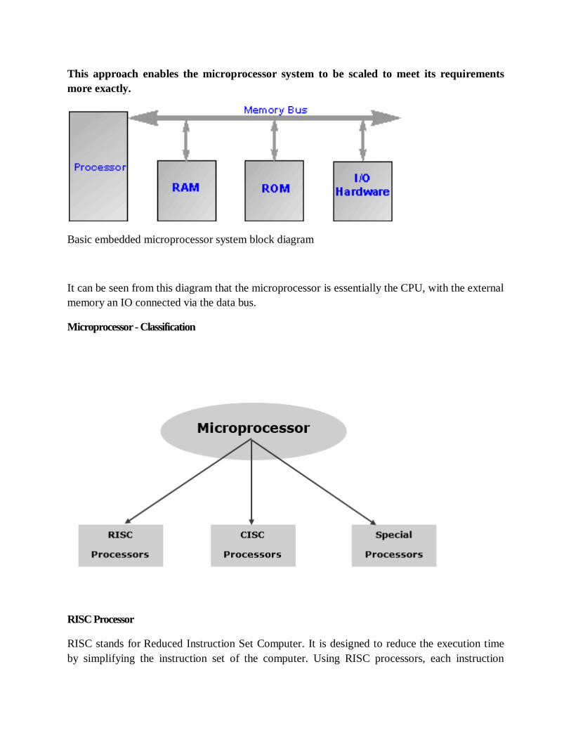
This approach enables the microprocessor system to be scaled to meet its requirements
more exactly.
Basic embedded microprocessor system block diagram
It can be seen from this diagram that the microprocessor is essentially the CPU, with the external
memory an IO connected via the data bus.
Microprocessor - Classification
RISC Processor
RISC stands for Reduced Instruction Set Computer. It is designed to reduce the execution time
by simplifying the instruction set of the computer. Using RISC processors, each instruction
Page 27
requires only one clock cycle to execute results in uniform execution time. This reduces the
efficiency as there are more lines of code, hence more RAM is needed to store the instructions.
The compiler also has to work more to convert high-level language instructions into machine
code.
Some of the RISC processors are −
Power PC: 601, 604, 615, 620
DEC Alpha: 210642, 211066, 21068, 21164
MIPS: TS (R10000) RISC Processor
PA-RISC: HP 7100LC
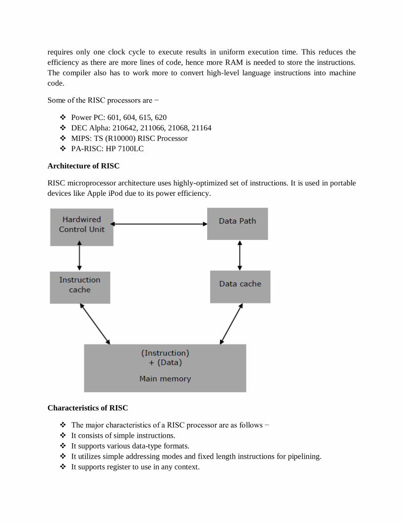
Architecture of RISC
RISC microprocessor architecture uses highly-optimized set of instructions. It is used in portable
devices like Apple iPod due to its power efficiency.
Characteristics of RISC
The major characteristics of a RISC processor are as follows −
It consists of simple instructions.
It supports various data-type formats.
It utilizes simple addressing modes and fixed length instructions for pipelining.
It supports register to use in any context.
Page 28
One cycle execution time.
“LOAD” and “STORE” instructions are used to access the memory location.
It consists of larger number of registers.
It consists of less number of transistors.
CISC Processor
CISC stands for Complex Instruction Set Computer. It is designed to minimize the number of
instructions per program, ignoring the number of cycles per instruction. The emphasis is on
building complex instructions directly into the hardware.
The compiler has to do very little work to translate a high-level language into assembly level
language/machine code because the length of the code is relatively short, so very little RAM is
required to store the instructions.
Some of the CISC Processors are −
IBM 370/168
VAX 11/780
Intel 80486
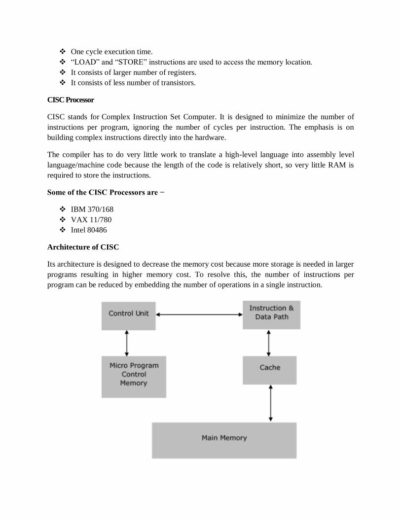
Architecture of CISC
Its architecture is designed to decrease the memory cost because more storage is needed in larger
programs resulting in higher memory cost. To resolve this, the number of instructions per
program can be reduced by embedding the number of operations in a single instruction.
Page 29
Characteristics of CISC
Variety of addressing modes.
Larger number of instructions.
Variable length of instruction formats.
Several cycles may be required to execute one instruction.
Instruction-decoding logic is complex.
One instruction is required to support multiple addressing modes.
Special Processors
These are the processors which are designed for some special purposes. Few of the special
processors are briefly discussed −
Coprocessor
A coprocessor is a specially designed microprocessor, which can handle its particular function
many times faster than the ordinary microprocessor.
For example − Math Coprocessor.
Some Intel math-coprocessors are −
8087-used with 8086
80287-used with 80286
80387-used with 80386
Input/Output Processor
It is a specially designed microprocessor having a local memory of its own, which is used to
control I/O devices with minimum CPU involvement.
For example −
DMA (direct Memory Access) controller
Keyboard/mouse controller
Graphic display controller
SCSI port controller
Transputer (Transistor Computer)
A transputer is a specially designed microprocessor with its own local memory and having links
to connect one transputer to another transputer for inter-processor communications. It was first
designed in 1980 by Inmos and is targeted to the utilization of VLSI technology
Page 30
MICROCONTROLLERS-MEMORY
There are normally 3 types of memory present in microcontrollers. These are SRAM, FLASH,
and EEPROM memories. The architecture of a microcontroller may require that variables and
constants be stored in different types of memory.
MICROCONTROLLER MEMORY TYPES
Memory types in microcontrollers Architecture
The microcontrollers units (MCUs) consist of three types of memory.
Program Memory
Data Memory
Data EEPOM
Program Memory type
This is common which have the entire microcontroller and its purposes is to store the
instructions. It consists of further four different types of memory.
ROM (Read only memory)
EPROM (Erasable programmable read only memory)
OTP (On time programmable)
FLASH EEPROM (Electrical erasable programmable read only memory)
ROM
In microcontrollers first type memory is ROM and during the manufacturing process once the
program codes are set in ROM that can’t be changed after the manufacturing process, therefore it
is called read only memory mean just read the code but can’t be changed. Due to this reason the
microcontrollers which have the ROM memory are considers best for that applications where
there is no need of program change only need of program read. These microcontrollers are less
expensive as compared to the microcontrollers which have the OTP or FLAS programmable
memory and these are ordered in large quantities.PIC16CR65 and PIC16CR72 are the examples
of microcontroller which have the ROM memory and denoted by “R” in part number.
EPROM
The second type is erasable programmable read only and this is used in two different type of
packages. When EPROM is used in ceramic package with quartz window then microcontroller
can be erased the program many times by using ultraviolet eraser and erase time depends upon
Page 31
the intensity of light. Normally the erase time is in between 5 and 30 minutes. In this the
microcontroller can also reprogrammed the program. It is very expensive due to the high cost of
windowed ceramic package.PIC16C74B/JW EPROM microcontroller are available in market
and “JW” is denoted by windowed package.
OTP
The one-time programmable memory used the same type of die as the EPROP windowed
packaged devices. Its packaging makes it unique. These microcontrollers are in an opaque plastic
packing and its program can’t be erase through ultraviolet light. The OTP devices are first
transfer to customer side then these are programmed therefore these devices are called one time
programmable. These are lowest cost devices such as PIC16C72A/P and PIC16C74B/SO are the
OTP devices
Flash EPROM
This the type which provides the alternate flexibility because its program can be erased
electrically and also reprogram in few seconds. It’s no need of any ultraviolet light to erase the
program. Once the program is erased the program can reprogram with new code. The devices
which have the flash memory can also be self-program by using some special sequence of
instructions. These devices also contain a small amount non-volatile data EPROM and that can
be written thousands of time. PIC16F77 and PIC16F877 are examples of microcontroller which
the flash memory. In these devices “F” is denoted by part number
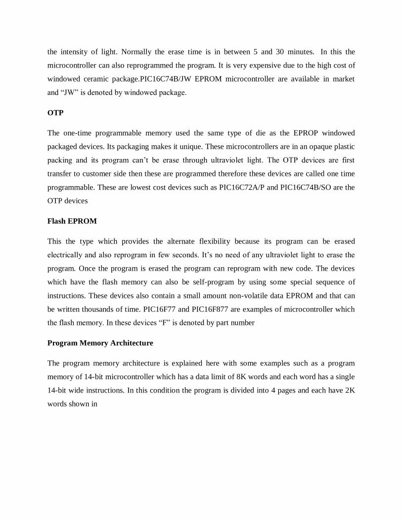
Program Memory Architecture
The program memory architecture is explained here with some examples such as a program
memory of 14-bit microcontroller which has a data limit of 8K words and each word has a single
14-bit wide instructions. In this condition the program is divided into 4 pages and each have 2K
words shown in
Page 32
figure
In this example the microcontroller uses the data memory to move the data among the pages. The
PCLATH register is used to select the next the page where the instruction would be executing.
When the CALL or GOTO instruction is executed then the PCLATH<4:3> is used to select the
page branched to. WhenPCL is modified with the user code PCLATH<4:0> then PCLATH<4:0>
is used with PCL to form the full PC address for executing the next instruction. In figure 1 you
can see the page 0 have the Reset vector at location 0 (000h). After pushing the reset, the code
starts executing at the reset vector. Usually the first two instructions set PCLATH are used for
correct program page and the third instructions that is GOTO is used for code executing in
another branch of program memory, otherwise a littler useful code can be used at the start of
program memory if the interrupts are used. During the code executing when the interrupt is
occurring then the next instruction address is fetched and saved in stack.
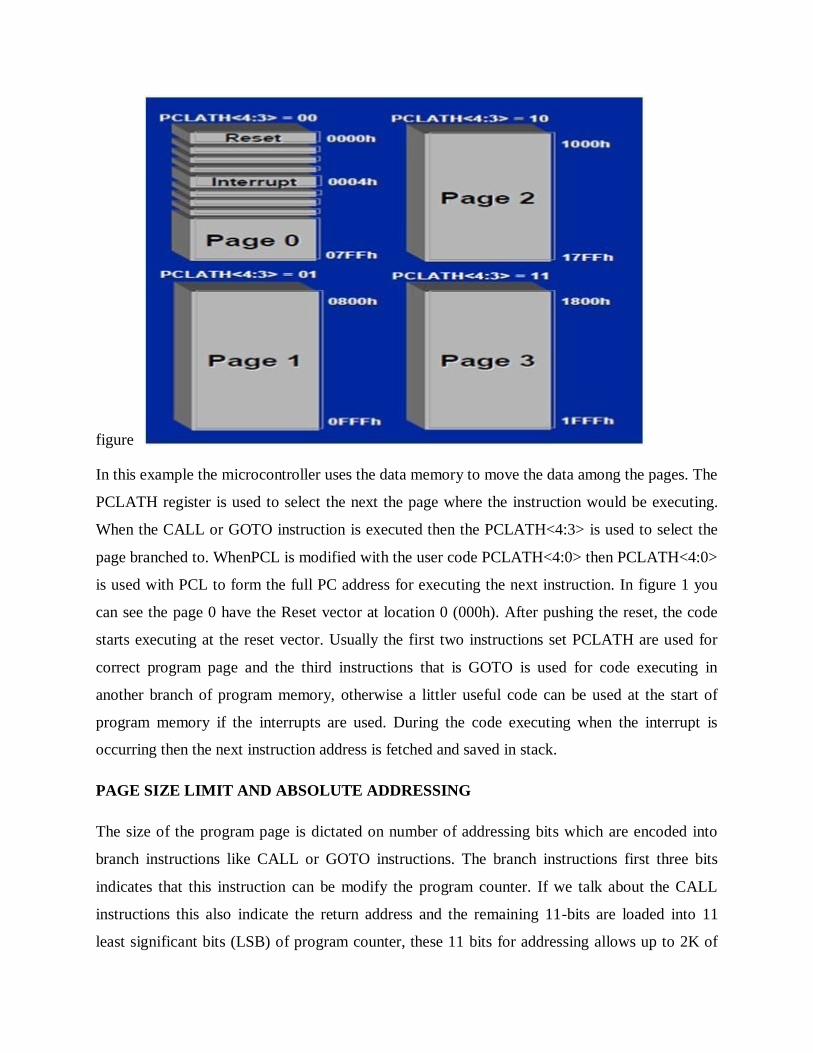
PAGE SIZE LIMIT AND ABSOLUTE ADDRESSING
The size of the program page is dictated on number of addressing bits which are encoded into
branch instructions like CALL or GOTO instructions. The branch instructions first three bits
indicates that this instruction can be modify the program counter. If we talk about the CALL
instructions this also indicate the return address and the remaining 11-bits are loaded into 11
least significant bits (LSB) of program counter, these 11 bits for addressing allows up to 2K of
Page 33
address. This defines the program memory page size and the devices which have up to 2K
program memory, the 2 most significant bit (MSB) of program counter is maintain clear for
keeping PCLATH clear. The devices which have 4K of program required 5th-bit in PCLATH for
keeping clear, while for operating in 4-bit the pages 1 or 2 are selected and the devices with 8K
of program memory required 4th and 5th-bits in PCLATH to select 1 and 4 pages. Because the
whole address is entirely defined using PCLATH and address is coded in instruction therefore
we can say we are using absolute addressing shown in figure 2 with PSLATH register.
Data Memory
This is also a common in all the microcontrollers. Its consist of general purposes registers
referred to as GPR and special function registers referred to as SPR. The data memory is
dividing into 4 banks and each banks having a length 128 bytes. For access to each bank the bits
PR1 and PR0 of status register needs to be accessed. The special function register controls the
various aspects of microcontroller depend upon the process architecture of microcontroller. It
controls the following functions of controller such as input, output and peripheral control, Timer,
program counter, stack pointer, stack limit, condition codes and processor status. The general
purpose registers store the transient type data. For example, when the program is interrupted in
Page 34
its state then that value of address register, instruction register or program counter is saved in
general purpose register.
Data EEPROM Memory
In addition of program and data memory some of the microcontrollers have third type of that is
called data EEPROM. This is nonvolatile its data can be written in many times.
Processor Architecture
Here we take a look on the microcontroller processor architecture. It controls the structure and
memory size ultimately it controls the operational speed of microcontroller. The microcontroller
has two most common architectures first one is Von Neumann architecture and second one is
Harvard architecture.
Von Neumann Architecture
The microcontrollers which have Von Neumann architecture have only a single memory space.
This single space stores both the data and program instructions. Due to this reason the several
instructions must be occur from a single memory spaces that is called fetches. The instructions
which executes again and again required a several fetches to fit in a single memory space. In this
condition first fetch retrieves the CPU instructions and the additional fetches retrieves the data,
which is required for program instruction. By doing this decreases the bandwidth of
microcontroller, because the date fetches must be wait until the program fetches instructions has
completed. This is called Von Neumann bottleneck. Shown in figure 3
Harvard Architecture
PIC microcontroller units use the Harvard architecture because these microcontrollers have
separate data and program memory. Therefore, in pic microcontroller units the fetching of
instructions and fetching of data executes simultaneously in a single fetching operation results
increased throughput. This architecture also has another advantage that it program and data bus
can be tailored with performance requirements. Its data bus is always being 8-bits wide but the
microchip offers the microcontroller, which have 12-, 14-, 16-bits program memory width.
Increasing the width allows greater no of instructions to be fetch but still the fetching operation is
in a single fetch operation
Page 35
INTRODUCTIONTOAN EMBEDDED BOARD (TMS470BASED/ARM9BASED) FOR
HANDS ON LAB SESSIONS
Virtual classroom technology is intended to replicate the…face-to-face classroom.…But one
element that's missing often is the ability for the participants to key…along with the presenter or
do practice activities on their own.…If you scroll down on your Schedule Training Session form,
notice the field for…In-session Hands-On Lab.…How this works is if you reserve computers
from the Hands-on Labs, you can allow…your participants to log in to a remote computer, not
their own computer, but log…in to a computer that has the software and activity files they'll need
to…complete their assignments during the training class.…
In order to set this up and use the Hands-on Lab, talk to your system…administrator about your
needs and what setup requirements you have.…
About Hands-on Lab Administration
Use WebEx Hands-on Lab Administration to set up and maintain the labs and computers for
Hands-on Lab sessions. With Hands-on Lab Administration you can
Create new labs
Edit existing labs
Delete labs
View lab schedules
Set up lab computers for Hands-on Lab sessions
Move computers to other labs
Remove computers from a lab
Connect to available lab computers
Disconnect from lab computers that are in session
View a computer's status
Generate Hands-on Lab usage reports
The VMware Hands-On Labs demonstrate the real value of VMware solutions in real time. As a
VM world attendee, you’ll gain special access to the latest VMware technologies without being
required to purchase equipment, software or licenses.
You’ll explore a wide range of today’s most exciting topics with a VMware-provided machine or
your own device, all with product experts on hand to provide one-on-one guidance. Earn
CloudCred points for taking labs, visiting HOL Connect and interacting with product experts,
and win prizes for each level of achievement. Join us at VMworld in Hall 6, Fira Gran Via.
Page 36
ABOUT OUR LABS
Self-Paced Labs:
This is our popular service where you can interact with the latest VMware products at your own
pace at a traditional workstation. Many product experts are in the room ready to assist. Labs are
delivered on a first-come, first-served basis and do not need to be scheduled in advance. Meet at
the check-in desk for self-paced labs in the Hall 6. Afternoons typically have no wait time
Expert-Led Workshops:
These sessions are presented by the VMware product experts who develop lab content.
Workshops require advance sign-up and check-in at least 5 minutes prior to start. The check-in
for expert-led workshops is in Hall 6. All workshop topics are available without scheduling in
the self-paced format
Hands-on Labs Tours:
These 30-minute tours provide a behind-the-scenes peek at what it takes to run our hands-on
labs. The tour covers both business and technical topics focused on VMware products and
solutions. You will meet lab creators and engineers running our multiple clouds. Sign up at the
Hands-On Labs Tour information desk in Hall 6 and engage with labs at a whole new level.
Page 37
UNIT-3
OPERATING SYSTEM IN EMBEDDED ENVIRONMENT
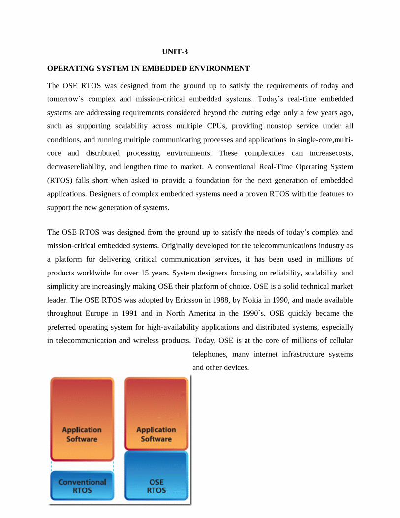
The OSE RTOS was designed from the ground up to satisfy the requirements of today and
tomorrow´s complex and mission-critical embedded systems. Today’s real-time embedded
systems are addressing requirements considered beyond the cutting edge only a few years ago,
such as supporting scalability across multiple CPUs, providing nonstop service under all
conditions, and running multiple communicating processes and applications in single-core,multi-
core and distributed processing environments. These complexities can increasecosts,
decreasereliability, and lengthen time to market. A conventional Real-Time Operating System
(RTOS) falls short when asked to provide a foundation for the next generation of embedded
applications. Designers of complex embedded systems need a proven RTOS with the features to
support the new generation of systems.
The OSE RTOS was designed from the ground up to satisfy the needs of today’s complex and
mission-critical embedded systems. Originally developed for the telecommunications industry as
a platform for delivering critical communication services, it has been used in millions of
products worldwide for over 15 years. System designers focusing on reliability, scalability, and
simplicity are increasingly making OSE their platform of choice. OSE is a solid technical market
leader. The OSE RTOS was adopted by Ericsson in 1988, by Nokia in 1990, and made available
throughout Europe in 1991 and in North America in the 1990`s. OSE quickly became the
preferred operating system for high-availability applications and distributed systems, especially
in telecommunication and wireless products. Today, OSE is at the core of millions of cellular
telephones, many internet infrastructure systems
and other devices.
Page 38
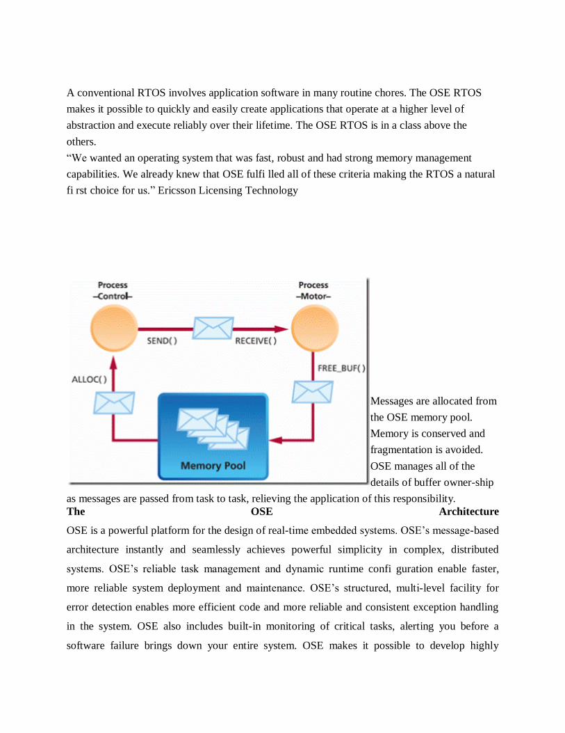
A conventional RTOS involves application software in many routine chores. The OSE RTOS
makes it possible to quickly and easily create applications that operate at a higher level of
abstraction and execute reliably over their lifetime. The OSE RTOS is in a class above the
others.
“We wanted an operating system that was fast, robust and had strong memory management
capabilities. We already knew that OSE fulfi lled all of these criteria making the RTOS a natural
fi rst choice for us.” Ericsson Licensing Technology
Messages are allocated from
the OSE memory pool.
Memory is conserved and
fragmentation is avoided.
OSE manages all of the
details of buffer owner-ship
as messages are passed from task to task, relieving the application of this responsibility.
The OSE Architecture
OSE is a powerful platform for the design of real-time embedded systems. OSE’s message-based
architecture instantly and seamlessly achieves powerful simplicity in complex, distributed
systems. OSE’s reliable task management and dynamic runtime confi guration enable faster,
more reliable system deployment and maintenance. OSE’s structured, multi-level facility for
error detection enables more efficient code and more reliable and consistent exception handling
in the system. OSE also includes built-in monitoring of critical tasks, alerting you before a
software failure brings down your entire system. OSE makes it possible to develop highly
Page 39
reliable applications in far less time. Its architecture is designed specifically to meet the
challenges of distributed and faulttolerant system designs.
At the heart of the OSE architecture is a direct message-passing model that provides fast,
asynchronous intertask communication. Message buffers are allocated from the OSE memory
pool. Memory is ecologically conserved and fragmentation is avoided. OSE manages all of the
details of buffer ownership as messages are passed from task to task, relieving the application of
this responsibility. As a result, applications interoperate much more intuitively and avoid many
of the program errors that result with other intertask communication models. This is the OSE
direct messagepassing advatage.
OSE is the Leading RTOS for Use in High-Availability Designs
OSE was designed with built-in capabilities for creating service-critical, mission-critical, and
safety-critical systems. This has always been a central design feature in OSE – not an after-
thought. For example, OSE has always supported essential concepts such as user-supervisor
modes and hardware-enabled memory protection. Rather than executing as a single task, or
multiple tasks with no inherent memory protection,
OSE enables an application to consist of a number of distributed components.
Each task can be a separate entity with its own protected resources controlled entirely by the
OSE kernel. An application written for OSE can easily be divided into logical parts, each
independently designed and coded, with communications between them transparently managed
as messages pass across protection domain boundaries. The result is high application
performance, while maintaining stability and reliability across the entire system. And OSE goes
beyond supporting these essential concepts with architecture-specific mechanisms that greatly
enhance system availability. The deeper you look into OSE and compare it to other offerings on
the market, the more you will understand why developers choose OSE when time to market and
high availability are critical.
OSE TRANSPARENTLY EXTENDS ITS MESSAGE-PASSING ACROSS CPU
BOUNDARIES
OSE can put critical tasks on a watch list and automatically notify the application, should a task
of interest be created or deleted. Applications can take action before a fault becomes a fatal error.
With OSE you design at a higher level, creating applications that are easier to write, understand,
and maintain.
Page 40
OSE HAS BUILT-IN SUPERVISION MECHANISMS FOR MONITORING CRITICAL
TASKS
Enea´s unique OSE Link Handler technology manages the transparent connection of tasks to
services regardless of their location. If one task or an entire board fails, the software can
automatically reconnect clients and their services without interruption to the application.
OSE IS UNMATCHED IN ITS ABILITY TO SUPPORT DYNAMIC SOFTWARE
RECONFIGURATION
Live software replacement is a reality with OSE. New versions of programs can be loaded onto
the system and clients can be redirected to the new instance at any time, without rebooting.
Stopping, recompiling and reloading are no longer necessary.
DESIGN ON A HIGHER LEVEL WITH OSE AND PROJECTS ARE COMPLETED
FASTER AND WITH FEWER ERRORS
Developers who use other commercial RTOS have had to dig through piles of manuals to learn
the low-level primitives found in most RTOS. OSE on the other hand provides a compact, well-
designed set of services and simple elegant APIs for those services. OSE developers find that
most applications can be managed with just eight powerful kernel APIs. With OSE you design at
a higher level, creating applications that are easier to write, understand,and maintain. This has
far-reaching benefits. Programmers learn and master OSE faster than other operating
systems, make fewer mistakes, and find errors more quickly. This shortens development time
and produces code that is more readily reused. Together with OSE’s automatic error detection
and built-in application-level debugging, these features greatly enhance productivity and quality.
OSE BUILDS IN AUTOMATIC ERROR DETECTION
OSE has an advanced, built-in error detection system. Should an error be detected, OSE
automatically invokes a user-defined error handler specific to its task, block, or system scope.
This simple-to-use, but powerful feature replaces the complex code and inconsistencies that
often result when programmers handle errors differently throughout their application tasks.
WITH OSE YOU CAN DEBUG AT THE APPLICATION LEVEL, AN EASIER PLACE
TO WORK
OSE’s modern message-based paradigm provides the basis for powerful application-level
debugging.Occurrences such as the passing of specific message types or context switching, can
be followed step by step, or traced in real-time. Breakpoints can be placed on these occurrences
Page 41
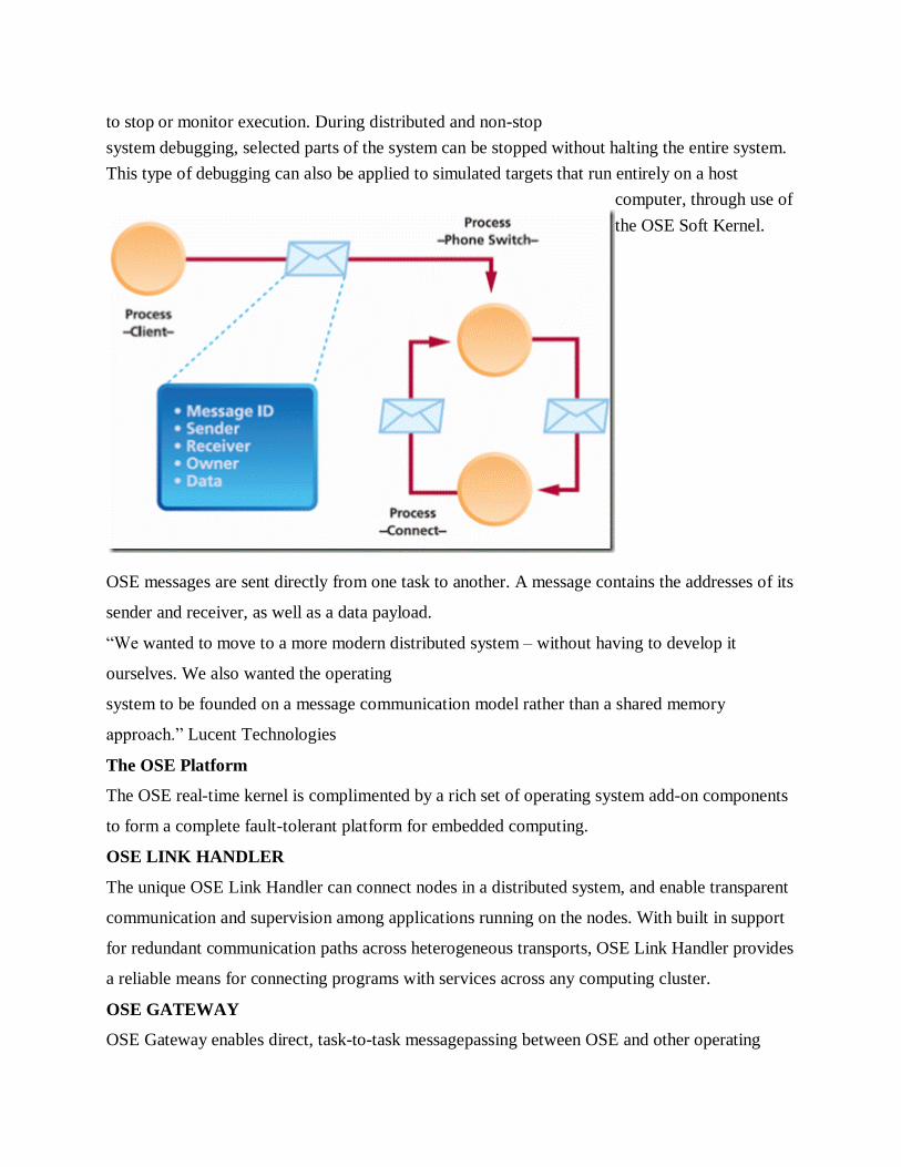
to stop or monitor execution. During distributed and non-stop
system debugging, selected parts of the system can be stopped without halting the entire system.
This type of debugging can also be applied to simulated targets that run entirely on a host
computer, through use of
the OSE Soft Kernel.
OSE messages are sent directly from one task to another. A message contains the addresses of its
sender and receiver, as well as a data payload.
“We wanted to move to a more modern distributed system – without having to develop it
ourselves. We also wanted the operating
system to be founded on a message communication model rather than a shared memory
approach.” Lucent Technologies
The OSE Platform
The OSE real-time kernel is complimented by a rich set of operating system add-on components
to form a complete fault-tolerant platform for embedded computing.
OSE LINK HANDLER
The unique OSE Link Handler can connect nodes in a distributed system, and enable transparent
communication and supervision among applications running on the nodes. With built in support
for redundant communication paths across heterogeneous transports, OSE Link Handler provides
a reliable means for connecting programs with services across any computing cluster.
OSE GATEWAY
OSE Gateway enables direct, task-to-task messagepassing between OSE and other operating
Page 42
systems. OSE Gateway supports Solaris, Windows, Linux, VxWorks, Epoc and virtually any
operating system.
EMBEDDED FILE SYSTEM
The OSE Embedded File System (EFS) can be used for storing program modules and for
transferring data to and from many types of storage devices. Designed for distributed computing,
OSE EFS is a fully distributed file system service that supports a variety of volume managers
and media types including but not limited to RAM, flash, and FAT-based
media.
NETWORKING ALLIANCES
OSE, in conjunction with best in class providers of advanced networking software, maximizes
flexibility and choice for its customers. OSE collaborates with providers of IPv4/IPv6 stacks,
management (SNMP, web based, etc), routing, security and utilities telecom protocols to deliver
leading edge solutions to the market.
OSE PROGRAM HANDLER
The OSE Program Handler is a powerful utility for systems requiring high availability as it can
load, modify, and remove programs during run-time. While many embedded platforms support
run-time loading of new programs, most fall short when system designs require live software
replacement. With the OSE Program Handler, new versions of software can replace old ones
without interrupting the application’s execution.
OSE BOARD SUPPORT PACKAGES
The OSE Board Support Packages (BSP) provide support for the latest standard boards from
many suppliers.BSP drivers conform to the OSE device-driver specification, allowing seamless
migration from board to board.
OSE MEMORY MANAGEMENT SYSTEM
The OSE Memory Management System (MMS) isolates and protects functional software units
from one another and also protects the kernel from application software errors. The OSE MMS
design is optimized for embedded systems with a flexible and high performance implementation.
Page 43
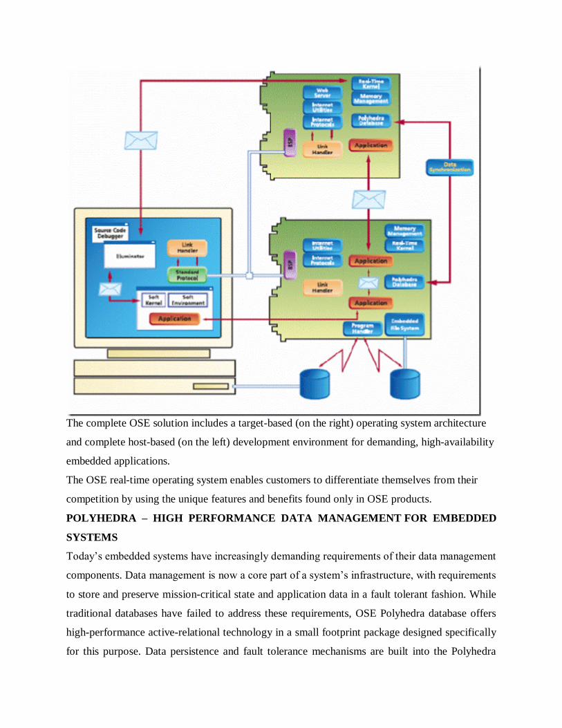
The complete OSE solution includes a target-based (on the right) operating system architecture
and complete host-based (on the left) development environment for demanding, high-availability
embedded applications.
The OSE real-time operating system enables customers to differentiate themselves from their
competition by using the unique features and benefits found only in OSE products.
POLYHEDRA – HIGH PERFORMANCE DATA MANAGEMENT FOR EMBEDDED
SYSTEMS
Today’s embedded systems have increasingly demanding requirements of their data management
components. Data management is now a core part of a system’s infrastructure, with requirements
to store and preserve mission-critical state and application data in a fault tolerant fashion. While
traditional databases have failed to address these requirements, OSE Polyhedra database offers
high-performance active-relational technology in a small footprint package designed specifically
for this purpose. Data persistence and fault tolerance mechanisms are built into the Polyhedra
Page 44
database, ensuring survival of the database service across failure of part of the system, and robust
data recovery in the event of a restart. Polyhedra’s unique active-relational technology provides
the ability to encode application logic such as data integrity rules, directly into the database; and
“Active
Queries”, enabling immediate notification to applications of data change. The Polyhedral
database is integrated with the OSE RTOS, using OSE messaging for communication between
applications and the database server, and operates seamlessly regardless of the physical location
of the tasks. The database also connects to other embedded systems, servers, or workstations
over TCP/IP – while automatically handling heterogeneity issues, making database location
transparent to the developer.
Superior Tools for Rapid Development
providing a modern and robust architecture for today’s complex embedded systems is only half
of the story. Developing reliable applications that take advantage of the features of the OSE
RTOS is faster and less error prone than with a traditional RTOS, thanks to a powerful chain of
OSE tools. This tool chain consists of industry-standard compilers and debuggers, powerful host-
target tools, and accurate simulators, all supported by a comprehensive, integrated development
and debugging environment.
OSE ILLUMINATOR
OSE Illuminator is a host-based suite of software tools for debugging and analyzing OSE
applications. OSE Illuminator includes a system browser, an event-action analyser, and profiling
tools. It can also integrate a variety of plug-in
tools that provide additional debugging capability and system information. Illuminator also
communicates with target boards through standard TCP/IP communication protocols and
interconnects with source-level debuggers.
SOFT KERNEL
OSE Soft Kernel makes it possible to simulate your application on host computers. OSE Soft
Kernel can simulate part of a system, a whole system, or even a distributed system including a
mix of actual hardware boards and multiple OSE Soft Kernels, before moving all software to its
final target.
Page 45
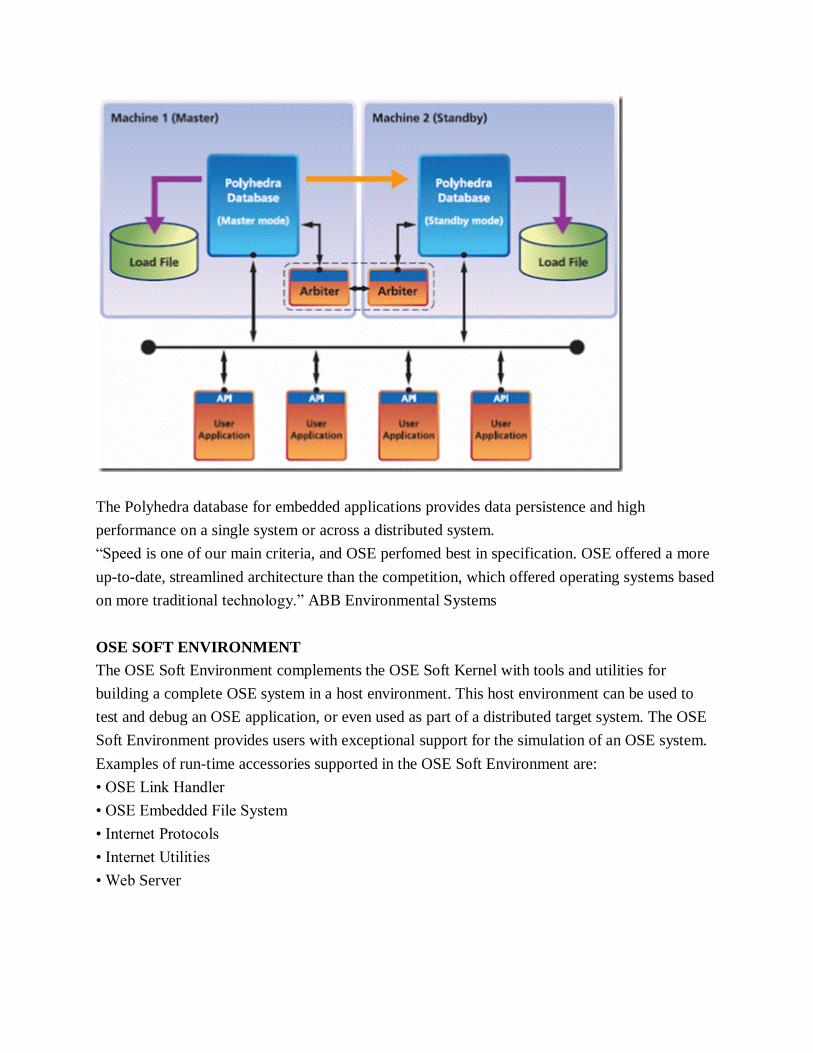
The Polyhedra database for embedded applications provides data persistence and high
performance on a single system or across a distributed system.
“Speed is one of our main criteria, and OSE perfomed best in specification. OSE offered a more
up-to-date, streamlined architecture than the competition, which offered operating systems based
on more traditional technology.” ABB Environmental Systems
OSE SOFT ENVIRONMENT
The OSE Soft Environment complements the OSE Soft Kernel with tools and utilities for
building a complete OSE system in a host environment. This host environment can be used to
test and debug an OSE application, or even used as part of a distributed target system. The OSE
Soft Environment provides users with exceptional support for the simulation of an OSE system.
Examples of run-time accessories supported in the OSE Soft Environment are:
• OSE Link Handler
• OSE Embedded File System
• Internet Protocols
• Internet Utilities
• Web Server
Page 46
OSE – A Complete Solution
The OSE RTOS provides a complete framework for the implementation of ultra-reliable and
ultra-efficient real-time systems -from resource constrained single CPU systems to large,
distributed systems. OSE includes a full suite of software development tools for building and
deploying complex, mission-critical embedded systems. In addition, a full suite of simulation
development components and tools allow an OSE system to run in a host environment -ideal for
parallel software-hardware development. The OSE host system may also be connected to a target
system for debugging, or the host system may be a part of a deployed distributed system. It is the
powerful, distributed architecture of OSE combined with its higher level, dynamic design
paradigm of message passing and it’s built in mechanisms for fault tolerance and high
availability that make OSE the clear platform choice for today’s modern embedded des.
Page 47
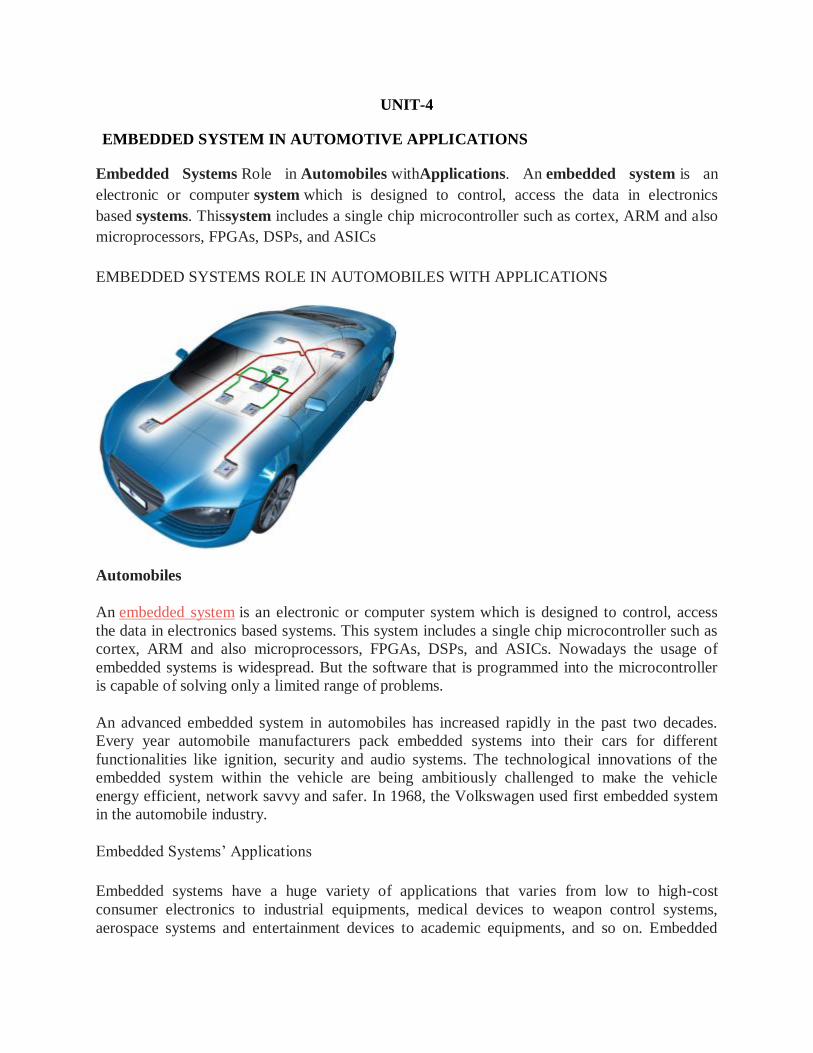
UNIT-4
EMBEDDED SYSTEM IN AUTOMOTIVE APPLICATIONS
Embedded Systems Role in Automobiles withApplications. An embedded system is an
electronic or computer system which is designed to control, access the data in electronics
based systems. Thissystem includes a single chip microcontroller such as cortex, ARM and also
microprocessors, FPGAs, DSPs, and ASICs
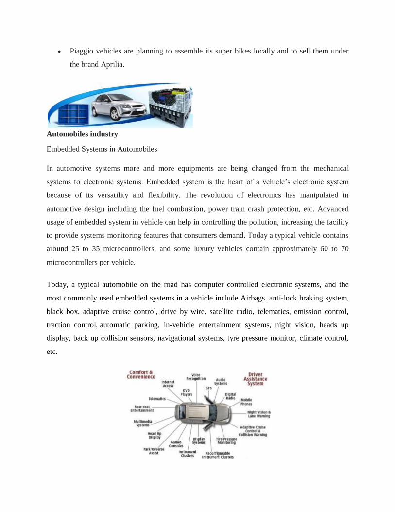
EMBEDDED SYSTEMS ROLE IN AUTOMOBILES WITH APPLICATIONS
Automobiles
An embedded system is an electronic or computer system which is designed to control, access
the data in electronics based systems. This system includes a single chip microcontroller such as
cortex, ARM and also microprocessors, FPGAs, DSPs, and ASICs. Nowadays the usage of
embedded systems is widespread. But the software that is programmed into the microcontroller
is capable of solving only a limited range of problems.
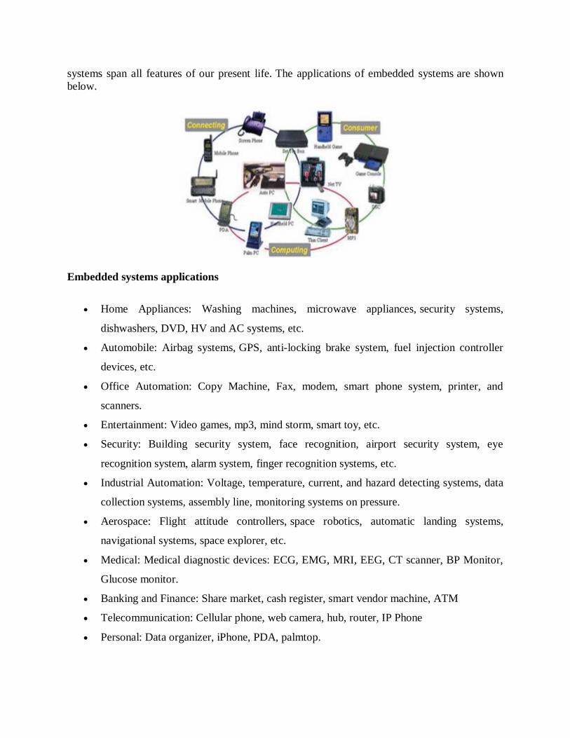
An advanced embedded system in automobiles has increased rapidly in the past two decades.
Every year automobile manufacturers pack embedded systems into their cars for different
functionalities like ignition, security and audio systems. The technological innovations of the
embedded system within the vehicle are being ambitiously challenged to make the vehicle
energy efficient, network savvy and safer. In 1968, the Volkswagen used first embedded system
in the automobile industry.
Embedded Systems’ Applications
Embedded systems have a huge variety of applications that varies from low to high-cost
consumer electronics to industrial equipments, medical devices to weapon control systems,
aerospace systems and entertainment devices to academic equipments, and so on. Embedded
Page 48
systems span all features of our present life. The applications of embedded systems are shown
below.
Embedded systems applications
Home Appliances: Washing machines, microwave appliances, security systems,
dishwashers, DVD, HV and AC systems, etc.
Automobile: Airbag systems, GPS, anti-locking brake system, fuel injection controller
devices, etc.
Office Automation: Copy Machine, Fax, modem, smart phone system, printer, and
scanners.
Entertainment: Video games, mp3, mind storm, smart toy, etc.
Security: Building security system, face recognition, airport security system, eye
recognition system, alarm system, finger recognition systems, etc.
Industrial Automation: Voltage, temperature, current, and hazard detecting systems, data
collection systems, assembly line, monitoring systems on pressure.
Aerospace: Flight attitude controllers, space robotics, automatic landing systems,
navigational systems, space explorer, etc.
Medical: Medical diagnostic devices: ECG, EMG, MRI, EEG, CT scanner, BP Monitor,
Glucose monitor.
Banking and Finance: Share market, cash register, smart vendor machine, ATM
Telecommunication: Cellular phone, web camera, hub, router, IP Phone
Personal: Data organizer, iPhone, PDA, palmtop.
Page 49
Introduction to Automobiles Industry
As far as automobile industry is concerned, a wide range of industries and companies are
involved in the development, designing manufacturing and selling of cars, bikes, buses, etc. India
represents one of the world’s largest automobile markets. From the past few years, even the
middle-class has started showing interest in buying a vast range of cars or vehicles. The growth
of the Indian automobile industry has recorded tremendous potential over the years.
The industry’s financial record is almost 7% of the country’s gross domestic product and both
directly or indirectly, automobile industry employs about 19 million people. Moreover, with the
government support and a special focus on exports of two and three wheelers, small cars, auto
components and multi-utility vehicles, the automobile industry produced 1.73 million vehicles in
February 2013 alone including commercial, two wheeler and three wheeler vehicles and
passenger vehicles as well. In February 2014, the industry produced 1.81 million vehicles.
Government proposals
The budget of 2014-2015 added some incentives to the automobile industries to give
relief. The excise duty that has got decreased till June 30, 2014 is as follows:
For motor cycles, scooters and small cars the duty has been decreased from the current
12% to 8%.
For SUVs and Commercial vehicles the duty has been decreased from 30% to 24%.
For large cars the duty has been decreased from 27/24% to 24/20%.
Major Investments
The German auto maker Volkswagen is planning to enlarge production capacity and
introduce a new model. To set up a diesel engine manufacturing facility, the group is
planning to invest around Rs. 1500 crores over the next five years.
To buy the Germany’s Kuepper Group of companies, Amtek Auto has signed an
agreement of Rs 16.78 billion.
Infosys has signed a contract with the Volvo cars to provide application development
services.
Page 50
Piaggio vehicles are planning to assemble its super bikes locally and to sell them under
the brand Aprilia.
Automobiles industry
Embedded Systems in Automobiles
In automotive systems more and more equipments are being changed from the mechanical
systems to electronic systems. Embedded system is the heart of a vehicle’s electronic system
because of its versatility and flexibility. The revolution of electronics has manipulated in
automotive design including the fuel combustion, power train crash protection, etc. Advanced
usage of embedded system in vehicle can help in controlling the pollution, increasing the facility
to provide systems monitoring features that consumers demand. Today a typical vehicle contains
around 25 to 35 microcontrollers, and some luxury vehicles contain approximately 60 to 70
microcontrollers per vehicle.
Today, a typical automobile on the road has computer controlled electronic systems, and the
most commonly used embedded systems in a vehicle include Airbags, anti-lock braking system,
black box, adaptive cruise control, drive by wire, satellite radio, telematics, emission control,
traction control, automatic parking, in-vehicle entertainment systems, night vision, heads up
display, back up collision sensors, navigational systems, tyre pressure monitor, climate control,
etc.
Page 51
Embedded System in Automobiles
1. Embedded Airbag System
The below figure shows an embedded airbag system – an important safety device that provides
extra protection against head-on crash – for the front seat occupants. This System works on the
commands from the microcontroller. The controller of this system gets the power from the
battery. If the sensors detect accident, this microcontroller operates the airbag system by
operating alternator.
Embedded Airbag System
Automobile Navigation System
2. Embedded Navigation System
Another advancement of the embedded system in automobiles is the navigational system using
GPS system. This navigational system consists of an embedded circuitry built with a GPS
receiver, a gyroscope, a DVD-ROM, main controller and a display system as shown in the
figure. The GPS receiver receives the current longitude and latitude values that are compared
with the stored map. The Gyroscope and other sensors provide the road direction and speed.
Page 52
From all the information gathered at the main controller, the display system displays a navigation
or route map of the destination in the display screen.
Embedded Navigational System
3. Adaptive Cruise Control
The innovation of the embedded system used in automobiles is Adaptive cruise Control
technology. By using this technology we can also make driverless vehicle control in a reality and
many automobile manufacturers are also already engaged in work on these concepts. This
adaptive cruise control allows cars to keep safe distances from other vehicles on the busy
highway roads. The driver of the car can set the speed of his vehicle and the distance between his
car and other vehicles. When the traffic slows down, ACC changes vehicle speed using moderate
braking.
Page 53
Adaptive Cruise Control
Each car has a laser transceiver or a microwave radar unit which is fixed in front of the car to
find out the speed and distance of the any other vehicle in the pathway. This is works on the
principle of Doppler Effect; it is nothing but change in frequency of the waves.
4. Embedded Rain-Sensing System
Embedded rain-sensing system
Embedded rain-sensing system in automobiles is another automation system implemented with
use of electronic system. In this, an optical sensor is placed on small area of the front windshield
glass (opposite to rear-view mirror). This optical sensor is placed at an angle to emit the infrared
light which then reads amount of light by it when the light is reflected back. This light is
reflected in cases where the windshield is wet or dirty. Thus the optical sensor determines
necessary speed and frequency of windshield wiper depends on reflected light into the sensor.
5. Embedded Based Automatic Parking System
Page 54
Embedded Based Automatic Parking System
This automatic parking system is an independent car manipulation system that moves a car from
traffic lane into a parking spot to perform the parallel parking, perpendicular parking and angle
parking. This system mainly uses different methods to detect objects around the car. Sensors
installed on the front of the vehicle and rear bumpers acts as both a transmitter and a receiver.
These sensors send a signal that will be replicated back when it meets an obstacle near the
vehicle, and then the carputer will receives the time signal and bumper will use the radar to
decide the position of the obstacle. The car will sense the parking space and distance from the
side of the road then drive the car into the parking place.
Thus, the modern days embedded systems have marked a revolutionary change in every aspect
of the automobile designing and manufacturing processes because of their adaptability and
flexibility. Now the question is: Have you got the basic concept of embedded systems in
automobiles? If you have got some basic understanding of this concept with a little bit of doubt
on this topic, you can give your feedback and suggestions in the comment section below, and let
us know how would you like to get some help or assistance from us.
SOFTWARE CALIBRATION USING ENGINE AND VEHICLE DYNAMOMETERS
ENGINE DYNAMOMETERS
Power Test water brake engine dynamometers excel at testing wide ranges of power inputs with
one dynamometer. Engine dynamometers are used to test engines removed from the vehicle. We
offer several configurations for different dyno test applications.
The H36-Series engine dynamometer is specifically designed to handle the high torque output of
engines found in the mining, power generation and marine propulsion industries. This series has
power absorption capabilities of up to 50,000 ft-lbs of torque and up to 10,000HP.
Our X-Series fixed base dynamometer may be used for continuous-duty endurance dyno tests,
break-in and power verification, quality assurance tests and demanding research and
development tests such as transient emissions testing. Our engine carts offer the flexibility of
moving an engine within your facility, and ensure quick, precise placement to our sub bases.
Our portable water brake dynamometers connect directly to the flywheel to allow engine dyno
testing in facilities with limited space.
Page 55
In addition to water brake engine dynamometers, Power Test has Eddy Current engine
dynamometers. The Power Test EC-Series of engine dynamometers feature in-line eddy current
absorption units in a robust compact frame. They may be used for continuous-duty engine power
verification, quality assurance, endurance and certification testing.
AGRICULTURAL DYNAMOMETERS FOR PTO OUTPUT
The AG-Series agricultural dynamometer system features air-cooled eddy current dynamometer
absorbers designed to meet your demand for reliable, portable PTO testing. This results in lower
maintenance costs for you and fewer reliability issues than those normally associated with
agricultural dynamometers that typically rely on a friction brake or hydraulic pump design.
The AG-Series dynamometer is supplied to you with the Digital Power Meter (DPM) with
remote load control and PC interface featuring the DPM Data Logger software. Also available to
you is our popular Power Net LT Data Acquisition and Control System, and a variety of drive
shafts and adapters to fit most applications.
Specifications
HP: up to 250 HP Continuous
Speed: 2,600 RPM Max.
Weight: est. 3,500 lbs.
CUSTOM ENGINEERED SOLUTIONS
In addition to Power Test’s wide variety of standard equipment, many non-standard powertrain
test requirements demand sophisticated engineered solutions.
This is why Power Test formed its Custom Engineered Solutions division. This team utilizes
Power Test’s industry-leading engineering expertise to create a solution to fit any unique
application. The Engineered Solutions team studies all aspects of the test requirement to
determine the optimized test solution. The concept is taken by the team of mechanical and
electrical engineers to create a new machine design. CAD designers develop solid models of the
new test stand for customer review and approval prior to release to our manufacturing operations
group, where the testing solution is custom-built.
ENVIRONMENTAL TESTS FOR ELECTRONIC CONTROL UNITS.
In automotive electronics, Electronic Control Unit (ECU) is any embedded system that
controls one or more of the electrical system or subsystems in a transport vehicle.
Types of ECU include Electronic/engine Control Module (ECM), Powertrain Control
Module (PCM), Transmission Control Module (TCM), Brake Control Module (BCM or EBCM),
Central Control Module (CCM), Central Timing Module (CTM), General Electronic Module
Page 56
(GEM), Body Control Module (BCM), Suspension Control Module (SCM), control unit, or
control module. Taken together, these systems are sometimes referred to as the car's computer
(Technically there is no single computer but multiple ones.) Sometimes one assembly
incorporates several of the individual control modules (PCM is often both engine and
transmission).
Some modern motor vehicles have up to 80 ECUs. Embedded software in ECUs continues to
increase in line count, complexity, and sophistication.[2]
Managing the increasing complexity and
number of ECUs in a vehicle has become a key challenge for original equipment
manufacturers (OEMs). Examples of such ECUs include:
Door control unit (DCU)
Engine control unit (ECU) — not to be confused with electronic control unit, the generic
term for all these devices
Electric Power Steering Control Unit (PSCU) — Generally this will be integrated into
the EPS powerpack.
Human-machine interface (HMI)
Powertrain control module (PCM): Sometimes the functions of the Engine Control
Unit and transmission control unit (TCU) are combined into a single unit called the
Powertrain Control Module.
Seat Control Unit
Speed control unit (SCU)
Telematic control unit (TCU)
Transmission control unit (TCU)
Brake Control Module (BCM; ABS or ESC)
Battery management system
KEY ELEMENTS OF ECU
Core
Microcontroller
Memory
SRAM
EEPROM
Flash
Inputs
Supply Voltage
Digital inputs
Analog inputs
Outputs
Relay drivers
H bridge drivers
Injector drivers
Logic outputs
Page 57
Communication links
Housing
DESIGN AND DEVELOPMENT
The development of an ECU involves both hardware and software required to perform the
functions expected from that particular module. Automotive ECU's are being developed
following the V-model.[1]
Recently the trend is to dedicate a significant amount of time and effort
to develop safe modules by following standards like ISO 26262.[3]
It is rare that a module is
developed fully from scratch. The design is generally iterative and improvements are made to
both the hardware and software. The development of most ECU's are carried out by Tier 1
suppliers based on specifications provided by the OEM.
TESTING AND VALIDATING
As part of the development cycle, manufacturers perform detailed FMEAs and other failure
analyses to catch failure modes that can lead to unsafe conditions or driver annoyance. Extensive
testing and validation activities are carried out as part of the Production part approval process to
gain confidence of the hardware and software. On-board diagnostics or OBD help provide
specific data related to which system or component failed or caused a failure during run time and
help perform repairs.
TUNING
Some people are eager to modify their ECU so as to be able to add more functionality to it. Most
ECU's these days however come equipped with protection locks which prevent users of
modifying the ECU. The protection locks are made in a way that, when circumvented,
triggers DMCA liability. This in effect makes modifying the ECU by circumventing the
protection illegal.[4]
Page 58
UNIT-5
EMBEDDED SYSTEM COMMUNICATION PROTOCOLS
Introduction t o Control n e t w o r k i n g
An industrial control network is a system of interconnected equipment used to monitor and
control physical equipment in industrial environments. These networks differ quite significantly
from traditional enterprise networks due to the specific requirements of their operation. Despite
the functional differences between industrial and enterprise networks, a growing integration
between the two has been observed. The technology in use in industrial networks is also
beginning to display a greater reliance on Ethernet and web standards, especially at higher levels
of the network architecture. This has resulted in a situation where engineers involved in the
design and maintenance of control networks must be familiar with both traditional enterprise
concerns, such as network security, as well as traditional industrial concerns such as determinism
and response time. This paper highlights some of the differences between enterprise and
industrial networks, presents a brief history of industrial networking, gives a high level
explanation of some operations specific to industrial networks, provides an overview of the
popular protocols in use and describes current research topics. The purpose of this paper is to
serve as an introduction to industrial control networks, aimed specifically at those who have had
minimal exposure to the field, but have some familiarity with conventional computer networks.
EMBEDDED SYSTEM COMMUNICATION PROTOCOLS
This is a list of common protocols used in embedded systems. Eventually, this list will become
hyperlinks to sources of information on each. Many of them are byte-stream protocols that can
be transmitted by a variety of serial protocols on a variety of hardware.
I2C
RS-485 is an extremely common hardware arrangement used by many embedded protocols:
CAN on top of RS485
DeviceNet on top of CAN. Wikipedia: DeviceNet
NMEA 2000 on top of DeviceNet. Wikipedia: NMEA 2000
Page 59
DMX on top of RS485. Wikipedia: DMX512
see Serial Programming/RS-485, Robotics/Computer Control/The
Interface/Networks#RS485, Embedded Control Systems Design/Field busses, Embedded
Systems/Serial and Parallel IO#RS-485
MIDI. official MIDI interface schematics (1); beautiful MIDI IN schematic (2).
BlueTooth
InfraRed
ZigBee
SPI
RS-232
USB
IP Over Serial Connections
MINES (Microcontroller Interpreter for Networked Embedded Systems) was designed for
very small embedded systems (see Gallery of MINES Devices).
the Tiny Embedded Network
IEEE Standard for Sensor Transducer Interface
the three byte Mini SSC protocol (and another Mini SSC protocol example)
JTAG
NTSC / PAL television video output: w:TV Typewriter, Generating TV signal by
PSoC, Generating TV signal with the PICs, PIC Breakout, ... Parallax Propeller has a video
generator ...
The low-latency Myrinet protocol is used in over 100 of the TOP500 supercomputers, as of
June 2005.
The low-latency InfiniBand protocol is used in over 100 of the TOP500 supercomputers, as
of November 2010.
The various Audio over Ethernet (AoE) protocols are generally designed to be relatively low
latency.
The LIN-Bus (w:Local Interconnect Network), a low-cost vehicle communication network
Modbus (w:Modbus)
Page 60
Firmata is a generic protocol that allows people to completely control the Arduino from
software on a host computer. Arduino reference for Firmata; Firmata wiki.
rosserial "rosserial ... is a general protocol for sending ROS messages over serial links."
Code is available for Arduino and a variety of other platforms. (It was designed for ROS,
the w: Robot Operating System).
S.N.A.P - Scaleable Node Address Protocol [1] is media-independent, building on an
underlying byte-oriented communication layer.
Yet Another Scalable Protocol (YASP)
Labor-Octet-Protocol (LOP) is a simple protocol originally implemented on AVR
microcontrollers; it builds on an underlying byte-oriented communication layer and provides
support for both message-oriented (all-or-nothing) and stream-oriented communication.
Inter-Chip Serial Communications (ICSC) is a simple, high-reliability media-independent
protocol originally implemented on Arduino.
Perhaps the simplest-to-parse variable-size packet container format is the netstring
format.w:netstring
JSON (perhaps encapsulated in packets of one of the above formats) seems to be gaining
popularity as a way to transmit complex data structures, in a way that is easy for humans to
read and debug.[2] w:JSON
Serial Peripheral Interface Bus
Single Master to Single Slave: basic SPI bus example.
The Serial Peripheral Interface bus (SPI) is a synchronous serial communication interface
specification used for short distance communication, primarily in embedded systems. The
interface was developed by Motorola in the late 1980s and has become a de facto standard.
Typical applications include Secure Digital cards and liquid crystal displays.
Page 61
SPI devices communicate in full duplex mode using a master-slave architecture with a single
master. The master device originates the frame for reading and writing. Multiple slave devices
are supported through selection with individual slave select (SS) lines.
Sometimes SPI is called a four-wire serial bus, contrasting with three-, two-, and one-wire serial
buses. The SPI may be accurately described as a synchronous serial interface,[1]
but it is different
from the Synchronous Serial Interface (SSI) protocol, which is also a four-wire synchronous
serial communication protocol. SSI Protocol employs differential signaling and provides only a
single simplex communication channel.
Independent slave configuration
Typical SPI bus: master and three independent slaves
In the independent slave configuration, there is an independent chip select line for each slave. A
pull-up resistor between power source and chip select line is highly recommended for each
independent device to reduce cross-talk between devices.[3]
This is the way SPI is normally used.
Since the MISO pins of the slaves are connected together, they are required to be tri-state pins
(high, low or high-impedance).
Daisy chain configuration]
Daisy-chained SPI bus: master and cooperative slaves
Page 62
Some products that implement SPI may be connected in a daisy chain configuration, the first
slave output being connected to the second slave input, etc. The SPI port of each slave is
designed to send out during the second group of clock pulses an exact copy of the data it
received during the first group of clock pulses. The whole chain acts as a communication shift
register; daisy chaining is often done with shift registers to provide a bank of inputs or outputs
through SPI. Such a feature only requires a single SS line from the master, rather than a separate
SS line for each slave.[4]
Applications that require a daisy chain configuration include SGPIO and JTAG.
Valid communications
Some slave devices are designed to ignore any SPI communications in which the number of
clock pulses is greater than specified. Others do not care, ignoring extra inputs and continuing to
shift the same output bit. It is common for different devices to use SPI communications with
different lengths, as, for example, when SPI is used to access the scan chain of a digital IC by
issuing a command word of one size (perhaps 32 bits) and then getting a response of a different
size (perhaps 153 bits, one for each pin in that scan chain).
Interrupts
SPI devices sometimes use another signal line to send an interrupt signal to a host CPU.
Examples include pen-down interrupts from touchscreen sensors, thermal limit alerts from
temperature sensors, alarms issued by real time clock chips, SDIO,[5]
and headset jack insertions
from the sound codec in a cell phone. Interrupts are not covered by the SPI standard; their usage
is neither forbidden nor specified by the standard.
Example of bit-banging the master protocol
Below is an example of bit-banging the SPI protocol as an SPI master with CPOL=0, CPHA=0,
and eight bits per transfer. The example is written in the C programming language. Because this
is CPOL=0 the clock must be pulled low before the chip select is activated. The chip select line
must be activated, which normally means being toggled low, for the peripheral before the start of
the transfer, and then deactivated afterward. Most peripherals allow or require several transfers
while the select line is low; this routine might be called several times before deselecting the chip.
Page 63
I²C
I²C (Inter-Integrated Circuit), pronounced I-squared-C or I-two-C, is a multi-master, multi-
slave, packet switched, single-ended, serialcomputer bus invented by Philips
Semiconductor (now NXP Semiconductors). It is typically used for attaching lower-speed
peripheral ICs to processors and microcontrollers in short-distance, intra-board communication.
Alternatively I²C is spelled I2C (pronounced I-two-C) or IIC (pronounced I-I-C).
Since October 10, 2006, no licensing fees are required to implement the I²C protocol. However,
fees are required to obtain I²C slave addresses allocated by NXP.[1]
Several competitors, such as Siemens AG (later Infineon Technologies AG, now Intel mobile
communications), NEC, Texas Instruments, STMicroelectronics (formerly SGS-Thomson),
Motorola (later Freescale, now merged with NXP[2]
), Nordic Semiconductor and Intersil, have
introduced compatible I²C products to the market since the mid-1990s.
SMBus, defined by Intel in 1995, is a subset of I²C, defining a stricter usage. One purpose of
SMBus is to promote robustness and interoperability. Accordingly, modern I²C systems
incorporate some policies and rules from SMBus, sometimes supporting both I²C and SMBus,
requiring only minimal reconfiguration either by commanding or output pin use.
Design
An example schematic with one master (a microcontroller), three slave nodes (an ADC, a DAC,
and a microcontroller), and pull-up resistorsRp
I²C uses only two bidirectional open-drain lines, Serial Data Line (SDL) and Serial Clock Line
(SCL), pulled up with resistors. Typical voltages used are +5 V or +3.3 V, although systems with
other voltages are permitted.
The I²C reference design has a 7-bit or a 10-bit (depending on the device used) address
space.[4]
Common I²C bus speeds are the 100 kbit/sstandard mode and the 10 kbit/s low-speed
mode, but arbitrarily low clock frequencies are also allowed. Recent revisions of I²C can host
Page 64
more nodes and run at faster speeds (400 kbit/s Fast mode, 1 Mbit/s Fast mode plus or Fm+, and
3.4 Mbit/s High Speed mode). These speeds are more widely used on embedded systems than on
PCs. There are also other features, such as 16-bit addressing.
Note the bit rates are quoted for the transactions between master and slave without clock
stretching or other hardware overhead. Protocol overheads include a slave address and perhaps a
register address within the slave device, as well as per-byte ACK/NACK bits. Thus the actual
transfer rate of user data is lower than those peak bit rates alone would imply. For example, if
each interaction with a slave inefficiently allows only 1 byte of data to be transferred, the data
rate will be less than half the peak bit rate.
The maximal number of nodes is limited by the address space and also by the total
bus capacitance of 400 pF, which restricts practical communication distances to a few meters.
The relatively high impedance and low noise immunity requires a common ground potential,
which again restricts practical use to communication within the same PC board or small system
of boards.
USB
Just about any computer that you buy today comes with one or more Universal Serial
Bus connectors. These USB connectors let you attach mice, printers and other accessories to
your computer quickly and easily. The operating system supports USB as well, so the installation
of the device drivers is quick and easy, too. Compared to other ways of connecting devices to
your computer (including parallel ports, serial ports and special cards that you install inside the
computer's case), USB devices are incredibly simple.
In this article, we'll look at USB ports from both a user and a technical standpoint. You'll learn
why the USB system is so flexible and how it's able to support so many devices so easily -- it's
truly an amazing system.
Page 65
CAN bus
A Controller Area Network (CAN bus) is a robust vehicle bus standard designed to
allow microcontrollers and devices to communicate with each other in applications without
a host computer. It is a message-based protocol, designed originally for multiplex electrical
wiring within automobiles to save on copper, but is also used in many other contexts.
Introduction to the LIN bus
Background
The protocol for the Local Interconnect Network (LIN) is based on the Volcano-Lite technology
developed by the Volvo spin-out company Volcano Communications Technology (VCT). Since
other car corporations also were interested in a more cost effective alternative to CAN, the LIN
syndicate was created. In the middle of 1999 the first LIN protocol (1.0) was released by this
syndicate. The protocol was updated twice in 2000. In November 2002 LIN 1.3 was released
with changes mainly made in the physical layer. The latest version LIN 2.0 was released in 2003.
With LIN 2.0 came some major changes and also some new features like diagnostics. The
changes were mainly aimed at simplifying use of off-the-shelves slave nodes.
Areas of use
The LIN protocol is a compliment to the CAN and the SAE J1850 protocols for applications that
are not time critical or does not need extreme fault tolerance, since LIN is not quite as reliable as
CAN. The aim of LIN is to be easy to use and a more cost effective alternative to CAN.
Examples of areas where LIN is and can be used in a car: window lift, mirrors, wiper and rain
sensors.
Page 66
Learning Module FlexRay
1/32
FlexRay is a serial communication technology that is used in particular for data communication
in very safety-critical use areas in the automobile.
This E-Learning module is intended for all those who wish to gain a better understanding of
FlexRay communication technology.
This E-Learning module is also ideal for those planning to participate in the FlexRay workshop
of the VectorAcademy. It lets you learn about the basic properties of data communications in a
FlexRay network in advance of the workshop. This not only simplifies your entry into the
workshop. Much of what you have acquired by E-Learning will be revisited in the workshop,
and this reinforces what you have already learned.
Motivation for MOST
Automobiles have evolved from having a simple radio with perhaps a cassette or CD player to
having a variety of sophisticated entertainment and information systems that need to
communicate and interact with each other and with a human user. As a matter of fact, automotive
systems are more feature-rich than many other A/V applications such as home A/V distribution,
security A/V systems and industrial applications. MOST offers an optimized architecture for the
real-time transport of audio, video, data and control. It is the backbone of modern infotainment
systems.
Page 67
Keyword Protocol 2000
Keyword Protocol 2000, abbreviated KWP2000, is a communications protocol used for on-
board vehicle diagnostics systems (OBD). This protocol covers the application layer in the OSI
model of computer networking. The protocol is standardized by International Organization for
Standardization as ISO 14230. KWP2000 also covers the session layer in the OSI model, in
terms of starting, maintaining and terminating a communications session.
Commonly used physical layers
One underlying physical layer used for KWP2000 is identical to ISO 9141, with
bidirectional serial communication on a single line called the K-line. In addition, there is an
optional L-line for wakeup. The data rate is between 1.2 and 10.4 kilobaud, and a message may
contain up to 255 bytes in the data field.
When implemented on a K-line physical layer KWP2000 requires special wakeup sequences: 5-
baud wakeup and fast-initialisation. Both of these wakeup methods require timing critical
manipulation of the K-line signal.
KWP2000 is also compatible on ISO 11898 (Controller Area Network) supporting higher data
rates of up to 1 Mbit/s. CAN is becoming an increasingly popular alternative to K-line because
Page 68
the CAN bus is usually present in modern-day vehicles and thus removing the need to install an
additional physical cable.
Using KWP2000 on CAN with ISO 15765 Transport/Network layers is most common. Also
using KWP2000 on CAN does not require the special wakeup functionality.
KWP2000 can be implemented on CAN using just the service layer and session layer (no header
specifying length, source and target addresses is used and no checksum is used); or using all
layers (header and checksum are encapsulated within a CAN frame). However using all layers is
overkill, as ISO 15765 provides its own Transport/Network layers.
USB-to-CAN V2
Active USB interface
2 x CAN (High-/Low-Speed), LIN
With up to two CAN High Speed channels, one CAN Low Speed channel, and a LIN channel,
depending on the device variant, a wide variety of applications can be addressed by the USB-to-
CAN V2 – in both the industrial and the automotive sectors.
InstallationManuals
Features and benefits
Cost-effective and extremely versatile
Common driver interface for easy exchange of the PC interface type
For industrial and automotive applications
Galvanic isolation optional
Variants
The USB-to-CAN V2 is available in different variants. In the USB-to-CAN V2 compact variant,
the CAN connection is implemented as a D-SUB 9 plug or alternatively as an RJ45 connector.
Page 69
For devices with two CAN interfaces, these are implemented as RJ45 connectors. Adapter cables
to sub-D9 plugs are included with the devices.
The IXXAT USB-to-CAN V2 embedded is designed without a housing, with or without a slot
board and adapted USB cable for installation into a computer.
Additional options include galvanically isolated CAN interfaces, bulk variants, and support for
ISO 11898-3 low-speed CAN and LIN.
Compact
D-SUB 9
Compact
RJ45 Professional Automotive Embedded
LIN (automotive variant)
LIN communications are supported in either LIN master or LIN slave mode. As LIN slave, the
interface responds automatically to master requests it receives. The response data is updated
through the PC API using a buffer. In master mode, the master calls are processed by the PC
application. Incoming LIN messages are forwarded to the application with a timestamp, master
request, response, and status information.
High performance and flexibility
By using powerful hardware and connecting over USB 2.0 Hi-Speed (480 MBit/sec), the USB-
to-CAN V2 interfaces achieve very high data throughput with minimum latency and low power
consumption. This allows them to provide the reliable, loss-free transmission and receipt of
messages in CAN networks at high transmission rates and bus load. The messages are also
timestamped and can be filtered and buffered directly in the USB-to-CAN V2.
Due to its extremely interesting price and compact size, the USB-to-CAN V2 interface is ideal
for use in series products and in combination with the canAnalyser for development, service, and
maintenance tasks.
Its newly developed, rugged housing permits easy customer-specific adaptation (custom design /
brand labeling).
Page 70
All USB-to-CAN V2 variants are supported by the IXXAT driver packages and higher layer
protocol APIs as well as by the IXXAT tool suite. A detailed software support overview can be
found here.
Technical specifications
PC bus interface USB 2.0, Hi-Speed
Microcontroller 32 bit
CAN controller Internal; CAN 2.0 A/B
CAN baudrates 10 kBit/s ... 1 Mbit/s
CAN high-speed transceiver TI SN65HVD251D
CAN low-speed transceiver (1)
TJA1055T
LIN transceiver (1)
TJA1020
LIN protocol (1)
V1.3 and V2.0
LIN baudrate (1)
max. 20 kBaud
Galvanic isolation optional, 1 kV, 1 sec.
Power supply 5 V, max. 500 mA via USB port
Temperature range -20°C ... 70°C
Fieldbus connection according to CiA 303-1
Certification CE, EN 55022:2010, EN61000-6-
1:2007