Page 1
DEPARTMENT OF TECHNICAL EDUCATION E-CONTENT
Note: This is only Basic Information for students. Please refer “Reference Books” prescribed as per syllabus
15SC03S - APPLIED SCIENCE
UNIT I: MECHANICS
UNIT-II: PROPERTIES OF SOLIDS AND LIQUIDS
UNIT III: HEAT AND PROPERTIES OF GASES.
Page 2
DEPARTMENT OF TECHNICAL EDUCATION E-CONTENT
Note: This is only Basic Information for students. Please refer “Reference Books” prescribed as per syllabus
UNIT IV: WAVE MOTION
UNIT V: MODERN PHYSICS
UNIT VI: INDUSTRIAL CHEMISTRY
Page 3
DEPARTMENT OF TECHNICAL EDUCATION E-CONTENT
Note: This is only Basic Information for students. Please refer “Reference Books” prescribed as per syllabus
UNIT I: MECHANICS
UNITS AND MEASUREMENTS
Physical quantities
All quantities that can be measured are called physical quantities.
Example: - time, length, mass, force, work, pressure etc.
Unit
The standard of reference used for the measurement of a physical quantity is called
unit. For example when we say that the length of a rod is 2 meter, we compare the length
of the rod with a standard quantity of length called meter. Hence meter is unit of length.
There are some basic properties of units
1. They must be well defined.
2. They should be easily available and reproducible.
3. They should be accepted to all.
4. They should be invariable.
5. Should be large, if the physical quantity to be measured is a big quantity.
Types of physical Quantities:
The physical quantities can broadly divided in to two types
i) Fundamental Physical quantities
ii) Derived physical quantities
Fundamental physical quantities:
A physical quantity which can exist independently is called Fundamental physical
quantity.
Example: Length, mass and time etc.
Derived physical quantities:
A physical quantity which cannot exist independently is called derived physical
quantity. (Or) A physical quantity which is dependent or derived from any other physical
quantity is called derived physical quantity.
Example: Area, volume, density, speed, acceleration, force, energy etc.
Like the physical quantities we can divide the units in to two types.
a) Fundamental units
b) Derived units.
a) Fundamental units :
The units of fundamental physical quantities are called fundamental units, (or) the
units which are independent or cannot derived from any other unit is called fundamental
unit.
Page 4
DEPARTMENT OF TECHNICAL EDUCATION E-CONTENT
Note: This is only Basic Information for students. Please refer “Reference Books” prescribed as per syllabus
Example: -
Every unit of length is fundamental unit (irrespective of the system to which it
belongs); millimetre, centimetre, meter, kilometre etc.
Every unit of time is a fundamental unit. Microseconds, millisecond, second, minute,
hour, day etc. are units of time. All these units are fundamental units.
b) Derived units:
The units of derived physical quantities are called derived units. Units of area,
volume, speed, density, energy etc. are derived units.
Example: -
Every unit of speed is a derived unit; m/sec, cm/sec, km/hr. etc.
Every unit of density is a derived unit; kg/m³, gm/cm³ etc.
Every unit of acceleration is a derived unit; m/sec², cm/sec², km/hr² etc.
Old systems of fundamental units
Different units were assigned for length, mass and time in different countries
System of Units:
To measure the fundamental physical quantities Length, Mass and Time we have
three systems of units, they are
i) C.G.S system.(Metric system)(centimetre, gram, second)
ii) F.P.S system.(British system) (foot , pound, second) and
iii) M.K.S system.(meter, kilogram, second)
In all these three systems only three physical quantities mass, length and time are
considered to be fundamental quantities.
S I UNITS
The SI units (System of International) have been accepted by all the countries for
scientific work. In this system seven basic quantities
Example: mass, length, time, electric current, temperature, luminous intensity and
quantity of matter have been assigned standard units.
The units of all other physical quantities in science and engineering can be derived
from the units of these seven fundamental quantities. In addition to these, two more
supplementary units of plane angle and solid angle have been introduced in this system.
Basic Units
Quantity Unit Name Unit Symbol
Length Meter m
Mass Kilogram kg
Time Second s
Electric Current Ampere A
Temperature Degree Kelvin K
Luminous Intensity Candela cd
Quantity of Matter Mole mol
Page 5
DEPARTMENT OF TECHNICAL EDUCATION E-CONTENT
Note: This is only Basic Information for students. Please refer “Reference Books” prescribed as per syllabus
Supplementary Units
Quantity Unit Name Unit Symbol
Plane Angle Radian rad
Solid Angle Steradian sr
Advantages of SI units:
The SI system has a number of remarkable advantages compare to other systems.
1. Decimal system: Like C.G.S and M.K.S system, SI is also a decimal system. This makes
the calculation work a simple.
2. Rational system: It is a rational system of units i) It uses one unit for one physical
quantity for example all types of energies (mechanical energy, heat energy, electrical
energy) are measured in joules.
3. Coherent system of units: All the derived SI units can be obtained by dividing and
multiplying the basic S I units. Example the unit of force is obtained when unit of mass is
multiplied by unit of acceleration.
4. Comprehensive system: it has seven fundamental and two supplementary units which
covers all the physical quantities in science and engineering.
MEASURING INSTRUMENTS
Measurement is the comparison of a quantity with a standard of the same physical
quantity. The measurement of any quantity depends upon two principal factors:-
1. The magnitude of the physical quantity to be measured
2. The accuracy required in the measurement.
We have different measuring instruments for measuring length in laboratory, with
varied degree of accuracy, by using a meter scale we can measure length correct to a
millimetre. To achieve higher degree of accuracy in measurement, we use vernier callipers,
screw gauge suiting the requirements.
Vernier calliper
Principle of the Vernier:
Vernier is a secondary scale which slides along
the main scale. It is used for measuring length
accurately to any desired fraction of the smallest
division on the main scale. In a forward reading
vernier the graduations are marked in the same
direction as that of the main scale. This vernier
scale has a certain small standard length; this
length is divided into a number of equal parts. The
number of divisions on the vernier scale is one
more than the number of divisions, in the same
length on the main scale.
Page 6
DEPARTMENT OF TECHNICAL EDUCATION E-CONTENT
Note: This is only Basic Information for students. Please refer “Reference Books” prescribed as per syllabus
Least Count (L.C)
The difference between 1 msd and 1 vsd is the smallest distance that can be
measured with the help of vernier, it is called least count (L.C)
L.C = 1 MSD – 1 VSD
Suppose the length of vernier is (n-1)MSD and is divided into (n)VSD
(n-1)MSD = (n)VSD
Therefore 1VSD = (n-1)/n MSD
Least count (L.C) = 1 MSD – 1VSD
Least count (L.C) = 1 MSD - (n-1)/n MSD
L.C = (1/n) MSD
Thus least count is given as
L.C = Value of one MSD/ Number of division on vernier
Diagram of vernier callipers with labelling the parts
The meter scale enables us to measure the length to the nearest millimetre only.
Engineers and scientists need to measure much smaller distances accurately. For this a
special type of measuring instruments called Vernier callipers is used.
The Vernier calliper consists of a main scale graduated in centimetres and
millimetres. On the Vernier scale 0.9 cm is divided into ten equal parts. The least count or
the smallest reading which you can get with the instrument can be calculated as under:
Least count = one main scale (MS) division - one vernier scale (VS) division.
= 1 mm - 0.09 mm
= 0.1 mm
= 0.01 cm
The least count of the vernier
= 0.01 cm
Page 7
DEPARTMENT OF TECHNICAL EDUCATION E-CONTENT
Note: This is only Basic Information for students. Please refer “Reference Books” prescribed as per syllabus
Screw Gauge or the Micrometre
Principle of Screw gauge:
It works on the principle of a screw and nut. When a screw head is rotated the tip of
the screw moves forward or backward through a small distance. This distance is the same
for every complete rotation.
In a uniformly cut screw the distance between two consecutive threads is constant
and it is called Pitch of the screw. When a screw working in a fixed nut is given full turns, it
moves forward or backward through a distance equal to pitch.
If P is pitch of screw and head of the screw is divided into n equal parts. If screw is
rotated through one such division then:
Distance moved for one division rotation =
Hence, Least count L.C =
Errors in Micrometre
No zero error:
When the anvil and spindle end are brought in contact, the edge of the circular scale
should be at the zero of the sleeve (linear scale) and the zero of the circular scale should be
opposite to the datum line of the sleeve no zero error.
Positive zero error:
If the zero is not coinciding with the datum line and below the line then the error is
positive as shown in figure below ZE= + 2 x LC and ZC = - (+ 2 x LC)
Negative zero error:
if the zero is not coinciding with the datum line and above the line then the error is
negative as shown in figure below ZE = - 4 x LC and ZC = - ( - 4 x LC )
Page 8
DEPARTMENT OF TECHNICAL EDUCATION E-CONTENT
Note: This is only Basic Information for students. Please refer “Reference Books” prescribed as per syllabus
Screw gauge with labelling the parts:
A micrometre is a precision instrument. It is used for measuring diameter of circular
objects mostly wires, with an accuracy of 0.001cm. It consists of a hollow cylinder mounted
on a U frame. The hollow cylinder leads to a ratchet which is meant for fine adjustment. The
U frame consists of a flat end known as stud and a screw on the other side. This screw can
be moved inside the nut by fitted in the U frame by rotating the hollow cylinder called the
thimble. This is called the main scale. The hollow cylinder or the thimble is graduated into
50 or 100 equal parts. This is called the circular scale.
Simple problems
1. Calculate the L.C of the in a vernier callipers whose main scale is divided into 1/2mm and
49MSD are divided into 50VSD
Solution: The least count of the vernier calipers
=
=
= 0.01 mm
2. Calculate the L.C of the screw gauge whose pitch is 1/2mm and head scale divided into
100 equal parts.
Solution: The least count of the screw gauge
=
=
= 0.005 mm
SCALAR AND VECTORS
Page 9
DEPARTMENT OF TECHNICAL EDUCATION E-CONTENT
Note: This is only Basic Information for students. Please refer “Reference Books” prescribed as per syllabus
Scalar quantity: Is a quantity which has only magnitude but no direction.
Vector quantity: Is a quantity which has both magnitude and direction.
Graphical representation:
A vector quantity can be represented by a straight line, with an arrow head such that the
length of the straight line on a suitable scale represents the magnitude and arrow head, the
direction.
Resultant:
“Resultant is a force which produces the same effect as the combined effect of two or
more forces acting on a body simultaneously”
Equilibrium:
“Forces acting on a body are said to be in equilibrium if the body remains at rest”.
Equilibrant:
“An equilibrant is a force applied on a body which is acted upon by a number of forces to
keep it in equilibrium”.
Note: Resultant and equilibrant are equal in magnitude but opposite in direction.
Laws of forces
(i) Parallelogram law of forces:
This is used to find the resultant of two forces acting at a point. It is stated as,
“If two forces acting simultaneously at a point are represented vectorially by the
adjacent sides of parallelogram, then the diagonal of the parallelogram through that point
represents the resultant of the two forces vectorially”
(ii) Triangle law of forces:
This is used to find the resultant of two forces acting at a point. It states that, “If two
forces acting simultaneously at a point are represented vectorially by two sides of a triangle
in order, then the third side in the reverse order indicates the resultant of the two forces
vectorially”.
Triangle law of forces can also be used to analyze the condition of equilibrium of three
forces acting at a point simultaneously. Triangle law can also be stated as, “If three forces
acting at a point simultaneously are represented vectorially by three sides of triangle taken
in order, then the forces are said to be in equilibrium
Page 10
DEPARTMENT OF TECHNICAL EDUCATION E-CONTENT
Note: This is only Basic Information for students. Please refer “Reference Books” prescribed as per syllabus
Converse of triangle law of forces:
“If three forces acting at a point simultaneously are in equilibrium, then they can be
represented vectorially by three sides of a triangle taken in order”. In the figure, the triangle
ABC is called the “Triangle of forces”, because each side of the triangle indicates a particular
force vectorially. Hence, in this triangle of forces, each force is proportional to the
corresponding side of the triangle.
Thus,
Therefore,
Polygon law of forces:
It is extension of triangle law of forces itself.
“If a number of forces acting at a point simultaneously are represented vectorially by the
sides of polygon taken in order, then the closing side in the reverse order represents the
resultant of all these forces vectorially”
Let A, B, C, D and F be the forces acting at O simultaneously. If these forces are
represented vectorially by the sides oa, ab, bc, cd and de respectively, then oe represents
the resultant vectorially.
Page 11
DEPARTMENT OF TECHNICAL EDUCATION E-CONTENT
Note: This is only Basic Information for students. Please refer “Reference Books” prescribed as per syllabus
Lami’s theorem:
“If three forces acting at a point simultaneously are in equilibrium, then each force is
proportional to the sine of the angle between other two forces”
Let P, Q and R three forces acting at O simultaneously and be the angles between the
forces as shown in fig.
Then,
Thus, ,
Derivation of Magnitude and direction of resultant of two coplanar concurrent
forces.
Let P and Q be two forces acting at a point O simultaneously making an angle with
each other. When the sides OA and OB of the parallelogram OACB represents these two
forces vectorially, then the diagonal OC represents the resultant both in magnitude and
direction acting at an angle with the force P. Drawn CD perpendicular to OA to meet at D
on OA produced.
Page 12
DEPARTMENT OF TECHNICAL EDUCATION E-CONTENT
Note: This is only Basic Information for students. Please refer “Reference Books” prescribed as per syllabus
In triangle OCD,
OC2=OD2+CD2
=(OA+AD)2+CD2
=OA2+2OA.AD+AD2+CD2
But in triangle ACD,
AD2+CD2=AC2
To find the expression for direction, consider the right angle triangle OCD in which,
But in triangle ACD, we know that,
And
Special cases:
(i) When P and Q are perpendicular to each other:
Magnitude of the resultant is given by
R
Direction of the resultant is given by
Page 13
DEPARTMENT OF TECHNICAL EDUCATION E-CONTENT
Note: This is only Basic Information for students. Please refer “Reference Books” prescribed as per syllabus
(ii) When P and Q act along the same line in the same direction:
Magnitude of resultant is
( )
R = sum of the two forces
The direction is given by
Thus the resultant acts in the same direction as that of P and Q.
(iii) When P and Q act along the same straight line, but in opposite direction.
Magnitude of the resultant is
( )
R = difference of the two forces
The direction is given by
Thus the resultant acts in the direction of the greater force.
Resolution of vectors
Consider a vector F acting at an angle with the horizontal. This single vector can be
resolved into two components, one the horizontal component H along OX and the other
vertical component V along OY making an angle of with each other.
Page 14
DEPARTMENT OF TECHNICAL EDUCATION E-CONTENT
Note: This is only Basic Information for students. Please refer “Reference Books” prescribed as per syllabus
As per this figure let us see
In
(i) Experimental verification of law of parallelogram of forces:
Aim: To verify the law of parallelogram of forces.
Apparatus: Gravesend‟s apparatus
Procedure:
The weight P, Q and R are attached to three strings and are arranged as shown in the
figure. The Weights P , Q and R are adjusted so that the knot remains in equilibrium. A
sheet of drawing paper is fixed on the vertically supported board and images of the three
Page 15
DEPARTMENT OF TECHNICAL EDUCATION E-CONTENT
Note: This is only Basic Information for students. Please refer “Reference Books” prescribed as per syllabus
strings together with the knot is taken on a drawing sheet. The weights P ,Q and R are
noted with a suitable scale, the lengths OA,OB and OC are cut off along their directions. The
parallelogram OACB is completed. Taking OA and OB as the adjacent sides of a
parallelogram, the angle COC‟ and length OC‟ are measured
The experiment is repeated by changing the forces P , Q and R. It is found that OC=OC‟
and angle COC‟ = 1800
Trial
No.
Forces in gm. wt Length in cm Angle COC‟
In degree P Q R OC OC‟
Result: In each case it is proved that OC=OC‟ and angle COC‟= 1800 within experimental
error.
(ii) Experimental verification of converse of Triangle law of forces:-
Aim: To verify the law of converse of triangle of forces
Apparatus: Gravesend‟s apparatus.
Procedure:
The weight P, Q and R are attached to three strings and are arranged as shown in the
figure. The Weights P , Q and R are adjusted so that the knot remains in equilibrium. A
sheet of drawing paper is fixed on the vertically supported board and images of the three
strings together with the knot is taken on a drawing sheet. The weights P ,Q and R are
noted with a suitable scale.
Page 16
DEPARTMENT OF TECHNICAL EDUCATION E-CONTENT
Note: This is only Basic Information for students. Please refer “Reference Books” prescribed as per syllabus
The straight lines are drawn parallel to the direction of the forces P,Q and R respectively.
These three lines will form the triangle ABC, the length AB, BC and CA are measured . The
readings are tabulated and it is verified that P/AB=Q/BC=R/CA= K . The experiment is
repeated for different trials.
Trial
No.
Forces in gm. wt Length in cm P/AB Q/BC R/CA
P Q R AB BC CA
Result: It is verified that in each case P/AB= Q/BC=R/CA= K within experimental errors.
(iii) Experimental verification of Lami’s Theorem:
Aim: To verify Lami‟s theorem.
Apparatus: Gravesend‟s apparatus.
Procedure:
The weight P, Q and R are attached to three strings and are arranged as shown in the
figure. The Weights P , Q and R are adjusted so that the knot remains in equilibrium. A
sheet of drawing paper is fixed on the vertically supported board and images of the three
strings together with the knot is taken on a drawing sheet. The weights P ,Q and R are
noted with a suitable scale.
The angles α ,β and ɤ are measured , the experiment is repeated by the changing the
suitable forces P,Q and R . It is tabulated that in each case P/sinα = Q/sinβ = R/sinɤ = k
Page 17
DEPARTMENT OF TECHNICAL EDUCATION E-CONTENT
Note: This is only Basic Information for students. Please refer “Reference Books” prescribed as per syllabus
Trial
No.
Forces in gm. wt Angle in degree P/Sin Q/Sin R/Sin
P Q R
Result: It is verified that in each case P/sinα = Q/sinβ = R/sinɤ = k within experimental
errors.
Simple problems on laws of vectors
1. A force of 50 N act a point making an angle of 300 with the horizontal. Find the
horizontal and vertical component.
Solution:
Horizontal component
= 50 x cos300
=50 x 0.86
= 43 N
Vertical component
= 50 x sin300
= 50 x 0.5
Page 18
DEPARTMENT OF TECHNICAL EDUCATION E-CONTENT
Note: This is only Basic Information for students. Please refer “Reference Books” prescribed as per syllabus
= 25 N
2. Three forces P, Q and 100 N acting on a particle are in equilibrium. If the angles opposite
P and Q are 1200 and 1500 respectively. Find P and Q.
Solution:
Sum of two angles = 1200 + 1500 = 2700
therefore angle opposite 100 N = 900
By lami‟s theorem P/sinα = Q/sinβ = R/sinɤ
P/sin1200 = Q/sin1500 = 100/sin900
P/0.580 = Q/0.5 = 100/1
P = 100 x 0.580 = 58 N Q = 100 x 0.5 = 50 N
3. Find the magnitude of the resultant of two forces 3N and 4N acting at a point inclined
at angle of 300 with each other.
Solution
Magnitude of resultant is
Parallel forces
“Forces are said to be parallel if their lines of action are parallel to each other”. Since the
lines of action of the forces are parallel in the fig(a), the forces F1 , F2, are said to be
parallel forces.
Types of parallel forces
Page 19
DEPARTMENT OF TECHNICAL EDUCATION E-CONTENT
Note: This is only Basic Information for students. Please refer “Reference Books” prescribed as per syllabus
Parallel forces are of two kinds
1. Like parallel forces
2. Unlike parallel forces
Like parallel forces: “Parallel forces which act in the same direction are called like parallel
forces”.
Let F1 and F2, be two parallel forces acting on a body at the points A and B respectively in
the same direction as shown fig. Now the body will move in the resultant direction which is
same as that of F1 and F2,. The resultant act at C parallel with the given forces such that
and it is the sum of the given two forces i.e., R= F1+ F2
Unlike parallel forces: “Two parallel forces are said to be unlike, if they act in the
opposite direction”.
F1 and F2 are two forces acting in opposite direction at A and B respectively. The resultant
acts in the direction of the greater force F2 . This resultant is parallel to the given forces
and is equal to the difference between the two forces. i.e.,
R=F2- F1
Moment of force:
“The rotating effect of a force is called moment of force”. It is measured as the product of
force and the perpendicular distance of line of action of force from the point/axis of rotation.
Moment of force=force x distance=F x d. SI unit is Newton-meter.
Types of moments:
When a force acts on a body hinged at some point on it, two different types of motion can
be observed. The body may rotate in the anticlockwise direction or clockwise direction.
Accordingly they are called positive or negative moments.
Page 20
DEPARTMENT OF TECHNICAL EDUCATION E-CONTENT
Note: This is only Basic Information for students. Please refer “Reference Books” prescribed as per syllabus
Positive moment: On application of a force if the body rotates in the anticlockwise
direction, then it is called positive moment.
Negative moment: If the body rotates in the clockwise direction due to a force, then it is
called negative moment.
Note: The moment of a force is zero, if the force acts on a body where it is hinged.
Couple
“Two unlike parallel forces equal in magnitude, opposite in direction and acting at two
different points constitute a couple”
Moment of couple: (Torque due to couple)
The rotating effect of couple is called moment of couple.
The moment of couple depends on two factors, the forces acting on the body and the
perpendicular distance between the two forces which produce couple. Thus the moment of
couple is measured as the product of either of the forces and the perpendicular distance
between the lines of action of these two forces. Hence, moment of couple C= FD.
Page 21
DEPARTMENT OF TECHNICAL EDUCATION E-CONTENT
Note: This is only Basic Information for students. Please refer “Reference Books” prescribed as per syllabus
Conditions of equilibrium
If a number of coplanar parallel forces act on a body at rest, translatory motion is observed
in the direction of resultant force. Similarly, if the forces act on a body which is fixed at
some point on it, rotator motion is observed.
A body acted upon by a number of coplanar parallel forces will be in equilibrium if,
Sum of the forces in one direction is equal to the sum of the forces in the opposite direction.
Or
Algebraic sum of the forces acting on a body must be zero.
Sum of anticlockwise moments (positive moments) must be equal to sum of clockwise
moments (negative moments)
Or
Algebraic sum of moments, about a point must be zero. If the body is assumed to be hinged
at A
F2 AB = F3 AC
F2 AB - F3 AC =0
Note:
First condition indicates that the resultant force on the body is zero. So there is no
translatory motion.
Second condition indicates that the resultant moment on the body is zero. So there is no
rotatory motion.
Experimental verification of Conditions of equilibrium of coplanar parallel forces
using moment bar and simple problems.
Aim: To verify two conditions of equilibrium of coplanar parallel forces.
Apparatus: Spring balances, stand, metre scale, weights and weight hangers.
Page 22
DEPARTMENT OF TECHNICAL EDUCATION E-CONTENT
Note: This is only Basic Information for students. Please refer “Reference Books” prescribed as per syllabus
Procedure: Take a meter scale and find its weight (w) from a spring balance. Suspend the
meter scale by means of loops of thread from two spring balances supported by suitable
stands. A few more weights are also suspended by loops of thread.
The positions are so adjusted that meter scale remain horizontal and spring balances
vertical. The readings of spring balances F1 and F2 are noted the downward forces F3 and
F4 and w are noted. The experiment can be repeated by changing the weights, the results
are tabulated :-
(i) The body will not have translator motion if the resultant of the forces acting on it is
equal to zero.
Trial No. F1 F2 F3 F4
Sum of
Upward
Forces
F1+F2
Sum of
Downward
Forces
F3+F4+W
It will be found that sum of the upward forces is equal to sum of the downward forces.
(ii) The body will not have rotator motion if the algebraic sum of moment of forces acting
on the body about any point in the plane must be equal to zero.
To verify F1 ,F2 , F3,F4 and W from end A of meter scale are noted and tabulated:-
Trial no. F1 X AF F2 X AG F3 X AD W X AC F4 X AE Sum of
Clockwise
moments
Sum of
Anticlock
wise
moments
Page 23
DEPARTMENT OF TECHNICAL EDUCATION E-CONTENT
Note: This is only Basic Information for students. Please refer “Reference Books” prescribed as per syllabus
Result:
(i) Algebraic sum of the forces are equal to zero or sum of the upward forces are equal to
the sum of the downward forces.
(ii) Algebraic sum of clockwise and anticlockwise moments about a point is equal to zero or
sum of the clockwise moments are equal to the sum of the anticlockwise moments about a
point.
Simple problems.
1. A painter stands on a uniform scaffold hung by its ends from two vertical ropes A and B
10m apart . The scaffold weighs 50 kg. The tension in A is 140 kg and that in B is 60 kg
Solution: The weight w = 50 kg
Condition of equilibrium
Sum of upward forces = sum of downward forces
T1 + T2 = W + X
140+60 = 50 + X
Therefore X = 100 kg wt.
Taking moments about point A
Sum of clockwise moments = sum of anticlockwise moments
X x AC + 50 x 5 = 0 + 60 x AB
100 x AC + 50 x 5 = 60 x 10
AC =350 / 100
= 3.5 m
Hence painter is standing at 3.5m from A.
UNIT II: PROPERTIES OF SOLIDS AND LIQUIDS
Most of the substances that exist in the world can be classified into one of three phases:
solid, liquid or gas. These three phases of matter are governed by interatomic and
intermolecular forces under ordinary conditions of temperature and pressure.
Page 24
DEPARTMENT OF TECHNICAL EDUCATION E-CONTENT
Note: This is only Basic Information for students. Please refer “Reference Books” prescribed as per syllabus
Properties of Solid:
Substances have definite shapes and volumes. Solid particles do move, but not very
far. Solid particles have relatively little kinetic energy and vibrate in place. Because of this,
they can't flow like liquids. Most solids are arranged in a tightly packed crystalline structure.
The crystalline structure is an orderly, repeating arrangement of particles called a crystal
lattice. The shape of the crystal shows the arrangement of the particles in the solid.
Properties of liquids:
They are fluid and they can flow. Liquids have definite volume, but not a definite
shape. Liquids are said to have low compressibility; in other words, it's hard to pack liquid
particles closer together. Compared to gases, there is relatively little space between
particles. Compared to solids, however, liquids have some space between particles.
Deforming force:
The change in size and shape or both of a body by the application of external forces is
called deforming force. Solids can be deformed in many ways.
There are three basic types of deformation, all others are combinations of these three types.
The deforming force causes a change in
(i) Length of the object
(ii) Volume
(iii) Shape
Elasticity: -
The property of a body by virtue of which it tends to regain its original shape and size when
deforming force is removed is called elasticity.
Example: All solids show the property of elasticity. The
greater the elasticity of a body the greater its tendency to
regain its original shape and size after the removal of the
deforming force. The elastic property varies from solid to
solid for example steel is very elastic( it means that steel
closely returns to its original dimension even after being
subjected to relatively large force)
Plasticity:
A body which does not have any tendency at all to regain its
original shape and size after the removal of the slightest
deforming force is called plasticity.
Example: when wet clay is deformed by a force it remains
deformed.
(Note: In nature no body is perfectly elastic or plastic)
Stress:
When an external force is applied to a body changes the size or shape of the body
an internal restoring force is developed in the body. “The internal restoring force acting per
Page 25
DEPARTMENT OF TECHNICAL EDUCATION E-CONTENT
Note: This is only Basic Information for students. Please refer “Reference Books” prescribed as per syllabus
unit area of the deformed body is called stress.” The restoring force is equal in magnitude
to the external force.
Stress = External deforming force/ Area
= F/A
The S I unit of stress is newton per square metre ( Nm-2 )
Types of Stress:
Since the deforming force causes the change in length, volume and shape of the body
depending on this there are three types of stress.
(i)Tensile stress (longitudinal stress): The deforming force which changes the length of the
body is called tensile stress.
(ii) Volume stress(compressive stress): The deforming force which changes the volume of
the body is called volume stress.
(iii)Shear stress (tangential stress): If the deforming force is applied parallel to the surface
over the body which changes the shape of the body is called shear stress.
Strain:
The change in the size or shape of a body due to the deforming force is called strain. The
strain is measured by the ratio of change in dimension to the original dimension.
Strain = change in dimension / original dimension
Types of strain :
Since deforming forces can produces three types of deformations in a body there are three
types of strain.
(i) Tensile strain or Longitudinal strain: The strain occurs whenever a change in length of a
material take place. It is define as the ratio of change in length to the original length.
If a material of length L is increased in its length by dl then Tensile strain = dl / L
(ii) Volume strain or compressive strain: The strain occurs due to the change in volume of
a material . It is define as the ratio of the change in volume to the original volume.
If the volume of the material is V ,the change in volume is dv then volume strain = dv/V
(iii) Shear strain tangential strain : If the deforming force produces the change in the shape
of the body without changing its volume, it is called shearing strain
Page 26
DEPARTMENT OF TECHNICAL EDUCATION E-CONTENT
Note: This is only Basic Information for students. Please refer “Reference Books” prescribed as per syllabus
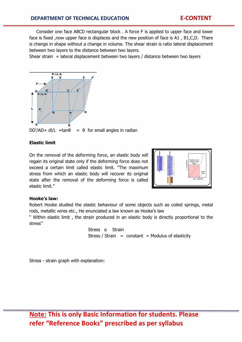
Consider one face ABCD rectangular block . A force F is applied to upper face and lower
face is fixed ,now upper face is displaces and the new position of face is A1 , B1,C,D. There
is change in shape without a change in volume. The shear strain is ratio lateral displacement
between two layers to the distance between two layers.
Shear strain = lateral displacement between two layers / distance between two layers
DD‟/AD= dl/L =tanθ = θ for small angles in radian
Elastic limit
On the removal of the deforming force, an elastic body will
regain its original state only if the deforming force does not
exceed a certain limit called elastic limit. ‟‟The maximum
stress from which an elastic body will recover its original
state after the removal of the deforming force is called
elastic limit.”
Hooke’s law:
Robert Hooke studied the elastic behaviour of some objects such as coiled springs, metal
rods, metallic wires etc., He enunciated a law known as Hooke‟s law
“ Within elastic limit , the strain produced in an elastic body is directly proportional to the
stress”
Stress α Strain
Stress / Strain = constant = Modulus of elasticity
Stress - strain graph with explanation:
Page 27
DEPARTMENT OF TECHNICAL EDUCATION E-CONTENT
Note: This is only Basic Information for students. Please refer “Reference Books” prescribed as per syllabus
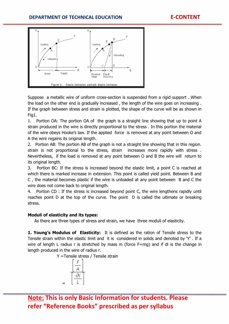
Suppose a metallic wire of uniform cross-section is suspended from a rigid support . When
the load on the other end is gradually increased , the length of the wire goes on increasing .
If the graph between stress and strain is plotted, the shape of the curve will be as shown in
Fig1.
1. Portion OA: The portion OA of the graph is a straight line showing that up to point A
strain produced in the wire is directly proportional to the stress . In this portion the material
of the wire obeys Hooke‟s law. If the applied force is removed at any point between O and
A the wire regains its original length.
2. Portion AB: The portion AB of the graph is not a straight line showing that in this region.
strain is not proportional to the stress, strain increases more rapidly with stress .
Nevertheless, if the load is removed at any point between O and B the wire will return to
its original length.
3. Portion BC: If the stress is increased beyond the elastic limit, a point C is reached at
which there is marked increase in extension. This point is called yield point. Between B and
C , the material becomes plastic if the wire is unloaded at any point between B and C the
wire does not come back to original length.
4. Portion CD : If the stress is increased beyond point C, the wire lengthens rapidly until
reaches point D at the top of the curve. The point D is called the ultimate or breaking
stress.
Moduli of elasticity and its types:
As there are three types of stress and strain, we have three moduli of elasticity.
1. Young’s Modulus of Elasticity: It is defined as the ration of Tensile stress to the
Tensile strain within the elastic limit and it is considered in solids and denoted by „Y‟ . If a
wire of length L radius r is stretched by mass m (force F=mg) and if dl is the change in
length produced in the wire of radius r.
Y =Tensile stress / Tensile strain
=
Page 28
DEPARTMENT OF TECHNICAL EDUCATION E-CONTENT
Note: This is only Basic Information for students. Please refer “Reference Books” prescribed as per syllabus
Y =
Where A = πr2 sq meter is area of cross section and F= mg in newton a stretching
force .
2. Bulk Modulus of Elasticity (K): It is defined as the ratio of Volume stress to the
Volume strain within elastic limit.
Bulk modulus =
Bulk modulus =
3. Modulus of Rigidity ( Shear modulus) ( ): It is defined as the ratio of Shear
stress to Shear strain within elastic limit.
Rigidity modulus =
Rigidity modulus =
Definition of Compressibility and factor of safety:
Compressibility:
It is the property by virtue of which a body can be
compressed so as to occupy smallest volume by the application of
external force. “ It is defined as reciprocal of bulk modulus of
elasticity (K)”.
Note: Gases are highly compressible, Liquids are slightly
compressible. The compressibility of solids varies from one material to another.
The S I unit of compressibility is square meter per newton.
Factor of safety:
Stress in a material should not exceed the elastic limit, if exceeds there would be a
permanent change in its physical dimension. Hence, factor of safety is used in common
practice.
Page 29
DEPARTMENT OF TECHNICAL EDUCATION E-CONTENT
Note: This is only Basic Information for students. Please refer “Reference Books” prescribed as per syllabus
It is defined as the ratio of ultimate stress to the working stress. Its value is
decided by the experience with the material used and also the type of use. It may vary
usually between 5 and 10.
Simple problems on stress, strain and Young’s modulus:
1. A steel of rectangular cross section 0.05m x 0.025m supports a load of 2 tonnes.
Calculate the stress.
Solution: stress = F/A = N/m2
2) A metal wire is 2.5mm in diameter and 2m long. A force of 12N is applied on it and it
stretches 0.3mm. Assume the material is elastic determine
i) Stress in wire
ii) Strain in the wire
Solution: Area of cross-section
A=
i) Stress = F/A =
ii) Strain =
3) A steel bar of length 6m and rectangular cross section 5cm x 2.5cm supports a load of
2tonnes. How much is change in length of the bar given Young‟s modulus for steel is 20 x
1010Nm-2 and g = 9.8ms-2
Solution:
L = 6m,
A=5cm x 2.5cm = 12.5 x 10⁻⁴m2,
F = 2000 x 9.8 = 19600N,
Y = 20 x 1010Nm-2
= 0.47 m
Properties of liquids
Thrust:
Liquid at rest always exerts a force perpendicular to the surface of contact. The surface may
be the bottom or walls of the containing vessels or a body immersed in the liquid. “The total
Page 30
DEPARTMENT OF TECHNICAL EDUCATION E-CONTENT
Note: This is only Basic Information for students. Please refer “Reference Books” prescribed as per syllabus
perpendicular force exerted by a liquid at rest on a surface in contact with it is called
thrust”.
Since thrust is force its SI unit is newton.
Pressure:
“ The normal force (thrust) exerted by liquid at rest on a unit area of the surface in contact
with it is called pressure of the liquid on the surface”.
If F is the normal force exerted by a liquid on a surface of area A, then pressure of the
liquid on the surface is,
Pressure P =
The S I unit of pressure is . When we describe pressure sometimes give special
name as Pascal (Pa) .
Derivation of expression for pressure at a point inside the liquid at rest:
Consider a cylinder of cross-sectional area A filled with a liquid of uniform density to a
height h as shown in fig( i ) . A normal force acts on the bottom of the cylinder due to the
weight of the liquid column inside. Therefore, pressure P exerted by the liquid column on
the bottom of the cylinder is,
P =
If m is the mass of the liquid in the cylinder , then F = mg
P= (m = Volume x density)
P=
Page 31
DEPARTMENT OF TECHNICAL EDUCATION E-CONTENT
Note: This is only Basic Information for students. Please refer “Reference Books” prescribed as per syllabus
Note:
1. the pressure exerted by a liquid at rest is independent of the size and shape of the
container P =
2. All the points at the same depth have the same pressure( g h ). As depth increases
pressure increases.
Simple problems:
1. Find the pressure at a point 10cm below the surface of liquid of density 0.8gm/cc
Solution:
h=10cm = 0.1m
=0.8gm/cc = 800
P = gh
P = 0.1 x 9.8 x 800
P = 7840
Energy of liquid in motion:
A moving liquid can possess the following types of energies
(i) Kinetic energy due to its motion.
(ii) Potential energy due to its position
(iii) Pressure energy due to the pressure of the liquid.
Kinetic, Potential energies and Pressure energy in moving liquid :
1. When the liquid is under motion the energy possess is called kinetic energy.
2. When the liquid is under motion the energy possess due to its position is called potential
energy.
3. When the liquid is under motion the energy possess due to its pressure is called pressure
energy.
Bernoulli’s theorem: statement and expression (No derivation):
Bernoulli‟s theorem is simply a statement of law of conservation of energy applied to
a liquid in motion. “ This theorem states that for the steady flow of an ideal liquid the total
energy ( ie sum of pressure energy , potential energy and kinetic energy) per unit volume
remains constant throughout the flow”.
where p = pressure energy per unit volume
gh = potential energy per unit volume
= kinetic energy per unit volume.
Page 32
DEPARTMENT OF TECHNICAL EDUCATION E-CONTENT
Note: This is only Basic Information for students. Please refer “Reference Books” prescribed as per syllabus
Cohesive and adhesive forces, angle of contact:
According to the molecular theory , matter is made up of minute particles called
molecules which attract each other. The intermolecular forces may be classified as:-
(i) Cohesive force
(ii) Adhesive force
(i)Cohesive force: “The force of attraction between the molecules of the same substance
is called force of cohesion or Cohesive force”. The force is cohesion is maximum in solids,
lesser in liquids and least in gases.
(ii)Adhesive force: “ The force of attraction between the molecules of the different
substances is called the force of adhesion or Adhesive force”. The force of adhesion is
different for different substances.
Note: some practical example of cohesive and adhesive forces:
1. The ink sticks on paper. It is because the adhesive force between ink and paper is
greater than the cohesive force of ink molecules.
2. Water wets glass. Because the adhesive force between water molecules and glass
molecules is greater than the force of cohesion between water molecules.
Page 33
DEPARTMENT OF TECHNICAL EDUCATION E-CONTENT
Note: This is only Basic Information for students. Please refer “Reference Books” prescribed as per syllabus
3. Mercury does not wet the glass because the adhesive force between mercury molecules
and glass molecules is less than the cohesive force between mercury molecules.
Angle of contact:
The angle of contact between a liquid and a solid is defined as the angle( ) which the
tangent to the liquid surface at the point of contact makes with the solid surface inside the
liquid.
Note:
1. When angle of contact is acute, adhesive force is greater than the cohesive force then,
i) The liquid will wet the solid.
ii) Meniscus of the liquid will be concave.
iii) Liquid will rise in the capillary tube.
2. when the angle of contact is obtuse, cohesive force is greater than the adhesive force
then
(i) Liquid will not wet the solid.
(ii) Meniscus of the liquid will be convex.
(iii) Liquid will get depressed in the capillary tube.
Surface Tension
The property of a liquid at rest by virtue of which its free surface behaves like a
stretched membrane under tension and tries to occupy as small area as possible is called
surface tension.
Observation:
(i) If a needle is slightly oiled so that the water cannot wet laid carefully on the surface of
water so that the film is not broken, it floats it can be observed that the surface is depressed
under the needle.
“Surface tension of a liquid can be measured as the force per unit length in the plane of
the liquid surface acting at right angles on either side of an imaginary line drawn on the
liquid surface ”.
Image:
Surface tension = =
The S I unit of surface tension is newton per metre.
Page 34
DEPARTMENT OF TECHNICAL EDUCATION E-CONTENT
Note: This is only Basic Information for students. Please refer “Reference Books” prescribed as per syllabus
Factors affecting surface tension:
The surface tension of a liquid depends upon
1. Nature of liquid: Different liquids have different surface tensions
2. Contamination : Impurities in a liquid lower its surface tension .
3. Temperature: The surface tension of a liquid decreases with the increase in temperature.
Applications of surface tension:
1. Liquid drops will be perfectly spherical in the absence of gravity, this effect can be
observed in the manufacture of lead shots. The freely falling metal temporarily looses its
weight and spherical drops are formed due to surface tension.
2. Wetting agent or detergent such as aerosol or petro wet lowers the surface tension of
water . Hence cloth becomes wet easily in such water.
3. Mosquitos hang their eggs from the surface of water .when a small amount of oil is
poured on water the surface tension of water is reduced ,this breaks the elastic film of water
surface and mosquitoes eggs are drowned.
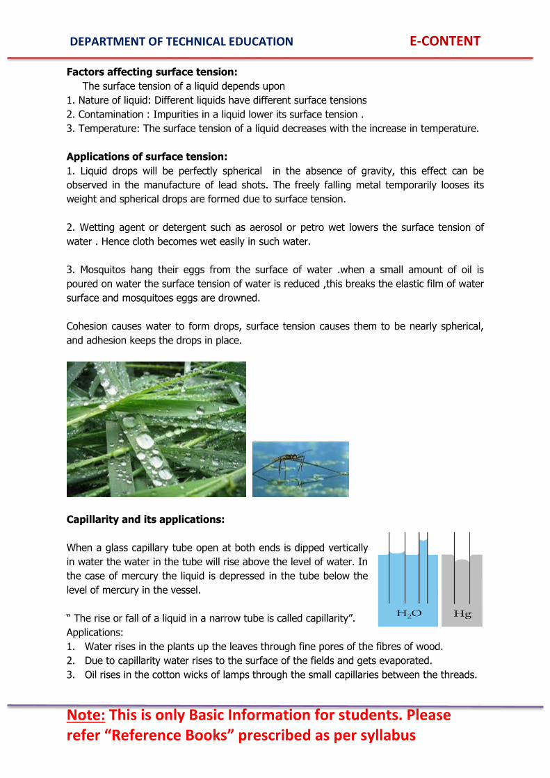
Cohesion causes water to form drops, surface tension causes them to be nearly spherical,
and adhesion keeps the drops in place.
Capillarity and its applications:
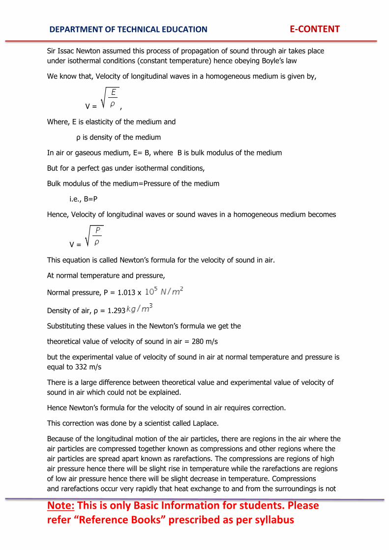
When a glass capillary tube open at both ends is dipped vertically
in water the water in the tube will rise above the level of water. In
the case of mercury the liquid is depressed in the tube below the
level of mercury in the vessel.
“ The rise or fall of a liquid in a narrow tube is called capillarity”.
Applications:
1. Water rises in the plants up the leaves through fine pores of the fibres of wood.
2. Due to capillarity water rises to the surface of the fields and gets evaporated.
3. Oil rises in the cotton wicks of lamps through the small capillaries between the threads.
Page 35
DEPARTMENT OF TECHNICAL EDUCATION E-CONTENT
Note: This is only Basic Information for students. Please refer “Reference Books” prescribed as per syllabus
4. Coffee powder is easily soluble in water because water immediately wets the fine
granules of coffee by capillary action.
Viscosity
Types of flow of liquid:
The liquid flow is of two main types
(i) Stream line flow or steady flow: The flow of a liquid is said tobe streamline flow if all the
liquid particles that pass any given point follow the same path at the same speed(same
velocity).
(ii)Turbulent flow : The flow of a liquid is said to be turbulent flow if the speed and
direction of the liquid particles passing any point change with time
Definition of viscosity :
“ The property of a moving fluid to oppose the relative motion
between its layers is called viscosity” .
(Note: the viscosity is that property of a fluid that indicates its
internal friction ,the greater the viscosity of a fluid the greater is
the force required to cause one layer of fluid to slide another.)
Expression for coefficient of viscosity:
When a fluid is set in motion, different layers of
the fluid move with different velocities. Consider a
Page 36
DEPARTMENT OF TECHNICAL EDUCATION E-CONTENT
Note: This is only Basic Information for students. Please refer “Reference Books” prescribed as per syllabus
liquid flowing slowly over a fixed horizontal surface , the layer of liquid in contact with
horizontal surface is at rest and velocity of layers increases with distance from the fixed
surface. Considering any particular layer of the liquid ,the layer below it moves slower than
it and one above it moves faster than it. Because of this lower layer tends to retard the
motion of upper layer which tends to accelerate it.
Newton showed that the viscous force acting tangentially on any liquid layer is:
1. Directly proportional to surface area A
2. Directly proportional to velocity V
3. Inversely proportional to its distance from stationary layer X
F α
F = if A = 1 sq cm, V= 1cm/s , X = 1cm
F = -
Therefore the coefficient of viscosity( ) of a liquid is the tangential force required per unit
area to maintain unit relative velocity between two layers unit distance apart.
Experimental determination of coefficient of viscosity of water:
Aim: To determine the coefficient of viscosity of water by poissolue‟s method.
Apparatus: aspirator bottle, beaker, capillary tube, stop watch water etc.,
Principle: According to poiseuille‟s equation , the volume of liquid flowing per second
through a narrow tube of radius r and length L is given by : V= ????????? Where P is the
pressure difference between the two ends of the tube, where ( ) is co-efficient of viscosity
of liquid flowing through the narrow tube.
Procedure: The experiment consists of two parts:
(i) The radius of capillary tube is first using travelling microscope, initially L.C of Travelling
Microscope is obtained by knowing value of one main scale division and number of divisions
Page 37
DEPARTMENT OF TECHNICAL EDUCATION E-CONTENT
Note: This is only Basic Information for students. Please refer “Reference Books” prescribed as per syllabus
on vernier. Capillary tube is fixed horizontally to the stand. The bore of capillary is focused
and crosswire of T.M is set tangential on one side and reading R1is taken , then cross wire
is shifted to diametrically opposite tangential position and reading R2 taken. The difference
between these two readings gives diameter. Hence radius is obtained.
Observation:
Least count of T.M = cm
Tabular column:
Trial no. T.M reading for Capillary tube Diameter
d= R1- R2 Radius=d/2
Left R1 Right R2
(ii) Volume of water coming out per second from capillary is determined as below, fix the
capillary tube horizontally at the bottom of reservoir, maintained with constant height h of
liquid above the axis of the capillary tube. Collect the water coming out per second ,measure
length L of the capillary tube, thus knowing r and v , co-efficient of viscosity ( ) can be
calculated.
Observation:
Acceleration due to gravity (g):
Density of water :
Length of capillary tube L :
Pressure P : g h
Tabular column:
Trial No.
Pressure head
h=
cm
Volume
V
cc
T sec
Mean
Initial
height
h1
Final
Height
h2
Co-efficient of Viscosity = poise
Effect of temperature on viscosity:
(i) The viscosity of ideal liquid is zero.
(ii) The coefficient of viscosity of a liquid decreases with the increase in temperature and
vice-versa.
(iii)The coefficient of viscosity of gases increases with the increase in temperature.
Page 38
DEPARTMENT OF TECHNICAL EDUCATION E-CONTENT
Note: This is only Basic Information for students. Please refer “Reference Books” prescribed as per syllabus
List of applications of viscosity:
1. Blood circulation through arteries depends upon the viscosity of blood.
2. The shapes of ships, cars, aeroplanes etc., are streamlined so as to overcome viscous
resistance of water or air.
3. Oil used as a lubricant should have proper value of viscosity.
4. Viscosity of air or liquid is used in providing damping torque in measuring instruments.
Simple problems:
1) A plate of metal 200sqcm. In area rests on layer of castor oil 2mm, thick whose
coefficient of viscosity is 15.5 poise. Calculate the horizontal force required to move the
plate with a speed of 3cm/sec.
Solution: Horizontal force required F = ?
F= -
= - 15.5 X 200 X (3/0.2) = 46500 dynes
UNIT III: HEAT AND PROPERTIES OF GASES.
What is Heat?
All matter is made up of molecules and atoms. These atoms are always in different
types of motion (translation, rotational, vibrational). The motion of atoms and molecules
Page 39
DEPARTMENT OF TECHNICAL EDUCATION E-CONTENT
Note: This is only Basic Information for students. Please refer “Reference Books” prescribed as per syllabus
creates heat or thermal energy. All matter has this thermal energy. If the motion the atoms
or molecules is more then, they have more heat or thermal energy.
In day-to-day conversation talking about heat as if it's contained in something. This
distinction between heat and temperature is subtle, but very important.
For Example: The iron is hot, so it's reasonable to say it must have a lot of heat in it.
Reasonable, but wrong. It's more appropriate to say that it has a lot of energy in it (i.e. it
has a high temperature), and touching it will cause that energy to transfer to your hand ...
in the form of heat.
Heat is the total energy of molecular motion in a substance while temperature is a
measure of the average energy of molecular motion in a substance. Heat energy depends
on the speed of the particles, the number of particles (the size or mass) and the type of
particles in an object.
If the heat energy is used to change the state of the substance, say by melting it,
then the added energy is used to break the bonds between the molecules rather than
changing their kinetic energy.
In physical equations, the amount of heat transferred is usually denoted with the symbol Q.
SI UNIT:
As a form of energy, the SI unit for heat is the joule (J).
Heat is frequently measured in calorie, which is defined as "the amount of heat required to
raise the temperature of one gram of water from 14.5 degrees Celsius to 15.5 degrees
Celsius."
Temperature is not energy, but a measure of heat energy. Temperature is a number
that is related to the average kinetic energy of the molecules of a substance. It does not say
that temperature is kinetic energy, nor does it state exactly what is the relation between
temperature and kinetic energy.
Here is the relation: If temperature is measured in Kelvin degrees, then the value of
temperature is directly proportional to the average kinetic energy of its molecules that
means if you double the Kelvin temperature of a substance, you double the average kinetic
energy of its molecules of a substance.
Temperature can be measured in a variety of units. Namely Kelvin, Centigrade and
Fahrenheit. The SI unit of temperature is Kelvin.
Temperature does not depend on the size or type of object. For example, the
temperature of a small cup of water might be the same as the temperature of a large tub of
water, but the tub of water has more heat because it has more water and thus more total
thermal energy.
Page 40
DEPARTMENT OF TECHNICAL EDUCATION E-CONTENT
Note: This is only Basic Information for students. Please refer “Reference Books” prescribed as per syllabus
It is heat that will increase or decrease the temperature. If we add heat, the
temperature will become higher. If we remove heat the temperature will become lower.
Higher temperatures mean that the molecules are moving, vibrating and rotating with more
energy.
If we take two objects which have the same temperature and bring them into
contact, there will be no overall transfer of energy between them because the average
energies of the particles in each object are the same. But if the temperature of one object is
higher than that of the other object, there will be a transfer of energy from the hotter to the
colder object until both objects reach the same temperature.
When heat energy goes into a substance one of two things can happen:
1. The substance can experience a rise in temperature.
2. The substance can change state (or phase). For example, if the substance is ice, it can
melt into water. Perhaps surprisingly, this change does not cause a rise in temperature. At
the exact moment before melting, the average kinetic energy of the ice molecules is the
same as the average kinetic energy of the water molecules at the exact moment after
melting. That is, the melting ice and the just melted water are at the same temperature.
Although heat (energy) is absorbed by this change of state, the absorbed energy is not used
to change the average kinetic energy of the molecules, and thus proportionally change the
temperature.
Specific heat
Specific Heat Capacity Definition: Specific heat capacity is the amount of heat energy
required to raise the temperature of unit of mass of a body by unit degree temperature.
In SI units, specific heat capacity (symbol: c) is the amount of heat in joules required to
raise temperature of 1 kg of a substance by 1 kelvin.
Also Known As: specific heat, mass specific heat.
Examples: Water has a specific heat capacity of 4.18 J.
Copper has a specific heat capacity of 0.39 J.
Equation for specific heat of a substance ( no derivation).
If Q amount of heat is required to raise the temperature of a body of mass m from
temperature t1 to temperature t2 , so that the raise in temperature is t2 – t1 =t
then we have, amount of heat
Q is directly proportional to m (mass)
Q is directly proportional to t (raise in temperature)
ie., Q is directly proportional to mt.
To remove proportionality we introduce proportionality constant, c called Specific heat
Hence, Q mt
Q = cmt
Page 41
DEPARTMENT OF TECHNICAL EDUCATION E-CONTENT
Note: This is only Basic Information for students. Please refer “Reference Books” prescribed as per syllabus
c =
SI unit of Specific heat is J per kg-s
Transmission of heat
Conduction
Transfer of heat from one place to another
without the actual movement of heated medium
particles is called conduction of heat.
Conduction is probably the most basic and
intuitive way of achieving heat transfer.
Conduction is the transfer of heat between
substances that are in direct contact with each
other. The better the conductor, the more rapidly
heat will be transferred. Metal is a good conductor
of heat.
When a hot body touches some cool body, the cool body heats up.
Conduction occurs when a substance is heated. Particles will gain more energy, and vibrate
more. These molecules then bump into nearby particles and transfer some of their energy to
them. This then continues and passes the energy from the hot end down to the colder end
of the substance.
For instance, if you drop an egg into that boiling water, the heat from the water is
then transferred to the egg. As the outer parts of the egg heat up, that heat is transferred
inward, so that it is the hotter parts of the egg that end up cooking the cooler, interior parts
of itself. So the transfer of heat from one part of an object to another part of the same
object is also considered conduction.
How efficiently heat is transferred in this way depends on the conductivity of the
items involved. Copper is an extremely good conductor of heat, which means heat moves
through copper cookware and is transferred to the food very quickly.
Applications of conduction
Hot soup burning your tongue
Burning your hand on holding hot objects
Age of Earth
Convection
Transfer of heat from one place to another
with the movement of heated medium particles is
called convection of heat.
Whereas conduction is a static process,
convection is a more efficient method of heat
transfer because it adds the element of motion.
Page 42
DEPARTMENT OF TECHNICAL EDUCATION E-CONTENT
Note: This is only Basic Information for students. Please refer “Reference Books” prescribed as per syllabus
Convection occurs when warmer areas of a liquid or gas rise to cooler areas in the liquid or
gas because of decrease in density. Cooler liquid or gas then takes the place of the warmer
areas which have risen higher. This results in a continuous circulation pattern.
Water boiling in a pan is a good example of these convection currents.
Stirring a pot of soup would be considered a form of convection, as it redistributes the heat
from the bottom of a pot throughout the soup.
A convection oven heats food faster than an ordinary one because it has a fan that
blows the hot air around, convection ovens can reduce cooking time by 25% or more
compared with ordinary ovens.
Another good example of convection is in the atmosphere. The earth's surface is
warmed by the sun, the warm air rises and cool air moves in.
Applications of convection
Land and sea breeze
Boiling water
Cooling system in automobiles.
Radiation
Transfer of heat from one place to
another without the help of the medium.
Radiation is a method of heat transfer that
does not depend upon any contact between
the heat source and the heated object as in
the case of conduction and convection. Heat
can be transmitted though empty space by
thermal radiation often called infrared
radiation. This is a type electromagnetic
radiation. No mass is exchanged and no medium is required in
the process of radiation.
Examples of radiation are the heat from the sun reaching earth,
Heat released from the filament of a light bulb.
Page 43
DEPARTMENT OF TECHNICAL EDUCATION E-CONTENT
Note: This is only Basic Information for students. Please refer “Reference Books” prescribed as per syllabus
Applications of radiation
1. Buildings which are white-washed or painted in light colours keep cooler in summer, since
the light surfaces reflect radiant heat from the sun.
2. Many factory roofs are aluminium-painted. The bright surface reduces the heat lost in
winter, and keeps the interior cool in summer.
3. We choose light-colored clothing in summer for the same reason, and in very hot
countries white clothing is generally the rule.
4. Brightly polished objects retain their heat for a long period. This is one reason why silver
teapot is to be preferred to others.
Thermal conductivity
Definition: The rate at which heat is transferred by conduction through a unit cross-
sectional area of material when a temperature gradient exists perpendicular to the area.
The coefficient of thermal conductivity, called the k-factor, is expressed as the quantity of
heat that passes through a unit cube of the substance in unit time when the difference in
temperature of the two faces is 1 °.
Derivation of co-efficient of thermal conductivity (k) and its S.I unit.
Consider a metallic rod of length 'l', cross
sectional area A which is heated at one end. Heat
flows to the other end by the method of
conduction. If the temperature of first end is
maintained at and the temperature at the other
end is maintained at so that . The amount of
heat Q conducted through the metallic rod for the
time 'T'seconds is
1. Directly proportional to area A
2. Directly proportional to temperature difference
3. Directly proportional to the time for which heat is conducted T
4. Inversely proportional to the length of the rod 'l'
Therefore Q
Q = k.
Page 44
DEPARTMENT OF TECHNICAL EDUCATION E-CONTENT
Note: This is only Basic Information for students. Please refer “Reference Books” prescribed as per syllabus
Where k is proportionality constant.
Thus the coefficient of thermal conductivity is defined as the quantity of heat (Q)
transmitted through a unit thickness (l) in a direction normal to a surface of unit area (A)
due to a unit temperature difference(ΔT) for unit time T under steady state conditions.
In equation form this becomes the following:
Thermal Conductivity k = Quantity of heat Q
In SI thermal conductivity is measured in joules per meter kelvin second or J/mKs.
Simple problem on thermal conductivity, k.
How much heat will be lost per square metre per hour from the body of a person,
whose body temperature is 37 C, wearing 1mm thick tight cloth when the atmospheric
temperature is 26 C ?
Given coefficient of thermal conductivity of the material of cloth is
0.04joule/second.metre.kelvin.
Given Data:
k = 0.04joule/second.metre.kelvin.
A = 1 sq.metre
t1 = 37 + 273 = 310 K
t2 = 26 + 273 = 299 K
t1 – t2 = 310 - 299 = 11 K
T = 1hour = 3600 seconds
l = 1mm = 0.001m
We know that, amount of heat conducted
Q = k. (A(t1-t2)T/l joules
Substituting,
Q = (0.04x1x11x3600)/0.001
Q = 1584000 joules
Gas laws
The gas laws were developed at the end of the 18th century, when scientists began
to realize that relationships between pressure, volume and temperature of a sample of gas
could be obtained which is approximately same for all gases. Gases behave in a similar way
over a wide variety of conditions because they all have molecules which are widely spaced.
The earlier gas laws are now considered as special cases of the ideal gas equation, with one
or more of the variables held constant.
Boyle's Law, published in 1662. It states that, for a given mass of an ideal gas, in a closed
system, at constant temperature, the product of the pressure and volume is always
constant.
It can be verified experimentally using a pressure gauge and a variable volume container. It
can also be derived from the kinetic theory of gases: if a container, with a fixed number of
molecules inside, is reduced in volume, more molecules will strike a given area of the sides
of the container per unit time, causing a greater pressure.
As a mathematical equation, Boyle's Law is written as either:
Page 45
DEPARTMENT OF TECHNICAL EDUCATION E-CONTENT
Note: This is only Basic Information for students. Please refer “Reference Books” prescribed as per syllabus
, or
, or
where P is the pressure, and V is the volume of a gas.
Charles’ Law: or the law of volumes, was found in 1787 by Jacques Charles. It states that,
for a given mass of an ideal gas at constant pressure, the volume is directly proportional to
its absolute temperature assuming a closed system.
As a mathematical equation, Charles‟ Law is written as either:
, or
, or
where V is the volume of a gas, T is the absolute temperature.
Gay-Lussac's Law, or the Pressure Law, was found by Joseph Louis Gay-Lussac in
1809. It states that, for a given mass of an ideal gas and at constant volume, the pressure
exerted on the sides of its container is directly proportional to its absolute temperature.
As a mathematical equation, Gay-Lussac's Law is written as either:
, or
, or
where P is the pressure, T is the absolute temperature.
Derivation of the relation between them (PV= nRT)
Page 46
DEPARTMENT OF TECHNICAL EDUCATION E-CONTENT
Note: This is only Basic Information for students. Please refer “Reference Books” prescribed as per syllabus
Derivation of perfect gas equation
Step 1: Write Boyle's Law:
P1V1 = P2V2
Step 2: Multiply by Charles Law:
P1(V1)2 / T1 = P2(V2)
2 / T2
Step 3: Multiply by Gay-Lussac's Law:
(P1)2(V1)
2 / (T1)2 = (P2)
2(V2)2 / (T2)
2
Step 4: Take the square root to get the combined gas law:
P1V1 / T1 = P2V2 / T2
or, = constant = R
Therefore, PV = RT
For n moles of gas, PV = nRT
Specific Heat Capacity in case of gases:
For solids and liquids we define the specific heat capacity as the quantity of energy that will
raise the temperature of unit mass of the body by 1 K. For gases, however, it is necessary
to specify the conditions under what condition the change of temperature takes place, since
a change of temperature will also produce large changes in pressure and volume.
For solids and liquids we can neglect this pressure change and the specific heat
capacity that we measure for them is essentially one where the pressure on the body is
unaltered. We call this the specific heat capacity at constant pressure (CP).
The specific heat capacity at constant volume (CV) is defined as the quantity of heat
required to raise the temperature of 1 kg of the gas by 1 K if the volume of the gas
remains constant.
The specific heat capacity at constant pressure (CP) is defined as the quantity of heat
required to raise the temperature of 1 kg of the gas by 1 K if the pressure of the gas
remains constant.
The specific heat capacity at constant pressure (CP) is always greater than that at
constant volume (CV). Since if the volume of the gas increases work must be done by the
gas to push back the surroundings.
Relation between CP and CV
Page 47
DEPARTMENT OF TECHNICAL EDUCATION E-CONTENT
Note: This is only Basic Information for students. Please refer “Reference Books” prescribed as per syllabus
1. CP - CV =R, where R is Universal gas constant.
This equation is called Mayer‟s equation.
2.
The value of this ratio depends on the atomicity of the gas – in other words how many
atoms there are in one molecule.
Problems on Gas laws
Boyle’s law
A container holds 500ml of Carbon-di-oxide at C and 742 mm of mercury. What will be the
volume of Carbon-di-oxide if the pressure is increased to 795 mm of mercury?
Given Data:
V1 = 500 ml
P1 = 742 mm of Hg.
P2 = 795 mm of Hg.
T = 20C
WE know that,
P1.V1 = P2.V2
V2 = ?
V2 = (P1.V1)/P2
V2 = (742 x 500) / 795
V2 = 466.66 ml of Carbon-di-oxide
Charles’ law
A container holds 100ml of nitrogen at C and a pressure of 736 mm of mercury. What will
be its volume if the temperature is increased by C
Given Data:
V1 = 100 ml
T1 = 25 + 273 = 298 K
P1 = 736 mm of Hg.
T2 = (25 + 35) + 273 = 333 K
V2 = ?
WE know that,
V1/T1 = V2 / T2
V2 = (V1.T2)/T1
V2 = (100 x 333) / 298
V2 = 111.744967 ml of nitrogen
Thermodynamics:
It is a branch of physics concerned with heat and temperature and their relation to
energy and work. It defines macroscopic variables, such as internal energy, entropy, and
pressure that partly describe a body of matter or radiation.
Page 48
DEPARTMENT OF TECHNICAL EDUCATION E-CONTENT
Note: This is only Basic Information for students. Please refer “Reference Books” prescribed as per syllabus
The field of thermodynamics deals with systems that are able to transfer thermal
energy into at least one other form of energy (mechanical, electrical, etc.) or into work. The
laws of thermodynamics were developed over the years as some of the most fundamental
rules which are followed when a thermodynamic system goes through some way of energy
change.
Zeroeth law of thermodynamics:
If two systems are in thermal equilibrium respectively with a third system, then they
must be in thermal equilibrium with respect to each other.
This zeroeth law is sort of a transitive property of thermal equilibrium. The transitive
property of mathematics says that if A = B and B = C, then A = C. The same is true of
thermodynamic systems that are in thermal equilibrium.
In order to measure a temperature, thermal equilibrium much be reached between
the thermometer as a whole, the mercury inside the thermometer, and the substance being
measured. This, in turn, results in being able to accurately tell what the temperature of the
substance is.
This law was understood without being explicitly stated through much of the history
of thermodynamics study. British physicist Ralph H. Fowler first coined the term "zeroeth
law," based on a belief that it was more fundamental even than the other laws.
First law of thermodynamics:
When energy passes,( as work, as heat or with matter,) into a system or out from a
system, its internal energy changes in accordance with the law of conservation of energy.
The change in a system's internal energy is equal to the difference between heat added to
the system from its surroundings and work done by the system on its surroundings.
The first law of thermodynamics is seen by many as the foundation of the concept of
conservation of energy. It basically says that the energy that goes into a system is
usedeither to change internal energy or to perform work or both.
Second law of thermodynamics:
In a natural thermodynamic process, the sum of the entropies of the interacting
thermodynamic system increases. It is impossible for a process to transfer heat from a
cooler body to a hotter one.
Page 49
DEPARTMENT OF TECHNICAL EDUCATION E-CONTENT
Note: This is only Basic Information for students. Please refer “Reference Books” prescribed as per syllabus
Each time a system goes through a thermodynamic process, the system can never
completely return to the same state it was in before. This is one definition used for the
arrow of time, since entropy of the universe will always increase over time according to the
second law of thermodynamics.
Types of thermodynamics process
Isothermal Process
An isothermal process is a thermodynamic process in which the temperature of the
system remains constant, the heat transfer into the system or out of the system must
happen at such a slow rate that the thermal equilibrium is maintained.
Other Factors in an Isothermal Process
An isothermal process is a change of a system, in which the temperature remains constant:
ΔT = 0.
In general, during an isothermal process there is a change in internal energy, heat energy
and work.
The internal energy of an ideal gas, however, depends solely on the temperature, so the
change in internal energy during an isothermal process for an ideal gas is also 0.
Adiabatic Process
An adiabatic process is one that
occurs without transfer of heat or matter
between a system and its surroundings.
Here no heat is gained or lost by the
system.
An adiabatic process is generally
obtained by surrounding the entire system
with a strongly insulating material or by
carrying out the process so quickly that
there is no time for a significant heat transfer to take place.
Other Factors in an Adiabatic Process
A system that expands under adiabatic conditions does positive work, so the internal
energy decreases.
A system that contracts under adiabatic conditions does negative work, so the
internal energy increases.
Page 50
DEPARTMENT OF TECHNICAL EDUCATION E-CONTENT
Note: This is only Basic Information for students. Please refer “Reference Books” prescribed as per syllabus
Eg. The compression and expansion strokes in an internal-combustion engine are both
approximately adiabatic processes
UNIT IV: WAVE MOTION
Introduction and simple harmonic motion Periodic motion: A motion that repeats itself in equal intervals of time is called Periodic
motion.
Example: A rocking chair, a bouncing ball, a vibrating tuning fork, a swing in motion,
the Earth in its orbit around the Sun, and a water wave.
Page 51
DEPARTMENT OF TECHNICAL EDUCATION E-CONTENT
Note: This is only Basic Information for students. Please refer “Reference Books” prescribed as per syllabus
Simple harmonic motion
Simple harmonic motion is a type of periodic motion where the restoring force is
directly proportional to the displacement and acts in the direction opposite to that of
displacement.
Example: A rocking chair, a vibrating tuning fork, a swing in motion, pendulums, springs
Derivation of displacement of a particle executing Simple Harmonic Motion.
Definitions of period, frequency, amplitude, in case of vibrating particle. Definition of wave,
wave period (T), wave frequency (n or f), wave amplitude (a), wave length (λ) and wave
velocity (v) in case of wave motion.
Derive the relation between v, n and λ. .
Vibratory motion can be defined as to and fro motion or oscillatory motion about a mean
position.
Definitions of period, frequency, amplitude, in case of vibrating particle
Page 52
DEPARTMENT OF TECHNICAL EDUCATION E-CONTENT
Note: This is only Basic Information for students. Please refer “Reference Books” prescribed as per syllabus
Period: Time required to complete one cycle or one to and fro motion is called period.
Denoted by „T‟ and its SI unit is second.
Frequency: Total number of cycles completed by the body in one second. Denoted by „n‟ or
„f‟ and its SI unit is hertz.
Amplitude: Maximum displacement of the particle from the mean position is amplitude.
Denoted by „a‟ and its SI unit is meter.
Wave: A wave is a vibratory disturbance in a medium which carries energy from one point
to another without any direct contact between the two points.
In other words a wave is an oscillation accompanied by the transfer of energy that
travels through space or mass. Wave motion transfers energy from one point to another,
which may or may not displace particles of the medium with little or no associated mass
transport. Waves consist of oscillation or vibrations (of a physical quantity), around fixed
locations.
Wave period (T): The period of a wave is the time required for a particle on a medium to
make one complete vibrational cycle. Period, being a time, is measured in units of time such
as seconds, hours, days or years. Its SI unit is seconds.
Wave frequency (n or f): The frequency of a wave refers to how many times the particles
of the medium vibrate in unit time when a wave passes through the medium. Its SI unit is
hertz.
Wave amplitude (a): The amplitude of a wave refers to the maximum amount of
displacement of a particle on the medium from its rest position. Its SI unit is metre.
For example in transverse wave , the amplitude is the distance from rest to crest.
Similarly, the amplitude can be measured from the rest position to the trough position.
Page 53
DEPARTMENT OF TECHNICAL EDUCATION E-CONTENT
Note: This is only Basic Information for students. Please refer “Reference Books” prescribed as per syllabus
Wave length (λ):The wave length of a wave is simply the length of one complete wave
cycle. Its SI unit is metre.
Wave velocity (v): The distance travelled by the wave or disturbance in unit time is called
wave velocity. Its SI unit is metre/second.
Derive the relation between v, n and λ.
Consider a wave of wave length „λ‟, wave period „T‟ and frequency „n‟ travelling in a medium
with wave velocity „v‟. During one oscillation of the medium particle the distance travelled by
the wave is one wave length λ and time taken for this is one wave period T.
We know that wave velocity is distance travelled by the wave/time taken Therefore, wave
velocity v= wave length λ/ wave period T
But wave period T = =
Substituting we get v = n λ
Simple problems.
1. Sound wave travelling in air with frequency 12 kHz has a velocity of 332 m/s. Find the
wavelength of this wave in air.
Solution:
Page 54
DEPARTMENT OF TECHNICAL EDUCATION E-CONTENT
Note: This is only Basic Information for students. Please refer “Reference Books” prescribed as per syllabus
2. A radio station broadcasts programs on a wavelength of 300 m. Find the frequency of
broadcasting.
Solution:
Data:
Velocity of radio wave = Velocity of Electromagnetic wave =
Mechanical Waves and NonMechanical Waves or Electromagnetic waves.
Mechanical Waves are waves which
propagate through a material medium (solid,
liquid, or gas) at a wave speed which
depends on the elastic and inertial properties
of that medium. Mechanical waves propagate
through a medium, and the substance of this
medium is deformed. The deformation
reverses itself owing to restoring forces
resulting from its deformation. For example,
sound waves propagate via air molecules
colliding with their neighbours. When air
molecules collide, they also bounce away
from each other (a restoring force). This keeps the molecules from continuing to travel in
the direction of the wave.
Examples for this type of waves are water waves, sound waves.
Page 55
DEPARTMENT OF TECHNICAL EDUCATION E-CONTENT
Note: This is only Basic Information for students. Please refer “Reference Books” prescribed as per syllabus
Let an electric bell be
enclosed within a bell jar which is
placed over a disc. we hear
sound, transmitted through the
air when it is rung. On gradually
removing the air, the sound of
the bell becomes feebler and
becomes almost inaudible when
the limit of exhaustion is reached.
In air, sound is propagated in the
form of compressions and
rarefactions i.e., longitudinal
waves. Unlike light, sound
cannot pass through vacuum.
The second main type of wave is Non Mechanical Waves or Electromagnetic waves, which
do not require a medium. Instead, they consist of periodic oscillations of electrical and
magnetic fields generated by charged particles, and can therefore travel through vacuum.
Examples for this type of waves are radio waves, microwaves infrared waves, visible light
etc.
There are two types of mechanical waves:
Longitudinal waves and transverse waves
Longitudinal wave:
A wave in which the particles of the
medium vibrate back and forth(oscillate) in the
same direction in which the wave is moving, is
called a longitudinal wave. Longitudinal wave can
be produced in all the three medium solids,
liquids, and gases.
Transverse wave:
Page 56
DEPARTMENT OF TECHNICAL EDUCATION E-CONTENT
Note: This is only Basic Information for students. Please refer “Reference Books” prescribed as per syllabus
A wave in which the particles of the
medium vibrate back and
forth(oscillate) in the direction
perpendicular to the direction in
which the wave is moving, is called
a transverse wave. Transverse
wave can be produced in medium
solids, and liquid surfaces.
Differences between longitudinal waves and transverse waves
Longitudinal waves Transverse waves
1. The particle displacement is parallel to the
direction of wave propagation.
1. The particle displacement is perpendicular
to the direction of wave propagation.
2.Sound waves in air is an example 2.Ripples on water surface is an example
3.Compression and rarefaction are formed 3.Crest and trough are formed
4. Longitudinal waves cannot be polarised 4. Transverse waves can be polarised
5. Pressure and density changes as
the longitudinal wave propagates
5. Pressure and density remains same as the
transverse wave propagates
6. Longitudinal waves can propagate through
solids, liquids and gases
6. Transverse waves can propagate through
solids and liquid surfaces.
Sound: A form of energy produced by vibrating objects. When sound travels through a
material such as air, molecules in the material vibrate and bump into the molecules, passing
on their energy.
Wave: A wave is a vibratory disturbance in a medium which carries energy from one point
to another without any direct contact between the two points.
Page 57
DEPARTMENT OF TECHNICAL EDUCATION E-CONTENT
Note: This is only Basic Information for students. Please refer “Reference Books” prescribed as per syllabus
Longitudinal wave: A wave in which the particles of the medium vibrate back and forth in
the same direction, in which the wave is moving is called a longitudinal wave. Longitudinal
wave can be produced in all the three medium solids, liquids and gases.
Sound waves are longitudinal waves:
When a sound wave passes through
air, the particles of air vibrate back and forth
parallel to the direction of sound wave. Thus,
when a sound wave travels in the horizontal
direction, then the particles of the medium also
vibrate back and forth in the horizontal
direction but parallel to the direction of sound
Newton’s formula for the velocity of sound in air and Laplace’s correction to it,
various factors affecting velocity of sound in air
Sound is a mechanical wave that results from the back and forth vibration of the particles of
the medium through which the sound wave is moving. If a sound wave is moving from left
to right through air, then particles of air will be displaced both rightward and leftward as the
energy of the sound wave passes through it. The motion of the particles is parallel to the
direction of the energy transport. This is what characterizes sound waves in air as
longitudinal wave.
A vibrating tuning fork is capable of creating such a longitudinal wave. As the prongs of the
fork vibrate back and forth, they push on neighbouring air particles. The forward motion of a
prong pushes air molecules horizontally to the right and the backward retraction of the
prong creates a low-pressure area allowing the air particles to move back to the left.
Because of the longitudinal motion of the air particles, there are regions in the air where the
air particles are compressed together and other regions where the air particles are spread
apart. These regions are known as compressions and rarefactions respectively. The
compressions are regions of high air pressure while the rarefactions are regions of low air
pressure.
Page 58
DEPARTMENT OF TECHNICAL EDUCATION E-CONTENT
Note: This is only Basic Information for students. Please refer “Reference Books” prescribed as per syllabus
Sir Issac Newton assumed this process of propagation of sound through air takes place
under isothermal conditions (constant temperature) hence obeying Boyle‟s law
We know that, Velocity of longitudinal waves in a homogeneous medium is given by,
V = ,
Where, E is elasticity of the medium and
ρ is density of the medium
In air or gaseous medium, E= B, where B is bulk modulus of the medium
But for a perfect gas under isothermal conditions,
Bulk modulus of the medium=Pressure of the medium
i.e., B=P
Hence, Velocity of longitudinal waves or sound waves in a homogeneous medium becomes
V =
This equation is called Newton‟s formula for the velocity of sound in air.
At normal temperature and pressure,
Normal pressure, P = 1.013 x
Density of air, ρ = 1.293
Substituting these values in the Newton‟s formula we get the
theoretical value of velocity of sound in air = 280 m/s
but the experimental value of velocity of sound in air at normal temperature and pressure is
equal to 332 m/s
There is a large difference between theoretical value and experimental value of velocity of
sound in air which could not be explained.
Hence Newton‟s formula for the velocity of sound in air requires correction.
This correction was done by a scientist called Laplace.
Because of the longitudinal motion of the air particles, there are regions in the air where the
air particles are compressed together known as compressions and other regions where the
air particles are spread apart known as rarefactions. The compressions are regions of high
air pressure hence there will be slight rise in temperature while the rarefactions are regions
of low air pressure hence there will be slight decrease in temperature. Compressions
and rarefactions occur very rapidly that heat exchange to and from the surroundings is not
Page 59
DEPARTMENT OF TECHNICAL EDUCATION E-CONTENT
Note: This is only Basic Information for students. Please refer “Reference Books” prescribed as per syllabus
possible .(do not take place.) So this process of propagation of sound through air takes
place under adiabatic conditions and not under isothermal conditions.
For a perfect gas under adiabatic conditions,
Bulk modulus of the medium is of the medium
where,
i.e.,
Hence, Velocity of longitudinal waves or sound waves in a homogeneous medium becomes
V =
This equation is called Newton Laplace formula for the velocity of sound in air.
At normal temperature and pressure,
Normal pressure, P = 1.013 x
Density of air, ρ = 1.293
Substituting these values in the Newton Laplace formula we get the
theoretical value of velocity of sound in air = 331.6 m/s which is in close agreement with the
experimental value of velocity of sound in air at normal temperature and pressure is equal
to 332 m/s
Factors affecting velocity of sound in air
1. Effect of Pressure : As the pressure changes there will be corresponding change in
density such that P/ ρ remains constant. Hence velocity of sound in air is independent of
pressure variations when the temperature remains same.
2. Effect of Temperature: Velocity of sound in air is directly proportional to the square root
of its absolute temperature when density is constant.
3. Effect of Density: Velocity of sound in air is inversely proportional to the square root of
density.
Page 60
DEPARTMENT OF TECHNICAL EDUCATION E-CONTENT
Note: This is only Basic Information for students. Please refer “Reference Books” prescribed as per syllabus
4. Effect of Humidity: Velocity of sound in air increases with humidity of air.
Problems:
1. Velocity of sound in air at is 330 m/s. Find its velocity at c.
Solution:
Data:
Free vibration occurs when a mechanical system is set off with an initial input and then
allowed to vibrate freely. Examples of this type of vibration are pulling a child back on a
swing and then letting go or hitting a tuning fork and letting it ring. The mechanical system
will then vibrate at one or more times of its natural frequency and damp down to zero.
Examples:
Oscillations of pendulum
Vibrations of tuning fork Forced
vibration occurs when a mechanical
system is set off with time-varying
disturbance applied to it. The disturbance
can be a periodic, steady-state input, a
transient input, or a random input.
Forced vibrations occur when the object is forced to vibrate at a particular
frequency by a periodic input of force.
The tendency of one object to force another adjoining or interconnected object into
vibrational motion is referred to as a Forced vibration.
Page 61
DEPARTMENT OF TECHNICAL EDUCATION E-CONTENT
Note: This is only Basic Information for students. Please refer “Reference Books” prescribed as per syllabus
Examples:
A tightly-stretched string is made to vibrate using an electromagnet, which is a periodic
force.
Melody of stringed musical instruments is due to forced vibrations of their sounding boxes.
Damped vibrations:
Any oscillation in which the amplitude of the oscillating material decreases withtime is
called damped vibration.
Frictional forces will diminish the amplitude of oscillation until eventually the system is at
rest.Damped oscillations is clearly shown in the figure given below. In such a case, during
each oscillation, some energy is lost. The amplitude of the oscillation will be reduced to zero
as no compensating arrangement is provided. The only parameters that will remain
unchanged are the frequency or time period.
Examples:
A swing once pulled and left.
An ordinary pendulum which is not isolated from other forces.
Page 62
DEPARTMENT OF TECHNICAL EDUCATION E-CONTENT
Note: This is only Basic Information for students. Please refer “Reference Books” prescribed as per syllabus
Undamped vibrations:
Any oscillation in which the amplitude of the oscillating material remain constant with
respect to timeis called undamped vibration.
The correct amount of undamped oscillations will be obtained only if the correct amount of
energy is supplied to overcome the losses at the right time in each cycle. The resulting
“undamped oscillations” are also called sustained oscillations or continuous
waves.Undamped oscillations is clearly shown in the figure given below.
Examples:
Pendulum in a clock to which energy is supplied using a battery
Resonance:
When one object vibrating at the same natural frequency of a second object forces that
second object into vibrational motion, resonance occur.
Page 63
DEPARTMENT OF TECHNICAL EDUCATION E-CONTENT
Note: This is only Basic Information for students. Please refer “Reference Books” prescribed as per syllabus
1. Soldiers are asked to break the steps while marching across bridge.
2. Tuning a Radio receiver
Laws of transverse vibrations of stretched string.
A string is tightly-stretched between two points. If the centre of the string is plucked
vibrations move out in opposite directions along the string. This causes a transverse wave to
travel along the string. The pulses travel outwards along the string and when they reachend
of the string they are reflected back. The two travelling waves then interfere with each other
to produce a standing wave in the string. In the fundamental mode of vibration there are
points of no vibration or nodes at each end of the string and a point of maximum vibration
or antinode at the centre.
The fundamental frequency (n) of vibration produced by a stretched string depends on the:
(i) Vibrating length (l) of the string
(ii) Its tension (T)
(iii) Its mass per unit length (m) - which effectively means its thickness
1. Law of Lengths: - The fundamental frequency of transverse vibration of a stretched
string "n" is inversely proportional to its vibrating length l, when the tension in the string T
and mass per unit length m are kept constant.
Page 64
DEPARTMENT OF TECHNICAL EDUCATION E-CONTENT
Note: This is only Basic Information for students. Please refer “Reference Books” prescribed as per syllabus
, if T and m are kept constant
2. Law of Tension: - The fundamental frequency of transverse vibration of a stretched
string "n" is directly proportional to the square root of the tension T when its vibrating
length l and mass per unit length m are kept constant.
, if l and m are constant
3. Law of mass: - The fundamental frequency of transverse vibration of a stretched
string "n" is inversely proportional to the square root of its mass per unit length m when the
tension in the string T and vibrating length l are kept constant.
, if T and l are constant
Derivation for the fundamental frequency of transverse vibration of a stretched string "n"
Consider a string of length l, linear density m vibrating with one loop under the tension T.
When the string vibrates in fundamental mode, the two ends become two adjacent nodes.
The length between two adjacent nodes is .
l =
Page 65
DEPARTMENT OF TECHNICAL EDUCATION E-CONTENT
Note: This is only Basic Information for students. Please refer “Reference Books” prescribed as per syllabus
Problems:
1. A wire of length 1.5 m and mass 0.5 mg is stretched by a load of 15 kg. Find the
frequency of vibration of wire.
Solution:
Data:
Experiment to determine the unknown frequency of a given tuning fork by absolute and
comparison methods using sonometer.
Sonometer.
Apparatus:
The sonometer consists of a wire stretched between two supports or bridges on a
wooden sounding box. The tension of the string may be varied by hanging weights on one
end of it. The length of the vibrating wire can be changed using a small wooden support
that can be moved along under the wire.
The purpose of the sounding box is to make a larger mass of air vibrate and so amplify the
Page 66
DEPARTMENT OF TECHNICAL EDUCATION E-CONTENT
Note: This is only Basic Information for students. Please refer “Reference Books” prescribed as per syllabus
very small sounds produced by the vibrating string itself. The frequency at which the string
is vibrating can be found by using a tuning fork of known frequency, which is made to
vibrate and held with its base on the sounding box. The string is then tuned by adjusting the
distance between two bridges to give the same note. A small piece of paper may be placed
on the center of the wire and when the frequency of the wire is tuned to that of the fork
resonance occurs and the wire will vibrate with maximum amplitude, throwing the piece of
paper off. The distance between two bridges gives the resonating length corresponding to
the tuning fork that is being used.
Absolute method:
Procedure:
1. The mass per unit length of the string is kept constant.
2. Resonating lengths corresponding to different tensions in the string is found.
3. Readings are tabulated as below.
Observations:
Mass per unit length of the wire, m= kg/m
Tabular column:
Sl.
No.
Mass attached in
weight hanger M
kg
Tension (T) in
newton
T = Mg
Resonating length l in m.
L1 L2 Mean
length l
Mean is calculated
Calculations:
The unknown frequency of a given tuning fork by absolute method using sonometer is
determined using the
formula Hz
Result:The unknown frequency of a given tuning fork determined using sonometer by
absolute method is ----------- Hz
Page 67
DEPARTMENT OF TECHNICAL EDUCATION E-CONTENT
Note: This is only Basic Information for students. Please refer “Reference Books” prescribed as per syllabus
Comparison method:
Procedure:
1. The tension, and mass per unit length of the string are kept constant.
2. Resonating length corresponding to different tuning forks is found.
3. Repeat the experiment with tuning forks of different frequencies.
4. Readings are tabulated as below.
Tabular column:
Sl. No. Frequency of
tuning fork n in Hz
Resonating length l in m. nl Mean nl
L1 L2 Mean
length l
1.
2.
3.
Mean nl is calculated
Calculations:
The unknown frequency of a given tuning fork by Comparison method using sonometer is
determined using the formula
Where, is the resonating length of unknown frequency tuning fork.
Result:The unknown frequency of a given tuning fork determined using sonometer by
comparison method is Hz
Stationary waves: A stationary wave is formed when two travelling waves moving in
opposite directions along a same straight line superimpose on one another.
Stationary waves are created within a medium when the reflected waves from one end of
the medium interfere with incident waves from the source. The result of the interference is
Page 68
DEPARTMENT OF TECHNICAL EDUCATION E-CONTENT
Note: This is only Basic Information for students. Please refer “Reference Books” prescribed as per syllabus
that specific points along the medium appear to be standing still while other points vibrated
back and forth.
The points in the pattern that are standing still are referred to as nodal points or node,
which has zero amplitude. These positions occur as the result of the destructive interference
of incident and reflected waves. Between two nodal points is a point, which has maximum
amplitude called antinode or antinodal points creating an alternating pattern of nodal and
antinodal points.
Fundamental frequency: This would be the harmonic with the longest wavelength and the
lowest frequency. The lowest frequency produced by any particular instrument is known as
the fundamental frequency. The fundamental frequency is also called the first harmonic of
the instrument.
Characteristics of Stationary waves:
1. Stationary waves are localised means disturbance does not travel from one place to
another.
2. Nodes and Antinodes are equally spaced. The distance between two consecutive nodes or
two consecutive antinodes is equal to /2
3. Anode exist between two consecutive antinodes and viceversa. The distance between a
node and the very next antinode is equal to /4
4. The period of oscillation of all the particles in the medium is equal.
5. There is no transfer of energy in the medium.
6. The amplitude of vibration varies from zero at node to maximum at antinode.
Experiment to determination of velocity of sound in air by using resonance air
column apparatus.
Page 69
DEPARTMENT OF TECHNICAL EDUCATION E-CONTENT
Note: This is only Basic Information for students. Please refer “Reference Books” prescribed as per syllabus
Apparatus: Resonance tube apparatus, tuning fork, and rubber pad.
Procedure:
1. Strike a tuning fork of frequency n Hz with a rubber pad and hold it at about an inch
above the open end of the resonance tube with its prongs horizontal. Adjust the water level
starting from its highest level.
2. Gradually increase the length of the air column by lowering the can to find the first
position of resonance, where the sound coming out of the air column is loudest. You may
have to strike the fork several times and move the water column up and down to precisely
locate the resonance position.
3. Continue this procedure to find second (and if possible, the third) position of resonance.
Record these lengths.
4. Repeat the experiment with a tuning fork of different frequency.
5. calculate the speed of sound from the formula
m/s
If you get only the first resonance, and not the second resonance then, to calculate
the speed of the sound, use
m/s
OBSERVATION:
Inner diameter of the pipe d = ..................m
End correction e = 0.3 d =............m
Room temperature t = .............
Tabular column:
Sl.
No.
Frequency in
Hz
Resonating length in
cm.
Corrected
Resonating
length
l=(L+e)in m.
Velocity of
sound
= 4nl
in m/s
Mean Velocity
of
sound in
m/s
L1 L2 Mean L
1
2
3
Calculations:
m/s
2. To calculate the speed of sound at C
Page 70
DEPARTMENT OF TECHNICAL EDUCATION E-CONTENT
Note: This is only Basic Information for students. Please refer “Reference Books” prescribed as per syllabus
m/s
Beats are the periodic and repeating fluctuations heard in the intensity of a sound when
two sound waves of very similar frequencies interfere with one another.
The beat frequency is always equal to
the difference in frequency of the two notes that interfere to produce the beats.
EXAMPLE:
If two sound waves with frequencies of 256 Hz and 254 Hz are played simultaneously, a
beat frequency of 2 Hz will be detected. A common physics demonstration involves
producing beats using two tuning forks with very similar frequencies. If the prongs of one of
two identical tuning forks is wrapped with a rubber band, then that tuning forks frequency
will be lowered. If both tuning forks are vibrated together, then they produce sounds with
slightly different frequencies. These sounds will interfere to produce detectable beats. The
human ear is capable of detecting beats with frequencies of 7 Hz and below.
If two frequencies f1 and f2 interfere to produce the beats, then
Beat frequency=difference in frequency
Beat frequency=f1~f2
Applications of Beats.
1. Tuning of musical instruments
2. Detection of harmful gases
3. Determination of frequency of tuning fork
4. To avoid music becoming monotonous in orchestra
Page 71
DEPARTMENT OF TECHNICAL EDUCATION E-CONTENT
Note: This is only Basic Information for students. Please refer “Reference Books” prescribed as per syllabus
UNIT V: MODERN PHYSICS ELECTROMAGNETIC WAVES
Introduction:
Waves are generally classified into two types based on the medium of propagation,
as mechanical and non-mechanical waves. A mechanical wave needs a medium for
propagation, example: water ripple, a vibrating string. A non-mechanical wave does not
require a medium for propagation, example: light wave, radio waves etc.
Definition of electromagnetic wave
A wave of energy consisting of oscillating electric and magnetic fields is an
electromagnetic wave. Radio waves, light waves, and x-rays are electromagnetic waves.
These waves propagate with the speed of light by the periodic variations of electric and
magnetic fields.
Generation of electromagnetic wave
It is a fact taken from observation of nature that any object that carries charge and
moves with a nonzero acceleration radiates EM waves. Of course, the properties of the
radiated EM waves strongly depend on HOW the source moved, what it's acceleration was.
As a simple example, let's consider your comb, after you combed your hair. The comb is
made of plastic, and it becomes charged after you brush your hair (your hair, of course,
becomes charged with the equal, but opposite, charge). If one starts to wave the comb up
and down, the charge on the comb moves with a nonzero acceleration, and therefore shines
EM waves.
It should be emphasized that a charged object has to have a nonzero acceleration to be able
to radiate. Steadily moving objects DO NOT radiate
Some other methods of generation of electromagnetic waves
In an LC circuit, the charge oscillates (i.e., undergoing acceleration) across the
capacitance plates. Therefore, an LC circuit emits electromagnetic waves which have the
same frequency as that of the oscillating charge.
The emission of visible light is associated with electrons jumping from higher energy
orbit to lower energy orbit.
X-rays are produced when fast moving electrons abruptly decelerate as they collide
with a metal target of high atomic number.
Page 72
DEPARTMENT OF TECHNICAL EDUCATION E-CONTENT
Note: This is only Basic Information for students. Please refer “Reference Books” prescribed as per syllabus
Electromagnetic spectrum:
Definition: The orderly classification of electromagnetic waves according to their
wavelength or frequency is called the electromagnetic spectrum.
The entire range of electromagnetic radiation, which includes radiations, in order of incre
asing frequency and decreasing wavelength is known as electromagnetic spectrum. For
example: radio waves, microwaves, infrared radiation, visible light, ultraviolet radiation, x-
rays, and gamma rays.The complete range of electromagnetic spectrum consists
of the longest wavelength e.m wave radio waves (wavelength 105 meters) to the
shortest gamma radiation (wavelength 10-13 meter).
The electromagnetic spectrum can be measured in frequencies or in wavelengths.
Visible light, which is a band of colors from red to violet, is the only portion of spectrum
that can be seen by human eye.
Classification of electromagnetic spectrum:
Region Wavelength
(centimeters)
Frequency
(Hz)
Radio > 10 < 3 x 10⁹
Microwave 10 - 0.01 3 x 10⁹ - 3 x 10¹²
Infrared 0.01 - 7 x 10⁻⁵ 3 x 10¹² - 4.3 x 10¹⁴
Visible 7 x 10⁻⁵ - 4 x 10⁻⁵ 4.3 x 10¹⁴ - 7.5 x 10¹⁴
Ultraviolet 4 x 10⁻⁵ - 10-7 7.5 x 10¹⁴ - 3 x 10¹⁷
X-Rays 10-7 - 10-9 3 x 10¹⁷ - 3 x 10¹⁹
Gamma Rays < 10-9 > 3 x 10¹⁹
Page 73
DEPARTMENT OF TECHNICAL EDUCATION E-CONTENT
Note: This is only Basic Information for students. Please refer “Reference Books” prescribed as per syllabus
Applications of electromagnetic spectrum
For convenience, the electromagnetic spectrum is divided into following regions:
Gamma rays
X-rays
Ultraviolet rays
Visible light
Infra-red rays
Microwaves
Radio waves.
Applications of gamma rays:
They are used to kill cancerous cells in humans but care is needed in their use because they
also attack and kill healthy cells.
They are used to produce nuclear reactions.
They are used for detecting flaws in metal castings.
Applications of x-rays:
They are used to produce pictures of the internal organs of the body.
They are used to kill dangerous cells and tumors in the body.
They are used to study the structure of crystals and arrangement of atoms and molecules in
a complex substance.
Applications of ultraviolet rays:
They are used for checking the mineral samples for fluorescence under ultraviolet radiation.
Ultraviolet radiation destroys bacteria and is used to sterilize surgical equipment.
They are used to study the molecular structure.
Applications of visible light:
They are used in photography.
They are used in photocells.
They are used in imaging.
Page 74
DEPARTMENT OF TECHNICAL EDUCATION E-CONTENT
Note: This is only Basic Information for students. Please refer “Reference Books” prescribed as per syllabus
Applications of infra-red rays:
They are used for cooking, heating and drying.
They are used by earth resource satellites to detect healthy crops.
They are used to treat muscular strains.
Applications of microwaves
They are used in radar and telemetry.
They are used in the study of atomic and molecular structure.
Microwave ovens are useful because they reduce cooking time considerably.
Applications of radio waves:
They are used in radio and television communication system.
They are used for ground wave propagation.
It is used for sky wave propagation.
LASERS
LASER: L - Light
A - Amplification by
S –Stimulated
E -Emission of
R -Radiation.
Principle of laser:
Laser is the abbreviation of Light Amplification by the Stimulated Emission
of Radiation. It is a device that creates a narrow and low-divergent beam of coherent light,
while most other light sources emit incoherent light, which has a phase that varies randomly
with time and position. Most lasers emit nearly "monochromatic" light with a narrow
wavelength spectrum.
The principle of a laser is based on three separate features: a) stimulated emission
within an amplifying medium, b) population inversion of electronics and c) an optical
resonator.
Page 75
DEPARTMENT OF TECHNICAL EDUCATION E-CONTENT
Note: This is only Basic Information for students. Please refer “Reference Books” prescribed as per syllabus
Spontaneous Emission and Stimulated Emission
According to the quantum mechanics, an electron within an atom can have only certain
values of energy, or energy levels. There are many energy levels that an electron can
occupy, but here we will only consider two. If an electron is in the excited state with the
energy E2 it may spontaneously decay to the ground state, with energy E1, releasing the
difference in energy between the two states as a photon as shown in the figure (a) below.
This process is called spontaneous emission, producing fluorescent light. The phase and
direction of the photon in spontaneous emission are completely random due to Uncertainty
Principle. The angular frequency ω and energy of the photon is:
(1)
E2−E1=ℏω
Where ћ is the reduced plank constant.
Conversely, a photon with a particular frequency satisfying the above equation
would be absorbed by an electron in the ground state. The electron remains in this excited
state for a period of time typically less than 10-6 second. Then it returns to the lower state
spontaneously by a photon or a phonon. These common processes of absorption and
spontaneous emission cannot give rise to the amplification of light. The best that can be
achieved is that for every photon absorbed, another is emitted.
Diagram of (a) spontaneous Emission; and (b) stimulated Emission
Alternatively, if the excited-state atom is perturbed by the electric field of a photon with
frequency ω, it may release a second photon of the same frequency, in phase with the first
photon. The atom will again decay into the ground state. This process is known as
stimulated emission as shown in fig (b).
The emitted photon is identical to the stimulating photon with the same frequency,
polarization, and direction of propagation. And there is a fixed phase relationship between
light radiated from different atoms. The photons, as a result, are totally coherent. This is the
critical property that allows optical amplification to take place.
Page 76
DEPARTMENT OF TECHNICAL EDUCATION E-CONTENT
Note: This is only Basic Information for students. Please refer “Reference Books” prescribed as per syllabus
All the three processes occur simultaneously within a medium. However, in thermal
equilibrium, stimulated emission does not account to a significant extent. The reason is
there are far more electrons in the ground state than in the excited states. And the rates of
absorption and emission are proportional to the number of electrons in ground state and
excited states, respectively, so absorption process dominates.
Population Inversion
If the higher energy state has a greater population than the lower energy state, then
the light in the system undergoes a net increase in intensity. And this is called population
inversion. But this process cannot be achieved by only two states, because the electrons will
eventually reach equilibrium with the de-exciting processes of spontaneous and stimulated
emission.
Instead, an indirect way is adopted, with three energy levels (E1<E2<E3) and
energy population N1, N2 and N3 respectively. (See Fig. below) Initially, the system is at
thermal equilibrium, and the majority of electrons stay in the ground state. Then external
energy is provided to excite them to level 3, referred as pumping. The source of pumping
energy varies with different laser medium, such as electrical discharge and chemical
reaction, etc.
In a medium suitable for laser operation, we require these excited atoms to quickly
decay to level 2, transferring the energy to the phonons of the lattice of the host material.
This wouldn‟t generate a photon, and labeled as R, meaning radiation less. Then electrons
on level 2 will decay by spontaneous emission to level 1, labeled as L, meaning laser. If the
life time of L is much longer than that of R, the population of the E3 will be essentially zero
and a population of excited state atoms will accumulate in level 2. When level 2 hosts over
half of the total electrons, a population inversion be achieved.
(b) Electron Transitions within (a) 3-level gain medium; and (b) 4-level gain medium
Because half of the electrons must be excited, the pump system needs to be very strong.
This makes three-level lasers rather inefficient. Most of the present lasers are 4-level lasers,
see Fig. below. The population of level 2 and 4 are 0 and electrons just accumulate in level
3. Laser transition takes place between level 3 and 2, so the population is easily inverted.
Page 77
DEPARTMENT OF TECHNICAL EDUCATION E-CONTENT
Note: This is only Basic Information for students. Please refer “Reference Books” prescribed as per syllabus
Optical Resonator
Stimulated emission on axis. The "back" mirror is made as close to 100% reflective
as possible, while the "front" Although with a population inversion we have the ability to
amplify a signal via stimulated emission, the overall gain is quite small, and most of the
excited atoms in the population emit spontaneously and do not contribute to the overall
output. Then the resonator is applied to make a positive feedback mechanism.
An optical resonator usually has two flat or concave mirrors, one on either end, that
reflect lasing photons back and forth so that stimulated emission continues to build up more
and more laser light. Photons produced by spontaneous decay in other directions are off
axis so that they won‟t be amplified to compete with mirror typically is made only 95 - 99%
reflective so that the rest of the light is transmitted by this mirror and leaks out to make up
the actual laser beam outside the laser device.
Schematic Diagram of Laser Operation
The output of a laser may be a continuous constant-amplitude output (known as CW
or continuous wave); or pulsed, by using the techniques of Q-switching, model-locking, or
gain-switching. In many applications of pulsed lasers, one aims to deposit as much energy
as possible at a given place in as short time as possible. Some dye lasers and vibronic solid-
state lasers can produce light over a broad range of wavelengths; this property makes them
suitable for generating extremely short pulses of light, on the order of a few femtoseconds
(10-15 s).[1] The peak power of pulsed laser can achieve 1012 Watts.
Page 78
DEPARTMENT OF TECHNICAL EDUCATION E-CONTENT
Note: This is only Basic Information for students. Please refer “Reference Books” prescribed as per syllabus
Properties of lasers:
Types of Lasers and Applications
According to the gain material, lasers can be divided into the following types. Several
common used lasers are listed in each type.
Gas Lasers:
Laser Type Applications
Helium-neon
laser
Interferometry, holography, spectroscopy, barcode scanning, alignment,
optical demonstrations
Argon laser Retinal phototherapy (for diabetes), lithography, confocal microscopy,
spectroscopy pumping other lasers
Carbon dioxide
laser Material processing (cutting, welding, etc.), surgery
Excimer laser Ultraviolet lithography for semiconductor manufacturing, laser surgery
Solid State Lasers:
Laser type Applications
Ruby laser Holography, tattoo removal. The first type of visible light laser invented;
May 1960.
Nd:YAG laser Material processing, laser target designation, surgery, research,
pumping other lasers. One of the most common high power lasers.
Erbium doped
glass lasers
Um doped fibers are commonly used as optical amplifiers for
telecommunications.
F-center laser Research
Metal-vapour Lasers:
Laser type Applications
Helium-cadmium (HeCd)
metal-vapor laser
Printing and typesetting applications, fluorescence excitation
examination (i.e. in U.S. paper currency printing)
Copper vapour laser Dermatological uses, high speed photography, pump for dye
lasers
Other types of lasers:
Laser type Applications
Dye lasers Research, spectroscopy, birthmark removal, isotope separation.
Free electron laser Atmospheric research, material science, medical applications
Page 79
DEPARTMENT OF TECHNICAL EDUCATION E-CONTENT
Note: This is only Basic Information for students. Please refer “Reference Books” prescribed as per syllabus
Nanotechnology
Definition of nano technology:
Nanotechnology is science, engineering, and technology conducted at the nano-scale, which
is about 1 to 100 nano-meters. Physicist Richard Feynman, the father of nanotechnology.
Advantages of Nanotechnology
1. Nanotechnology can actually revolutionize a lot of electronic products, procedures, and
applications using nano transistors, nano diodes, OLED, plasma displays, quantum
computers, and many more.
2. Nanotechnology is also beneficial in the energy sector. The development of more
effective energy-producing, energy-absorbing, and energy storage products in smaller and
more efficient devices is possible with this technology.
3. Another industry that can benefit from nanotechnology is the manufacturing sector
because materials like nanotubes, aerogels, nano particles, and other similar items can be
used to produce their products. These materials are often stronger, more durable, and
lighter than those that are not produced with the help of nanotechnology.
4. In the medical world, nanotechnology is also seen as a boon since these can help with
creating what is called smart drugs. These help cure people faster and without the side
effects that other traditional drugs have.
5. It also found that the research of nanotechnology in medicine is now focusing on areas
like tissue regeneration, bone repair, immunity and even cures for such ailments like cancer,
diabetes, and other life threatening diseases.
Disadvantages of nanotechnology
1. One of the biggest disadvantages that world is facing because of nanotechnology is the
lack of employment in the fields of traditional farming and manufacturing and industrial
sector because of the vast development in the nanotechnology.
2. Increasing development and instant performance has also increased the fall of certain
markets like diamond and oil because of the low value of diamond and oil .Presence of
alternative has decreased the demand because alternates are more efficient and do not
require the use of fossil fuels. Diamonds have lost its value because it is now produced
massively with the help of nanotechnology.
3. Another big threat, which is born with the advent of nanotechnology, is the easy
accessibility of atomic weapons. Nanotechnology has made these weapons more powerful
and more destructive.
4. Nanotechnology has increased risk to the health also, nano-particles due to there their
small size can cause inhalation problem and many other fatal diseases.
5. At present nanotechnology is on the most expensive technologies and its cost is
increasing day by day.
6. Working with nanotechnology is quite risky also; Manufacturers have to invest
huge money for starting nano tech plants and if products produced fail to satisfy the
customer then manufacturer bear a lot of loss.
Page 80
DEPARTMENT OF TECHNICAL EDUCATION E-CONTENT
Note: This is only Basic Information for students. Please refer “Reference Books” prescribed as per syllabus
7. Nanotechnology also raised some practical problems. Practical problems can include
everything which is to be produced from masses like coal, petroleum.
Advanced communication systems
Introduction:
Communication is the act of transmission of information. Every living creature in the
world experiences the need to impart or receive information almost continuously with others
in the surrounding world. For communication to be successful, it is essential that the sender
and the receiver understand a common language. The pace of development seems to have
increased dramatically after the first half of the 20th century. We can hope to see many
more accomplishments in the coming decades. The aim of this chapter is to introduce the
concepts of communication, namely the mode of communication, the need for modulation,
production and deduction of amplitude modulation.
Elements of a communication system:
Every communication system has three essential elements-
1. The transmitter is located at one place: The purpose of the transmitter is to convert the
message signal produced by the source of information into a form suitable for transmission
through the channel. If the output of the information source is a non-electrical signal like a
voice signal, a transducer converts it to electrical form before giving it as an input to the
transmitter.
2. The receiver is located at some other place (far or near) separate from the transmitter:
Moreover, noise adds to the transmitted signal and the receiver receives a corrupted version
of the transmitted signal. The receiver has the task of operating on the received signal. It
reconstructs a recognizable form of the original message signal for delivering it to the user
of information.
3. The channel is the physical medium that connects them:
Depending upon the type of communication system, a channel may be in the form of wires
or cables connecting the transmitter and the receiver or it may be wireless.
.
Page 81
DEPARTMENT OF TECHNICAL EDUCATION E-CONTENT
Note: This is only Basic Information for students. Please refer “Reference Books” prescribed as per syllabus
Basic terminology used in electronic communication systems
(i) Transducer: Any device that converts one form of energy into another can be termed as
a transducer. In electronic communication systems, we usually come across devices that
have either their inputs or outputs in the electrical form. An electrical transducer may be
defined as a device that converts some physical variable (pressure, displacement, force,
temperature, etc.) into corresponding variations in the electrical signal at its output.
(ii) Signal: Information converted in electrical form and suitable for transmission is
called a signal. Signals can be either analog or digital.
Analog signals are continuous variations of voltage or current.
Digital signals are those which can take only discrete stepwise values. Binary system that is
extensively used in digital electronics employs just two levels of a signal. „0‟ corresponds to a
low level and „1‟ corresponds to a high level of voltage/ current.
(iii) Noise: Noise refers to the unwanted signals that tend to disturb the transmission and
processing of message signals in a communication system. The source generating the
noise may be located inside or outside the system.
(iv) Transmitter: A transmitter processes the incoming message signal so as to make it
suitable for transmission through a channel and subsequent reception.
(v) Receiver: A receiver extracts the desired message signals from the received signals at
the channel output.
(vi) Attenuation: The loss of strength of a signal while propagating through a medium is
known as attenuation.
vii) Amplification: It is the process of increasing the amplitude (and consequently the
strength) of a signal using an electronic circuit called the amplifier Amplification is necessary
to compensate for the attenuation of the signal in communication systems.
(viii) Range: It is the largest distance between a source and a destination up to which the
signal is received with sufficient strength.
(ix) Bandwidth: Bandwidth refers to the frequency range over which equipment operates or
the portion of the spectrum occupied by the signal.
(x) Modulation: The original low frequency message/information signal cannot be
transmitted to long distances because of various reasons reasons. Therefore, at the
transmitter, information contained in the low frequency message signal is superimposed on
a high frequency wave, which acts as a carrier of the information. This process is known as
modulation.
(xi) Demodulation: The process of retrieval of information from the carrier wave at the
receiver is termed demodulation. This is the reverse process of modulation.
Page 82
DEPARTMENT OF TECHNICAL EDUCATION E-CONTENT
Note: This is only Basic Information for students. Please refer “Reference Books” prescribed as per syllabus
(xii) Repeater: A repeater is a combination of a receiver and a transmitter. A repeater, picks
up the signal from the transmitter, amplifies and retransmits it to the receiver sometimes
with a change in carrier frequency. Repeaters are used to extend the range of a
communication system. A communication satellite is essentially a repeater station in space.
Satellite communication
In satellite communication, signal transferring between the sender and receiver is
done with the help of satellite. In this process, the signal which is basically a beam of
modulated microwaves is sent towards the satellite. Then the satellite amplifies the signal
and sent it back to the receiver‟s antenna present on the earth‟s surface. So, all the signal
transferring is happening in space. Thus this type of communication is known as space
communication.
Advantages of Satellite Communication:
Because of its unique geometry and it‟s inherently a broadcast medium with an
ability to transmit simultaneously from one point to an arbitrary number of other points
within its coverage area. Thus satellite Communication possesses several advantages which
are as follows:
1. Point to multipoint communication is possible whereas terrestrial relay are point to point,
this is why satellite relay are wide area broadcast.
2. Circuits for the satellite can be installed rapidly. Once the satellite is in position, Earth
Station can be installed and communication may be established within some days or even
hours.
3. During critical condition each Earth Station may be removed relatively quickly from a
location and reinstalled somewhere else.
4. Mobile communication cab be easily achieved by satellite communication because of its
flexibility in interconnecting mobile vehicles.
5. As compared to fiber cable, the satellite communication has the advantage of the quality
of transmitted signals and the location of Earth Stations. The sending and receiving
information independent of distance.
Page 83
DEPARTMENT OF TECHNICAL EDUCATION E-CONTENT
Note: This is only Basic Information for students. Please refer “Reference Books” prescribed as per syllabus
Disadvantages of Satellite Communication:
Apart from advantages Satellite Communication also has some disadvantages that are as
follows:-
1. With the Satellite in position the communication path between the terrestrial transmitter
and receiver is approximately 75000 km long.
2. There is a delay of ¼ sec between the transmission and reception of a signal because the
velocity of electromagnetic wave is 3* 10^5 Km/second.
3. The time delay reduces the efficiency of satellite in data transmission and long file
transfer, which carried out over the satellites.
4. Overcrowding of available bandwidth due to low antenna gains is occurred.
5. High atmosphere losses occur above 30 GHz, limit the carrier frequency.
Optical fibre
It refers to the medium and the technology associated with the transmission of
information as light pulses along a glass or plastic strand or fibre. Optical fibre carries much
more information than conventional copper wire and is in general not subject to
electromagnetic interference and the need to retransmit signals. Most telephone company
long-distance lines are now made of optical fibre.
An optical fibre is made of three sections:
The core carries the light signals
The cladding keeps the light in the core
The coating protects the cladding
Principle of optical fibre:
An Optical Fibre works on the principle of Total Internal Reflection Light rays are reflected
and guided down the length of an optical fibre. The acceptance angle of the fibre
determines which light rays will be guided down the fibre.
Page 84
DEPARTMENT OF TECHNICAL EDUCATION E-CONTENT
Note: This is only Basic Information for students. Please refer “Reference Books” prescribed as per syllabus
Applications of optical fibres:
Telecommunication applications are widespread, ranging from global networks to
desktop computers. These involve the transmission of voice, data, or video over distances of
less than a meter to hundreds of kilometres, using one of a few standard fibre designs in
one of several cable designs.
Carriers use optical fibre to carry plain old telephone service (POTS) across their
nationwide networks. Local exchange carriers (LECs) use fibre to carry this same service
between central office switches at local levels, and sometimes as far as the neighbourhood
or individual home.
Optical fibre is also used extensively for transmission of data. Multinational firms
need secure reliable systems to transfer data and information between buildings to the
desktop terminals or computers and to transfer data around the world. Cable television
companies also using fibre for delivery of digital video and data services. The high
bandwidth provided by fibre makes it the perfect choice for transmitting broadband signals,
such as high-definition television (HDTV) telecasts.
Intelligent transportation systems, such as smart highways with intelligent traffic
lights, automated tollbooths, and changeable message signs, also use fibre-optic-based
telemetry systems.
Another important application for optical fibre is the biomedical industry. Fibre-optic
systems are used in most modern telemedicine devices for transmission of digital diagnostic
images.
Other applications for optical fibre include space, military, automotive, and the industrial
sector.
Page 85
DEPARTMENT OF TECHNICAL EDUCATION E-CONTENT
Note: This is only Basic Information for students. Please refer “Reference Books” prescribed as per syllabus
UNIT VI: INDUSTRIAL CHEMISTRY Electrolysis:
It is an electro-chemical process in which current is passed between two electrodes
through an ionized solution (electrolyte) to deposit positive ions (anions) on the negative
electrode (cathode) and negative ions (cations) on the positive electrode (anode).
Basic principles of electrolysis were discovered by the UK scientist Michael Faraday
(1791-1867) and were developed by the Swedish scientist Svante Arrhenius (1859-1927)
winner of the 1903 Nobel Prize in chemistry.
The entire system is called electrolytic cell which is used in several industries such
as electroplating, refining bauxite into aluminium, producing chlorine and caustic soda
from table salt (sodium chloride), and in analytical techniques such as palaeography.
Electrolyte:
Electrolytes are non-metallic liquid or solid substance which (when melted or
dissolved in water or a solvent disassociates into ions and can
transmit electric current through positively and negatively charged
ions. Common electrolytes include salts such as aluminium sulphate, ammonium
chloride, copper sulphate, sodium chloride (table salt), and acids such as hydrochloric and
sulphuric.
Types of electrolytes
Electrolytes are generally classified into Strong, Weak, and Non Electrolytes
Strong electrolytes:
Strong electrolytes completely ionize in water. This means 100% of the dissolved chemical
breaks into cat ions and anions. However, it does not mean the chemical completely
dissolves in water! For example, some species are only slightly soluble in water, yet are
strong electrolytes. An example is the strong base Strontium hydroxide, Sr (OH). It has a
low solubility in water, but dissociates completely into Sr2+ and OH–Ions.
Examples: Strong acids, strong bases, and salts are strong electrolytes.
Weak electrolytes:
Weak electrolytes partially ionize in water. Around 1% to 10% of a weak electrolyte breaks
into ions.
Examples: Weak acids and weak bases are weak electrolytes. Most nitrogen- containing
molecules are weak electrolytes.
Non electrolytes:
If a substance doesn‟t ionize in water at all, it‟s a non-electrolyte.
Examples: Most carbon compounds are non-electrolytes. Fats, sugars, and alcohols are
largely non electrolytes.
Page 86
DEPARTMENT OF TECHNICAL EDUCATION E-CONTENT
Note: This is only Basic Information for students. Please refer “Reference Books” prescribed as per syllabus
Arrhenius postulates of electrolytic dissociation or ionization:
In 1887, Svanta Arrhenius, a Swedish chemist put forward a theory to explain the
behaviour of electrolytes during electrolysis. This theory is known as theory of electrolytic
dissociation. Following are the postulates of Arrhenius theory.
The splitting up of an electrolyte in solution into ions is called ionization or electrolytic
dissociation. The positively charged particles are called cations and negatively charged
particles are called anions.
Examples: sodium chloride when dissolved in water dissociates into sodium
(Na+ ) and chloride (Cl- ) ions.
NaCl Na+ + Cl-
The charge carried by an ion is equal to the valence of its atom or radical.
Example: The valence of copper is 2. An ion of copper (Cu+2) carries 2 units of positive
charge. The total number of positive and negative charges or the ions produced is
equal. Therefore the solution as whole is electrically neutral. Whole amount of the
electrolyte is not ionised. Only a part of the electrolyte is ionized. There is equilibrium
between the ionised and unionised components of the solution. Movement of ions causes
current in the solution.
Mechanism of electrolysis:
The mechanism of electrolyte can be explained on the basis of Arrhenius theory.
Example: electrolysis of NaCl. Formation of NaCl: During the formation of NaCl, sodium
looses an electron and becomes positively charged and chlorine gains this electron and
becomes negatively charged.
Na++ Cl- NaCl
Sodiumchloride when dissolved in water dissociates into sodium (Na+) and chloride (Cl-)
ions.
NaCl Na++ Cl-
Suppose an electric current is passed through the solution by dipping two carbon
electrodes in the solution. Then, the positively charged Na+ ions are attracted towards the
cathode or negative electrode and their charges are neutralised.
At the cathode: Na++ e- Na (Reduction process)
Simultaneously, the negatively charged chloride ions are attracted towards the anode or
positive electrode and their charges are neutralised. Neutral atoms of chlorine combine to
form chlorine molecules.
At the anode:
Cl- Cl + e- (Oxidation process)
Cl +Cl Cl2
Thus the mechanism of electrolysis can be explained on the basis of ionic theory.
Page 87
DEPARTMENT OF TECHNICAL EDUCATION E-CONTENT
Note: This is only Basic Information for students. Please refer “Reference Books” prescribed as per syllabus
Faraday’s laws of electrolysis:
After careful study of the phenomenon of electrolysis from quantitative point of view,
Faraday formulated the following two laws of electrolysis.
1st law: The mass of a substance liberated during electrolysis is directly proportional to the
quantity of electricity passed.
If “m” is the mass of the substance liberated during electrolysis due to passing of a quantity
of electricity Q then
m α Q
m = ZQ
Where „Z” is a constant depending on the nature of the substance liberated and called the
electro chemical equivalent of the substance (ECE).
But Q =
“i” being the strength of the current flowing for “t” seconds.
If i = IA, t = 1 second then,
m = Z or Z = m.
Definition of electrochemical equivalent: (ece)
Electro-chemical equivalent of a substance is the mass of the substance liberated during
electrolysis due to passing of 1 ampere current for 1 second or 1 coulomb of electricity.
Now m = gm/amp/sec or Kg/A/S
FARADAY'S LAW: When the same quantity of electricity is passed through different
electrolytes, the masses of the substances liberated are proportional to their chemical
equivalent weights. Whose equivalent weights are e1, e2, e3,------ respectively (due to same
quantity of electricity) then
m1 α e1, m 2 α e2, m3 α e3 , …………….
Equivalent weight of a substance: Compounds are formed due to the combining of the
elements in definite weights. Combining weights of the elements are called equivalent
weights.
Example: In the formation of NaCl 23 grams of sodium combines with 35.5 grams of
chlorine. Hence equivalent weight of sodium=23 g.
Corrosion
Corrosion is the deterioration of a metal
as a result of chemical reactions between it
and the surrounding environment.
Corrosion is the degradation of materials from
either a chemical or electrochemical reaction.
Chemical corrosion is typical of polymer
materials, such as coatings and laminate films.
Electrochemical corrosion is typical of metals
and involves removal of electrons from the
Page 88
DEPARTMENT OF TECHNICAL EDUCATION E-CONTENT
Note: This is only Basic Information for students. Please refer “Reference Books” prescribed as per syllabus
metal with a corresponding change of chemical state for atoms at the corrosion site.
An often asked question is: what basic factors are necessary for spray package
corrosion? There are three basic factors needed to initiate and propagate corrosion:
Environment
Materials
Surface
Electrochemical Corrosion Theory:
Electrochemical corrosion involves two half-cell reactions; an oxidation reaction at
the anode and a reduction reaction at the cathode. For iron corroding in water with a near
neutral pH, these half-cell reactions can be represented as:
https://youtu.be/T4pSuflO9fk
Anode reaction: 2Fe =>2Fe2+ +4e-
Cathode reaction: O2 + 2H2O + 4e- => 4OH-
There are obviously different anodic and cathodic reactions for different alloys exposed to
various environments. These half-cell reactions are thought to occur (at least initially) at
microscopic anodes and cathodes covering a corroding surface. Macroscopic anodes and
cathodes can develop as corrosion damage progresses with time.
Schematic representation of electrochemical corrosion process
(aqueous corrosion of iron under near neutral pH conditions)
http://www.corrosion-club.com/images/corrosioncell_small.gif
click on image to enlarge
Schematic representation of current flow (conventional current direction)
in a simple corrosion cell
From the above theory it should be apparent that there are four fundamental components in
an electrochemical corrosion cell:
An anode.
A cathode.
A conducting environment for ionic movement (electrolyte).
An electrical connection between the anode and cathode for the flow of electron current
If any of the above components is missing or disabled, the electrochemical corrosion process
will be stopped. Clearly, these elements are thus fundamentally important for corrosion
control.
Types of cells enabling corrosion
Composition cell: This cell is being usually set up between two dissimilar metals in
contact. One metal acts as anode and the other acts as cathode and a cell is established. In
the electrochemical series of metals, the lesser atomic number metal acts as cathode and
higher atomic number metal acts as anode. The anode undergoes corrosion. In the series if
the two metals are farther away, potential difference of the cell is more and effects in more
corrosion.
Page 89
DEPARTMENT OF TECHNICAL EDUCATION E-CONTENT
Note: This is only Basic Information for students. Please refer “Reference Books” prescribed as per syllabus
Stress cell: This type of galvanic cell is established between stressed and unstressed areas
of the metal. The stressed area having higher energy serves as anode and unstressed areas
serve as cathode.
Concentration cell: This cell is established between the clean surfaces and surface of
contamination. The surface with dirt or contamination has less oxygen supply and behaves
like anode. Whereas clean surface acts as cathode.
Methods of prevention of corrosion:
Alloying.
Protection by paints.
Protection by metals.
Protection by organic coating.
Cathode or galvanic protection.
Sacrificial anodic method.
Page 90
DEPARTMENT OF TECHNICAL EDUCATION E-CONTENT
Note: This is only Basic Information for students. Please refer “Reference Books” prescribed as per syllabus
Batteries
Humphrey Davy discovered the phenomenon of chemical
decomposition (Electrolysis) on passing electricity through
substances. In 1802, William Cruickshank designed the first
electrical battery for mass production which resembled the
flooded battery we still use. In 1859, Gaston Plante
invented the first rechargeable battery based on lead acid
system which is still very popular and hence came the first
secondary cell. In 1899, WaldmarJungner invented
the Nickel-Cadmium battery using Nickel for cathode and
Cadmium for anode. It was further improved by many
people like Thomas Edison, Shlecht, Ackermann and Georg
Nuemann. It remained popular for many years to come until
environmentalists became concerned about contamination, if NiCd were disposed off
carelessly. This led to the development of Nickel Metal Hydrides and later
the popular Lithium Ion batteries.
Basics of a battery
So what actually is a Battery?
It is a collection of one or more electrochemical cells in which stored chemical energy
is converted into electrical energy. The principles of operation haven‟t changed much since
the time of Volta. Each cell consists of two half cells connected in series through an
electrolytic solution. One half cell houses the Anode to which the positive ions migrate from
the Electrolyte and the other houses the Cathode to which the negative ones drift. The two
cells are may be connected via a semi permeable membranous structure allowing ions to
flow but not the mixing of electrolytes as in the case of most primary cells or in the same
solution as in secondary cells.
Different amounts of voltages are built up according to the separation between the ions in
the electrochemical series which results in the flow of ions in the solution and electrons in
the external circuitry in the form of current. The performance of the cell continues to dip
gradually as the concentration of ions in the solutions decrease, marked by an increase in
internal resistance eventually leading to the exhaustion of the battery. The reversibility of
this condition classifies the battery into two major categories, Primary and Secondary.
Electrochemical batteries are classified into 4 broad categories.
Page 91
DEPARTMENT OF TECHNICAL EDUCATION E-CONTENT
Note: This is only Basic Information for students. Please refer “Reference Books” prescribed as per syllabus
A primary cell or battery is one that cannot easily be recharged after one use, and
are discarded following discharge. Most primary cells utilize electrolytes that are contained
within absorbent material or a separator (i.e. no free or liquid electrolyte), and are thus
termed dry cells.
A secondary cell or battery is one that can be electrically recharged after use to their original
pre-discharge condition, by passing current through the circuit in the opposite direction to
the current during discharge. The following graphic evidences the recharging process.
Secondary batteries fall into two sub-categories depending on their intended
applications.
Cells that are utilized as energy storage devices, delivering energy on demand. Such
cells are typically connected to primary power sources so as to be fully charged on demand.
Examples of these type of secondary cells include emergency no-fail and standby power
sources, aircraft systems and stationary energy storage systems for load-levelling.
Cells that are essentially utilized as primary cells, but are recharged after use rather
than being discarded. Examples of these types of secondary cells primarily include portable
consumer electronics and electric vehicles.
A third battery category is commonly referred to as the reserve cell. What
differentiates the reserve cell from primary and secondary cells in the fact that a key
component of the cell is separated from the remaining components, until just prior to
activation. The component most often isolated is the electrolyte. This battery structure is
commonly observed in thermal batteries, whereby the electrolyte remains inactive in a solid
state until the melting point of the electrolyte is reached, allowing for ionic conduction, thus
activating the battery. Reserve batteries effectively eliminate the possibility of self-discharge
and minimize chemical deterioration. Most reserve batteries are used only once and then
Page 92
DEPARTMENT OF TECHNICAL EDUCATION E-CONTENT
Note: This is only Basic Information for students. Please refer “Reference Books” prescribed as per syllabus
discarded. Reserve batteries are used in timing, temperature and pressure sensitive
detonation devices in missiles, torpedoes, and other weapon systems.
Reserve cells are typically classified into the following 4 categories.
Water activated batteries.
Electrolyte activated batteries.
Gas activated batteries.
Heat activated batteries.
The fuel cell represents the fourth category of batteries. Fuel cells are similar to batteries
except for the fact that that all active materials are not an integral part of the device (as in a
battery). In fuel cells, active materials are fed into batteries from an outside source. The fuel
cell differs from a battery in that it possesses the capability to produce electrical energy as
long as active materials are fed to the electrodes, but stop operating in the absence of such
materials. A well-known application of fuel cells has been in cryogenic fuels used in space
vehicles. Use of fuel cell technology for terrestrial applications has been slow to develop,
although recent advances have generated a revitalized interest in a variety of systems with
applications such as utility power, load-levelling, on-site generators and electric vehicles.
Fuel cells
An electrochemical cell in which the energy of a reaction between a fuel, such as
liquid hydrogen, and an oxidant, such as liquid
oxygen, is converted directly and continuously into electrical energy.
Types of fuel cells
Polymer electrolyte membrane (PEM) fuel cells
Direct methanol fuel cells
Alkaline fuel cells
Phosphoric acid fuel cells
Molten carbonate fuel cells
Solid oxide fuel cells
Reversible fuel cells.
Page 93
DEPARTMENT OF TECHNICAL EDUCATION E-CONTENT
Note: This is only Basic Information for students. Please refer “Reference Books” prescribed as per syllabus
Advantages of fuel cells
Fuel cells have various advantages compared to conventional power sources, such as
internal combustion engines or batteries. Although some of the fuel cells' attributes are only
valid for some applications, most advantages are more general.
Benefits include:
Fuel cells have a higher efficiency than diesel or gas engines.
Most fuel cells operate silently, compared to internal combustion engines. They are
therefore ideally suited for use within buildings such as hospitals.
Fuel cells can eliminate pollution caused by burning fossil fuels; for hydrogen fuelled fuel
cells, the only by-product at point of use are water.
If the hydrogen comes from the electrolysis of water driven by renewable energy, then
using fuel cells eliminates greenhouse gases over the whole cycle.
Fuel cells do not need conventional fuels such as oil or gas and can therefore reduce
economic dependence on oil producing countries, creating greater energy security for the
user nation.
Since hydrogen can be produced anywhere where there is water and a source of power,
generation of fuel can be distributed and does not have to be grid dependent.
The use of stationary fuel cells to generate power at the point of use allows for a
decentralized power grid that is potentially more stable.
Low temperature fuel cells (PEMFC, DMFC) have low heat transmission which makes them
ideal for military applications.
Higher temperature fuel cells produce high-grade process heat along with electricity and are
well suited to cogeneration applications (such as combined heat and power for residential
use).
Metallurgy
The Science and technology of recovery, refining, properties, and uses of metals and
formulation of metal alloys is known as metallurgy.
Metallurgy also includes
The technique or science of working or heating metals so as to give them certain desired
shapes or properties.
The technique or science of making and compounding alloys.
The technique or science of separating metals from their ores.
Page 94
DEPARTMENT OF TECHNICAL EDUCATION E-CONTENT
Note: This is only Basic Information for students. Please refer “Reference Books” prescribed as per syllabus
Mineral:
A mineral is the native form in which the metal exists. Example
magnetite is a mineral of Iron of the formula Fe3O4, which is
extracted from the soil which is rich in it.
Ore:
An ore is a mineral from which the metal can be extracted
economically. If you scoop a little mud from your garden it might
contain traces of iron. But it cannot be called an ore because you
cannot extract iron out of it in a profitable way.
Bauxite:
It is the chief source of Aluminum, generally considered as Al2O3 but
is more complex than that.
Flux:
A substance used to refine metals by combining with impurities to
form a molten mixture that can be readily removed.
Slag:
Slag consists mostly of mixed oxides of elements such as silicon,
sulfur, phosphorus, and aluminum; ash; and products formed in
their reactions with furnace linings and fluxing substances such
as limestone.
Alloys:
Alloys are metallic materials consisting of two
or more elements combined in such a way
that they cannot be readily separated by
physical mea ns. More than 90% of metals
used are in the form of alloys. They
represent an enormous family of engineering
materials that provide a wide range of
products with useful properties.
Page 95
DEPARTMENT OF TECHNICAL EDUCATION E-CONTENT
Note: This is only Basic Information for students. Please refer “Reference Books” prescribed as per syllabus
Purpose of Making Alloys
Pure metals possess few important physical and metallic properties, such as melting
point, boiling point, density, specific gravity, high malleability, ductility, and heat and
electrical conductivity. These properties can be modified and enhanced by alloying it with
some other metal or non-metal, according to the need.
Alloys are made to:
Enhance the hardness of a metal: An alloy is harder than its components. Pure
metals are generally soft. The hardness of a metal can be enhanced by alloying it with
another metal or non-metal.
Lower the melting point: Pure metals have a high melting point. The melting point
lowers when pure metals are alloyed with other metals or non-metals. This makes the
metals easily fusible. This property is utilized to make useful alloys called solders.
Enhance tensile strength: Alloy formation increases the tensile strength of the parent
metal.
Enhance corrosion resistance: Alloys are more resistant to corrosion than pure metals.
Metals in pure form are chemically reactive and can be easily corroded by the surrounding
atmospheric gases and moisture. Alloying a metal increases the inertness of the metal,
which, in turn, increases corrosion resistance.
Modify colour: The colour of pure metal can be modified by alloying it with other metals or
non-metals containing suitable colour pigments.
Provide better cast ability: One of the most essential requirements of getting good
castings is the expansion of the metal on solidification. Pure molten metals undergo
contraction on solidification. Metals need to be alloyed to obtain good castings because
alloys expand...
Composition and uses of some alloys
Alloy Components Typical uses
Amalgam Mercury (45–55%), plus silver, tin,
copper, and zinc.
Dental fillings.
Brass Copper (65–90%), zinc (10–35%). Door locks and bolts, brass
musical instruments, central
heating pipes.
Bronze Copper (78–95%), tin (5–22%), plus
manganese, phosphorus, aluminium, or
silicon.
Decorative statues, musical
instruments.
Cast iron Iron (96–98%), carbon (2–4%), plus Metal structures such
Page 96
DEPARTMENT OF TECHNICAL EDUCATION E-CONTENT
Note: This is only Basic Information for students. Please refer “Reference Books” prescribed as per syllabus
silicon. as bridgesand heavy-duty
cookware.
Duralumin Aluminium (94%), copper (4.5–5%),
magnesium (0.5–1.5%), manganese
(0.5–1.5%).
Automobile and aircraft
body parts, military
equipment.
Gunmetal Copper (80–90%), tin (3–10%), zinc (2–
3%), and phosphorus.
Guns, decorative items.
Nichrome Nickel (80%), chromium (20%). Firework ignition
devices, heating
elements in electrical
appliances.
Steel
(general)
Iron (80–98%), carbon (0.2–2%), plus
other metals such as chromium,
manganese, and vanadium.
Metal structures, car and
airplane parts, and many
other uses.
Steel
(stainless)
Iron (50 %+), chromium (10–30%),
plus smaller amounts of carbon, nickel,
manganese, molybdenum, and other
metals.
Jewellery, medical tools,
tableware.
Polymers:
Any of various chemical compounds made of smaller, ide
ntical molecules (called monomers) linked together is
called a polymer. Some polymers, like cellulose are
naturally occurring
polymer, while others, like nylon, are artificial or
manmade
polymers. Polymers have extremely high molecular weig
hts, make up many ofthe tissues of organisms, and are u
sed to make such materials as plastics, concrete, glass, and rubber. The process by which
molecules are linked together to form polymers is called polymerization.
Page 97
DEPARTMENT OF TECHNICAL EDUCATION E-CONTENT
Note: This is only Basic Information for students. Please refer “Reference Books” prescribed as per syllabus
Classification of Polymers
Classification of Polymers can be done on various factors such as listed below:
Classification Based on Source
Classification Based on Structure of Polymers
Classification Based on Mode of Polymerisation
Classification Based on Molecular Forces
Classification Based on Source
Natural polymers: The polymers which obtain by nature or natural sources like plants and
animals are called natural polymers.
Ex: - Proteins, Cellulose, Starch, Rubber etc.
Synthetic polymers: The polymers which found by laboratories or industries are called
synthetic polymers.
Ex: - Polythene.
Semi Synthetic polymers: These types of polymers formed by chemical reaction with
neutral polymers.
Ex: - Rayon.
Classification Based on Structure of Polymers
Based on structure polymers have three types.
(i) Linear polymers: In this type of polymers, monomers are joined with each other and
formed long and straight chain.
These polymers have high melting points.
These polymers have high density.
Ex: - Polythene, Polyvinyl chloride, High density polythene (HDPE) etc.
(ii) Branch chain polymers: In this type of polymers, monomers are joined with each
other and formed long and straight chain having some branches.
These polymers have low melting points.
These polymers have low density.
Ex: - Low density polythene (LDPE) etc.
(iii) Cross linked or Network polymers: In this type of polymers, monomers are formed
from bi-functional and tri-functional monomers and contain strong covalent bonds between
various linear polymer chains. These polymers are brittle in nature.
Ex: - Bakelite, Melamine etc.
Based on Mode of Polymerisation
Based on polymerization polymers have two types.
(i) Addition polymers (ii) Condensation polymers
Addition polymers: This type of polymers is formed by the repeated addition of monomer
molecules.
In this reaction small particles are not eliminated like water, HCl, NH3 etc.
In this type of polymers monomers are unsaturated hydrocarbons.
Ex: – Vinyl chloride to Poly vinyl chloride.
Page 98
DEPARTMENT OF TECHNICAL EDUCATION E-CONTENT
Note: This is only Basic Information for students. Please refer “Reference Books” prescribed as per syllabus
2) Condensation polymers: This type of polymers is formed by repeated Condensation
between two different bi-functional or tri-functional monomeric units.
In this reaction small particles are eliminated like water, HCl, NH3 etc.
Ex: - Nylon – 66 is formed by condensation of Hexamethelenediamine and adipic acid.
Classification Based on Molecular Forces
Elastomers: The polymers that have elastic character like rubber are called elastomers.
In elastomers, the polymer chains are held together by weak inter-molecular forces.
Cause of these weak forces, the polymers can be easily stretched by applying small stress
and regain their original shape when the stress is removed.
Ex: - Vulcanised rubber
In this rubber polymers chains are held by sulphur cross bond.
Cause of these cross bond it can be stretched by small stress.
Thermoplastics: The polymers in which inter-molecules forces are between the elastomer
polymers and fibre polymers.
These polymers are softened when it heated and hardened when it cooled.
These polymers do not have any cross bond.
These polymers can easily convert into any shape by heating.
Ex: -Polyethene, Polystyrene, PVC etc.
Thermosetting: Theses polymers are made by low molecular mass semi fluid substance.
These polymers cannot convert in other shape by heating.
On heating, they become hard and in-fusible because these polymers have cross bond.
Ex: -Bakelite, Melamine formaldehyde, Resin etc.
Fibres: These polymers have strong inter-molecules forces between the chains.
These forces are either hydrogen bonds or dipole – dipole interaction.
Cause of these strong forces, the chains is closely packed giving high tensile strength and
less elasticity.
Therefore these polymers have high melting points.
Ex: - Nylon 66, Dacron, silk etc.
Page 99
DEPARTMENT OF TECHNICAL EDUCATION E-CONTENT
Note: This is only Basic Information for students. Please refer “Reference Books” prescribed as per syllabus
Composite materials
Composite: Two or more chemically different
constituents combined macroscopically to yield
a useful material are called a composite
material.
Examples of naturally occurring composites
are
Wood Cellulose: Cellulose fibers bound by
lignin matrix
Bone: Stiff mineral “fibers” in a soft organic
matrix permeated with holes filled with liquids.
Granite: Granular composite of quartz, feldspar, and mica
Some examples of manmade composites are
Concrete: Particulate composite of aggregates (limestone or granite), sand, cement and
water.
Plywood: Plywood: Several layers of wood veneer glued together.
Fiberglass: Fiberglass: Plastic matrix reinforced by glass fibers
Cements: Ceramic and metal composites
Fibrous composites: Variety of fibers (glass, Kevlar, graphite, nylon, etc.) bound together by
a polymeric matrix.
Types of composite materials:
Light weight composite: Used in automotive industry. Lighter, stronger, wear resistance,
rust, free and aesthetics.
Car body
Brake pads
Drive shafts
Fuel tanks etc.
Aerospace composite: Used in aerospace industry. Lighter, stronger, temperature
resistance, smart structures, wear resistance.
Aircraft: Nose, doors, struts, trunnion, fairings, cowlings, cowlings, ailerons, ailerons,
outboard and inboard flaps, stabilizers, elevators, rudders, fin tips, spoilers, edges
Rockets & missiles: Nose, body, pressure tanks, frame and fuel tanks, turbo‐motor stators
etc.
Satellites: Antennae, frames, structural parts.
Unidirectional composites: Used in sports.Lighter, stronger, toughness, better aesthetics,
higher damping properties.
Tennis
Bicycles
Badminton
Boats
Hockey
Golfing
Motorcycles etc.
Page 100
DEPARTMENT OF TECHNICAL EDUCATION E-CONTENT
Note: This is only Basic Information for students. Please refer “Reference Books” prescribed as per syllabus
Fibre reinforced composite: Used in transportation & Infrastructure.
Lighter, stronger, toughness, damping
Railway coaches
Bridges
Ships and boats
Dams
Truck bodies and floors
RV bodies. Etc.
Composite FRP: Used in many more industrial sectors.
Biomedical industry
Consumer goods
Agricultural equipment
Heavy machinery
Computers
Healthcare. etc
Advantages and disadvantages of composite
Advantages of Composites
Light Weight.
High Strength
Strength Related to Weight - Strength-to-weight ratio is a material‟s strength in relation
to how much it weighs. Some materials are very strong and heavy, such as steel. Other
materials can be strong and light, such as bamboo poles. Composite materials can be
designed to be both strong and light
Corrosion Resistance - Composites resist damage from the weather and from harsh
chemicals that can eat away at other materials.
High-Impact Strength - Composites can be made to absorb impacts such as the sudden
force of a bullet, for instance, or the blast from an explosion. Because of this property,
composites are used in bulletproof vests and panels, and to shield airplanes, buildings, and
military vehicles from explosions.
Design Flexibility - Composites can be moulded into complicated shapes more easily than
most other materials. This gives designers the freedom to create almost any shape or form.
Part Consolidation - A single piece made of composite materials can replace an entire
assembly of metal parts. Reducing the number of parts in a machine or a structure saves
time and cuts down on the maintenance needed over the life of the item.
Dimensional Stability - Composites retain their shape and size when they are hot or cool,
wet or dry. Wood, on the other hand, swells and shrinks as the humidity changes.
Nonconductive - Composites are nonconductive, meaning they do not conduct electricity.
This property makes them suitable for such items as electrical utility poles and the circuit
boards in electronics. If electrical conductivity is needed, it is possible to make some
composites conductive.
Page 101
DEPARTMENT OF TECHNICAL EDUCATION E-CONTENT
Note: This is only Basic Information for students. Please refer “Reference Books” prescribed as per syllabus
Nonmagnetic - Composites contain no metals; therefore, they are not magnetic. They can
be used around sensitive electronic equipment. The lack of magnetic interference allows
large magnets used in MRI (magnetic resonance imaging) equipment to perform better.
Radar Transparent - Radar signals pass right through composites, a property that makes
composites ideal materials for use anywhere radar equipment is operating, whether on the
ground or in the air.
Low Thermal Conductivity - Composites are good insulators, they do not easily conduct
heat or cold. They are used in buildings for doors, panels, and windows where extra
protection is needed from severe weather.
Disadvantages of composites
High costs.
Complex repair.
Mechanical characterization.
Solution
Solute:
A substance dissolved in another substance. Usually the component of a solution present in
the lesser amount.
Example: In sugar solution, sugar is the solute.
Solute concentration is amount of solutes or particles dissolved in the solution.
Solvent:
A solvent is the solution, liquid, or gas part of the solution which dissolves the solvent.
Example: In sugar solution, water is the solvent.
Solution:
A homogeneous mixture of two or more substance.
Solute + solvent = solution
Sugar +water = sugar solution.
A solution can exist any phase.
Example; Brass is the solid solution.
Aqueous hydrochloric acid is liquid solution.
Air is gaseous solution.
Page 102
DEPARTMENT OF TECHNICAL EDUCATION E-CONTENT
Note: This is only Basic Information for students. Please refer “Reference Books” prescribed as per syllabus
Saturated solution:
Is a solution containing the maximum concentration of a solute. Additional solute will not
dissolve in a saturated solution.
Example: If we go on adding sugar in tumbler of water, the sugar gets dissolved up to
certain limit. Further addition of sugar, the sugar does not get dissolved.
Unsaturated solution:
Is a chemical solution in which the solute concentration is lower than its equilibrium
solubility.
OR
When there are fewer particles or solutes than solvent in the solution, then we call such a
solution as unsaturated solution.
Example: Lime water, aqueous hydrochloric acid, etc
Concentration of a solution:
The amount of solute dissolved in a specific (fixed) amount of solvent.
Units of concentration of a solution: Molarity, Molality, Normality.
Molar solution or molarity:
Is defined as the number of moles of solute dissolved in 1 liter of solution.
Example: If 2 moles of a solute are present in 1 liter of solution, then the molarity of
solution will be 2moles/ltr
Molarity= Number of moles of solute/volume of solution in liter
=Mass of solute (in gram)/molecular mass X volume of solution in
liter
Molal solution or molality:
Also called molal concentration of a solute in a solution.
Molality= the number of solute/kg of solvent
The unit for molality is expressed as m or mol/kg
Normal solution or normality:
The equivalent concentration or normality is defined as the molar concentration (ci) divided
by an equivalence factor (feq).
Normality = ci/feq
Simple problems on concentration of solution:
The molecular weight (mw) of HCl is 36, calculate: i) the grams of HCl contained in 0.2
moles; ii) the grams of HCl needed to prepare 500 ml of a solution 1 M.
moles are given by grams/molecular weight, thus
(moles) (mw) = (36) (0.2) = 7.2 grams
a solution 1 M contain 1 mole/litre thus 36 grams/litres. It follows that for 500 ml we need:
36/2 = 18 grams
Page 103
DEPARTMENT OF TECHNICAL EDUCATION E-CONTENT
Note: This is only Basic Information for students. Please refer “Reference Books” prescribed as per syllabus
2. 500 ml of a solution contains 20 grams of NaOH (mw = 40). Calculate the molarity of the
solution.
20 gr of NaOH correspond to 0.5 moles which are contained in 0.5 litre of solution. In one
litre of solution there will be (2)(0.5) = 1 mole and thus the solution is 1 M.
Calculate the ml of a 1 M solution of NaCl needed to prepare 100 ml of a 0.2 M solution.
By rembering that MiVi = MfVf we have that
(x) (1) = (100) (0.2); x = 20 ml
Data Sheets
pH value
Acids and Bases:
Usually chemical compounds are classified into two types as acids and bases.
Acids are the substances which contain H+ (Hydrogen positive) ions in their solutions. In
other words they give protons in the solution. Acids have following properties.
They are sour to taste.
They turn blue litmus to red.
They donate protons.
They are corrosive in their action.
Active metals replace hydrogen atoms of the acids.
Example: Zn + 2HCl ZnCl2+ H2.
They react with bases producing salt and water.
Examples of acids are HCl, H2SO4, H2CO3, H3PO4 etc.
Page 104
DEPARTMENT OF TECHNICAL EDUCATION E-CONTENT
Note: This is only Basic Information for students. Please refer “Reference Books” prescribed as per syllabus
Bases
A base usually accepts H+ ions. It can be also defined as the substance which produces
hydroxyl ions (OH)- when dissolved in water. Bases have following properties.
They are soapy to touch.
They turn red litmus to blue.
They are bitter to taste.
They react with acids to give salt and water.
When dissolved in water they produce (OH)- ions.
The soluble bases are called alkalies. Hence all alkakies are bases but not all bases are
alkalies.
Examples: NaOH, KOH, Ca (OH)2etc
Neutralisation: A reaction between an acid and base to produce salt and water is called
neutralization.
The sodium hydroxide reacts with hydrochloric acid to give sodium chloride and water.
NaOH + HCl NaCl + H2O
During this reaction (OH)-ion of the base combines with H + ion of the acid to give water.
Thus the acid and basic properties vanish. This results in a neutral salt. However sometimes
acidic salts or basic salts are produced.
pH scale in terms of hydrogen ion concentrations.
In the water, which is neutral solution the number of ions per litre is equal to
number of hydroxyl ions per litre. It is found to be equivalent to 10 -7gm ions per litre.
Number of H + ions = Number of OH – ions =.10 -7gm ions per litre at 25 0C
Therefore H+ X OH- = 10 -14gm ions per litre.
This product is known as ionic product of water. In any solution this product always
remains constant. If H+ ion concentration is increased, it results in the decrease of OH – ion
concentration and vice versa.
If in a solution concentration of H+ ions and OH- ions are equal it is called a neutral
solution. If the concentration of H+ ions is more than 10 -7gm ions per litre , the solution is
acidic and if it is less than 10 -7gm ions per litre the solution is alkaline. Thus the acidic or
alkaline nature of a solution depends on the concentration of hydrogen ion in the
solution. Instead of expressing hydrogen ion concentration, Sorensen suggests the use of
term pH meaning hydrogen powder.
The pH of the solution is defined as negative logarithm to base 10 of hydrogen ion
concentration expressed in gram per litre.
pH = - log 10 (H+)
For water H+ = 10 -7gm ions per litre
Therefore pH = - log 10 10 -7= 7
By the definition it is clear that in case of acid , the value of pH is less than 7
(Concentration of hydrogen positive ion is more than 10 -7gm ions per litre)
In case of bases, the pH value is more than 7 (concentration of hydrogen positive ion is less
than 10 -7gm ions per litre). Lower the value of pH stronger the acidity, higher the value of
pH stronger the alkaline nature.
Page 105
DEPARTMENT OF TECHNICAL EDUCATION E-CONTENT
Note: This is only Basic Information for students. Please refer “Reference Books” prescribed as per syllabus
Application of pH in industry:
In sugar industry, the sugarcane juice is always maintained neutral pH 7 to yield good
quality sugar.
In chemical processes pH of solution is controlled by adding buffer solutions.
In the choice of the fertilizers for the soils, their acidity or alkalinity is tested initially
A healthy human must have pH of urine between 5 & 7 and that of blood is 7.4 . Variations
in pH can cause serious problems.
The boiler feed water must have a pH of 10, so that the effect of acids produced due to
hydrolysis is reduced.
The Sewage water is treated by coagulation , the coagulants must have pH between 8.5 to
10.0
Milk has the normal pH value between 6-7. pH less than 6 converts milk to curds.
In electroplating the pH of electrolyte is maintained using buffer solutions.
In the textile industry for dyeing proper control of pH is necessary, if not the dyeing will be
non-uniform and temporary. It can also affect the strength of the fibre.
In leather industry proper pH value reduces the bad odour during the tanning of the leather.