• Stress and strain at a point – Tension, Compression, Shear Stress – Hooke‟s Law • Relationship among elastic constants • Stress Strain Diagram for Mild Steel, TOR steel, Concrete • Ultimate Stress – Yield Stress – Factor of safety • Thermal Stresses • Compound Bars • Thin Cylinders and Shells • Strain Energy due to Axial Force – Resilience – Stresses due to impact and Suddenly Applied Load Unit I – Stress and Strain Dr.P.Venkateswara Rao, Associate Professor, Dept. of Civil Engg., SVCE 1
Transcript
• Stress and strain at a point – Tension, Compression, Shear Stress – Hooke‟s Law
• Relationship among elastic constants
• Stress Strain Diagram for Mild Steel, TOR steel, Concrete
• Ultimate Stress – Yield Stress – Factor of safety
• Thermal Stresses
• Compound Bars
• Thin Cylinders and Shells
• Strain Energy due to Axial Force – Resilience – Stresses due to impact and Suddenly Applied Load
Unit I – Stress and Strain
Dr.P.Venkateswara Rao, Associate Professor, Dept. of Civil Engg., SVCE
1
• 1. Rajput.R.K. “Strength of Materials”, S.Chand and Co, New Delhi, 2007.
• Bhavikatti. S., "Solid Mechanics", Vikas publishing house Pvt. Ltd, New Delhi, 2010.
• Junnarkar.S.B. andShah.H.J, “Mechanics of Structures”, Vol I, Charotar Publishing House, New Delhi,1997.
References
Dr.P.Venkateswara Rao, Associate Professor, Dept. of Civil Engg., SVCE
2
Stress and Strain at a point
• Stress:
– The resistance offered by a body against deformation is called stress.
– The external force acting on the body is called the load.
– The load 𝑃 is applied on the body while the stress 𝑓 is induced in the material of the body.
– Stress, 𝑓 =𝑃 (𝐿𝑜𝑎𝑑)
𝐴 (𝐴𝑟𝑒𝑎)
• Saint Venant’s Principle:
The principle states that except at the extreme ends of a bar carrying direct loading, the stress distribution over the cross section is uniform.
Dr.P.Venkateswara Rao, Associate Professor, Dept. of Civil Engg., SVCE
3
Stress and Strain at a point • Saint Venant’s Principle (contd…):
Dr.P.Venkateswara Rao, Associate Professor, Dept. of Civil Engg., SVCE 4
P P b
b/2
b
1.5 b
1
2 3
3 2 1
𝑓𝑚𝑎𝑥 =1.387𝑓𝑎𝑣
𝑓𝑎𝑣
𝑓𝑎𝑣 b/2
𝑓𝑚𝑎𝑥 =1.027𝑓𝑎𝑣
𝑓𝑎𝑣 b
𝑓𝑚𝑎𝑥 = 𝑓𝑎𝑣 1.5 b
Stress and Strain at a point
• Strain:
– Strain is measure of the deformation caused due to external loading
– Strain, 𝑒 =𝛿𝑙
𝑙
• Hook’s Law:
– Stress is proportional to strain within elastic limit.
– 𝑓 ∝ 𝑒 within elastic limit.
– 𝑓 = 𝐸𝑒
–𝑃
𝐴= 𝐸
𝛿𝑙
𝑙
Dr.P.Venkateswara Rao, Associate Professor, Dept. of Civil Engg., SVCE
5
∴ 𝜹𝒍 =𝑷𝒍
𝑨𝑬
Stress and Strain at a point
• Problem:
When a rod of diameter 20 mm is subjected to a tensile force of 40 kN, the extension is measured as 250 divisions in 200 mm extension meter. Find the modulus of elasticity if each division is equal to 0.001 mm.
Dr.P.Venkateswara Rao, Associate Professor, Dept. of Civil Engg., SVCE
6
Stress and Strain at a point
• Solution:
Diameter, d= 20 mm
Tensile force, P= 40 kN
Extension, 𝛿𝑙 =250× 0.001 = 0.250 𝑚𝑚
Length, 𝑙 =200 mm.
Modulus of elasticity, E=?
As per hooke’s law,
𝐸 =𝑃𝑙
𝐴 𝛿𝑙=40×103×200𝜋
4×202×0.250
= 1.0186 × 10⁵ N/𝑚𝑚2
Dr.P.Venkateswara Rao, Associate Professor, Dept. of Civil Engg., SVCE
7
∴ 𝜹𝒍 =𝑷𝒍
𝑨𝑬
Stress and Strain at a point • Principle of superposition:
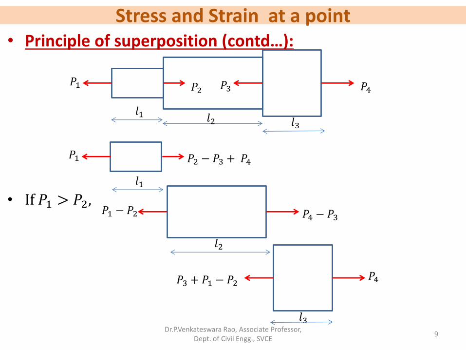
• When a number of loads are acting on a body, the resulting strain according to the principle of superposition will be the algebraic sum of the strains caused by the individual forces.
• For equilibrium, 𝑃1+𝑃3 = 𝑃2 + 𝑃4
• 𝛿𝑙 = 𝛿𝑙1 + δ𝑙2 + δ𝑙3
Dr.P.Venkateswara Rao, Associate Professor, Dept. of Civil Engg., SVCE
8
𝑙1 𝑙2
𝑙3
𝑃1 𝑃2 𝑃3 𝑃4
Stress and Strain at a point • Principle of superposition (contd…):
• If 𝑃1 > 𝑃2,
Dr.P.Venkateswara Rao, Associate Professor, Dept. of Civil Engg., SVCE
9
𝑙1 𝑙2 𝑙3
𝑃1 𝑃2 𝑃3 𝑃4
𝑃1 𝑃2 − 𝑃3 + 𝑃4
𝑙1
𝑙2
𝑃1 − 𝑃2 𝑃4 − 𝑃3
𝑃4 𝑃3 + 𝑃1 − 𝑃2
𝑙3
Stress and Strain at a point
Dr.P.Venkateswara Rao, Associate Professor, Dept. of Civil Engg., SVCE
10
𝑃1 𝑃2 − 𝑃3 + 𝑃4
𝑙1
• Principle of superposition (contd…):
𝑙2
𝑃1 − 𝑃2 𝑃4 − 𝑃3
𝑃4 𝑃3 + 𝑃1 − 𝑃2
𝑙3
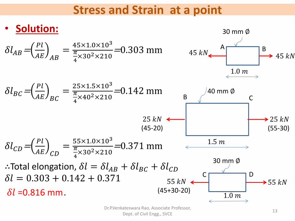
As per principle of superposition deformation of whole bar, 𝛿𝑙 = 𝛿𝑙𝐴𝐵 + 𝛿𝑙𝐵𝐶 + 𝛿𝑙𝐶𝐷
=𝑃1𝑙1
𝐴1𝐸+(𝑃1−𝑃2)𝑙2
𝐴2𝐸+𝑃4𝑙3
𝐴3𝐸
Stress and Strain at a point • Problem 1:
• A steel bar 3.5 m long is acted upon by forces as shown in Figure. Determine the value of P and the total elongation of the bar. Take E=210 kN/𝑚𝑚2
•
Dr.P.Venkateswara Rao, Associate Professor, Dept. of Civil Engg., SVCE
11
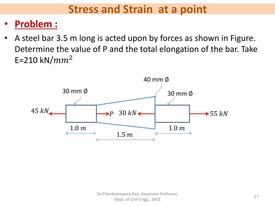
45 𝑘𝑁 𝑃 30 𝑘𝑁 55 𝑘𝑁
1.0 𝑚 1.5 𝑚
1.0 𝑚
30 mm ∅
40 mm ∅
30 mm ∅
Stress and Strain at a point
• Solution:
As per principle of superposition, 𝛿𝑙 = 𝛿𝑙𝐴𝐵 + 𝛿𝑙𝐵𝐶 + 𝛿𝑙𝐶𝐷
Dr.P.Venkateswara Rao, Associate Professor, Dept. of Civil Engg., SVCE
Dr.P.Venkateswara Rao, Associate Professor, Dept. of Civil Engg., SVCE
16
130 𝑘𝑁 130 𝑘𝑁
0.8 𝑚
25 mm ∅
A B
70𝑘𝑁 70 𝑘𝑁
1.6 𝑚
30 mm ∅
50 𝑘𝑁 50 𝑘𝑁
0.4 𝑚
20 mm ∅
B C
C D
Stress and Strain at a point • Problem :
• A steel bar 3.5 m long is acted upon by forces as shown in Figure. Determine the value of P and the total elongation of the bar. Take E=210 kN/𝑚𝑚2
Dr.P.Venkateswara Rao, Associate Professor, Dept. of Civil Engg., SVCE
17
45 𝑘𝑁 𝑃 30 𝑘𝑁 55 𝑘𝑁
1.0 𝑚 1.5 𝑚
1.0 𝑚
30 mm ∅
40 mm ∅
30 mm ∅
Stress and Strain at a point
Dr.P.Venkateswara Rao, Associate Professor, Dept. of Civil Engg., SVCE
18
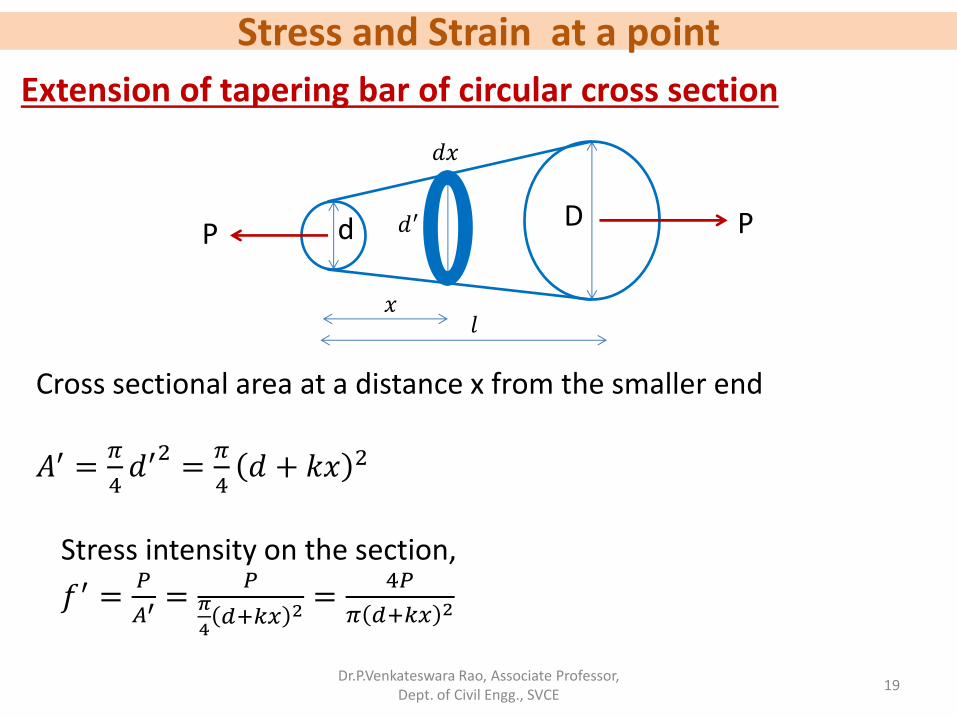
Extension of tapering bar of circular cross section
Consider an elemental length 𝑑𝑥 of the bar at a distance 𝑥 from the smaller end. Let the diameter of the bar be 𝑑′ at distance 𝑥 from the smaller end.
𝑑′ = d +𝐷 − 𝑑
𝐿𝑥
= 𝑑 + 𝑘𝑥
P P d D
𝑙
𝑑′
𝑑𝑥
𝑥
Stress and Strain at a point
Dr.P.Venkateswara Rao, Associate Professor, Dept. of Civil Engg., SVCE
19
Extension of tapering bar of circular cross section
Cross sectional area at a distance x from the smaller end
𝐴′ =𝜋
4𝑑′2=𝜋
4𝑑 + 𝑘𝑥 2
Stress intensity on the section,
𝑓′ =𝑃
𝐴′=
𝑃𝜋
4𝑑+𝑘𝑥 2
=4𝑃
𝜋 𝑑+𝑘𝑥 2
P P d D
𝑙
𝑑′
𝑑𝑥
𝑥
Stress and Strain at a point
Dr.P.Venkateswara Rao, Associate Professor, Dept. of Civil Engg., SVCE
20
Extension of tapering bar of circular cross section
Strain =𝑒′ =𝑓′
𝐸=
4𝑃
𝜋𝐸 𝑑+𝑘𝑥 2
Extension of the elemental length 𝑑𝑥, 𝛿𝑙 = 𝑒′𝑑𝑥
=4𝑃
𝜋𝐸 𝑑+𝑘𝑥 2 𝑑𝑥
P P d D
𝑙
𝑑′
𝑑𝑥
𝑥
Stress and Strain at a point
Dr.P.Venkateswara Rao, Associate Professor, Dept. of Civil Engg., SVCE
21
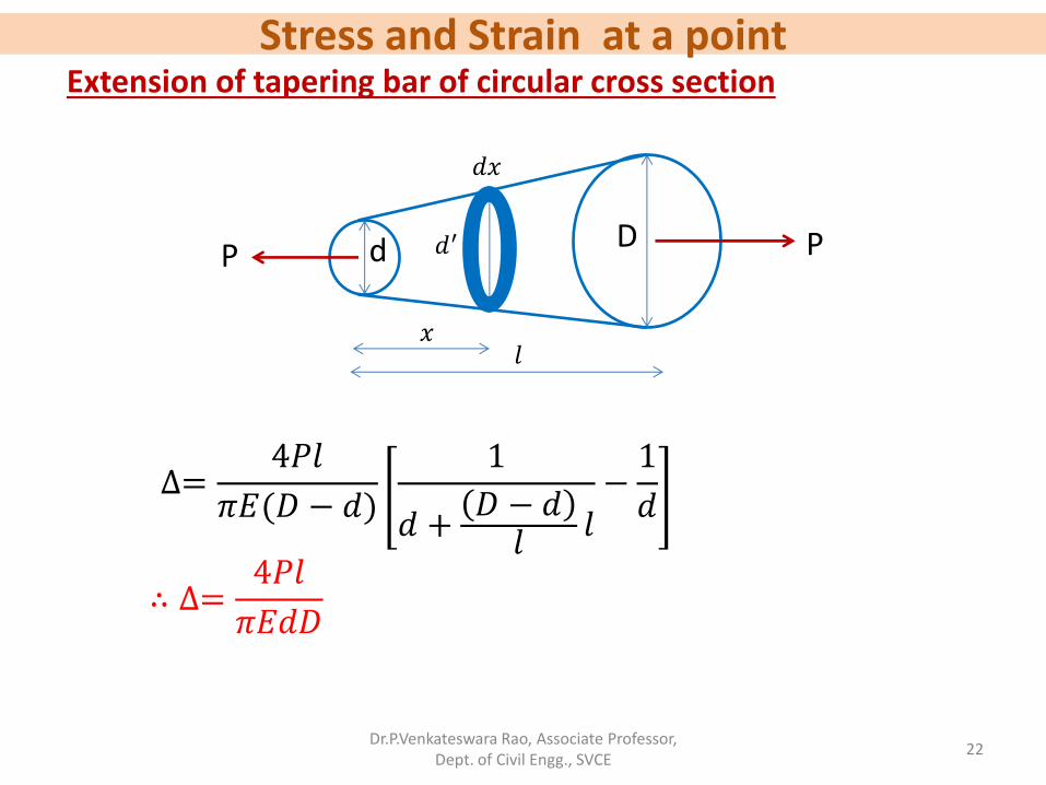
Extension of tapering bar of circular cross section
Extension of the whole bar, ∆=4𝑃
𝜋𝐸
𝑑𝑥
𝑑 + 𝑘𝑥 2
𝑙
0
=4𝑃𝑙
𝜋𝐸(𝐷 − 𝑑)
1
𝑑 + 𝑘𝑙−1
𝑑
0
𝑙
=4𝑃
𝜋𝐸×1
𝑘
1
𝑑 + 𝑘𝑥
P P d D
𝑙
𝑑′
𝑑𝑥
𝑥
Stress and Strain at a point
Dr.P.Venkateswara Rao, Associate Professor, Dept. of Civil Engg., SVCE
22
Extension of tapering bar of circular cross section
∆=4𝑃𝑙
𝜋𝐸(𝐷 − 𝑑)
1
𝑑 +𝐷 − 𝑑𝑙
𝑙−1
𝑑
∴ ∆=4𝑃𝑙
𝜋𝐸𝑑𝐷
P P d D
𝑙
𝑑′
𝑑𝑥
𝑥
Stress and Strain at a point
Dr.P.Venkateswara Rao, Associate Professor, Dept. of Civil Engg., SVCE
23
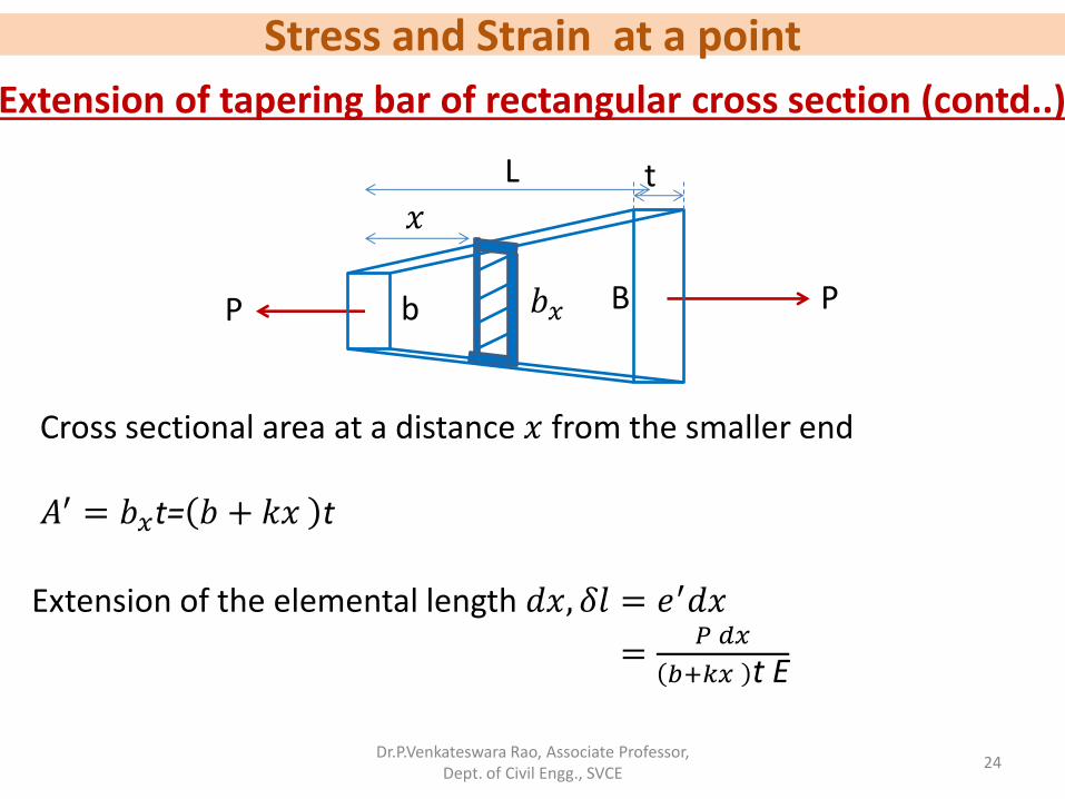
Extension of tapering bar of rectangular cross section
Consider an elemental length 𝑑𝑥 of the bar at a distance 𝑥 from the smaller end. Let the width of the bar be 𝑏𝑥 at distance 𝑥 from the smaller end.
𝑏𝑥 = b +𝐵 − 𝑏
𝐿𝑥
= 𝑏 + 𝑘𝑥
P P b B
t L
𝑥
𝑏𝑥
Stress and Strain at a point
Dr.P.Venkateswara Rao, Associate Professor, Dept. of Civil Engg., SVCE
24
Extension of tapering bar of rectangular cross section (contd..)
Cross sectional area at a distance 𝑥 from the smaller end 𝐴′ = 𝑏𝑥t= 𝑏 + 𝑘𝑥 t
P P b B
t L
𝑥
𝑏𝑥
Extension of the elemental length 𝑑𝑥, 𝛿𝑙 = 𝑒′𝑑𝑥
=𝑃 𝑑𝑥
𝑏+𝑘𝑥 t E
Stress and Strain at a point
Dr.P.Venkateswara Rao, Associate Professor, Dept. of Civil Engg., SVCE
25
Extension of tapering bar of rectangular cross section (contd..)
P P b B
t L
𝑥
𝑏𝑥
Extension of the whole bar, ∆=𝑃
𝑡𝐸
𝑑𝑥
𝑏 + 𝑘𝑥
𝑙
0
=𝑃
𝑡𝐸
1
𝑘log𝑒 𝑏 + 𝑘𝑥
0
𝐿
=𝑃
𝑡𝐸
1
𝑘log𝑒 𝑏 + 𝑘𝐿 − log𝑒 𝑏
Stress and Strain at a point
Dr.P.Venkateswara Rao, Associate Professor, Dept. of Civil Engg., SVCE
26
Extension of tapering bar of rectangular cross section (contd..)
P P b B
t L
𝑥
𝑏𝑥
∆=𝑃
𝑡𝐸
1
𝐵 − 𝑏𝐿
log𝑒
𝑏 +𝐵 − 𝑏𝐿 𝐿
𝑏
∴ ∆=𝑷𝑳
𝒕𝑬 𝑩 − 𝒃𝐥𝐨𝐠𝒆
𝑩
𝒃
Stress and Strain at a point
Dr.P.Venkateswara Rao, Associate Professor, Dept. of Civil Engg., SVCE
27
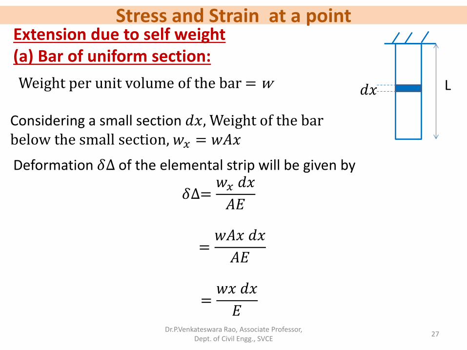
Extension due to self weight (a) Bar of uniform section: L 𝑑𝑥 Weight per unit volume of the bar = w
Considering a small section 𝑑𝑥, Weight of the bar below the small section, 𝑤𝑥 = 𝑤𝐴𝑥
Deformation 𝛿∆ of the elemental strip will be given by
𝛿∆=𝑤𝑥 𝑑𝑥
𝐴𝐸
=𝑤𝐴𝑥 𝑑𝑥
𝐴𝐸
=𝑤𝑥 𝑑𝑥
𝐸
Stress and Strain at a point
Dr.P.Venkateswara Rao, Associate Professor, Dept. of Civil Engg., SVCE
28
Extension due to self weight (a) Bar of uniform section (contd…):
L 𝑑𝑥
Deformation ∆ of the whole bar is given by
∆=𝑤
𝐸 𝑥 𝑑𝑥
𝐿
0
Deformation 𝛿∆ of the elemental strip will be given by
𝛿∆=𝑤𝑥𝑑𝑥
𝐸
=𝑤
𝐸×𝑥2
2
0
L
∴ ∆=𝒘𝑳𝟐
𝟐𝑬
Stress and Strain at a point
Dr.P.Venkateswara Rao, Associate Professor, Dept. of Civil Engg., SVCE
29
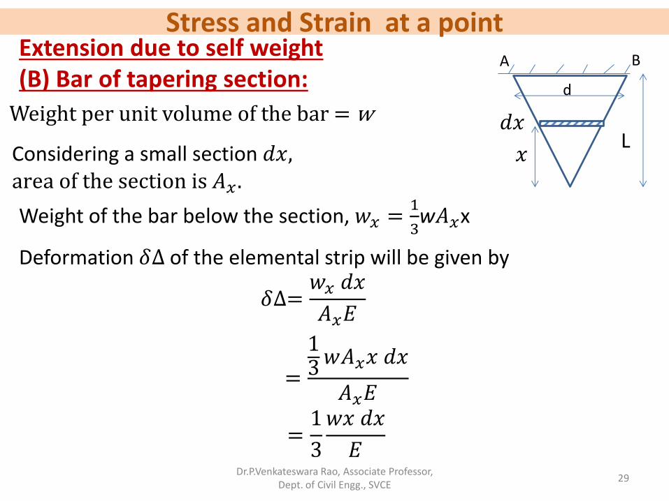
Extension due to self weight (B) Bar of tapering section:
Weight per unit volume of the bar = w
Considering a small section 𝑑𝑥, area of the section is 𝐴𝑥 .
Deformation 𝛿∆ of the elemental strip will be given by
𝛿∆=𝑤𝑥 𝑑𝑥
𝐴𝑥𝐸
=
13𝑤𝐴𝑥𝑥 𝑑𝑥
𝐴𝑥𝐸
=1
3
𝑤𝑥 𝑑𝑥
𝐸
A B
d
L 𝑥
𝑑𝑥
Weight of the bar below the section, 𝑤𝑥 =1
3w𝐴𝑥x
Stress and Strain at a point
Dr.P.Venkateswara Rao, Associate Professor, Dept. of Civil Engg., SVCE
30
Extension due to self weight (B) Bar of tapering section (contd…): A B
d
L 𝑥
𝑑𝑥 Deformation 𝛿∆ of the elemental strip will be given by
𝛿∆=1
3
𝑤𝑥𝑑𝑥
𝐸
Deformation ∆ of the whole bar is given by
∆=1
3
𝑤
𝐸 𝑥 𝑑𝑥
𝐿
0
=𝑤
3𝐸×𝑥2
2
0
L
∴ ∆=𝒘𝑳𝟐
𝟔𝑬
Stress and Strain at a point
Dr.P.Venkateswara Rao, Associate Professor, Dept. of Civil Engg., SVCE
31
Problem 1:
A steel plate of 20 mm thickness tapers uniformly from 100 mm to 50 mm in a length of 400 mm. What is the elongation of the plate, if an axial force of 80 kN acts on it. Take E = 200× 103 N/𝑚𝑚2.
Stress and Strain at a point
Dr.P.Venkateswara Rao, Associate Professor, Dept. of Civil Engg., SVCE
32
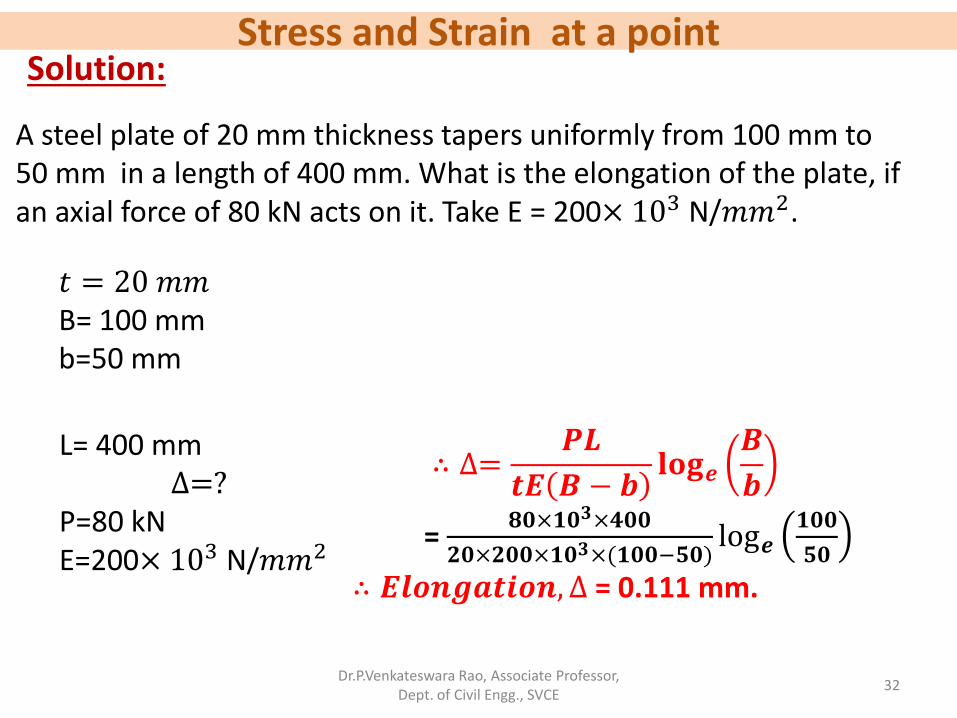
Solution:
∴ ∆=𝑷𝑳
𝒕𝑬 𝑩 − 𝒃𝐥𝐨𝐠𝒆
𝑩
𝒃
= 𝟖𝟎×𝟏𝟎𝟑×𝟒𝟎𝟎
𝟐𝟎×𝟐𝟎𝟎×𝟏𝟎𝟑×(𝟏𝟎𝟎−𝟓𝟎)log𝒆
𝟏𝟎𝟎
𝟓𝟎
∴ 𝑬𝒍𝒐𝒏𝒈𝒂𝒕𝒊𝒐𝒏, ∆ = 0.111 mm.
A steel plate of 20 mm thickness tapers uniformly from 100 mm to 50 mm in a length of 400 mm. What is the elongation of the plate, if an axial force of 80 kN acts on it. Take E = 200× 103 N/𝑚𝑚2.
𝑡 = 20 𝑚𝑚 B= 100 mm b=50 mm
L= 400 mm ∆=?
P=80 kN E=200× 103 N/𝑚𝑚2
Stress and Strain at a point
Dr.P.Venkateswara Rao, Associate Professor, Dept. of Civil Engg., SVCE
33
Problem 2:
A round bar of steel tapers uniformly from a diameter of 2.5 cm to 3.5 cm in length of 50 cm. If an axial force of 60000 N applied at each end, determine the elongation of the bar. Take E= 205 kN/𝑚𝑚2.
Stress and Strain at a point
Dr.P.Venkateswara Rao, Associate Professor, Dept. of Civil Engg., SVCE
34
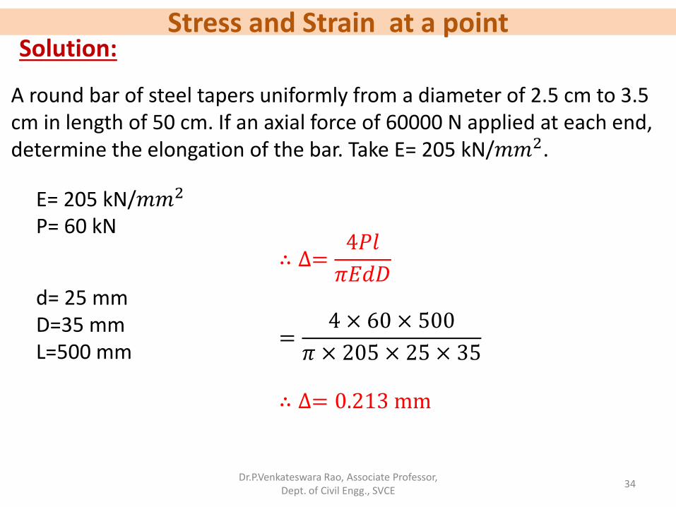
Solution:
A round bar of steel tapers uniformly from a diameter of 2.5 cm to 3.5 cm in length of 50 cm. If an axial force of 60000 N applied at each end, determine the elongation of the bar. Take E= 205 kN/𝑚𝑚2.
∴ ∆=4𝑃𝑙
𝜋𝐸𝑑𝐷
=4 × 60 × 500
𝜋 × 205 × 25 × 35
∴ ∆= 0.213 mm
E= 205 kN/𝑚𝑚2 P= 60 kN
d= 25 mm D=35 mm L=500 mm
Stress and Strain at a point
Dr.P.Venkateswara Rao, Associate Professor, Dept. of Civil Engg., SVCE
35
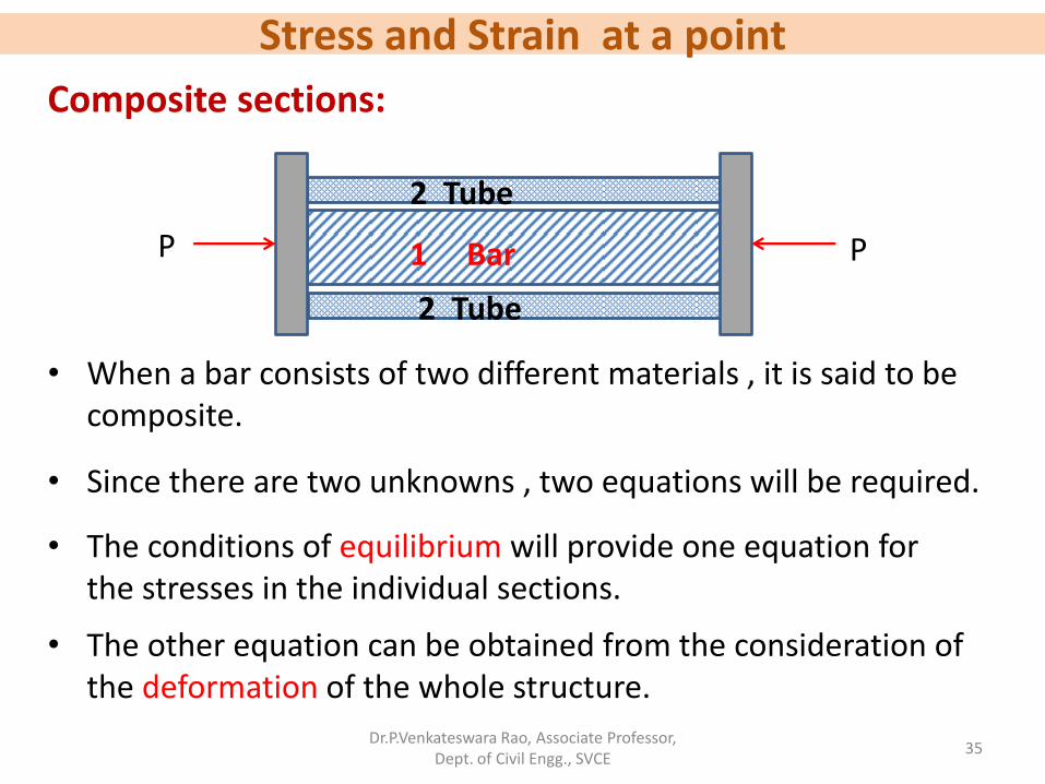
• When a bar consists of two different materials , it is said to be composite.
• Since there are two unknowns , two equations will be required.
• The conditions of equilibrium will provide one equation for the stresses in the individual sections.
• The other equation can be obtained from the consideration of the deformation of the whole structure.
P P 1 Bar
2 Tube
2 Tube
Composite sections:
Stress and Strain at a point
Dr.P.Venkateswara Rao, Associate Professor, Dept. of Civil Engg., SVCE
36
• Solid bar enclosed in the hollow tube and subjected to a compressive force P through rigid collars as shown in Fig.
• From the equilibrium equation, 𝑃1 + 𝑃2 = P −− −(1)
• Since the whole assembly is composite, the deformation of the bar is equal to deformation of tube.
• Therefore, ∆1= ∆2 𝑃1𝑙
𝐴1𝐸1=𝑃2𝑙
𝐴2𝐸2 −−−− −(2)
P P 1 Bar
2 Tube
2 Tube
Composite sections (contd…):
Stress and Strain at a point
Dr.P.Venkateswara Rao, Associate Professor, Dept. of Civil Engg., SVCE
37
𝑃1 + 𝑃2 = P −− −(1)
• By solving (1) & (2), one can find 𝑃1 and 𝑃2
𝑃1𝑙
𝐴1𝐸1=𝑃2𝑙
𝐴2𝐸2 −−−−−(2)
P P 1 Bar
2 Tube
2 Tube
Composite sections (contd…):
Stress and Strain at a point
Dr.P.Venkateswara Rao, Associate Professor, Dept. of Civil Engg., SVCE
38
Problem:
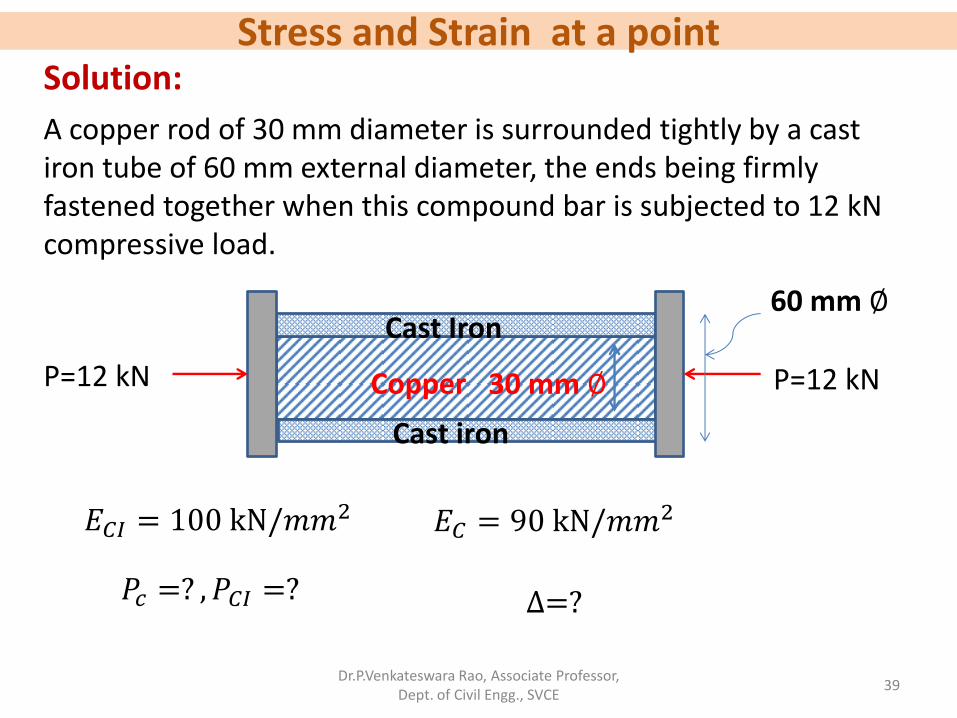
A copper rod of 30 mm diameter is surrounded tightly by a cast iron tube of 60 mm external diameter, the ends being firmly fastened together when this compound bar is subjected to 12 kN compressive load, what will be the share of load carried by copper rod and cast iron tube ? How much will be the shortening of the bar in 1m length. Assume 𝐸𝐶𝐼 = 100 kN/𝑚𝑚
2, 𝐸𝐶 = 90 kN/𝑚𝑚2
Stress and Strain at a point
Dr.P.Venkateswara Rao, Associate Professor, Dept. of Civil Engg., SVCE
39
Solution:
A copper rod of 30 mm diameter is surrounded tightly by a cast iron tube of 60 mm external diameter, the ends being firmly fastened together when this compound bar is subjected to 12 kN compressive load.
P=12 kN P=12 kN Copper
Cast Iron
Cast iron
30 mm ∅
60 mm ∅
𝑃𝑐 =? , 𝑃𝐶𝐼 =? ∆=?
𝐸𝐶𝐼 = 100 kN/𝑚𝑚2 𝐸𝐶 = 90 kN/𝑚𝑚
2
Stress and Strain at a point
Dr.P.Venkateswara Rao, Associate Professor, Dept. of Civil Engg., SVCE
40
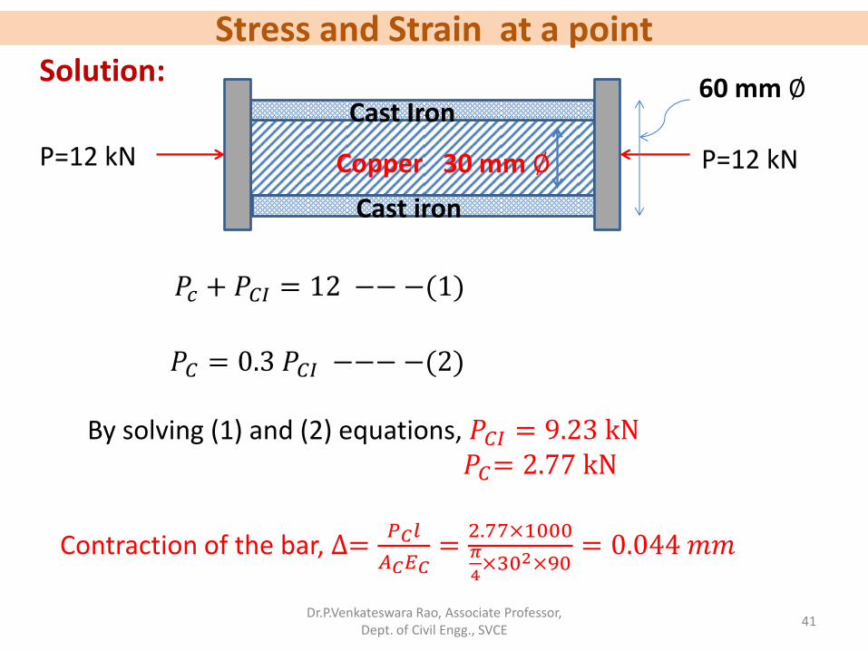
Solution:
P=12 kN P=12 kN Copper
Cast Iron
Cast iron
30 mm ∅
60 mm ∅
𝑃𝑐 + 𝑃𝐶𝐼 = P
𝑃𝐶𝑙
𝐴𝐶𝐸𝐶=𝑃𝐶𝐼𝑙
𝐴𝐶𝐼𝐸𝐶𝐼
𝑃𝑐 + 𝑃𝐶𝐼 = 12 −− −(1)
𝑃𝐶𝑙𝜋4× 302 × 90
=𝑃𝐶𝐼𝑙
𝜋4× (602 − 302) × 100
𝑃𝐶 = 0.3 𝑃𝐶𝐼 −−− −(2)
Stress and Strain at a point
Dr.P.Venkateswara Rao, Associate Professor, Dept. of Civil Engg., SVCE
41
Solution:
P=12 kN P=12 kN Copper
Cast Iron
Cast iron
30 mm ∅
60 mm ∅
𝑃𝑐 + 𝑃𝐶𝐼 = 12 −− −(1)
𝑃𝐶 = 0.3 𝑃𝐶𝐼 −−− −(2)
By solving (1) and (2) equations, 𝑃𝐶𝐼 = 9.23 kN 𝑃𝐶= 2.77 kN
Contraction of the bar, ∆=𝑃𝐶𝑙
𝐴𝐶𝐸𝐶=2.77×1000𝜋
4×302×90
= 0.044 𝑚𝑚
Stress and Strain at a point
Dr.P.Venkateswara Rao, Associate Professor, Dept. of Civil Engg., SVCE
42
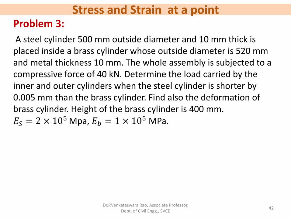
Problem 3:
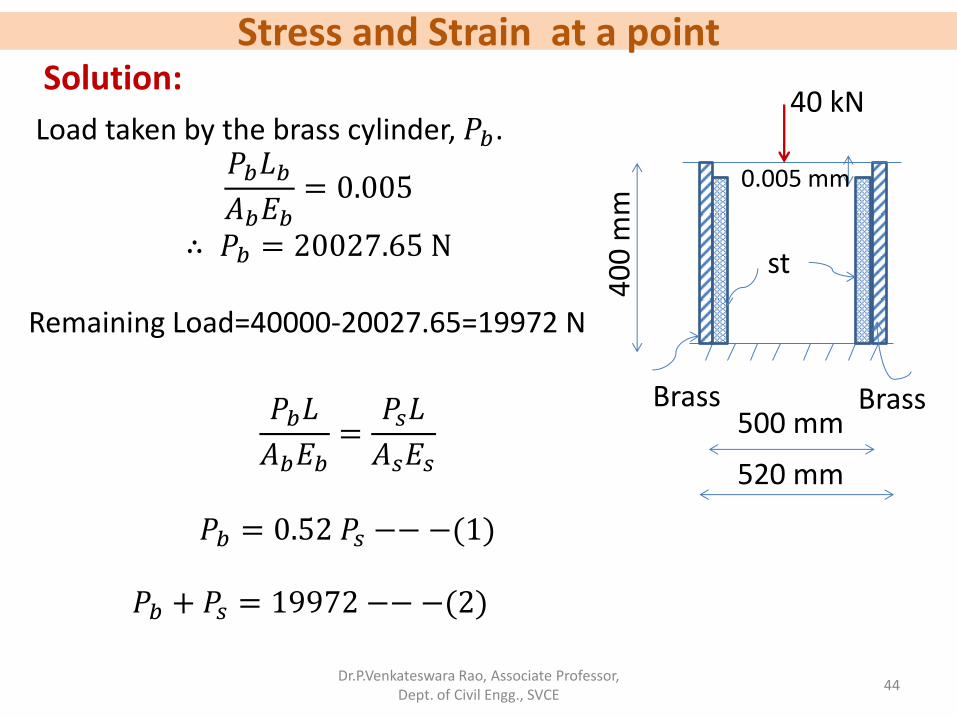
A steel cylinder 500 mm outside diameter and 10 mm thick is placed inside a brass cylinder whose outside diameter is 520 mm and metal thickness 10 mm. The whole assembly is subjected to a compressive force of 40 kN. Determine the load carried by the inner and outer cylinders when the steel cylinder is shorter by 0.005 mm than the brass cylinder. Find also the deformation of brass cylinder. Height of the brass cylinder is 400 mm. 𝐸𝑆 = 2 × 10
5 Mpa, 𝐸𝑏 = 1 × 10⁵ MPa.
Stress and Strain at a point
Dr.P.Venkateswara Rao, Associate Professor, Dept. of Civil Engg., SVCE
43
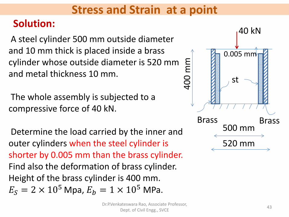
Solution:
A steel cylinder 500 mm outside diameter and 10 mm thick is placed inside a brass cylinder whose outside diameter is 520 mm and metal thickness 10 mm. The whole assembly is subjected to a compressive force of 40 kN. Determine the load carried by the inner and outer cylinders when the steel cylinder is shorter by 0.005 mm than the brass cylinder. Find also the deformation of brass cylinder. Height of the brass cylinder is 400 mm. 𝐸𝑆 = 2 × 10
5 Mpa, 𝐸𝑏 = 1 × 10⁵ MPa.
40
0 m
m
40 kN
0.005 mm
st
Brass Brass 500 mm
520 mm
Stress and Strain at a point
Dr.P.Venkateswara Rao, Associate Professor, Dept. of Civil Engg., SVCE
44
Solution:
Load taken by the brass cylinder, 𝑃𝑏. 𝑃𝑏𝐿𝑏𝐴𝑏𝐸𝑏
= 0.005
∴ 𝑃𝑏 = 20027.65 N Remaining Load=40000-20027.65=19972 N
40
0 m
m
40 kN
0.005 mm
st
Brass Brass 500 mm
520 mm
𝑃𝑏𝐿
𝐴𝑏𝐸𝑏=𝑃𝑠𝐿
𝐴𝑠𝐸𝑠
𝑃𝑏 = 0.52 𝑃𝑠 −−−(1)
𝑃𝑏 + 𝑃𝑠 = 19972 −− −(2)
Stress and Strain at a point
Dr.P.Venkateswara Rao, Associate Professor, Dept. of Civil Engg., SVCE
45
Solution:
40
0 m
m
40 kN
0.005 mm
st
Brass Brass 500 mm
520 mm
𝑃𝑏 = 0.52 𝑃𝑠 −−−(1)
𝑃𝑏 + 𝑃𝑠 = 19972 −− −(2)
By solving (1) and (2), 𝑃𝑏 = 6832.52 N 𝑃𝑠 = 13139.47 N
Deformation of brass cylinder,
∆𝑏=𝑃𝑏𝑙𝑏
𝐴𝑏𝐸𝑏=
6832.52×400
16022.123×1×105= 1.706 × 10⁻³ mm
Total deformation of brass cylinder=0.005+0.001706=0.006706 mm
Stress and Strain at a point
Dr.P.Venkateswara Rao, Associate Professor, Dept. of Civil Engg., SVCE
46
• When a material undergoes change in the temperature, its length is varied and if the material is free to do so, no stresses are developed.
Temperature stresses:
• If the material is constrained so that no change in length is permissible, stresses are developed in the material.
• These developed stresses are temperature stresses and may be tensile or compressive depending upon whether contraction is checked or extension is checked.
Stress and Strain at a point
Dr.P.Venkateswara Rao, Associate Professor, Dept. of Civil Engg., SVCE
47
• Let us consider a bar of length L, snuggly fitting between two walls or supports.
• If the temperature is increased through 𝑡0 C, the bar will be increased in length by an amount ∆= 𝐿𝛼𝑡,
Where 𝛼 is the coefficient of thermal expansion.
Temperature stresses (contd…):
• Due to external conditions, the bar is not free to expand by the amount ∆ and therefore from Hooke’s law,
∆=𝑓𝐿
𝐸, where 𝑓 is the temperature stress.
𝑓 =∆𝐸
𝐿=𝐿𝛼𝑡 𝐸
𝐿= α𝑡𝐸
• ∴ 𝑓 = 𝛼𝑡𝐸 (Compressive)
Stress and Strain at a point
Dr.P.Venkateswara Rao, Associate Professor, Dept. of Civil Engg., SVCE
48
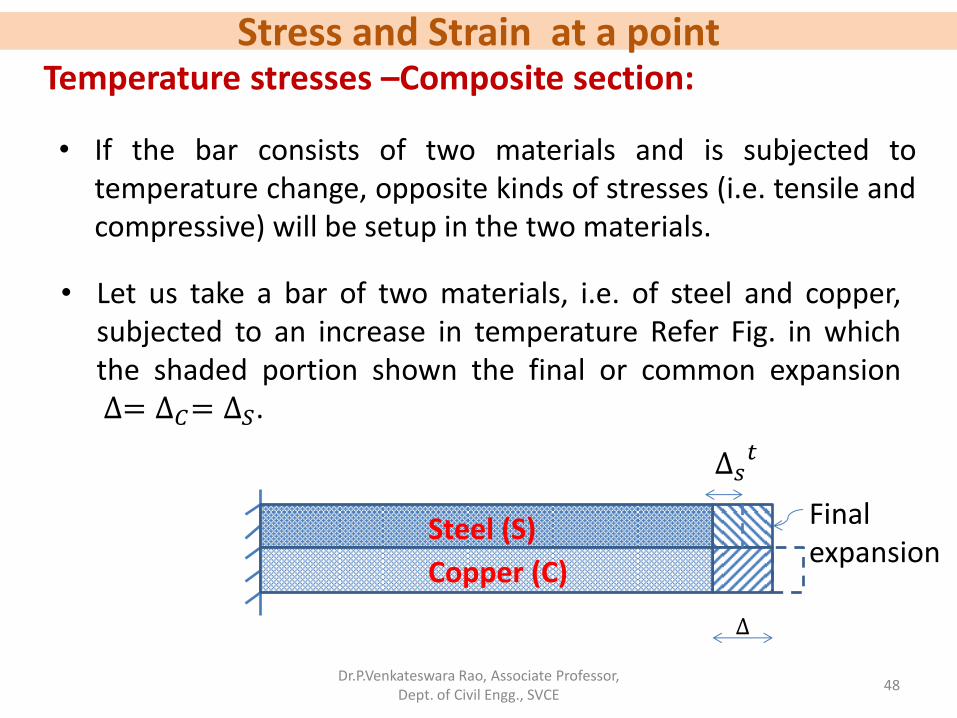
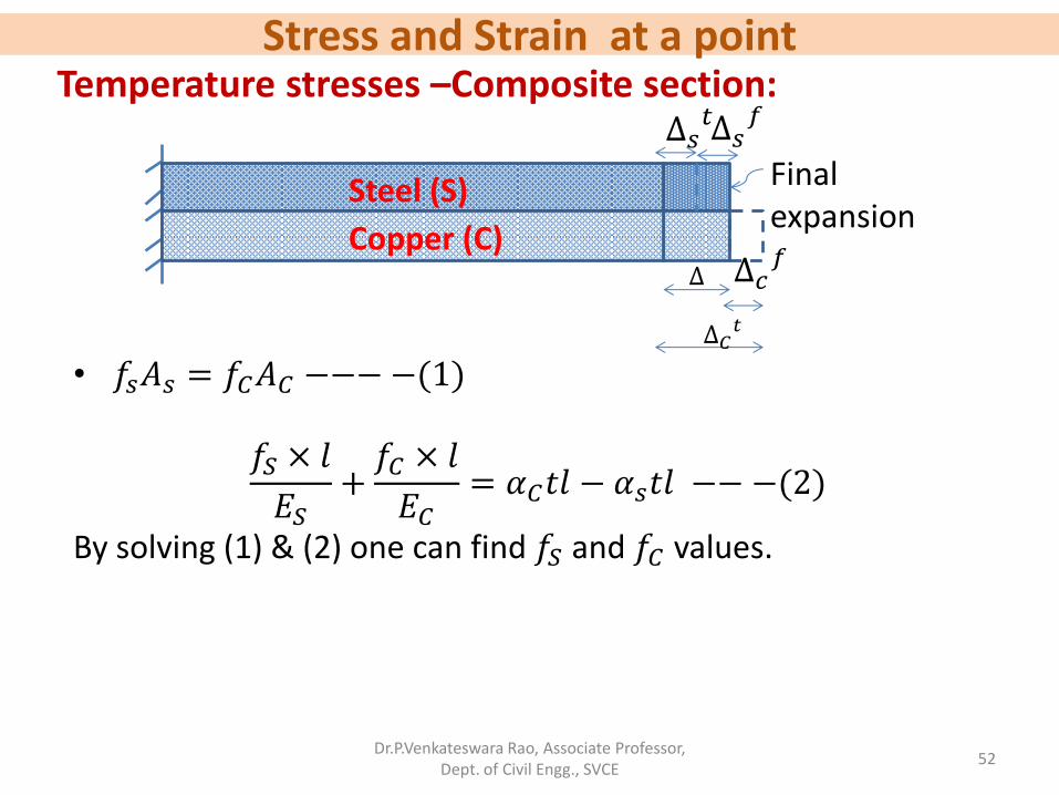
• If the bar consists of two materials and is subjected to temperature change, opposite kinds of stresses (i.e. tensile and compressive) will be setup in the two materials.
Temperature stresses –Composite section:
• Let us take a bar of two materials, i.e. of steel and copper, subjected to an increase in temperature Refer Fig. in which the shaded portion shown the final or common expansion ∆= ∆𝐶= ∆𝑆.
∆
Steel (S)
Copper (C)
Final expansion
∆𝑠𝑡
Stress and Strain at a point
Dr.P.Venkateswara Rao, Associate Professor, Dept. of Civil Engg., SVCE
49
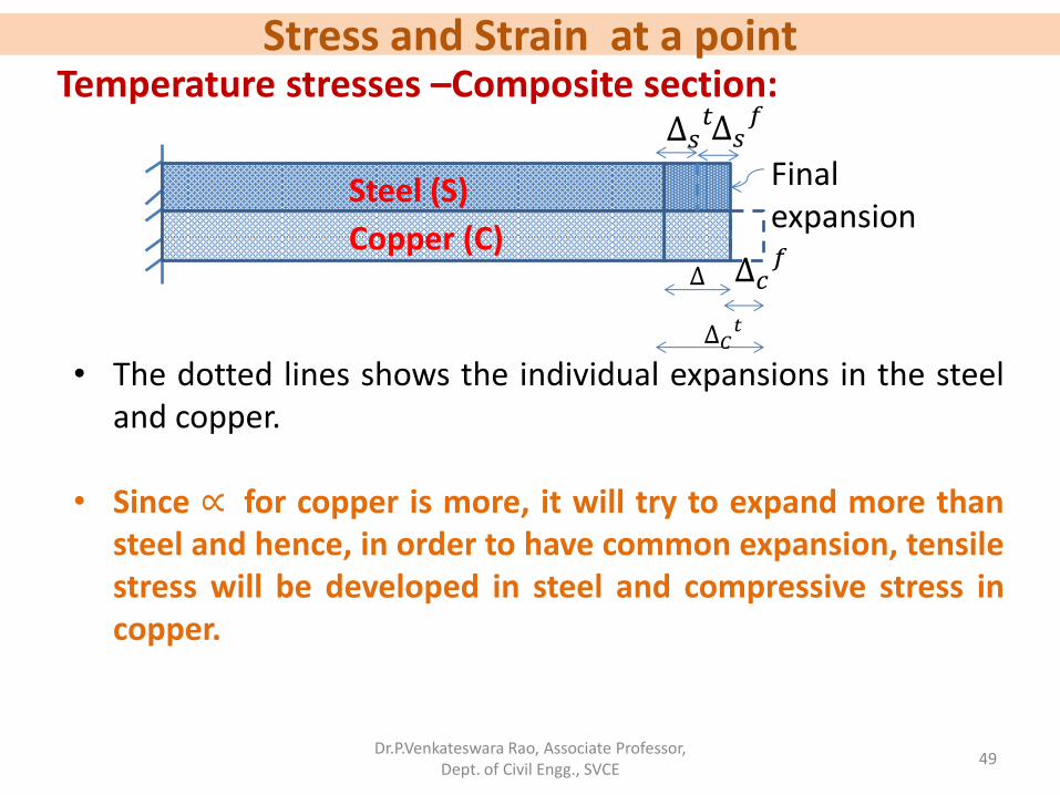
Temperature stresses –Composite section:
• The dotted lines shows the individual expansions in the steel and copper.
• Since ∝ for copper is more, it will try to expand more than
steel and hence, in order to have common expansion, tensile stress will be developed in steel and compressive stress in copper.
∆
Steel (S)
Copper (C)
Final expansion
∆𝑠𝑡
∆𝐶𝑡
∆𝑠𝑓
∆𝑐𝑓
Stress and Strain at a point
Dr.P.Venkateswara Rao, Associate Professor, Dept. of Civil Engg., SVCE
50
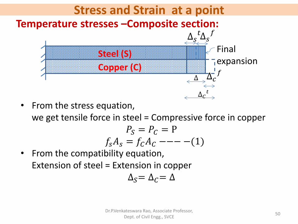
Temperature stresses –Composite section:
• From the stress equation, we get tensile force in steel = Compressive force in copper
𝑃𝑆 = 𝑃𝐶 = P 𝑓𝑠𝐴𝑠 = 𝑓𝐶𝐴𝐶 −−−−(1) • From the compatibility equation, Extension of steel = Extension in copper
∆𝑆= ∆𝐶= ∆
∆
Steel (S)
Copper (C)
Final expansion
∆𝑠𝑡
∆𝐶𝑡
∆𝑠𝑓
∆𝑐𝑓
Stress and Strain at a point
Dr.P.Venkateswara Rao, Associate Professor, Dept. of Civil Engg., SVCE
51
Temperature stresses –Composite section:
• From the above Fig.,
∆𝑆= ∆𝑆𝑡 + ∆𝑆
𝑓
∆𝐶= ∆𝐶𝑡 − ∆𝐶
𝑓 ∆𝑆
𝑡 + ∆𝑆𝑓= ∆𝐶
𝑡 − ∆𝐶𝑓
∆𝑆𝑓 + ∆𝐶
𝑓= ∆𝐶𝑡 − ∆𝑆
𝑡 𝑓𝑆 × 𝑙
𝐸𝑆+𝑓𝐶 × 𝑙
𝐸𝐶= 𝛼𝐶𝑡𝑙 − 𝛼𝑠𝑡𝑙 −− −(2)
∆
Steel (S)
Copper (C)
Final expansion
∆𝑠𝑡
∆𝐶𝑡
∆𝑠𝑓
∆𝑐𝑓
Stress and Strain at a point
Dr.P.Venkateswara Rao, Associate Professor, Dept. of Civil Engg., SVCE
52
Temperature stresses –Composite section:
• 𝑓𝑠𝐴𝑠 = 𝑓𝐶𝐴𝐶 −−−−(1)
𝑓𝑆 × 𝑙
𝐸𝑆+𝑓𝐶 × 𝑙
𝐸𝐶= 𝛼𝐶𝑡𝑙 − 𝛼𝑠𝑡𝑙 −− −(2)
By solving (1) & (2) one can find 𝑓𝑆 and 𝑓𝐶 values.
∆
Steel (S)
Copper (C)
Final expansion
∆𝑠𝑡
∆𝐶𝑡
∆𝑠𝑓
∆𝑐𝑓
Stress and Strain at a point
Dr.P.Venkateswara Rao, Associate Professor, Dept. of Civil Engg., SVCE
53
Problem:
A steel tube of 30 mm external diameter and 25 mm internal diameter encloses a copper rod of 20 mm diameter to which it is rigidly connected at each end. If at the temperature of 150𝐶, there is no longitudinal stress, calculate the stresses in the rod and the tube when the temperature is raised to 1150𝐶. 𝐸𝑆 = 200 kN/𝑚𝑚
2, 𝐸𝐶 = 100 kN/𝑚𝑚
2, 𝛼𝑆 = 6 × 10⁻⁶/0C, 𝛼𝐶 = 10 × 10
−6/0C
Stress and Strain at a point
Dr.P.Venkateswara Rao, Associate Professor, Dept. of Civil Engg., SVCE
54
Solution:
A steel tube of 30 mm external diameter and 25 mm internal diameter encloses a copper rod of 20 mm diameter to which it is rigidly connected at each end.
𝐴𝑆 =𝜋
4302 − 252 = 215.98 𝑚𝑚2
𝐴𝐶 =𝜋
4202 = 314.16 𝑚𝑚2
Copper rod
Steel tube
Steel tube
20 mm ∅
30 mm ∅
25 mm ∅
Stress and Strain at a point
Dr.P.Venkateswara Rao, Associate Professor, Dept. of Civil Engg., SVCE
55
Solution (contd…):
If at the temperature of 150𝐶, there is no longitudinal stress, calculate the stresses in the rod and the tube when the temperature is raised to 1150𝐶. 𝐸𝑆 = 200 kN/𝑚𝑚
2 , 𝐸𝐶 = 100 kN/𝑚𝑚2 , 𝛼𝑆 = 6 × 10
−6/0 C, 𝛼𝐶 = 10 × 10
−6/0C
Due to temperature raise, total tension in steel = total compression in copper
Dr.P.Venkateswara Rao, Associate Professor, Dept. of Civil Engg., SVCE
56
Solution (contd…):
Actual expansion of steel= Actual expansion of copper
𝑓𝑆 × 𝑙
𝐸𝑆+ 𝛼𝑠𝑡𝑙 = 𝛼𝐶𝑡𝑙 −
𝑓𝐶 × 𝑙
𝐸𝐶
𝑓𝑆𝐸𝑆+ 𝛼𝑠𝑡 = 𝛼𝐶𝑡 −
𝑓𝐶𝐸𝐶
1.455𝑓𝐶200 × 103
+ 6 × 10−6 × 100 = 10 × 10−6 × 100 −𝑓𝐶
100 × 103
𝒇𝑪 = 𝟐𝟑. 𝟏𝟔 𝑵/𝒎𝒎𝟐
𝒇𝑺 = 1.455𝑓𝐶 = 1.455 × 23.16 = 𝟑𝟑. 𝟔𝟗 𝑵/𝒎𝒎𝟐
∴Stress in copper rod=23.16 N/𝑚𝑚2 Stress in Steel tube= 33.69 N/𝑚𝑚2
Stress and Strain at a point
Dr.P.Venkateswara Rao, Associate Professor, Dept. of Civil Engg., SVCE
57
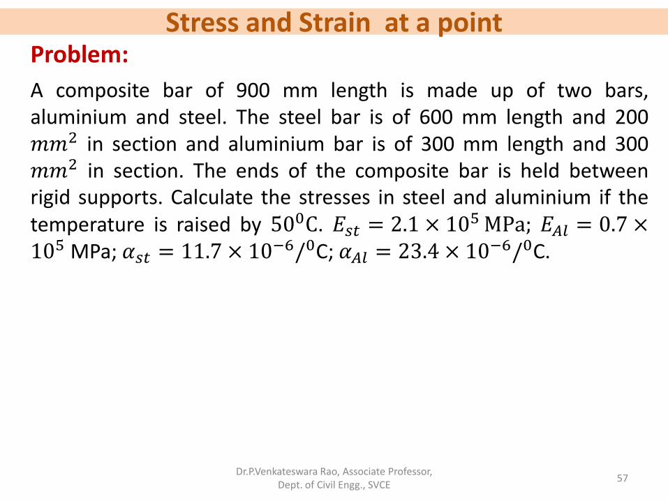
Problem:
A composite bar of 900 mm length is made up of two bars, aluminium and steel. The steel bar is of 600 mm length and 200 𝑚𝑚2 in section and aluminium bar is of 300 mm length and 300 𝑚𝑚2 in section. The ends of the composite bar is held between rigid supports. Calculate the stresses in steel and aluminium if the temperature is raised by 500C. 𝐸𝑠𝑡 = 2.1 × 10
5 MPa; 𝐸𝐴𝑙 = 0.7 ×10⁵ MPa; 𝛼𝑠𝑡 = 11.7 × 10
−6/0C; 𝛼𝐴𝑙 = 23.4 × 10⁻⁶/0C.
Stress and Strain at a point
Dr.P.Venkateswara Rao, Associate Professor, Dept. of Civil Engg., SVCE
58
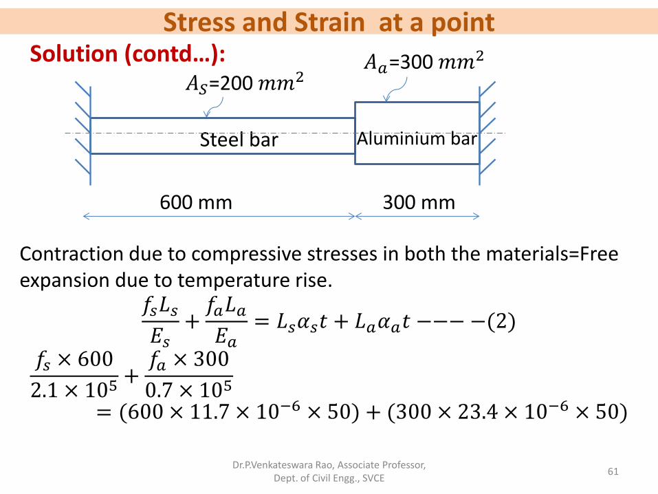
Solution:
A composite bar of 900 mm length is made up of two bars, aluminium and steel. The steel bar is of 600 mm length and 200 𝑚𝑚2 in section and aluminium bar is of 300 mm length and 300 𝑚𝑚2 in section. The ends of the composite bar is held between rigid supports.
Steel bar Aluminium bar
𝐴𝑆=200 𝑚𝑚2 𝐴𝑎=300 𝑚𝑚2
600 mm 300 mm
Stress and Strain at a point
Dr.P.Venkateswara Rao, Associate Professor, Dept. of Civil Engg., SVCE
59
Solution (contd…):
The temperature is raised by 500C. 𝐸𝑠𝑡 = 2.1 × 10⁵ MPa; 𝐸𝐴𝑙 =
Dr.P.Venkateswara Rao, Associate Professor, Dept. of Civil Engg., SVCE
63
Problem:
A steel rod of 20 mm diameter passes centrally through a tight fitting copper tube of external diameter 40 mm. The tube is closed with the help of rigid washers of negligible thickness and nuts threaded on the rod. The nuts are tightened till the compressive load on the tube is 50 kN as shown in Fig. Determine the stresses in the rod and tube, when the temperature of the assembly falls, by 50 K. Take E for steel and copper as 200 GPa and 100 GPa respectively. Take coefficient of expansion for steel and copper as 12 × 10−6/𝐾 and 18 × 10−6/𝐾 respectively.
Steel rod
Copper tube
Copper tube
20 mm ∅
40 mm ∅
50 kN 50 kN
Stress and Strain at a point
Dr.P.Venkateswara Rao, Associate Professor, Dept. of Civil Engg., SVCE
64
Problem:
A composite bar shown in Fig. is rigidly fixed at the ends. An axial pull of P=15 kN is applied at B at 100𝐶. Find the stresses in each
material at 800𝐶. 𝐸𝑠𝑡 = 210 kN
𝑚𝑚2, 𝐸𝐴𝑙 = 70 𝑘𝑁/𝑚𝑚
2 ; 𝛼𝑠𝑡 =
11 × 10−6/0C; 𝛼𝐴𝑙 = 24 × 10−6/0C.
Steel bar Aluminium bar
30 𝑚𝑚 ∅ 40 𝑚𝑚 ∅
100 mm 200 mm
15 kN
Stress and Strain at a point
Dr.P.Venkateswara Rao, Associate Professor, Dept. of Civil Engg., SVCE
65
Elastic Constants: E, C,K & 𝝁
∴ 𝑃𝑜𝑖𝑠𝑠𝑜𝑛′𝑠 𝑟𝑎𝑡𝑖,1
𝑚𝜇 =
𝐿𝑎𝑡𝑒𝑟𝑎𝑙 𝑠𝑡𝑟𝑎𝑖𝑛
𝐿𝑜𝑛𝑔𝑖𝑡𝑢𝑑𝑖𝑛𝑎𝑙 𝑠𝑡𝑟𝑎𝑖𝑛= Constant
∴ 𝐿𝑎𝑡𝑒𝑟𝑎𝑙 𝑠𝑡𝑟𝑎𝑖𝑛 =1
𝑚× 𝐿𝑜𝑛𝑔𝑖𝑡𝑢𝑑𝑖𝑛𝑎𝑙 𝑠𝑡𝑟𝑎𝑖𝑛
• Any direct stress produces a strain in its own direction and an opposite strain in every direction at right angles to this.
• The ratio of the lateral strain to the longitudinal strain is constant for a given material and is known as poisson’s ratio.
1
𝑚μ = 0.25 𝑡𝑜 0.42 −− −𝐹𝑜𝑟 𝑚𝑜𝑠𝑡 𝑜𝑓 𝑡ℎ𝑒 𝑚𝑒𝑡𝑎𝑙𝑠
1
𝑚μ = 0.45 𝑡𝑜 0.50 −− −𝐹𝑜𝑟 𝑟𝑢𝑏𝑏𝑒𝑟
Poisson’s ratio - Lateral Strain:
Stress and Strain at a point
Dr.P.Venkateswara Rao, Associate Professor, Dept. of Civil Engg., SVCE
66
Elastic Constants: E, C,K & 𝝁
For rectangular bar: V=Lbd
𝛿𝑉 = 𝛿𝐿 𝑏 𝑑 + L δ𝑏 𝑑 + L b δ𝑑 𝛿𝑉
𝑉=𝛿𝐿
𝐿+𝛿𝑏
𝑏+𝛿𝑑
𝑑
Volumetric strain, 𝑒𝑉 =𝛿𝑉
𝑉=𝑓
𝐸−1
𝑚
𝑓
𝐸−1
𝑚
𝑓
𝐸
=𝑓
𝐸1 −
2
𝑚
Single direct stress along the longitudinal axis:
P P
Stress and Strain at a point
Dr.P.Venkateswara Rao, Associate Professor, Dept. of Civil Engg., SVCE
67
Elastic Constants: E, C,K & 𝝁
For Circular bar:
V=𝜋
4𝑑2L
𝛿𝑉 =𝜋
4𝑑2𝛿𝐿 + 2
𝜋
4d δ𝑑 𝐿
𝛿𝑉
𝑉=𝛿𝐿
𝐿+ 2
𝛿𝑑
𝑑
Volumetric strain, 𝑒𝑉 =𝛿𝑉
𝑉=𝑓
𝐸−2
𝑚
𝑓
𝐸
=𝑓
𝐸1 −
2
𝑚
Single direct stress along the longitudinal axis:
P P
Stress and Strain at a point
Dr.P.Venkateswara Rao, Associate Professor, Dept. of Civil Engg., SVCE
68
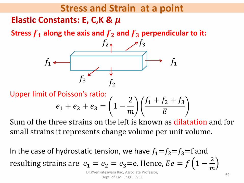
Elastic Constants: E, C,K & 𝝁
Longitudinal strain, 𝑒1 =𝑓1
𝐸−
𝑓2
𝑚𝐸−
𝑓3
𝑚𝐸
Similarly, 𝑒2 =𝑓2
𝐸−
𝑓1
𝑚𝐸−
𝑓3
𝑚𝐸
𝑒3 =𝑓3
𝐸−
𝑓1
𝑚𝐸−
𝑓2
𝑚𝐸
If some of the stresses are opposite sign, necessary change in the algebraic signs of the above expressions will have to be made.
Stress 𝒇𝟏 along the axis and 𝒇𝟐 and 𝒇𝟑 perpendicular to it:
𝑓1 𝑓1
𝑓2
𝑓2
𝑓3
𝑓3
Stress and Strain at a point
Dr.P.Venkateswara Rao, Associate Professor, Dept. of Civil Engg., SVCE
69
Elastic Constants: E, C,K & 𝝁
𝑒1 + 𝑒2 + 𝑒3 = 1 −2
𝑚
𝑓1 + 𝑓2 + 𝑓3𝐸
Sum of the three strains on the left is known as dilatation and for small strains it represents change volume per unit volume. In the case of hydrostatic tension, we have 𝑓1=𝑓2=𝑓3=f and
Stress 𝒇𝟏 along the axis and 𝒇𝟐 and 𝒇𝟑 perpendicular to it:
𝑓1 𝑓1
𝑓2
𝑓2
𝑓3
𝑓3
Upper limit of Poisson’s ratio:
Stress and Strain at a point
Dr.P.Venkateswara Rao, Associate Professor, Dept. of Civil Engg., SVCE
70
Elastic Constants: E, C,K & 𝝁
In the expression 𝐸𝑒 = 𝑓 1 −2
𝑚; E, e and f are positive
numbers and hence 1 −2
𝑚 must also be positive.
This limits the 1
𝑚 to a maximum value of 0.5.
∴ Maximum value of poisson’s ration =0.5.
Stress 𝒇𝟏 along the axis and 𝒇𝟐 and 𝒇𝟑 perpendicular to it:
𝑓1 𝑓1
𝑓2
𝑓2
𝑓3
𝑓3
Stress and Strain at a point
Dr.P.Venkateswara Rao, Associate Professor, Dept. of Civil Engg., SVCE
71
Elastic Constants: E, C,K & 𝝁
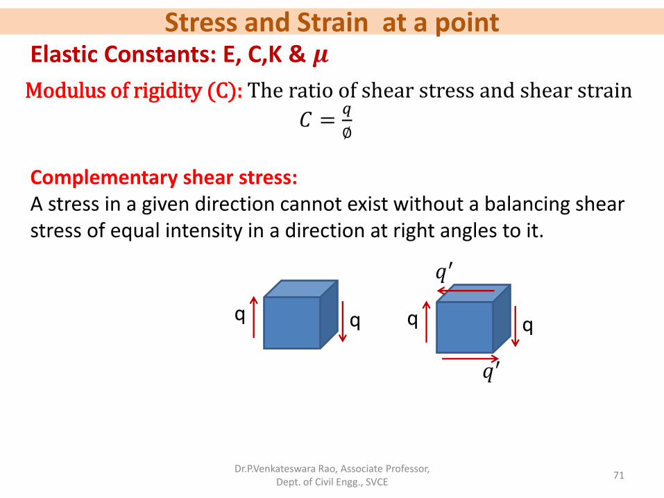
Modulus of rigidity (C): The ratio of shear stress and shear strain
𝐶 =𝑞
∅
Complementary shear stress: A stress in a given direction cannot exist without a balancing shear stress of equal intensity in a direction at right angles to it.
q q q q
𝑞′
𝑞′
Stress and Strain at a point
Dr.P.Venkateswara Rao, Associate Professor, Dept. of Civil Engg., SVCE
72
Elastic Constants: E, C,K & 𝝁
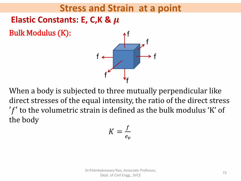
Bulk Modulus (K): When a body is subjected to three mutually perpendicular like direct stresses of the equal intensity, the ratio of the direct stress ′𝑓′ to the volumetric strain is defined as the bulk modulus ‘K’ of the body
𝐾 =𝑓
𝑒𝑣
f
f
f f
f
f
Stress and Strain at a point
Dr.P.Venkateswara Rao, Associate Professor, Dept. of Civil Engg., SVCE
73
Relation between elastic constants:
Relation between E and K: Let us take a cube of side ‘L’ be subjected to three mutually perpendicular like stresses of equal intensity ‘f ’. By the definition of the bulk modulus
𝐾 =𝑓
𝑒𝑣
Or 𝑒𝑣 =𝛿𝑉
𝑉=𝑓
𝐾−−−−(1)
f
f
f f
f
f
Stress and Strain at a point
Dr.P.Venkateswara Rao, Associate Professor, Dept. of Civil Engg., SVCE
74
Relation between elastic constants:
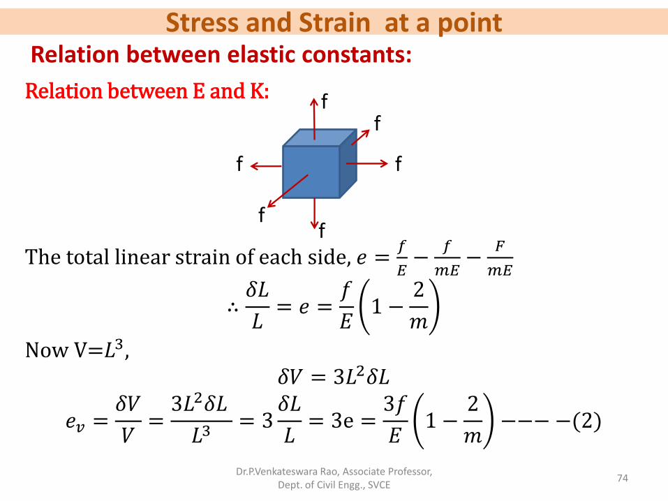
Relation between E and K:
The total linear strain of each side, 𝑒 =𝑓
𝐸−
𝑓
𝑚𝐸−
𝐹
𝑚𝐸
∴𝛿𝐿
𝐿= 𝑒 =
𝑓
𝐸1 −
2
𝑚
Now V=𝐿3, 𝛿𝑉 = 3𝐿2𝛿𝐿
𝑒𝑣 =𝛿𝑉
𝑉=3𝐿2𝛿𝐿
𝐿3= 3
𝛿𝐿
𝐿= 3e =
3𝑓
𝐸1 −
2
𝑚−−−−(2)
f
f
f f
f
f
Stress and Strain at a point
Dr.P.Venkateswara Rao, Associate Professor, Dept. of Civil Engg., SVCE
75
Relation between elastic constants:
Relation between E and K:
𝑒𝑣 =𝑓
𝐾−−−−(1)
𝑒𝑣 =3𝑓
𝐸1 −
2
𝑚−−−−(2)
Equating (1) and (2), 𝑓
𝐾=3𝑓
𝐸1 −
2
𝑚
∴ 𝑬 = 𝟑𝑲 𝟏 −𝟐
𝒎
f
f
f f
f
f
Stress and Strain at a point
Dr.P.Venkateswara Rao, Associate Professor, Dept. of Civil Engg., SVCE
76
Relation between elastic constants:
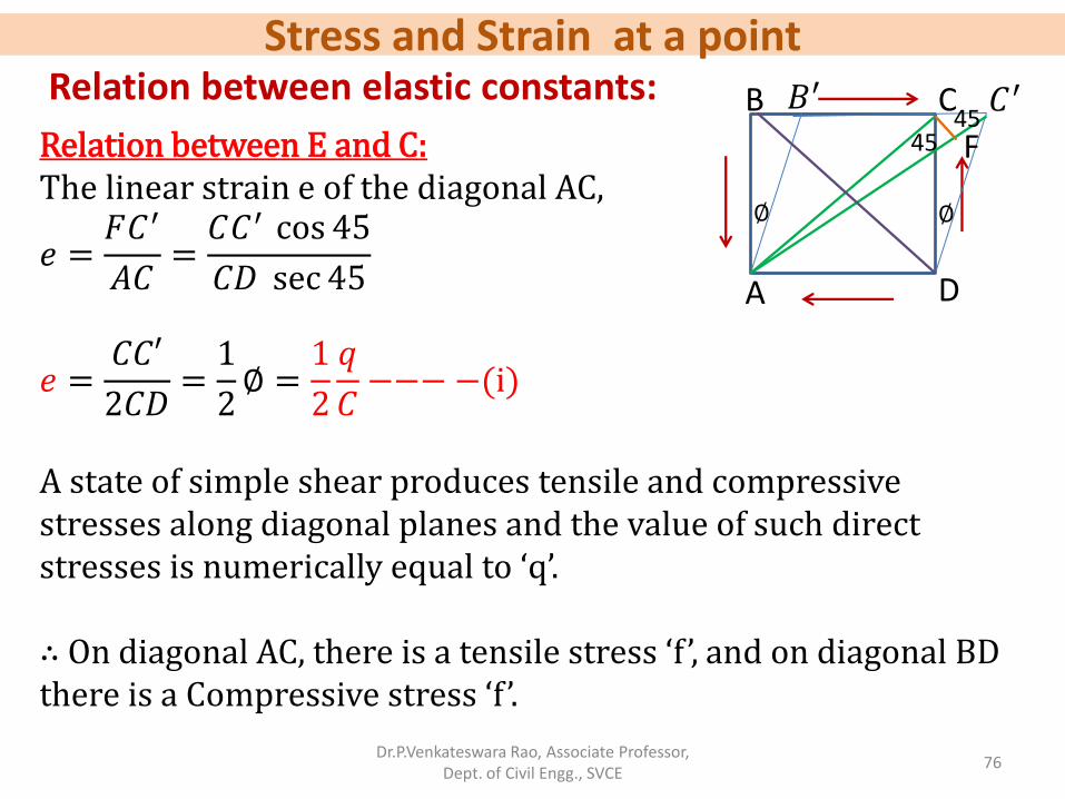
Relation between E and C: The linear strain e of the diagonal AC,
𝑒 =𝐹𝐶′
𝐴𝐶=𝐶𝐶′ cos 45
𝐶𝐷 sec 45
𝑒 =𝐶𝐶′
2𝐶𝐷=1
2∅ =
1
2
𝑞
𝐶−−−−(i)
A state of simple shear produces tensile and compressive stresses along diagonal planes and the value of such direct stresses is numerically equal to ‘q’. ∴ On diagonal AC, there is a tensile stress ‘f ’, and on diagonal BD there is a Compressive stress ‘f ’.
A
B C
D
𝐵′ 𝐶′
F
∅ ∅
45 45
Stress and Strain at a point
Dr.P.Venkateswara Rao, Associate Professor, Dept. of Civil Engg., SVCE
77
Relation between elastic constants:
Relation between E and C (contd…): The linear strain e of the diagonal AC, due to the two mutually perpendicular direct Stresses is given by
𝑒 =𝑓
𝐸− −
𝑓
𝑚𝐸=𝑓
𝐸1 +
1
𝑚
But 𝑓 = 𝑞
𝑒 =𝑞
𝐸1 +
1
𝑚−−−− ii
Equating (i) and (ii), we get 1
2
𝑞
𝐶=𝑞
𝐸1 +
1
𝑚
𝑬 = 𝟐𝑪 𝟏 +𝟏
𝒎
A
B C
D
𝐵′ 𝐶′
F
∅ ∅
45 45
q q
q
q
Stress and Strain at a point
Dr.P.Venkateswara Rao, Associate Professor, Dept. of Civil Engg., SVCE
78
Relation between elastic constants:
Relation between K and C:
𝐸 = 3𝐾 1 −2
𝑚−−−(1)
𝐸 = 2𝐶 1 +1
𝑚−−−(2)
Equating (1) and (2), 𝟏
𝒎=𝟑𝑲 − 𝟐𝑪
𝟔𝑲 + 𝟐𝑪
Relation between E, K and C:
By eliminating 1
𝑚 𝑤𝑒 𝑔𝑒𝑡,
𝑬 =𝟗𝑲𝑪
𝟑𝑲 + 𝑪
A
B C
D
𝐵′ 𝐶′
F
∅ ∅
45 45
q q
q
q
Stress and Strain at a point
Dr.P.Venkateswara Rao, Associate Professor, Dept. of Civil Engg., SVCE
79
Problem:
A solid circular rod of diameter 30 mm and length 2m, when subjected to an axial tensile load, the diameter of the bar is reduced by 0.005 mm. If the young’s modulus of the material of the rod is 200 kN/𝑚𝑚2 and modulus of rigidity is 80 kN/𝑚𝑚2 determine the following: (i) Axial load applied on the bar. (ii) The normal stress induced in the bar. (iii) The change in the length of the bar and (iv) Bulk modulus of the material of the bar.
Stress and Strain at a point
Dr.P.Venkateswara Rao, Associate Professor, Dept. of Civil Engg., SVCE
80
Solution:
A solid circular rod of diameter 30 mm and length 2m, when subjected to an axial tensile load, the diameter of the bar is reduced by 0.005 mm.
P P d= 30 mm L= 2m=2000 mm P=? 𝛿𝑑 = 0.005 𝑚𝑚
If the young’s modulus of the material of the rod is 200 kN/𝑚𝑚2 and modulus of rigidity is 80 kN/𝑚𝑚2
E= 200 kN/𝑚𝑚2
C=80 kN/𝑚𝑚2
𝑓 =?
𝛿L=? K =?
Stress and Strain at a point
Dr.P.Venkateswara Rao, Associate Professor, Dept. of Civil Engg., SVCE
81
Solution:
We know the relation,
P P
𝐸 = 2𝐶 1 +1
𝑚
1 +1
𝑚=𝐸
2𝐶
1
𝑚=𝐸
2𝐶− 1
=2 × 10⁵
2 × 0.8 × 105− 1 = 0.25
∴1
𝑚= 0.25
Stress and Strain at a point
Dr.P.Venkateswara Rao, Associate Professor, Dept. of Civil Engg., SVCE
82
Solution:
We know the relation,
P P
1
𝑚=𝑙𝑎𝑡𝑒𝑟𝑎𝑙 𝑠𝑡𝑟𝑎𝑖𝑛
𝛿𝑑𝑑
𝐿𝑖𝑛𝑒𝑎𝑟 𝑠𝑡𝑟𝑎𝑖𝑛 𝛿𝐿𝐿
0.25 =
0.00530𝛿𝐿2000
𝛿𝐿 = 1.33 𝑚𝑚 (iii) The change in length of the bar=1.33 mm
Stress and Strain at a point
Dr.P.Venkateswara Rao, Associate Professor, Dept. of Civil Engg., SVCE
83
Solution:
P P
Young′s modulus, E =𝐷𝑖𝑟𝑒𝑐𝑡 𝑠𝑡𝑟𝑒𝑠𝑠 (𝑓)
𝐿𝑖𝑛𝑒𝑎𝑟 𝑠𝑡𝑟𝑎𝑖𝑛 𝛿𝐿𝐿
𝑓 = 𝐸𝛿𝐿
𝐿
𝑓 = 2 × 105 ×1.33
2000= 133 N/𝑚𝑚2
(ii)∴ The normal stress induced in the bar, 𝑓 = 133 𝑁/𝑚𝑚2
𝑓 =𝑃
𝐴
𝑃 = 𝑓𝐴 = 133 ×𝜋
4302 = 94012.16 N
(i) ∴ Axial load applied on the bar, 𝑃 = 94.01 𝑘𝑁
Stress and Strain at a point
Dr.P.Venkateswara Rao, Associate Professor, Dept. of Civil Engg., SVCE
Dr.P.Venkateswara Rao, Associate Professor, Dept. of Civil Engg., SVCE
85
Problem 2:
A rod of length 1 m and diameter 20 mm is subjected to a tensile load of 20 kN. The increase in length of the rod is 0.3 mm and decrease in diameter is 0.0018 mm. Calculate poisson’s ratio and three moduli.
Stress and Strain at a point
Dr.P.Venkateswara Rao, Associate Professor, Dept. of Civil Engg., SVCE
86
Solution: d = 20 mm 𝐿 = 1 𝑚 = 1000 𝑚𝑚 𝑃 = 20 𝑘𝑁 = 20 × 103 N 𝛿𝐿 = 0.3 𝑚𝑚 𝛿𝑑 = 0.0018 𝑚𝑚
1
𝑚= 0.3
E = 2.12 × 10⁵ N/𝑚𝑚2
1
𝑚=? , 𝐸 =? , 𝐶 =? , 𝐾 =?
C = 0.82 × 10⁵ N/𝑚𝑚2
K = 1.77 × 10⁵ N/𝑚𝑚2
Stress and Strain at a point
Dr.P.Venkateswara Rao, Associate Professor, Dept. of Civil Engg., SVCE
87
Thin Cylinders
𝜃 𝜃
dP dP
A
B
𝑓1
𝑓1
𝑓1
𝑓1
X X
p
p
p
C D
𝑓2 𝑓2
𝑓2 𝑓2
Y
Y
Fig. shows a thin cylindrical shell whose internal diameter is d, the thickness of the shell being t. Let the length of the shell be L. Let the shell be subjected to an internal pressure of P.
Stress and Strain at a point
Dr.P.Venkateswara Rao, Associate Professor, Dept. of Civil Engg., SVCE
88
Thin Cylinders (contd…)
𝜃 𝜃
𝑑𝑃𝑛 𝑑𝑃𝑛
A
B
𝑓1
𝑓1
𝑓1
𝑓1
X X
Let us consider a longitudinal section XX through the axis , dividing the shell into two halves A and B. Now let us consider two elementary strips subtending an angle d𝜃 at the centre at an angle 𝜃 on either side of the vertical through the centre. Normal force on each strip 𝑑𝑃𝑛 = 𝑝 𝑟 𝑑𝜃 𝐿 Where r is the radius of the shell.
Stress and Strain at a point
Dr.P.Venkateswara Rao, Associate Professor, Dept. of Civil Engg., SVCE
89
Thin Cylinders (contd…)
𝜃 𝜃
dP dP
A
B
𝑓1
𝑓1
𝑓1
𝑓1
X X
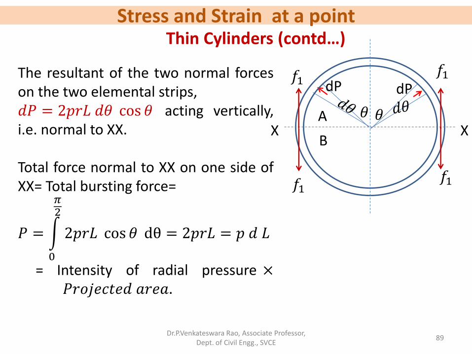
The resultant of the two normal forces on the two elemental strips, 𝑑𝑃 = 2𝑝𝑟𝐿 𝑑𝜃 cos 𝜃 acting vertically, i.e. normal to XX. Total force normal to XX on one side of XX= Total bursting force=
𝑃 = 2𝑝𝑟𝐿 cos 𝜃
𝜋2
0
dθ = 2𝑝𝑟𝐿 = 𝑝 𝑑 𝐿
= Intensity of radial pressure × 𝑃𝑟𝑜𝑗𝑒𝑐𝑡𝑒𝑑 𝑎𝑟𝑒𝑎.
Stress and Strain at a point
Dr.P.Venkateswara Rao, Associate Professor, Dept. of Civil Engg., SVCE
90
Thin Cylinders (contd…)
𝜃 𝜃
dP dP
A
B
𝑓1
𝑓1
𝑓1
𝑓1
X X
Let 𝑓1be the intensity of tensile stress induced in the metal across the section XX. Resisting force offered by the section XX=𝑓1 × 2𝑡𝐿 Equating the resisting force to the bursting force
𝑓1 × 2𝑡𝐿 = 𝑝𝑑 𝐿
∴ 𝒇𝟏 =𝒑 𝒅
𝟐 𝒕
Stress and Strain at a point
Dr.P.Venkateswara Rao, Associate Professor, Dept. of Civil Engg., SVCE
91
Thin Cylinders (contd…)
𝜃 𝜃
dP dP
A
B
𝑓1
𝑓1
𝑓1
𝑓1
X X
Just like the section XX, if we had considered any other longitudinal section, the intensity of tensile stress would be found to be the same. Hence the direction of the tensile stress is along the circumference of the shell. A stress so induced is called a hoop or circumferential stress.
Stress and Strain at a point
Dr.P.Venkateswara Rao, Associate Professor, Dept. of Civil Engg., SVCE
92
Thin Cylinders (contd…)
Let us now consider a section YY normal to the axis of the shell. Let the section divide the shell into two parts C and D. Force acting on the end of the shell=
𝑃 = 𝑝 ×𝜋
4𝑑2
In order the shell may not be split up at the section YY, the section will offer a resistance.
P
P
P
C D
𝑓2 𝑓2
𝑓2 𝑓2
Y
Y
Stress and Strain at a point
Dr.P.Venkateswara Rao, Associate Professor, Dept. of Civil Engg., SVCE
93
Thin Cylinders (contd…)
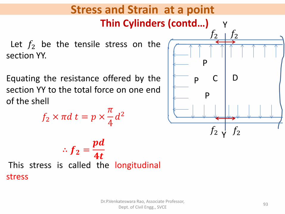
Let 𝑓2 be the tensile stress on the section YY. Equating the resistance offered by the section YY to the total force on one end of the shell
𝑓2 × 𝜋𝑑 𝑡 = 𝑝 ×𝜋
4𝑑2
∴ 𝒇𝟐 =𝒑𝒅
𝟒𝒕
This stress is called the longitudinal stress
P
P
P
C D
𝑓2 𝑓2
𝑓2 𝑓2
Y
Y
Stress and Strain at a point
Dr.P.Venkateswara Rao, Associate Professor, Dept. of Civil Engg., SVCE
94
Thin Cylinders (contd…)
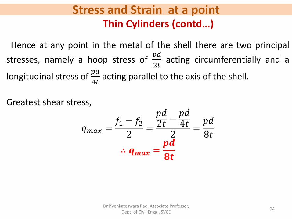
Hence at any point in the metal of the shell there are two principal
stresses, namely a hoop stress of 𝑝𝑑
2𝑡 acting circumferentially and a
longitudinal stress of 𝑝𝑑
4𝑡 acting parallel to the axis of the shell.
Greatest shear stress,
𝑞𝑚𝑎𝑥 =𝑓1 − 𝑓22
=
𝑝𝑑2𝑡 −
𝑝𝑑4𝑡
2=𝑝𝑑
8𝑡
∴ 𝒒𝒎𝒂𝒙 =𝒑𝒅
𝟖𝒕
Stress and Strain at a point
Dr.P.Venkateswara Rao, Associate Professor, Dept. of Civil Engg., SVCE
95
Thin Cylinders (contd…)
Circumferential strain,
𝑒1 =𝑓1𝐸−𝑓2𝑚𝐸
=𝑝𝑑
2𝑡𝐸−𝑝𝑑
4𝑡𝑚𝐸
=𝑝𝑑
2𝑡𝐸1 −
1
2𝑚
∴ 𝑒1 =𝑝𝑑
4𝑡𝐸2 −
1
𝑚
Stress and Strain at a point
Dr.P.Venkateswara Rao, Associate Professor, Dept. of Civil Engg., SVCE
96
Thin Cylinders (contd…)
Longitudinal strain,
𝑒2 =𝑓2𝐸−𝑓1𝑚𝐸
=𝑝𝑑
4𝑡𝐸−𝑝𝑑
2𝑡𝑚𝐸
∴ 𝑒2 =𝑝𝑑
2𝑡𝐸
1
2−1
𝑚
Circumferential strain =𝐶ℎ𝑎𝑛𝑔𝑒 𝑖𝑛 𝑐𝑖𝑟𝑐𝑢𝑚𝑓𝑒𝑟𝑒𝑛𝑐𝑒
𝑜𝑟𝑖𝑔𝑖𝑛𝑎𝑙 𝑐𝑖𝑟𝑐𝑢𝑚𝑓𝑒𝑟𝑒𝑛𝑐𝑒=𝜋𝛿𝑑
𝜋𝑑=𝑒1
𝛿𝑑
𝑑= 𝑒1
Similarly, Longitudinal strain 𝛿𝐿
𝐿= 𝑒2
Stress and Strain at a point
Dr.P.Venkateswara Rao, Associate Professor, Dept. of Civil Engg., SVCE
97
Thin Cylinders (contd…) Volume of the cylinder,
𝑉 = 𝜋
4𝑑2L
Change in volume,
𝛿𝑉 =𝜋
4𝑑2 δ𝐿 +
𝜋
42d δ𝑑 𝐿
Volumetric strain,
𝛿𝑉
𝑉=
𝜋4𝑑2 δ𝐿 +
𝜋42d δ𝑑 𝐿
𝜋4𝑑2L
=𝛿𝐿
𝐿+ 2
𝛿𝑑
𝑑
∴ 𝒆𝒗 = 𝒆𝟐 + 𝟐𝒆𝟏 𝛿𝑉
𝑉=𝑝𝑑
2𝑡𝐸
1
2−1
𝑚+2𝑝𝑑
2𝑡𝐸1 −
1
2𝑚
𝛿𝑉
𝑉=𝑝𝑑
2𝑡𝐸
5
2−2
𝑚
Stress and Strain at a point
Dr.P.Venkateswara Rao, Associate Professor, Dept. of Civil Engg., SVCE
98
Thin Cylinders (contd…) 𝜹𝑽
𝑽=𝒑𝒅
𝟐𝒕𝑬
𝟓
𝟐−𝟐
𝒎
𝜹𝑽 =𝒑𝒅
𝟒𝒕𝑬𝟓 −
𝟒
𝒎× 𝑽
Stress and Strain at a point
Dr.P.Venkateswara Rao, Associate Professor, Dept. of Civil Engg., SVCE
99
Problem: A thin cylindrical shell 3.5 m long, 1.5 m in diameter and 15 mm thick is subjected to a pressure of 1.5 Mpa. Calculate the maximum shear stress and change in dimensions of the shell. E= 2× 10⁵ N/𝑚𝑚2 and poisson’s ratio is 0.3 also calculate change in volume.
Stress and Strain at a point
Dr.P.Venkateswara Rao, Associate Professor, Dept. of Civil Engg., SVCE
100
Solution: A thin cylindrical shell 3.5 m long, 1.5 m in diameter and 15 mm thick is subjected to a pressure of 1.5 MPa. Calculate the maximum shear stress and change in dimensions of the shell. E= 2× 10⁵ N/𝑚𝑚2 and poisson’s ratio is 0.3 also calculate change in volume. L=3.5 m=3500 mm, d=1.5 m=1500 mm, t=15 mm, p=1.5 MPa.
E=2 × 10⁵ N/𝑚𝑚2, 1
𝑚= 0.3.
𝑞𝑚𝑎𝑥 =? , δ𝐿 =? , 𝛿𝑑 =?
𝛿𝑉 =?
Stress and Strain at a point
Dr.P.Venkateswara Rao, Associate Professor, Dept. of Civil Engg., SVCE
101
Solution (contd…): Circumferential stress,
𝑓1 =𝑝𝑑
2𝑡=1.5 × 1500
2 × 15= 75 N/𝑚𝑚2
Longitudinal stress,
𝑓2 =𝑝𝑑
4𝑡=1.5 × 1500
4 × 15= 37.5 N/𝑚𝑚2
Maximum shear stress,
𝒒𝒎𝒂𝒙 =𝒇𝟏 − 𝒇𝟐𝟐
=𝟕𝟓 − 𝟑𝟕. 𝟓
𝟐= 𝟏𝟖. 𝟕𝟓 𝐍/𝒎𝒎𝟐
Stress and Strain at a point
Dr.P.Venkateswara Rao, Associate Professor, Dept. of Civil Engg., SVCE
102
Solution (contd…):
Circumferential strain,
𝑒1 =𝑓1𝐸−𝑓2𝑚𝐸
=75
2 × 10⁵− 0.3 ×
37.5
2 × 105= 31.875 × 10⁻⁵
Longitudinal strain,
𝑒2 =𝑓2𝐸−𝑓1𝑚𝐸
=37.5
2 × 10⁵− 0.3 ×
75
2 × 105= 7.5 × 10⁻⁵
Change in diameter,
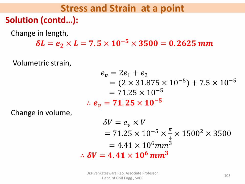
𝛿𝑑 = 𝑒1 × 𝑑 = 31.875 × 10−5 × 1500 = 0.478 𝑚𝑚
∴ 𝜹𝒅 = 𝟎. 𝟒𝟕𝟖 𝒎𝒎
Stress and Strain at a point
Dr.P.Venkateswara Rao, Associate Professor, Dept. of Civil Engg., SVCE
Dr.P.Venkateswara Rao, Associate Professor, Dept. of Civil Engg., SVCE
104
Problem: A built up cylindrical shell of 300 mm diameter and 3 m long and 6 mm thick is subjected to an internal pressure of 2 MPa. Calculate the change in diameter, change in length and change in volume of cylinder. Efficiency of longitudinal joint is 80% and that of circumferential joint is 50%. Assume E= 200 GPa and poisson’s ratio is 0.29.
Stress and Strain at a point
Dr.P.Venkateswara Rao, Associate Professor, Dept. of Civil Engg., SVCE
105
Problem: A built up cylindrical shell of 300 mm diameter and 3 m long and 6 mm thick is subjected to an internal pressure of 2 MPa. Calculate the change in diameter, change in length and change in volume of cylinder. Efficiency of longitudinal joint is 80% and that of circumferential joint is 50%. Assume E= 200 GPa and poisson’s ratio is 0.29. d=300 mm, L=3 m=3000 mm, t=6 mm, p=2 Mpa
𝛿𝑑 =? , 𝛿𝐿 =? , 𝛿𝑉 =?
η𝐿 = 80% = 0.8, η𝑐 = 50% = 0.5, 𝐸 = 200 𝐺𝑃𝑎, 1
𝑚= 0.29
Stress and Strain at a point
Dr.P.Venkateswara Rao, Associate Professor, Dept. of Civil Engg., SVCE
106
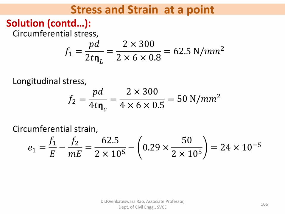
Solution (contd…): Circumferential stress,
𝑓1 =𝑝𝑑
2𝑡η𝐿=
2 × 300
2 × 6 × 0.8= 62.5 N/𝑚𝑚2
Longitudinal stress,
𝑓2 =𝑝𝑑
4𝑡η𝑐=
2 × 300
4 × 6 × 0.5= 50 N/𝑚𝑚2
Circumferential strain,
𝑒1 =𝑓1𝐸−𝑓2𝑚𝐸
=62.5
2 × 10⁵− 0.29 ×
50
2 × 105= 24 × 10−5
Stress and Strain at a point
Dr.P.Venkateswara Rao, Associate Professor, Dept. of Civil Engg., SVCE
107
Solution (contd…):
Longitudinal strain,
𝑒2 =𝑓2𝐸−𝑓1𝑚𝐸
=50
2 × 10⁵− 0.29 ×
62.5
2 × 105= 15.94 × 10⁻⁵
Change in diameter,
𝛿𝑑 = 𝑒1 × 𝑑 = 24 × 10−5 × 300 = 0.072 𝑚𝑚
∴ 𝜹𝒅 = 𝟎. 𝟎𝟕𝟐 𝒎𝒎
Change in length,
𝜹𝑳 = 𝒆𝟐 × 𝑳 = 𝟏𝟓. 𝟗𝟒 × 𝟏𝟎−𝟓 × 𝟑𝟎𝟎𝟎 = 𝟎. 𝟒𝟕𝟖𝟐 𝒎𝒎
Stress and Strain at a point
Dr.P.Venkateswara Rao, Associate Professor, Dept. of Civil Engg., SVCE
• When a member is deformed under the action of external loading, the member is said to have stored energy which is called the ‘strain energy’ or the ‘resilience’ of the member.
• The strain energy stored by the member is equal to the amount of work done by the external forces to produce deformation.
Dr.P.Venkateswara Rao, Associate Professor, Dept. of Civil Engg., SVCE
109
Strain energy due to axial force • A member subjected to an external load W.
• Let the extension of the member be ‘δ’.
• Since the load is applied gradually, the magnitude
of the load is increased gradually from zero to the
value ‘W’ and the member also has gradually
extended.
• External work done, 𝑊𝑒= Avg.load × displacement
= 0+𝑊
2 × δ =
1
2 Wδ.
• Let the energy stored by the member be 𝑊𝑖.
• We have 𝑊𝑒=𝑊𝑖,
• Let the tension in the member be ‘S’.
• For the equilibrium of the member, S = W.
w
w
δ
A
Stress and Strain at a point
• Tensile stress, 𝑓 =𝑆
𝐴 ,
• Tensile strain, e = 𝑓
𝐸=𝑆
𝐴𝐸,
• Where E is the young’s modulus of the material.
• Change in length, δ= e× 𝑙 = 𝑆𝑙
𝐴𝐸
• Strain energy stored = work done = 1
2 Wδ
• Strain energy stored per unit volume = 𝑠2𝑙
2𝐴𝐸 ÷ 𝐴𝑙 =
𝑓2
2𝐸
Strain energy due to axial force (contd…)
𝑈𝐴=1
2× 𝑆 ×
𝑆𝑙
𝐴𝐸= 𝑠2𝑙
2𝐴𝐸
∴ 𝑈𝐴= 𝑠2𝑙
2𝐴𝐸
w
w
δ
A
Stress and Strain at a point
Stress and Strain at a point • Stresses due to various types of loads:
• (i) Gradually applied load:
Let a load of magnitude ‘W’ be applied axially on a member of length ‘L’ and uniform cross sectional area A.
Let 𝛿𝐿 be the extension of the rod.
Let ‘f’ be the stress intensity in the rod.
Strain energy stored by the member,
𝑈 =𝑓2
2𝐸× 𝑉𝑜𝑙𝑢𝑚𝑒 𝑜𝑓 𝑡ℎ𝑒 𝑟𝑜𝑑
=𝑓2
2𝐸× 𝐴𝐿
Work done by the external load= Average load × extension
=1
2W 𝛿𝐿
Dr.P.Venkateswara Rao, Associate Professor, Dept. of Civil Engg., SVCE
112
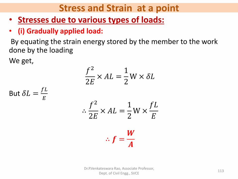
Stress and Strain at a point • Stresses due to various types of loads: • (i) Gradually applied load:
By equating the strain energy stored by the member to the work done by the loading
We get, 𝑓2
2𝐸× 𝐴𝐿 =
1
2W × 𝛿𝐿
But 𝛿𝐿 =𝑓𝐿
𝐸
∴𝑓2
2𝐸× 𝐴𝐿 =
1
2W ×
𝑓𝐿
𝐸
∴ 𝒇 =𝑾
𝑨
Dr.P.Venkateswara Rao, Associate Professor, Dept. of Civil Engg., SVCE
113
Stress and Strain at a point • Stresses due to various types of loads: (ii) Suddenly applied load: Let the load ‘W’ be suddenly applied. Let the extension of the member be 𝛿𝐿. In this case the magnitude of load is constant as ‘W’ throughout the process of extension. Let ‘f’ be the maximum stress induced. Equating the strain energy stored by the member to the work done by the loading,
𝑓2
2𝐸× 𝐴𝐿 = W× 𝛿𝐿
But 𝛿𝐿 =𝑓𝐿
𝐸
∴𝑓2
2𝐸× 𝐴𝐿 = W×
𝑓𝐿
𝐸
∴ 𝒇 =𝟐𝑾
𝑨
Dr.P.Venkateswara Rao, Associate Professor, Dept. of Civil Engg., SVCE
114
Stress and Strain at a point • Stresses due to various types of loads:
(iii) Impact load:
In this case the load ‘W’ is dropped from a height ‘h’ before it commences to stretch the bar.
Fig. shows a vertical bar when upper end is fixed at top and a collar is provided at the lower end.
The load ‘W’ drops by a height ‘h’ on the collar and will thus extend the member by ‘𝛿𝐿′.
Let ‘f’ be the maximum intensity of stress produced in the bar.
Dr.P.Venkateswara Rao, Associate Professor, Dept. of Civil Engg., SVCE
115
L
h
𝛿𝐿
Stress and Strain at a point • Stresses due to various types of loads:
(iii) Impact load (contd…):
Extension of the bar,
𝛿𝐿 =𝑓𝐿
𝐸
Equating the bar potential energy to the strain energy by the rod
𝑊 ℎ + 𝛿𝐿 =𝑓2
2𝐸× 𝐴𝐿
𝑊 ℎ +𝑓𝐿
𝐸=𝑓2
2𝐸× 𝐴𝐿
𝑓2
2𝐸× 𝐴𝐿 −
𝑓𝑊𝐿
𝐸= Wh
Dr.P.Venkateswara Rao, Associate Professor, Dept. of Civil Engg., SVCE
116
Stress and Strain at a point • Stresses due to various types of loads:
• (iii) Impact load (contd…):
𝑓2 −2𝑊𝑓
𝐴=2𝑊ℎ𝐸
𝐴𝐿
Adding 𝑊2
𝐴2 to both sides of this equation, we get
𝑓2 −2𝑊
𝐴𝑓 +
𝑊2
𝐴2 =𝑊2
𝐴2+2𝑊ℎ𝐸
𝐴𝐿
𝑓 −𝑊
𝐴
2
=𝑊2
𝐴2+2𝑊ℎ𝐸
𝐴𝐿
Dr.P.Venkateswara Rao, Associate Professor, Dept. of Civil Engg., SVCE
117
Stress and Strain at a point • Stresses due to various types of loads: • (iii) Impact load (contd…):
𝑓 −𝑊
𝐴
2
=𝑊2
𝐴2+2𝑊ℎ𝐸
𝐴𝐿
𝑓 −𝑊
𝐴=
𝑊2
𝐴2+2𝑊ℎ𝐸
𝐴𝐿
𝑓 =𝑊
𝐴+
𝑊2
𝐴2+ 2𝐸
𝑊
𝐴
ℎ
𝐿
∴ 𝒇 =𝑾
𝑨𝟏 + 𝟏 + 𝟐𝑬
𝑨
𝑾
𝒉
𝑳
Dr.P.Venkateswara Rao, Associate Professor, Dept. of Civil Engg., SVCE
118
Stress and Strain at a point • Problem:
A bar 12 mm diameter gets stretched by 2 mm under a gradually applied load of 10 kN. What stress would be produced in the same bar by a weight of 12 kN which falls vertically a distance of 4 cm on to a rigid collar attached at its end. The bar is initially unstressed. E= 200 GPa.
Dr.P.Venkateswara Rao, Associate Professor, Dept. of Civil Engg., SVCE
119
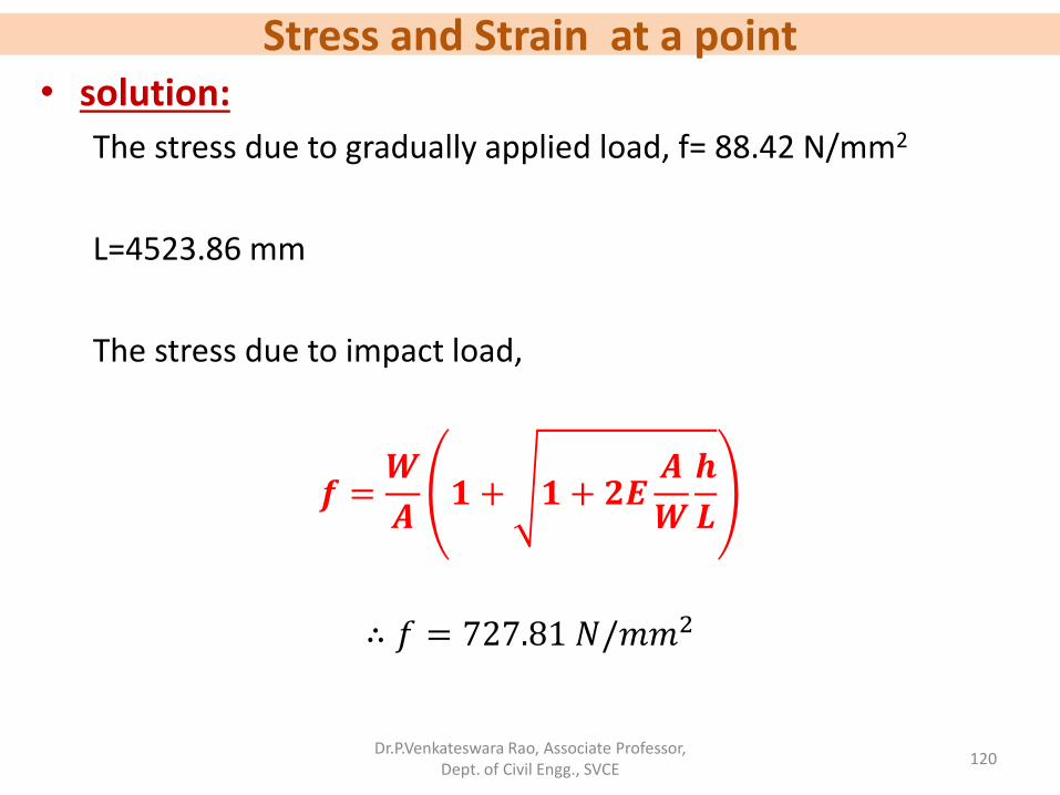
Stress and Strain at a point • solution:
The stress due to gradually applied load, f= 88.42 N/mm2
L=4523.86 mm
The stress due to impact load,
𝒇 =𝑾
𝑨𝟏 + 𝟏 + 𝟐𝑬
𝑨
𝑾
𝒉
𝑳
∴ 𝑓 = 727.81 𝑁/𝑚𝑚2
Dr.P.Venkateswara Rao, Associate Professor, Dept. of Civil Engg., SVCE
120
Stress and Strain at a point • Problem:
An unknown weight falls through 10 mm on to a collar rigidly attached to the lower end of a vertical bar 3m long and 600 mm2 in section. If the maximum instantaneous extension is 2 mm, what is the corresponding stress and the value of unknown weight. E= 2× 10⁵ MPa.
Dr.P.Venkateswara Rao, Associate Professor, Dept. of Civil Engg., SVCE
121
Stress and Strain at a point • Solution:
𝑓 = 133.33 𝑁/𝑚𝑚2
𝑊 = 6666.67 𝑁
Dr.P.Venkateswara Rao, Associate Professor, Dept. of Civil Engg., SVCE