UNIT II PROGRAMMING FOR EMBEDDED SYSTEMS The advantages of C C is one of a la rge nu mber of hi gh -l evel la ng ua ges de sign ed fo r general-purpose programming, in ot her words, for wr iti ng anyt hi ng fr om small pr ograms for personal amusement to complex industrial applications. C has many advantages: • Before C, machine-language programmers criticized high-level languages because, with their black box approach, they shielded the user from the working details of the computer and all its facilities. C, however, was designed to give access to any level ofthe computer down to raw machine language, and because of this, it is perhaps the most flexible high-level language. • C has features that allow the programmer to organize programs in a clear, easy, logical way. For example, C allows meaningful names for variables without any loss ofeffici ency , yet it gives a compl ete freedom of prog rammin g style , includ ing flexible ways of making decisions, and a set of flexible commands for performing tasks repetitively (for, while, do). • C is succinct. It permits the creation of tidy, compact programs. This feature can be a mi xed blessi ng, however , and the C pr ogrammer must balance si mplic it y and readability. • C allows commands that are invalid in other languages. This is no defect, but a powerful freedom which, when used with caution, makes many things possible. It does mean that there are concealed difficulties in C, but if you write carefully and thoughtfully , you can cre ate fast, efficient programs. • With C, you can use every resource your computer offers. C tries to link closely with the local environment, providing facilities for gaining access to common peripherals li ke di sk dr ives and pr inter s. When new peri phera ls are inve nt ed, the GNU community quickly provides the ability to program them in C as well. In fact, most ofthe GNU project is written in C (as are many other operating systems). DATA TYPES : Like most programming languages, C is able to use and process named variables and theircontents. Variables are simply names used to refer to some location in memory – a location that holds a value with which we are working. It may help to think of variab les as a placeholde r for a value. Y ou can think of a variable as being equivalent to its assigned value. So, if you have a variable i that is initialized (set equal) to 4, then it follows that i+1 will equal 5. Since C is a relatively low-level programming language, before a C program can utilize memory to store a variable it must claim the memory needed to store the values for a variable. This is done by declaring variables. Declaring variables is the way in which a C program shows the number of variables it needs, what they are going to be named, and how much memory they will need.
The second way, which should not be used when you are coding letter characters, is to write
char letter2 = 97; /* in ASCII, 97 = 'a' */
This is considered by some to be extremely bad practice, if we are using it to store a
character, not a small number, in that if someone reads your code, most readers are forced tolook up what character corresponds with the number 97 in the encoding scheme. In the
end, letter1 and letter2 store both the same thing – the letter "a", but the first method is
clearer, easier to debug, and much more straightforward.
One important thing to mention is that characters for numerals are represented differently
from their corresponding number, i.e. '1' is not equal to 1.
There is one more kind of literal that needs to be explained in connection with chars:
the string literal. A string is a series of characters, usually intended to be displayed. They are
surrounded by double quotations (" ", not ' '). An example of a string literal is the "Hello,
world!\n" in the "Hello, World" example.
The float type
float is short for floating point. It stores real numbers also, but is only one machine word in
size. Therefore, it is used when less precision than a double provides is required. floatliterals
must be suffixed with F or f, otherwise they will be interpreted as doubles. Examples are:
3.1415926f, 4.0f, 6.022e+23f. float variables can be declared using the float keyword.
The double type
The double and float types are very similar. The float type allows you to store single-
precision floating point numbers, while the double keyword allows you to store double-
precision floating point numbers – real numbers, in other words, both integer and non-integer
values. Its size is typically two machine words, or 8 bytes on most machines. Examples
of double literals are 3.1415926535897932, 4.0, 6.022e+23 (scientific notation). If you use 4
instead of 4.0, the 4 will be interpreted as an int.
The distinction between floats and doubles was made because of the differing sizes of the two
types. When C was first used, space was at a minimum and so the judicious use of a float
instead of a double saved some memory. Nowadays, with memory more freely available, you
do not really need to conserve memory like this – it may be better to use doubles consistently.
Indeed, some C implementations use doubles instead of floats when you declare a float
variable.
If you want to use a double variable, use the double keyword.
Data type modifiers
One can alter the data storage of any data type by preceding it with certain modifiers.
You will see further instances of the #define directive later in the text. It is good convention
to write #defined words in all capitals, so a programmer will know that this is not a variable
that you have declared but a #defined macro.
Bit Manipulation
In C and C++, values are represented as binary values. The exact values will vary from
computer to computer, but the most common sizes at the time of this writing are 127 for char,
32767 for short, and 2147483647 for int and long. The unsigned values are 255, 65535, and
4294967295 respectively. Now, these values are confusing to many programmers, much less
non-programmers. They are obviously one less than powers of two, but when seen in source
code they appear to be magic numbers. An easier way to represent these values is with the
hexadecimal numbering system which shows the binary structure more clearly than decimal
values. In hexadecimal, each digit corresponds to four bits of the binary value, with valuesfrom 10 to 15 being represented by the letters A through F. So the values 0x7F and 0xFF are
the hexadecimal equivalent to the decimal values for char shown above, signed and unsigned
respectively.
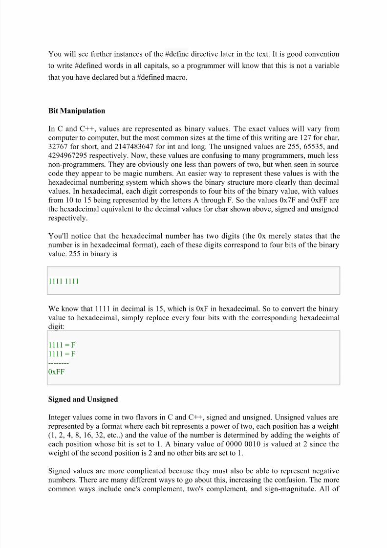
You'll notice that the hexadecimal number has two digits (the 0x merely states that the
number is in hexadecimal format), each of these digits correspond to four bits of the binary
value. 255 in binary is
1111 1111
We know that 1111 in decimal is 15, which is 0xF in hexadecimal. So to convert the binary
value to hexadecimal, simply replace every four bits with the corresponding hexadecimal
digit:
1111 = F
1111 = F
--------
0xFF
Signed and Unsigned
Integer values come in two flavors in C and C++, signed and unsigned. Unsigned values are
represented by a format where each bit represents a power of two, each position has a weight
(1, 2, 4, 8, 16, 32, etc..) and the value of the number is determined by adding the weights of
each position whose bit is set to 1. A binary value of 0000 0010 is valued at 2 since the
weight of the second position is 2 and no other bits are set to 1.
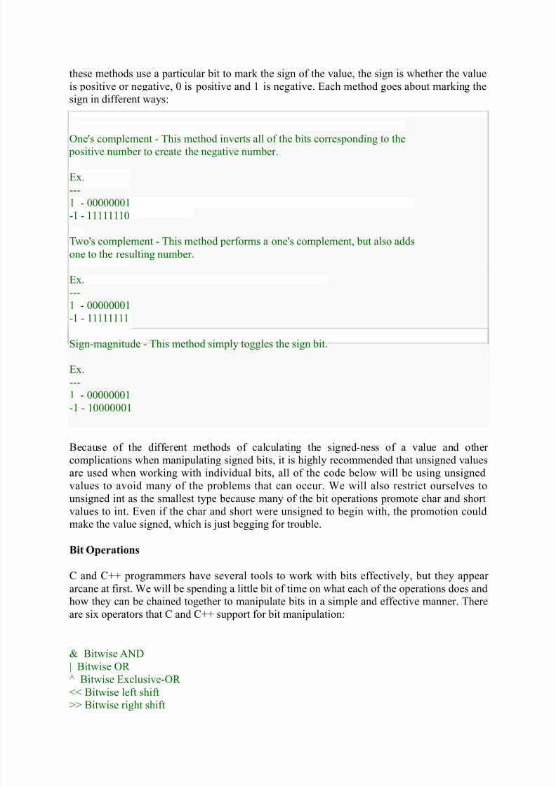
Signed values are more complicated because they must also be able to represent negative
numbers. There are many different ways to go about this, increasing the confusion. The morecommon ways include one's complement, two's complement, and sign-magnitude. All of
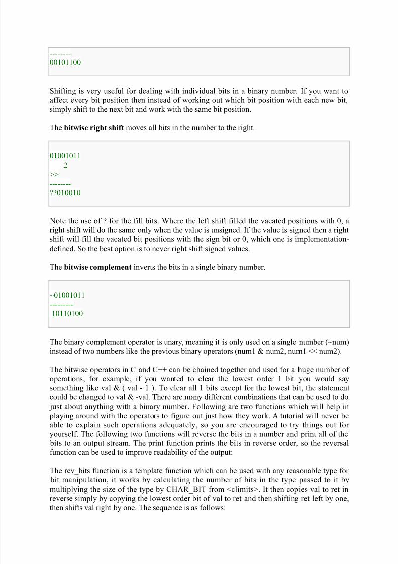
Shifting is very useful for dealing with individual bits in a binary number. If you want to
affect every bit position then instead of working out which bit position with each new bit,simply shift to the next bit and work with the same bit position.
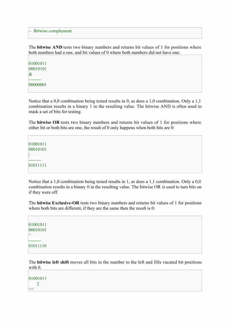
The bitwise right shift moves all bits in the number to the right.
01001011
2
>>
--------
??010010
Note the use of ? for the fill bits. Where the left shift filled the vacated positions with 0, a
right shift will do the same only when the value is unsigned. If the value is signed then a right
shift will fill the vacated bit positions with the sign bit or 0, which one is implementation-
defined. So the best option is to never right shift signed values.
The bitwise complement inverts the bits in a single binary number.
~01001011---------
10110100
The binary complement operator is unary, meaning it is only used on a single number (~num)
instead of two numbers like the previous binary operators (num1 & num2, num1 << num2).
The bitwise operators in C and C++ can be chained together and used for a huge number of
operations, for example, if you wanted to clear the lowest order 1 bit you would say
something like val & ( val - 1 ). To clear all 1 bits except for the lowest bit, the statement
could be changed to val & -val. There are many different combinations that can be used to do just about anything with a binary number. Following are two functions which will help in
playing around with the operators to figure out just how they work. A tutorial will never be
able to explain such operations adequately, so you are encouraged to try things out for
yourself. The following two functions will reverse the bits in a number and print all of the
bits to an output stream. The print function prints the bits in reverse order, so the reversal
function can be used to improve readability of the output:
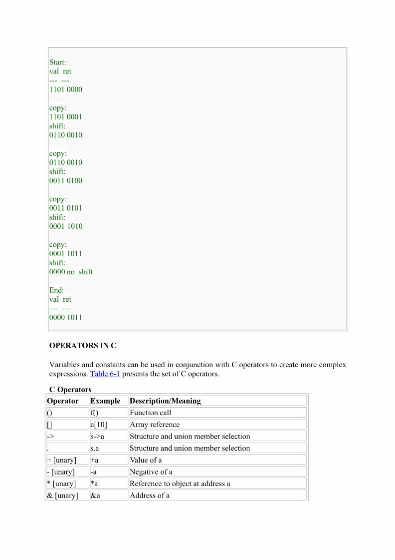
The rev_bits function is a template function which can be used with any reasonable type for
bit manipulation, it works by calculating the number of bits in the type passed to it by
multiplying the size of the type by CHAR_BIT from <climits>. It then copies val to ret in
reverse simply by copying the lowest order bit of val to ret and then shifting ret left by one,
then shifts val right by one. The sequence is as follows:
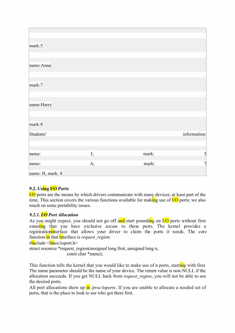
When you are done with a set of I/O ports (at module unload time, perhaps), they should be
returned to the system with:
void release_region(unsigned long start, unsigned long n);
There is also a function that allows your driver to check to see whether a given set
of I/O ports is available:int check_region(unsigned long first, unsigned long n);
Here, the return value is a negative error code if the given ports are not available. This
function is deprecated because its return value provides no guarantee of whether an allocation
would succeed; checking and later allocating are not an atomic operation. We list it here
because several drivers are still using it, but you should always use request_region, which
performs the required locking to ensure that the allocation is done in a safe, atomic manner.
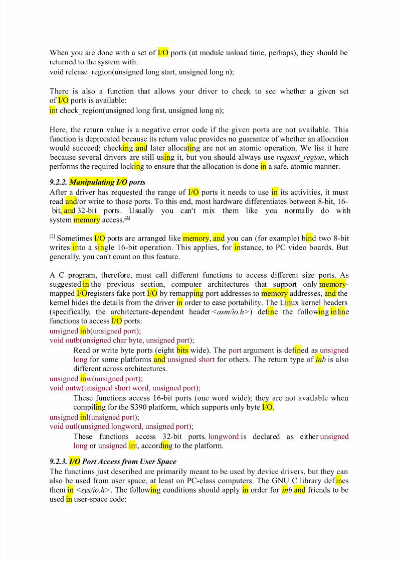
9.2.2. Manipulating I/O ports
After a driver has requested the range of I/O ports it needs to use in its activities, it must
read and/or write to those ports. To this end, most hardware differentiates between 8-bit, 16-
bit, and 32-bit ports. Usually you can't mix them like you normally do with
system memory access.[2]
[2] Sometimes I/O ports are arranged like memory, and you can (for example) bind two 8-bit
writes into a single 16-bit operation. This applies, for instance, to PC video boards. But
generally, you can't count on this feature.
A C program, therefore, must call different functions to access different size ports. As
suggested in the previous section, computer architectures that support only memory-
mapped I/Oregisters fake port I/O by remapping port addresses to memory addresses, and thekernel hides the details from the driver in order to ease portability. The Linux kernel headers
(specifically, the architecture-dependent header <asm/io.h>) def ine the following inline
functions to access I/O ports:
unsigned inb(unsigned port);
void outb(unsigned char byte, unsigned port);
Read or write byte ports (eight bits wide). The port argument is def ined as unsigned
long for some platforms and unsigned short for others. The return type of inb is also
different across architectures.
unsigned inw(unsigned port);
void outw(unsigned short word, unsigned port);
These functions access 16-bit ports (one word wide); they are not available when
compiling for the S390 platform, which supports only byte I/O.
unsigned inl(unsigned port);
void outl(unsigned longword, unsigned port);
These functions access 32-bit ports. longword is declared as either unsigned
long or unsigned int, according to the platform.
9.2.3. I/O Port Access from User Space
The functions just described are primarily meant to be used by device drivers, but they can
also be used from user space, at least on PC-class computers. The GNU C library def ines
them in <sys/io.h>. The following conditions should apply in order for inb and friends to beused in user-space code:
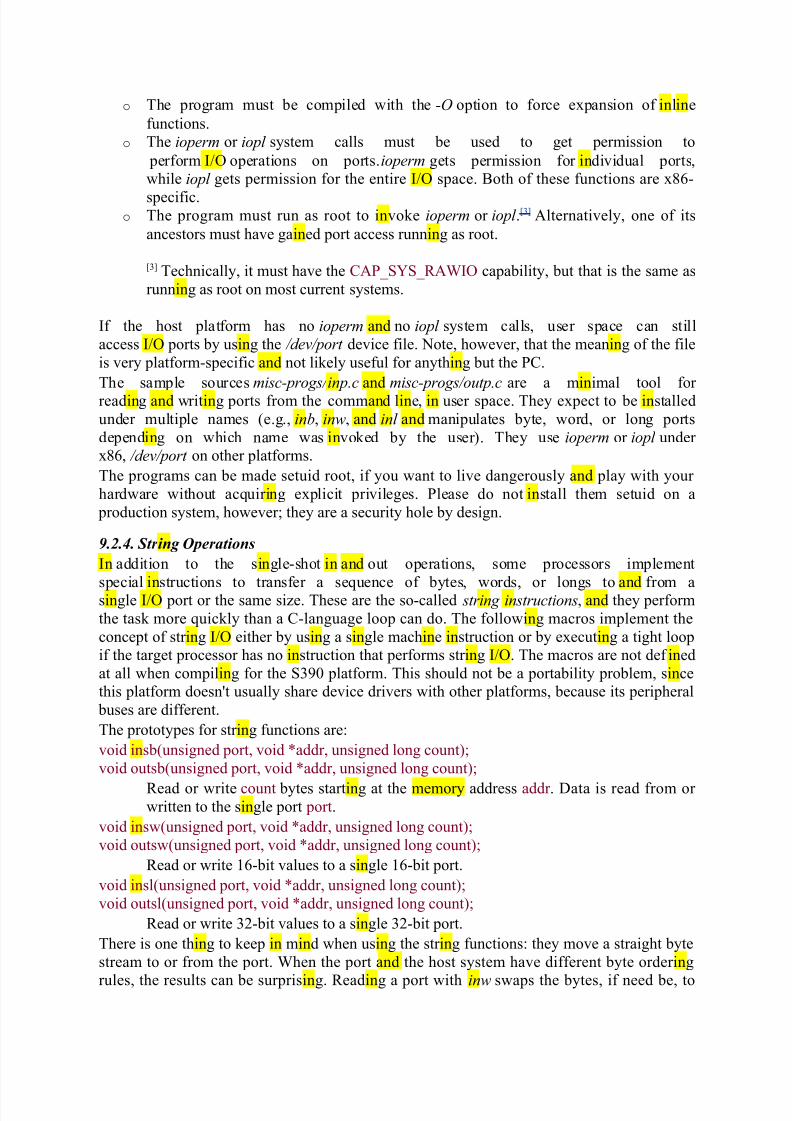
o The program must be compiled with the -O option to force expansion of inline
functions.
o The ioperm or iopl system calls must be used to get permission to
perform I/O operations on ports.ioperm gets permission for individual ports,
while iopl gets permission for the entire I/O space. Both of these functions are x86-
specific.o The program must run as root to invoke ioperm or iopl .[3] Alternatively, one of its
ancestors must have gained port access running as root.
[3] Technically, it must have the CAP_SYS_RAWIO capability, but that is the same as
running as root on most current systems.
If the host platform has no ioperm and no iopl system calls, user space can still
access I/O ports by using the /dev/port device file. Note, however, that the meaning of the file
is very platform-specific and not likely useful for anything but the PC.
The sample sources misc-progs/ inp.c and misc-progs/outp.c are a minimal tool for
reading and writing ports from the command line, in user space. They expect to be installed
under multiple names (e.g., inb, inw, and inl and manipulates byte, word, or long ports
depending on which name was invoked by the user). They use ioperm or iopl under
x86, /dev/port on other platforms.
The programs can be made setuid root, if you want to live dangerously and play with your
hardware without acquiring explicit privileges. Please do not install them setuid on a
production system, however; they are a security hole by design.
9.2.4. Str ing Operations
In addition to the single-shot in and out operations, some processors implement
special instructions to transfer a sequence of bytes, words, or longs to and from asingle I/O port or the same size. These are the so-called string instructions, and they perform
the task more quickly than a C-language loop can do. The following macros implement the
concept of string I/O either by using a single machine instruction or by executing a tight loop
if the target processor has no instruction that performs string I/O. The macros are not def ined
at all when compiling for the S390 platform. This should not be a portability problem, since
this platform doesn't usually share device drivers with other platforms, because its peripheral
buses are different.
The prototypes for string functions are:
void insb(unsigned port, void *addr, unsigned long count);
void outsb(unsigned port, void *addr, unsigned long count);
Read or write count bytes starting at the memory address addr . Data is read from or written to the single port port.
void insw(unsigned port, void *addr, unsigned long count);
void outsw(unsigned port, void *addr, unsigned long count);
Read or write 16-bit values to a single 16-bit port.
void insl(unsigned port, void *addr, unsigned long count);
void outsl(unsigned port, void *addr, unsigned long count);
Read or write 32-bit values to a single 32-bit port.
There is one thing to keep in mind when using the string functions: they move a straight byte
stream to or from the port. When the port and the host system have different byte ordering
rules, the results can be surprising. Reading a port with inw swaps the bytes, if need be, to
make the value read match the host ordering. The string functions, instead, do not perform
this swapping.
9.2.5. Pausing I/O
Some platforms—most notably the i386—can have problems when the processor tries to
transfer data too quickly to or from the bus. The problems can arise when the processor isoverclocked with respect to the peripheral bus (think ISA here) and can show up when the
device board is too slow. The solution is to insert a small delay after each I/O instruction if
another such instruction follows. On the x86, the pause is achieved by performing
an out b instruction to port 0x80 (normally but not always unused), or by busy waiting. See
the io.hfile under your platform's asm subdirectory for details.
If your device misses some data, or if you fear it might miss some, you can use pausing
functions in place of the normal ones. The pausing functions are exactly like those listed
previously, but their names end in _p; they are called inb_p, outb_p, and so on. The functions
are def ined for most supported architectures, although they often expand to the same code as
nonpausing I/O, because there is no need for the extra pause if the architecture runs with a
reasonably modern peripheral bus.
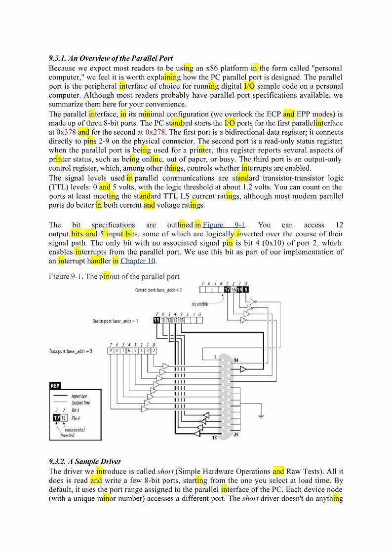
9.2.6. Platform Dependencies
I/O instructions are, by their nature, highly processor dependent. Because they work with the
details of how the processor handles moving data in and out, it is very hard to hide the
differences between systems. As a consequence, much of the source code related to
port I/O is platform-dependent.
Once again, I/O space is memory-mapped. Versions of the port functions are def ined
to work with unsigned long ports.
The curious reader can extract more information from the io.h files, which sometimes def ine
a few architecture-specific functions in addition to those we describe in this chapter. Be
warned that some of these files are rather difficult reading, however.
It's interesting to note that no processor outside the x86 family features a different address
space for ports, even though several of the supported families are shipped with ISA and/or
PCI slots (and both buses implement separate I/O and memory address spaces).
Moreover, some processors (most notably the early Alphas) lack instructions that move one
or two bytes at a time.[4] Therefore, their peripheral chipsets simulate 8-bit and 16-
bit I/Oaccesses by mapping them to special address ranges in the memory address space.
Thus, an inb and an inw instruction that act on the same port are implemented by two 32-
bitmemory reads that operate on different addresses. Fortunately, all of this is hidden from the
device driver writer by the internals of the macros described in this section, but we feel it's
an interesting feature to note. If you want to probe further, look for examples in include/asm-alpha/core_lca.h.
Despite the popularity of I/O ports in the x86 world, the main mechanism used to
communicate with devices is through memory-mapped registers and device memory. Both
are called I/O memory because the difference between registers and memory is transparent tosoftware.
I/O memory is simply a region of RAM-like locations that the device makes available to the
processor over the bus. This memory can be used for a number of purposes, such as holding
video data or Ethernet packets, as well as implementing device registers that behave just
like I/O ports (i.e., they have side effects associated with reading and writing them).
The way to access I/O memory depends on the computer architecture, bus, and device being
used, although the principles are the same everywhere. The discussion in this chapter touches
mainly on ISA and PCI memory, while trying to convey general information as well.
Although access to PCI memory is introduced here, a thorough discussion of PCI is deferred
to Chapter 12.
Depending on the computer platform and bus being used, I/O memory may or may not be
accessed through page tables. When access passes though page tables, the kernel must first
arrange f or the physical address to be visible from your driver, and this usually means that
you must call ioremap before doing any I/O. If no page tables are
needed, I/O memorylocations look pretty much like I/O ports, and you can just read and write
to them using proper wrapper functions.
Whether or not ioremap is required to access I/O memory, direct use of pointers
to I/O memory is discouraged. Even though (as introduced in Section 9.1) I/O memory is
addressed like normal RAM at hardware level, the extra care outlined in the Section
9.1.1 suggests avoiding normal pointers. The wrapper functions used to
access I/O memory are safe on all platforms and are optimized away whenever straight pointer dereferencing can perform the operation.
Therefore, even though dereferencing a pointer works (for now) on the x86, failure to use the
proper macros hinders the portability and readability of the driver.
9.4.1. I/O Memory Allocation and Mapping
I/O memory regions must be allocated prior to use. The interface for allocation
of memory regions (def ined in <linux/ioport.h>) is:
struct resource *request_mem_region(unsigned long start, unsigned long len,
char *name);
This function allocates a memory region of len bytes, starting at start. If all goes well, a non- NULL pointer is returned; otherwise the return value is NULL. All I/O memory allocations
are listed in /proc/iomem.
Memory regions should be freed when no longer needed:
void release_mem_region(unsigned long start, unsigned long len);
There is also an old function for checking I/O memory region availability:
int check_mem_region(unsigned long start, unsigned long len);
But, as with check_region, this function is unsafe and should be avoided.
Allocation of I/O memory is not the only required step before that memory may be accessed.You must also ensure that this I/O memory has been made accessible to the kernel. Getting
at I/O memory is not just a matter of dereferencing a pointer; on many
systems, I/O memory is not directly accessible in this way at all. So a mapping must be set up
first. This is the role of the ioremap function, introduced in Section 8.4 in Chapter 8. The
function is designed specifically to assign virtual addresses to I/O memory regions.
Once equipped with ioremap (and iounmap), a device driver can access
any I/O memory address, whether or not it is directly mapped to virtual address space.Remember, though, that the addresses returned from ioremap should not be dereferenced
directly; instead, accessor functions provided by the kernel should be used. Before we
get into those functions, we'd better review the ioremap prototypes and introduce a few
details that we passed over in the previous chapter.
The functions are called according to the following def inition:
#include <asm/io.h>
void *ioremap(unsigned long phys_addr, unsigned long size);
void *ioremap_nocache(unsigned long phys_addr, unsigned long size);
void iounmap(void * addr);
First of all, you notice the new function ioremap_nocache. We didn't cover it in Chapter 8,
because its meaning is def initely hardware related. Quoting from one of the kernel headers:
"It's useful if some control registers are in such an area, and write combining or read caching
is not desirable." Actually, the function's implementation is identical to ioremap on most
computer platforms: in situations where all of I/O memory is already visible through
noncacheable addresses, there's no reason to implement a separate, noncaching version
of ioremap.
9.4.2. Accessing I/O Memory
On some platforms, you may get away with using the return value from ioremap as a pointer.
Such use is not portable, and, increasingly, the kernel developers have been working toeliminate any such use. The proper way of getting at I/O memory is via a set of functions
(def ined via <asm/io.h>) provided for that purpose.
To read from I/O memory, use one of the following:
unsigned int ioread8(void *addr);
unsigned int ioread16(void *addr);
unsigned int ioread32(void *addr);
Here, addr should be an address obtained from ioremap (perhaps with an integer offset); the
return value is what was read from the given I/O memory.
There is a similar set of functions for writing to I/O memory:
void iowrite8(u8 value, void *addr);
void iowrite16(u16 value, void *addr);
void iowrite32(u32 value, void *addr);
If you must read or write a series of values to a given I/O memory address, you can use the
repeating versions of the functions:
void ioread8_rep(void *addr, void *buf, unsigned long count);
void ioread16_rep(void *addr, void *buf, unsigned long count);
void ioread32_rep(void *addr, void *buf, unsigned long count);
void iowrite8_rep(void *addr, const void *buf, unsigned long count);
void iowrite16_rep(void *addr, const void *buf, unsigned long count);void iowrite32_rep(void *addr, const void *buf, unsigned long count);
In addition, programs can be further optimized by assigning the same register to a source and
destination of a move instruction whenever possible. This is especially important if the
compiler is using other optimizations such as SSA analysis, which artificially generates
additional move instructions in the intermediate code. The most commonly used registers are:
1. CPU cache2. Shift registers
SHIFT REGISTERS
Shift registersIn digital circuits, a shift register is a cascade of flip flops, sharing the same
clock, which has the output of any one but the last flip-flop connected to the "data" input of
the next one in the chain, resulting in a circuit that shifts by one position the one-dimensional
" bit array" stored in it, shifting in the data present at its input and shifting out the last bit in
the array, when enabled to do so by a transition of the clock input. More generally, a shift
register may be multidimensional, such that its "data in" input and stage outputs are
themselves bit arrays: this is implemented simply by running several shift registers of the
same bit-length in parallel.
One of the most common uses of a shift register is to convert between serial and parallel
interfaces. This is useful as many circuits work on groups of bits in parallel, but serial
interfaces are simpler to construct. Shift registers can be used as simple delay circuits.
Several bidirectional shift registers could also be connected in parallel for a hardware
implementation of a stack .
CPU CACHE
A CPU cache is a cache used by the central processing unit of a computer to reduce the
average time to access memory. The cache is a smaller, faster memory which stores copies of
the data from the most frequently used main memory locations. As long as most memory
accesses are cached memory locations, the average latency of memory accesses will be closer
to the cache latency than to the latency of main memory.When the processor needs to read from or write to a location in main memory, it first checks
whether a copy of that data is in the cache. If so, the processor immediately reads from or
writes to the cache, which is much faster than reading from or writing to main memory.
Most modern desktop and server CPUs have at least three independent caches: an instruction
cache to speed up executable instruction fetch, a data cache to speed up data fetch and store,
and a translation lookaside buffer (TLB) used to speed up virtual-to-physical address
translation for both executable instructions and data.
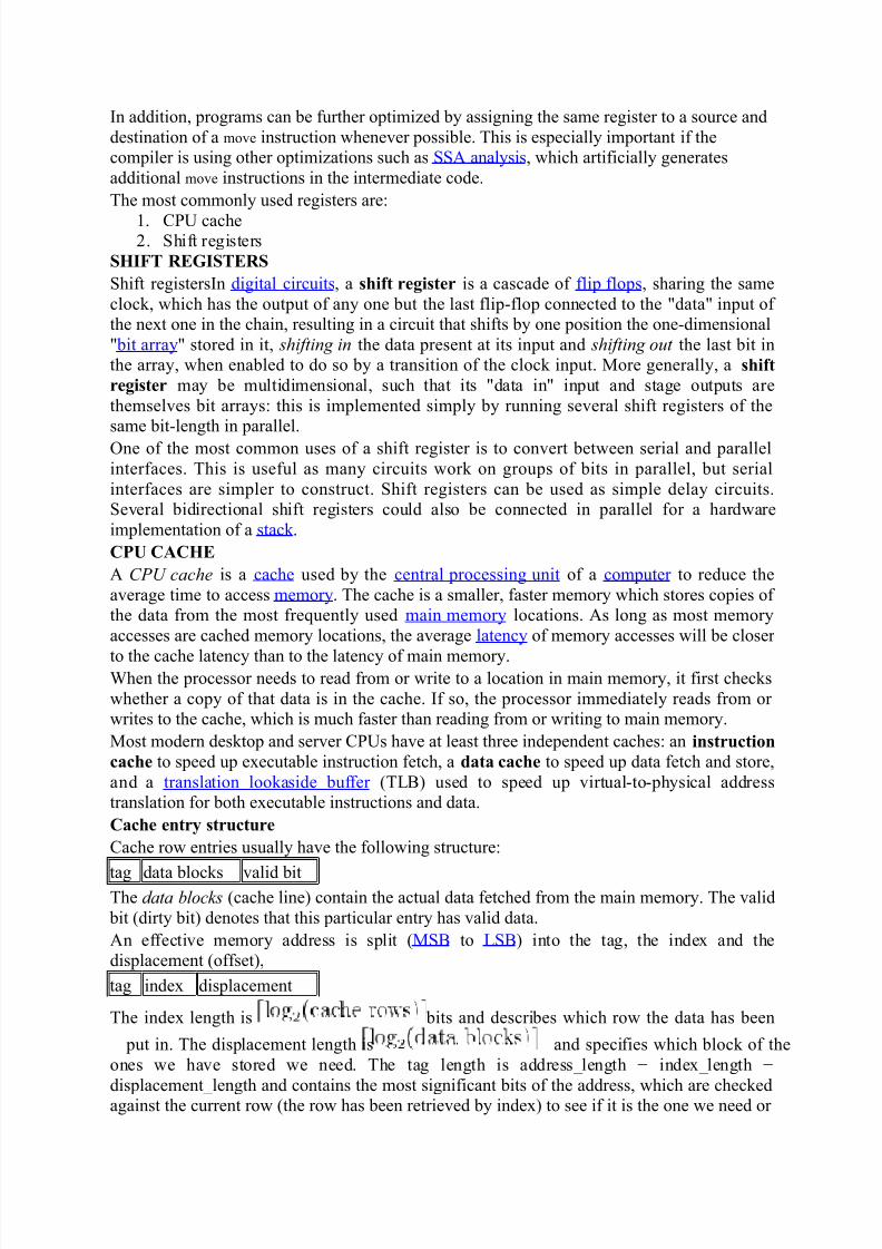
Cache entry structure
Cache row entries usually have the following structure:
tag data blocks valid bitThe data blocks (cache line) contain the actual data fetched from the main memory. The valid
bit (dirty bit) denotes that this particular entry has valid data.
An effective memory address is split (MSB to LSB) into the tag, the index and the
displacement (offset),
tag index displacement
The index length is bits and describes which row the data has been
put in. The displacement length is and specifies which block of the
ones we have stored we need. The tag length is address_length − index_length −
displacement_length and contains the most significant bits of the address, which are checkedagainst the current row (the row has been retrieved by index) to see if it is the one we need or
1) If you use & operator with a register variable then compiler may give an error or warning
(depending upon the compiler you are using), because when we say a variable is a register, it
may be stored in a register instead of memory and accessing address of a register is invalid.
Try below program.
?
int main()
{
register int i = 10;
int *a = &i;
printf("%d", *a);
getchar();
return 0;
}
2) register keyword can be used with pointer variables. Obviously, a register can haveaddress of a memory location. There would not be any problem with the below program.
?
int main()
{
int i = 10;
register int *a = &i;
printf("%d", *a);
getchar();
return 0;
}3) Register is a storage class, and C doesn’t allow multiple storage class specifiers for a
variable. So,register can not be used with static . Try below program.
?
int main()
{
int i = 10;
register static int *a = &i;
printf("%d", *a);
getchar();
return 0;
}
4) There is no limit on number of register variables in a C program, but the point is compiler
may put some variables in register and some not.
Functions
When the compiler reaches the function definition, it generates machine instructions to
the functionality, and reserves enough program memory to hold the statements in the
function. The
address of the function is available through the symbol table.
A function definition includes a statement block that contains all function statements. Even if
a
function has only a single executable statement, it must be enclosed in a statement block.Embedded C supports function prototypes. Function prototype declarations ensure that the
compiler knows about a function and its parameter types, even if its definition has yet to
appear in
the compiler's input. Prototypes assist in checking forward calls. The function name is
recorded as
an identifier, and is therefore known when invoked in code prior to its definition.
Header files of function prototypes provide the foundation for using libraries.
The syntax for a function call in C is the function name and a list of actual parameters
surrounded
by parentheses.
Function calling is one area in which embedded C differs substantially from traditional C.The way
that parameters are passed differs significantly, as well as the permitted number of
parameters.
Functions that produce extensive side effects are harder to maintain and debug, especially for
members of a development team. To safely use abstract functions, you need to know only the
data
that goes in and comes out — the function interface. When a function produces side effects,
you
need to know about the interface and behaviour to use it safely.
Some C programmers insist that functions that just produce side effects should return a value
to
indicate success, failure, or error. Since ROM space is at a premium, the code needed to
evaluate the
return status is a luxury.
Function Parameters
C for embedded processors places some unique restrictions on function calls. Some compilers
restrict the number of parameters that can be passed to a function. Two byte-sized parameters
(or
one 16-bit parameter) can be passed within the common processor registers (accumulator and
index
register).To pass by reference, pass a pointer as usual. See information on pointers in Section 6.7.1,
Pointers, for extra information about the relative cost of using pointers.
A function with no parameters can be declared with an empty parameter list.
int myFunc()
However, it is good practice to specify that the function has no parameters with the void
parameter
type.
int myFunc(void)
In embedded programs, main() does not accept any parameters
WHY USE FUNCTIONS
Two reasons :(i) Writing functions avoids rewriting the same code over and over. Suppose that there is
a section of code in a program that calculates area of a triangle. If, later in the program
we want to calculate the area of a different triangle we wont like to write the same
instructions all over again. Instead we would prefer to jump to a ‘section of code’ that
calculates area and then jump back to the place from where you left off. This section of
code is nothing but a function.
(ii) Using functions it becomes easier to write programs and keep track of what they aredoing. If the operation of a program can be divided in to separate activities, and each
activity placed in a different function, then each could be written and checked more or
less independently. Separating the code in to modular functions also makes the program
easier to design and understand.
CALL BY VALUE
In the preceding examples we have seen that whenever we called a function we have always
passed the values of variables to the called function. Such function calls are called ‘calls by
value’ by this what it meant is that on calling a function we are passing values of variables to
it.
The example of call by value are shown below ;
sum = calsum (a, b, c);f = factr (a);
In this method the value of each of the actual arguments in the calling function is copied into
corresponding formal arguments of the called function. With this method the changes made
to the formal arguments in the called function have no effect on the values of actual argument
in the calling function. the following program illustrates this
main ( )
{
int a = 10, b=20;
swapy (a,b);
printf (“\na = % d b = % d”, a,b);
}
swapy (int x, int y)
{
int t;
t = x;
x = y;
y = t;
printf ( “\n x = % d y = % d” , x, y);
}
The output of the above program would be;
x = 20 y = 10a =10 b =20
CALL BY REFERENCE
In the second method the addresses of actual arguments in the calling function are copied in
to formal arguments of the called function. This means that using these addresses we would
have an access to the actual arguments and hence we would be able to manipulate them the
Shared memory can also be used as an Inter Process Communication (IPC)
mechanism, with two or more processes exchanging information via memory
common to all of them. Linux supports the Unix TM System V shared memory IPC.
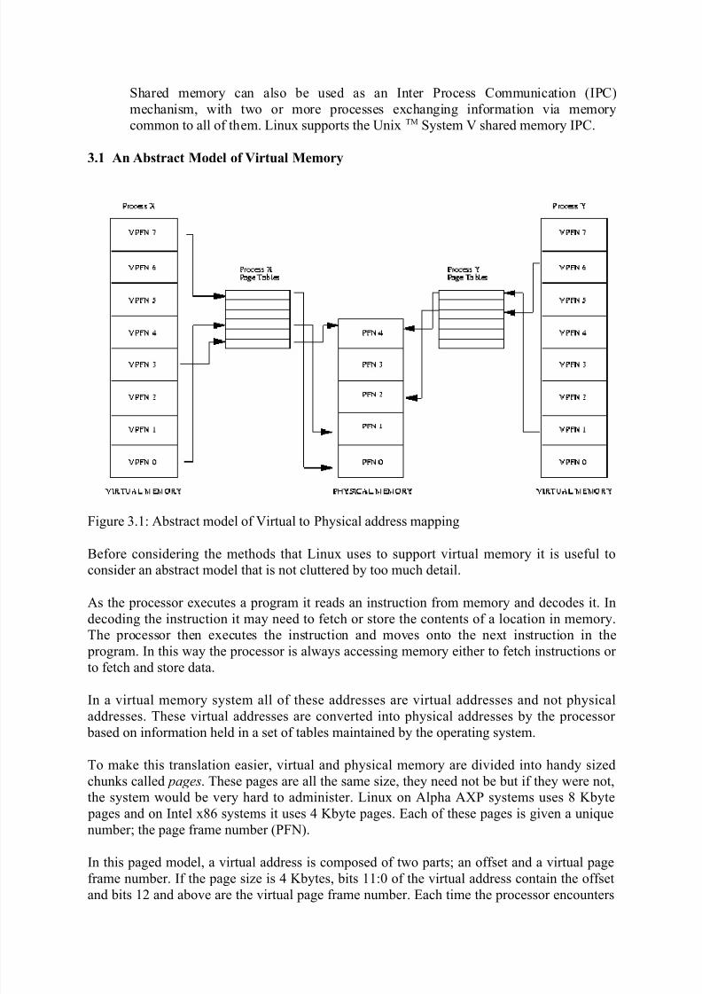
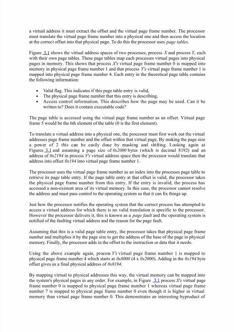
3.1 An Abstract Model of Virtual Memory
Figure 3.1: Abstract model of Virtual to Physical address mapping
Before considering the methods that Linux uses to support virtual memory it is useful to
consider an abstract model that is not cluttered by too much detail.
As the processor executes a program it reads an instruction from memory and decodes it. In
decoding the instruction it may need to fetch or store the contents of a location in memory.
The processor then executes the instruction and moves onto the next instruction in the
program. In this way the processor is always accessing memory either to fetch instructions or
to fetch and store data.
In a virtual memory system all of these addresses are virtual addresses and not physicaladdresses. These virtual addresses are converted into physical addresses by the processor
based on information held in a set of tables maintained by the operating system.
To make this translation easier, virtual and physical memory are divided into handy sized
chunks called pages. These pages are all the same size, they need not be but if they were not,
the system would be very hard to administer. Linux on Alpha AXP systems uses 8 Kbyte
pages and on Intel x86 systems it uses 4 Kbyte pages. Each of these pages is given a unique
number; the page frame number (PFN).
In this paged model, a virtual address is composed of two parts; an offset and a virtual page
frame number. If the page size is 4 Kbytes, bits 11:0 of the virtual address contain the offset
and bits 12 and above are the virtual page frame number. Each time the processor encounters
a virtual address it must extract the offset and the virtual page frame number. The processor
must translate the virtual page frame number into a physical one and then access the location
at the correct offset into that physical page. To do this the processor uses page tables.
Figure 3.1 shows the virtual address spaces of two processes, process X and process Y , each
with their own page tables. These page tables map each processes virtual pages into physical pages in memory. This shows that process X's virtual page frame number 0 is mapped into
memory in physical page frame number 1 and that process Y's virtual page frame number 1 is
mapped into physical page frame number 4. Each entry in the theoretical page table contains
the following information:
• Valid flag. This indicates if this page table entry is valid,
• The physical page frame number that this entry is describing,
• Access control information. This describes how the page may be used. Can it be
written to? Does it contain executable code?
The page table is accessed using the virtual page frame number as an offset. Virtual pageframe 5 would be the 6th element of the table (0 is the first element).
To translate a virtual address into a physical one, the processor must first work out the virtual
addresses page frame number and the offset within that virtual page. By making the page size
a power of 2 this can be easily done by masking and shifting. Looking again at
Figures 3.1 and assuming a page size of 0x2000 bytes (which is decimal 8192) and an
address of 0x2194 in process Y's virtual address space then the processor would translate that
address into offset 0x194 into virtual page frame number 1.
The processor uses the virtual page frame number as an index into the processes page table to
retrieve its page table entry. If the page table entry at that offset is valid, the processor takes
the physical page frame number from this entry. If the entry is invalid, the process has
accessed a non-existent area of its virtual memory. In this case, the processor cannot resolve
the address and must pass control to the operating system so that it can fix things up.
Just how the processor notifies the operating system that the correct process has attempted to
access a virtual address for which there is no valid translation is specific to the processor.
However the processor delivers it, this is known as a page fault and the operating system is
notified of the faulting virtual address and the reason for the page fault.
Assuming that this is a valid page table entry, the processor takes that physical page framenumber and multiplies it by the page size to get the address of the base of the page in physical
memory. Finally, the processor adds in the offset to the instruction or data that it needs.
Using the above example again, process Y's virtual page frame number 1 is mapped to
physical page frame number 4 which starts at 0x8000 (4 x 0x2000). Adding in the 0x194 byte
offset gives us a final physical address of 0x8194.
By mapping virtual to physical addresses this way, the virtual memory can be mapped into
the system's physical pages in any order. For example, in Figure 3.1 process X's virtual page
frame number 0 is mapped to physical page frame number 1 whereas virtual page frame
number 7 is mapped to physical page frame number 0 even though it is higher in virtualmemory than virtual page frame number 0. This demonstrates an interesting byproduct of
virtual memory; the pages of virtual memory do not have to be present in physical memory in
any particular order.
3.1.1 Demand Paging
As there is much less physical memory than virtual memory the operating system must becareful that it does not use the physical memory inefficiently. One way to save physical
memory is to only load virtual pages that are currently being used by the executing program.
For example, a database program may be run to query a database. In this case not all of the
database needs to be loaded into memory, just those data records that are being examined. If
the database query is a search query then it does not make sense to load the code from the
database program that deals with adding new records. This technique of only loading virtual
pages into memory as they are accessed is known as demand paging.
When a process attempts to access a virtual address that is not currently in memory the
processor cannot find a page table entry for the virtual page referenced. For example, in
Figure 3.1 there is no entry in process X's page table for virtual page frame number 2 and soif process X attempts to read from an address within virtual page frame number 2 the
processor cannot translate the address into a physical one. At this point the processor notifies
the operating system that a page fault has occurred.
If the faulting virtual address is invalid this means that the process has attempted to access a
virtual address that it should not have. Maybe the application has gone wrong in some way,
for example writing to random addresses in memory. In this case the operating system will
terminate it, protecting the other processes in the system from this rogue process.
If the faulting virtual address was valid but the page that it refers to is not currently in
memory, the operating system must bring the appropriate page into memory from the image
on disk. Disk access takes a long time, relatively speaking, and so the process must wait quite
a while until the page has been fetched. If there are other processes that could run then the
operating system will select one of them to run. The fetched page is written into a free
physical page frame and an entry for the virtual page frame number is added to the processes
page table. The process is then restarted at the machine instruction where the memory fault
occurred. This time the virtual memory access is made, the processor can make the virtual to
physical address translation and so the process continues to run.
Linux uses demand paging to load executable images into a processes virtual memory.
Whenever a command is executed, the file containing it is opened and its contents aremapped into the processes virtual memory. This is done by modifying the data structures
describing this processes memory map and is known as memory mapping . However, only the
first part of the image is actually brought into physical memory. The rest of the image is left
on disk. As the image executes, it generates page faults and Linux uses the processes memory
map in order to determine which parts of the image to bring into memory for execution.
3.1.2 Swapping
If a process needs to bring a virtual page into physical memory and there are no free physical
pages available, the operating system must make room for this page by discarding another
If the page to be discarded from physical memory came from an image or data file and has
not been written to then the page does not need to be saved. Instead it can be discarded and if
the process needs that page again it can be brought back into memory from the image or data
file.
However, if the page has been modified, the operating system must preserve the contents of that page so that it can be accessed at a later time. This type of page is known as a dirty page
and when it is removed from memory it is saved in a special sort of file called the swap file.
Accesses to the swap file are very long relative to the speed of the processor and physical
memory and the operating system must juggle the need to write pages to disk with the need to
retain them in memory to be used again.
If the algorithm used to decide which pages to discard or swap (the swap algorithm is not
efficient then a condition known as thrashing occurs. In this case, pages are constantly being
written to disk and then being read back and the operating system is too busy to allow much
real work to be performed. If, for example, physical page frame number 1 in Figure 3.1 is
being regularly accessed then it is not a good candidate for swapping to hard disk. The set of pages that a process is currently using is called the working set . An efficient swap scheme
would make sure that all processes have their working set in physical memory.
Linux uses a Least Recently Used (LRU) page aging technique to fairly choose pages which
might be removed from the system. This scheme involves every page in the system having an
age which changes as the page is accessed. The more that a page is accessed, the younger it
is; the less that it is accessed the older and more stale it becomes. Old pages are good
candidates for swapping.
3.1.3 Shared Virtual Memory
Virtual memory makes it easy for several processes to share memory. All memory access are
made via page tables and each process has its own separate page table. For two processes
sharing a physical page of memory, its physical page frame number must appear in a page
table entry in both of their page tables.
Figure 3.1 shows two processes that each share physical page frame number 4. For
process X this is virtual page frame number 4 whereas for process Y this is virtual page frame
number 6. This illustrates an interesting point about sharing pages: the shared physical page
does not have to exist at the same place in virtual memory for any or all of the processes
sharing it.
3.1.4 Physical and Virtual Addressing Modes
It does not make much sense for the operating system itself to run in virtual memory. This
would be a nightmare situation where the operating system must maintain page tables for
itself. Most multi-purpose processors support the notion of a physical address mode as well
as a virtual address mode. Physical addressing mode requires no page tables and the
processor does not attempt to perform any address translations in this mode. The Linux
kernel is linked to run in physical address space.
The Alpha AXP processor does not have a special physical addressing mode. Instead, itdivides up the memory space into several areas and designates two of them as physically
mapped addresses. This kernel address space is known as KSEG address space and it
encompasses all addresses upwards from 0xfffffc0000000000. In order to execute from code
linked in KSEG (by definition, kernel code) or access data there, the code must be executing
in kernel mode. The Linux kernel on Alpha is linked to execute from
address 0xfffffc0000310000.
3.1.5 Access Control
The page table entries also contain access control information. As the processor is already
using the page table entry to map a processes virtual address to a physical one, it can easily
use the access control information to check that the process is not accessing memory in a way
that it should not.
There are many reasons why you would want to restrict access to areas of memory. Some
memory, such as that containing executable code, is naturally read only memory; the
operating system should not allow a process to write data over its executable code. By
contrast, pages containing data can be written to but attempts to execute that memory asinstructions should fail. Most processors have at least two modes of
execution: kernel and user . You would not want kernel code executing by a user or kernel
data structures to be accessible except when the processor is running in kernel mode.
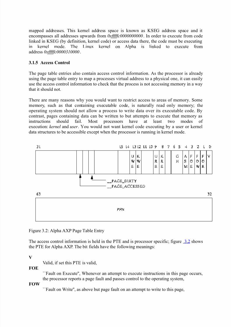
Figure 3.2: Alpha AXP Page Table Entry
The access control information is held in the PTE and is processor specific; figure 3.2 shows
the PTE for Alpha AXP. The bit fields have the following meanings:
V
Valid, if set this PTE is valid,
FOE
``Fault on Execute'', Whenever an attempt to execute instructions in this page occurs,
the processor reports a page fault and passes control to the operating system,
FOW
``Fault on Write'', as above but page fault on an attempt to write to this page,
All of the physical pages in the system are described by the mem_map data structure which is
a list of mem_map_t
1 structures which is initialized at boot time. Each mem_map_t describes a single physical
page in the system. Important fields (so far as memory management is concerned) are:
count
This is a count of the number of users of this page. The count is greater than one when
the page is shared between many processes,
age
This field describes the age of the page and is used to decide if the page is a good
candidate for discarding or swapping,
map_nr
This is the physical page frame number that this mem_map_t describes.
The free_area vector is used by the page allocation code to find and free pages. The whole
buffer management scheme is supported by this mechanism and so far as the code isconcerned, the size of the page and physical paging mechanisms used by the processor are
irrelevant.
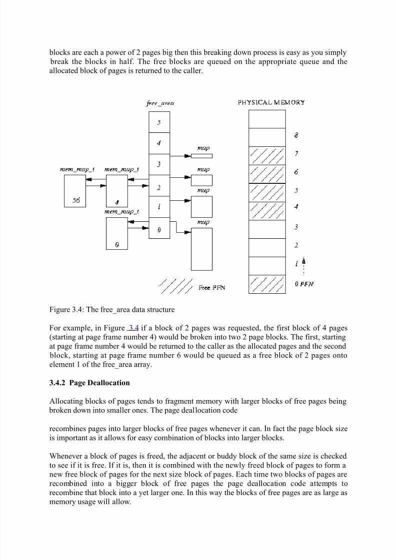
Each element of free_area contains information about blocks of pages. The first element in
the array describes single pages, the next blocks of 2 pages, the next blocks of 4 pages and so
on upwards in powers of two. The list element is used as a queue head and has pointers to
the page data structures in the mem_map array. Free blocks of pages are queued here. map is
a pointer to a bitmap which keeps track of allocated groups of pages of this size. Bit N of the
bitmap is set if the Nth block of pages is free.
Figure free-area-figure shows the free_area structure. Element 0 has one free page (page
frame number 0) and element 2 has 2 free blocks of 4 pages, the first starting at page frame
number 4 and the second at page frame number 56.
3.4.1 Page Allocation
Linux uses the Buddy algorithm 2 to effectively allocate and deallocate blocks of pages. The
page allocation code
attempts to allocate a block of one or more physical pages. Pages are allocated in blocks
which are powers of 2 in size. That means that it can allocate a block 1 page, 2 pages, 4 pagesand so on. So long as there are enough free pages in the system to grant this request
(nr_free_pages min_free_pages) the allocation code will search the free_area for a block
of pages of the size requested. Each element of thefree_area has a map of the allocated and
free blocks of pages for that sized block. For example, element 2 of the array has a memory
map that describes free and allocated blocks each of 4 pages long.
The allocation algorithm first searches for blocks of pages of the size requested. It follows the
chain of free pages that is queued on the list element of the free_area data structure. If no
blocks of pages of the requested size are free, blocks of the next size (which is twice that of
the size requested) are looked for. This process continues until all of the free_area has been
searched or until a block of pages has been found. If the block of pages found is larger thanthat requested it must be broken down until there is a block of the right size. Because the
For example, in Figure 3.4, if page frame number 1 were to be freed, then that would be
combined with the already free page frame number 0 and queued onto element 1 of
the free_area as a free block of size 2 pages.
3.5 Memory Mapping
When an image is executed, the contents of the executable image must be brought into the
processes virtual address space. The same is also true of any shared libraries that the
executable image has been linked to use. The executable file is not actually brought into
physical memory, instead it is merely linked into the processes virtual memory. Then, as the
parts of the program are referenced by the running application, the image is brought into
memory from the executable image. This linking of an image into a processes virtual address
space is known as memory mapping.
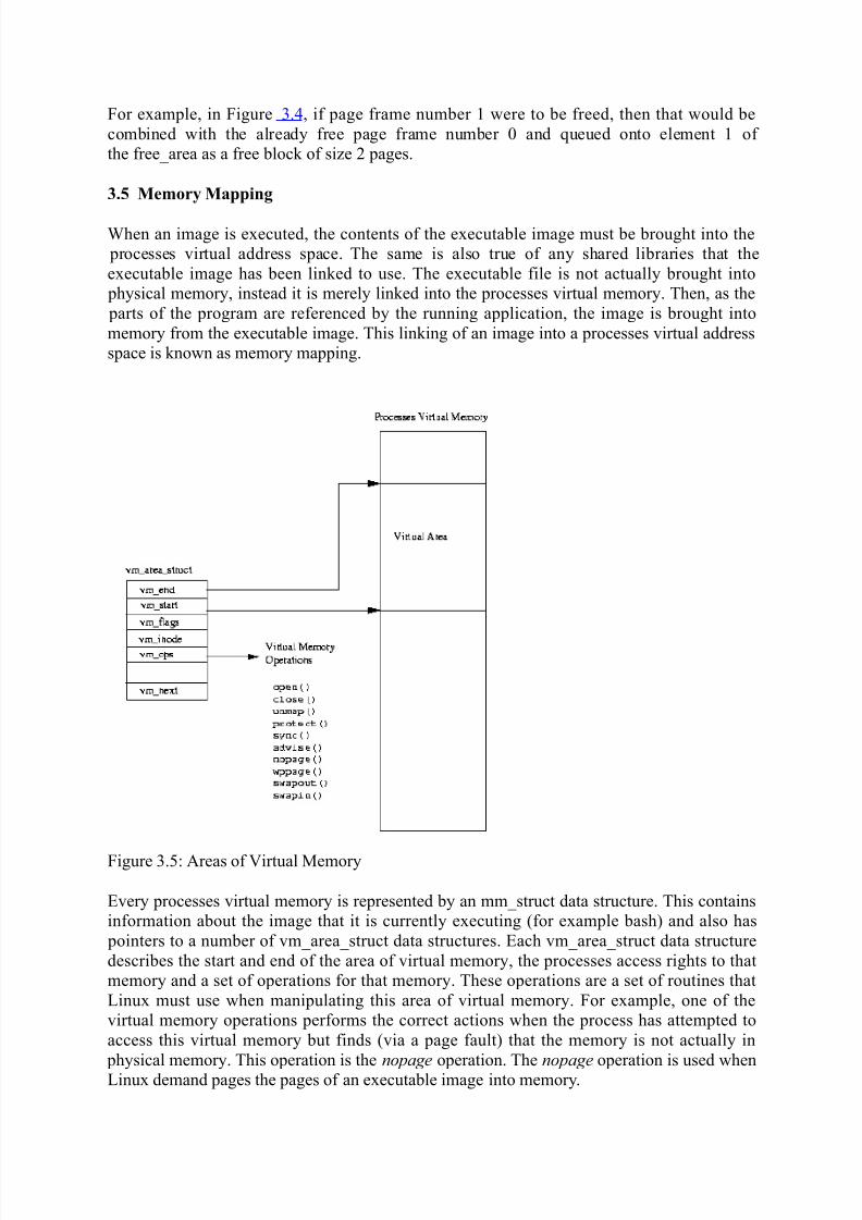
Figure 3.5: Areas of Virtual Memory
Every processes virtual memory is represented by an mm_struct data structure. This contains
information about the image that it is currently executing (for example bash) and also has
pointers to a number of vm_area_struct data structures. Each vm_area_struct data structure
describes the start and end of the area of virtual memory, the processes access rights to that
memory and a set of operations for that memory. These operations are a set of routines that
Linux must use when manipulating this area of virtual memory. For example, one of the
virtual memory operations performs the correct actions when the process has attempted to
access this virtual memory but finds (via a page fault) that the memory is not actually in
physical memory. This operation is the nopage operation. The nopage operation is used whenLinux demand pages the pages of an executable image into memory.
When an executable image is mapped into a processes virtual address a set
of vm_area_struct data structures is generated. Each vm_area_struct data structure represents
a part of the executable image; the executable code, initialized data (variables), unitialized
data and so on. Linux supports a number of standard virtual memory operations and as
the vm_area_struct data structures are created, the correct set of virtual memory operations
are associated with them.
3.6 Demand Paging
Once an executable image has been memory mapped into a processes virtual memory it can
start to execute. As only the very start of the image is physically pulled into memory it will
soon access an area of virtual memory that is not yet in physical memory. When a process
accesses a virtual address that does not have a valid page table entry, the processor will report
a page fault to Linux.
The page fault describes the virtual address where the page fault occurred and the type of
memory access that caused.
Linux must find the vm_area_struct that represents the area of memory that the page fault
occurred in. As searching through the vm_area_struct data structures is critical to the efficient
handling of page faults, these are linked together in an AVL (Adelson-Velskii and Landis) tree
structure. If there is no vm_area_struct data structure for this faulting virtual address, this
process has accessed an illegal virtual address. Linux will signal the process, sending
a SIGSEGV signal, and if the process does not have a handler for that signal it will be
terminated.
Linux next checks the type of page fault that occurred against the types of accesses allowed
for this area of virtual memory. If the process is accessing the memory in an illegal way, say
writing to an area that it is only allowed to read from, it is also signalled with a memory error.
Now that Linux has determined that the page fault is legal, it must deal with it.
Linux must differentiate between pages that are in the swap file and those that are part of an
executable image on a disk somewhere. It does this by using the page table entry for this
faulting virtual address.
If the page's page table entry is invalid but not empty, the page fault is for a page currently
being held in the swap file. For Alpha AXP page table entries, these are entries which do nothave their valid bit set but which have a non-zero value in their PFN field. In this case the
PFN field holds information about where in the swap (and which swap file) the page is being
held. How pages in the swap file are handled is described later in this chapter.
Not all vm_area_struct data structures have a set of virtual memory operations and even those
that do may not have a nopage operation. This is because by default Linux will fix up the
access by allocating a new physical page and creating a valid page table entry for it. If there
is a nopage operation for this area of virtual memory, Linux will use it.
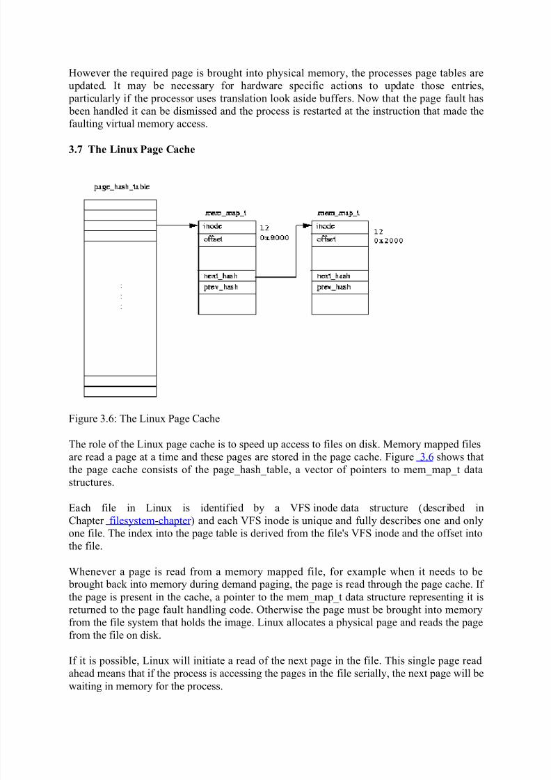
The generic Linux nopage operation is used for memory mapped executable images and it
uses the page cache to bring the required image page into physical memory.
Over time the page cache grows as images are read and executed. Pages will be removed
from the cache as they are no longer needed, say as an image is no longer being used by any
process. As Linux uses memory it can start to run low on physical pages. In this case Linux
will reduce the size of the page cache.
3.8 Swapping Out and Discarding Pages
When physical memory becomes scarce the Linux memory management subsystem must
attempt to free physical pages. This task falls to the kernel swap daemon (kswapd ).
The kernel swap daemon is a special type of process, a kernel thread. Kernel threads are
processes have no virtual memory, instead they run in kernel mode in the physical address
space. The kernel swap daemon is slightly misnamed in that it does more than merely swap
pages out to the system's swap files. Its role is make sure that there are enough free pages in
the system to keep the memory management system operating efficiently.
The Kernel swap daemon (kswapd ) is started by the kernel init process at startup time and sitswaiting for the kernel swap timer to periodically expire.
Every time the timer expires, the swap daemon looks to see if the number of free pages in the
system is getting too low. It uses two variables, free_pages_high and free_pages_low to
decide if it should free some pages. So long as the number of free pages in the system
remains above free_pages_high, the kernel swap daemon does nothing; it sleeps again until
its timer next expires. For the purposes of this check the kernel swap daemon takes into
account the number of pages currently being written out to the swap file. It keeps a count of
these in nr_async_pages; this is incremented each time a page is queued waiting to be written
out to the swap file and decremented when the write to the swap device has
completed. free_pages_low and free_pages_high are set at system startup time and are related
to the number of physical pages in the system. If the number of free pages in the system has
fallen below free_pages_high or worse still free_pages_low, the kernel swap daemon will try
three ways to reduce the number of physical pages being used by the system:
Reducing the size of the buffer and page caches,
Swapping out System V shared memory pages,
Swapping out and discarding pages.
If the number of free pages in the system has fallen below free_pages_low, the kernel swap
daemon will try to free 6 pages before it next runs. Otherwise it will try to free 3 pages. Eachof the above methods are tried in turn until enough pages have been freed. The kernel swap
daemon remembers which method it was using the last time that it attempted to free physical
pages. Each time it runs it will start trying to free pages using this last successful method.
After it has free sufficient pages, the swap daemon sleeps again until its timer expires. If the
reason that the kernel swap daemon freed pages was that the number of free pages in the
system had fallen below free_pages_low, it only sleeps for half its usual time. Once the
number of free pages is more than free_pages_low the kernel swap daemon goes back to
sleeping longer between checks.
3.8.1 Reducing the Size of the Page and Buffer Caches
The pages held in the page and buffer caches are good candidates for being freed into
the free_area vector. The Page Cache, which contains pages of memory mapped files, may
contain unneccessary pages that are filling up the system's memory. Likewise the Buffer
Cache, which contains buffers read from or being written to physical devices, may also
contain unneeded buffers. When the physical pages in the system start to run out, discarding
pages from these caches is relatively easy as it requires no writing to physical devices (unlikeswapping pages out of memory). Discarding these pages does not have too many harmful
side effects other than making access to physical devices and memory mapped files slower.
However, if the discarding of pages from these caches is done fairly, all processes will suffer
equally.
Every time the Kernel swap daemon tries to shrink these caches
it examines a block of pages in the mem_map page vector to see if any can be discarded from
physical memory. The size of the block of pages examined is higher if the kernel swap
daemon is intensively swapping; that is if the number of free pages in the system has fallen
dangerously low. The blocks of pages are examined in a cyclical manner; a different block of pages is examined each time an attempt is made to shrink the memory map. This is known as
the clock algorithm as, rather like the minute hand of a clock, the whole mem_map page
vector is examined a few pages at a time.
Each page being examined is checked to see if it is cached in either the page cache or the
buffer cache. You should note that shared pages are not considered for discarding at this time
and that a page cannot be in both caches at the same time. If the page is not in either cache
then the next page in the mem_map page vector is examined.
Pages are cached in the buffer cache (or rather the buffers within the pages are cached) to
make buffer allocation and deallocation more efficient. The memory map shrinking code tries
to free the buffers that are contained within the page being examined.
If all the buffers are freed, then the pages that contain them are also be freed. If the examined
page is in the Linux page cache, it is removed from the page cache and freed.
When enough pages have been freed on this attempt then the kernel swap daemon will wait
until the next time it is periodically woken. As none of the freed pages were part of any
process's virtual memory (they were cached pages), then no page tables need updating. If
there were not enough cached pages discarded then the swap daemon will try to swap out
some shared pages.
3.8.2 Swapping Out System V Shared Memory Pages
System V shared memory is an inter-process communication mechanism which allows two or
more processes to share virtual memory in order to pass information amongst themselves.
How processes share memory in this way is described in more detail in Chapter IPC-chapter .
For now it is enough to say that each area of System V shared memory is described by
a shmid_ds data structure. This contains a pointer to a list of vm_area_struct data structures,
one for each process sharing this area of virtual memory. The vm_area_struct data structures
describe where in each processes virtual memory this area of System V shared memory goes.
Each vm_area_struct data structure for this System V shared memory is linked together usingthe vm_next_shared and vm_prev_shared pointers. Eachshmid_ds data structure also contains
a list of page table entries each of which describes the physical page that a shared virtual page
maps to.
The kernel swap daemon also uses a clock algorithm when swapping out System V shared
memory pages.
. Each time it runs it remembers which page of which shared virtual memory area it last
swapped out. It does this by keeping two indices, the first is an index into the set
of shmid_ds data structures, the second into the list of page table entries for this area of
System V shared memory. This makes sure that it fairly victimizes the areas of System V
shared memory.
As the physical page frame number for a given virtual page of System V shared memory is
contained in the page tables of all of the processes sharing this area of virtual memory, the
kernel swap daemon must modify all of these page tables to show that the page is no longer
in memory but is now held in the swap file. For each shared page it is swapping out, the
kernel swap daemon finds the page table entry in each of the sharing processes page tables(by following a pointer from each vm_area_struct data structure). If this processes page table
entry for this page of System V shared memory is valid, it converts it into an invalid but
swapped out page table entry and reduces this (shared) page's count of users by one. The
format of a swapped out System V shared page table entry contains an index into the set
of shmid_dsdata structures and an index into the page table entries for this area of System V
shared memory.
If the page's count is zero after the page tables of the sharing processes have all been
modified, the shared page can be written out to the swap file. The page table entry in the list
pointed at by the shmid_dsdata structure for this area of System V shared memory is replaced
by a swapped out page table entry. A swapped out page table entry is invalid but contains an
index into the set of open swap files and the offset in that file where the swapped out page
can be found. This information will be used when the page has to be brought back into
physical memory.
3.8.3 Swapping Out and Discarding Pages
The swap daemon looks at each process in the system in turn to see if it is a good candidate
for swapping.
Good candidates are processes that can be swapped (some cannot) and that have one or more pages which can be swapped or discarded from memory. Pages are swapped out of physical
memory into the system's swap files only if the data in them cannot be retrieved another way.
A lot of the contents of an executable image come from the image's file and can easily be re-
read from that file. For example, the executable instructions of an image will never be
modified by the image and so will never be written to the swap file. These pages can simply
be discarded; when they are again referenced by the process, they will be brought back into
memory from the executable image.
Once the process to swap has been located, the swap daemon looks through all of its virtual
memory regions looking for areas which are not shared or locked.
Linux does not swap out all of the swappable pages of the process that it has selected; instead
it removes only a small number of pages.
Pages cannot be swapped or discarded if they are locked in memory.
The Linux swap algorithm uses page aging. Each page has a counter (held inthe mem_map_t data structure) that gives the Kernel swap daemon some idea whether or not
a page is worth swapping. Pages age when they are unused and rejuvinate on access; the
swap daemon only swaps out old pages. The default action when a page is first allocated, is
to give it an initial age of 3. Each time it is touched, it's age is increased by 3 to a maximum
of 20. Every time the Kernel swap daemon runs it ages pages, decrementing their age by 1.
These default actions can be changed and for this reason they (and other swap related
information) are stored in the swap_control data structure.
If the page is old (age = 0), the swap daemon will process it further. Dirty pages are pages
which can be swapped out. Linux uses an architecture specific bit in the PTE to describe
pages this way (see Figure 3.2). However, not all dirty pages are necessarily written to theswap file. Every virtual memory region of a process may have its own swap operation
(pointed at by the vm_ops pointer in thevm_area_struct) and that method is used. Otherwise,
the swap daemon will allocate a page in the swap file and write the page out to that device.
The page's page table entry is replaced by one which is marked as invalid but which contains
information about where the page is in the swap file. This is an offset into the swap file where
the page is held and an indication of which swap file is being used. Whatever the swap
method used, the original physical page is made free by putting it back into the free_area.
Clean (or rather not dirty) pages can be discarded and put back into the free_area for re-use.
If enough of the swappable processes pages have been swapped out or discarded, the swap
daemon will again sleep. The next time it wakes it will consider the next process in the
system. In this way, the swap daemon nibbles away at each processes physical pages until the
system is again in balance. This is much fairer than swapping out whole processes.
3.9 The Swap Cache
When swapping pages out to the swap files, Linux avoids writing pages if it does not have to.
There are times when a page is both in a swap file and in physical memory. This happens
when a page that was swapped out of memory was then brought back into memory when it
was again accessed by a process. So long as the page in memory is not written to, the copy inthe swap file remains valid.
Linux uses the swap cache to track these pages. The swap cache is a list of page table entries,
one per physical page in the system. This is a page table entry for a swapped out page and
describes which swap file the page is being held in together with its location in the swap file.
If a swap cache entry is non-zero, it represents a page which is being held in a swap file that
has not been modified. If the page is subsequently modified (by being written to), its entry is
removed from the swap cache.
When Linux needs to swap a physical page out to a swap file it consults the swap cache and,
if there is a valid entry for this page, it does not need to write the page out to the swap file.
This is because the page in memory has not been modified since it was last read from the
swap file.
The entries in the swap cache are page table entries for swapped out pages. They are marked
as invalid but contain information which allow Linux to find the right swap file and the right
page within that swap file.
3.10 Swapping Pages In
The dirty pages saved in the swap files may be needed again, for example when an
application writes to an area of virtual memory whose contents are held in a swapped out
physical page. Accessing a page of virtual memory that is not held in physical memory causes
a page fault to occur. The page fault is the processor signalling the operating system that it
cannot translate a virtual address into a physical one. In this case this is because the page
table entry describing this page of virtual memory was marked as invalid when the page was
swapped out. The processor cannot handle the virtual to physical address translation and so
hands control back to the operating system describing as it does so the virtual address thatfaulted and the reason for the fault. The format of this information and how the processor
passes control to the operating system is processor specific.
The processor specific page fault handling code must locate the vm_area_struct data structure
that describes the area of virtual memory that contains the faulting virtual address. It does this
by searching thevm_area_struct data structures for this process until it finds the one
containing the faulting virtual address. This is very time critical code and a
processes vm_area_struct data structures are so arranged as to make this search take as little
time as possible.
Having carried out the appropriate processor specific actions and found that the faulting
virtual address is for a valid area of virtual memory, the page fault processing becomes
generic and applicable to all processors that Linux runs on.
The generic page fault handling code looks for the page table entry for the faulting virtual
address. If the page table entry it finds is for a swapped out page, Linux must swap the page
back into physical memory. The format of the page table entry for a swapped out page is
processor specific but all processors mark these pages as invalid and put the information
neccessary to locate the page within the swap file into the page table entry. Linux needs this
information in order to bring the page back into physical memory.
At this point, Linux knows the faulting virtual address and has a page table entry containing
information about where this page has been swapped to. The vm_area_struct data structure
may contain a pointer to a routine which will swap any page of the area of virtual memory
that it describes back into physical memory. This is its swapin operation. If there is
a swapin operation for this area of virtual memory then Linux will use it. This is, in fact, how
swapped out System V shared memory pages are handled as it requires special handling
because the format of a swapped out System V shared page is a little different from that of an
ordinairy swapped out page. There may not be a swapin operation, in which case Linux will
assume that this is an ordinairy page that does not need to be specially handled.
It allocates a free physical page and reads the swapped out page back from the swap file.
Information telling it where in the swap file (and which swap file) is taken from the the
invalid page table entry.
If the access that caused the page fault was not a write access then the page is left in the swap
cache and its page table entry is not marked as writable. If the page is subsequently writtento, another page fault will occur and, at that point, the page is marked as dirty and its entry is
removed from the swap cache. If the page is not written to and it needs to be swapped out
again, Linux can avoid the write of the page to its swap file because the page is already in the
swap file.
If the access that caused the page to be brought in from the swap file was a write operation,
this page is removed from the swap cache and its page table entry is marked as both dirty and
writable.
Memory-Mapped I/O:
Memory-Mapped I/O is a mechanism by which the processor performs I/O access by using
memory access techniques. This is often put into effect because the memory bus is frequently
much faster then the I/O bus. Another reason that memory mapped I/O might be used is that
the architecture in use does not have a separate I/O bus.
In memory mapped IO, certain range of CPU's address space is kept aside for the external
peripherals. These locations can be accessed using the same instructions as used for other
memory accesses. But instead, the read/writes to these addresses are interpreted as access to
device rather than a location on the main memory.
A CPU may expect a particular device at a fixed location or can dynamically assign a space
for it.
The way this works is that memory interfaces are often designed as a bus (a sharedcommunications resource), where many devices are attached. These devices are usually
arranged as master and slave devices, where a master device can send and receive data from
any of the slave devices. A typical system would have:
• A CPU as the master
• One or more RAM and/or ROM devices for program code and data storage
• Peripheral devices for interfacing with the outside world. Examples of these might be
a UART (serial communications), Display device or Input device
MEMORY ALLOCATION (AUTOMATIC, STATIC & DYNAMIC)
The C programming language manages memory statically, automatically, or dynamically.Static-duration variables are allocated in main (fixed) memory and persist for the lifetime of
the program; automatic-duration variables are allocated on the stack and come and go as
functions are called and return. For static-duration and, before C99 (which allows variable-
length automatic arrays), automatic-duration variables, the size of the allocation is required to
be compile-time constant. If the required size is not known until run-time (for example, if
data of arbitrary size is being read from the user or from a disk file), then using fixed-size
data objects is inadequate.
The lifetime of allocated memory is also a concern. Neither static- nor automatic-duration
memory is adequate for all situations. Automatic-allocated data cannot persist across multiple
function calls, while static data persists for the life of the program whether it is needed or not.
In many situations the programmer requires greater flexibility in managing the lifetime of allocated memory.
These limitations are avoided by using dynamic memory allocation in which memory is more
explicitly (but more flexibly) managed, typically, by allocating it from the heap, an area of
memory structured for this purpose. In C, the library function malloc is used to allocate a
block of memory on the heap. The program accesses this block of memory via a pointer that
malloc returns. When the memory is no longer needed, the pointer is passed to free which
deallocates the memory so that it can be used for other purposes.Some platforms provide library calls which allow run-time dynamic allocation from the C
stack rather than the heap (e.g. Unix alloca(), Microsoft Windows CRTL's malloca()). This
memory is automatically freed when the calling function ends. The need for this is lessened
by changes in the C99 standard, which added support for variable-length arrays of block
scope having sizes determined at runtime.
Static memory allocation:
Definition
Static memory allocation refers to the process of allocating memory at compile-time before
the associated program is executed, unlike dynamic memory allocation or automatic memory
allocation where memory is allocated as required at run-time.An application of this technique involves a program module (e.g. function or subroutine)
declaring static data locally, such that these data are inaccessible in other modules unless
references to it are passed as parameters or returned. A single copy of static data is retained
and accessible through many calls to the function in which it is declared. Static memory
allocation therefore has the advantage of modularising data within a program design in the
situation where these data must be retained through the runtime of the program.
The use of static variables within a class in object oriented programming enables a single
copy of such data to be shared between all the objects of that class.
Object constants known at compile-time, like string literals, are usually allocated statically. In
object-oriented programming, the virtual method tables of classes are usually allocated
statically. A statically defined value can also be global in its scope ensuring the sameimmutable value is used throughout a run for consistency.
Automatic variable allocation (Memory stack):
Definition
In computer programming, an automatic variable is a lexically-scoped variable which is
allocated and de-allocated automatically when program flow enters and leaves the variable's
scope. The term local variable is usually synonymous with automatic variable, since these are
the same thing in many programming languages.
Automatic variables may be allocated in the stack frame of the procedure in which they are
declared; this has the useful effect of allowing recursion and re-entrancy. (For efficiency, the
optimizer will try to allocate some of these variables in processor registers.)In specific programming languages (C/C++) all variables declared within a block of code are
automatic by default, but this can be made explicit with the auto keyword.[1] An uninitialized
automatic variable has an undefined value until it is assigned a valid value of its type.[2]
Using the storage class register instead of auto is a hint to the compiler to cache the variable
in a processor register. Other than not allowing the referencing operator (&) to be used on the
variable or any of its subcomponents, the compiler is free to ignore the hint.
In C++ the constructor of local objects called when the execution reaches the place of
declaration and the destructor is called when it reaches the end of the given program block
(program blocks are surrounded by curly brackets). This feature is often used to manage
resource allocation and deallocation, like opening and then automatically closing files or
Dynamic memory allocation (also known as heap-based memory allocation) is the
allocation of memory storage for use in a computer program during the runtime of that
program. It can be seen also as a way of distributing ownership of limited memory resources
among many pieces of data and code.
Dynamically allocated memory exists until it is released either explicitly by the programmer,or by the garbage collector . This is in contrast to static memory allocation, which has a fixed
duration. It is said that an object so allocated has a dynamic lifetime.
Constraints:
The task of fulfilling an allocation request consists of finding a block of unused memory of
sufficient size.
• Problems during fulfilling allocation request
o Internal and external fragmentation.
o Allocator's metadata can inflate the size of (individually) small allocations;
Usually, memory is allocated from a large pool of unused memory area called the heap (also
called the free store). Since the precise location of the allocation is not known in advance,the memory is accessed indirectly, usually via a pointer reference. The precise algorithm used
to organize the memory area and allocate and de-allocate chunks is hidden behind an abstract
interface and may use any of the methods described below.
Methods to reduce the constraints
3. Fixed-size-blocks allocation
Fixed-size-blocks allocation, also called memory pool allocation, uses a free list of
fixed-size blocks of memory (often all of the same size). This works well for simple
embedded systems.
4. Buddy blocks
In this system, memory is allocated from a large block in memory that is a power of
two in size. If the block is more than twice as large as desired, it is broken in two. One
of the halves is selected, and the process repeats (checking the size again and splitting
if needed) until the block is just large enough.
All the blocks of a particular size are kept in a sorted linked list or tree. When a block
is freed, it is compared to its buddy. If they are both free, they are combined and
placed in the next-largest size buddy-block list. (When a block is allocated, the
allocator will start with the smallest sufficiently large block avoiding needlessly
breaking blocks)
Dynamic memory allocation in C
The malloc function is one of the functions in standard C to allocate memory.
Its function prototype isvoid *malloc(size_t size);
which allocates size bytes of memory. If the allocation succeeds, a pointer to the block of
memory is returned which is guaranteed to be suitable aligned to any type (including struct
and such), otherwise a NULL pointer is returned.
Memory allocated via malloc is persistent: it will continue to exist until the program
terminates or the memory is explicitly deallocated by the programmer (that is, the block is
said to be "freed"). This is achieved by use of the free function. Its prototype is
void free(void *pointer);
which releases the block of memory pointed to by pointer. pointer must have been previously
returned by malloc, calloc, or realloc and must only be passed to free once. It is safe to callfree on a NULL pointer, which has no effect.
The standard method of creating an array of 10 int objects:
int array[10];
However, if one wishes to allocate a similar array dynamically, the following code could be
used:
/* Allocate space for an array with ten elements of type
int. */
int *ptr = malloc(10 * sizeof (int));
if (ptr == NULL) {
/* Memory could not be allocated, the program should
handle the error here as appropriate. */
} else {
/* Allocation succeeded. Do something. */
free(ptr); /* We are done with the int objects, and
free the associated pointer. */ptr = NULL; /* The pointer must not be used again,
unless re-assigned by using malloc
again. */
}
malloc returns a null pointer to indicate that no memory is available, or that some other error
occurred which prevented memory being allocated.
Reentrant Function / Reentrancy:
Virtually every embedded system uses interrupts; many support multitasking or multithreaded
operations. These sorts of applications can expect the program's control flow to change
contexts at just about any time. When that interrupt comes, the current operation gets put onhold and another function or task starts running. What happens if functions and tasks share
variables? Disaster surely looms if one routine corrupts the other's data.
By carefully controlling how data is shared, we create "reentrant" functions, those that allow
multiple concurrent invocations that do not interfere with each other. The word "pure" is
sometimes used interchangeably with "reentrant".
Like so many embedded concepts, reentrancy came from the mainframe era, in the days when
memory was a valuable commodity. In those days compilers and other programs were often
written to be reentrant, so a single copy of the tool lived in memory, yet was shared by
perhaps a hundred users. Each person had his or her own data area, yet everyone running the
compiler quite literally executed identical code. As the operating system changed contexts
from user to user it swapped data areas so one person's work didn't effect any other. Share thecode, but not the data.
In the embedded world a routine must satisfy the following conditions to be reentrant:
2. It uses all shared variables in an atomic way, unless each is allocated to a specific
instance of the function.
3. It does not call non-reentrant functions.
4. It does not use the hardware in a non-atomic way.
Quite a mouthful! Let's look at each of these in more detail.
Both the first and last rules use the word "atomic", which comes from the Greek word
meaning "indivisible". In the computer world "atomic" means an operation that cannot be
interrupted. Consider the assembly language instruction:
mov ax,bx
Since nothing short of a reset can stop or interrupt this instruction it's atomic. It will start andcomplete without any interference from other tasks or interrupts
The first part of rule 1 requires the atomic use of shared variables. Suppose two functions
each share the global variable "foobar". Function A contains:
temp=foobar;
temp+=1;
foobar=temp;
This code is not reentrant, because foobar is used non-atomically. That is, it takes three
statements to change its value, not one. The foobar handling is not indivisible; an interrupt
can come between these statements, switch context to the other function, which then may also
try and change foobar. Clearly there's a conflict; foobar will wind up with an incorrect value,the autopilot will crash and hundreds of screaming people will wonder "why didn't they teach
those developers about reentrancy?"
Suppose, instead, function A looks like:
foobar+=1;
Now the operation is atomic; an interrupt will not suspend processing with foobar in a
partially-changed state, so the routine is reentrant.
Except! do you really know what your C compiler generates? On an x86 processor the code
might look like:
mov ax,[foobar]
inc axmov [foobar],ax
which is clearly not atomic, and so not reentrant. The atomic version is:
inc [foobar]
The moral is to be wary of the compiler; assume it generates atomic code and you may find
60 Minutes knocking at your door.
The second part of the first reentrancy rule reads "!unless each is allocated to a specific
instance of the function.". This is an exception to the atomic rule that skirts the issue of
shared variables.
An "instance" is a path through the code. There's no reason a single function can't be called
from many other places. In a multitasking environment it's quite possible that several copies
of the function may indeed be executing concurrently. (Suppose the routine is a driver thatretrieves data from a queue; many different parts of the code may want queued data more or
less simultaneously). Each execution path is an "instance" of the code.
Consider:
int foo;
void some_function(void){
foo++; }
foo is a global variable whose scope exists beyond that of the function. Even if no other
routine uses foo, some_function can trash the variable if more than one instance if it runs at
C and C++ can save us from this peril. Use automatic variables. That is, declare foo inside of
the function. Then, each instance of the routine will use a new version of foo created from the
stack, as follows:
void some_function(void){
int foo;
foo++; }Another option is to dynamically assign memory (using malloc), again so each incarnation
uses a unique data area. The fundamental reentrancy problem is thus avoided, as it's
impossible for multiple instances to stamp on a common version of the variable.
Two More Rules
The rest of the rules are very simple.
Rule 2 tells us a calling function inherits the reentrancy problems of the callee. That makes
sense; if other code inside the function trashes shared variables, the system is going to crash.
Using a compiled language, though, there's an insidious problem. Are you sure - really sure -
that the runtime package is reentrant? Obviously string operations and a lot of other
complicated things use runtime calls to do the real work. An awful lot of compilers also
generate runtime calls to do, for instance, long math, or even integer multiplications and
divisions.
If a function must be reentrant, talk to the compiler vendor to insure that the entire runtime
package is pure. If you buy software packages (like a protocol stack) that may be called from
several places, take similar precautions to insure the purchased routines are also reentrant.
Rule 3 is a uniquely embedded caveat. Hardware looks a lot like a variable; if it takes more
than a single I/O operation to handle a device, reentrancy problems can develop.
Consider Zilog's SCC serial controller. Accessing any of the device's internal registers
requires two steps: first write the register's address to a port, then read or write the register
from the same port, the same I/O address. If an interrupt comes between setting the port andaccessing the register another function might take over and access the device. When control
returns to the first function the register address you set will be incorrect.
Keeping Code Reentrant
What are our best options for eliminating non-reentrant code? The first rule of thumb is to
avoid shared variables. Globals are the source of no end of debugging woes and failed code.
Use automatic variables or dynamically allocated memory.
Yet globals are also the fastest way to pass data around. It's not entirely possible to eliminate
them from real time systems. So, when using a shared resource (variable or hardware) we
must take a different sort of action.
The most common approach is to disable interrupts during non-reentrant code. Withinterrupts off the system suddenly becomes a single-process environment. There will be no
context switches. Disable interrupts, do the non-reentrant work, and then turn interrupts back
on.
Shutting interrupts down does increase system latency, reducing its ability to respond to
external events in a timely manner. A kinder, gentler approach is to use a semaphore to
indicate when a resource is busy. Semaphores are simple on-off state indicators whose
processing is inherently atomic, often used as "in-use" flags to have routines idle when a
shared resource is not available.
Nearly every commercial real time operating system includes semaphores; if this is your way
of achieving reentrant code, by all means use an RTOS.
Device Drivers (Accessing the shared memory device driver)
A device driver is the set of kernel routines that makes a hardware device respond to the
programming interface defined by the canonical set of VFS functions that control a device.
The actual implementation of all these functions is delegated to the device driver. Because
each device has a different I/O controller, and thus different commands and different state
information, most I/O devices have their own drivers.There are many types of device drivers. They mainly differ in the level of support that they
offer to the User Mode applications, as well as in their buffering strategies for the data
collected from the hardware devices. Because these choices greatly influence the internal
structure of a device driver, we discuss them in the sections "Direct Memory Access (DMA)"
and "Buffering Strategies for Character Devices."
A device driver does not consist only of the functions that implement the device file
operations. Before using a device driver, several activities must have taken place. We'll
examine them in the following sections
Device Driver Registration
We know that each system call issued on a device file is translated by the kernel into aninvocation of a suitable function of a corresponding device driver. To achieve this, a device
driver must register itself. In other words, registering a device driver means allocating a new
device_driver descriptor, inserting it in the data structures of the device driver model and
linking it to the corresponding device file(s). Accesses to device files whose corresponding
drivers have not been previously registered return the error code.
If a device driver is statically compiled in the kernel, its registration is performed during the
kernel initialization phase. Conversely, if a device driver is compiled as a kernel module its
registration is performed when the module is loaded. In the latter case, the device driver can
also unregister itself when the module is unloaded.
Let us consider, for instance, a generic PCI device. To properly handle it, its device driver
must allocate a descriptor of type pci_driver, which is used by the PCI kernel layer to handlethe device. After having initialized some fields of this descriptor, the device driver invokes
the pci_register_driver( ) function. Actually, the pci_driver descriptor includes an
embedded device_driver descriptor the pci_register_function( ) simply initializes the fields
of the embedded driver descriptor and invokes driver_register( ) to insert the driver in the
data structures of the device driver model.
When a device driver is being registered, the kernel looks for unsupported hardware devices
that could be possibly handled by the driver. To do this, it relies on the match method of the
relevant bus_type bus type descriptor, and on the probe method of the device_driver object.
If a hardware device that can be handled by the driver is discovered, the kernel allocates a
device object and invokes device_register( ) to insert the device in the device driver model.
Device Driver Initialization
Registering a device driver and initializing it are two different things. A device driver is
registered as soon as possible, so User Mode applications can use it through the
corresponding device files. In contrast, a device driver is initialized at the last possible
moment. In fact, initializing a driver means allocating precious resources of the system,
which are therefore not available to other drivers.
The assignment of IRQs to devices is usually made dynamically, right before using them,
because several devices may share the same IRQ line. Other resources that can be allocated at
the last possible moment are page frames for DMA transfer buffers and the DMA channel
itself (for old non-PCI devices such as the floppy disk driver).
Interrupt mode can be used only if the I/O controller is capable of signaling, via an IRQ line,
the end of an I/O operation.
We'll show how interrupt mode works on a simple case. Let's suppose we want to implement
a driver for a simple input character device. When the user issues a read( ) system call on the
corresponding device file, an input command is sent to the device's control register. After anunpredictably long time interval, the device puts a single byte of data in its input register. The
device driver then returns this byte as the result of the read( ) system call.
This is a typical case in which it is preferable to implement the driver using the interrupt
mode. Essentially, the driver includes two functions:
1. The foo_read( ) function that implements the read method of the file object.
2. The foo_interrupt( ) function that handles the interrupt.
The foo_read( ) function is triggered whenever the user reads the device file:
The interrupt handler reads the character from the input register of the device and stores it in
the data field of the foo_dev_t descriptor of the device driver pointed to by the foo global
variable. It then sets the intr flag and invokes wake_up_interruptible( ) to wake the process
blocked in the foo->wait wait queue.
Accessing the I/O Shared Memory with Device Driver
Depending on the device and on the bus type, I/O shared memory in the PC's architecture
may be mapped within different physical address ranges. Typically:
For most devices connected to the ISA bus
The I/O shared memory is usually mapped into the 16-bit physical addresses ranging
from 0xa0000 to 0xfffff; this gives rise to the "hole" between 640 KB and 1 MB
For devices connected to the PCI bus
The I/O shared memory is mapped into 32-bit physical addresses near the 4 GB boundary. This kind of device is much simpler to handle.
A few years ago, Intel introduced the Accelerated Graphics Port ( AGP ) standard, which is an
enhancement of PCI for high-performance graphic cards. Besides having its own I/O shared
memory, this kind of card is capable of directly addressing portions of the motherboard's
RAM by means of a special hardware circuit named Graphics Address Remapping Table(GART ). The GART circuitry enables AGP cards to sustain much higher data transfer rates
than older PCI cards. From the kernel's point of view, however, it doesn't really matter where
the physical memory is located, and GART-mapped memory is handled like the other kinds
of I/O shared memory.
How does a device driver access an I/O shared memory location? Let's start with the PC's
architecture, which is relatively simple to handle, and then extend the discussion to other architectures.
Remember that kernel programs act on linear addresses, so the I/O shared memory locations
must be expressed as addresses greater than PAGE_OFFSET. In the following discussion,
we assume that PAGE_OFFSET is equal to 0xc0000000 that is, that the kernel linear
addresses are in the fourth gigabyte.
Device drivers must translate I/O physical addresses of I/O shared memory locations into
linear addresses in kernel space. In the PC architecture, this can be achieved simply by ORing
the 32-bit physical address with the 0xc0000000 constant. For instance, suppose the kernel
needs to store the value in the I/O location at physical address 0x000b0fe4 in t1 and the value
in the I/O location at physical address 0xfc000000 in t2. One might think that the followingstatements could do the job:
During the initialization phase, the kernel maps the available RAM's physical addresses into
the initial portion of the fourth gigabyte of the linear address space. Therefore, the Paging
Unit maps the 0xc00b0fe4 linear address appearing in the first statement back to the originalI/O physical address 0x000b0fe4, which falls inside the "ISA hole" between 640 KB and 1
MB
There is a problem, however, for the second statement, because the I/O physical address is
greater than the last physical address of the system RAM. Therefore, the 0xfc000000 linear
address does not correspond to the 0xfc000000 physical address. In such cases, the kernel
Page Tables must be modified to include a linear address that maps the I/O physical address.
This can be done by invoking the ioremap( ) or ioremap_nocache( ) functions. The first
function, which is similar to vmalloc( ), invokes get_vm_area( ) to create a new vm_struct
descriptor for a linear address interval that has the size of the required I/O shared memory
area. The functions then update the corresponding Page Table entries of the canonical kernel
Page Tables appropriately. The ioremap_nocache( ) function differs from ioremap( ) in that
it also disables the hardware cache when referencing the remapped linear addresses properly.
The correct form for the second statement might therefore look like:
io_mem = ioremap(0xfb000000, 0x200000);
t2 = *((unsigned char *)(io_mem + 0x100000));
The first statement creates a new 2 MB linear address interval, which maps physical
addresses starting from 0xfb000000; the second one reads the memory location that has the
0xfc000000 address. To remove the mapping later, the device driver must use the iounmap( )
function.
On some architectures other than the PC, I/O shared memory cannot be accessed by simplydereferencing the linear address pointing to the physical memory location. Therefore, Linux
defines the following architecture-dependent functions, which should be used when accessing
I/O shared memory:
readb( ), readw( ), readl( )
Reads 1, 2, or 4 bytes, respectively, from an I/O shared memory location
writeb( ), writew( ), writel( )
Writes 1, 2, or 4 bytes, respectively, into an I/O shared memory location
memcpy_fromio( ), memcpy_toio( )
Copies a block of data from an I/O shared memory location to dynamic memory andvice versa
memset_io( )
Fills an I/O shared memory area with a fixed value
The recommended way to access the 0xfc000000 I/O location is thus:
io_mem = ioremap(0xfb000000, 0x200000);
t2 = readb(io_mem + 0x100000);
Variable Scope
• Variable declared inside a function is local .• Variable declared outside a function is visible anywhere inside that “.c” file.