Unit-III Single Phase Motors 3phase inducon motor-Not a variable speed motor 1 Phase inducon motor-Not self starng, poor power factor, efficiency Common single phase commutator motors are 1. Series motors 2. Universal motors 3. Repulsion motors 4. Repulsion –inducon motors 4.1.4.1 LECTURE-1 Introduction Single-phase induction motors are the most familiar of all electric motors because they are used in home appliances, businesses, and small industries. In general, they are employed when three- phase power is not available. Single-phase induction motors are usually two-pole or four-pole, rated at 2 hp or less, while slower and larger motor can be manufactured for special purposes. They are widely used in domestic appliances and for a very large number of low power drives in industry. The single phase induction motor resembles, three-phase, squirrel-cage motor except that, at full speed, only a single winding in the stator is excited. In a single-phase motor we have only a single field winding excited with alternating current; therefore, it does not have a revolving field like three-phase motors. Thus, it does not self- starting. Several methods have been devised to initiate rotation of the squirrel-cage rotor and the particular method employed to start the motor will designate the specific type. These are small rating induction motors, so these are called fractional KW induction motors. These are used for domestic purpose.
Transcript
Unit-III Single Phase Motors
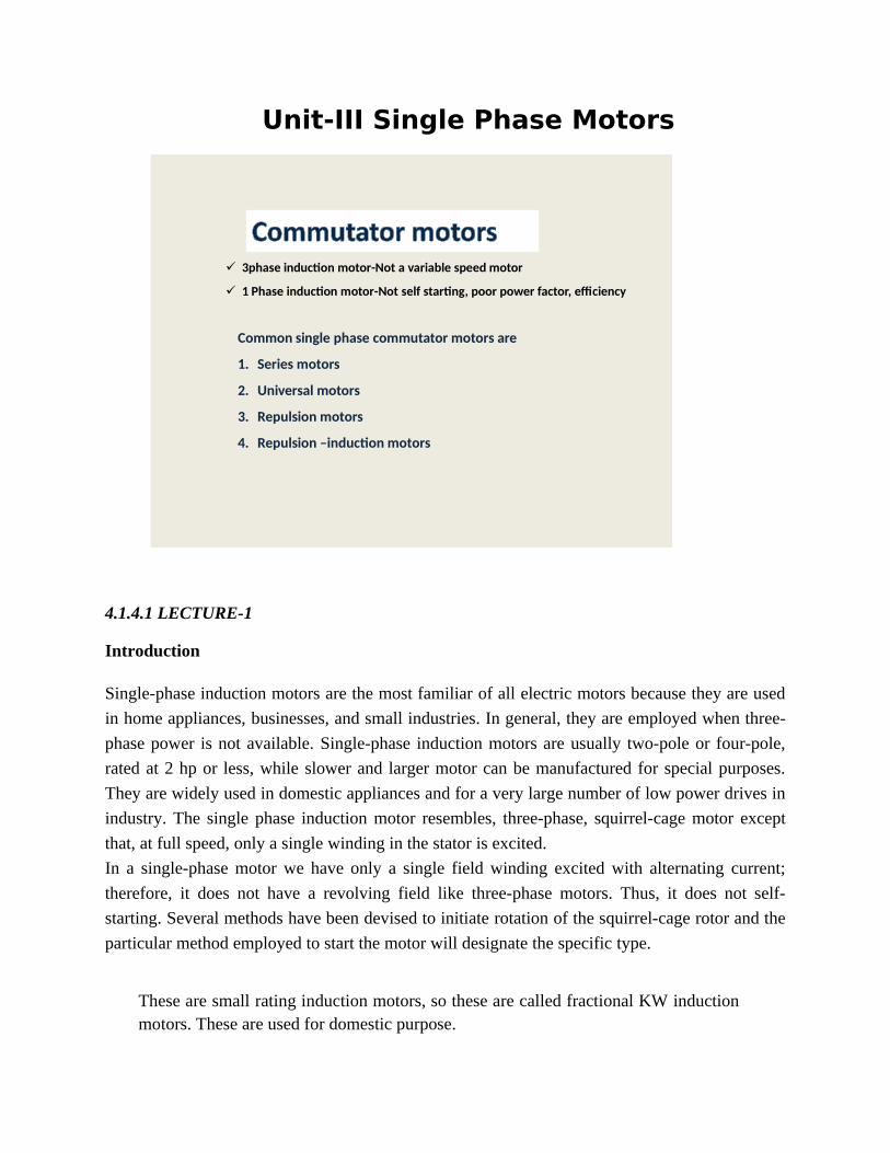
3phase induction motor-Not a variable speed motor
1 Phase induction motor-Not self starting, poor power factor, efficiency
Common single phase commutator motors are
1. Series motors
2. Universal motors
3. Repulsion motors
4. Repulsion –induction motors
4.1.4.1 LECTURE-1
Introduction
Single-phase induction motors are the most familiar of all electric motors because they are used
in home appliances, businesses, and small industries. In general, they are employed when three-
phase power is not available. Single-phase induction motors are usually two-pole or four-pole,
rated at 2 hp or less, while slower and larger motor can be manufactured for special purposes.
They are widely used in domestic appliances and for a very large number of low power drives in
industry. The single phase induction motor resembles, three-phase, squirrel-cage motor except
that, at full speed, only a single winding in the stator is excited.
In a single-phase motor we have only a single field winding excited with alternating current;
therefore, it does not have a revolving field like three-phase motors. Thus, it does not self-
starting. Several methods have been devised to initiate rotation of the squirrel-cage rotor and the
particular method employed to start the motor will designate the specific type.
These are small rating induction motors, so these are called fractional KW inductionmotors. These are used for domestic purpose.
First consider a single phase, single winding induction motor
Here only one single winding is present
If N𝑐𝑜𝑠 ; no. of turns which are placed at an space angle ∅ 𝜃 and i(t)=im 𝑐𝑜𝑠𝜔𝑡 By applying double field theory.
The 1−∅ MMF can be divided two oppositely rotating MMF waves which rotate at synchronousspeeds in opposite directions.
𝐹=𝐹𝑚𝑐𝑜𝑠𝜃𝑐𝑜𝑠𝜔𝑡 = 𝐹𝑚2(𝜃−𝜔𝑡)+𝐹𝑚2𝑐𝑜𝑠(𝜃+𝜔𝑡)
= Ff + Fb
Φf Φb
𝑐𝑜𝑠(𝜃+𝜔𝑡)−𝑏𝑎𝑐𝑘𝑤𝑎𝑟𝑑 𝑟𝑜𝑡𝑎𝑡𝑖𝑛𝑔
𝑐𝑜𝑠(𝜃−𝜔𝑡)−𝑓𝑜𝑟𝑤𝑎𝑟𝑑 𝑟𝑜𝑡𝑎𝑡𝑖𝑛𝑔
Both of these magnetic fields rotate with synchronous speed. Because of two fluxes, here twoslips are present
Forward slip sf =N s−N
N s
=s
Backward slip sb=N s+N
N s
=2−s
Therefore backward slip = 2-s; Slip can be defined with the direction of rotation of rotor.
(2 – s) > > s and sb > >sf .
Slip changes with direction of rotation of rotor. If rotor rotates in anticlockwise direction then sf= 2 – s, andsb=s.
At stand still, Nr = 0, sf = 1 and sb= 1.
∅ f
∅b
(Main field forward flux) (Mainfield bakward flux.)
E2 f E2b
I 2 f I 2b
Two currents are produced in rotor. The direction of these currents can be found by lenz’s
law and these currents produce forward flux and backward flux.
At the time starting Nr=0; initially rotor it is at rest: Forward slip 𝑆𝑓=1; backward slip 𝑆𝑏=2−1=1 Forward speed =𝑁𝑠; Backward speed =𝑁𝑠
In rotor two rotor currents are flowing through rotor bars. Direction of rotor current found
by Lenz’s law.
𝑓𝑙𝑢𝑥 𝑑𝑢𝑒 𝑡𝑜 𝑟𝑜𝑡𝑜𝑟 𝑤𝑖𝑛𝑑𝑖𝑛𝑔- ∅2 f
The direction of I 2 f found by applying the LENZ’s law
Resulting forward flux ∅rf =∅f −∅2 f
Resultant backward flux ∅rb=∅b−∅2 b
Both torques are operating in opposite direction.
T r=T f −T b
T r=0
That’s why we can say that 1−∅, single winding it cannot produce starting torque at thetime of starting is zero.
4.1.4.2 Lecture 2
Construction of single phase induction motor:
Single phase power system is widely used as compared to three phase system for domesticpurpose, commercial purpose and to some extent in industrial purpose. As the single phasesystem is more economical and the power requirement in most of the houses, shops, offices aresmall, which can be easily met by single phase system. The single phase motors are simple inconstruction, cheap in cost, reliable and easy to repair and maintain. Due to all these advantagesthe single phase motor finds its application in vacuum cleaner, fans, washing machine,centrifugal pump, blowers, washing machine, small toys etc. The single phase ac motors arefurther classified as:
1. Single phase induction motors or asynchronous motors.2. Single phase synchronous motors.3. Commutator motors.
This article will provide fundamentals, description and working principle of single phaseinduction motor.
Comparison between Single Phase and Three Phase Induction Motors
1. The electrical power factor of single phase induction motors is low as compared to threephase induction motors.
2. For same size, the single phase induction motors develop about 50% of the output as that ofthree phase induction motors.
3. The starting torque is also low for asynchronous motors / single phase induction motor.
4. The efficiency of single phase induction motors is less as compare it to the three phaseinduction motors.
5. Single phase induction motors are simple, robust, reliable & cheaper for small ratings. Theyare generally available up to 1 KW rating.
6. Single phase induction motors are simple in construction, reliable and economical for smallpower rating as compared to three phase induction motors.
Construction of Single Phase Induction MotorLike any other electrical motor asynchronous motor also have two main parts namely rotor andstator.
Stator: As its name indicates stator is a stationary part of induction motor. A single phase acsupply is given to the stator of single phase induction motor. Rotor: The rotor is a rotating part ofinduction motor. The rotor is connected to the mechanical load through the shaft. The rotor insingle phase induction motor is of squirrel cage rotor type. The construction of single phaseinduction motor is almost similar to the squirrel cage three phase motor except that in case ofasynchronous motor the stator have two windings instead of one as compare to the single statorwinding in three phase induction motor.
Stator of Single Phase Induction MotorThe stator of the single phase induction motor has laminated stamping to reduce eddy currentlosses on its periphery. The slots are provided on its stamping to carry stator or main winding. Inorder to reduce the hysteresis losses, stamping are made up of silicon steel. When the statorwinding is given a single phase ac supply, the magnetic field is produced and the motor rotates ata speed slightly less than the synchronous speed Ns which is given by
Where,f = supply voltage frequency,P = No. of poles of the motor.The construction of the stator of asynchronous motor is similar to that of three phase inductionmotor except there are two dissimilarities in the winding part of the single phase inductionmotor.
1. Firstly the single phase induction motors are mostly provided with concentric coils. As thenumber of turns per coil can be easily adjusted with the help of concentric coils, the mmfdistribution is almost sinusoidal.
2. Except for shaded pole motor, the asynchronous motor has two stator windings namely themain winding and the auxiliary winding. These two windings are placed in spacequadrature with respect to each other.
Rotor of Single Phase Induction MotorThe construction of the rotor of the single phase induction motor is similar to the squirrelcage three-phase induction motor. The rotor is cylindrical in shape and has slots all overits periphery. The slots are not made parallel to each other but are bit skewed as theskewing prevents magnetic locking of stator and rotor teeth and makes the working ofinduction motor more smooth and quieter i.e less noise. The squirrel cage rotor consists
of aluminum, brass or copper bars. These aluminum or copper bars are called rotorconductors and are placed in the slots on the periphery of the rotor. The rotor conductorsare permanently shorted by the copper or aluminum rings called the end rings. In order toprovide mechanical strength these rotor conductor are braced to the end ring and henceform a complete closed circuit resembling like a cage and hence got its name as "squirrelcage induction motor". As the bars are permanently shorted by end rings, the rotorelectrical resistance is very small and it is not possible to add external resistance as thebars are permanently shorted. The absence of slip ring and brushes make the constructionof single phase induction motor very simple and robust.
Working Principle of Single Phase Induction MotorNOTE: We know that for the working of any electrical motor whether its ac or dc motor,we require two fluxes as, the interaction of these two fluxes produced the required torque,which is desired parameter for any motor to rotate. When single phase ac supply is givento the stator winding of single phase induction motor, the alternating current startsflowing through the stator or main winding. This alternating current produces analternating flux called main flux. This main flux also links with the rotor conductors andhence cut the rotor conductors. According to the Faraday’s law of electromagneticinduction, emf gets induced in the rotor. As the rotor circuit is closed one so, the currentstarts flowing in the rotor. This current is called the rotor current. This rotor currentproduces its own flux called rotor flux. Since this flux is produced due to inductionprinciple so, the motor working on this principle got its name as induction motor. Nowthere are two fluxes one is main flux and another is called rotor flux. These two fluxesproduce the desired torque which is required by the motor to rotate.
4.1.4.3
Double revolving field theory
Why Single Phase Induction Motor is not Self Starting?
According to double field revolving theory, any alternating quantity can be resolved intotwo components, each component have magnitude equal to the half of the maximummagnitude of the alternating quantity and both these component rotates in oppositedirection to each other. For example - a flux, φ can be resolved into two components
Each of these components rotates in opposite direction i. e if one φm / 2 is rotating inclockwise direction then the other φm / 2 rotates in anticlockwise direction. When a singlephase ac supply is given to the stator winding of single phase induction motor, it
produces its flux of magnitude, φm. According to the double field revolving theory, thisalternating flux, φm is divided into two components of magnitude φm /2. Each of thesecomponents will rotate in opposite direction, with the synchronous speed, Ns. Let us callthese two components of flux as forward component of flux, φf and backward componentof flux, φb. The resultant of these two component of flux at any instant of time, gives thevalue of instantaneous stator flux at that particular instant.
Now at starting, both the forward and backward components of flux are exactly oppositeto each other. Also both of these components of flux are equal in magnitude. So, theycancel each other and hence the net torque experienced by the rotor at starting is zero. So,the single phase induction motors are not self starting motors.
Methods for Making Single Phase Induction as Self Starting MotorFrom the above topic we can easily conclude that the single phase induction motors arenot self starting because the produced stator flux is alternating in nature and at thestarting the two components of this flux cancel each other and hence there is no nettorque. The solution to this problem is that if the stator flux is made rotating type, ratherthan alternating type, which rotates in one particular direction only. Then the inductionmotor will become self starting. Now for producing this rotating magnetic field werequire two alternating flux, having some phase difference angle between them. Whenthese two fluxes interact with each other they will produce a resultant flux. This resultantflux is rotating in nature and rotates in space in one particular direction only. Once themotor starts running, the additional flux can be removed. The motor will continue to rununder the influence of the main flux only. Depending upon the methods for makingasynchronous motor as Self Starting Motor, there are mainly four types of single phaseinduction motor namely,
1. Split phase induction motor,2. Capacitor start inductor motor,3. Capacitor start capacitor run induction motor,4. Shaded pole induction motor.5. Permanent split capacitor motor or single value capacitor motor.
(1) 1−∅ single winding induction motor is not a self -starting one, due to presence of equalstrength of resultant forward and backward fluxes at the time of starting. As starting torque iszero, rotor cannot accelerate
Rotor under running condition: Once motor is in running condition slips are not equal F f ≠ Fb
So to make 1 - IM, self-starting we should weaken one field and simultaneouslystrengthening another field at the time of starting. So for this purpose wound anotherwinding in the induction motor this is called Auxiliary winding for starting purpose. This type of induction motor can produce torque under running condition due to presence ofunequal strengths of resultant forward and backward fluxes under running condition. In order tomake the induction motor self-starting the resultant forward and backward field should be madeunequal at the time of starting by using some arrangement Starting Methods (i) Small pony motors
(ii) Auxiliary windings
Small pony motors:
Initially the induction motor rotor is coupled with a pony motor and started , and as itreaches to running condition the pony motor is separated and the induction motor operatesat own speed.
Auxiliary winding:
Auxiliary winding is required only for starting purpose
Condition to be satisfied in case of Auxiliary winding:
(1) Auxiliary winding must be placed at 900 electrical to the main field winding. That is they arephysically displaced by 900electrical. (2) The current flowing through those windings must have some phase displacement. If anglebetween main & auxiliary winding current is zero, then no torque is produce.
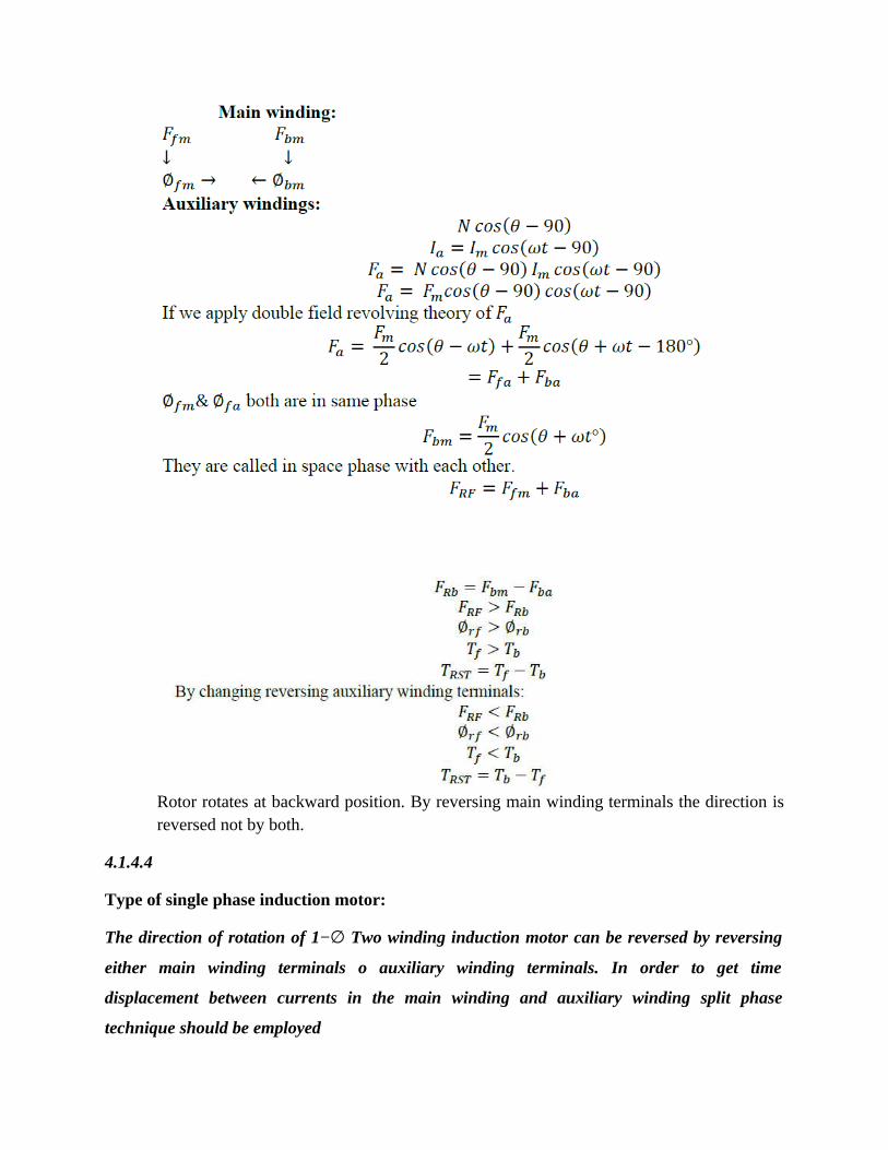
Main winding
im
Auxiliary winding
ia
Rotor rotates at backward position. By reversing main winding terminals the direction isreversed not by both.
4.1.4.4
Type of single phase induction motor:
The direction of rotation of 1−∅ Two winding induction motor can be reversed by reversing
either main winding terminals o auxiliary winding terminals. In order to get time
displacement between currents in the main winding and auxiliary winding split phase
technique should be employed
In order to get time phase displacement between field and auxiliary winding currents, use split
phase techniques.
(1) Resistance split phase induction motor.
(2) Capacitance split phase induction motor.
(a) SPLIT PHASE INDUCTION MOTOR
Split phase induction motor connections.
1. The split phase induction motor is also called as resistance start motor.
2. It is a single cage rotor and its stator has two windings a main winding and a startingwinding.
3. The main field winding and starting winding are displaced 900 in space like thewindings in a 2-phase induction motor.
4. The main winding has very low resistance and high inductive reactance.
5. The current IM in the main winding lags behind the supply voltage by nearly 900.
6. The auxiliary winding has a resistor connected in series with it. It has a high resistance and
low inductive reactance so that the current IA in the auxiliary winding is nearly in phase
with the line voltage.
7. Thus there is a time difference between the currents in the two windings and it is of order
300. This phase difference is enough to produces a rotating magnetic field.
8. Since the currents in the two windings are not equal, the rotating field is not uniform, andthe starting torque is small of order of 1.5 to 2 times the rated running torque.
9. The main and auxiliary windings are connected parallel in during starting.
10. The starting winding is automatically disconnected from the supply when motorreaches speed about 70 to 80 percent of synchronous speed.
11. For motor rated about 100W or more, a centrifugally operated switch is used todisconnect the starting winding.
12. For smaller motors a relay is often used. The relay is connected in series with the mainwinding.
13. At the time of starting, a heavy current flows in the relay coil causing its contact to lose.This brings starting winding into the circuit.
14. As the motor reaches its predetermined speed of the order of 70 to 80 per cent ofsynchronous speed, the current through the relay coil decreases as consequently, the relayopens and disconnects the auxiliary winding from the main supply and the motor thereruns only on the main windings.
15. The torque speed characteristics of this motor is also shows speed n0 at which
centrifugal operates.
APPLICATIONS:
1. Split phase motors are cheap and they are most suitable for easily started loads wherefrequency of starting is limited.
2. The common applications are washing machines, air conditioning fans, food miners,grinders, centrifugal pumps, floor polishers, blowers, small drills, office machinery,dairy machinery etc.
3. Because of low starting torques, they are set down used for drives requiring more than1KW.
4.1.4.5
SINGLE-PHASE INDUCTION MOTORS (Electric Motor)
There are many types of single-phase electric motors. In this section, the discussion will belimited to those types most common to integral-horsepower motor ratings of 1 hp and higher.
In industrial applications, three-phase induction motors should be used wherever possible. Ingeneral, three-phase electric motors have higher efficiency and power factors and are morereliable since they do not have starting switches or capacitors.In those instances in which three-phase electric motors are not available or cannot be usedbecause of the power supply, the following types of single-phase motors are recommended forindustrial and commercial applications: (1) capacitor-start motor, (2) two-value capacitor motor,and (3) permanent split capacitor motor.A brief comparison of single-phase and three-phase induction motor characteristics will providea better understanding of how single-phase motors perform:1. Three-phase motors have locked torque because there is a revolving field in the air gap atstandstill. A single-phase motor has no revolving field at standstill and therefore develops nolocked-rotor torque. Anauxiliary winding is necessary to produce the rotating field required forstarting. In an integral-horsepower single-phase motor, this is part of an RLC network.2. The rotor current and rotor losses are insignificant at no load in a three-phase motor. Single-phase motors have appreciable rotor current and rotor losses at no load.3. For a given breakdown torque, the single-phase motor requires considerably more flux andmore active material than the equivalent three-phase motor.4. A comparison of the losses between single-phase and three-phase motors is shown in Fig.1.11. Note the significantly higher losses in the single-phase motor.The general characteristics of these types of single-phase induction motors are as follows.
Capacitor-Start Motors
1. It has a cage rotor and its stator has two windings namely, the main winding and theauxiliary winding.
2. The two windings are displaced 900 in space. A centrifugal switch is connected and acapacitor cs is connected in series with starting windings.
3. By choosing a capacitor of the proper rating the current IM in the main winding may be
made to lag the current IA in the auxiliary winding by 900.
4. Thus a single phase supply current is split into two phases to be applied to the statorwindings.
5. Thus the windings are displaced 900 electrical and their mmf’s are equal in magnitude
but 900 apart in time phase
6. The motor acts like a balanced two-phase motor.
7. As the motor approaches its rated speed, the auxiliary winding and the starting
capacitor cs are disconnected automatically by the centrifugal switch sc mounted on
the shaft
8. The motor is named because it uses the capacitor only for the purpose of starting.
A capacitor-start motor is a single-phase induction motor with a main winding arranged fordirect connection to the power source and an auxiliary winding connected in series with acapacitor and starting switch for disconnecting the auxiliary winding from the power source afterstarting. Figure 1.12 is a schematic diagram of a capacitor-start motor. The type of startingswitch most commonly used is a centrifugally actuated switch built into the motor. Figure
FIGURE 1.11 Percent loss comparison of single- and three-phase motors.
FIGURE 1.12 Capacitor-start single-phase motor.1.13 illustrates an industrial-quality drip-proof single-phase capacitor-start motor; note thecentrifugally actuated switch mechanism.However, other types of devices such as current-sensitive and voltage-sensitive relays are alsoused as starting switches. More recently, solid-state switches have been developed and used to a
FIGURE 1.13 Capacitor-start single-phase motor. (Courtesy Magnetek, St. Louis, MO.)limited extent. The solid-state switch will be the switch of the future as it is refined and costs arereduced.All the switches are set to stay closed and maintain the auxiliary winding circuit in operationuntil the motor starts and accelerates to approximately 80% of full-load speed. At that speed, theswitch opens, disconnecting the auxiliary winding circuit from the power source.The motor then runs on the main winding as an induction motor. The typical speed-torquecharacteristics for a capacitor-start motor are shown in Fig. 1.14. Note the change in motortorques at the transition point at which the starting switch operates.The typical performance data for integral-horsepower, 1800-rpm, capacitor-start, induction-runmotors are shown in Table 1.6. There will be a substantially wider variation in the values oflocked-rotor torque, breakdown torque, and pull-up torque for these single-phase motors than forcomparable three-phase motors, and the same variation also exists for efficiency and the powerfactor (PF). Note that pull-up torque is a factor in single-phase motors to ensure starting withhigh-inertia or hard-to-start loads. Therefore, it is important to know the characteristics of thespecific capacitor-start motor to make certain it is suitable for the application.
A two-value capacitor motor is a capacitor motor with different values of capacitance for startingand running. Very often, this type of motor is referred to as a capacitor-start, capacitor-runmotor.The change in the value of capacitance from starting to running conditions is automatic by meansof a starting switch, which is the same as that used for the capacitor-start motors. Two capacitorsare provided, a high value of capacitance for starting conditions and a lower value for runningconditions. The starting capacitor is usually an electrolytic type, which provides high capacitanceper unit volume. The running capacitor is usually a metallized polypropylene unit rated forcontinuous operation. Figure 1.15 shows one method of mounting both capacitors on the motor.The schematic diagram for a two-value capacitor motor is shown in Fig. 1.16. As shown, atstarting, both the starting and running
FIGURE 1.14 Speed-torque curve for a capacitor-start motor.capacitors are connected in series with the auxiliary winding. When the starting switch opens, it
disconnects the starting capacitor from the auxiliary winding circuit but leaves the runningcapacitor in series with the auxiliary winding connected to the power source. Thus, both the mainand auxiliary windings are energized when the motor is running and contribute to the motoroutput. A typical
TABLE 1.6 Typical Performance of Capacitor-Start Motors3
hpFull-load performance Torque, lb-ft
rpm A Eff. PF Torque Locked Breakdown Pull-up
1 1725 7.5 71 70 3.0 9.9 7.5 7.6
2 1750 12.5 72 72 6.0 17.5 14.7 11.5
3 1750 17.0 74 79 9,0 23,0 21.0 18,5
5 1745 27.3 78 77 15.0 46.0 32.0 35.0
a Four-pole, 230-V, single-phase motors. Source: Courtesy Magnetek, St. Louis, MO.speed-torque curve for a two-valve capacitor motor is shown in Fig. 1.17.For a given capacitor-start motor, the effect of adding a running capacitor in the auxiliarywinding circuit is as follows:Increased breakdown torque: 5-30% Increased lock-rotor torque: 5-10% Improved full-loadeciency: 2-7 points
FIGURE 1.15 Two-value capacitor, single-phase motor. (Courtesy Magnetek, St. Louis,MO.)
FIGURE 1.16 Two-value capacitor, single-phase motor.Improved full-load power factor: 10-20 points Reduced full-load running current Reducedmagnetic noise Cooler runningThe addition of a running capacitor to a single-phase motor with properly designed windingspermits the running performance to approach the performance of a three-phase motor. Thetypical performance of integral-horsepower, two-value capacitor motors is shown in Table 1.7.Comparison of this performance with the performance shown in Table 1.6 for capacitor-startmotors shows the improvement in both efficiency and the power factor.The optimum performance that can be achieved in a two-value capacitor, single-phase motor is afunction of the economic factors as well as the technical considerations in the design of themotor. To illustrate this, Table 1.8 shows the performance of a single-phase motor with thedesign optimized for various values of running capacitance. The base for the performancecomparison is a capacitor-start, induction-run motor with no running capacitor. Table 1.9 showsthat performance improves with increasing values
FIGURE 1.17 Speed-torque curve for a two-value capacitor motor.of running capacitance and that the motor costs increase as the value of running capacitance isincreased. The payback period in years was calculated on the basis of 4000 hr/yr of operationand an electric power cost of 6^/kWh. Note that the major improvement in motor performance ismade in the initial change from a capacitor-start to a two-value capacitor motor with a relativelylow value of running capacitance. This initial design change also shows the shortest paybackperiod.The determination of the optimum two-value capacitor motor for a specific application requires acomparison of the motor costs and the energy consumptions of all such available motors. It isTABLE 1.7 Typical Performance of Two-Value Capacitor Motors3
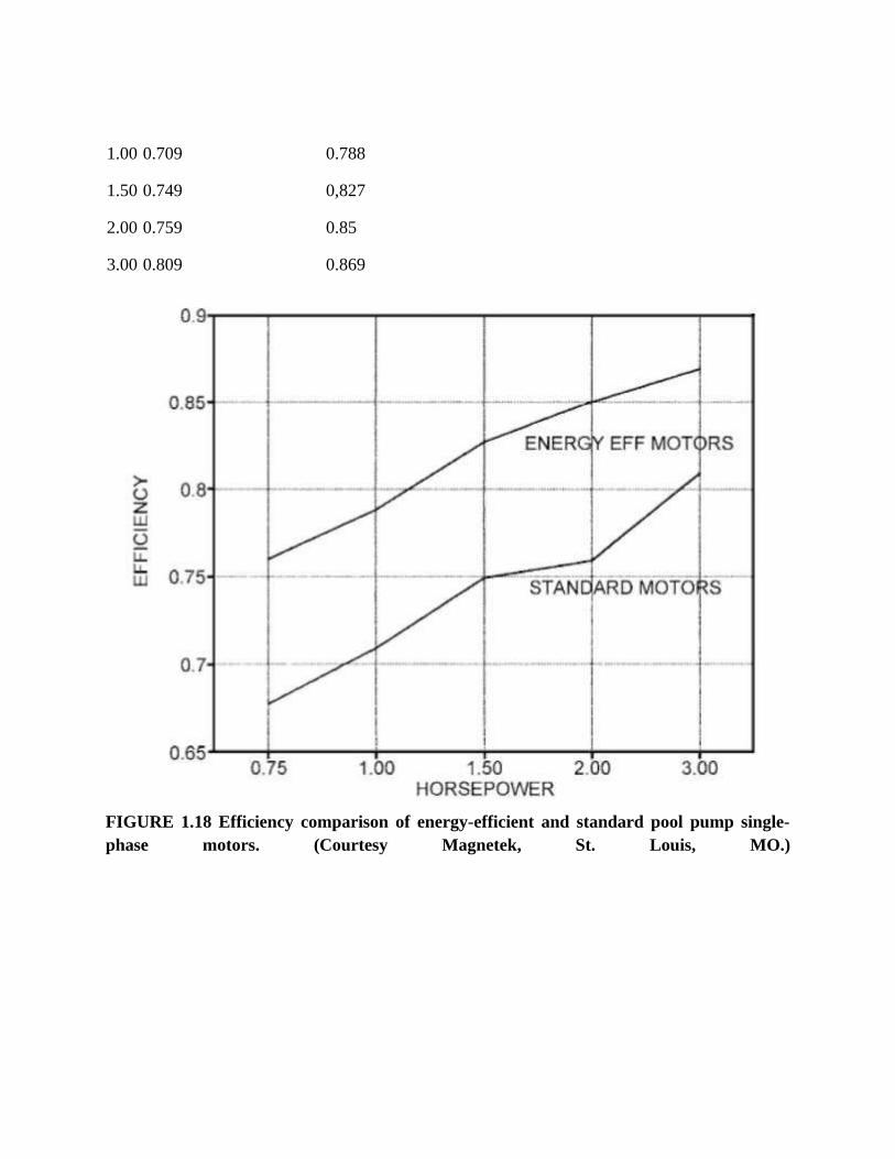
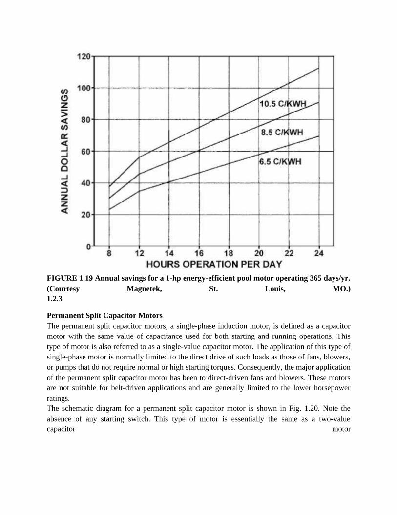
a Four-pole, 230-V, single-phase motors. Source: Courtesy Magnetek, St. Louis, MO.recommended that this comparison be made by a life-cycle cost method or the net present worthmethod (outlined in topic 7).The efficiency improvement and energy savings of a specific product line of pool pump motorswhen the design was changed from capacitor-start motors to two-value capacitor motors areillustrated by Table 1.9 and Figs. 1.18 and 1.19. Based on the same operating criterion usedabove, i.e., 4000-hr/yr operation at power costs of 6^/kWh, the payback period for these motorswas 8-20 months.
TABLE 1.8 Performance Comparison of Capacitor-Start and Two-Value CapacitorMotors
Type of motor
Capacitor start Two-value capacitor
Running capacitor, MFD 0 7.5 15 30 65
Full-load efficiency 70 78 79 81 83
Full-load PF 79 9-1 97 99a 99:l
Input watts reduction, % 0 10.1 11,5 13,3 15
Cost, % 100 130 110 151 196
Approximate payback period — 1.3 1.0 1.8 2.9
a Leading power factor.
TABLE 1.9 Efficiency Comparison: Standard and Energy-Efficient 3600-rpm, Single-Phase Pool MotorshP Standard efficient motors Energy-efficient motors
FIGURE 1.19 Annual savings for a 1-hp energy-efficient pool motor operating 365 days/yr.(Courtesy Magnetek, St. Louis, MO.)1.2.3
Permanent Split Capacitor MotorsThe permanent split capacitor motors, a single-phase induction motor, is defined as a capacitormotor with the same value of capacitance used for both starting and running operations. Thistype of motor is also referred to as a single-value capacitor motor. The application of this type ofsingle-phase motor is normally limited to the direct drive of such loads as those of fans, blowers,or pumps that do not require normal or high starting torques. Consequently, the major applicationof the permanent split capacitor motor has been to direct-driven fans and blowers. These motorsare not suitable for belt-driven applications and are generally limited to the lower horsepowerratings.The schematic diagram for a permanent split capacitor motor is shown in Fig. 1.20. Note theabsence of any starting switch. This type of motor is essentially the same as a two-valuecapacitor motor
FIGURE 1.20 Permanent split capacitor single-phase motooperating on the running connection and will have approximately the same torque characteristics.Since only the running capacitor (which is of relative low value) is connected in series with theauxiliary winding on starting, the starting torque is greatly reduced. The starting torque is only20-30% of full-load torque. A typical speed-torque curve for a permanent split capacitor motor isshown in Fig. 1.21. The running performance of this type of motor in terms of efficiency andpower factor is the same as a two-value capacitor motor. However, because of its low startingtorque, its successful application requires close coordination between the motor manufacturerand the manufacturer of the driven equipment.A special version of the capacitor motor is used for multiple-speed fan drives. This type ofcapacitor motor usually has a tapped main winding and a high-resistance rotor. The high-resistance rotor is used to improve stable speed operation and to increase the starting torque.There are a number of versions and methods of winding motors. The most common design is thetwo-speed motor, which has three windings: the main, intermediate, and auxiliary windings. For230-V power service, a common connection of the windings is called the T connection.Schematic diagrams for two-speed T-connected motors are shown in Figs. 1.22 and 1.23. For
FIGURE 1.21 Speed-torque curve for a permanent split capacitor motor.high-speed operation, the intermediate winding is not connected in the circuit as shown in Fig.1.23, and line voltage is applied to the main winding and to the auxiliary winding and capacitorin series. For low-speed operation, the intermediate winding is connected in series with the mainwinding and with the auxiliary circuit as shown in Fig. 1.23. This connection reduces the voltageapplied across both the main wind ing and the auxiliary circuit, thus reducing the torque
FIGURE 1.22 Permanent split capacitor single-phase motor with a T-type connection andtwo-speed operation.the motor will develop and hence the motor speed to match the load requirements. The amountof speed reduction is a function of the turns ratio between the main and intermediate windingsand the speed-torque characteristics of the driven load. It should be recognized that, with thistype of motor, the speed change is obtained by letting the motor speed slip down to the requiredlow
FIGURE 1.23 Permanent split capacitor single-phase motor with a T-type connection and a
winding arrangement.speed; it is not a multispeed motor with more than one synchronous speed.An example of the speed-torque curves for a tapped-winding capacitor motor is shown in Fig.1.24. The load curve of a typical fan load is superimposed on the motor speed-torque curves toshow the speed reduction obtained on the low-speed connection.
FIGURE 1.24 Speed-torque curves for a permanent split capacitor single-phase motor witha tapped winding.
4.1.4.6
A.C. Series Motor
AC series motors are also known as the modified dc series motor as their construction isvery similar to that of the dc series motor. Before we discuss these modifications, here it is
essential to discuss what is the need and where do we need to do modifications. In order tounderstand this, consider this question. What will happen when we give an ac supply to dcseries motor? Answer to this question is written below:
(a) An ac supply will produce a unidirectional torque because the direction of both thecurrents (i.e. armature current and field current) reverses at the same time.
(b) Due to presence of alternating current, eddy currents are induced in the yoke and fieldcores which results in excessive heating of the yoke and field cores.
(c) Due to the high inductance of the field and the armature circuit, the power factor wouldbecome very low.
(d) There is sparking at the brushes of the dc series motor. So considering above points wecan say that we don’t have good performance of dc series motor on the application of acsupply. Now in order to reduce the eddy currents there is need to laminate the yoke andfield core. This is our first modification to dc series motor. What about power factorhow we can improve power factor? Now the power factor is directly related to reactanceof the field and armature circuit and we can reduce the field winding reactance byreducing the number of turns in the field winding. But there is one problem: on reducingthe number of turns, field mmf will decrease and due to this the air gap flux decrease.The overall result of this is that there is an increase in the speed of the motor butdecrease in the motor torque which is not desired. Now how to overcome from thisproblem? The solution to this problem is the use of compensating winding. On the basisof the usage of compensating winding we have two types of motor and they are writtenbelow:
(a) conductively compensated type of motors
(b) Inductively compensated type of motors.
There are five important characteristics of an ac series motor which are written below:
a) Power factor characteristics b) Speed current characteristics
c) Torque current characteristics d) Torque speed characteristics
e) Power output characteristics
Given below is the circuit diagram of the conductively compensated type of motors. Inthis type of motor, the compensating winding is connected in series with the armaturecircuit.
Inductively Compensated Type of Motors
Given below is the circuit diagram of the inductively compensated type of motors. In thistype of motor, the compensating winding has no interconnection with the armature circuit ofthe motor. In this case, a transformer action will take place as the armature winding will actas primary winding of the transformer and the compensation winding will acts as asecondary winding. The current in the compensating winding will be in phase opposition tothe current in the armature winding.
Given below is the complete schematic diagram of the single phase ac series motor with allthe modifications (i.e. compensating winding and inter pole).
We have already discussed the advantage of having compensating winding. Let us discusswhat is the use of the inter pole?
The main function of the inter poles is to improve the performance of the motor in terms of
higher efficiency and a greater output from the given size of the armature core. We have
taken very high reactive voltage drop of series field as compared to either armature or the
compensating field in order to reduce the series filed inductance. The winding of the inter
pole circuit is connected in parallel with the non inductive shunt as shown in the above
figure.
4.1.4.7
Problems:
a)
The main & Auxiliary winding impedances of 50Hz, capacitor – start 1ø induction motor are..,
Main winding 3+2 .7 j , Auxiliary winding 7+3j. Determine the value of the capacitor to theconnected in series with the auxiliary winding to achieve a phase difference of α =90electrical degrees between the currents of two windings at start.
b) A 200W, 230V, 50 Hz capacitor start motor has the following constant:
Main winding R=4.5Ω, X L=3 . 7Ω
Starting winding R=9.5Ω, X2 l=3 . 5Ω
Find the value of starting capacitance that will result in maximum starting torque.
Sol:
The current ‘Is’ in the starting winding leads the applied voltage ‘V’ by Φs , While the current
‘Im’ in main winding lags V by Φm . The starting torque will be max when phase angle &
between Is & Im is 900.
4.1.5 Test Questions
a) Fill in the blanks type of questions 1. In capacitor motors, the capacitor is connected in ....................... with the starting
winding.2. In ceiling fans generally ...................... motors are used.3. In shaded pole motors the shading coil is normally made of ...................4. The single phase motor suitable for signal devices is ...................... motor.5. If 8 micro F capacitor is used on 200 W capacitor motor, the value of capacitor to be
used on 600 W capacitor will be ..............................6. Any motor may become hot when subjected to ............................7. The starting torque of a capacitor motor is ................................
8. AC series motors of a large size are used in .................................
9. Most of the single phase motors are designed to run in ........................... horse power
range.
10. In capacitor motors, the current is in ........................... with that in the main winding.
1. A capacitor start single phase induction motor will usually have a power factor of
(A) Unity
(B) 0.8 leading
(C) 0.6 leading
(D) 0.6 lagging.
2. A capacitor start, capacitor run single phase induction motor is basically a
(A) ac series motor
(B) dc series motor
(C) 2 phase induction motor
(D) 3 phase induction motor.
3. The starting torque of a capacitor start motor is
(A) Zero
(B) Low
(C) Same as rated torque
(D) More than rated torque.
4. The torque developed by a split phase motor is proportional to
(A) Sine of angle between lm and ls
(B) Cosine of angle between lm and Is
(C) Main winding current, Im
(D) Auxiliary winding current,Is
5. A capacitor start single phase induction motor is switched on the supply with its capacitor
replaced by an inductor of equivalent reactance value. It will
(A) not start
(B) start and run
(C) start and then stall
(D) none of the above
6. The starting capacitor of a single phase motor is
(A) Electrolytic capacitor
(B) Ceramic capacitor
(C) Paper capacitor
(D) None of the above.
7. Which of the following is the most economical method of starting a single phase motor ?
(A) Resistance start method
(B) Inductance start method
(C) Capacitance start method
(D) Split-phase method.
8. The number of turns in the starting winding of a capacitor start motor as compared to that for
split phase motor is
(A) same
(B) more
(C) less
(D) none of the above.
9. In a split phase motor, the ratio of number of turns for starting winding to that for running
winding is
(A) 2.0
(B) more than 1
(C) 1.0
(D) less than 1.
10. A single phase motor generally used for small air compressor is
(A) Capacitor start capacitor runs motor
(B) Reluctance motor
(C) Universal motor
(D) shaded pole motor.
c) True or False questions
1. In case of single phase motors, pulsating flux is set up instead of revolving field as in 3-phase
motors. (T)
2. In split-phase induction motors, two windings are provided. (T)
3. In split-phase induction motors, two windings arc connected in parallel. (T)
4. In split-phase induction motor, both the windings arc connected during starling. (F)
5. A shaded pole motor has laminated salient poles. (T)
6. In shaded pole motors, the winding is provided on poles. (T)
7. A universal motor can be operated on single phase or three phase supply. (F)
8. Normally the direction of rotation of a shaded pole motor cannot be reversed. (T)
9. The starting torque of a single phase motor can be improved by connecting a capacitor in
series with the starting winding. (T)
10. In capacitor motors paper capacitor is used. (T)
4.1.6 Review Questions
d) Objective type of questions(Very short notes)Q1: Is there any relation between the capacitances of two capacitors used in two value capacitormotor?Ans: Starting capacitor has about 10 – 15 times high capacity than the value of runningcapacitor.
Q2: What is size of shaded-pole motor?Ans: These are usually built in small fractional H.P, not exceed 1/4 H.P.
Q3: Why shaded-pole single phase induction motor does not need any special starting techniquelike capacitors and auxiliary winding etc.Ans: Because it is inherently self started motor. The construction of the poles is such that theygive a sweep to the magnetic flux and motor starts rotating.
Q4: How can a universal motor be reversed?Ans: By reversing either the field leads or armature leads but not both.
Q5: What are applications of Stepper motors?Ans: (i) Paper feed motors in typewriters and printers (ii)Positioning of print heads (iii) Pens in XY-plotters (iv) Recording heads in computer disc drives etc.
Q6: Why do we use capacitor-start induction motors in applications requiring high startingtorque in preference to repulsion induction motors?Ans: Capacitors are easily available, cheaper and reliable. Repulsion-induction motors posses aspecial commutator and brushes that require maintenance. Most manufacturers have stoppedmaking them.
Q7: If a single phase motor is driven in any direction by any means, it starts running in thatdirection. Explain why?Ans: Actually a pulsating torque has two components which are equal in magnitude and rotate inopposite direction with synchronous speed at unity slip. Now if the motor rotates in anydirection, the slip decreases and the torque component in this direction increases than the othercomponent and hence motor runs in that direction.
Q8: What is a fractional H.P. motor?
Ans: A small motor having H.P. less than unit is called fractional H.P. motor.
Q9: Which type of rotor is used in single phase motors?Ans: Squirrel cage type
Q10: How the starting winding produce rotation in a single phase resistance start inductionmotor?Ans: The starting winding is highly resistive and the main winding is inductive. So the phasedifference between the two currents becomes nearly 90 degree and hence the motor start as twophase motor. Q11: How the starting winding is made resistive?Ans: It consists of only few turns of smaller diameter.
Q12: How the speed of rotation of a split phase induction motor is reversed?Ans: The terminal connections of the starting windings are reversed with respect to main runningwindings
e) Analytical type questions
1. A 2-winding single-phase motor has the main auxiliary winding currents Im=15 A and
Ia=7.5 A at stand-still. The auxiliary winding current leads the main winding current by α=450
electrical. The two winding are in space quadrature and the effective number of turns areNm=80 and Na=100. Compute the amplitudes of the forward and backward stator mmf waves.Also determine the magnitude of the auxiliary current and its phase angle difference α with themain winding current if only the backward field is to be present.
2. A stepper motor has a step angle of 3˚. Determine (a) resolution (b) number of steps requiredfor the shaft to make 25 revolutions and (c) shaft speed, if the stepping frequency is 3600 pps.
3. A stepper motor has a step angle of 1.8˚. What number should be loaded into the encoder ofits drive system if it is desired to turn on the shaft ten complete revolutions.
4. A 250w, 230V, 50Hz capacitor start motor has the following constants for the main andauxiliary windings: main winding, Zm=(4.5+3.7i)Ω. Auxiliary winding Za=(9.5+3.5i)Ω.Determine the value of the starting capacitor that will place the main and auxiliary windingcurrents in quadrature at starting.
5. A single phase induction motor has stator windings in space quadrature and is supplied with asingle phase voltage of 200V at 50Hz. The standstill impedance of the main winding is(5.2+10.1i) and the auxiliary winding is (19.7+14.2i). Find the value of capacitance to be
inserted in the auxiliary winding for maximum starting torque.
f) Essay type Questions
1. Discuss in detail about the split-phase motors.
2. Discuss about the principle and performance of AC series motor
3. Describe the phase control of 1-phase induction motor
4. Write a short notes on double revolving field theory
5. Discuss about Torque-Speed curve of single-phase induction motor
6. Show that the starting torque of a single phase-phase induction motor is zero
7. What is the principle of operation of universal motor?