Centro Interdipartimentale per la Ricerca Applicata e i Servizi nel Settore della Meccanica Avanzata e della Motoristica Responsabile Prof. Ing. Paolo Tartarini Team Ing. Alberto Muscio, ricercatore Ing. Paolo E. Santangelo, ricercatore dedicato Ing. Orsola Errico, ricercatore dedicato Ing. Marco Cavazzuti, ricercatore dedicato Unità Operativa di Ricerca 1.4 Laboratorio di tecniche antincendio per l’industria meccanica
Transcript
Centro Interdipartimentale
per la Ricerca Applicata e i Servizi
nel Settore della Meccanica Avanzata e della Motoristica
Responsabile
Prof. Ing. Paolo Tartarini
Team
Ing. Alberto Muscio, ricercatore Ing. Paolo E. Santangelo, ricercatore dedicato
Ing. Orsola Errico, ricercatore dedicato
Ing. Marco Cavazzuti, ricercatore dedicato
Unità Operativa di Ricerca 1.4
Laboratorio di tecniche antincendio
per l’industria meccanica
FIRE PROTECTION
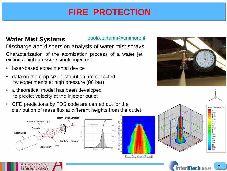
Water Mist Systems
Discharge and dispersion analysis of water mist sprays
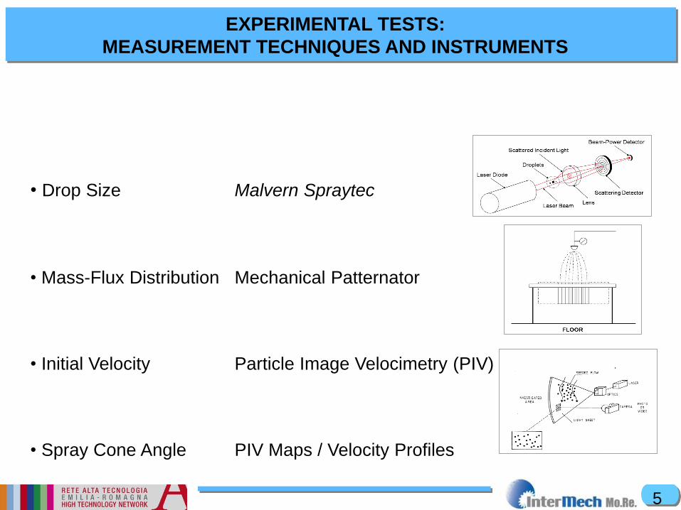
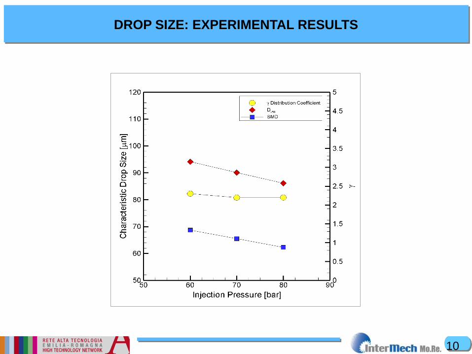
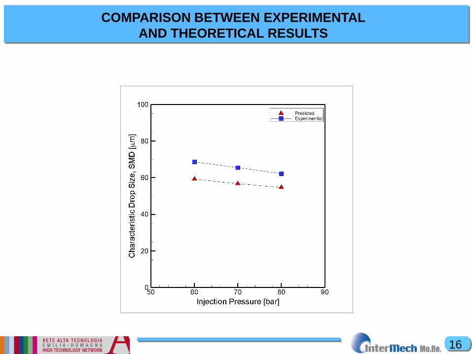
Characterization of the atomization process of a water jet exiting a high-pressure single injector :
• laser-based experimental device
• data on the drop size distribution are collected by experiments at high pressure (80 bar)
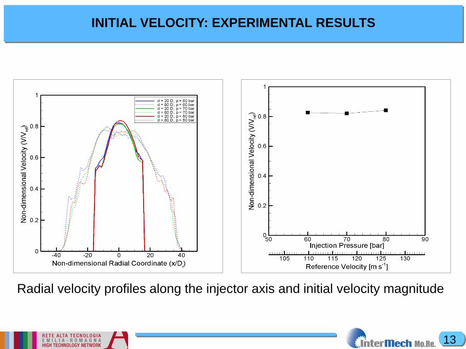
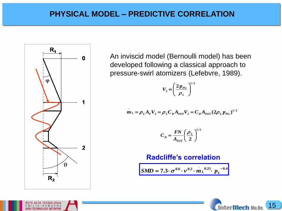
• a theoretical model has been developed
to predict velocity at the injector outlet
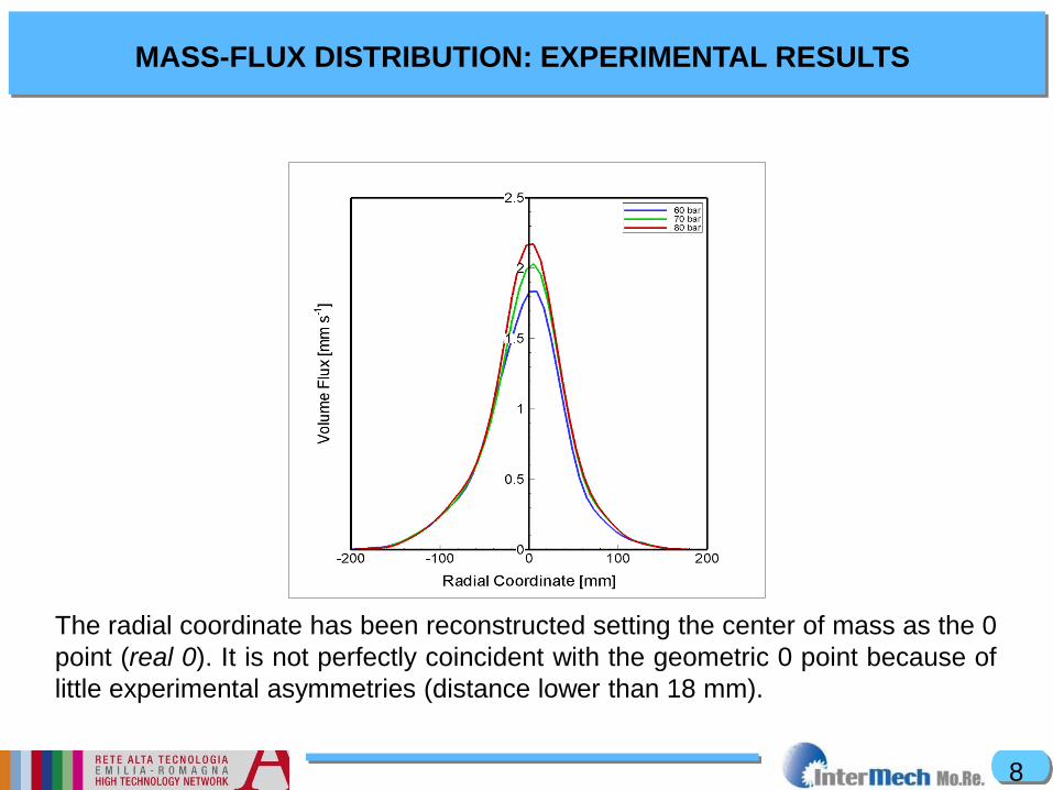
• CFD predictions by FDS code are carried out for the
distribution of mass flux at different heights from the outlet