13/09/2012 Unit.2 Voltage sag 1 D.Maharajan D.Maharajan Ph.D Ph.D Assistant Professor Assistant Professor Department of Electrical and Electronics Department of Electrical and Electronics Engg Engg ., ., SRM University, SRM University, Chennai Chennai - - 203 203 Unit.2 Unit.2 - - Voltage Sag Voltage Sag
Transcript
13/09/2012 Unit.2 Voltage sag 1
D.MaharajanD.Maharajan Ph.DPh.D
Assistant Professor Assistant Professor
Department of Electrical and Electronics Department of Electrical and Electronics EnggEngg.,.,
SRM University,SRM University,
ChennaiChennai--203203
Unit.2Unit.2--Voltage SagVoltage Sag
13/09/2012 Unit.2 Voltage sag 2
Unit-2
-Voltage Sag Mitigation Using
Dynamic Voltage Restorer
(DVR)
13/09/2012 Unit.2 Voltage sag 3
Voltage Reduction Std., IEEE1159-1995E
ve
nt
Ma
gn
itu
de
Voltage sag is defined as a sudden reduction of supply (rms) voltage down
from 90% to 10% of nominal. According to the standard, a typical duration
of sag is l0 ms to 1 minute.
13/09/2012 Unit.2 Voltage sag 4
Possible mitigation methods• Four locations
– 1,2 cheap not available in market
– 4 costly
– 3 widely used
13/09/2012 Unit.2 Voltage sag 5
load conditioning- Customer
• The solution to the power quality can be done
from customer side or from utility side; first
approach is called load conditioning.
• which ensures that the equipment is less
sensitive to power disturbances, allowing the
operation even under significant voltage
distortion.
13/09/2012 Unit.2 Voltage sag 6
Line conditioning-Utility
• The other solution is to install line
conditioning systems that suppress or
counteract the power system disturbances.
13/09/2012 Unit.2 Voltage sag 7
Dynamic voltage Restorer(DVR)static series
compensator with transformer injection
• Series compensation devices
– Protects against
• Sags
• Swells
• unbalance and
• Distortion
Generates or absorbs Reactive power
Response time less
13/09/2012 Unit.2 Voltage sag 8
• Currently they are based on PWM converters and connect to low and medium voltage distribution system in shunt or in series.
• Some of the effective and economic measures can be identified as following
1. Lightning and surge Arresters
2. Thyristor Based Static Switches
3. Energy Storage Systems
4. Electronic tap changing transformer
5. Harmonic filter
13/09/2012 Unit.2 Voltage sag 9
DVR-Introduction
• The DVR is a powerful controller that is commonly used for voltage sags and swells mitigation
• The series voltage controller is connected in series with the protected load.
• It is connected via coupling transformer in series to the ac system.
• The energy storage can be different depending on the needs of compensation
13/09/2012 Unit.2 Voltage sag 10
DVR-Introduction
• DVRs are a class of custom power devices for
providing reliable distribution power quality.
• Series injection of voltage boost technology
using solid state switches for compensating
voltage sags and swells.
• The DVR applications are mainly for sensitive
loads that may be drastically affected by
fluctuations in the system voltage.
13/09/2012 Unit.2 Voltage sag 11
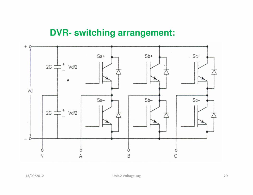
DVR Main components
• 3 phase Voltage Source Converter (VSC)
• coupling transformer
• Passive filter
• Energy storage
• A control system to regulate the output
voltage of VSC
13/09/2012 Unit.2 Voltage sag 12
Main Stages of DVR control system
–detection of the start and finish of
the sag
–voltage reference generation
–injection voltage generation
–protection of sensitive load.
13/09/2012 Unit.2 Voltage sag 13
DVR in Distribution system
13/09/2012 Unit.2 Voltage sag 14
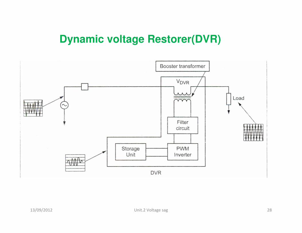
DVR-Principle of operation
• To inject an appropriate voltage in series with
the supply through injection transformer
whenever voltage sag or voltage swell is
detected.
13/09/2012 Unit.2 Voltage sag 15
• The system impedance ZTH depends on the
fault level of the load bus. When the system
voltage (VTH ) drops, the DVR injects a series
voltage VDVR through the injection transformer
so that the desired load voltage magnitude VL
can be maintained.
13/09/2012 Unit.2 Voltage sag 16
Schematic Diagram of DVR
13/09/2012 Unit.2 Voltage sag 17
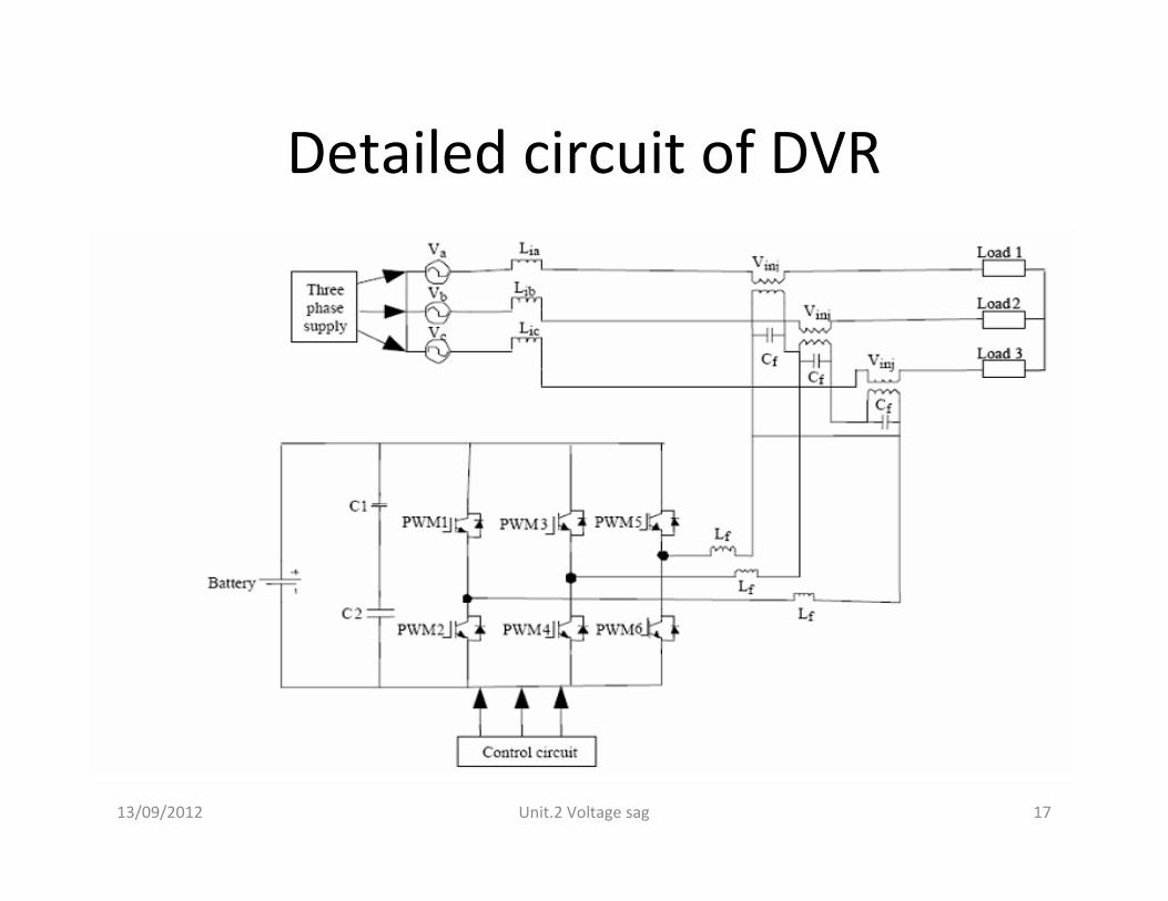
Detailed circuit of DVR
13/09/2012 Unit.2 Voltage sag 18
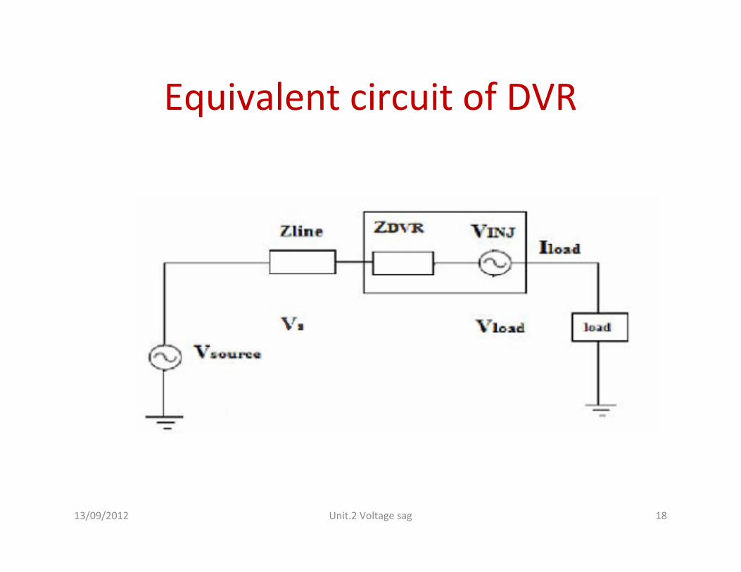
Equivalent circuit of DVR
13/09/2012 Unit.2 Voltage sag 19
Injected voltage by DVR
From the Equivalent circuit, the series injected
voltage of the DVR can be written as
VDVR = VL + ZTHIL –VTH
Where,
VL is the desired load voltage magnitude.
ZTH is the load impedance.
I L is the load current.
VTH is the system voltage during fault condition.
The load current IL is given by IL = (PL + jQL)/VL
13/09/2012 Unit.2 Voltage sag 20
Injected power by DVR
13/09/2012 Unit.2 Voltage sag 21
Operating Modes of the DVR
Any differential voltages caused by transient disturbances in the ac
feeder will be compensated by an equivalent voltage generated by the
converter and injected on the medium voltage level through the booster
transformer.
The operating modes of the DVR are :
1. Protection mode
2. Standby mode
3. Injection/Boost mode
13/09/2012 Unit.2 Voltage sag 22
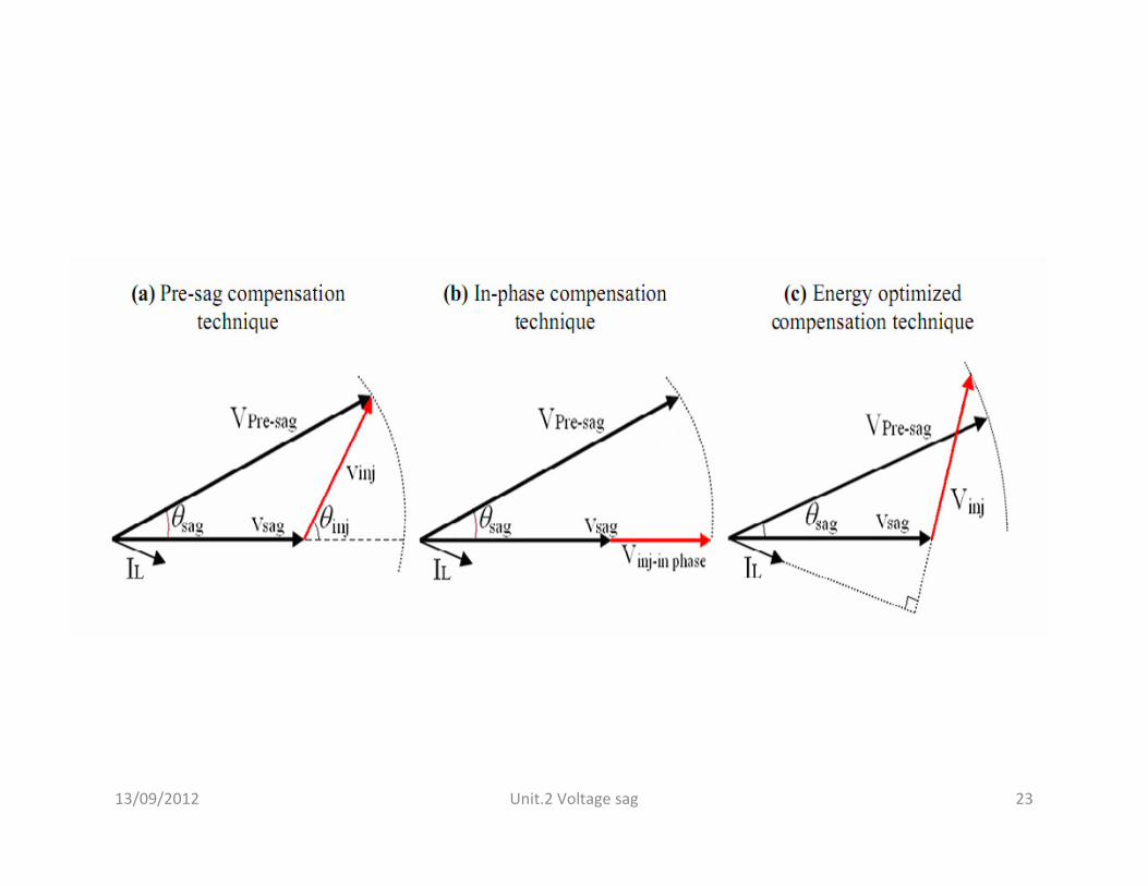
Voltage Injection Methods of the DVR
• Voltage injection methods by means of a DVR depend upon the
limiting factors:
– DVR power ratings,
– various conditions of load,
– different types of voltage sags and swells. • Sensitive towards phase angle jump, change in magnitude .
• Therefore the control strategies depend upon the type of load
characteristics.
• There are four different methods of DVR voltage injection which
are:
1. Pre-sag compensation method
2. In-phase compensation method
3. In-phase advanced compensation method
4. Voltage tolerance method with minimum energy injection
13/09/2012 Unit.2 Voltage sag 23
13/09/2012 Unit.2 Voltage sag 24
Voltage source converter (VSC)
• it is a power electronic device, which can generate a three-
phase ac output voltage is controllable in phase and
magnitude .
• These voltages are injected into the AC distribution system in
order to maintain the load voltage at the desired voltage
reference.
• The VSC is completely replacing the voltage or to inject the
'missing voltage'. The 'missing voltage' is the difference
between the nominal voltage and the actual voltage.
• The converter is using some kind of energy storage, which will
supply the converter with a dc voltage .
13/09/2012 Unit.2 Voltage sag 25
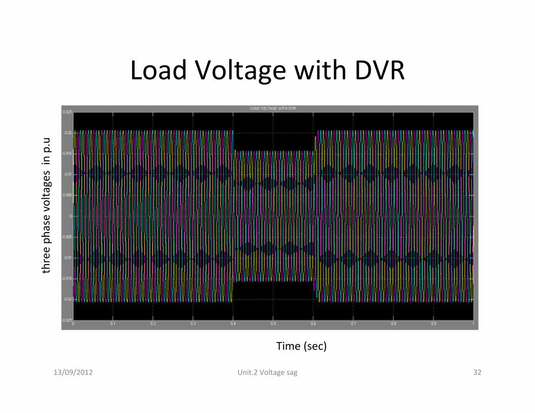
SINUSOIDAL PWM BASED CONTROL
• The aim of the control scheme is to maintain constant voltage magnitude at the point where a sensitive load is connected, under system disturbance.
• The control system only measures the rms voltage at the load point i.e., no reactive power measurements are required.
• The VSC switching strategy is based on sinusoidal PWM technique which offers simplicity and good response.
13/09/2012 Unit.2 Voltage sag 26
• The PI controller identifies the error signal and generates the required angle to drive the error to zero, i.e., the load rms voltage is brought back to the reference voltage.
• In the PWM generator, the sinusoidal signal Vcontrol is compared against a triangular signal (carrier) in order to generate the switching signals for the VSC valves .
• The main parameters of the sinusoidal PWM scheme are the amplitude modulation index Ma of signal control and the frequency modulation index Mf of the triangular signal.
• The amplitude index Ma=(Vcontrol/Vtri) is kept fixed at 1 pu.