UNITED ST ATES DEPARTMENT OF THE INTERIOR BUREAU OF RECLAMATION . DESIGN, ASSEMBLY AND USE OF A · PORTABLE VANE SHEAR TESTER Hydraulic Laboratory Report No. Hyd-434 DIVISION OF ENGINEERING LABO RA TORIES COMMISSIONER'S OFFICE DENVER, COLORADO June 21, 1957
Transcript
UNITED ST ATES DEPARTMENT OF THE INTERIOR
BUREAU OF RECLAMATION
. DESIGN, ASSEMBLY AND USE OF A
· PORTABLE VANE SHEAR TESTER
Hydraulic Laboratory Report No. Hyd-434
DIVISION OF ENGINEERING LABO RA TORIES
COMMISSIONER'S OFFICE DENVER, COLORADO
June 21, 1957
CONTENTS
Summary .................... . Irltroduction .................. . Design~ Assembly and Use of the Vane Shear Tester. Analysis of Loads on Vane. Calibration Conclusions
...
Vane Shear Tester Details Vane Shear Tester ...... . Dial Gage Reading vs Torque Torque vs Shear Stress 4- by 8-inch Vane Torque Ring and Hole Resulting from Shear Test . .. ~ ............................................... .
Laboratory Report No. Hyd-434 Compiled by: P. F. Enger and
T. J. Rhone Checked by: E. J. Carlson Reviewed by: C. W. Thomas
June 21 1 1957 Submitted by: H. M. Martin
DESIGN, ASSEMBLY AND USE OF A PORTABLE VANE SHEAR
TESTER LOWER-COST CANAL LINING PROGRAM
SUMMARY
A study under the Lower-cost Canal Lining Program to determine the relationship between erosion of earth materials in earth lined and unlined canals 1 and the hydraulic tractive forces causing erosion1
is underway by the Hydraulic and Earth Laboratories. Various soils properties are being correlated with hydraulic conditions occuring in canals to improve our methods of design. One soil property that is determined is the in-place resistance to shear near the soil surface. To determine the maximum sheer stress an earth material near the surface can withstand when in place in a canal and in a saturated condition 1
a portable vane shear tester was designed and constructed. Using this instrument1 a simple and inexpensive test in the field can be made by on,e man,
INTRODUCTION
To aid in the erosion-tractive force studies under the Lowercost Canal Lining Prog!'.am1 it was desired to determine the in-place shear strengths of saturated soils near the surface in canal bottoms and banks. A vane shear testing apparatus* presently in use in the Earth Laboratory was developed principally for foundation investigations. The instrument is equipped for testing at various depths under a wide variety of conditions. Accurate shear measurements are made by controlling the rate of testing and providing a complete stress versus rotation record. The primary concern in the erosion and tractive force study is to obtain the shear resistance of the earth canal lining when
*Description and procedure available in Earth Laboratory. Gibbs,. H. J. 1 "An Apparatus and Method of Vane Shear Test
ing of Soil1 "Symposium In-place Shear Testing of Foundations by the Vane Method1 American Society for Testing Materials1 Publication STP-193.
Sam Peng
Sticky Note
None set by Sam Peng
Sam Peng
Sticky Note
MigrationNone set by Sam Peng
Sam Peng
Sticky Note
Unmarked set by Sam Peng
water is flowing in the canal. To accomplish this it is necessary for one man to be able to obtain numerous, quickly made shear measurements. It would be unhandy to use the Earth Laboratory instrument in its pres~nt form to obtain these measurements because of its regulating equipment. For this reason a smaller, simplified vane shear tester, patterned after the Earth Laboratory instrument, was designed and constructed. By eliminating most of the regulating equipment, precise measuring devices and other features necessary for foundation investigations and testing at varying depths, the vane shear tester was made portable, comparatively light and easily operated by one man.
I
The design, assembly and operation of the small portable vane shear tester is described in this report.
DESIGN, ASSEMBLY AND USE OF THE VANE SHEAR TESTER
As shown by Figures 1 and 2, the instru~ent consist_s of a 2-foot-long torque handle, a 5-inch-diameter torque ring machined from a high yield-point steel, a dial strain gage, several 4-foot-long sections of !-inch-diameter extension rods, a soil surface plate, and 3 sets of vanes. The sizes of the 3 vanes are: 2 inches in diameter by 4 inches high; 3 inches in diameter by 4 inches high; and 4 inches in diameter by 8 inches high. While vanes are usually designed with a diameter equal to one-half their length, the 3-inch by 4-inch vane was designed to fur-
- nish a vane with a shear stress range between those of the other two vanes, and to concentrate testing near the soil surface. The torque ring has a 3/8-inch-wide segment removed so that when a torque is applied the ring can deflect. The amount of deflection is measured by the dial strain gage mounted on the ring.
The instrument is assembled in the following sequence. see Figures 1 and 2:
(1) A vane of the desired size is selected and attached to the bottom of a section of the 1-inch extension rod.
(2) The soil surface plate is fastened in the recess just above the vane.
(3) The necessary number of additional extension rods are_ attached.
(4) The torque ring and dial gage assembly are attached to the top of the rods.
(5) The torque handle is attached.
2
Sam Peng
Sticky Note
None set by Sam Peng
Sam Peng
Sticky Note
MigrationNone set by Sam Peng
Sam Peng
Sticky Note
Unmarked set by Sam Peng
In use, the instrument is placed perpendicular to the surface of the soil to be tested and the vane. is gently pushed into the material. If necessary, the soil surface plate may be used as a foot support to help push the vane into the soil. surface. A zero reading of the dial gage is recorded, and a torque is slowly and steadily applied to the torque ring by twisting the 2-foot-long torque handle mounted on top of the ring. The operator should make the rate of rotation slow since the recommended rate of rotation for the Earth Laboratory instrument is 0. 1 degree per second. Although speed control is considered important, it was necessarily eliminated in the smaller instrument to adapt it for this study. The torque is transferred through the split ring into the ex-
. tension rod fastened to the bottom of the ring. The torque in the rod causes the vanes fastened to the lower end of the rod to turn. The turning of the vanes is resisted in shear by a cylindrical area of earth equal to· the periphery of the vanes plus the circular area covered by the bottom of the vanes.
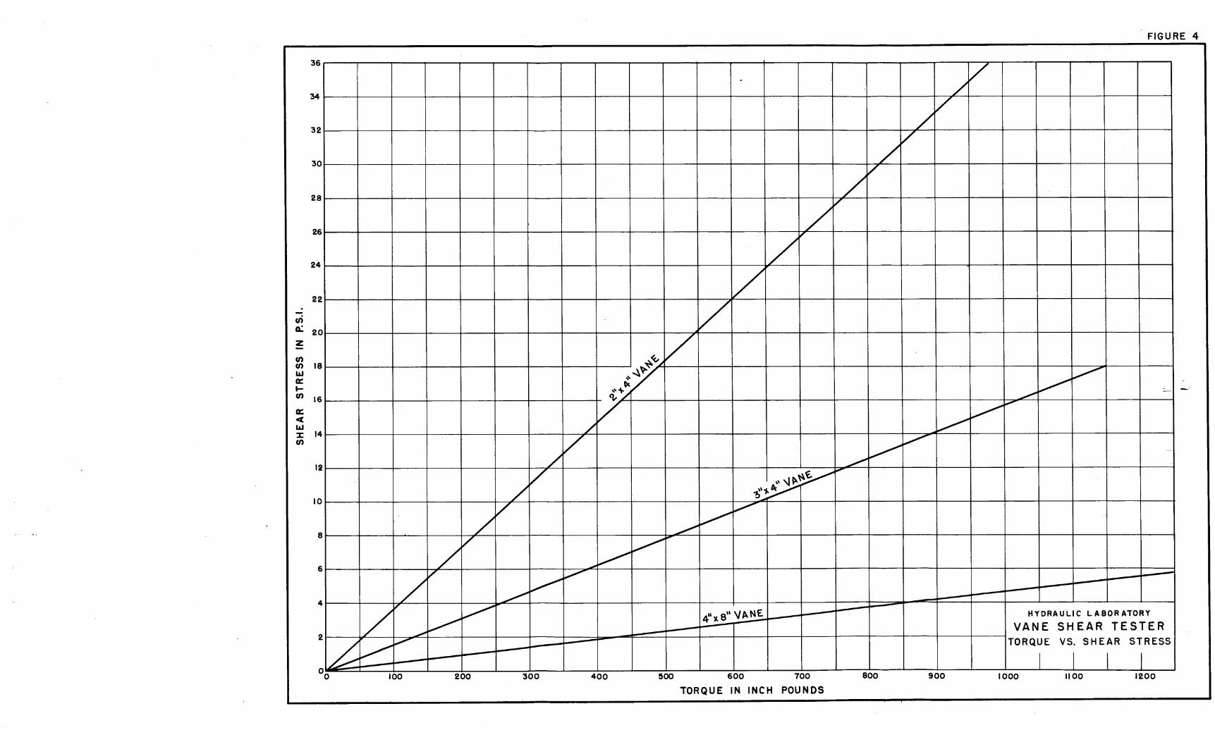
The torque is applied until the dial gage reading reaches a · maximum and backs off. The maximum reading is recorded and the difference between the zero· reading and the maximum is a measure of the applied torque. The split ring was calibrated to determine the relationship between applied torque and dial gage deflection reading. This relationship is shown by the graph on Figure 3. The torque applied to the instruJ::!lent at the time of maximum shear stress is deter-. mined from· the maximum dial gage reading and the curve on Figure 3. The shear stress is then determined from Figure 4 using the proper curve for the vane size used.
Figure 5 shows the torque ring, the 4-inch by 8-inch vane, and a test hole that resulted from a shear test performed on a saturated loess material. Note the smooth sides of the hole and the corresponding circular soil core clinging to the va·nes.
ANALYSIS OF LOADS ON VANE
The vanes are pushed into the soil until the surface plate is flush with the soil surface. Shearing resistance is developed on the cylindrical surface described by the vertical edges of the vanes and on the circular area described by the bottom edges. It is assumed that the shearing stress is uniform over the surface of the cylinder and the bottom circular area. Friction is insignificant and is neglected. A short computation of the total resisting moment follows:
3
Sam Peng
Sticky Note
None set by Sam Peng
Sam Peng
Sticky Note
MigrationNone set by Sam Peng
Sam Peng
Sticky Note
Unmarked set by Sam Peng
Sam Peng
Sticky Note
None set by Sam Peng
Sam Peng
Sticky Note
MigrationNone set by Sam Peng
Sam Peng
Sticky Note
Unmarked set by Sam Peng
T~ is:
where
The total resisting moment developed by the cylindrical surface
2 T' = 277'r HSs C
r = radius of the cylindrical surface described by the vanes
H = height of the vanes Ss = the unit shearing stress over the· entire surface
The total resisting moment developed by the circular bottom area T~ is:
T~ = !1Tr3ss 3
The total resisting moment Tc = T' + T" or T = 277'r 2Ss(H + r.) . c c
C :f
CALIBRATION
The instrument was calibrated by applying a known torque to the vanes and recording the dial gage reading. The plotted average of 12 runs is shown in Figure 3. Calibration results indicated a maximum of 10 percent deviation from the highest to the lowest dial gage reading at a given known torque.
To establish the stress at which the soil fails in shear, the torque required to turn the vanes is first obtained from Figure 3. The torque is then used with Figure 4, which relates the torque to the shear stress for each of the three vanes.
CONCLUSIONS
The relationship between shear resistance of soils in earth canals and their resistance to erosion due to hydraulic tractive forces is one correlation being used in a study under the Lower-cost Canal Lining Program to improve methods of design of earth canals. Using a portable vane shear tester, Figure 2, designed for this purpose, a simple and inexpensive field test can be made to determine the shear resistance of soils, in place, and in a saturated condition. The test can be performed by one man and does not require the extraction of earth samples from the canal. ·
4
Sam Peng
Sticky Note
None set by Sam Peng
Sam Peng
Sticky Note
MigrationNone set by Sam Peng
Sam Peng
Sticky Note
Unmarked set by Sam Peng
Sam Peng
Sticky Note
None set by Sam Peng
Sam Peng
Sticky Note
MigrationNone set by Sam Peng
Sam Peng
Sticky Note
Unmarked set by Sam Peng
The vane shear tester described in this report was designed for the special purpose of testing for the erosion and tractive force study in earth canals. It is not considered adaptable to foundation testing where greater control and more complete information are de-sired, or to subsurface investigations at varying depths. ·