UNITED STATES ARMY AVIATION CENTER FORT RUCKER, ALABAMA May 2008 STUDENT HANDOUT (LOT 11) TITLE: AH-64D AUXILIARY POWER UNIT FILE NUMBER: 011-1013 Proponent For This Student Handout Is: United States Army Aviation School Fort Rucker, AL 36362 FOREIGN DISCLOSURE STATEMENT: This product/publication has been reviewed by the product developers in coordination with the Ft. Rucker foreign disclosure authority. This product is releasable to students from foreign countries on a case-by-case basis. Distribution authorized to U.S. Government agencies and their contractors; Critical Technology August 10, 1999. Other requests for this document will be referred to Department of the Army, PEO Aviation — Apache, SFAE-AV-AAH-LI, Apache Attack Helicopter, Bldg. 5681, Suite 174, Redstone Arsenal, AL 35898. COMM (256) 313-4068 or DNS 897-4068.
Transcript
UNITED STATES ARMY AVIATION CENTER
FORT RUCKER, ALABAMA
May 2008
STUDENT HANDOUT
(LOT 11)
TITLE: AH-64D AUXILIARY POWER UNIT
FILE NUMBER: 011-1013
Proponent For This Student Handout Is: United States Army Aviation School
Fort Rucker, AL 36362 FOREIGN DISCLOSURE STATEMENT: This product/publication has been reviewed by the product developers in coordination with the Ft. Rucker foreign disclosure authority. This product is releasable to students from foreign countries on a case-by-case basis.
Distribution authorized to U.S. Government agencies and their contractors; Critical Technology August 10, 1999. Other requests for this document will be referred to Department of the Army, PEO Aviation — Apache, SFAE-AV-AAH-LI, Apache Attack Helicopter, Bldg. 5681, Suite 174, Redstone Arsenal, AL 35898. COMM (256) 313-4068 or DNS 897-4068.
PFN 011–1013 May 2008
D-2
TERMINAL LEARNING OBJECTIVE:
At the completion of this lesson you will:
ACTION: Troubleshoot the AH-64D Auxiliary Power Unit (APU).
CONDITIONS: Given an AH-64D helicopter, TM 1-1520-251-10, TM 1-1520-251-CL, and TM 1-1520-251-MTF, and a Soldiers’ Portable On-Line Repair Tool (SPORT) with TM 1-1520-LONGBOW/APACHE Interactive Electronic Technical Manual (IETM) software.
STANDARD: In accordance with TM 1-1520-251-10, TM 1-1520-251-CL, TM 1-1520-251-MTF, and TM 1-1520-LONGBOW/APACHE IETM.
PFN 011–1013 May 2008
D-3
INTRODUCTION:
In order for you to properly perform your mission as a maintenance manager/maintenance test pilot, one of your primary responsibilities will be to maintain the AH-64D in a mission-ready status. To ensure that your unit is ready to conduct combat operations, you must have the knowledge to troubleshoot, diagnose malfunctions, and prescribe corrective actions for the AH-64D Auxiliary Power Unit.
PFN 011–1013 May 2008
D-4
A. Enabling Learning Objective 1
After this lesson, you will:
ACTION: Identify the characteristics of the AH-64D APU.
CONDITIONS: Given a written test utilizing the IETM without the use of student notes or references.
STANDARD: In accordance with TM 1-1520-251-10 and TM 1-1520-LONGBOW/APACHE IETM.
1. Learning Step/Activity 1
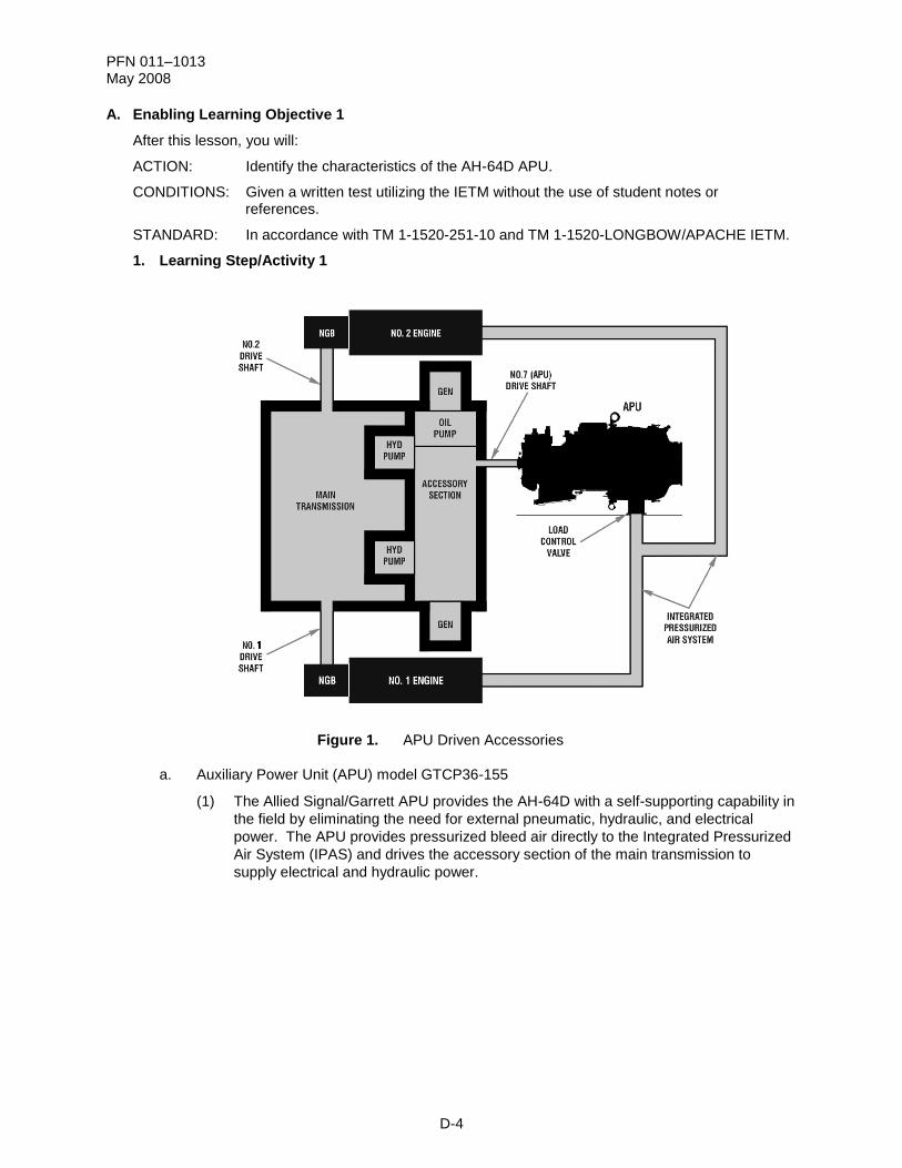
Figure 1. APU Driven Accessories
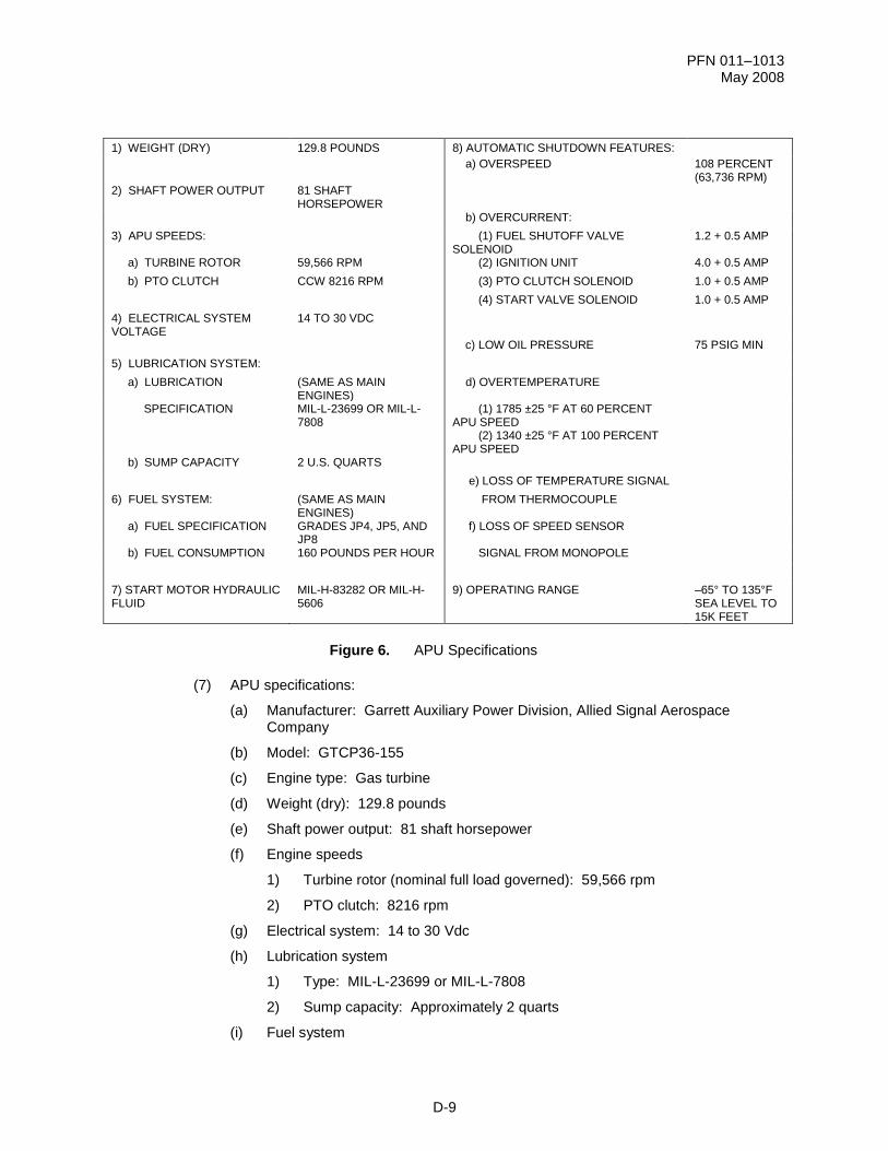
a. Auxiliary Power Unit (APU) model GTCP36-155
(1) The Allied Signal/Garrett APU provides the AH-64D with a self-supporting capability in
the field by eliminating the need for external pneumatic, hydraulic, and electrical
power. The APU provides pressurized bleed air directly to the Integrated Pressurized
Air System (IPAS) and drives the accessory section of the main transmission to
supply electrical and hydraulic power.
PFN 011–1013 May 2008
D-5
Figure 2. AH-64D Auxiliary Power Unit
(2) The APU is a self-contained, fully automatic, constant speed, gas turbine engine
requiring only DC power, fuel, and input signals from the helicopter for operation.
Electromechanical controls control and support APU starts, acceleration, operation,
and shutdown.
AH-64D AUXILIARY POWER UNIT
PFN 011–1013 May 2008
D-6
Figure 3. APU Location
(3) The APU is located under a five-piece Kevlar®
and epoxy enclosure on the right side
of the aft equipment bay, aft of the main rotor support structure (in the catwalk).
(4) An APU Electronic Control Unit (ECU) provides operational sequencing of control for
automatic starting, Power Takeoff (PTO) clutch operation, normal operation, and APU
protection. The APU ECU is mounted on top of the APU enclosure.
PFN 011–1013 May 2008
D-7
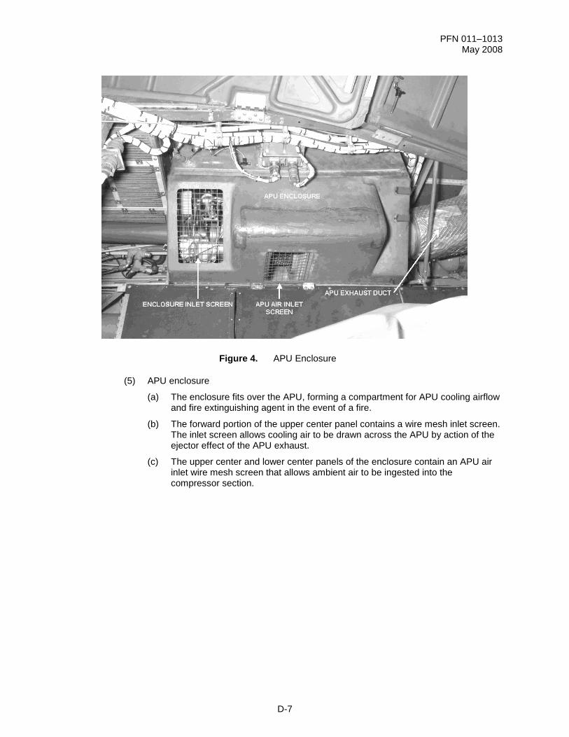
Figure 4. APU Enclosure
(5) APU enclosure
(a) The enclosure fits over the APU, forming a compartment for APU cooling airflow and fire extinguishing agent in the event of a fire.
(b) The forward portion of the upper center panel contains a wire mesh inlet screen. The inlet screen allows cooling air to be drawn across the APU by action of the ejector effect of the APU exhaust.
(c) The upper center and lower center panels of the enclosure contain an APU air inlet wire mesh screen that allows ambient air to be ingested into the compressor section.
PFN 011–1013 May 2008
D-8
Figure 5. APU Mounts
(6) APU mounts
(a) The APU is attached to the equipment bay deck by three mounts that are the sole supports for the APU. The APU mounts are as follows:
ACTION: Identify the characteristics of the APU major sections.
CONDITIONS: Given a written test utilizing the IETM without the use of student notes or references.
STANDARD: In accordance with TM 1-1520-251-10 and TM 1-1520-LONGBOW/APACHE IETM.
1. Learning Step/Activity 1
Identify the characteristics of the APU power section.
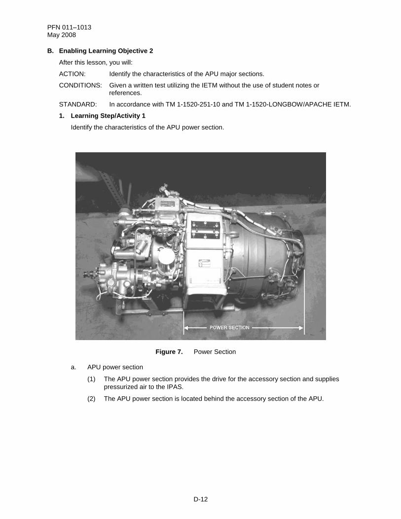
Figure 7. Power Section
a. APU power section
(1) The APU power section provides the drive for the accessory section and supplies
pressurized air to the IPAS.
(2) The APU power section is located behind the accessory section of the APU.
PFN 011–1013 May 2008
D-13
Figure 8. APU Power Section Components
(3) APU power section components:
(a) Air inlet plenum assembly
(b) Compressor section
(c) Turbine plenum assembly
(d) Load Control Valve (LCV)
(e) Combustor section
(f) Turbine section
(g) Exhaust section
PFN 011–1013 May 2008
D-14
Figure 9. APU Air Inlet Plenum
(4) APU power section components descriptions
(a) Air inlet plenum assembly
1) The air inlet plenum directs inlet airflow to the compressor section and isolates the APU intake airflow from APU enclosure cooling airflow.
2) The air inlet plenum is installed around the inlet housing. It is bolted to the turbine plenum on the aft end and to the accessory gearbox on the forward end.
3) The air inlet plenum is a one-piece, lightweight, fiberglass assembly that does not require gaskets or clamps.
PFN 011–1013 May 2008
D-15
Figure 10. APU Compressor Section
(b) Compressor section
1) The compressor section is attached to the rear of the accessory gearbox case and consists of the inlet compressor housing, inlet face shroud, compressor impeller, diffuser assembly, and deswirl assembly.
2) Inlet compressor housing
a) The inlet compressor housing allows air to enter the compressor section and helps prevent foreign-object damage.
b) The inlet compressor housing is mounted between the accessory gear case and turbine plenum and is covered by the air inlet plenum.
c) The inlet compressor housing is made of lightweight aluminum alloy with several air inlet holes. The holes help prevent the ingestion of foreign objects equal to or greater than 0.25 inches in diameter.
3) Inlet face shroud
a) The inlet face shroud guides the inlet air toward the hub of the compressor impeller and provides containment for the impeller.
b) The inlet face shroud is mounted to the diffuser assembly and fits over the contoured face of the compressor impeller.
4) Compressor impeller
a) The compressor impeller draws in a large volume of air and accelerates it outward at a very high velocity. It then feeds this air to the diffuser assembly.
PFN 011–1013 May 2008
D-16
b) The compressor impeller is mounted on the sun gearshaft in the inlet compressor housing.
c) The compressor impeller is a single-stage centrifugal impeller, cast of corrosion-resistant steel, and is extremely tolerant of foreign-object damage.
5) Diffuser assembly
a) The diffuser assembly converts the high-velocity air from the impeller to lower velocity and higher static pressure (compression).
b) The diffuser assembly surrounds the compressor impeller.
c) The diffuser assembly is a circular-shaped assembly with divergent ducts cast of corrosion-resistant steel.
6) Deswirl assembly
a) The deswirl assembly stops the rotation of the airflow from the diffuser and directs the air into the turbine plenum assembly.
b) The deswirl assembly is installed between the diffuser and the turbine plenum assembly.
c) The deswirl assembly is a circular assembly with straightening vanes cast out of aluminum alloy.
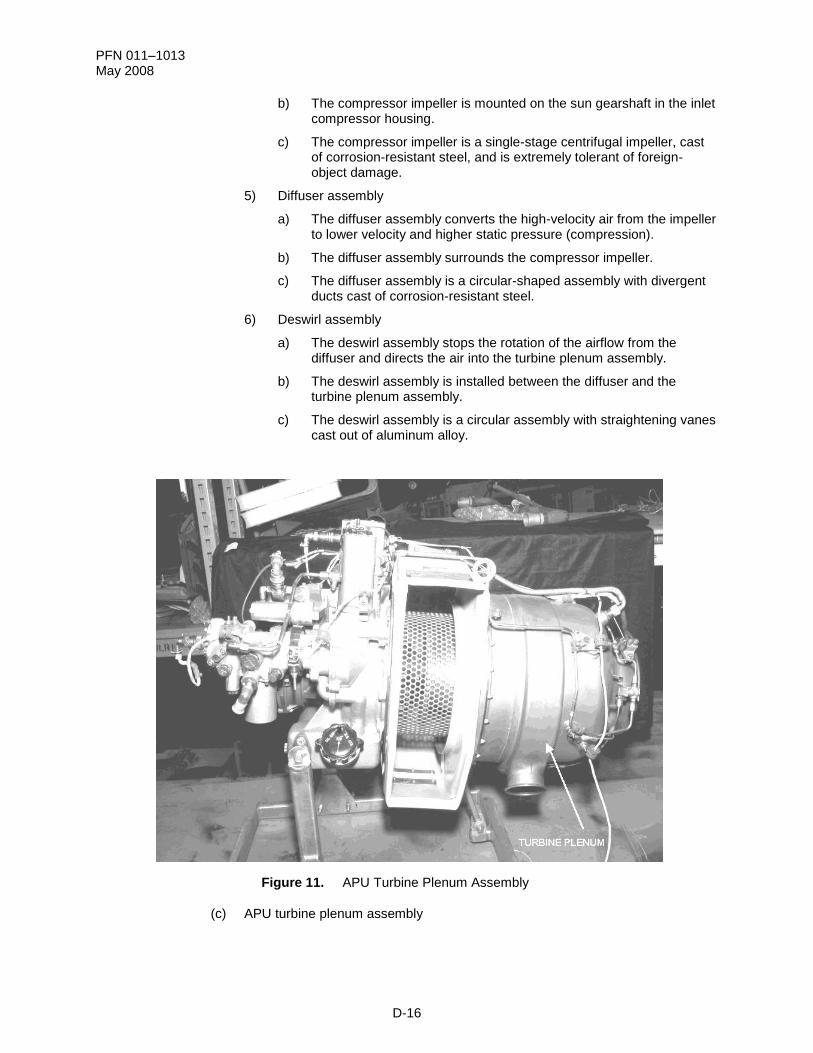
Figure 11. APU Turbine Plenum Assembly
(c) APU turbine plenum assembly
PFN 011–1013 May 2008
D-17
1) The APU turbine plenum assembly receives and contains the compressor discharge air from the deswirl assembly. It provides an enclosure for the combustion liner and serves as a cooling encasement for the hot turbine.
2) The APU turbine plenum assembly is installed directly behind the deswirl assembly and attached to the aft portion of the inlet housing. It contains a self-aligning bearing.
3) The APU turbine plenum assembly is constructed of corrosion-resistant steel and has an aluminum alloy lifting lug attached to the mounting flange at the 12 o'clock position. There is also an aluminum alloy mount assembly attached to the mounting flange at the 6 o'clock position.
4) The turbine plenum assembly has attachment flanges for the fuel manifold/atomizer assembly, the igniter plug, the Exhaust Gas Temperature (EGT) thermocouple, and an exhaust flange.
5) The turbine plenum assembly has a bleed port for attachment of the bleed control/load control valve and a drain check valve to drain any residual fuel from the turbine plenum upon completion of APU shutdown.
Figure 12. APU Load Control Valve
(d) Load Control Valve (LCV)
1) The LCV (also called the bleed control valve) controls and routes APU bleed air to the IPAS whenever APU NG is above 95%. It remains closed during APU start, below 95% APU NG, when the APU FIRE/READY switch is pressed, or when the APU is shut down.
2) The APU LCV is located on the lower left portion of the APU turbine plenum.
PFN 011–1013 May 2008
D-18
3) The APU LCV is a normally closed, electrically opened, 28 Vdc solenoid-operated, pneumatic diaphragm, metering valve. The body contains a butterfly-type valve with a position indicator (open and close).
4) During an APU start, the LCV is closed, which closes off the APU bleed air port to the IPAS manifold. The ECU opens the LCV when the APU NG reaches 95%. The LCV remains open during normal operations and
automatically begins to modulate at an EGT of 1283 25 F, providing more airflow for APU cooling. The LCV will remain open, even with the engine(s) operating at 100%, until the APU is shut off or the APU fire extinguishing system is armed.
Figure 13. APU Sections
(e) Combustor section
1) The combustor section provides the chamber where the compressor discharge air is mixed with atomized fuel and ignited.
2) The combustor is installed directly behind the deswirl assembly in the turbine plenum.
3) The combustor section consists of the combustion cap and combustor. The igniter plug and the fuel nozzle atomizers protrude into the combustor.
4) The combustor section is a reverse-flow annular design providing uniform airflow for combustion and cooling. A series of holes in the combustor provide for airflow into the combustor. Part of the air is used for combustion, and the rest acts as cooling air to prevent overheating of the combustor.
PFN 011–1013 May 2008
D-19
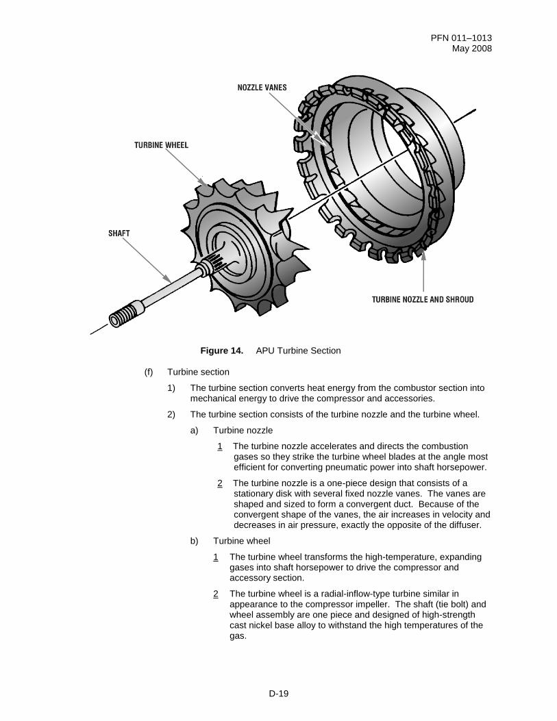
Figure 14. APU Turbine Section
(f) Turbine section
1) The turbine section converts heat energy from the combustor section into mechanical energy to drive the compressor and accessories.
2) The turbine section consists of the turbine nozzle and the turbine wheel.
a) Turbine nozzle
1 The turbine nozzle accelerates and directs the combustion gases so they strike the turbine wheel blades at the angle most efficient for converting pneumatic power into shaft horsepower.
2 The turbine nozzle is a one-piece design that consists of a stationary disk with several fixed nozzle vanes. The vanes are shaped and sized to form a convergent duct. Because of the convergent shape of the vanes, the air increases in velocity and decreases in air pressure, exactly the opposite of the diffuser.
b) Turbine wheel
1 The turbine wheel transforms the high-temperature, expanding gases into shaft horsepower to drive the compressor and accessory section.
2 The turbine wheel is a radial-inflow-type turbine similar in appearance to the compressor impeller. The shaft (tie bolt) and wheel assembly are one piece and designed of high-strength cast nickel base alloy to withstand the high temperatures of the gas.
PFN 011–1013 May 2008
D-20
Figure 15. APU Exhaust Sections
(g) Exhaust section
1) The exhaust section directs expended gases from the turbine section into the exhaust duct. It also creates cooling airflow across the APU.
2) The exhaust section is located aft of the turbine section and consists of the exhaust nozzle and exhaust duct.
a) Exhaust nozzle
1 The exhaust nozzle directs the exhaust gases from the turbine section into the exhaust duct.
2 The cone-shaped, corrosion-resistant steel exhaust nozzle is attached to the turbine plenum by a V-band coupling.
3 High-pressure gases expelled from the exhaust nozzle create a low-pressure area around the intake of the exhaust duct. This low-pressure area draws in ambient air, from around the APU, that helps cool the APU and reduces the temperature of the exhaust plume.
b) Exhaust duct
1 The exhaust duct allows mixing of ambient air and hot exhaust gas and creates airflow through the APU enclosure for cooling of APU external components.
2 The exhaust duct attaches to the aft panel of the APU enclosure and to the airframe, with a support bracket on the right side.
PFN 011–1013 May 2008
D-21
3 The exhaust duct is circular and bell shaped at the enclosure attachment point and transitions into a rectangular-shaped duct. It is constructed of stainless steel and covered with insulation made of heavy-duty flexible aluminum sandwiching a wire mesh screen.
Figure 16. APU Airflow
(5) APU power section airflow
(a) Air is drawn through a screen attached to the APU enclosure. The air inlet plenum directs ambient air to the inlet compressor housing.
(b) The compressor inlet housing screen prevents the entry of large debris that could cause foreign-object damage. As the compressor impeller rotates, air is drawn into the impeller blades near the center.
(c) The centrifugal action of the impeller causes the airflow to accelerate and leave the blades outward toward the rim of the compressor impeller. The accelerated air flows at high velocity into the diffuser assembly.
(d) The diffuser assembly reduces airflow velocity and increases pressure before the airflow enters the deswirl assembly.
(e) The deswirl assembly stops the rotation or swirl of the airflow and directs it into the turbine plenum.
(f) The air flows through the plenum and is directed into the combustion liner. When combustion occurs in the chamber, the expanding gases accelerate onto the turbine nozzle.
(g) The turbine nozzle will redirect the hot expanding gases at the most efficient angle to drive the turbine wheel.
PFN 011–1013 May 2008
D-22
(h) The turbine drives the compressor (mounted on a common shaft) and the accessory section.
(i) The exhaust gases flow into the exhaust nozzle, which is clamped to the turbine plenum, and are directed into the exhaust duct.
(j) The exhaust duct is bolted to the rear wall of the APU enclosure and directs the exhaust gases out of the helicopter.
PFN 011–1013 May 2008
D-23
2. Learning Step/Activity 2
Identify the characteristics of the APU accessory gearbox section.
Figure 17. APU Accessory Gearbox and Mounted Components
a. APU accessory gearbox section
(1) The accessory gearbox section reduces the turbine wheel rpm and contains mounting
pads for APU accessories. It also provides a means for starting the APU.
(2) The accessory gearbox section is mounted to the front of the power section.
NOTE: Each of the components listed below will be explained in its respective system.
(3) The APU accessory gearbox section provides mounting points for the following:
(a) Low oil pressure switch
(b) Oil filter
(c) Oil pump
(d) Oil level sight gauge (not shown)
(e) Magnetic chip/drain plug (not shown)
(f) Two forward mounts (right side not shown)
(g) Speed sensor motional transducer (not shown)
(h) PTO clutch
(i) Fuel control unit
(j) Fuel filter (not shown)
PFN 011–1013 May 2008
D-24
(k) Fuel shutoff solenoid valve
(l) Hydraulic start motor
(4) The lower portion of the gearbox forms the oil sump. A vent port located at the top of
the accessory gearbox section permits air/oil separation and relieves excessive
pressure.
(5) A test port located at the top of the accessory gearbox section is used for checking oil
pressure.
(6) Several oil-cooling fins, which provide maximum heat dissipation, are located at the
aft end of the accessory gearbox. The cooling fins are visible through the air inlet.
Figure 18. APU Gear Train
b. APU gear train
(1) Normal operation
(a) The APU accessory gearbox contains a high-speed pinion and planetary gear speed-reduction system that is mounted on the front of the power section of the APU.
(b) The turbine input drives the spur gearshaft (59,566 rpm) which drives three planetary gears (19,318.7 rpm).
(c) The planetary gears drive an internal ring gear (8216 rpm). The ring gear carrier is coupled to the PTO clutch input quill and provides an APU output of 8216 rpm.
(d) The pinion gear rotates an idler gear that drives the oil pump gear (2069.1 rpm). The oil pump gear drives the fuel control unit via a quill shaft.
PFN 011–1013 May 2008
D-25
(2) Start sequence
(a) During an APU start, the APU hydraulic start motor drives the starter gear, rotating the ring gear carrier.
(b) As the ring gear carrier rotates, it turns the ring gear that drives the planetary gears.
(c) The planetary gears drive the sun gearshaft, which starts the compressor impeller and the turbine wheel rotating.
Figure 19. APU Cross Section
c. APU bearings
(1) The bearings provide support for the APU main rotating components.
(2) The APU has bearings in the accessory gearbox section and the forward end of the
power section.
(3) Two ball bearings in the PTO clutch support the output drive assembly (grease
packed).
(a) The input of the PTO clutch supports the sliding plate, piston assembly, and input quill shaft.
(b) Two ball bearings support the APU power output ring gear carrier.
(c) Each planetary gear is supported by two ball bearings.
(d) A ball and roller bearing support the main rotating shaft.
PFN 011–1013 May 2008
D-26
1) The ball bearing at the accessory end of the shaft absorbs the radial and thrust shaft loads.
2) A roller bearing adjacent to the compressor absorbs the radial loads of the impeller and turbine.
PFN 011–1013 May 2008
D-27
Check On Learning
1. The air inlet plenum directs inlet airflow to the compressor section and isolates the APU intake airflow from what?
ACTION: Identify the characteristics of the APU-related systems.
CONDITIONS: Given a written test utilizing the IETM without the use of student notes or references.
STANDARD: In accordance with TM 1-1520-251-10 and TM 1-1520-LONGBOW/APACHE IETM.
1. Learning Step/Activity 1
Identify the characteristics of the APU lubrication system.
a. Four major APU-related systems provide for the operation and control of the APU: the lubrication system, fuel system, electrical system, and start system.
Figure 20. APU Lubrication System
b. APU Lubrication System
(1) The APU Lubrication System stores and distributes oil for lubrication and cooling of
vital engine components.
(2) The lubrication system cleans the APU by carrying sludge and other residues away
from the moving APU parts and depositing them in the oil filter.
(3) The APU Lubrication System supplies pressurized oil flow for operations of the PTO
clutch.
(4) APU Lubrication System components
(a) Oil sump
PFN 011–1013 May 2008
D-29
(b) Oil pump
(c) Oil filter
(d) Low oil pressure switch
(e) PTO clutch
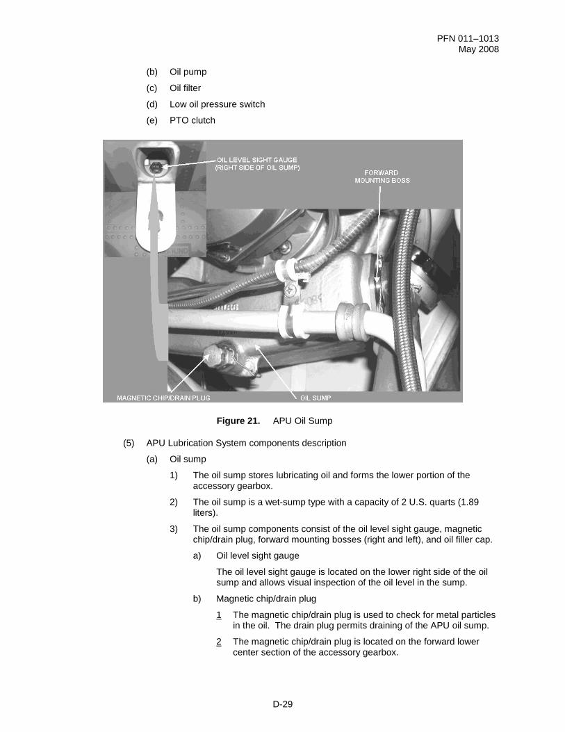
Figure 21. APU Oil Sump
(5) APU Lubrication System components description
(a) Oil sump
1) The oil sump stores lubricating oil and forms the lower portion of the accessory gearbox.
2) The oil sump is a wet-sump type with a capacity of 2 U.S. quarts (1.89 liters).
3) The oil sump components consist of the oil level sight gauge, magnetic chip/drain plug, forward mounting bosses (right and left), and oil filler cap.
a) Oil level sight gauge
The oil level sight gauge is located on the lower right side of the oil sump and allows visual inspection of the oil level in the sump.
b) Magnetic chip/drain plug
1 The magnetic chip/drain plug is used to check for metal particles in the oil. The drain plug permits draining of the APU oil sump.
2 The magnetic chip/drain plug is located on the forward lower center section of the accessory gearbox.
PFN 011–1013 May 2008
D-30
3 The magnetic chip/drain plug incorporates a permanent magnet that attracts ferrous metal particles.
4 The magnetic chip detector is not connected to the warning, caution, and advisory system; it must be visually inspected.
5 A check valve and spring within the drain plug prevent oil in the sump from leaking when the chip plug is removed.
6 The magnetic chip/drain plug is removed by pushing in and turning the knurled knob counterclockwise. To drain oil from the sump, a special unit is installed in place of the chip detector/drain plug to hold open the valve and allow oil to drain.
c) Forward mounting bosses (right and left)
1 The forward mounting bosses provide the aligning and attaching points for the forward APU mounts.
2 The forward mounting bosses are located on the forward outboard portion of the oil sump, one left and one right.
3 The forward mounting bosses have a center alignment recess and two bolt holes that provide for boss attachment to the sump.
Figure 22. APU Oil Sump Filler Cap
d) Oil sump filler cap
1 The oil sump filler cap provides access for servicing the APU oil system and prevents contaminants from entering the lubrication system.
PFN 011–1013 May 2008
D-31
2 The filler cap is located on the left side of the accessory gearbox section and is attached with a chain.
3 A dipstick, affixed to the underside of the filler cap, allows direct checking of the oil level.
4 The over board vent tube vents air from the oil tank.
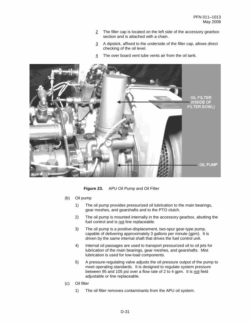
Figure 23. APU Oil Pump and Oil Filter
(b) Oil pump
1) The oil pump provides pressurized oil lubrication to the main bearings, gear meshes, and gearshafts and to the PTO clutch.
2) The oil pump is mounted internally in the accessory gearbox, abutting the fuel control and is not line replaceable.
3) The oil pump is a positive-displacement, two-spur gear-type pump, capable of delivering approximately 3 gallons per minute (gpm). It is driven by the same internal shaft that drives the fuel control unit.
4) Internal oil passages are used to transport pressurized oil to oil jets for lubrication of the main bearings, gear meshes, and gearshafts. Mist lubrication is used for low-load components.
5) A pressure-regulating valve adjusts the oil pressure output of the pump to meet operating standards. It is designed to regulate system pressure between 95 and 105 psi over a flow rate of 2 to 4 gpm. It is not field adjustable or line replaceable.
(c) Oil filter
1) The oil filter removes contaminants from the APU oil system.
PFN 011–1013 May 2008
D-32
2) The oil filter is mounted on top of the accessory gearbox left side, at approximately the 11 o'clock position.
3) The oil filter is a disposable paper filter with a filter rated at 10 microns nominal and 25 microns absolute. It has no bypass capabilities.
4) A clogged filter will cause loss of oil pressure, which results in APU shutdown.
Figure 24. APU Low Oil Pressure Switch
(d) Low oil pressure switch
1) The Low Oil Pressure (LOP) switch monitors the oil pressure and signals the ECU when oil pressure is low.
2) The LOP switch is located on top of the accessory gearbox section, to the right of the oil filter.
3) The LOP switch is a normally closed (to ground), solenoid-operated, pressure switch. When oil pressure decreases to below 75 psi, the switch is activated and signals the ECU, which will turn on the APU FAIL caution message and automatically shut down the APU.
4) During APU acceleration, when oil pressure reaches 76 to 90 psi, the switch will open. Opening of the switch removes the ground path to the ECU and System Processor (SP) logic circuits that control shutdown and the APU FAIL message.
5) If oil pressure is not sufficient to open the switch or if the switch remains closed at 95% APU NG for 10 seconds, the ECU will shut down the APU.
PFN 011–1013 May 2008
D-33
Figure 25. PTO Clutch
(e) PTO clutch
1) The PTO clutch provides coupling and decoupling between the APU and the main transmission accessory gear train assembly through the number seven driveshaft.
2) The PTO clutch is mounted on the forward center section of the APU accessory gearbox.
PFN 011–1013 May 2008
D-34
Figure 26. PTO Clutch Cross Section
3) The ECU and the SP automatically control the PTO Clutch.
4) It is hydraulically actuated by the APU lubrication system through the clutch Torque Limiting Control Valve (TLCV) (solenoid valve).
5) The clutch has a back-up bearing system with two sets of grease lubricated ceramic ball bearings.
6) In the event of a primary bearing failure, or loss of centerline control, a secondary (back-up) set of bearings supports the clutch output housing and the “wrap-back” flange that attaches to the APU shaft.
7) The PTO clutch employs a Shaft Displacement Detector (SDD) to detect a loss of centerline control or out-of-balance condition of the output adapter shaft. The SDD is a passive circuit design, essentially a “jumper” or loop of wire, which interrupts fuel delivery to the APU when the wire is severed due to contact with the output adapter shaft. The SDD can be disconnected to override this protection feature and allow subsequent APU operation.
8) The solenoid directs APU oil for engagement and disengagement of the clutch. The solenoid is an electrically controlled, two-way, ball-type valve that directs oil into piston chambers to engage or disengage the clutch. The clutch solenoid limits the torque applied to the main transmission accessory gearbox during engagement to 1400 in. lb.
9) The clutch has two internal oil chambers separated by a piston. The clutch solenoid pressurizes one chamber with APU oil for clutch engagement and the other for disengagement.
10) A steel bellows seal is attached to the piston and the left chamber wall. In addition to sealing, while permitting axial movement, the bellows functions
TORQUE LIMITING
CONTROL VALVE
(SOLENOID VALVE)
SPLINED
ADAPTER
DRY
FRICTION DISK
STATIONARY
PLATE
LEFT CHAMBER
RIGHT CHAMBER
BELLOWS SEAL
SLIDING PLATE
INPUT QUILL SHAFT
OUTPUT DRIVE
SHAFT
DISPLACEMENT
DETECTOR
WRAP-BACK
FLANGE
PFN 011–1013 May 2008
D-35
as a spring and exerts a holdback force of 45 pounds that tends to push the piston toward the disengage position.
11) A sliding plate is mounted on an input quill shaft. A dry friction disc is used to transfer APU power from the input quill shaft to the output drive. The friction disc is made from a proprietary bronze compound. The clutch is designed for a friction disc life of 3000 engagements at 60% APU NG and 0% accessory gearbox speed. A friction disk inspection hole is provided under the PTO clutch data plate.
12) Teeth on the friction disk mate with the splined adapter, which will transmit shaft power to the output flange when the sliding plate comes into contact with the disk. A stationary plate supports the dry friction disk as the sliding plate makes contact.
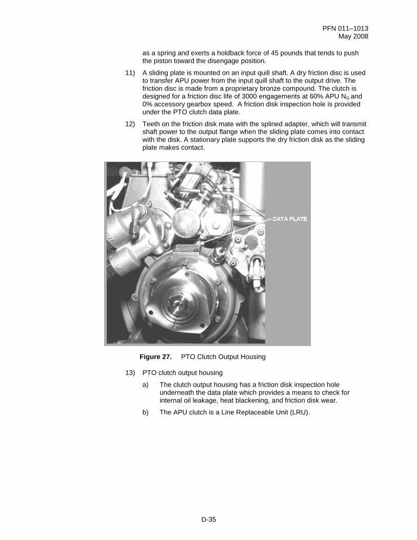
Figure 27. PTO Clutch Output Housing
13) PTO clutch output housing
a) The clutch output housing has a friction disk inspection hole underneath the data plate which provides a means to check for internal oil leakage, heat blackening, and friction disk wear.
b) The APU clutch is a Line Replaceable Unit (LRU).
PFN 011–1013 May 2008
D-36
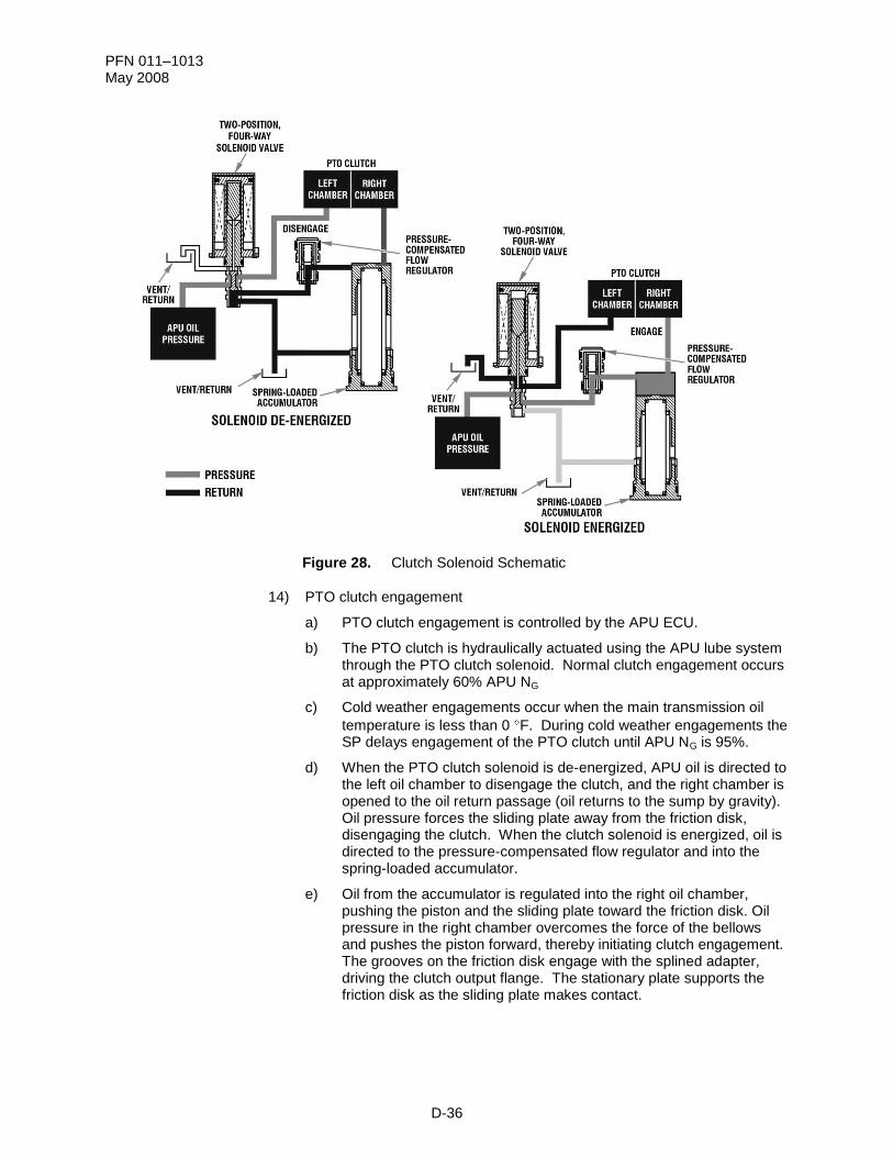
Figure 28. Clutch Solenoid Schematic
14) PTO clutch engagement
a) PTO clutch engagement is controlled by the APU ECU.
b) The PTO clutch is hydraulically actuated using the APU lube system through the PTO clutch solenoid. Normal clutch engagement occurs at approximately 60% APU NG
c) Cold weather engagements occur when the main transmission oil
temperature is less than 0 F. During cold weather engagements the SP delays engagement of the PTO clutch until APU NG is 95%.
d) When the PTO clutch solenoid is de-energized, APU oil is directed to the left oil chamber to disengage the clutch, and the right chamber is opened to the oil return passage (oil returns to the sump by gravity). Oil pressure forces the sliding plate away from the friction disk, disengaging the clutch. When the clutch solenoid is energized, oil is directed to the pressure-compensated flow regulator and into the spring-loaded accumulator.
e) Oil from the accumulator is regulated into the right oil chamber, pushing the piston and the sliding plate toward the friction disk. Oil pressure in the right chamber overcomes the force of the bellows and pushes the piston forward, thereby initiating clutch engagement. The grooves on the friction disk engage with the splined adapter, driving the clutch output flange. The stationary plate supports the friction disk as the sliding plate makes contact.
PFN 011–1013 May 2008
D-37
Figure 29. APU Lubrication System
(6) APU lubrication system operation
(a) The oil pump draws oil directly from the sump through a pickup tube and forces the oil through passageways and jets. The pump is designed to support a greater flow volume than is normally required by the system.
(b) All excess oil pressure is relieved from the return oil to the sump through the pressure regulator valve. The valve is calibrated to regulate the pressure at 95 to 105 psi, which provides for the optimum flow of oil to all gear meshes and bearings.
(c) From start to 59% APU NG, the PTO clutch solenoid is de-energized, and high-pressure oil is directed to the left chamber of the PTO clutch. The combined forces of the bellows and oil pressure hold the PTO clutch in the disengaged position.
(d) When APU NG reaches 60%, the ECU will energize the PTO clutch solenoid valve. Oil is then directed to the right chamber, and the left chamber is opened to the return passage. This allows the oil in the left chamber to return to the sump by gravity. Oil pressure in the right chamber overcomes the bellows spring force and forces the piston to the left to engage the PTO clutch.
NOTE: If the main rotor speed is above 95%, PTO clutch engagement will not take place.
(e) Oil passes through the filter, where contaminants are removed from the oil. Oil is then routed to the LOP switch, fuel control unit, and the oil orifice.
(f) As the oil is directed to the LOP switch, it will activate the normally closed switch to the open position. The ECU will confirm that the oil pressure has exceeded
PFN 011–1013 May 2008
D-38
75 psi for 10 seconds when APU NG has reached 95%; if not, the ECU will terminate APU operation.
(g) The oil directed to the fuel control unit will lubricate the quill shaft gear mesh.
(h) From the oil orifice, the reduced oil pressure (55–70 psi) is routed through oil passages to oil jets for lubrication of main shaft bearings, gear mesh points, start clutch bearings, and the planetary gear system bearings.
(i) The returning oil is gravity fed back to the oil sump, eliminating the need for an oil scavenge pump. The oil is cooled through conduction to the tank walls, which have integral-cast cooling fins to support efficient heat dissipation.
PFN 011–1013 May 2008
D-39
2. Learning Step/Activity 2
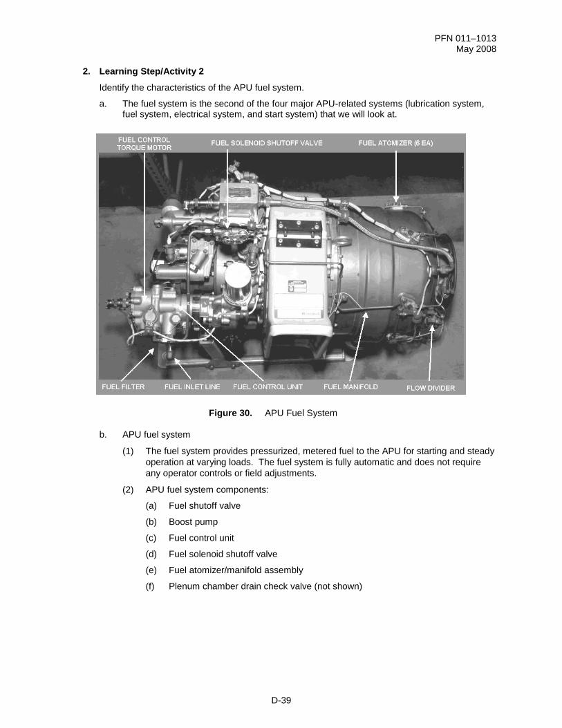
Identify the characteristics of the APU fuel system.
a. The fuel system is the second of the four major APU-related systems (lubrication system, fuel system, electrical system, and start system) that we will look at.
Figure 30. APU Fuel System
b. APU fuel system
(1) The fuel system provides pressurized, metered fuel to the APU for starting and steady
operation at varying loads. The fuel system is fully automatic and does not require
any operator controls or field adjustments.
(2) APU fuel system components:
(a) Fuel shutoff valve
(b) Boost pump
(c) Fuel control unit
(d) Fuel solenoid shutoff valve
(e) Fuel atomizer/manifold assembly
(f) Plenum chamber drain check valve (not shown)
PFN 011–1013 May 2008
D-40
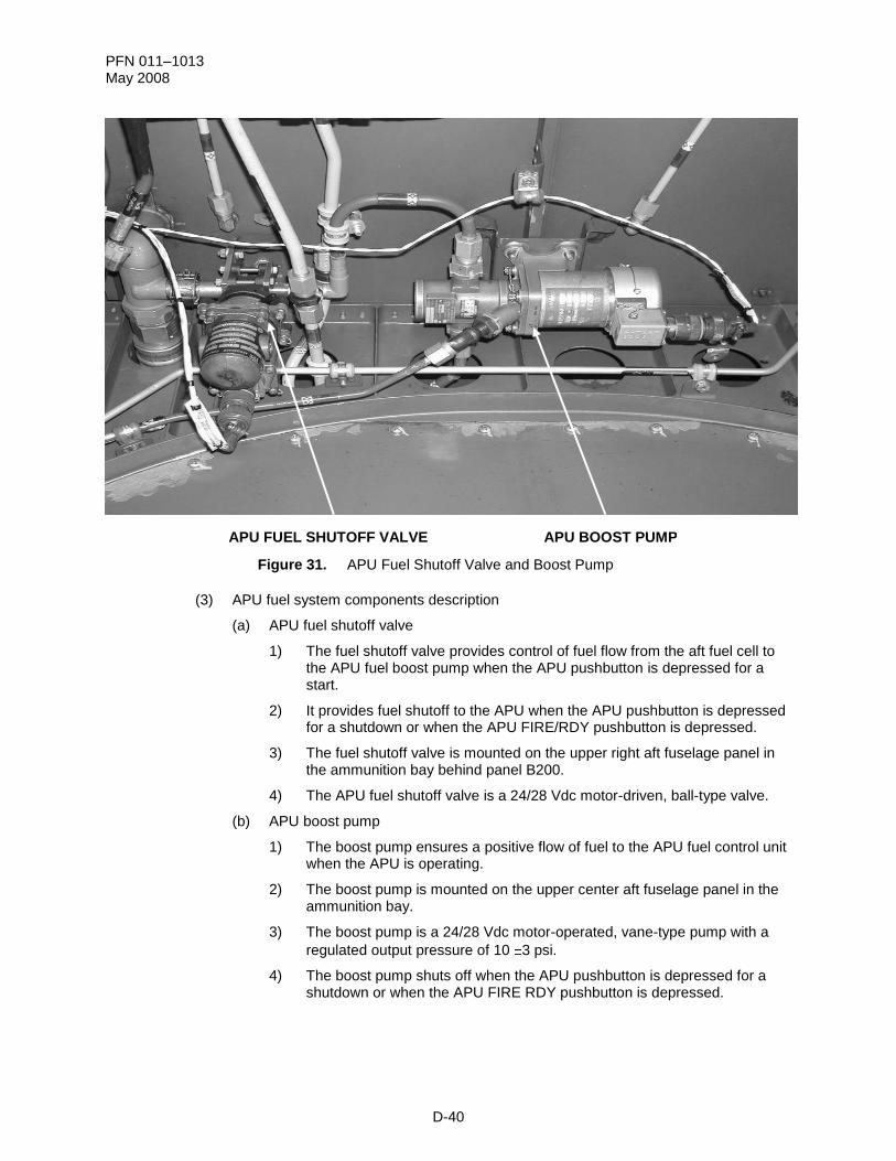
Figure 31. APU Fuel Shutoff Valve and Boost Pump
(3) APU fuel system components description
(a) APU fuel shutoff valve
1) The fuel shutoff valve provides control of fuel flow from the aft fuel cell to the APU fuel boost pump when the APU pushbutton is depressed for a start.
2) It provides fuel shutoff to the APU when the APU pushbutton is depressed for a shutdown or when the APU FIRE/RDY pushbutton is depressed.
3) The fuel shutoff valve is mounted on the upper right aft fuselage panel in the ammunition bay behind panel B200.
4) The APU fuel shutoff valve is a 24/28 Vdc motor-driven, ball-type valve.
(b) APU boost pump
1) The boost pump ensures a positive flow of fuel to the APU fuel control unit when the APU is operating.
2) The boost pump is mounted on the upper center aft fuselage panel in the ammunition bay.
3) The boost pump is a 24/28 Vdc motor-operated, vane-type pump with a
regulated output pressure of 10 3 psi.
4) The boost pump shuts off when the APU pushbutton is depressed for a shutdown or when the APU FIRE RDY pushbutton is depressed.
APU BOOST PUMP APU FUEL SHUTOFF VALVE
PFN 011–1013 May 2008
D-41
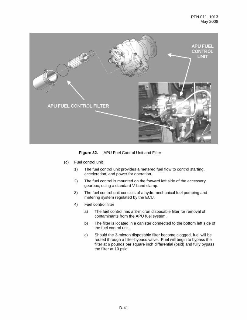
Figure 32. APU Fuel Control Unit and Filter
(c) Fuel control unit
1) The fuel control unit provides a metered fuel flow to control starting, acceleration, and power for operation.
2) The fuel control is mounted on the forward left side of the accessory gearbox, using a standard V-band clamp.
3) The fuel control unit consists of a hydromechanical fuel pumping and metering system regulated by the ECU.
4) Fuel control filter
a) The fuel control has a 3-micron disposable filter for removal of contaminants from the APU fuel system.
b) The filter is located in a canister connected to the bottom left side of the fuel control unit.
c) Should the 3-micron disposable filter become clogged, fuel will be routed through a filter-bypass valve. Fuel will begin to bypass the filter at 6 pounds per square inch differential (psid) and fully bypass the filter at 10 psid.
PFN 011–1013 May 2008
D-42
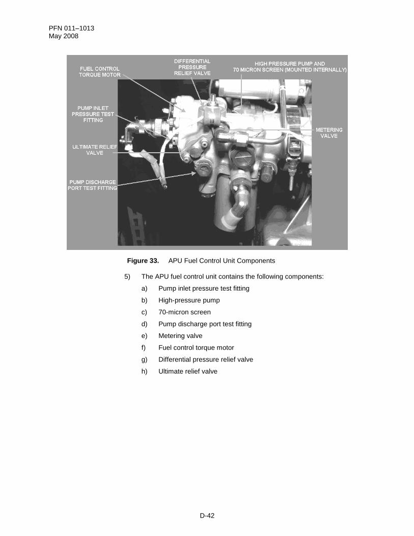
Figure 33. APU Fuel Control Unit Components
5) The APU fuel control unit contains the following components:
a) Pump inlet pressure test fitting
b) High-pressure pump
c) 70-micron screen
d) Pump discharge port test fitting
e) Metering valve
f) Fuel control torque motor
g) Differential pressure relief valve
h) Ultimate relief valve
PFN 011–1013 May 2008
D-43
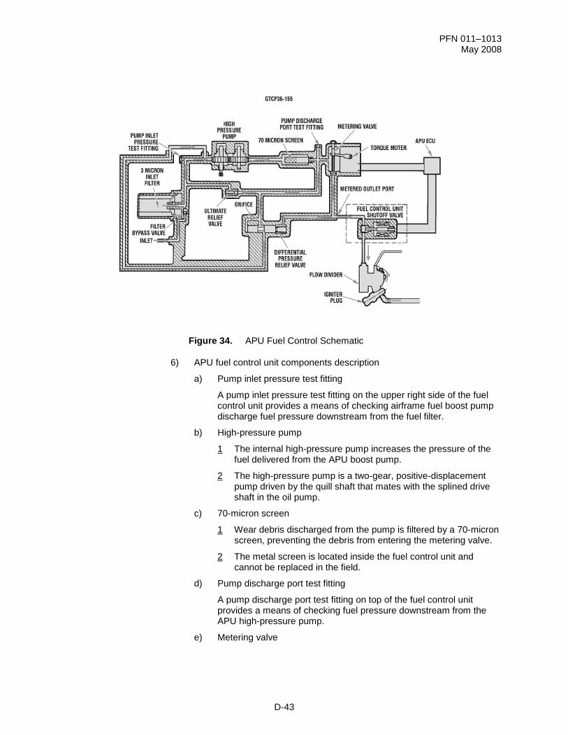
Figure 34. APU Fuel Control Schematic
6) APU fuel control unit components description
a) Pump inlet pressure test fitting
A pump inlet pressure test fitting on the upper right side of the fuel control unit provides a means of checking airframe fuel boost pump discharge fuel pressure downstream from the fuel filter.
b) High-pressure pump
1 The internal high-pressure pump increases the pressure of the fuel delivered from the APU boost pump.
2 The high-pressure pump is a two-gear, positive-displacement pump driven by the quill shaft that mates with the splined drive shaft in the oil pump.
c) 70-micron screen
1 Wear debris discharged from the pump is filtered by a 70-micron screen, preventing the debris from entering the metering valve.
2 The metal screen is located inside the fuel control unit and cannot be replaced in the field.
d) Pump discharge port test fitting
A pump discharge port test fitting on top of the fuel control unit provides a means of checking fuel pressure downstream from the APU high-pressure pump.
e) Metering valve
PFN 011–1013 May 2008
D-44
1 The metering valve establishes high-pressure fuel flow to the APU fuel nozzle at 250 to 300 psi.
2 The metering valve is located inside the torque motor assembly portion of the fuel control unit.
3 The metering valve consists of a balanced clevis that slides across an orifice. As the clevis moves across the orifice, it increases or decreases the area of the orifice, allowing more or less fuel to flow. The clevis is driven by an ECU-controlled torque motor.
f) Fuel control torque motor
1 The fuel control torque motor drives the metering valve to maintain proper speed under all operating conditions.
2 The electronically controlled motor is mounted on the side of the fuel control unit.
g) Differential pressure relief valve
1 The differential pressure relief valve maintains a constant fuel pressure drop of 25 psi across the metering valve.
2 The differential pressure relief valve consists of a preset tension spring and plunger located inside the fuel control unit.
h) Ultimate relief valve
1 The ultimate relief valve bypasses excess fuel pressure whenever the pressure cannot be relieved by the differential pressure valve.
2 The ultimate relief valve consists of a preset tension spring and ball located inside the fuel control unit.
3 The ultimate relief valve will open to allow any abnormally high-pressure fuel to be routed back into the high-pressure pump inlet. Typically, the valve functions when the APU rpm is above 95% and a shutdown occurs.
7) Fuel control operation
a) Fuel flow is programmed by the ECU.
b) During an overspeed situation, the ECU automatically closes the fuel solenoid valve to shut down the APU at 108% NG. At 109% APU NG, the ECU will signal the fuel control torque motor to be driven to the closed position. This provides a dual shutdown feature.
PFN 011–1013 May 2008
D-45
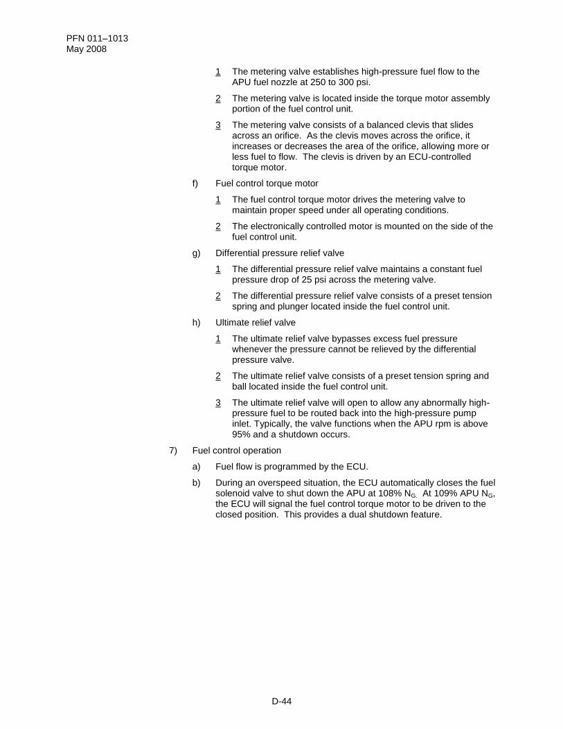
Figure 35. APU Fuel Solenoid Shutoff Valve
(d) Fuel solenoid Shutoff Valve (SOV)
1) The fuel solenoid SOV allows fuel pressure to build up before being released to the APU fuel nozzle. It also stops fuel flow to the fuel nozzles to cause APU shutdown when the APU START pushbutton is pushed.
2) The fuel solenoid SOV is located on top of the accessory gearbox section, between the APU fuel control unit and the APU fuel nozzle manifold. Do not confuse this valve with the APU fuel shutoff valve located between the fuel cell and the APU fuel boost pump.
3) The fuel solenoid SOV is a normally closed, straight-through flow, electrically actuated solenoid valve controlled by the APU ECU.
4) During starts, the fuel solenoid SOV remains closed until APU NG reaches 5%. This allows time for fuel pressure to rise high enough for APU light-off. During the initial start period, engine speed is too slow to provide a fuel pressure high enough for light-off.
5) Operation
a) When the solenoid is de-energized, the plunger is positioned at the base of the valve body so that the spring between the carbon discs forces the discs to contact the seat faces, obstructing the seat holes. Incoming fuel pressure overcomes the spring force against the inlet carbon disc and gets between the carbon discs. This forces the downstream disc tightly against the lapped seat.
b) When the solenoid is energized, the plunger is magnetically retracted upward, sliding the discs over the seat faces until they clear the holes in the seats. The fuel then passes through the valve body to the fuel nozzle.
PFN 011–1013 May 2008
D-46
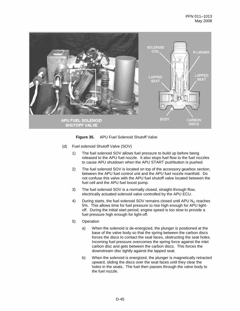
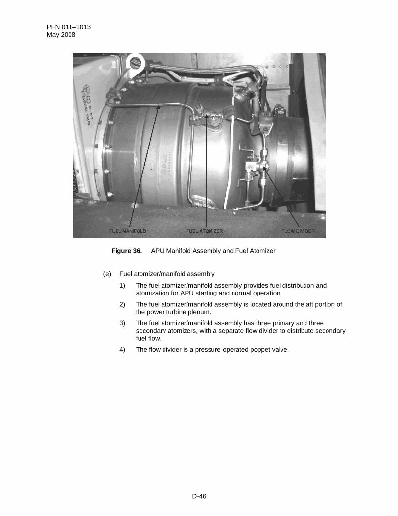
Figure 36. APU Manifold Assembly and Fuel Atomizer
(e) Fuel atomizer/manifold assembly
1) The fuel atomizer/manifold assembly provides fuel distribution and atomization for APU starting and normal operation.
2) The fuel atomizer/manifold assembly is located around the aft portion of the power turbine plenum.
3) The fuel atomizer/manifold assembly has three primary and three secondary atomizers, with a separate flow divider to distribute secondary fuel flow.
4) The flow divider is a pressure-operated poppet valve.
PFN 011–1013 May 2008
D-47
Figure 37. APU Fuel Atomizer
5) Fuel atomizers
a) The fuel is atomized to the combustor section during APU operation.
b) The fuel nozzles consist of a primary flow nozzle, secondary flow nozzle, and piloted air blast atomizer orifice.
6) Operation
a) Compressor discharge air flows through the holes of the combustion liner into the airblast ports.
b) The air flowing through the outer ports assists in the shaping of the spray pattern of the secondary fuel flow.
c) The air flowing through the inner port precludes fuel from carbonizing around the primary orifice while fuel is flowing and blows across the face of the primary orifice on shutdown, reducing caking of the orifice.
d) High-pressure fuel is introduced into the inlet port and flows through an internal screen. This screen prevents the plugging of the metered orifice and flow passages.
e) The primary fuel nozzle provides atomized fuel to the combustor during the initial APU start cycle.
f) As the APU accelerates, and the fuel flow increases, the pressure drop increases across the atomizer.
g) At a preset constant differential pressure setting, the flow divider will open and allow fuel to flow to the secondary nozzle
h) Both fuel flow paths (primary and secondary) supply fuel to the APU combustor section when the APU is at operating speed.
PFN 011–1013 May 2008
D-48
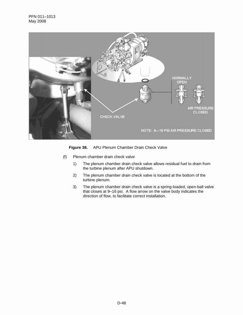
Figure 38. APU Plenum Chamber Drain Check Valve
(f) Plenum chamber drain check valve
1) The plenum chamber drain check valve allows residual fuel to drain from the turbine plenum after APU shutdown.
2) The plenum chamber drain check valve is located at the bottom of the turbine plenum.
3) The plenum chamber drain check valve is a spring-loaded, open-ball valve that closes at 9–16 psi. A flow arrow on the valve body indicates the direction of flow, to facilitate correct installation.
PFN 011–1013 May 2008
D-49
Figure 39. APU Fuel System
(4) APU Fuel System operation
(a) When the APU START pushbutton switch is pushed, the helicopter-mounted APU fuel shutoff valve and the helicopter-mounted APU boost pump are energized.
(b) Fuel is drawn from the aft fuel cell, routed through the APU fuel shutoff valve, and pressurized by the boost pump to 10 psi.
(c) From the boost pump, fuel is routed through the 3-micron fuel control inlet filter that removes contaminants from the fuel.
(d) If the inlet fuel filter becomes clogged, a filter-bypass valve will begin to open at 6 psi (and be fully open at 10 psi), and fuel will pass to the high-pressure pump.
(e) The high-pressure pump increases fuel pressure and discharges it through a 70-micron screen to the metering valve, differential pressure relief valve, and ultimate relief valve.
(f) The differential pressure relief valve will maintain a constant fuel pressure drop of 25 psi across the metering valve.
(g) In the event of excessive pump discharge, the ultimate relief valve will open and allow the high-pressure fuel to flow back into the high-pressure pump inlet port.
(h) High-pressure fuel from the metering valve is directed through fuel flex lines to the fuel shutoff solenoid valve.
(i) When APU NG reaches 5% during start, the ECU will open the fuel solenoid shutoff valve, allowing the high-pressure fuel to flow through fuel lines to the APU fuel manifold.
PFN 011–1013 May 2008
D-50
(j) The fuel manifold and flow divider will direct the high-pressure fuel to the primary atomizers during APU start and to primary and secondary atomizers during APU normal operations.
(k) The high-pressure fuel will be atomized by the fuel nozzle for combustion in the combustor chamber.
(l) A plenum chamber drain check valve (normally closed during APU operations) will open upon shutdown to drain residual fuel.
PFN 011–1013 May 2008
D-51
3. Learning Step/Activity 3
Identify the characteristics of the APU Electrical System.
a. The electrical system is the third of four major APU-related systems (lubrication system, fuel system, electrical system, and start system) that we will discuss.
b. APU electrical system
(1) The APU Electrical System provides fully automatic control of APU operation.
(2) Electrical system components:
(a) Circuit breakers
(b) APU pushbutton
(c) Rotor rpm NR sensor
(d) Rotor speed isolation transformer
(e) APU speed sensor
(f) APU ignition system
(g) EGT thermocouple
(h) APU elapsed-time indicator
(i) APU ECU
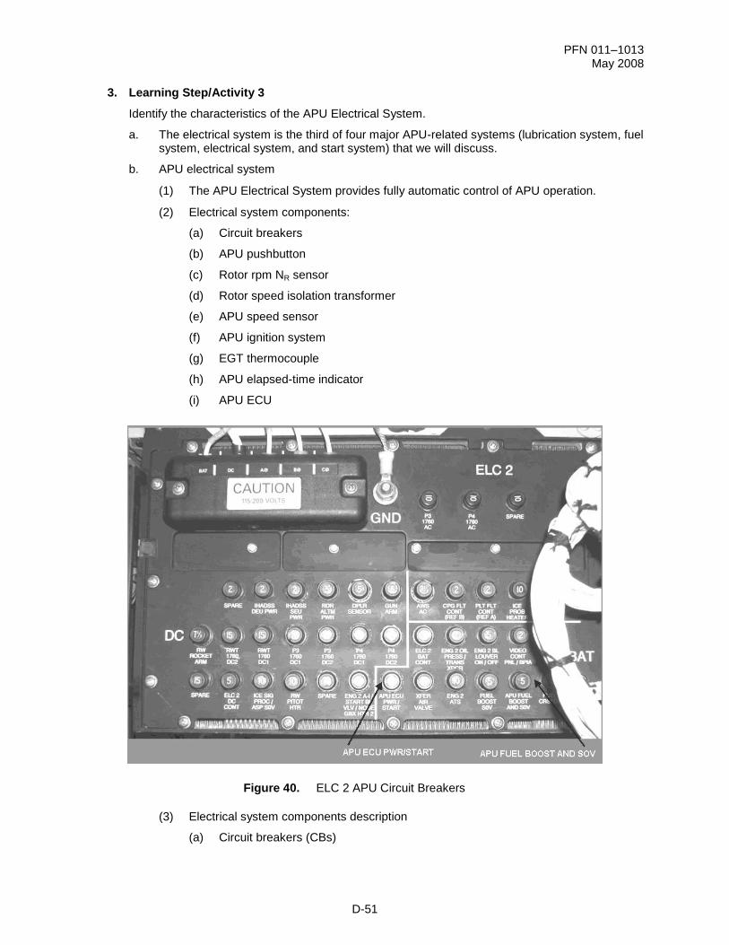
Figure 40. ELC 2 APU Circuit Breakers
(3) Electrical system components description
(a) Circuit breakers (CBs)
PFN 011–1013 May 2008
D-52
1) There are two CBs on Electrical Load Center 2 (ELC NO. 2) directly related to APU function.
2) APU ECU PWR/START. The APU ECU PWR/START CB protects and provides power to the start command circuitry in the ECU.
3) APU FUEL BOOST AND SOV
a) The APU FUEL BOOST AND SOV CB protects and provides power to the APU fuel boost pump and the fuel shutoff valve.
b) The APU FUEL BOOST AND SOV CB provides the interlock between the PLT and CPG FIRE DET/EXT panels and the fuel boost pump and fuel shutoff valve.
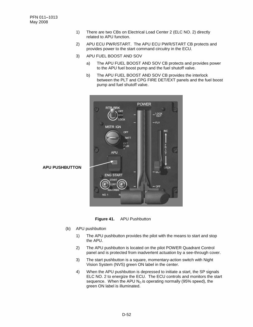
Figure 41. APU Pushbutton
(b) APU pushbutton
1) The APU pushbutton provides the pilot with the means to start and stop the APU.
2) The APU pushbutton is located on the pilot POWER Quadrant Control panel and is protected from inadvertent actuation by a see-through cover.
3) The start pushbutton is a square, momentary-action switch with Night Vision System (NVS) green ON label in the center.
4) When the APU pushbutton is depressed to initiate a start, the SP signals ELC NO. 2 to energize the ECU. The ECU controls and monitors the start sequence. When the APU NG is operating normally (95% speed), the green ON label is illuminated.
APU PUSHBUTTON
PFN 011–1013 May 2008
D-53
5) When the pushbutton is depressed with the APU operating, the SP signals the ECU to shut down the APU. The APU ON light extinguishes when the APU rpm decreases to below 95%.
Figure 42. Rotor RPM Sensor and Rotor Speed Isolation Transformer
(c) Rotor rpm (NR) sensor
1) The NR sensor senses main rotor speed and sends a signal to the SP and the ECU.
2) The NR sensor is mounted to the aft left side of the main transmission accessory section.
3) The NR sensor is a monopole magnetic pickup that measures the percent of rotor speed by electrically counting the teeth of the primary geartrain in the transmission.
(d) Rotor speed isolation transformer
1) The rotor speed isolation transformer couples the rotor rpm sensor output signal to the ECU.
2) The rotor speed isolation transformer is mounted on a bracket that is attached to the aft upper left side of the accessory section of the transmission.
3) The rotor speed isolation transformer is approximately 1-inch square with a rigid plastic housing. It contains a decal with a circuit diagram.
PFN 011–1013 May 2008
D-54
Figure 43. Main Rotor Speed Signal
4) The SP uses the NR speed signal to provide the NR display on the Multi Purpose Display (MPD) ENG page and the HIGH RTR and LOW RTR warnings on the Up-Front Display (UFD).
5) The NR speed signal is used by the ECU to engage the PTO clutch when NR is below 95% and to prevent PTO clutch engagement when the NR is above 95%.
PFN 011–1013 May 2008
D-55
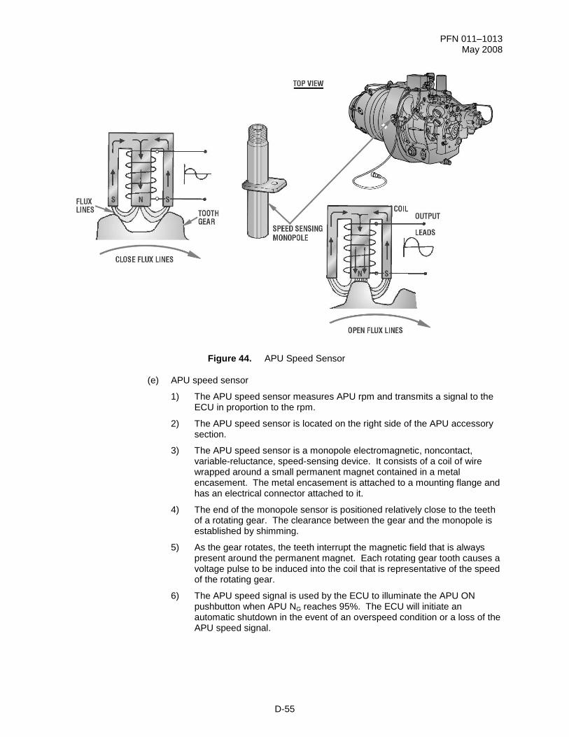
Figure 44. APU Speed Sensor
(e) APU speed sensor
1) The APU speed sensor measures APU rpm and transmits a signal to the ECU in proportion to the rpm.
2) The APU speed sensor is located on the right side of the APU accessory section.
3) The APU speed sensor is a monopole electromagnetic, noncontact, variable-reluctance, speed-sensing device. It consists of a coil of wire wrapped around a small permanent magnet contained in a metal encasement. The metal encasement is attached to a mounting flange and has an electrical connector attached to it.
4) The end of the monopole sensor is positioned relatively close to the teeth of a rotating gear. The clearance between the gear and the monopole is established by shimming.
5) As the gear rotates, the teeth interrupt the magnetic field that is always present around the permanent magnet. Each rotating gear tooth causes a voltage pulse to be induced into the coil that is representative of the speed of the rotating gear.
6) The APU speed signal is used by the ECU to illuminate the APU ON pushbutton when APU NG reaches 95%. The ECU will initiate an automatic shutdown in the event of an overspeed condition or a loss of the APU speed signal.
PFN 011–1013 May 2008
D-56
Figure 45. APU Ignition System
(f) APU Ignition System
1) The ignition system provides electrical current for APU combustion only during startup.
2) The ignition system consists of the ignition unit, igniter lead, and igniter plug.
a) Ignition unit
1 The ignition unit increases the low-voltage (24 Vdc) input from the battery to a high-voltage output (2900 to 3200 Vdc) and supplies a series of high-energy sparks to the APU igniter plug.
2 The ignition unit is mounted on the right side of the top of the accessory gearbox, at approximately the 1 o'clock position.
3 The ignition unit is a sealed capacitive-discharge assembly.
b) Igniter lead
1 The igniter lead carries high-voltage electrical current from the igniter unit to the igniter plug.
2 One end of the lead is attached to the ignition unit; the other end is attached to the igniter plug.
c) Igniter plug
1 The igniter plug provides the spark in the combustor to ignite the fuel/air mixture during the start sequence.
IGNITION LEAD
PFN 011–1013 May 2008
D-57
2 The igniter plug is located on the upper portion of the turbine plenum.
3 The igniter plug consists of a center electrode, insulator, and outer shell.
3) The ignition system provides a series of sparks to ignite the atomized fuel in the combustor. The ignition system is energized by the ECU when APU NG reaches 5% and remains energized until 4 seconds after APU NG reaches 95%.
Figure 46. EGT Thermocouple
(g) EGT thermocouple
1) The EGT thermocouple provides an electrical signal to the ECU that is in proportion to the exhaust gas temperature.
2) The EGT thermocouple is mounted at the 10 o'clock position on the APU turbine plenum and passes into the APU exhaust section. A nonadjustable flange mount is positioned to completely immerse the thermocouple in the exhaust gas.
3) The EGT thermocouple is a junction of two dissimilar metals (chromel and alumel). When heat is applied, a voltage is generated in proportion to the difference in temperature between the hot and cold end of the thermocouple. The generated millivolt signal is sensed by the ECU and equates to the temperature of the exhaust gas.
(h) APU elapsed-time indicator
1) The elapsed-time indicator indicates the operating hours of the APU.
PFN 011–1013 May 2008
D-58
2) The elapsed-time indicator is mounted on the top of the APU enclosure, forward of the ECU.
3) The elapsed-time indicator is an integrated elapsed-time electrochemical (mercury) indicator. The faceplate is dull black, the numerals white with dull black background, and the scale is black on a white background.
4) The elapsed-time indicator is activated whenever the PTO clutch is engaged.
Figure 47. Electronic Control Unit
(i) APU ECU
1) The ECU performs the continuous monitoring and managing of the APU systems. The ECU automatically controls sequencing of APU starting, PTO clutch operation, and normal operation and provides APU protection.
2) The ECU is mounted on top of the APU enclosure.
3) The ECU is a solid-state device containing an internal power supply that regulates and conditions the input voltage for proper operation.
4) The ECU monitors main rotor rpm, the APU speed sensor, the low oil pressure switch, and the exhaust gas temperature thermocouple.
5) The ECU provides output signals (commands) for the ignition unit, fuel solenoid shutoff valve, PTO clutch solenoid valve, hydraulic start solenoid valve, fuel control torque motor, and load control valve solenoid and APU operational status to the SP.
PFN 011–1013 May 2008
D-59
6) The ECU provides automatic APU shutdown for overspeed, overcurrent, low oil pressure, overtemperature, loss of temperature signal from the thermocouple, and loss of speed signal from the monopole.
PFN 011–1013 May 2008
D-60
4. Learning Step/Activity 4
Identify the characteristics of the APU Start System.
a. The start system is the last of four major APU-related systems (lubrication system, fuel system, electrical system, and start system) that we will discuss.
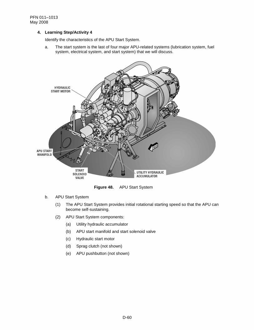
Figure 48. APU Start System
b. APU Start System
(1) The APU Start System provides initial rotational starting speed so that the APU can
become self-sustaining.
(2) APU Start System components:
(a) Utility hydraulic accumulator
(b) APU start manifold and start solenoid valve
(c) Hydraulic start motor
(d) Sprag clutch (not shown)
(e) APU pushbutton (not shown)
PFN 011–1013 May 2008
D-61
Figure 49. APU Start System Components
(3) APU Start System components description
(a) Utility hydraulic accumulator
1) The utility hydraulic accumulator stores hydraulic pressure for APU starting and emergency operation of the flight control system in the event of hydraulic systems failure.
2) The utility hydraulic accumulator is mounted on the aft equipment bay deck assembly, below the APU.
3) The utility hydraulic accumulator is a cylinder, wrapped with Kevlar® for
ballistic protection, composed of two internal chambers separated by a piston. One chamber stores hydraulic fluid at 3000 psi. The other chamber has a nitrogen gas precharge of 1650 psi at 70 °F.
NOTE: Detailed discussion of utility hydraulic accumulator operation is contained in the Hydraulics
System lesson.
(b) APU start manifold and start solenoid valve
1) The start manifold and start solenoid valve direct hydraulic pressure to the APU hydraulic start motor during an APU start.
2) The start manifold and start solenoid valve are attached to the forward end of the utility hydraulic accumulator.
3) The start manifold is a series of chambers encased in an aluminum manifold, with the start valve mounted internally.
PFN 011–1013 May 2008
D-62
4) The start solenoid valve is a normally closed valve energized open by the ECU during an APU start. After the APU NG reaches 60% the ECU will de-energize the start solenoid valve and engage the PTO clutch.
5) When the PTO clutch engages, it provides drive to the main transmission accessory gear train housing, which drives the utility hydraulic pump and recharges the accumulator to 3000 psi.
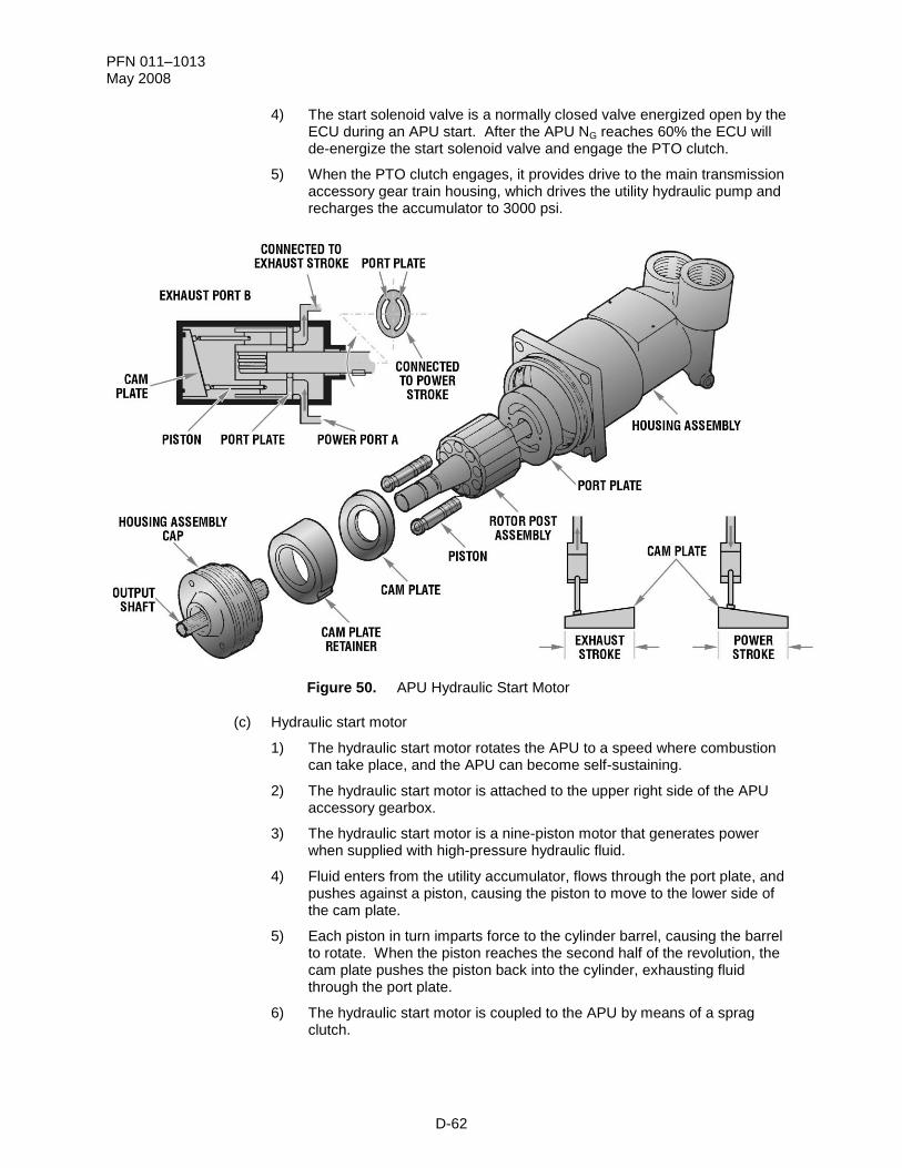
Figure 50. APU Hydraulic Start Motor
(c) Hydraulic start motor
1) The hydraulic start motor rotates the APU to a speed where combustion can take place, and the APU can become self-sustaining.
2) The hydraulic start motor is attached to the upper right side of the APU accessory gearbox.
3) The hydraulic start motor is a nine-piston motor that generates power when supplied with high-pressure hydraulic fluid.
4) Fluid enters from the utility accumulator, flows through the port plate, and pushes against a piston, causing the piston to move to the lower side of the cam plate.
5) Each piston in turn imparts force to the cylinder barrel, causing the barrel to rotate. When the piston reaches the second half of the revolution, the cam plate pushes the piston back into the cylinder, exhausting fluid through the port plate.
6) The hydraulic start motor is coupled to the APU by means of a sprag clutch.
PFN 011–1013 May 2008
D-63
Figure 51. Sprag Clutch
(d) Sprag clutch
1) The sprag clutch couples the starter with the gear train in order to drive the APU to a self-sustaining speed. It will decouple the starter when the APU becomes self-sustaining.
2) The sprag clutch is mounted in the accessory gearbox section, accessible by removing the hydraulic start motor.
3) When starter torque is applied to the inner race, the sprags move with a rolling cam action and, being larger than the space between the races, are wedged between them (engages the clutch). When the start solenoid is de-energized, the start motor begins to slow down, and the APU continues to accelerate. The outer race overruns the inner race, and the sprags roll out of engagement. As the outer race continues to increase in speed, centrifugal force moves the sprags away from the inner race.
PFN 011–1013 May 2008
D-64
Figure 52. APU Pushbutton
(4) APU pushbutton
(a) When the APU pushbutton is pressed, the SP initiates the start sequence by sending a command to ELC No. 2 to provided 24/28 Vdc to the ECU from the APU ECU PWR/START CB. The ECU energizes the hydraulic start solenoid valve, powering the APU start motor with 3000 psi hydraulic pressure from the utility accumulator.
(b) When the APU pushbutton is pressed a second time, the APU will shut down whether in the start sequence or fully operating.
PFN 011–1013 May 2008
D-65
Check On Learning
1. Is the magnetic chip detector connected to the warning, caution, and advisory system?
ACTION: Identify the Aircraft Subsystem Management (ASM) functions for the APU.
CONDITIONS: Given a written test utilizing the IETM without the use of student notes or references.
STANDARD: In accordance with TM 1-1520-251-10 and TM 1-1520-LONGBOW/APACHE IETM.
1. Learning Step/Activity 1
Figure 53. APU Block Diagram
a. APU Aircraft Subsystem Management (ASM)
(1) The basic control and monitoring of the APU is categorized as part of ASM. The
purpose of ASM is to reduce pilot workload, increase survivability, and increase
mission effectiveness. These goals are achieved by providing head-out operations,
automating control tasks, and integrating automated monitoring.
(2) APU power, start, and stop commands are processed by the SP. The SP monitors
the APU operation and will perform an APU shutdown under certain failure conditions.
b. APU ASM functions
(1) ELC No. 2 receives APU system commands from the SP and provides power to the
APU electrical loads. ELC No. 2 transmits APU load controller status to the SP via
the Multiplex (MUX) bus.
(2) Status transmittal and fault reporting
PFN 011–1013 May 2008
D-67
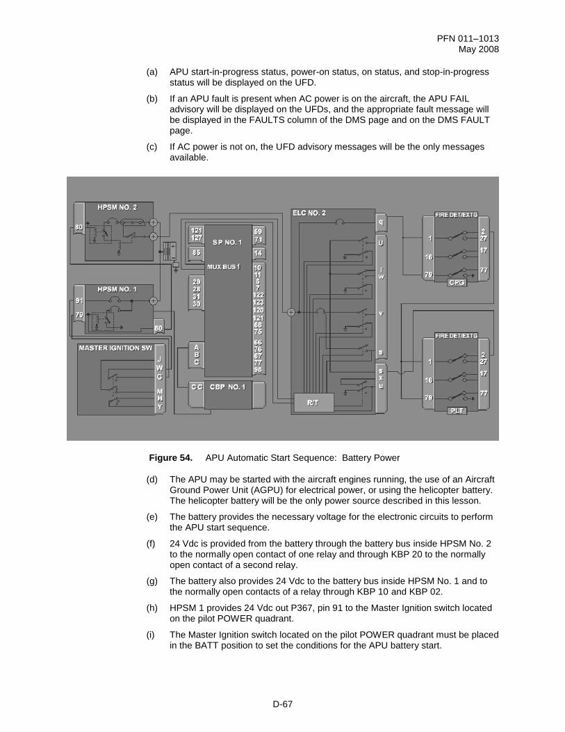
(a) APU start-in-progress status, power-on status, on status, and stop-in-progress status will be displayed on the UFD.
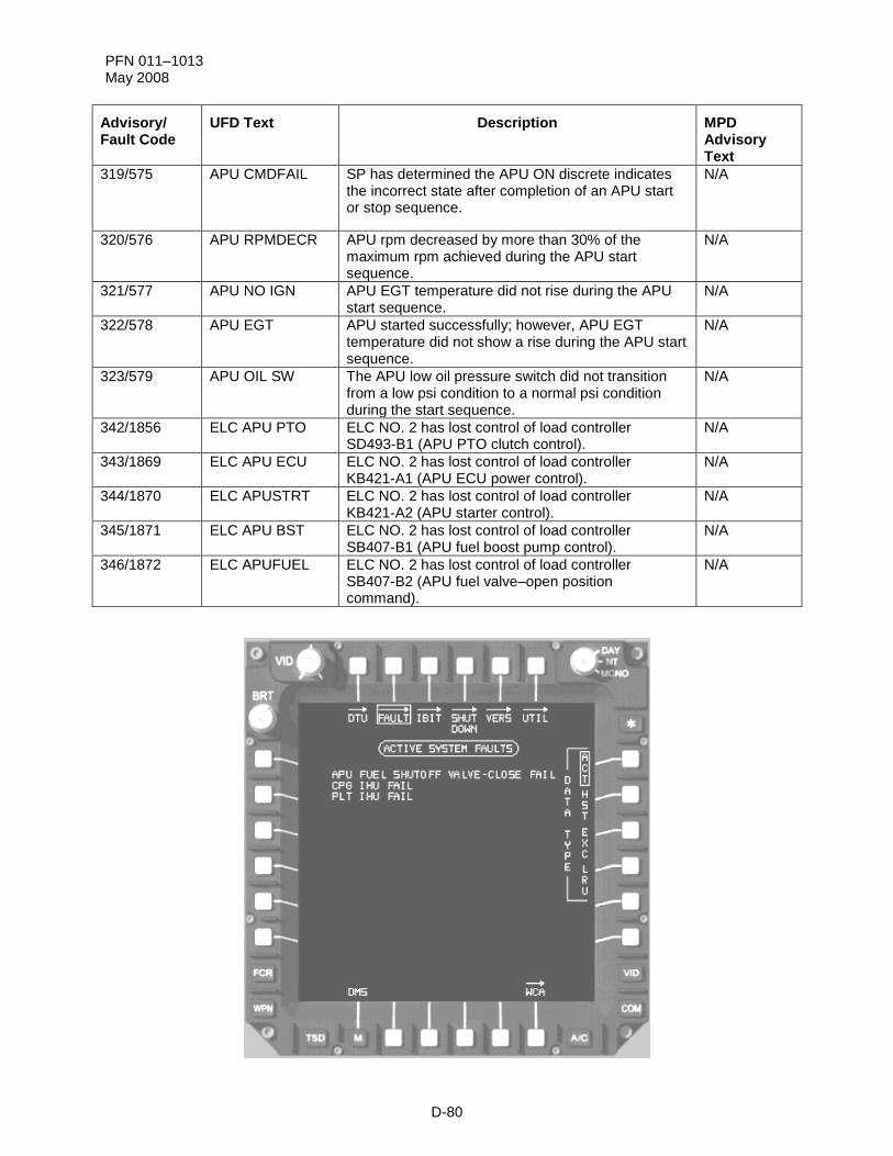
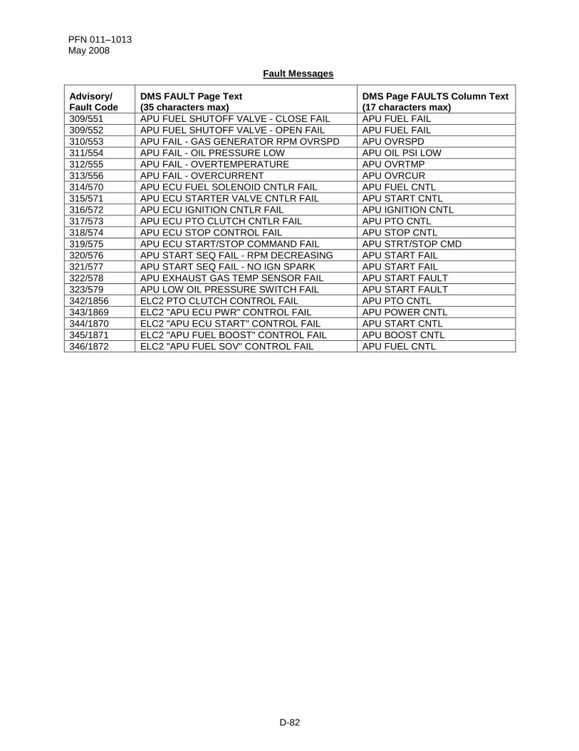
(b) If an APU fault is present when AC power is on the aircraft, the APU FAIL advisory will be displayed on the UFDs, and the appropriate fault message will be displayed in the FAULTS column of the DMS page and on the DMS FAULT page.
(c) If AC power is not on, the UFD advisory messages will be the only messages available.
Figure 54. APU Automatic Start Sequence: Battery Power
(d) The APU may be started with the aircraft engines running, the use of an Aircraft Ground Power Unit (AGPU) for electrical power, or using the helicopter battery. The helicopter battery will be the only power source described in this lesson.
(e) The battery provides the necessary voltage for the electronic circuits to perform the APU start sequence.
(f) 24 Vdc is provided from the battery through the battery bus inside HPSM No. 2 to the normally open contact of one relay and through KBP 20 to the normally open contact of a second relay.
(g) The battery also provides 24 Vdc to the battery bus inside HPSM No. 1 and to the normally open contacts of a relay through KBP 10 and KBP 02.
(h) HPSM 1 provides 24 Vdc out P367, pin 91 to the Master Ignition switch located on the pilot POWER quadrant.
(i) The Master Ignition switch located on the pilot POWER quadrant must be placed in the BATT position to set the conditions for the APU battery start.
PFN 011–1013 May 2008
D-68
(j) In the BATT position, 24 Vdc from the battery is supplied to the relay solenoid inside HPSM No. 1. The relay energizes and provides 24 Vdc to the logic circuits inside HPSM No. 1.
(k) The operating voltage closes the contactors inside the HPSM to allow 24 Vdc to the battery bus of Circuit Breaker Panel No. 1 (CBP No. 1) through internal wiring.
(l) CBP No. 1 provides 24 Vdc operating voltage to power SP No. 1.
(m) The SP provides the control and monitoring of the APU.
(n) The Master Ignition switch also provides 24 Vdc through HPSM No. 1 to HPSM No. 2. This 24 Vdc will power the logic circuits inside HPSM No. 2.
(o) The 24 Vdc at the relay solenoid inside HPSM No. 2 energizes the relay allowing 24 Vdc from the battery bus, through KBP 20, to the closed contacts of the relay to energize relay solenoid KB201. KB201 energizes, allowing 24 Vdc from the battery bus to be provided from HPSM No. 2 to ELC No. 2.
(p) ELC No. 2 contains the contactor to power the APU ECU, APU Fuel Boost pump (APU FUEL BST), and APU Fuel Shutoff Valve (APU FSOV) and provides the APU Start Command (APU START CMD).
(q) The APU ECU circuit breaker (KB421) on ELC No. 2 provides 24 Vdc to the normally open contacts of the START CMD and APU ECU switches.
(r) The 24 Vdc input to ELC No. 2 is provided through the APU BOOST & SOV circuit breaker (KB407) to the CPG and PLT Fire Detection and Extinguishing (FIRE DET/EXTG) panels normally closed contacts of the FIRE/READY switch. The 24 Vdc is returned to ELC No. 2 APU Fuel BST and APU FSOV switches.
(s) Should a fire occur while the APU is operating, selecting the APU Fire Ready switch in either crewstation will interrupt the voltage for the APU fuel boost pump and APU fuel shutoff valve causing fuel flow to the APU to stop.
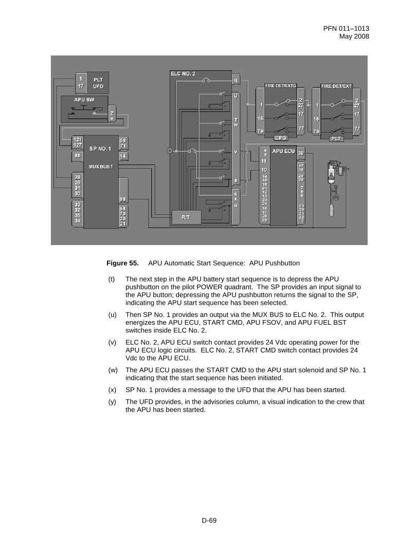
(t) The next step in the APU battery start sequence is to depress the APU pushbutton on the pilot POWER quadrant. The SP provides an input signal to the APU button; depressing the APU pushbutton returns the signal to the SP, indicating the APU start sequence has been selected.
(u) Then SP No. 1 provides an output via the MUX BUS to ELC No. 2. This output energizes the APU ECU, START CMD, APU FSOV, and APU FUEL BST switches inside ELC No. 2.
(v) ELC No. 2, APU ECU switch contact provides 24 Vdc operating power for the APU ECU logic circuits. ELC No. 2, START CMD switch contact provides 24 Vdc to the APU ECU.
(w) The APU ECU passes the START CMD to the APU start solenoid and SP No. 1 indicating that the start sequence has been initiated.
(x) SP No. 1 provides a message to the UFD that the APU has been started.
(y) The UFD provides, in the advisories column, a visual indication to the crew that the APU has been started.
(z) The energized ELC No. 2, APU FSOV switch provides 24 Vdc to the APU FSOV. The APU FSOV opens allowing fuel to be drawn from the aft fuel tank.
(aa) The energized ELC No. 2, APU FSOV switch provides 24 Vdc to the APU FSOV. The APU FSOV opens, allowing fuel to be drawn from the aft fuel tank. The 24 Vdc is returned to the SP, indicating that the APU FSOV has changed positions.
(bb) The energized ELC No. 2, APU FUEL BST switch provides 24 Vdc to the APU fuel boost pump.
(cc) The APU fuel boost pump begins to draw fuel from the aft fuel tank through the APU FSOV to the fuel solenoid valve.
PFN 011–1013 May 2008
D-71
Figure 57. APU Automatic Start Sequence: APU On
(dd) The 24 Vdc start command from the APU ECU energizes the APU start solenoid.
(ee) With the solenoid energized, hydraulic pressure from the hydraulic accumulator begins to rotate the APU hydraulic start motor, which rotates the APU shaft, thereby rotating the APU oil pump, increasing oil pressure inside the APU accessory gearbox.
(ff) The SP provides 24 Vdc through the APU ECU to the normally closed contacts of the LOP switch and back to the APU ECU until the oil pressure exceeds 90 psi. The APU ECU provides a ground for the 24 Vdc.
(gg) When the APU oil pressure reaches 90 psi, the LOP switch opens, removing the 28 Vdc back to the APU ECU. SP No. 1 will interpret this signal as a logic 1, indicating that the APU oil pressure is above 90 psi.
(hh) The APU ECU delays the LOP signal to the SP for 10 seconds to provide the oil pump time to raise pressure to 90 psi. If the APU oil pressure does not reach 90 psi within 10 seconds, the SP shuts down the APU start sequence. If the oil pressure exceeds 90 psi, the LOP switch opens, and the SP continues APU start.
(ii) The APU ECU provides a signal to the speed sensor monopole. As the hydraulic motor rotates the APU shaft, the APU speed sensor monopole senses the rotation and produces an output representing the APU rpm. The signal is routed back to the APU ECU.
(jj) When the APU rpm equals 5%, the APU ECU outputs a signal to the APU fuel shutoff solenoid, APU ignition exciter, and the SP. The APU fuel shutoff solenoid energizes, allowing the fuel pump to pass fuel, and the ignition exciter is energized.
PFN 011–1013 May 2008
D-72
(kk) Prior to APU ignition, the APU ECU outputs the APU ignition on and fuel solenoid status signal to the SP, notifying it that the APU ignition has occurred and the fuel solenoid is energized.
(ll) Fuel is passed to the atomizers, creating a fuel vapor fog inside the APU compressor. Simultaneously, the APU ignition exciter produces a high-voltage spark to ignite the fuel vapor and start the APU engine.
(mm) Once APU ignition has occurred, the APU ECU begins to monitor the APU EGT thermocouple for an overtemperature condition, the APU rpm for overspeed, and the APU for overcurrent conditions and reports the status to the SP.
(nn) As the speed of the APU shaft increases, the output of the APU monopole increases, producing an output signal representing the APU rpm. When the APU rpm reaches 60%, the APU ECU removes the APU START command, deenergizing the APU start solenoid and removing the pressurized hydraulic flow from the hydraulic start motor.
(oo) Also at 60% rpm, the APU ECU monitors the monopole sensor in the main transmission. If it is rotating at less than 95%, the APU ECU outputs a signal to the SP to energize the APU clutch solenoid. The SP outputs a signal via the MUX bus to the ELC to energize the PTO clutch switch.
(pp) The APU ECU outputs a signal through ELC No. 2, back through the APU ECU to the APU clutch solenoid. The solenoid energizes, operating the PTO clutch to connect the PTO shaft to the APU shaft. This connection rotates the main transmission accessory gearbox, which rotates the helicopter generators.
(qq) The utility hydraulic pump in the main transmission pressurizes the hydraulic accumulator.
(rr) As the APU rotates the APU shaft faster, the APU monopole outputs a larger signal representing the APU rpm. When the APU rpm is equal to 95%, the APU ECU removes the ignition exciter operating voltage and provides an APU ON signal to the SP.
(ss) The SP sends the UFD the APU ON message. The SP also sends a APU ON signal to the Lighting System Controller (LSC). The LSC provides a ground to illuminate the APU ON lamp on the pilot POWER quadrant. The APU ON lamp notifies the pilot that the APU is operating.
(tt) Also, with the APU at 95% rpm, the APU ECU outputs a signal through the CPG and pilot fire detection and extinguishing panels to energize the LCV. The LCV provides pressurized air for ground operations and engine start functions.
(uu) When the monopole output is equal to 100%, the APU ECU monitors the APU rpm, percent rpm, and EGT through a summing amplifier to provide an output to the torque motor. The torque motor controls the amount of fuel going through the APU fuel control, regulating the amount of fuel combustion, thereby controlling the speed of the APU.
(vv) The APU is now operating at 100% rpm. The SP and APU ECU continue to monitor the APU for failure conditions. If the APU has a failure, the SP or the APU ECU will remove power from the APU to shut it down.
(ww) With the solenoid energized, hydraulic pressure from the hydraulic accumulator begins to rotate the APU hydraulic start motor, which rotates the APU shaft, thereby rotating the APU oil pump, and increasing oil pressure inside the APU accessory gearbox.
(3) Normal APU shutdown
PFN 011–1013 May 2008
D-73
(a) When the APU pushbutton is activated for shutdown, the SP will perform the following:
1) Issue a discrete stop command to the APU ECU.
2) Command the ECU (through ELC NO. 2) to remove power to the APU boost pump and shutoff valve. If the ECU does not respond by closing the fuel shutoff valve solenoid, the SP will set the APU ECU STOP CONTROL FAIL fault, remove ECU power, and perform an APU shutdown due to failure.
3) Set the APU STOP advisory and clear the APU ON or APU START advisory.
(b) The SP will verify that the APU has shut down by monitoring the APU ON discrete signal from the ECU. If the APU ON direct input remains on after 5 seconds, the SP will set the APU ECU START/STOP CMD fault and perform an APU shutdown due to failure.
(4) APU shutdown due to failure
(a) Malfunctions causing automatic shutdown are as follows:
1) APU NG exceeds 108%.
2) Overtemperatures above 1785 °F (974 °C) up to 60%.
3) Overtemperature above 1340 °F (718 °C) at 100%.
4) Loss of temperature signal from thermocouple.
5) Low oil pressure.
6) Loss of APU speed sensor signal.
7) Overcurrent signal from the fuel control unit shutoff valve, igniter box, start solenoid valve, or PTO clutch solenoid valve.
(b) When the SP performs an APU shutdown due to a failure, it will perform the following:
1) Set the applicable failure indication
2) Set the APU STOP advisory
3) Send the APU stop command to the ECU
4) Remove ELC No. 2 power from the ECU
5) Command ELC No. 2 to close the fuel shutoff valve and turn off the APU boost pump
6) If the shutdown occurs during the start cycle, clear the APU PWR ON and APU START advisories
7) Verify the APU has shut down by monitoring the APU ON direct input. If the APU ON direct input remains on after 5 seconds, the SP will set the APU ECU START/STOP CMD fault.
(5) APU system fault monitoring
(a) The SP will monitor the following discrete and analog signals from the APU ECU to determine if the APU system is working properly.
(b) APU alarms
PFN 011–1013 May 2008
D-74
1) Four seconds after the SP verifies that the ECU is powered, and until the APU is commanded off or shut off, the ECU is monitored for overspeed, low oil pressure, overtemperature, and overcurrent.
2) If any of these occur, the SP will perform an APU shutdown due to failure.
(c) APU ON discrete
1) The SP will continually monitor the APU ON direct input from the APU ECU to verify the APU is on.
(d) APU fuel shutoff valve
1) The SP verifies that the APU fuel shutoff valve is in the commanded state by monitoring the APU FUEL SOV OPEN or APU FUEL SOV CLSD direct status input for the corresponding command.
(e) APU ECU STOP CONTROL FAIL fault and start sequence faults
1) The requirements for setting these faults are listed in the troubleshooting ELO.
(f) APU ELC NO. 2 faults
1) The requirements for setting these faults are listed in the troubleshooting ELO.
PFN 011–1013 May 2008
D-75
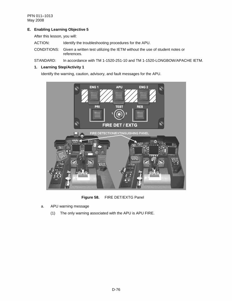
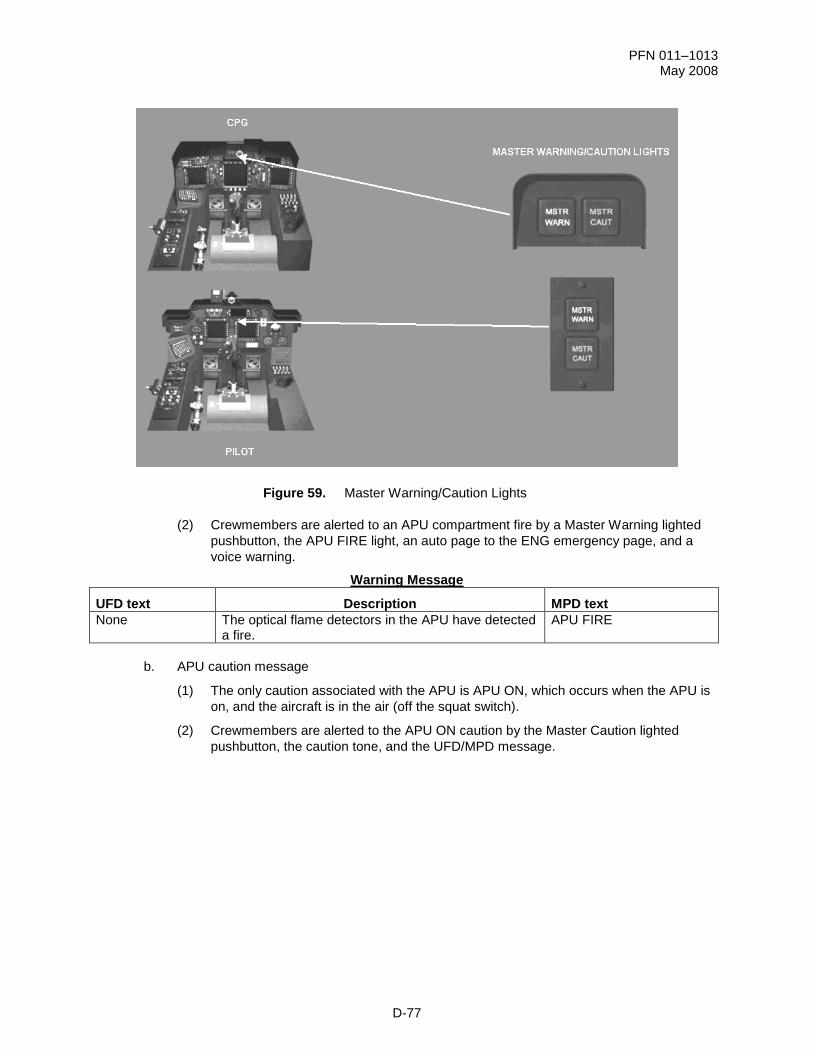
Check On Learning
1. Which ASM component processes the APU power, start, and stop commands?