United States Department of the Interior Bureau of Reclamation Engineering and Research Center Translation No. : 2 }ilJ Team No.: . General Book No: 12,943 HYDRAULICS BRANCH OFFICIAL FILE COPY xxxxxxxxxxxxxxxxxxxxxxxxxxxxxxxxxxxxxxxxxxxxxxxxxxxxxxxxxxxxxxxxxx FLOW AND ENERGY DISSIPATION IN GABION STEPPED WEIRS Ecoulement et dissipation sur les deversoirs en gradins de gabions by L. Peyras, P. Royet, G. Degoutte from LA HOUILLE BLANCHE NO. 1-1991 Translated by Jean-Claude Arteau xxxxxxxxxxxxxxxxxxxxxxxxxxxxxxxxxxxxxxxxxxxxxxxxxxxxxxxxxxxxxxxxxx Division of Foreign Activities Code D-2000 USBR Translations Denver, Colorado August, 1991
Transcript
United States Department of the Interior Bureau of Reclamation Engineering and Research Center
Flow and energy dissipation in gabion stepped weirs
L . Peyras, P. Royet, G. Degoutte
ABSTRACT. Gabions are commonly used for building small dams in the Sahel region of Africa; gabion weir technology is widespread in flood spillways. In addition to good mechanical stability and a high level of resistance to flood flows, a gabion weir dissipates large amounts of energy above the stilling basin. Nevertheless, the optimum dimensions for this type of structure are not yet well defined. In order to quantify the energy dissipated on the steps of such structures, a systematic study of standard spillways 3 to 5 m high, with flowrates up to 3 m3 .s-1 .m1-1
, has been carried out on a 1:5 scale model.
The energy dissipation has been quantified and the dimensioning parameters of the stilling basin have been determined. The test results led to a 10 to 30 % reduction of the stilling basin length compared to the methods previously used. The study also attempted to characterize flow over steps and define the phenomena observed during the different hydraulic regimes.
Introduction
G~bions remain the preferred material for buiding hydraulic structures. Especially in the Sahel region of Africa, the social, economic and technical contexts are such that gabions are commonly used for building small earth dams. The design of these dams is relatively standard; in particular, gabions are commonly used in flood spillways. As a matter of fact, gabion spillways offer a solution which is often selected. These weirs are characterized by good mechanical stability, high resistance to flood flows and relative ease of construction.
Nevertheless, the rules for dimensioning this type of weir are not well established, especially the length of the stilling basin. The existing literature on gabion structures at best proposes methods similar to those applied to smooth inclined weirs [3] or to straight drop weirs [l]. The analytic methods provided do not take into account the energy dissipation due to the stepped profile, and lead to oversized stilling basins. Only STEPHENSON has run tests on gabion stepped sills at the 1:10 scale [9]. However, the scale models were less than 4 m in height and involved infiltration through the upstream facing, thus restricting the application of the test results to permeable sills in streams.
Because of the complexity of flow over stepped surfaces and within the gabions themselves, analytic methods such as numerical modelling are hard to apply and scale models remain the preferred method of investigation. Many stepped weirs have been tested,
1
mainly in connection with large concrete dams infiltration phenomena are excluded and transient regimes, basic to our study, are negligible [4], [8].
for which hydraulic
For these reasons, we carried out scale model testing in order to observe flow over small weirs with steps of uniform height, in order to quantify the energy dissipation over "standard" gabion stepped weirs and to establish the dimensioning parameters for the stilling basin. Finally, we attempted to analyse gabion deformation and some problems related to the durability of structures during floods.
Scale model testing
Scale models
The 1: 5 scale used was sufficiently large to approximate closely the actual hydraulic phenomena and minimize similitude and measurement errors. The gabions used in the model were exactly at the 1:5 scale, i.e. geometric dimensions of 20 cm x 20 cm x 60 cm (actual gabions of 1 m x lm x 3m), hexagonal wire mesh of 20 mm x 30 mm (actual 100 x 120 mesh type) and 0.7 mm wire diameter (3.5 mm actual diameter), and filling aggregate (30 to 40 mm ballast). The terminology and uni ts used in this paper are described in the appendix.
Testing was carried out in the 80 cm wide glass-enclosed canal of the Societe du Canal de Provence. The simulated flowrates (10 per test) ranged from O. 5 to 3 m3
• s -1• m1-1
• Only the downstream dam facing was reproduced; the upstream facing was replaced with a waterproof membrane.
We tested energy dissipation on weirs having the following characteristics (fig.l):
- downstream facing slopes of 1:1, 1:2 and 1:3; - weir heights of 3, 4 and 5 m, i.e. 3, 4 and 5 steps
respectively (standard step height of 1 m).
Different stepped profiles were reproduced (fig. 2):
- gabion steps or "bare" gabions; - steps with a tread protected by a horizontal concrete
slab; the "concrete slab" technique is recommended when floodwaters are loaded with sediments;
- steps with a tread protected by a "counter-sloped" concrete slab;
- steps with a nose having a "counter-sill" made of a flat gabions.
2
The flow of water over surface weirs is characterized by high velocities. The gravitational force dominates all other external forces, allowing Froude' s similitude to be used. All results correspond to the 1:1 scale.
Instruments
The specific loads at the weir toe were measured with a Pitot ramp, i.e. a series of Pitot tubes placed along a cross-section and connected to the same reading tube. This ramp, a copper tube with small openings facing the flow lines, integrates the specific load (II,) over a weir section. As opposed to a Pitot tube which would record all flow variations at a specific point of the section, the Pitot ramp gives stable readings of (Ii,). An accurate calibration of the ramp gave a default error between 6 and 10 % depending on the flowrate; the test results were correspondingly increased.
The flowrate of the water entering the glass-enclosed canal was measured with a standard thin-walled triangular weir. Volume measurements have shown the flowrate error to be less than 3 %.
Testing methodology
The total initial head of the flow over the sill (E0) is calculated in the critical section, from the flowrate:
[Formula]
H weir height Ye critical depth; Ye= (q
2/2g)
113, with q the flow rate per unit of
sill length (in m3 .s-1 .m1-1).
The residual head (E1) at the weir toe (at the stilling basin entrance, upstream of the jump) is measured with the Pitot ramp. The head loss E0 - E1 can then be calculated.
Flow over steps
Testing has shown two flow types: nappe flow and skimming flow.
Nappe flow
Nappe flow is observed for low to medium flowrates. The overflowing sheet of water strikes the tread of the next lower step, totally first (free nappe) and then partially (partial nappe).
Free nappe flow
Two hydraulic regimes are possible, one characterized by the alternation of f luvial and torrential regimes, and the other
3
exclusively torrential.
a. Alternation of fluvial and torrential regimes: an hydraulic jump begins just downstream of the striking point of the overflowing sheet of water. This type of flow has been observed only for counter-sloped or counter-silled profiles and for low flowrates ( lower than 1 m3 • s -1 • ml-1).
A simple model can be proposed for this particular case, which correlates well with our test results (fig. 3):
- at the striking point of the overflowing sheet of water, the flow has a minimal depth Y1 • Under the sheet of water, at the foot of the step, a water cushion forms, with a depth YP;
- the jump starts in section 1;
- just downstream of the jump in section 2, the flow becomes fluvial, with the depth Y2 ;
- between section 2 and section 3, the flow speeds up because of the drop, becomes torrential again and takes the critical depth Ye in section 3.
The hydraulic conditions are identical from one step to the next; for each step, the flow dissipates an amount of energy equivalent to its height. We can then propose an energy dissipation formula for stepped weirs and free nappe flow:
----------> Flow direction
2m 1-----l
--~ r,m . . I1m
;:i-<XK>· -<:><· CM· I 1 m
m Gabiona
1m
1. Example of a downstream stepped facing made of gabions (height 4 m and slope 1:2), with the gabion-lined stilling basin at the weir toe.
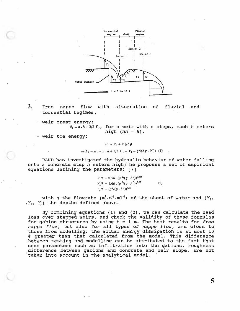
3. Free nappe flow with alternation of fluvial and torrential regimes.
- weir crest energy: £0 = n . h + 3/2 Y Cf for a weir with n steps, each h meters
high (nh = H). - weir toe energy:
£ 1 = Y1 + V ~/2 g
= £ 0 - £ 1 = n . h + 3/2 Y e- Y1 - {//(2t: , Y~) ( I)
RAND has investigated the hydraulic behavior of water falling onto a concrete step h meters high; he proposes a set of empirical equations defining the parameters: [7]
Y1/h = 0,54 • (q "/ ( g • h 3))0,425
Y2/h = 1,66. (q 2/ (g . h 3))°'27 (2)
YP/h = (q 2/ (g . h 3))0.22
. with q the flowrate (m3 .s-1 .m1-1 ) of the sheet of water and (Yu . Y2, YP) the d epths defined above.
By combining equations (1) and (2), we can calculate the head loss over stepped weirs, and check the validity of these formulas for gabion structures by using h = 1 m. The test results for free nappe flow, but also for all types of nappe flow, are close to those from modelling: the actual energy dissipation is at most 10 % greater than that calculate d from the model. This difference between testing and modelling can be attributed to the f a ct that some parameters such as infiltration into the gabions, roughness difference between gabions and concrete and weir slope, are not taken into account in the analytical model.
5
(A)
(B)
6
(C)
(D)
• 7
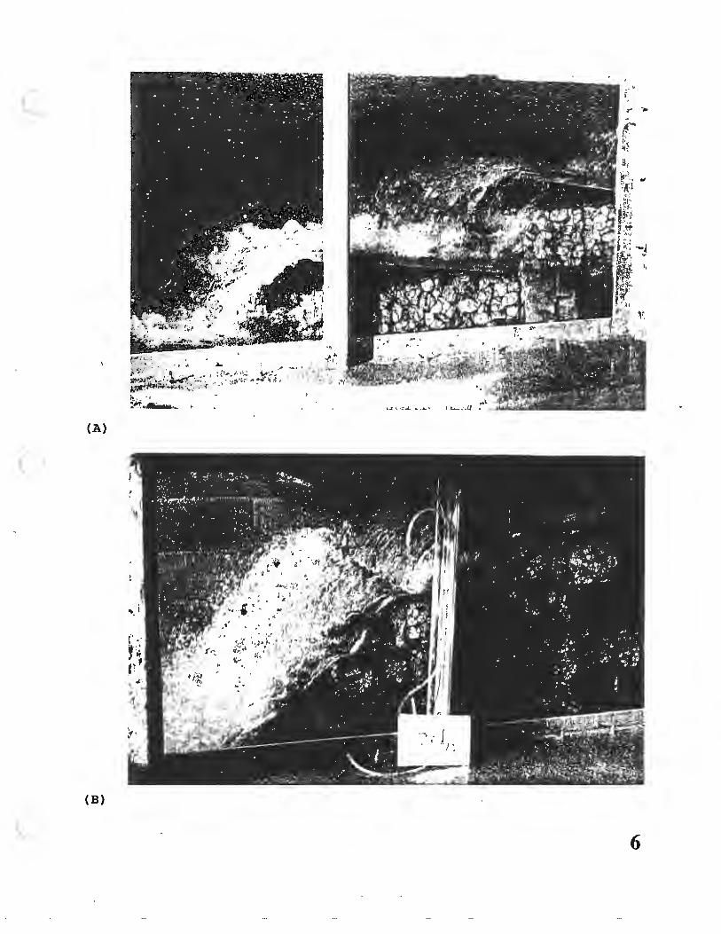
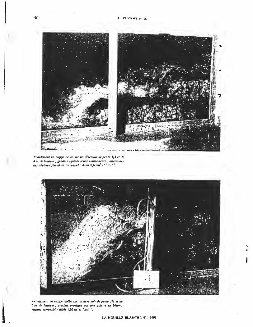
A. Free nappe flow: over a weir of slope 1: 3 counter-sloped steps; alternation of fluvial regimes; flowrate of 0.60 m3 .s-1 .m1-1
•
and height 4 m,· and torrential
B. Free nappe flow over a weir of slope 1:1 and height 5 m; steps with concrete slab protection; torrential regime; flowrate of 1.03 m3 • s -1 .m1-1 •
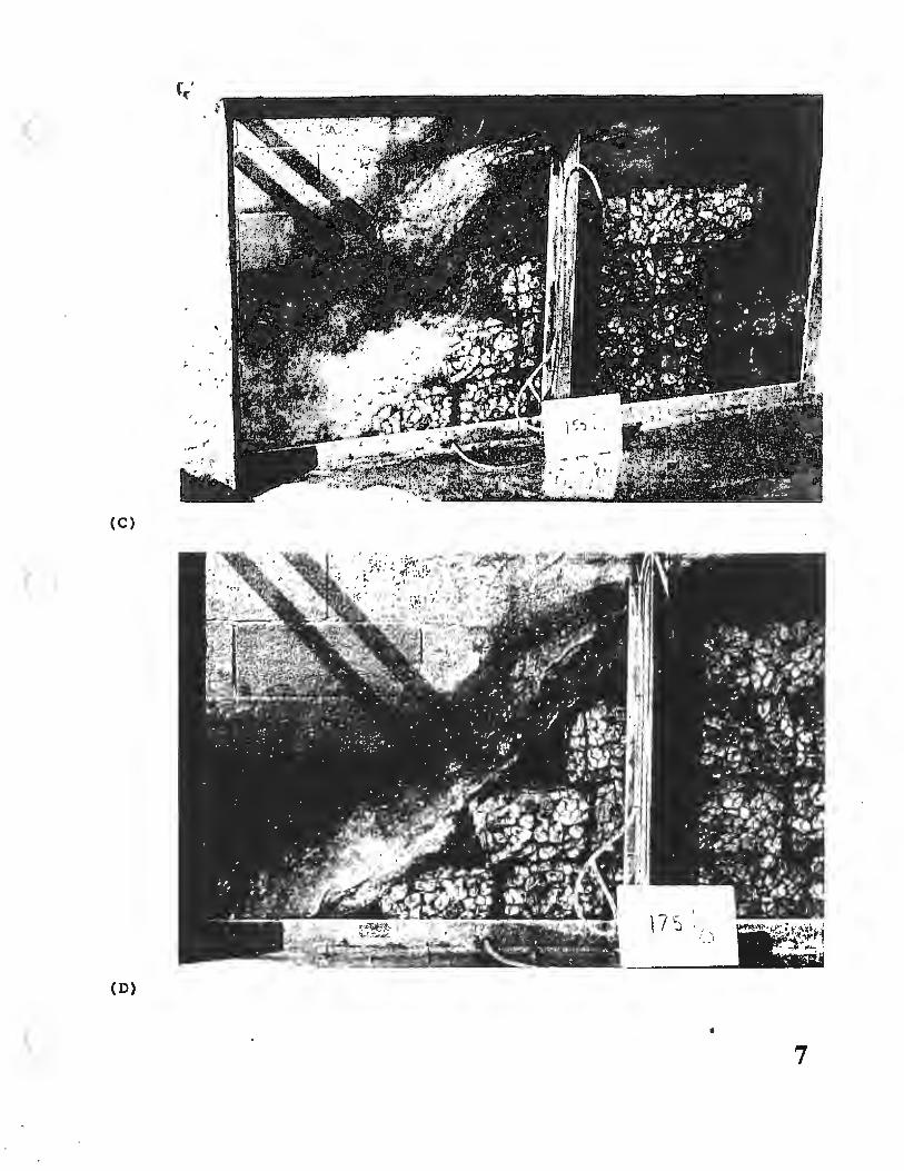
C. Skimming flow over a weir of slope 1:1 and height 5 m; steps of "bare" gabions; torrential regime; flowrate of 2.17 m3 .s-1 .m1-1 •
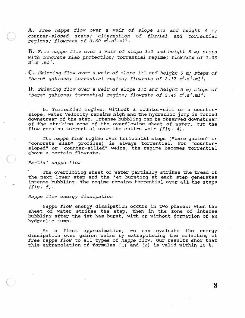
D. Skimming flow over a weir of slope 1:1 and height 5 m; steps of "bare" gabions; torrential regime; flowrate of 2.45 m3 .s-1 .m1-1 •
b. Torrential regime: Without a counter-sill or a counterslope, water velocity remains high and the hydraulic jump is forced downstream of the step. Intense bubbling can be observed downstream of the striking zone of the overflowing sheet of water, but the flow remains torrential over the entire weir (fig. 4).
The nappe flow regime over horizontal steps ("bare gabion" or "concrete slab" profiles) is always torrential. For "countersloped" or "counter-silled" weirs, the regime becomes torrential above a certain flowrate.
Partial nappe flow
The overflowing sheet of water partially strikes the tread of the next lower step and the jet bursting at each step generates intense bubbling. The regime remains torrential over all the steps (fig. 5).
Nappe flow energy dissipation
Nappe flow energy dissipation occurs in two phases: when the sheet of water strikes the step, then in the zone of intense bubbling after the jet has burst, with or without formation of an hydraulic jump.
As a first approximation, we can evaluate the energy dissipation over gabion weirs by extrapolating the modelling of free nappe flow to all types of nappe flow. our results show that this extrapolation of formulas (1) and (2) is valid within 10 %.
8
4. Free nappe flow with constant torrential regime
5. Partial nappe flow
6. Skimming flow
liait q
2 ,5
Turbulence
Velocity build-up phaae; floY without turbulence
Air entrainment; zone or intanae bubbling
• Teat point•
Skimming flow
1 ,5
113 .___________,,2 -.-~------------~"'
Nappe f low
0,5
Slope i
0 , 3 0,4 0 , 5 0,6 0, 7 0 , 8 0 , 9
7. Limit unit flowrate q (m3/s/ml) between nappe and skimming flows, as a function of slope i (m /m ) for stepped weirs made of "bare" gabions.
9
Skimming flow
Skimmi ng flow was observed for average to high flowrates; the sheet of water is not visible and the weir is totally submerged in a fast and relatively smooth current.
From upstream to downstream, two zones can be identified (fig. 6) :
- A first transient zone over the first two steps; the flow accelerates until it reaches the maximum limit velocity Vmu for which air entrainment begins; there is no bubbling during this velocity build-up phase and the upper surface of the flow is smoothly undulated over the weir.
- The flow reaches the limit velocity Vmu for which air entrainment begins. Air particles mix with the stream of water and intense bubbling develops down to the weir toe. The water cushion at the foot of each step is replaced by a ground roller showing the rotation of entrained air bubbles; the stream of water moving along the weir is supported by the ground rollers and the noses of steps.
The onset velocity of air entrainment depends only on the weir characteristics, especially step height (h = 1 min this case) and tread width. Whatever the flowrate of the simulated flood (up to 3 m3 .s-1 .m1-1
), the measured values of Vmax ranged from 5.5 to 6 m/s depending on weir slope. When Vmax was attained, th·e water velocity decreased slightly; in addition to losing h meters of potential energy per step, the flow also dissipated some of its kinetic energy.
RAJARATNAM proposes a skimming flow model based on tests carried out by SORENSEN [6], [8].
Boundary between nappe and skimming flows
. Skimming flow develops for flowrates higher than those of nappe flow. The geometrical characteristics of the steps are definitely a factor in the onset of air entrainment: a steep slope and horizontal steps are condusive to skimming flow. Figure 7 shows the boundary between the two flow regimes.
Energy dissipation over gabion weirs
Dimensionless presentation of the results
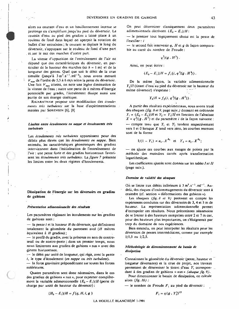
The parameters controlling flow over gab ion steps are the following:
10
the weir slope i and height H, sole determinants of the downstream facing geometry (H meters are equivalent to H steps);
- the step profile, with or without counter-sill or counter-slope; initially, we will only consider "bare" gabion steps with horizontal treads;
- the flowrate per unit of length which, together with the slope i, determines the flow type (nappe or skimming);
the gravitational force which dominates all other external forces.
For "bare" gabion steps, four parameters are necessary to completely express the dimensionless variable (E0 - E 1 ) / H (head loss per unit of weir height):
(f/0 - E,)/H = f(q, H, i, g )
Using traditional methods, we can determine two dimensionless parameters describing (E0 - E1 )/H:
- the first is obviously the slope i of the stepped weir;
- the second combines q, Hand gin a way comparable to the square of Froude's number:
q2/ (g . H J) .
The following relation can thus be written:
In the same way, the dimensionless variable Ytf H (weir toe depth over weir height) is written as follows:
Y, /H = / 2(i, q 2/ (g. HJ)).
Test results are represented by graphs (figs. 8 and 9) in the coordinates systems [Yl = (E0 - E1) /H; X = q 2
/ (g.H3)] and [Y2 = Y1/H;
X = q 2 /(g.H3 )] respectively, for different values of i:
- considering that Y1 and Y2 approach 1 and O respectively when X approaches O, the curves under consideration are of the form:
- these curves are fitted to the test results by using the least square method after a logarithmic transformation.
11
The best-fit coefficients are provided in tables I and II.
Table I Rela t i onship between Yl = (E0 - E1)/H and X = q2/(g.H3
) in the form 1/( 1 - Y,) =a,. X b' ; best-fit coefficients a 1 and b 1; coefficient of deter mi nation r 2.
Only flowrates of less than 3 m3 • s-1. m1-1 are considered, since the weir could be damaged by higher flowrates (see the "gabion deformation" section).
The graphs (figs. B and 9) represent tests carried out on weirs 3, 4 and 5 m high. The dimensionless representation allows us to extrapolate these results. We nevertheless recommend restricting extrapolation to heights between 2 and 7 m, in order not to deviate too much from our test range.
The results can nevertheless be interpolated for weirs with slopes between those we experimented with, 1: 1. 5 or 1: 2. 5 for example.
Methodology for dimensioning the stilling basin
Knowing the weir geometry (slope, height and spilling length) and the flood parameters of the project, this study allows us to determine the depth Y1 corresponding to "bare" gabion steps (graph of fig. 9)
12
(E O·E1 )ili
0 ,9
0,8
0,7
0,6
0,5
0,4
0,3
0,2
0, 1
0
0,0001
,.._ "= -- -J l t:£>~:+L -~=c :::1:: 6 A
n----f-~ -- 6 .- ' -o n - -r . 'J t:,',
I 0 -- -t· '
r ~
L
p
L
0,001
0 Slope l: l 6 slope l : 3
I I
i I
I !} ~ ' ~/ ',4
' ' ' i' ~ '6. ' ' ' 0#' '
'o"" ' [ ' .-.c •t..
- 'D \ '{_ - '.Ju •, \
\' \~ \
\
\ 0 1/3 \ I \ \
\ I \ 1/2
I
1/1
0,01
• Slope l: 2
8. Unit head loss over a stepped weir made of "bare" gabions
Y1/H
0, 18
0, 16
0, 14
0, 12
0, 1
0,08
0,06
0,04
0,02
0
0,0001
---- "--- _[ --
I -~ _,, -.. - -'S -.:. -· 0 ,- -:1 Q
-tr :. :d -- ...- C
- • - ,_. ·--D ::: -[ b
0,001
0 Slope l: l 6 Slope 1:3
/ / v
£• •o /
,,. ,,( /
/t ,-[), /
/ -,, /
,: ..:-~: ;9 )'
A .-u /
::r - ;i/ -::_H /
,, D
~ r ][
0,01
+ Slope 1:2
9. Depth Y1 at the toe of a weir made of "bare" gabions
I 1/3
I
1/2
1 /1
I
I
0,1
0, 1
13
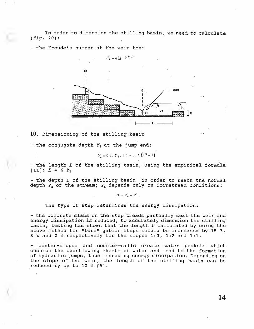
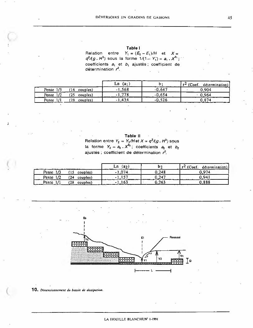
In order to dimension the stilling basin, we need to calculate (fig. 10):
- the Froude's number at the weir toe:
Io t---- L
10. Dimensioning of the stilling basin
- the conjugate depth Y2 at the jump end:
- the length L of the stilling basin, using the empirical formula [11]:L=6Y2
- the depth D of the stilling basin in order to reach the normal depth Yn of the stream; Yn depends only on downstream conditions:
The type of step determines the energy dissipation:
the concrete slabs on the step treads partially seal the weir and energy dissipation is reduced; to accurately dimension the stilling basin, testing has shown that the length L calculated by using the above method for "bare" gabion steps should be increased by 15 %, 8 % and O % respectively for the slopes 1:3, 1:2 and 1:1.
center-slopes and counter-sills create water pockets which cushion the overflowing sheets of water and lead to the formation of hydraulic jumps, thus improving energy dissipation. Depending on the slope of the weir, the length of the stilling basin can be reduced by up to 10 % [5].
14
Discussion
The head loss per unit of height (E0 - E1)/H decreases sharply when q2/(g.H3
) increases and thus, for H constant, when the flowrate increases. This phenomenon is explained by the change of regime (from nappe flow to skimming flow) which occurs when q2
/ (g.H3 )
increases. The energy dissipated by skimming flow is much lower than that of nappe flow.
We also see that the graphs of variables (E0 - E1 )/H and Y1/H for various slopes tend to merge when q2
/ ( g. H3) ( and thus q)
decreases. As was shown for the modelling of free nappe flow, the same hydraulic conditions exist for each step, independently of the weir slope.
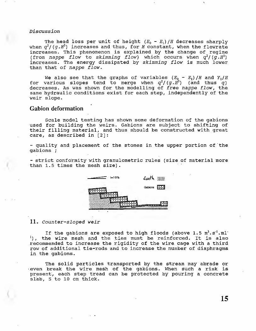
Gabi on deformation
Scale model testing has shown some deformation of the gabions used for building the weirs. Gabions are subject to shifting of their filling material, and thus should be constructed with great care, as described in [2):
- quality and placement of the stones in the upper portion of ·the gabions;
- strict conformity with granulometric rules (size .of material more than 1.5 times the mesh size).
i-10%
Gabions m
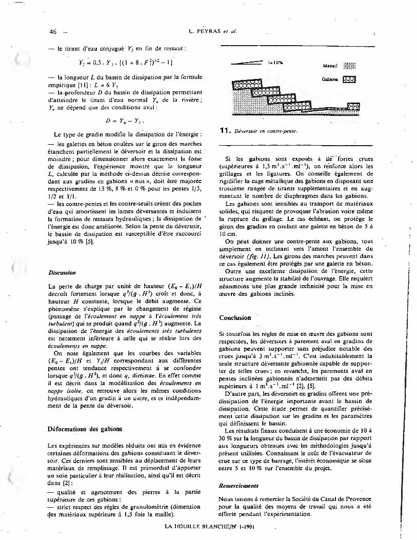
11. Counter-sloped weir
If the gab ions are exposed to high floods ( above 1. 5 m3 • s -1 • ml-1), the wire mesh and the ties must be reinforced. It is also recommended to increase the rigidity of the wire cage with a third row of additional tie-rods and to increase the number of diaphragms in the gabions.
The solid particles transported by the stream may abrade or · even break the wire mesh of the gabions. When such a risk is present, each step tread can be protected by pouring a concrete slab, 5 to 10 cm thick.
15
The gabions can be counter-sloped simply by tilting the entire weir in the upstream direction (fig. 11). In that case, the step treads can also be protected by concrete slabs.
In addition to increasing energy dissipation, this type of facing increases the overall stability of the structure. It nevertheless requires more sophisticated technical means to place the tilted gabions.
Conclusion
Provided the construction rules are respected, weirs with a stepped downstream facing made of gabions can withstand floods up to 3 m3
• s-1• m1-1 without noticeable damage. This is without any doubt
the only gabion spilling structure capable of withstanding such floods; on the other hand, sloped downstream facings made of gab ions cannot withstand floods in excess of 1 m3
• s -1• m1-1
[ 2 J, [ 5 J.
Moreover, stepped weirs induce a high level of energy dissipation above the stilling basin. This study has shown how to quantify this dissipation over the steps and to establish the parameters of the basin.
The final results lead to a 10 . to 30 % reduction of the stilling basin length in comparison with traditional methods. Knowing the cost of the flood spillway on this type of dam, the savings amount to 5 to 10 % of the project cost.
Acknowledgmen'ts
We wish to thank the Societe du Canal de Provence for the valuable help which was provided during the experimental work .
16
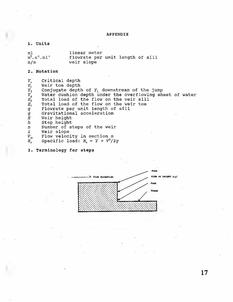
1. Units
ml linear meter
APPENDIX
m3 • s-1 • m1-1
m/m flowrate per unit length of sill weir slope
2. Notation
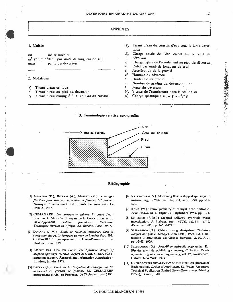
~ Critical depth Y1 Weir toe depth Y2 Conjugate depth of Y 1 downstream of the jump YP Water cushion depth under the overflowing sheet of water E0 Total load of the flow on the weir sill E1 Total load of the flow on the weir toe q Flowrate per unit length of sill g Gravitational acceleration H Weir height h Step height n Number of steps of the weir i Weir slope Vm Flow velocity in section m H, Specific load: H. = Y + V 2/2g
3. Terminology for steps
110 ..
-----> Flow diraction Sida or baigbt :eur
root
Traad
17
References
[l] AGOSTINI R., BIZARRI A., MASETTI M.: Ouvrages flexibles pour tronc;ons torrentiels et f luviaux ( 1re partie : Ouvrages transversaux) . [ Flexible structures for torrential and f luvial sections (First part: Transverse structures).] Ed. France Gabions s.a., Le Pouzin, 1987.
[2] CEMAGREF: Les ouvrages en gabions. [Gabion structures.] In the course of publication by the French department of cooperation and development. Previous publication: Collection Techniques Rurales en Afrique. [Series on Rural Techniques in Africa.] Ed. Eyrolles, Paris. 1974.
[3] DURAND J.-M.: Etude de variantes techniques dans la conception des petits barrages en terre au Burkina Faso. [Study of technical alternatives for small earth dams in Burkina Faso.] Ed. CEMAGREF, Aix-en-Provence Group, Le Tholonet, May 1989.
[ 4] ESSERY s .. HORNER W. : The hydraulic design of stepped spillways (CIRIA Report 33). Ed. CIRIA (Construction Industry Research and Information Association), London, January 1978.
[ 5] PEYRAS L.: Etude de la dissipation de l 'energie sur les deversoirs en gradins de gabions. [Study of energy dissipation on stepped weirs made of gab ions. J Ed. CEMAGREF, A ix-en-Provence Group, Le Tholonet, May 1990.
[6] RAJARATNAM N.: Skimming flow in stepped spillways. J. hydraul. eng. ASCE, vol. 116. no. 4, April 1990, pp. 587-591.
[7] RAND W.: Flow geometry at straight drop spillways. Proc. ASCE, 81 E, Paper 791, September 1955, pp. 1-13.
[8] SORENSEN R.M.: Stepped spillway hydraulic mode investigation. J. hydraul. eng., ASCE, vol. 111. No. 12, December 1985, pp. 1461-1472.
[9] STEPHENSON D.: Gabion energy dissipators. Thirteenth Congress on Large Dams. New-Delhi, 1979. Ed. International Commisiion on Large Dams, Q. 50, R. 3, pp. 33-43, 1979.
[ 10 J STEPHENSON D. : Rockfill in hydraulic engineering. Ed. Elsevier Scientific Publishing Company, Developments in Geotechnical Engineering Series, vol. 27, Amsterdam, Oxford, New York, 1979.
[11] UNITED STATES DEPARTMENT OF THE INTERIOR (Bureau of Reclamation). Design of small dams. Ed. Water Resources Technical Publication (United States Government Printing Office), Denver, 1987.
18
TrinslalDr· ~ ~~'.ud ThiS ,:nate;ial may be protected/ Dy Due Data- -8 -:;, 0 _~ 1 copyright law (Title 17'-_ U.S. Cdde). Tra~~·-; Team No.~
Book No. 1 .2 /I It 3
Ecoulement et dissipation sur les deversoirs en gradins de gabions
L. Pcyras, P. Royet, G. Dcgouttc*
Introduction
Les gabions demeurent des materiaux privilegies dans la realisation d 'ouvrages hydrauliques. En Afrique Sahelicnne notamment, le contexte social, economique et technique rend leur utilisation courante dans !es petits barrages en terre. Ces retenues sont de conception relativement standardisee ; en particulier, on emploie usucllcment !es gabions d,ms !es evacuatcurs de crue . A cet egard, !es evacuateurs en gradins de gabions sont une solution frequemment adoptee. Ces structures deversantes presentenl une grande stabilite mecanique ainsi qu'une bonne resistance au deferlement de crues; en outre, leur mise en a:uvre est aisee.
Cependant, Jes regles de dimensionnement de ce type de deversoirs sont ma! etablies, en particulier en ce qui concerne la methode de calcul du bassin de dissipation. Dans l'etat actuel des connaissances, les manuels traitant d'ouvrages en gabions proposent au mieux des methodologies analogues a celles utilisees pour !es deversoirs en pentes inclinees sans gradins [3], ou pour !es deversoirs en chute verticale [!). En aucun cas !es calculs mentionnes ne prennent en compte la pre-dissipation qu'offre la structure en marches d'escalier, si bien que le bassin de dissipa tion est largement surdimensionne. Seu! STEPHENSON a experimente des seuils en gradins de gabions a l'echelle 1/10 [9]. Cependant, !es
modeles testes n'excedent pas 4 m de hauteur, et surtout, ils font intervenir des infiltrations a travers le parement amont, ce qui limite l'applicaiion de ses resultats aux seuils permeables en ·riviere.
Devant la complexite des ecoulements sur Jes gradins et au sein des gabions, des me'thodcs de calcul telles que la modelisation numerique sont difficilement applicables et Jes modeles reduits restent l'outil privilegie. De nombreux devcrsoirs en gradins ont fait l'objet d 'experimentations. Elles concernent essentiellement les grands barrages en beton, ou Jes phenomenes d'inliltrations sont exclus et ou !es regimes hydrauliques transitoires, fondamentaux dans notre etude, sont negligeables [4], [8].
Nous avons done realise une experimentation sur modeles reduits afin d'observer les ecoulements sur des petits deversoirs en marches d'escaliers homogenes, de <.Juantifier precisement la dissipation de I'energie sur Jes dewrsoirs « standards » en gradins de gabions, et d'etablir les parametres qui determineront le bassin de dissipation. Entin, nous nous sommes auaches a analyser !es deformations des gabions et !es problemes lies a la perennite de l'ouvrage lors du passage des crues.
• CEMAGREF, groupement d'Aix-en-Provence, B.P. 31 , Le Tholonet , 1361 ~ Aix en Provence Cedex I, Ti:l. : 42 66 93 10.
Flows and dissipation of energy on gabion weirs
The use of gabions in the small dams in !he Sahel regions of Africa is quite common, they are used in flood spillways in 1i·hich 1he gabion weirs are usual techniques. indeed, apart from a good mechanical stability and a high level of resistance to flood flows , gabion weirs enable a large amount of predissipation of water energy before the stilling basin. In the present state of the technique the right dimensions for this type of structure ure not well known. To define energy dissipation on the shoulders a systematic study of the standcirdi=ed wasteways from 3 to 5 m high, for a fluw rare of up to 3 m3/s per meter width, has been carried out on scale models on //5 scale.
h has enabled the amount of energy dissipa1ion to be quantified and enabled determin~tion of dimensioning parameters for the stilling basin. The results obtained lead to a saving of JO to 30 % over the length of the · stilling basin compared to the lengths obwined with the methods used up to present. Moreover, we also wished to classify the flows on the shoulders and define the phenomena observed d11ri11g the different hydraulic regimes. ·
LA IIOUILl .1' BI.ANCll~/N" 1-1991
38 L. PEYRAS er al.
Experimentation sur modclt..>s rl'duits
Les mode/es reduirs
L'echelle 1/ 5 adoptee est suJTisamment grande pour se rapprocher au plus pres des phenomenes hydrauliques reels et minimiser les erreurs de similitude el de mesure. Les gabions en modele reduit sont rigoureusement a l'echelle 1/5: dimensions geometriques (20 cm x 20 cm x 60 cm soil des gabions reels de I m x 1 m x 3 m), mailles hexagonah:s torsadecs (20 mm x 30 mm soit une maille reelle du type 100 x 120), diametre des fils (0,7 mm soit un diametre reel de 3,5 mm), et granulats de remplissage (ballast de 30 a 40 mm). La terminologie et !es unites utilisees sont decrites en annexe.
L'experimentation a ete conduite dans le canal vitre de la Societe du Canal de Provence. Sa largeur est de 80 cm. ~S debits SimuieS s'etendent de 0,5 ;_i 3 m3
. S- I . ml- I ;_i
raison d'une dizaine de debits par experience. Seu! le paremenl aval de barrage est reproduil ; le parement amont est remplace par une membrane etanche.
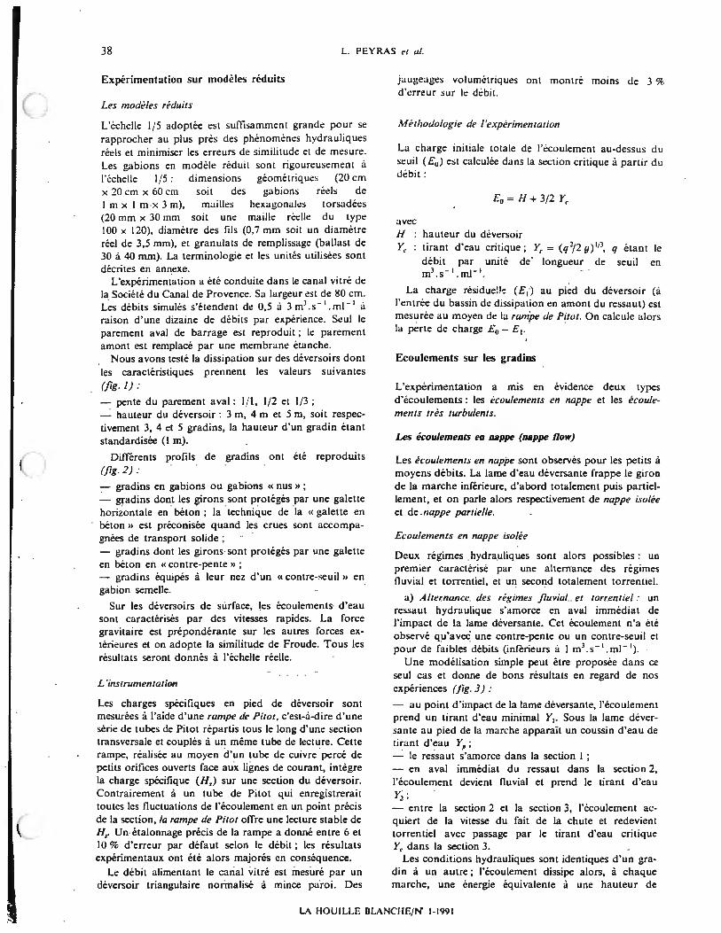
Nous avons teste la dissipation sur des deversoirs dont !es caracteristiques prennent !es valeurs suivantes (fig . 1):
- penle du parement aval: 1/ 1, 1/ 2 et 1/3; - hauteur du deversoir: 3 m, 4 m et 5 m, soil respec-tivement 3, 4 et 5 gradins, la hauteur d'un gradin etant standardisee (I rn).
Differents profils de gradins ont ete reproduits (fig. 2) :
- gradins en gabions ou gabions « nus » ; - gradins dont !es girons sont proteges par une galette horizontale en beton; la technique de la « galette en beton » est preconisee quand les crues sont accompagnees de transport solide ; - gradins dont les girons sont proteges par une galette en beton en « contre-pente » ;
- gradins equipes a leur nez d'un « contre-seuil » en gabion semelle. ·
Sur !es deversoirs de surface, !es ecoulements d'eau sont caracterises par des vitesses rapides. La force gravitaire est preponderante sur les autres forces exterieures et on adopte la similitude de Froude. Tous Jes resultats seront donnes a l'echelle reelle.
L 'instrumentation
Les charges specifiques en pied de deversoir sont mesurees a !'aide d'une rampe de Piror. c'est-a-dire d'une serie de tubes de Pitot repartis tous le long d'une section transversale et couples a un meme tube de lecture. Celle rampe, realisee au rnoyen d'un tube de cuivre pc!rce de petits orifices ouverts face aux lignes de courant, integre la charge specifique (H,) sur une section du deversoir. Contrairernenl a un tube de Pilot qui enregistrerait toutes !es fluctuations de l'ecoulemenl en un point precis de la section, la rampe de Piror off re une lecture stable de H,. Un etalonnage precis de la rarnpe a donne entre 6 et 10 % d'erreur par defaut selon le debit ; !es resultats experimentaux ont ele alors majores en consequence.
Le debit alimentant le canal vitre est mesure par un deversoir triangulaire normalise a mince paroi. Des
jaugeages volumetriques onl montre moins de 3 % d'crreur sur le debit.
Me1hodo/ogie de /'experimentation
La charge initiale totale de l'ecoulemenl au-dessus du seuil (£0 ) est calculee dans la section critique a partir du debit:
£ 0 =fl+ 3/2 Y,
avec fl hauteur du deversoir Y, : tirant d'eau critique; Y. = (q 2/2 g) 113, q etant le
debit par unite de · longueur de seuil en rn3 . s- 1 . m1- 1
•
La charge residue!!'! (£1) au pied du deversoir (a l'entree du bassin de dissipation en amont du ressaut) est mesuree au moyen de la rumpe de Piwr. On calcule alors la perle de charge £ 0 - £ 1•
Ecoulements sur les gradins
L'experimentation a mis en evidence deux types d'ecoulements : !es ecoulemenrs en nappe et !es ecoulemenrs rres rurbu/ents.
Les ecoulemeats ea aappe (nappe flow)
Les ecuulements en nappe sont observes pour !es petits a moyens debits. La lame d'eau deversante frappe le giron de la marche inferieure, d'abord totalement puis partiellernent, et on parle alors respectivernent de nappe isolee et de nappe parriel/e.
Ecoulements en nuppe isolee
Deux regimes hydrauliques sont alors possibles : un premier caracterise par une altemance des regimes t1uvial et torrentiel, el un second totalement torrentiel.
a) Alrernance des regimes fluviul el rorrenriel : un ressaut hydraulique s'amorce en aval immediat de l'impact de la lame deversante. Cet ecoulement n'a i:te observe qu'avec· une contre-pente ou un contre-seuil et pour de faibles debits (inferieurs a I m3 .s - 1 . rn1- 1
) .
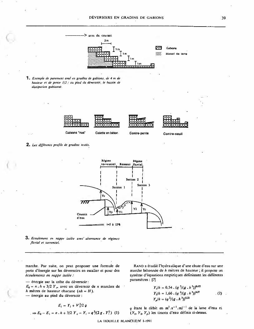
Une modelisation simple peut etre proposee dans ce seul cas et donne de bons resultats en regard de nos experiences (jig. 3) :
- au point d'impact de la lame deversanle, l'ecoulement prend un tirant d'eau minimal Y1• Sous la lame deversante au pied de la marche apparait un coussin d'eau de Lirant d'eau YP ; - le ressaul s'amorce dans la section I ; - en aval immediat du ressaut dans la section 2, l'ecoulement devient lluvial et prend le tirant d'eau Y2; - entre la section 2 et la section 3, l'ecoulement acquiert de la vitesse du fait de la chute et redevient torrentiel avec passage par le lirant d'eau critique Y, dans la section 3.
Les conditions hydrauliques sont identiques d'un gradin a un autre; l'ecoulernent dissipe alors, a chaque marche, une energie equivalente a une hauteur de
LA HOUILLE BLANCI-IE/N" 1-1991
DEVERSOIRS EN GRADINS DE GABIONS
--------> sens du courant
2m i----;
r,m r,m
~~~""". '". I,m
1. Exemple de parenumt aval en grudins de gabions. de 4 m de l,au1eur et de pente I /2; au pied du deversoir. le bassin de dissipation gabionne.
Gabions ·nus· Galena en belOn
2. us differents profits de gradins 1estes.
1m
Contre-pente
Regime Regime torrentiel Ressaut fluvial
I I I I
Coussin d'eau
Section
i=S i 15'1>
3. Ecoulemenl en nappe isolee avec ahernance de regimes jluvial el rorrentiel.
I I l l
Section 2 I I
Y2
Section 3 I I I I
Contre-seuil
39
marche. Par suite, on peut proposer une formule de perte d'energie sur les deversoirs en escalier et pour des ecoulements en nappe iso/ee :
- energie sur la crete du deversoir:
RAND a etudie l'hydraulique d'une chute d'eau sur une marche betonnee de h metres de hauteur ; ii propose un systeme d'equations empiriques definissant les differents parametres : (7)
£ 0 = n. h + 3/2 Y <' avec un deversoir de n marches de h metres de hauteur chacune (nh = H). - energie a u pied du deversoir :
Ei = Yi + V ~/2 g
= E0 - Ei = n.h +3/2 Y, - Yi - q 2/(2g. Y~) (I)
Yi/h = 0,54 . (q 2/ (g • h 3))°'•2s
Y,Jh = 1,66. (q 2/ (g . h 3))°·27
Yp/h = (q 2/(g . h 3))°-22
(2)
q etant le debit en m3 • s - i . ml - i de la lame d'eau el ( Yi, Y2, Yp) les tirants d'eau definis ci-dessus.
LA I IOU II.I.E BLANC II E/ N' 1- 1991
40 L. PEYRAS et al.
Ecou/emem en nappc isolee sur un deversoir de penle 1/3 el de 4 m de haureur ; gradins equipes d 'une cun1re-pen1e ; u/ternunce des regimes fluviu/ el iorrenlie/ ; di:bi1 0,60 m1.s - 1.mJ - 1
•
Ecou/emenl en nappc isolee sur un deversoir de penle I/I el de 5 m de hmaeur ; gradins pro1eges par une gale/le en beion ; regime 1orren1ie/; deb~/ 1,03 m1.s- 1.m1- 1
•
LA HOUII.LF. BLANCHE,'N' 1-1991
• I
DEVERSOIRS EN GRADINS DE GABIONS
Ecouiement tres turbulent sur un deversoir de pente J / 1 et de 5 m de hauteur ; gradins en gabions « nus » ; regime torrentieJ ; debit 2,17 m 3.s- 1.m1- 1
•
Ecoulement tres turbulent sur un deversoir de pente 1/1 et de 5 m de hauteur; gradins en gabions "nus» ; regime torrentieJ: debit 2,45 m 3.s- 1.m1- 1
•
LA HOUILLE llLANClff/N' 1-1991
41
42 L. PEYRAS et al.
4. Ecvul<·ment en nappe isolee avec regime constammenl wrn,ntiel.
Turbulence
5. Ecoulement en nappe partielle.
Phase de mise en vitesse; ~coulement turbulence
Enuainement de l'air; zone fortemcnt bouillonnantc
7. Debit un11aire /imite q (m 3/s/ml) entre /es ecou/ements en nappe et /es ecoulements tres turbulents, en fonction de la pente i (m/m) pour des deversoirs m grndins de gabions K nus».
La combinaison Jes i:4uations (lJ ct (2) pcrmel de calculer la pcne de charge sur les di:versoirs en escalier et on peut verilic::r la validiti: de ces formules pour des structures en gradins de gabions en prenant h = I m . Les resultats de nos experiences, concernant les ecoulemenrs en nuppe isoli:e mais aussi !'ensemble des ecoulements en nuppe , sont proches des ri:sultats obtenus avec la modelisation: la dissipation reelle est au maximum 10 % superieure a la dissipation calculi:e a partir de la modelisation. Cette difference entre !'experimentation et la modelisation s'explique car cenains parametres comme les infiltrations dans les gabions, les differences de rugosite entre le gabion et le beton ou encore la pente du deversoir, ne sont pas consideres dans la modelisation.
b) Regime rorrenriel : En absence de contre-seuil ou de contre-pente, la vitesse de l'eau· _reste forte et le ressa ut hydraulique est chasse en aval de la marche. On observe un fort bouillonnement en aval de la zone d'impact de la lame deversanle, mais l'ecoulement reste torrentiel tout le long du deversoir (fig. 4 ) .
Les ecoulements en nuppe sl.lr les ·gradins horizontaux (profils « gabions nus» et « galette en beton ») sonl systematiquement en regime torrentiel. Sur Jes deversoirs equipes d'une contre-pente ou d'un contre-seuil, le regime devient torrentiel a partir d'un certain debit.
Ecoulements en nappe partiel/e
La lame deversante frappe pour partie le giron de la marche inlerieure et l'eclatement des jets a chaque gradin provoque un fort bouillonnement. Le regime reste torrentiel tout le Jong ~es gradins (fig. 5) .
Dissipation des ecoulements en nappe
La dissipation de l'energie des ecoulements en nappe se realise en deux phases : lors du choc de la lame sur la marche, puis essentiellement dans la zone de bouillonnement qui suit l'eclatement du jet, avec ou sans formation d'un ressaut.
On peul evaluer dan·s une premiere approche la dissipation de l'cnergie sur ies dcversoirs en gradins de gabions en extrapolanl la modelisation des ecoulenumts en nuppe iso/ee a !'ensemble des ecoulements en nappe. Nos resultats ont montrc que cette extrapolation a partir des formules (I) et (2) est valide a 10 % pres.
Les ecoulements tres turbu/ents (skimming flow)
!ls sont observes pour les moyens a forts debits ; on ne peut plus distinguer alors de lame d'eau et le deversoir est totalement immergc dans un courant fort et relativement lisse.
D'amont en aval, on peut distinguer deux zones (fig.6):
- une premiere zone transitoire sur Jes deux premiers gradins: l'ecoulement s'accelere jusqu'a atteindre une vitesse limite maximale V mu ou !es phenomenes d'entrafoement de !'air apparaissent ; l'ecoulement ne prcsente pas de bouillonnement dans cette phase de mise en vitesse et la surface fibre du courant forme une ondulation lisse au-dessus du deversoir ; - l'ecoulement a atteint la vitesse V mu d'apparition de l'entrainement de l'air. Les particules d'air se melent
LA HOUILI.E ALANCIIE/ N' 1-1991
DEVERSOIRS EN GRADINS DE GABIONS 43
alors au courant d'eau et un bouillonnement intense se prolonge en s'ampliliant jusqu'au pied du deversoir. Le coussin d'eau au pied des gradins a laisse place a un rouleau de fo nd dans lequel on aperc;oit la rotation de bulles d 'ai r entrainees ; le courant se deplace le long du deversoir, s'appuyant sur le rouleau de fond d'une part et sur le nez des marches d'autre part .
La vitesse d'apparition de l'entrainement de l'air ne depend que des caracteristiques du deversoir, en particulier de la hauteur des marches (ici h = I m) et de la longueur des girons. Quel que soit le debit de la crue simulee Uusqu 'a 3 m3.s- 1 .ml-\ nous avons mesure V
111 .. de l'ordre de 5,5 a 6 m/s selon la pente du deversoir.
Une fois V max atteint, on note une legere diminution de la vitesse de l'eau ; outre une perte de h metres d'energie potentielle par gradin, l'ecoulement dissipe aussi une partie de son energie cinetique.
R~JARATNAM pr.opose une modelisation des ecuulement~· tres turbulents sur la base d'expcrimcntations menecs par SORENSEN [6], [8]
Limites entre ecoulements en nappe et ecoulements tres turbulents
Les ecoulements tres turbulents apparaissent pour des debits plus eleves que les ecoulements en nappe. Bien entendu, les caracteristiques geometriques des gradins interviennent dans !'initialisation de l'entrainement de !'air : une pente forte et des gradins horizontaux favorisent les ecoulements rres rurbulenrs. La figure 7 presente les limites entre !es deux regimes d'ecoulements.
Dissipation de l'energie sur lcs deversoirs en gradins de gabions
Presentation adimensionnel/e des resultats
Les parametres regissant les ecoulements sur les gradins de gabions sont :
- la pente i et la hauteur H du deversoir, qui delinissent totalement la geometrie du parement aval (II metres equivalent a H gradins); - le prolil du gradin, avec la presence ou non de contreseuil ou de contre-pente; dans un premier temps, nous nous limiterons aux gradins de gabions «nus» avec des ,girons horizontaux. - le debit par unite de longueur, qui regit, avec la pente i, le type d'ecoulement (en nappe ou tres rurbulent). - la force gravitaire preponderante sur toutes Jes forces exterieures.
Quatre parametres sont done neci:ssaires, dans le cas des gradins de gabions « nus », pour exprimer completement la variable adimensionnelle (£0 - £ 1)/H (perte de charge par unite de hauteur du deversoir):
(H0 - £ 1)/H = f(q, H, i, g)
On peut determiner classiquement deux para.metres adimensionnels decrivant (£0 - £ 1)/H :
- le premier tout logiquement choisi est la pente de l'escalier : i
- le second fait intervenir q, H et g de fac;on comparable au carre du nombre de Froude :
Ai nsi, on peut ecrire :
De la meme fac;on, la variable adimensionnelle Y1/H (tirant d'eau au pied du deversoir sur la hauteur du meme deversoir) s'exprime : .
A partir des resultats experimentaux, nous avons trace des abaques (jig. 8 er 9, page su\v.) donnant en ordonnee Y 1 = (£0 - £ 1 )/H et Y2 = Y1/H en fonction de l'abscisse X = q 2/( g . H 3) et du parametre i de la fac;on suivante :
- compte tenu que Y 1 et Y2 tendent respectivement vers I et O lorsque X tend vers zero, Jes courbes retenues sont de la forme
- on ajuste ces courbes .aux nuages de points par la methode des moindres carres apres transformation logari thmiq ue.
Les coeOicients ajustes sont donnes sur Jes rabies I er I/ (page suiv.).
Domaine de Yalidite des abaques
On se limite aux debits inferieurs a 3 m3. s- I. m1- 1
• Audela, des risques d'endommagements du deversoir sont a era ind re (cf. section « deformations des gabions » ).
Les abaqu.:s (jig. 8 et 9) prennent en compte les experiences conduites sur des deversoirs de 3, 4 et 5 m de hauteur. La representation adimensionnelle permet d'extrapoler ces resultats. Nous preconisons neanmoins de se limiter a des hauteurs comprises entre 2 et 7 m car, pour des hauteurs plus importantes, on s'eloignerait par trop du domaine de nos experiences.
Bien entendu, on peut interpoler les resultats pour les deversoirs de pentes intermediaires, comme par exemple 1/ 1,5 OU 1/2,5.
Methodologie de dimensionnement du bassin de dissipation
Connaissant la geometrie du deversoir (pente, hauteur et longueur deversante) et la crue de projet, nos travaux permettent de determiner le tirant d'eau Y1 correspondant a des gradins de gabions «nus» (abaque fig . 9).
Pour dimensionner le bassin de dissipation, on calcule alors (jig . 10) :
- le nombre de Froude F 1 au pied du deversoir:
LA HOUILLE BLANCHE/N' 1-1991
44 L. PEYRAS el al.
(EO·E1 )/H
0 ,9
-- =~~ ==ll~ l:;,:£1~J-A I I i I -- - 1-,- I . - ~ . I
o - - - - • - - ~~ - r I l i
I -'b- .- ., .>t- ! D '~,.., • . ' Ill'. , u -'-"' r •!r I I ~ -'4 r ~ .,_ p I
I I ' f ' ' -A ' p ' ' -::;;,; ' '
I I L IC I ' o ...._~' ' . .i. ' ,p \ ''I'.
I - '.J u •, \
' 'I \
' \
0,8
0,7
0,6
0,5
0,4 \ 0
0 , 3
0,2
0, 1
0
0,0001
I
0,001
D Pente 1/1 A Pente 1/3
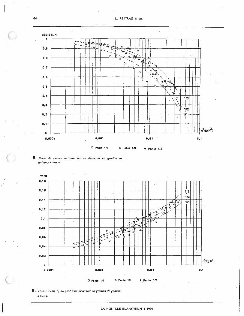
8. Perle de charge unilaire sur un dhersoir en gradins de gabion.s « nus ».
Y1/H
0, 18
0, 16
0 , 14
0 , 12
0 , 1 .
0,08
0 ,06
0 ,04
0,02
0
0,0001
, - ::::::: :.c ... - - --... -
.... -
~
- 'LI D ,. : -1 -:d .. -tr - --
~--::~ u -
0
0,001
--~ I ,. ' -· .. ::. -· Q ....
C
D Pente 1/1 A Pante 1/3
9. Tirant d 'eau Y1 au pied d'un deversoir en gradins de gabions
« IIUS» .
A ~ -)-
0,01
• Pente 1/2
I /
// l
..... J...- f . .:-9 ~ JP"".,.,
'
t:i:: f"o H ~ Ir
p[
I
I
0,01
• Pente 1/2
LA HOUILLE RLANCHE/ N" 1-1991
' \ \ \
\· \
/ /
/
L+ •o' ..... _.. ( /
,.6 /
p- "
I I
I
1/3
I I
1/2 I
1/1
0, 1
I 1/3
I
1/2
1/1
0, 1
Pente 1/3 (16
Pente 1/2 (25 Pente 1/1 (28
Pente 1/3 (15 Pente 1/2 (24 Pente 1/1 (28
DEVERSOI RS EN GRADINS DE GAUIONS
Table I Relation entre Y, = (E0 - E1 )IH et X = q2!(g. H3
) sous la forme 1/(1 - Y,) = a,. K'; coefficients a, et b 1 ajustes ; coefficient de determination r2.
- le tirant d 'eau conj ugue Y2 en fin de ressaut :
, :? I/ :? Y2 = 0,5. y I . [( I + 8. F 1) - I]
la longueur L du bassin de dissipation par la forrnule empirique (11] : L = 6 Y2
- la profondeur D du bassin de dissipation permettant d'atteindre le tirant d'eau normal Y" de la riviere; Y" ne depend que des conditions aval :
Le type de gradin modifie la dissipation de l'energie :
- les galettes en beton coulees sur le giron des marches etanchent partiellement le deversoir et la dissipation est moindre ; pour dimensionner alors exactement la fosse de dissipation, l'e!'-perience montre que h• longueur L, calculee par la methode ci-dessus decrite correspondant aux gradins en gabions « nus», doit etre majoree respectivement de 15 %, 8 % et O % pour les pentes 1/3, 1/2 et 1/ 1. - Jes contre-pentes et les contre-seuils creent des poches d'eau qui amortissent !es lames deversantes et induisent la formation de ressauts hydrauliques; la dissipation de l'energie est done amelioree. Selon la pente du deversoir, le bassin de dissipation est susceptible d'etre raccourci jusqu'a 10 % (5).
Discussion
La perte de charge par unite de hauteur (£0 - £ 1)/H decroit fortement lorsque q 2/(g. H 3
) croit et done, a hauteur H constante, lorsque le debit augmente. Ce phenomene s'explique par le changement de regime (passage de l'ecoulement en nappe a l'ecoulemenr rres turbulent) qui se produit quand q 2/(g • H 3
) augmente. La dissipation de l'energie des ecoulements rres rurbulenrs est nettement inferieure a celle qui se realise !ors des ecoulemenrs en nappe.
On note egalement que Jes courbes des variables (£0 - £ 1)/H et Y1/H correspondant aux dilTerentes pentes ont tendance respectivement a se confondre lorsque q 2/ (g. H 3
), et done q, diminue. En elTet comme ii est decrit dans la modelisation des ecou/emenrs en nappe iso/ee, on retrouve alors Jes memes conditions hydrauliques d'un gradin a un autre, et ce independamment de la pente du deversoir.
Deformations des gabions
Les experiences sur modeles reduits ont mis en evidence certaines deformations des gabions constituant le deversoir. Ces derniers sont sensibles au deplacement de leurs materiaux de remplissage. II est primordial d'apporter un soin particulier a leur realisation, ainsi qu'il est decrit dans [2]:
- qualite et agencement des pierres a la partie superieure de ces gabions ; - strict respect des regles de granulometrie (dimension des materiaux superieure a 1,5 fois la maille).
Si !es gabions sont exposes a ae- ·- tortes crues (superieures a 1,5 m 3 • s- 1
• ml-'), on renforce alors les grillage~ et les ligatures . On conseille egalement de rigidilier la cage metallique des 8abions en disposant une troisic:me rangee de - tirants supplementaires et en augmentant le nombre de diaphragmes dans !es gabions.
Les gabions sont sensibles au transport de materiaux solides, qui risquent de provoquer !'abrasion voire meme la rupture du grillage. Le cas echeant, on protege le giron des gradins en coulant une galette en beton de 5 a 10cm.
On peut donner une contre-pente aux gabions, tout simplement en inclinant vers l'amont !'ensemble du deversoir (fig. 11) . Les girons des marches peuvent dans ce cas egalement etre proteges par une galette en beton.
Outre une excellente dissipation de l'energie, cette structure augmente la stabilite de J'ouvrage. Elle requiert neanmoins une plus grande technicite pour la mise en ceuvre des gabions inclines.
Conclusion
Si toutefois !es regles demise en ceuvre des gabions sont respectees, !es deversoirs a parement aval en gradins de gabions peuvent supporter sans prejudice notable des crues jusqu'a 3 m3 .s- 1.rn1- 1
• C'est indubitablement la seule structure deversante gabionnee capable de supporter de telles crues ; en revanche, Jes parements aval en pentes inclinees gabionnes n'admetterit pas des debits superieurs a I m 3
. s - I . rn1- I [2], [5]. D'autre part, les deversoirs en gradins ofTrent une pre
dissipation de l'energie importante avant le bassin de dissipation. Cette elude permet de quantifier precise· ment cette dissipation sur les gradins et !es parametres qui definissent le bassin .
Les resultats finaux conduisent a une economie de 10 a 30 % sur la longueur du bassin de dissipation par rapport aux longueurs obtenues avec !es methodologies jusqu'a present utilisees. Connaissant le cout de l'evacuateur de crue sur ce type de barrage, l'interet economique se situe entre 5 et 10 % sur !'ensemble du projet.
Remerciements
Nous tenons a remercier la Societe du Canal de Provence pour la qualite des moyens de travail qui nous a ete offerte pendant !'experimentation.
LA l!OUILLF. RLANC'HE/N' 1-1991
DEVERSOIRS EN GRADINS DE GABIONS 4 7
ANNEXES
I. Unites
ml metre lineaire m1 . s- 1
• ml- 1debit par unite de longueur de seuil m/ m pente du deversoir
2. Notations
Y, Tirant d'eau critique Y 1 Tirant'd'eau \IU pied du deversoir Y, Tirant d'eau conjugue ,i Y1 en aval du ressaut
YP Tirant d'eau du coussin d'eau sous la lame deversanle
£ 0 Charge tolale de l'ecoulement sur le seuil du dcversoir
£ 1 Charge totale de l'ecoulement au pied du deversoir q Debit par unite de longueur de seuil g Accelenttion de la gravite H Hauteur du deversoir h Hauteur d'un gradin n Nombre de gradins du deversoir
Pente du deversoir V", \ ,esse de l'ecoulement dans la section m H, Charge specifiq ue : H, = y + V 2/2 g
3. Terminologie relative aux gradins
Nez
-----> sens du courant Cote OU hauteur
Pied
Giron
Bibliographie
[I] AGOSTINI (R.), BIZZARI (A.), MASETTI (M.) : Ouvruges j]exibles pour lronrons torrentiels et j]uviuux ( /" partie : Ou1·rages transl·ersaux) . Ed. France Gabions s.a., Le Pouzin, 1987.
[2] CEMAGREF: Les ouvrages en gabions. En cours d'edition par le Ministere Frarn;:ais de Ia Cooperation el du Developpemenl ( Edition precedt:nte : Cullectiun Techniques Rura/es en Afrique, Ed. Eyrulles, Paris. J',174) .
[3] DURAND (J.-M .): Etude de variantes techniques dans la conception des petits barrages en terre au Burkina Faso. Ed. CEMAGREF groupement d 'Aix-en-Provence, Le Tholonet. mai 1989.
[4] ESSERY (S.), HORNER (W.): The hydraulic design of stepped spillways (CIR/A Report 33). Ed. CIRIA (Construction Industry Research and Information Association), Landres, janvier 1978.
[5] PEYRAS (L.): Etude de la dissipation de /'energie sur /es deversoirs en gradins de gabions. Ed. CEMAGREF groupement d'Aix- en-Provence, Le Tholonnet, mai 1990.
[6] RAJARATNAM (N.) : Skimming flow in stepped spillways. J . hydrau/. eng., ASCE. vol.116, n·4, avril 1990, pp.587-591.
[7] RAND (W.) : Flow geometry at straight drop spillways. Proc. ASCE, 81 E, Paper 79 1, septembre 1955, pp. 1- 13.
(8] SORENSEN (R. M .) : Stepped spillway hydraulic mode investigation. J. /iydraul. e11g .. ASCE. vol. 111 , n· 1~. decembn: 1985, pp. 1461- 1472.
[9] STEPHENSON (D.) : Gabion energy dissipators. Treizieme congres des grands barrages, New-Delhi, 1979. Ed. Commission Internationale des Grands Barrages, Q . 50, R. 3. pp. 33-43, 1979.
(10] STEPHENSON (D.) : Rockfl/1 in hydraulic engineering. Ed. Elsevier scientific publishing company, Collection Developments in geotechnical engineering, vol. 27, Amsterdam, Oxford, New York, 1979.
(11] UNITED STATES DEPARTMENT OF THE INTERiOR (Bureau of Reclamation). Design of small dams. Ed. Water R~sourcc:; Technical Publication (United Stales Government Printing Office), Denver, 1987.