UNITED STATES GOVERNMENT MEMORANDUM To: Public Information May 28, 2020 From: Subject: Control # Type Plan Coordinator, OLP, Plans Section (GM 235D) Public Information copy of plan - Control S-07979 - Supplemental Development Operations Coordination Document Lease(s) - OCS-G06898 Block - 989 Viosca Knoll Area OCS-G09771 Block - 28 Mississippi Canyon Area Operator - Talos Petroleum LLC Description - Rig Type - Well SS005 Drillship or DP Semisubmersible Attached is a copy of the subject plan. It has been deemed submitted and is under review for approval. Ronald O'Connor Plan Coordinator
Transcript
UNITED STATES GOVERNMENT MEMORANDUM
To: Public Information
May 28, 2020
From:
Subject:
Control #
Type
Plan Coordinator, OLP, Plans Section (GM 235D)
Public Information copy of plan
- Control S-07979
- Supplemental Development Operations Coordination Document
It has been deemed submitted and is under review for approval.
Ronald O'Connor Plan Coordinator
September 25, 2019
Bureau of Ocean Energy ManagementNew Orleans Regional OfficeATTN: Plans Section1201 Elmwood Park BoulevardNew Orleans, LA 70123
To Whom It May Concern:
Talos Petroleum LLC has reviewed NTLs 2008-G04, 2015-N01 and other relevant NTLs and FAQs for the activities proposed herein and included in this submittal all pertinent proprietary and public information and documentation in regards to those activities.
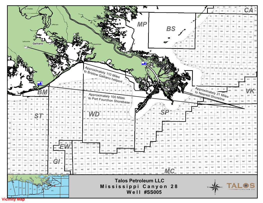
The activities proposed in his plan include drilling, completion and production of Subsea Well No. 005, Mississippi Canyon Block 28, Lease OCS-G 09771, and the installation of one lease term pipeline.
The proposed operations are expected to commence on or about February 1, 2020.
All questions and/or correspondence regarding this plan should be submitted to Erin Harold at 713-335-6952 or via email at [email protected].
APPENDIX E MINERAL RESOURCE CONSERVATION INFORMATION
APPENDIX F BIOLOGICAL, PHYSICAL, & SOCIOECONOMIC INFORMATION
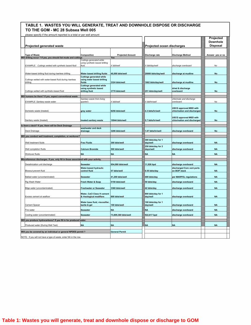
APPENDIX G WASTES AND DISCHARGES INFORMATION
APPENDIX H AIR EMISSIONS INFORMATION
APPENDIX I OIL SPILLS INFORMATION
APPENDIX J ENVIRONMENTAL MONITORING INFORMATION
APPENDIX K LEASE STIPULATIONS INFORMATION
APPENDIX L ENVIRONMENTAL MITIGATION MEASURES INFORMATION
APPENDIX M RELATED FACILITIES & OPERATIONS INFORMATION
APPENDIX N SUPPORT VESSELS AND AIRCRAFT INFORMATION
APPENDIX O ONSHORE SUPPORT FACILITIES INFORMATION
APPENDIX P COASTAL ZONE MANAGEMENT (CZMA) INFORMATION
APPENDIX Q ENVIRONMETAL IMPACT ANALYSIS
APPENDIX R ADMINISTRATIVE INFORMATION
APPENDIX APLAN CONTENTS
PLAN INFORMATIONA)
Included in the attachments for this appendix is the OCS Plan Information Form-137, providing information on the activities proposed herein.
Previous activity approved on this lease included an approval for the drilling, completion and production of MC28, Well No. SS004 (formerly Well No. A034). Please be advised this activity was completed as proposed. The well is now in TA status.
This DOCD includes proposed drilling, completion and production of subsea well location no. 005, and the installation of one lease term pipeline.
LOCATIONB)
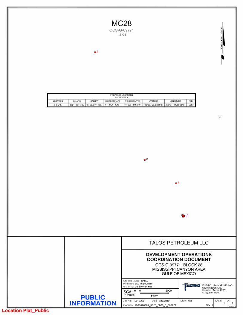
A map depicting the proposed surface and bottomhole locations of the proposed well locations is included as an attachment to this appendix as Proprietary Information.
A map depicting the proposed surface locations of the proposed well locations is included as an attachment to this appendix as Public Information.
SAFETY AND POLLUTION PREVENTION FEATURESC)
Talos Petroleum LLC (Talos) proposes to utilize a DP Semisubmersible or Drillship to drill the well. Talos is requesting permission to have the option of choosing the most appropriate and available drilling unit at the time the Application for Permit to Drill (APD) is filed. A description of the drilling unit is included on the OCS Plan Information Form. Rig specifications will be made part of each Application for Permit to drill.
Safety features on the drilling unit will include well control, pollution prevention, and blowout prevention equipment as described in Title 30 CFR 250, Subparts C, D, E, and G; and as further clarified by the DOI Notices to Lessees, and current policy making invoked by the DOI, Environmental Protection Agency, and the U.S. Coast Guard. A Safety & Environmental Management System consistent with Title 30 CFR 250 Subparts “O” & “S” will be in effect during the proposed operations. In addition, the Well Control System consisting of surface BOP equipment, BOP control system, choke and kill lines, choke manifold, mud-gas separator, circulation system and monitoring (PVT) equipment will be installed and available on demand when the BOP is attached to the well. The emergency systems consisting of secondary BOP activation equipment, firefighting and abandonment equipment utilized will meet or exceed the regulatory requirements of the DOI and USCG.
Pollution prevention measures include installation of curbs, gutters, drip pans, and drains on drilling deck areas to collect all containments and debris.
The drilling rig and each of the marine vessels servicing the rig and its operations will be equipped with all USCG required navigational safety aids to alert ships of its presence in all weather conditions.
STORAGE TANKS AND/OR PRODUCTION VESSELSD)
The table below provides information on oil storage tanks with a capacity of 25 barrels or more that will be used to conduct the activities proposed herein. Since the capacities for both rig types are almost identical, this table is representative of either type rig.
Fluid Gravity(API)
TotalCapacity(bbls)
Number ofTanks
TankCapacity(bbls)
Type ofFacility
Type of Storage Tank
33°3000065000MODUFuel Oil
POLLUTION PREVENTIONE)
In accordance with NTL 2008-G04, this information is not applicable to the activities proposed herein as the State of Florida is not an affected State.
ADDITIONAL MEASURESF)
Talos Petroleum (Talos) will comply with regulations in 30 CFR Part 250 in regards to safety, pollution prevention, and early spill detection measures. Talos has also reviewed the numerous industry and
commission reports, as well as DOI's NTL's, and other guidance documents prepared since the 2010 Macondo blowout. As a result, Talos Petroleum has joined the HWCG LLC, and is also a member of Clean Gulf Associates and the National Response Corporation.
SERVICE FEEG)
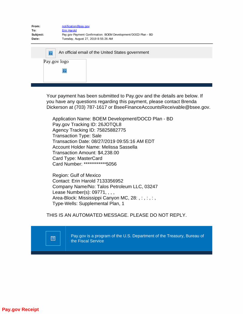
In accordance with 30 CFR 250.125, included in the attachments for this appendix is a copy of the pay.gov receipt for the required service fee for the activities proposed herein.
U.S. Department of the Interior OMB Control Number: 1010-0151
Bureau of Ocean Energy Management OMB Approval Expires: 12/31/14
OCS PLAN INFORMATION FORM General Information
Type of OCS Plan: Exploration Plan (EP) Development Operations Coordination Document (DOCD)
Company Name: BOEM Operator Number:
Address: Contact Person:
Phone Number:
E-Mail Address:
If a service fee is required under 30 CFR 550.125(a), provide the Amount paid Receipt No.
Project and Worst Case Discharge (WCD) Information
Lease(s): Area: Block(s): Project Name (If Applicable):
Objective(s) Oil Gas Sulphur Salt Onshore Support Base(s):
Platform/Well Name: Total Volume of WCD: API Gravity:
Distance to Closest Land (Miles): Volume from uncontrolled blowout:
Have you previously provided information to verify the calculations and assumptions for your WCD? Yes No
If so, provide the Control Number of the EP or DOCD with which this information was provided
Do you propose to use new or unusual technology to conduct your activities? Yes No
Do you propose to use a vessel with anchors to install or modify a structure? Yes No
Do you propose any facility that will serve as a host facility for deepwater subsea development? Yes No
Description of Proposed Activities and Tentative Schedule (Mark all that apply) Proposed Activity Start Date End Date No. of Days
Exploration drilling
Development drilling
Well completion
Well test flaring (for more than 48 hours)
Installation or modification of structure
Installation of production facilities
Installation of subsea wellheads and/or manifolds
Installation of lease term pipelines
Commence production
Other (Specify and attach description)
Description of Drilling Rig Description of Structure Jackup Drillship Caisson Tension leg platform Gorilla Jackup Platform rig Fixed platform Compliant tower
Semisubmersible Submersible Spar Guyed tower
DP Semisubmersible Other (Attach Description)
Drilling Rig Name (If Known):
Floating production system
Other (Attach Description)
Description of Lease Term Pipelines From (Facility/Area/Block) To (Facility/Area/Block) Diameter (Inches) Length (Feet)
Form BOEM- 0137 (December 2011- Supersedes all previous editions of this form which may not be used.) Page 1 of 4
Form BOEM-137
OCS PLAN INFORMATION FORM (CONTINUED) Include one copy of this page for each proposed well/structure
Proposed Well/Structure Location
Well or Structure Name/Number (If renaming well or structure, reference previous name):
Previously reviewed under an approved EP or DOCD?
Yes No
Is this an existing well or structure?
Yes No If this is an existing well or structure, list the Complex ID or API No.
Do you plan to use a subsea BOP or a surface BOP on a floating facility to conduct your proposed activities? Yes No
WCD info For wells, volume of uncontrolled blowout (Bbls/day):
For structures, volume of all storage and pipelines (Bbls):
API Gravity of fluid
Surface Location Bottom-Hole Location (For Wells) Completion (For multiple completions, enter separate lines)
Lease No. OCS
OCS OCS OCS
Area Name
Block No.
Blockline Departures (in feet)
N/S Departure: F____ L N/S Departure: F____ L N/S Departure: F____ L N/S Departure: F____ L N/S Departure: F____ L
E/W Departure: F____ L
E/W Departure: F____ L E/W Departure: F____ L E/W Departure: F____ L E/W Departure: F____ L
Lambert X-Y coordinates
X: X: X: X: X:
Y: Y: Y: Y: Y:
Latitude/ Longitude
Latitude Latitude Latitude Latitude Latitude
Longitude Longitude Longitude Longitude Longitude
Water Depth (Feet): MD (Feet): TVD (Feet):
Anchor Radius (if applicable) in feet:
MD (Feet): MD (Feet): MD (Feet):
TVD (Feet): TVD (Feet): TVD (Feet):
Anchor Locations for Drilling Rig or Construction Barge (If anchor radius supplied above, not necessary)
Anchor Name or No.
Area Block X Coordinate Y Coordinate Length of Anchor Chain on Seafloor
X = Y =
X = Y =
X = Y =
X = Y =
X = Y =
X = Y =
X = Y =
X = Y =
Form BOEM- 0137 (December 2011- Supersedes all previous editions of this form which may not be used.) Page 2 of 4
Form BOEM-137
Form BOEM-137
Location Plat_Public
From: [email protected]: Erin HaroldSubject: Pay.gov Payment Confirmation: BOEM Development/DOCD Plan - BDDate: Tuesday, August 27, 2019 8:55:26 AM
An official email of the United States government
Pay.gov logo
Your payment has been submitted to Pay.gov and the details are below. Ifyou have any questions regarding this payment, please contact BrendaDickerson at (703) 787-1617 or [email protected].
Listed in the table below are the applications and/or permits that are required to be filed prior to conductingthe activities proposed herein:
StatusIssuing AgencyApplication/Permit
Pending SubmittalBOEMConservation Information Document
PendingEPANPDES
Pending SubmittalBSEELease Term Pipeline Application
PendingUSCGNav-Aid Permit
Pending SubmittalBSEEDWOP
PendingUSCGRig Emergency Evacuation Plan
PendingBSEEApplication for Permit to Drill (APD)
Pending SubmittalBSEEConceptual DWOP
DRILLING FLUIDSB)
In accordance with BOEM guidance, the required drilling fluid information has been incorporated into the Waste & Discharge tables which are included in the attachment(s) to the Waste & Discharge Information appendix.
PRODUCTIONC)
PROPRIETARY INFORMATION
OIL CHARACTERISTICSD)
In accordance with NTL 2008-G04, this information is not applicable to the activities proposed herein as this is a DOCD that does not propose the production, handling, transporting or storing of oil where the State of Florida is an affected State, the activities proposed are not within the Protective Zones of the Flower Garden Banks and Stetson Bank, nor are we proposing to install a surface facility in water depths greater than 1,312 feet or a surface facility to support a subsea development in water depths greater than 1,312’.
NEW OR UNUSUAL TECHNOLOGYE)
In accordance with NTL 2008-G04, this information is not applicable to the activities proposed herein as no new or unusual technology as defined in 30 CFR 250.200 will be utilized to carry out the proposed activities. Talos will endeavor to use the best available and safest technologies (BAST), as referred to in 30 CFR 250, provided it is proven for the well conditions anticipated and is reasonably available at the time of well operations.
BONDING STATEMENTF)
The bond requirements for the activities and facilities proposed herein are satisfied by a $3,000,000 area-wide bond, furnished and maintained according to 30 CFR Part 556, Subpart I; NTL No. 2015-N04, “General Financial Assurance;” and will provide additional security under NTL No. 2016-N01, "Requiring Additional Security," upon request from the BOEM.
OIL SPILL FINANCIAL RESPONSIBILITYG)
Talos Petroleum, company number 01834, has demonstrated oil spill financial responsibility (OSFR) for the activities/facilities proposed herein. The OSFR insurance coverage is renewed annually in May and complies with 30 CFR Part 253, and NTL No. 2008-N05, "Guidelines for Oil Spill Financial Responsibility for Covered Facilities." Talos Petroleum's insurance certificate for oil spill financial responsibility is $150,000,000.
DEEPWATER WELL CONTROL STATEMENTH)
Talos Petroleum (01834) has the financial capability to drill a relief well and conduct other emergency well control operations.
SUSPENSION OF PRODUCTIONI)
In accordance with NTL 2008-G04, this information is not applicable to this Development Operations Coordination Document as no suspensions of production have been approved, or are in the process of being obtained, or anticipated to be sought to hold the subject lease(s) or unit.
BLOWOUT SCENARIOJ)
A blowout scenario and supplemental informatoin requirements, as outlined in NTL 2015 N01, is included as an
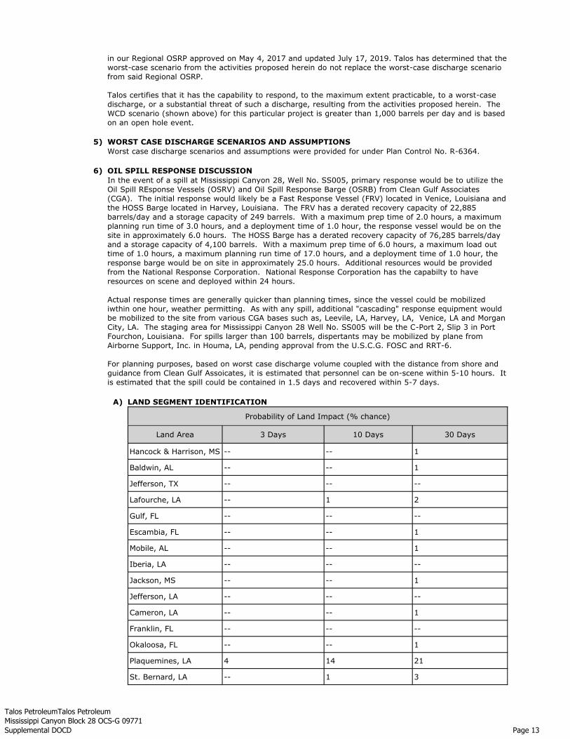
In the event of a spill at Mississippi Canyon 28 Well 004, primary response would be to utilize the Oil SpillResponse Vessels (OSRV) and Oil Spill Response Barge (OSRB) from Clean Gulf Associates (CGA). The initialresponse would likely be a Fast Response Vessel (FRV) located in Venice, Louisiana and the HOSS Bargelocated in Harvey, Louisiana. The FRV has a derated recovery capacity of 22,885 barrels/day and a storagecapacity of 249 barrels. With a maximum prep time of 2.0 hours, a maximum planning run time of 3.0 hours,and a deployment time of 1.0 hour, the response vessel would be on site in approximately 6.0 hours. TheHOSS Barge has a derated recovery capacity of 76,285 barrels/day and a storage capacity of 4,100 barrels.With a maximum prep time of 6.0 hours, a maximum load out time of 1.0 hours, a maximum planning runtime of 17.0 hours, and a deployment time of 1.0 hour, the response barge would be on site in approximately25.0 hours. Additional resources would be provided from the National Response Corporation. NationalResponse Corporation has the capability to have resources on scene and deployed within 24 hours.
Actual response times are generally quicker than planning times, since the vessel could be mobilized within onehour, weather permitting. As with any spill, additional "cascading" response equipment would be mobilized tothe site from various CGA bases such as, Leeville, LA, Harvey, LA, Venice, LA, and Morgan City, LA. Thestaging area for Mississippi Canyon 28 Well 004 will be the C-Port 2, Slip 3 in Port Fourchon, Louisiana. Forspills larger than 100 barrels, dispersants may be mobilized by plane from Airborne Support, Inc. in Houma,LA, pending approval from the U.S.C.G. FOSC and RRT-6.
For planning purposes, based on the worst case discharge volume coupled with the distance from shore andguidance from Clean Gulf Associates, it is estimated that personnel can be on-scene within 5-10 hours. It isestimated that the spill could be contained in 1.5 days and recovered within 5-7 days.
Talos Petroleum LLC focuses on an integrated approach to a loss of well control event (blowout), including prevention, intervention/containment, and recovery. We believe the best way to manage blowouts is to keep them from occurring. A significant amount of time and effort goes into the design and execution of wells and into building and maintaining a competent staff whose primary focus is the construction of safe and environmentally sound wells.Talos Petroleum LLC is a member of Helix Well Containment Group (HWCG) and has an agreement with Clean Gulf Associates and Helix Energy Solutions Group which provides access to containment equipment owned and operated by Helix Energy Solutions. The containment equipment is collectively described as “The Helix Fast Response System” which consists of “Capping Stacks” and surface equipment which may be used for processing well fluids. Talos Petroleum LLC will prepare and provide a detailed Well Containment Plan(WCP) for its intended operations that is consistent with NTL BOEM 2015-N01 and other requirements imposed by regulatory authorities. The WCP will incorporate applicable lessons learned from the Macondo response and other industry workshops.
The Worst Case Discharge (WCD) blowout scenario for this Revised DOCD is based on NTL BOEM 2015-N01and any associated guidance found in Frequently Asked Questions (FAQ) documentation. The WCD does nottake into account potential flow mitigation factors such as bridging, obstructions in the wellbore, or reservoirbarriers.
The Worst Case Discharge blowout scenario indicated here is for Talos Energy's Providence development project area WCD volume submitted and found acceptable under plan control number R-6364.The Providence development project area consists of adjacent blocks Mississippi Canyon 28 (OCS-G 09771) and Viosca Knoll 989 (OCS-G 06898).
6,056,352Total Volume of Spill (bbls) For Days
102Duration of Flow (Days) Based on Relief Well (days to secure rig, mob & drill relief well)
Expect bridging or hole collapse to occur in 7-15days
3.2Average
Current BHP is estimated to be low. Offset BHP from theA-13 well indicates a BHP of +/- 3700 psi or 7.4 ppe.
2Low Bottom Hole Pressure
Target sands have been produced and are thought tohave a current BHP of 3700 psi.
2Objective Zone has beenPreviously Produced
N/AN/AAbnormally pressuredformations below current casing
N/AN/AUnconsolidated formationsbelow current casing
Typical GOM Miocene formations are expected. Nogrossly unconsolidated formations are expected.
3Unconsolidated FormationsBelow Previous Casing
The planned hole section is 2549' of 8.5" open holelength at a 72.1 degree inclination.
2Open Hole Length
There are no known water sands between theintermediate casing point and the planned TD below thetarget interval.
5Exposed Water Sands in OpenHole
There is a water contact in the reservoir identified in theMC 72 TB8 wellbore.
3Water Contact in Reservoir
Due to high inclination angle of the wellbore (72.1*),hole stability issues are expected.
1Hole Erosion & Collapse
Shale pore pressures are expected to be in the range of12.3-12.5 ppge vs expected sand pore pressures of 7.4ppge.
3Excessive Drawdown
The previous drilling liner and tieback will have additionalwall thickness to prevent casing wear issues during thelife of the well. Therefore, the collapse rating of thestring will be increased.
The objective is thought to be an underpressure oilreservoir.
6Excessive hydrostatic pressureloss due to replacement of mudwith reservoir fluids
Upper MioceneFormation Type
Discussion for Selection of Likelihood ValueBridgingLikelihood
Assessment Criteria
BRIDGING ASSESSMENT :8.5"
The hole bridging discussion is based on the following factors:
The bridging assessment indicated above is for Talos Energy's Providence development project area WCD volume submitted and found acceptable under plan control number R-6364.
The Providence development project area consists of adjacent blocks Mississippi Canyon 28 (OCS-G 09771) and Viosca Knoll 989 (OCS-G 06898).
From the table above, Talos Petroleum LLC believes that there is a moderate to high likelihood for a bridge to form. Based on the bridging assessment criteria this blowout event should be approximately 7-
Blowout Scenario
15 day(s) if it occurs while drilling with open hole exposed below the drilling liner. The most likely cause of wellbore bridging anticipated is to be bore hole collapse. Several components will contribute to this, such as: high production rates from unconsolidated hydrocarbon sands, any water exposed from the hydrocarbon zones which will water wet and weaken the exposed shales, and/or high pressure differentials across the shales.
MEASURES TO ENHANCE THE ABILITY TO PREVENT A BLOWOUT2)
Rig equipment, at a minimum, will include the following:A diverter system which is designed, installed, maintained and tested to ensure proper diversion of gases,water, drilling fluid, and other materials away from facilities and personnel when formation fluidsinadvertently enter the marine drilling riser.
A Subsea BOP, LMRP,Riser, Control system and system components, which is designed, maintained andtested to ensure well control under all anticipated well conditions. The working pressure rating of all ramBOPs will exceed the Maximum Anticipated Wellhead Pressure (MAWP) which could be encountered.Annular BOPs will likely have lower working pressurs than MAWP, however, shoudl the annulalar BOPbecome excessive, the well control will be shifted to the ram preventors. Surface equipment workingpressures will meet or exceed the Maximum Anticipated Surface Pressure (MASP) based on typical drillingor completion load cases with are anticipated.
A drilling fluid return flow and pit volume monitoring system along with associated materials storagecapacity with available volume to allow for maintenance and replenishment of drilling fluid and drillingfluid materials. These will be maintained at the drill site as necessary to ensure well control ismaintained.
3) DISCUSSION OF LIKELIHOOD FOR WELL INTERVENTION TO STOP A BLOWOUTA subsea blowout with uncontrolled release of formation fluids could result in liquid hydrocarbon release into OCS waters. A blowout could occur at any time during the life cycle of the well; beginning with its construction (drilling) to beyond its useful life when the well has to be plugged and abandoned. If this were to occur, Talos Petroleum LLC would immediately implement its Spill Response Plan (OSRP).
It is not the intent of this document to give specific details on intervention should a blowout occur; however, general information relative to this project is provided. It is generally understood that a professional assessment would be required and the work plan can only be developed once the exact conditions are known and understood. In general, Talos Petroleum LLC would simultaneously work towards securing a rig to drill a relief well and performing subsea intervention to the extent possible on the flowing well.
As a basis for discussion in this section, it is assumed that a subsurface blowout with uncontrollablerelease of formation fluids could result in liquid hydrocarbon release into OCS waters.
SPECIFIC INTERVENTION RELATED TO FIELD OPERATIONSA)
For this specific targeted reservoir, no specific intervention has been identified at this time.
BLOWOUT WITHOUT FIRE WHILE RIG IS ON LOCATIONB)
In subsea operations, at least two conditions should be considered: 1) Blowout during riserless welloperations and 2) Blowout once the riser and BOP is installed.
During riserless drilling a blowout could occur, however, the flow would exit the well near theseafloor and should not pose significant risk of ignition. Heavy drilling mud would be used to stopthe flow, however if the kill is unsuccessful, then the rig could be moved off location while the well ismonitored with an ROV.
During normal drilling operations, once the riser and BOP are installed, a blowout situation couldoccur, however proper emergency response should result in release of the LMRP which would allowthe rig to be moved off location. Once the rig is moved to a safe location, the ROV can be deployedto assess the subsea condition of the wellhead and subsea BOPE.
Once immediate actions are taken at the well-site, Talos Petroleum LLC Incident Management Team would be activated.
In general, the rig would be positioned upwind of any surface hydrocarbons. If necessary sources ofignition would be stopped and the rig would be evacuated. A perimeter would be established to keepunauthorized vessels away from danger. Limited ingress based upon the safety plan would beestablished for fire suppression vessels and a mobile work platform and ROV.
As soon as possible, a Hazard Assessment and Operations Assessment would be conducted by thesource control team. An assessment of the cause(s) for the blowout and current conditions would
Blowout Scenario
lead to the potential methods and resource requirements to be used to safely control the well.
At this time, the following could be expected:· Existing well control equipment such as BOP’s could be activated using an ROV or SAM to
shut in the well.· A source control response, established in an approved Well Containment Plan, would be
initiated by activating a response organization capable of providing capping and containment equipment & resources.
· “Capping Stack” equipment could be installed and utilized to safely shut in the well.· If required a “Cap & Flow” response would allow partial shut-in of the well while excess
liquid hydrocarbon flow is collected for transport to shore.· As soon as reasonably practicable, the well would be killed using a top kill method.· Relief well preparation and execution plans will be developed and implemented as
necessary.
BLOWOUT WITH FIRE WHILE RIG IS ON LOCATIONC)
In subsea operations, at least two conditions should be considered: 1) Blowout during riserless welloperations and 2) Blowout once the riser and BOP is installed.
During riserless drilling a blowout could occur, however, the flow would exit the well near theseafloor and should not pose significant risk of ignition. In the event of a significant gas release thatcould ignite, the drilling unit will be moved as quickly as possible to an upwind location.
During normal drilling operations, once the riser and BOP are installed, a blowout situation couldoccur, however proper emergency response should result in release of the LMRP which would allowthe rig to be moved off location. If a blowout situation occurs and the rig remains connected to thewell, then the rig will be evacuated using the rigs emergency evacuation procedures.
Once immediate actions are taken at the well-site, Talos Petroleum LLC's Incident Management Team would be activated.
A perimeter would be established to keep unauthorized vessels away from danger. Limited ingressbased upon the safety plan would be established for fire suppression vessels and a mobile workplatform containing an ROV would be established.
As soon as possible, a Hazard Assessment and Operations Assessment would be conducted by thesource control team. An assessment of the cause(s) for the blowout and current conditions wouldlead to the potential methods and resource requirements to be used to safely control the well.Equipment would have to be mobilized to provide safe access to the well and intervention could beestablished. At this time, the following could be expected:
· Existing well control equipment such as BOP’s could be activated using an ROV or SAM toshut in the well.
· The rigs LMRP connector could be released to allow the rig to be moved off location.· Stone’s source control response, established in an approved Well Containment Plan, would
be initiated by activating a response organization capable of providing capping andcontainment equipment & resources.
· “Capping Stack” equipment could be installed and utilized to safely shut in the well.· If required a “Cap & Flow” response would allow partial shut-in of the well while excess
liquid hydrocarbon flow is collected for transport to shore.· As soon as reasonably practicable, the well would be killed using a top kill method.· Relief well preparation and execution plans will be developed and implemented as
necessary.
SOURCE IGNITION TO MINIMIZE SPILL4)
The hydrocarbons associated with this plan have been classified as oil with associated gas. However, thisis an attic target and there is potential for the hydrocarbons to be classified as gas. It may beadvantageous to ignite and sustain a fire in order to minimize the amount of liquid hydrocarbons enteringOCS waters and impacting the shoreline. Purposeful ignition of the source would have to be assessed ifthe rig is on location so that well control options and equipment damage could be fully considered.
RELIEF RIG OPTIONS5)
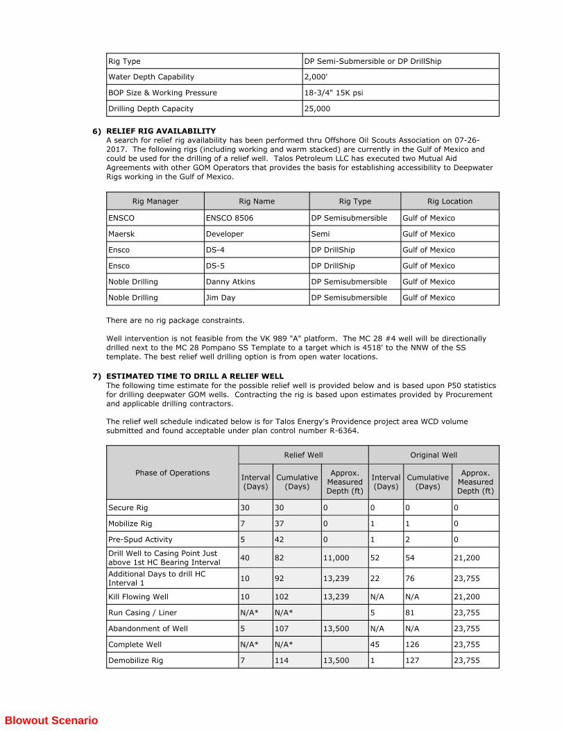
The planned well in this RDOCD and the relief well would be drilled in a similar water depth rangebetween 1,500’ and 1,850’. Drilling the relief well will require a moored, semi-submersible or DP Semi-submersible or DP DrillShip rig due to the water depth. Drilling from an offset production platform, a landlocation or utilizing a jack-up type rig is not an alternative.
Blowout Scenario
25,000Drilling Depth Capacity
18-3/4" 15K psiBOP Size & Working Pressure
2,000'Water Depth Capability
DP Semi-Submersible or DP DrillShipRig Type
6) RELIEF RIG AVAILABILITYA search for relief rig availability has been performed thru Offshore Oil Scouts Association on 07-26- 2017. The following rigs (including working and warm stacked) are currently in the Gulf of Mexico and could be used for the drilling of a relief well. Talos Petroleum LLC has executed two Mutual Aid Agreements with other GOM Operators that provides the basis for establishing accessibility to Deepwater Rigs working in the Gulf of Mexico.
Rig LocationRig TypeRig NameRig Manager
Gulf of MexicoDP SemisubmersibleENSCO 8506ENSCO
Gulf of MexicoSemiDeveloperMaersk
Gulf of MexicoDP DrillShipDS-4Ensco
Gulf of MexicoDP DrillShipDS-5Ensco
Gulf of MexicoDP SemisubmersibleDanny AtkinsNoble Drilling
Gulf of MexicoDP SemisubmersibleJim DayNoble Drilling
There are no rig package constraints.
Well intervention is not feasible from the VK 989 "A" platform. The MC 28 #4 well will be directionally drilled next to the MC 28 Pompano SS Template to a target which is 4518' to the NNW of the SS template. The best relief well drilling option is from open water locations.
ESTIMATED TIME TO DRILL A RELIEF WELL7)
The following time estimate for the possible relief well is provided below and is based upon P50 statisticsfor drilling deepwater GOM wells. Contracting the rig is based upon estimates provided by Procurementand applicable drilling contractors.
The relief well schedule indicated below is for Talos Energy's Providence project area WCD volume submitted and found acceptable under plan control number R-6364.
Approx.MeasuredDepth (ft)
Cumulative(Days)
Interval(Days)
Approx.MeasuredDepth (ft)
Cumulative(Days)
Interval(Days)
Original WellRelief Well
Phase of Operations
00003030Secure Rig
0110377Mobilize Rig
0210425Pre-Spud Activity
21,200545211,0008240Drill Well to Casing Point Justabove 1st HC Bearing Interval
23,755762213,2399210Additional Days to drill HCInterval 1
21,200N/AN/A13,23910210Kill Flowing Well
23,755815N/A*N/A*Run Casing / Liner
23,755N/AN/A13,5001075Abandonment of Well
23,75512645N/A*N/A*Complete Well
23,755127113,5001147Demobilize Rig
Blowout Scenario
Approx.MeasuredDepth (ft)
Cumulative(Days)
Interval(Days)
Approx.MeasuredDepth (ft)
Cumulative(Days)
Interval(Days)
Original WellRelief Well
Phase of Operations
127
N/A* - Not Applicable to the Relief Wells
A potential relief well location has been identified in MC 28 for the proposed location. The relief well would be directional to intercept as needed but will be dependent upon the actual well drilled and site assessment at the time of the incident. The assessment will take into account well and intervention information, met-ocean conditions and a hydrocarbon VOC assessment.
8) WELL CONTROL TRAINING & WELL CONTROL DRILLS FOR RIG SITE PERSONNELTalos Petroleum LLC (Talos) is focused on ensuring that rig site personnel are properly trained for handling well control incidents. Procedures are in place for verifying that all employees and contractor personnel who could potentially be involved in well control operations understand and can properly perform their assigned duties. Well Control training certification requirements are consistent with, and in accordance with, the IADC WellCAP* program. The IADC WellCAP program is a recommended Well Control training curriculum of BSEE.
In addition, Talos conducts audits of rig site operations to ensure that the respective rig site personnel have documentation to verify that their WellCAP certifications are current. Well control drills will be conducted regularly with each drilling crew. Each crew will be familiar with its roles and functions so that all crew members can perform their duties promptly and efficiently. The well control drill plan will outline the assignments for each crew member and will establish times to complete each portion of the drill.
The IADC WellCAP program is based on the principle that proper training, emphasizing the knowledge andpractical skills critical to successful well control, produces competent rig crews. Using quality benchmarksdeveloped together with operators, drilling contractors, professional trainers and well control specialists,WellCAP ensures that well control training schools adhere to a core curriculum developed by industry.Accreditation is achieved only after an extensive review of a provider’s curriculum, testing practices,faculty, facilities, and administrative procedures. At the Introductory Level, WellCAP provides basic wellcontrol knowledge for floorhands, derrick workers and non-technical personnel. The Fundamental andSupervisory Level WellCAP training curriculum address practical well control skills for derrick workers,assistant drillers, drillers, toolpushers, superintendents and operator drilling supervisors.
WELL DESIGN9)
CASING & CEMENT DESIGNA)
The primary objectives of an effective casing and cementing design strategy are to control formationpressures and fluids to ensure that communication between different strata and offshore watersdoes not occur. Accordingly, Stone’s casing and cementing design basis is as follows:
1) Protect freshwater aquifers from contamination 2)Support unconsolidated sediments 3)Preventthe direct or indirect releases of fluids from any stratum through the wellbore into offshore waters 4)Prevent communication between separate hydrocarbon-bearing strata 5)Casing must withstandthe reasonably anticipated stresses imposed by tensile, compressive, and buckling loads, burst and collapse pressures, thermal effects, and combinations thereof 6)The casing design must include design factors that ensure well control during drilling and safe operations during the life cycle of the well 7)The cement job design basis must ensure that cement composition, placement techniques, and waiting times result in a cement sheath placed in the annulus outside the casing with a minimum compressive strength of 500psi before drilling out of the casing or before commencing completion operations 8)The planned annular cement fill will be adequate to cover and isolate all hydrocarbon-bearing zones and isolate abnormal pressure intervals from normal pressure intervals in the well 9)As a minimum, the planned annular cement fill will be adequate to cover the annular space to 500 feet above the casing shoe and 500 feet above each zone to be isolated as defined in item 8 above 10)Casing strings must be pressure tested per 30 CFR 250.423 requirements to ensure integrity is maintained during any potential well control incidents as follows:a)Structural / Drive pipe - Not requiredb)Conductor - 200 psic)Surface & Intermediate strings back to surface or mud linei)70% of rated internal yield pressure & adjusted for differential mud hydrostatic effects if
applicable, orii)Maximum Anticipated Wellhead Pressure (MAWP) plus 500 psi if prior approval has been
Blowout Scenario
received.d)Production strings back to surface or mud linei)70% of rated internal yield pressure & adjusted for differential mud hydrostatic effects if
applicable, orii)Maximum Anticipated Wellhead Pressure (MAWP) plus 500 psi if prior approval has been
receivede)Liners (pipe strings that do not extend back to surface)i)Each drilling liner (and liner-lap) must be tested to a pressure at least equal to the anticipated
pressure towhich the liner will be subjected during the formation pressure-integrity test below that linerii)Each production liner (and liner-lap) must be tested to a minimum of 500 psi above the
formation fracturepressure at the casing shoe into which the liner shoe has been lapped
WELLHEAD DESIGNB)
A wellhead assembly with a rated working pressure that exceeds the Maximum Anticipated SurfacePressure (MASP*) will be utilized. In addition to having a pressure rating greater than the MASP,each wellhead equipment component must be suitable for:
1. The anticipated maximum wellhead temperature exposure during the life cycle2. Any high pressure well control methods which may be employed3. The surrounding ambient environment4. The corrosiveness and abrasiveness of drilling/ completion fluids for the wellheads used
during drilling/ completion operationsWellhead design specifications should also incorporate life cycle and well fluid exposure considerations including corrosive environment and temperature effects.
*The Maximum Anticipated Surface Pressures (MASP’s) are the pressures that are reasonablyexpected to be exerted upon a casing string and its related wellhead equipment. A separate MASP is calculated for each drilling phase / casing interval, as well as for the completion phase, which includes the maximum anticipated surface pressure used for designing the production casing and tubing string.
In calculating Maximum Anticipated Surface Pressures, the following information is considered/ utilized:
1. Drilling, completion, and producing conditions as applicable2. Drilling fluid densities to be used below each casing string3. Fracture gradients of the exposed formations4. Minimum safety margins5. Casing setting depths6. Total well depth7. Formation fluid types and related densities and gradients8. Formation pore pressures- both estimated and actual, when available9. Other pertinent data or conditions related to casing/wellhead design.
C) TECHNOLOGY
Talos will endeavor to use the best available and safest technologies (BAST), as referred to in 30 CFR 250, provided it is proven for the well conditions anticipated and is reasonably available at the time of well operations.
BLOWOUT RISK MANAGEMENT10)
A) PLANNING PROCESSTalos Petroleum LLC's (Talos) Drilling and Completion staff is comprised of senior professionals having a wide range of experience. Final well plans are peer reviewed with the Talos staff, Well Site Supervisor(s), Drilling Contractor, and key service providers to assure the well delivery process as well as key risks are understood and appropriate mitigations plans are developed for implementation.
B) EXECUTION
Talos Petroleum LLC selects experienced contract well site supervisors to implement the plan and are hired in advance of the start of operations. This allows sufficient time for review and clarification of the well plan as well as time to prepare personnel & equipment for the operation.
Deviations from the approved well plan (prognosis) are initiated with a Management of Change(MOC) which is prepared by field or office support staff and reviewed by the project engineer andproject superintendent, then approved by the Drilling and Completions Manager.
KICK DETECTION EQUIPMENT & PROCESSESC)
Blowout Scenario
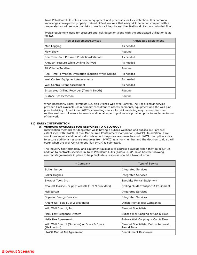
Talos Petroleum LLC utilizes proven equipment and processes for kick detection. It is common knowledge conveyed to properly trained oilfield workers that early kick detection coupled with a proper shut-in will reduce the risks to wellbore integrity and the likelihood of an uncontrolled flow.
Typical equipment used for pressure and kick detection along with the anticipated utilization is asfollows:
Anticipated DeploymentType of Equipment/Services
As neededMud Logging
RoutineFlow Show
As neededReal Time Pore Pressure Prediction/Estimate
As neededAnnular Pressure While Drilling (APWD)
RoutinePit Volume Totalizer
As neededReal Time Formation Evaluation (Logging While Drilling)
When necessary, Talos Petroleum LLC also utilizes Wild Well Control, Inc. (or a similar service provider if not available) as a primary consultant to assess personnel, equipment and the well plan prior to drilling. In addition, WWC’s consulting service for kick modeling may be used for non-routine well control events to ensure additional expert opinions are provided prior to implementation of the work.
EARLY INTERVENTION11)
VENDORS AVAILABLE FOR RESPONSE TO A BLOWOUTA)
Intervention methods for deepwater wells having a subsea wellhead and subsea BOP are wellestablished with HWCG, LLC or Marine Well Containment Corporation (MWCC). In addition, if wellconditions require additional well containment response resources beyond HWCG, the option existsto secure additional response resources from MWCC as a non-member and the decision to do so willoccur when the Well Containment Plan (WCP) is submitted.
The industry has technology and equipment available to address blowouts when they do occur. In addition to contracts specified in Talos Petroleum LLC's (Talos) OSRP, Talos has the following contracts/agreements in place to help facilitate a response should a blowout occur:
Type of Service* Company
Integrated ServicesSchlumberger
Integrated ServicesBaker Hughes
Specialty Rental EquipmentBlowout Tools Inc.
Drilling Fluids Transport & EquipmentChouest Marine - Supply Vessels (1 of 9 providers)
Integrated ServicesHalliburton
Integrated ServicesSuperior Energy Services
Oilfield Rental Tool CompaniesKnight Oil Tools (1 of 2 providers)
Blowout SpecialistsWild Well Control, Inc.
Subsea Well Capping or Cap & FlowHelix Fast Response System
Subsea Well Capping or Cap & FlowHelix Use Agreement
Blowout Specialists, Debris Removal,Rental Tools
Wild Well Control (Superior) or Boots & Coots(Halliburton)
Containment ResourcesHWCG Mutual Aid Agreement
Blowout Scenario
Type of Service* Company
Well Test EquipmentPRT Rentais
MODU Access for Relief Well(s)Mutual Assistance Agreement
15-k SS Capping StackTrendsetter Use Agreement
*This list is not intended to be all inclusive and may change from time to time based upon TalosPetroleum LLC's procurement strategy; however the final contracts required for a response will be communicated in the WCP submitted along with the APD.
B) RELIEF WELL PLANNINGA final relief well plan can only be done once an event occurs and the appropriate information relative to the blowout such as; zone, depth, blowout well trajectory and flow intensity are known. It is envisioned that any relief well would be strategically located as a single well at an open water location in order to facilitate an efficient and effective intercept. Talos Petroleum LLC's relief well plan provides for a new well which would likely be directionally drilled to intersect the existing well trajectory above the flowing zone. The casing program would be similar to the proposed production well except an additional casing string may be set above the flowing zone prior to intercept.
Blowout Scenario
In accordance with NTL 2008-G04, this information is not applicable to the activities proposed herein as the subject area is within the boundaries of the Gulf of Mexico.
FUTURE G&G ACTIVITIESK)
In accordance with NTL 2008-G04, this information is not applicable to the activities proposed herein as the subject area is within the boundaries of the Gulf of Mexico.
GEOCHEMICAL INFORMATIONJ)
In accordance with NTL 2008-G04, the information in this section is not applicable to the activities proposed herein as this plan is a Development Operations Coordination Document.
TIME VS DEPTH TABLESI)
In accordance with NTL 2008-G04, this information is not applicable to this plan as it is a Development Operations Coordination Document.
STRATIGRAPHIC COLUMNH)
The proposed surface location is within 500 feet of a previously approved surface location, Plan Control No. R-6614. The high-resolution seismic lines are included with the proprietary copy of the preivously approved Shallow Hazards Assessment attached to this appendix.
HIGH RESOLUTION SEISMIC LINESG)
The proposed surface location is within 500 feet of a previously approved surface location, Plan Control No. R-6614. The previously approved Shallow Hazards Assessment is included as an attachment to this appendix.
SHALLOW HAZARDS ASSESSMENTF)
In accordance with NTL 2008-G04, this information is not applicable as the Shallow Hazards & Archaeological Report completed by John E. Chance and Associates has been previously approved in conjunction with Plan Control No. N-4248.
hazards and chemosynthetic community assessments. Additionally, the study area falls within a zone designated by
the BOEM as having a high probability of containing cultural resources (historic shipwrecks) as specified in NTLs
2005-G07 (BOEM 2005) and 2011-Joint-G01 (BOEM 2011).
This wellsite clearance assessment is based upon the interpretation of 3D seismic exploration data and high-
resolution Autonomous Underwater Vehicle (AUV) data. Subsurface depths referenced in this letter were calculated
with a fourth-order polynomial function that was derived by FMGI and is based on a checkshot survey for Viosca Knoll
Block 988 Well No. 1.
3D Seismic Frequency and Phase. Based on frequency spectra analysis of the 3D seismic data at 50% power
(within the upper 1.0 second two-way travel time below the seafloor), the frequency bandwidth for data covering
Proposed Wellsite A ranges from 12.5 to 59 Hz (Figure 1). This frequency bandwidth corresponds to a limit of
separability of about 29.0 feet, assuming a dominant frequency of 51.8 Hz and an average velocity of 6,002 ft/sec in
the shallow section. Additional details regarding the data descriptions and limitations are documented in Fugro Report
No. 2412-5003-D. Overall, the data used in this study are judged to be of adequate quality and resolution to make
an assessment of the geologic conditions and potential hazards that may constrain exploratory drilling operations
within the study area.
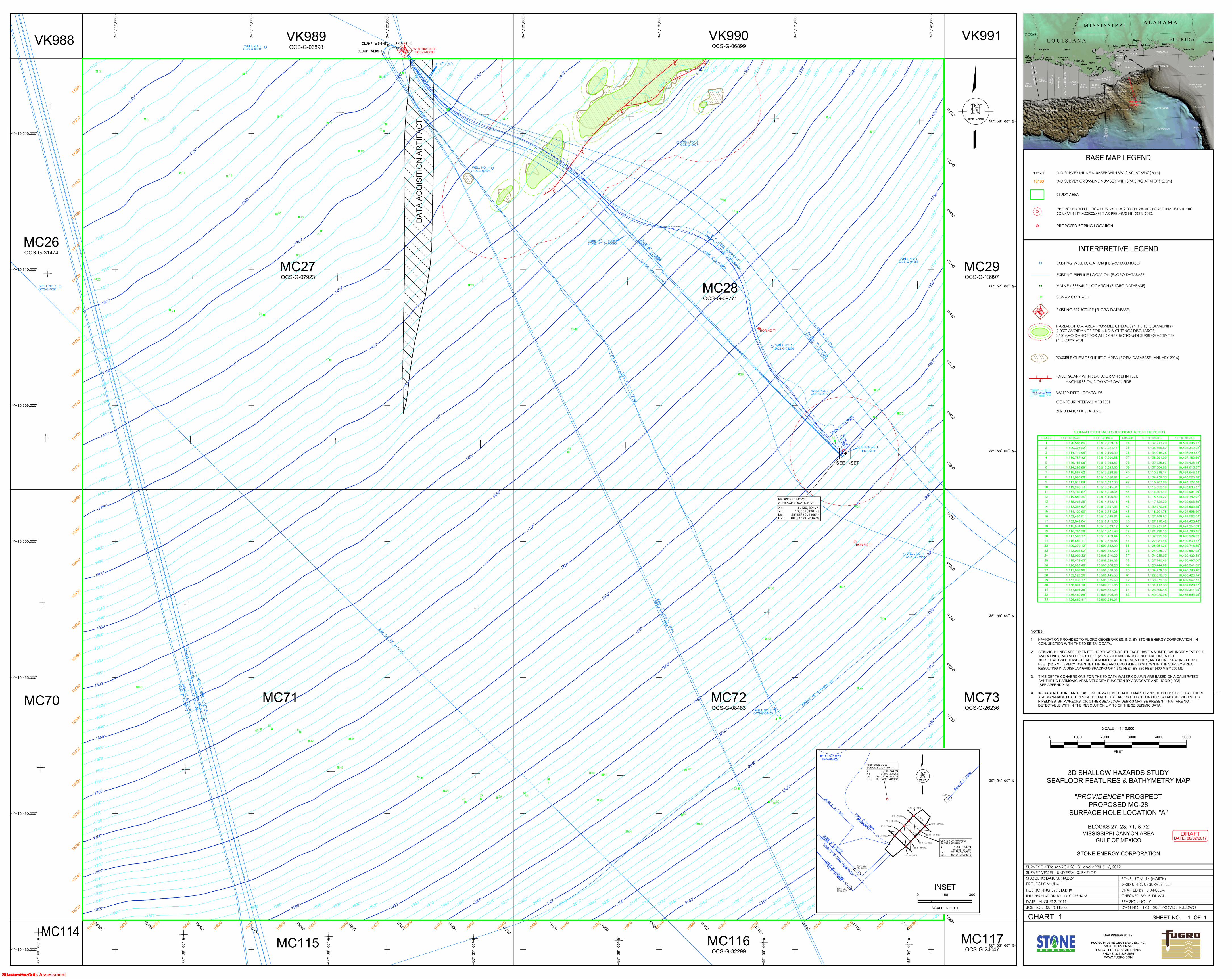
Graphics. A Seafloor Features and Bathymetry Chart (1:12,000-scale) showing the proposed wellsite, water depth
contours, man-made infrastructure, and other seafloor features accompanies this wellsite assessment. A 2,000 foot
chemosynthetic community clearance radius around the proposed wellsite is shown on the map (as per BOEM NTL
No. 2009-G40). The enclosed seismic frequency spectrum provides a sample of the 3D seismic data quality in the
vicinity of the proposed wellsite (Figure 1). An AUV side scan sonar mosaic is provided to show that the wellsite is
Attachment C-1Shallow Hazards Assessment
STONE ENERGY CORPORATION WELLSITE CLEARANCE ASSESSMENT PROVIDENCE PROSPECT, MISSISSIPPI CANYON AREA, GULF OF MEXICO
Fugro Document No. 02.17011203 Page 2 of 7
clear of potential chemosynthetic communities, archaeological resources, and man-made debris (Figure 2). An AUV
sub-bottom profiler record near the wellsite displays the seafloor conditions and a high-resolution view of the shallow
stratigraphy (Figure 3). The nearest 3D seismic inline and crossline profiles are attached to illustrate shallow geologic
conditions in the vicinity of the proposed location (Figures 4 and 5, respectively). Shallow geologic conditions at the
proposed wellsite are summarized on the attached tophole prognosis chart (Figure 6). An 8.5” x 11”, 1:12,000-scale
Subsurface Geologic Features Chart (Figure 7) is also included to illustrate geologic conditions in the vicinity of the
proposed wellbore.
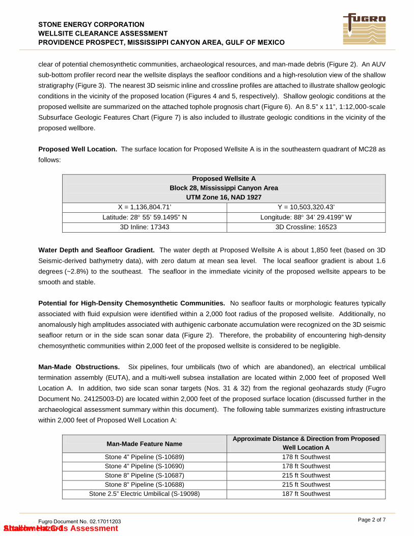
Proposed Well Location. The surface location for Proposed Wellsite A is in the southeastern quadrant of MC28 as
follows:
Proposed Wellsite A Block 28, Mississippi Canyon Area
UTM Zone 16, NAD 1927
X = 1,136,804.71’ Y = 10,503,320.43’
Latitude: 28° 55’ 59.1495” N Longitude: 88° 34’ 29.4199” W
3D Inline: 17343 3D Crossline: 16523
Water Depth and Seafloor Gradient. The water depth at Proposed Wellsite A is about 1,850 feet (based on 3D
Seismic-derived bathymetry data), with zero datum at mean sea level. The local seafloor gradient is about 1.6
degrees (~2.8%) to the southeast. The seafloor in the immediate vicinity of the proposed wellsite appears to be
smooth and stable.
Potential for High-Density Chemosynthetic Communities. No seafloor faults or morphologic features typically
associated with fluid expulsion were identified within a 2,000 foot radius of the proposed wellsite. Additionally, no
anomalously high amplitudes associated with authigenic carbonate accumulation were recognized on the 3D seismic
seafloor return or in the side scan sonar data (Figure 2). Therefore, the probability of encountering high-density
chemosynthetic communities within 2,000 feet of the proposed wellsite is considered to be negligible.
Man-Made Obstructions. Six pipelines, four umbilicals (two of which are abandoned), an electrical umbilical
termination assembly (EUTA), and a multi-well subsea installation are located within 2,000 feet of proposed Well
Location A. In addition, two side scan sonar targets (Nos. 31 & 32) from the regional geohazards study (Fugro
Document No. 24125003-D) are located within 2,000 feet of the proposed surface location (discussed further in the
archaeological assessment summary within this document). The following table summarizes existing infrastructure
within 2,000 feet of Proposed Well Location A:
Man-Made Feature Name Approximate Distance & Direction from Proposed
Well Location A
Stone 4” Pipeline (S-10689) 178 ft Southwest
Stone 4” Pipeline (S-10690) 178 ft Southwest
Stone 8” Pipeline (S-10687) 215 ft Southwest
Stone 8” Pipeline (S-10688) 215 ft Southwest
Stone 2.5” Electric Umbilical (S-19098) 187 ft Southwest
Attachment C-1Shallow Hazards Assessment
STONE ENERGY CORPORATION WELLSITE CLEARANCE ASSESSMENT PROVIDENCE PROSPECT, MISSISSIPPI CANYON AREA, GULF OF MEXICO
Fugro Document No. 02.17011203 Page 3 of 7
Stone 3.5” Hydraulic Umbilical (S-11202) 108 ft Southwest
BP 5” Hydraulic Umbilical (Abandoned) (S-11203) 160 ft Northwest
Stone 2” Electric Umbilical (Abandoned) (S-13886) 84 ft Southwest
Exxon-Mobil 12” Pipeline (S-12521) 1,512 ft Northeast
Exxon-Mobil 8” Pipeline (S-12523) 1,512 ft Northeast
Multi-well Subsea Installation 80 ft South
Electrical Umbilical Termination Assembly (EUTA) 149 ft East
The location of all existing infrastructure and debris targets should be reviewed and considered prior to lease
development activities. Extreme caution should be exercised when working in the vicinity of these features.
Mooring Considerations. Stone Energy Corporation plans to utilize a dynamically positioned (DP) drilling vessel at the
proposed wellsite; therefore, seafloor clearance for anchor locations are not addressed in this assessment.
Stratigraphy. AUV sub-bottom profiler records display about 165 feet of parallel-laminated normal marine deposits
(Figure 3). The horizons that were mapped in the regional geohazards study (Horizons 10, 20, and 30) divide the
shallow section into four stratigraphic sequences (Sequences 1 through 4) of distinct seismic character and inferred
lithology (Figures 4 and 5). Predicted depths of Horizons 10, 20, and 30 (and the intervening sequence thicknesses)
are displayed on the attached Tophole Prognosis Chart for Proposed Wellsite A (Figure 6).
Sequence 1 is about 293 feet thick at the proposed wellbore, and is interpreted to consist of parallel-stratified clays
(normal marine deposits) interbedded with thin mass transport deposits (MTDs). Sequence 2 is approximately
424 feet thick, and is divided into two subunits. The upper subunit (Sequence 2a) is 290 feet thick and is interpreted
to be composed of parallel-layered, fine grained normal marine deposits with thin, interbedded MTDs. The basal
subunit (Sequence 2b) is interpreted to be composed of parallel-laminated sand or silt-prone sediments. Sequence
3 is 855 feet thick, and is divided into three subunits. The upper subunit (referred to as Sequence 3a) is 191 feet
thick and is interpreted to contain parallel-layered, potentially silt-prone marine deposits. The central subunit
(Sequence 3b) is 568 feet thick, and is generally thought to be composed of fine-grained normal marine deposits and
stacked MTDs. The basal subunit (Sequence 3c) is 96 feet thick, and is interpreted to contain potentially
overpressured sand or silt-prone submarine channel/levee/overbank deposits. Sequence 4 is approximately 3,237
feet thick and is divided into four subunits. The uppermost subunit (Sequence 4a) is 1,299 feet thick and is interpreted
to contain fine-grained normal marine deposits with stacked mass transport deposits. The second subunit (4b) is a
733-foot thick package of parallel-stratified, mixed-lithology submarine channel-levee deposits, fine-grained normal
marine deposits, and fine-grained MTDs. The third subunit (4c) is 696 feet thick and is dominated by normal marine
deposits and stacked MTDs. The basal subunit (4d) is 509 feet thick and is interpreted to contain fine-grained normal
marine deposits and stacked MTDs to the depth of the subsurface investigation (4,809 feet below seafloor).
Fault Penetrations. The proposed wellbore will intersect two buried faults within the depth of investigation (1.5
seconds two way time or ~4,809 feet below seafloor). The fault intersections are anticipated at approximately 3,374
feet BML (5,224 feet BSS) and 4,359 feet BML (6,209 feet BSS). Although the faults are considered inactive and
should not pose a hazard to well installation activities, drilling fluid circulation interruptions should be expected when
penetrating major faults. Additional faults below the resolution of the seismic dataset may also be encountered.
Attachment C-1Shallow Hazards Assessment
STONE ENERGY CORPORATION WELLSITE CLEARANCE ASSESSMENT PROVIDENCE PROSPECT, MISSISSIPPI CANYON AREA, GULF OF MEXICO
Fugro Document No. 02.17011203 Page 4 of 7
Potential for Sub-Seafloor Gas Hydrates. No evidence of a bottom-simulating-reflector (BSR) that may indicate
the base of the gas hydrate stability (BGHS) was observed in the shallow seismic data near the proposed wellbore.
It is important to note that the presence of a BSR is not a requisite for the presence of gas hydrates, nor is a BSR
alone necessarily indicative of gas hydrates. The seismic data cannot help directly predict the distribution and quantity
of hydrates within the stability zone. However, it is reasonable to expect that accumulations of gas hydrates are more
likely to occur near accumulations of free-phase gas. If gas hydrates are present in the shallow sediments, they
would likely occur within the predominately fine-grained interval between the seafloor and the BGHS in localized and
disseminated accumulations of small crystals and nodules, lenses and partings, or thin veins. Although disseminated
gas hydrates are possible, it is unlikely that this condition would constrain exploratory drilling using a DP rig.
Potential for Free-Phase Gas Accumulations. The proposed deviated wellbore will not intersect any mapped
amplitude anomalies (which are indicative of potentially gas-charged sediments) and the shallow section is interpreted
to contain mainly fine-grained sediments; therefore, a shallow gas potential of “negligible” has been assessed
throughout the depth of investigation. However, the wellbore will penetrate sediments described as laterally
extensive, potentially coarse-grained deposits at the basal portion of Sequence 3 (designated as Sequence 3c).
Coarse-grained sediments are also likely to be encountered in Sequence 4b. The potential for encountering
unresolved sand-prone sections that may be gas-charged should be considered during well design, and appropriate
precautionary measures should be implemented. The potential for encountering shallow gas (and overpressured
water sands) within the shallow section is assessed based on open-hole conditions with no pressure control in place.
Seismic amplitude analysis is an interpretive process; therefore, any additional seismic records collected near the
proposed well location should be inspected for evidence of shallow gas. All subsurface amplitude anomalies in the
vicinity of the proposed wellbore are annotated on the attached 8.5” x 11”, 1:12,000-scale Subsurface Geologic
Features Chart (Figure 7).
Potential for Shallow Water Flow (SWF). Shallow geologic conditions are conducive for the induction and
preservation of geopressure within sand-prone deposits in the vicinity of the proposed wellbore. Based on regional
analysis, MC28 lies within a region of moderate risk for SWF (Pelletier et al, 1999). This classification is based on the
number of local SWF occurrences and their severity. A short-duration shallow water flow event was reported at the
MC29-5 well, which is located approximately 1.9 miles east-southeast of Proposed Wellsite A. The SWF event
occurred at an approximate depth of 2,881 feet BML (~5,000 feet BSS). Additionally, a shallow water flow event was
reported at the MC243-1 well, which is located approximately 20 miles southwest of the proposed wellsite. This SWF
event was reported at a depth of 1,379 feet BML (~4,184 feet BSS) with a severity of “low”. The integrity of both wells
was maintained during these SWF events.
Sediments in Sequences 1 and 2 are interpreted to consist primarily of fine-grained, normally deposited material with
low amounts of overburden; thus, the likelihood for SWF within these intervals is deemed “negligible”. Stratigraphic
Sequences 3a and 3b are primarily fine-grained and are also assessed a SWF potential of “negligible”. Sequence 3c
contains laterally extensive, potentially coarse-grained sediments that are overlain by relatively large amounts of
rapidly-deposited, fine-grained overburden; thus, the SWF potential for this interval is considered “moderate”.
Sequences 4a, 4c, and 4d contain fine-grained normal marine deposits with interbedded MTDs and have been
assessed a SWF potential of “low” due to the possibility of encountering unresolved, overpressured sand lenses.
Sequence 4b is (at least partially) composed of potentially coarse-grained channel-levee deposits that are overlain
Attachment C-1Shallow Hazards Assessment
STONE ENERGY CORPORATION WELLSITE CLEARANCE ASSESSMENT PROVIDENCE PROSPECT, MISSISSIPPI CANYON AREA, GULF OF MEXICO
Fugro Document No. 02.17011203
Page 5 of 7
by large amounts of rapidly-deposited overburden. This interval is assessed a SWF potential of “moderate” due to
the possibility of encountering sandy sediments as well as its general stratigraphic correlation to the SWF interval that
was penetrated during the installation of offset well MC29-5.
The casing and drilling mud programs for Proposed Location A should be designed to mitigate potential shallow water
flow problems in the intervals outlined above. Additionally, the possibility of encountering unresolved, unconsolidated,
and overpressured sand lenses at this location should be carefully considered and incorporated into wellbore design.
Real-time remotely operated vehicle (ROV) monitoring of the wellhead at the seafloor is recommended while drilling
the riserless section to provide an early warning of potential shallow water flow problems. Furthermore, the drilling
contractor should maintain an adequate supply of kill mud to maintain control of the well in the event that a SWF
problem occurs.
Archaeological Assessment. Findings submitted in this archaeological assessment are based on the interpretation
of AUV side scan sonar and AUV bathymetric data sets. Fugro acquired the high-resolution geophysical survey data
utilizing a Bluefin AUV aboard the Universal Surveyor from March 28–31 and from April 5–6, 2012. The quality of the
collected geophysical data was excellent, and the data were suitable for interpretation. Horizontal positioning of the
survey vessel was accomplished with the Fugro Starfix Differential Global Positioning System, which has a field
accuracy of ±1 meter. The AUV navigates using GPS while on the surface and an inertial navigation system (INS)
coupled with a Doppler velocity logger when submerged. In addition, the AUV was tracked with an Ultra Short Base
Line (USBL) system and sent position updates via an acoustic modem to continually augment the INS navigation.
The AUV performed pre-programmed survey missions collecting 200 kHz multibeam bathymetry and 120 and 410 kHz
chirp side scan sonar data.
The survey grid consisted of 33 primary west-east tracklines (Lines 300–332) spaced 300m apart, and 11 north–south
tie lines (Lines 400–410) spaced 900m apart. Navigational fixes (shot points) were recorded at 410 foot (125 m)
intervals. The survey records provided complete seafloor coverage with the side scan sonar system. At the request
of Stone Energy Corporation, the AUV survey grid was not designed to provide 100% MBES seafloor coverage;
therefore, MBES data gaps of approximately 76 meters (250 feet) exist between primary tracklines and up to 111
meters (365 feet) at the northern and southern survey edges. During data acquisition, the AUV was maintained at an
altitude of 42 meters above the seafloor. For additional information concerning this AUV survey, please refer to Fugro
Document No. 2412-5003-D. The archaeological assessment of the proposed well location is summarized below:
• This Archaeological Assessment was written to satisfy the Bureau of Ocean Energy Management/Bureau of
Safety and Environmental Enforcement (BOEM/BSEE) regulations set forth by NTLs 2005-G07 and 2011-JOINT-
G01.
• The regional probability for shipwrecks in this area is considered to be moderate; preservation of a wreck would
be moderate to good (Pearson et al. 2003). Analyses of available shipwreck sources, as well as the Fugro
Chance database, indicate that no shipwrecks have been reported in the vicinity of the proposed well location.
• The seafloor within close proximity to the proposed “A” surface location is relatively flat and featureless.
• The water depth at the proposed “A” surface location is approximately -1,850 feet, with zero datum at mean sea
level.
Attachment C-1Shallow Hazards Assessment
STONE ENERGY CORPORATION WELLSITE CLEARANCE ASSESSMENT PROVIDENCE PROSPECT, MISSISSIPPI CANYON AREA, GULF OF MEXICO
Fugro Document No. 02.17011203 Page 6 of 7
• There are no seafloor mounds, expulsion features, or hard-bottom areas located within 2,000 feet of the proposed
“A” surface location.
• There were no irregular seafloor features identified on the multibeam bathymetry data that could represent
unidentified shipwreck remains.
• In general, the side scan sonar images exhibit moderate reflectivity, which is indicative of relatively homogenous,
fine-grained seafloor sediments.
• Sixty-five sonar contacts were recorded in the regional study area (Fugro Document No. 2412-5003-D). None of
the contacts were deemed to be archaeologically significant.
• Two side scan sonar contacts (Nos. 31 and 32) were noted within 2,000 feet of the proposed “A” surface location. Neither contact is considered to be archaeologically significant; therefore, an archaeological avoidance is not recommended. Sonar Contact No. 31 is located approximately 1,667 feet to the northeast of the proposed location. Sonar Contact No. 32 is located approximately 517 feet to the northwest of the proposed well location. Both contacts were classified as modern anthropogenic debris.
The evaluation of the high-resolution geophysical survey data indicates that there were no unusual depressions,
scours, sediment changes, or unidentified seafloor targets observed within the survey area that could represent
unidentified shipwreck remains.
It is possible that small features representing high probability areas for prehistoric archaeological sites and historic
shipwreck materials may not be detected by the geophysical instruments or may not be detected during interpretation
of the data. If evidence of historic cultural remains is encountered during subsequent work, the BOEM/BSEE
archaeologists must be contacted within 48 hours to provide an assessment of these artifacts, and all operations must
cease within 1,000 feet of the exposed objects.
Closing. We appreciate the opportunity to work with you on this project and look forward to continuing as your
geohazards consultants. If you have any questions concerning this assessment, please do not hesitate to call me
(337-268-3237).
Sincerely,
FUGRO MARINE GEOSERVICES, INC.
Dean Gresham Deputy Geoscience Group Manager
Ray Blackmon Supervising Marine Archaeologist
Attachment C-1Shallow Hazards Assessment
Attachment C-1Shallow Hazards Assessment
AutoCAD SHX Text
N
AutoCAD SHX Text
GRID NORTH
AutoCAD SHX Text
CLUMP WEIGHT
AutoCAD SHX Text
CLUMP WEIGHT
AutoCAD SHX Text
LARGE TIRE
AutoCAD SHX Text
Chevron 12" S-11870
AutoCAD SHX Text
Walter 4" S-15903
AutoCAD SHX Text
LLOG 2" S-17770
AutoCAD SHX Text
LLOG 4"-6" S-17769
AutoCAD SHX Text
Walter 2" Umb S-15904
AutoCAD SHX Text
Williams 18" S-17901, etc
AutoCAD SHX Text
Chevron 5" S-12190
AutoCAD SHX Text
Noble 1" UMB S-17716
AutoCAD SHX Text
-Y=10,485,000'
AutoCAD SHX Text
X=1,110,000'-
AutoCAD SHX Text
X=1,115,000'-
AutoCAD SHX Text
X=1,120,000'-
AutoCAD SHX Text
X=1,125,000'-
AutoCAD SHX Text
X=1,130,000'-
AutoCAD SHX Text
X=1,135,000'-
AutoCAD SHX Text
X=1,140,000'-
AutoCAD SHX Text
-Y=10,490,000'
AutoCAD SHX Text
-Y=10,495,000'
AutoCAD SHX Text
-Y=10,500,000'
AutoCAD SHX Text
-Y=10,505,000'
AutoCAD SHX Text
-Y=10,510,000'
AutoCAD SHX Text
-Y=10,515,000'
AutoCAD SHX Text
28° 53' 00" N-
AutoCAD SHX Text
-88° 40' 00" W
AutoCAD SHX Text
-88° 39' 00" W
AutoCAD SHX Text
-88° 38' 00" W
AutoCAD SHX Text
-88° 37' 00" W
AutoCAD SHX Text
-88° 36' 00" W
AutoCAD SHX Text
-88° 35' 00" W
AutoCAD SHX Text
-88° 34' 00" W
AutoCAD SHX Text
28° 54' 00" N-
AutoCAD SHX Text
28° 55' 00" N-
AutoCAD SHX Text
28° 56' 00" N-
AutoCAD SHX Text
28° 57' 00" N-
AutoCAD SHX Text
28° 58' 00" N-
AutoCAD SHX Text
Noble 4" S-18176
AutoCAD SHX Text
Noble 4" S-18177
AutoCAD SHX Text
Chevron 12" S-11871
AutoCAD SHX Text
Shell P/L 18" S-13543
AutoCAD SHX Text
Ex-Mob 8" S-12520
AutoCAD SHX Text
Ex-Mob 8" S-12523
AutoCAD SHX Text
Ex-Mob 12" S-12521
AutoCAD SHX Text
Ex-Mob UMB S-12522
AutoCAD SHX Text
BP 3" S-13886
AutoCAD SHX Text
BP 2" S-11202
AutoCAD SHX Text
BP 5" S-11203
AutoCAD SHX Text
BP 8" S-10687
AutoCAD SHX Text
BP 8" S-10688
AutoCAD SHX Text
BP 4" S-10690
AutoCAD SHX Text
BP 4" S-10689
AutoCAD SHX Text
BP 2" P/L's
AutoCAD SHX Text
"A"
AutoCAD SHX Text
JKT @ MUD (-1288')
AutoCAD SHX Text
DECK (+102')
AutoCAD SHX Text
FLARE
AutoCAD SHX Text
CRANE
AutoCAD SHX Text
CRANE
AutoCAD SHX Text
(APPROX.)
AutoCAD SHX Text
5'
AutoCAD SHX Text
2'
AutoCAD SHX Text
5'
AutoCAD SHX Text
4'
AutoCAD SHX Text
3'
AutoCAD SHX Text
1'
AutoCAD SHX Text
1'
AutoCAD SHX Text
Pascagoula
AutoCAD SHX Text
Gulfport
AutoCAD SHX Text
Biloxi
AutoCAD SHX Text
Mobile
AutoCAD SHX Text
Port
AutoCAD SHX Text
Arthur
AutoCAD SHX Text
Sabine Pass
AutoCAD SHX Text
Cameron
AutoCAD SHX Text
Grand Cheniere
AutoCAD SHX Text
Intracoastal City
AutoCAD SHX Text
Fresh Water City
AutoCAD SHX Text
Morgan City
AutoCAD SHX Text
Amelia
AutoCAD SHX Text
Houma
AutoCAD SHX Text
Dulac
AutoCAD SHX Text
Grand
AutoCAD SHX Text
Isle
AutoCAD SHX Text
Fourchon
AutoCAD SHX Text
Lake Charles
AutoCAD SHX Text
Lafayette
AutoCAD SHX Text
Pensacola
AutoCAD SHX Text
Destin
AutoCAD SHX Text
Panama City
AutoCAD SHX Text
Apalachicola
AutoCAD SHX Text
Tallahassee
AutoCAD SHX Text
Gulf Shores
AutoCAD SHX Text
New Orleans
AutoCAD SHX Text
Venice
AutoCAD SHX Text
5'
AutoCAD SHX Text
"A"
AutoCAD SHX Text
JKT @ MUD (-1288')
AutoCAD SHX Text
DECK (+102')
AutoCAD SHX Text
FLARE
AutoCAD SHX Text
CRANE
AutoCAD SHX Text
CRANE
AutoCAD SHX Text
(APPROX.)
AutoCAD SHX Text
1
AutoCAD SHX Text
10,517,219.14'
AutoCAD SHX Text
1,120,586.84'
AutoCAD SHX Text
2
AutoCAD SHX Text
10,517,284.11'
AutoCAD SHX Text
1,109,323.22'
AutoCAD SHX Text
3
AutoCAD SHX Text
10,517,196.30'
AutoCAD SHX Text
1,114,719.95'
AutoCAD SHX Text
4
AutoCAD SHX Text
10,517,096.58'
AutoCAD SHX Text
1,119,757.42'
AutoCAD SHX Text
5
AutoCAD SHX Text
10,515,598.82'
AutoCAD SHX Text
1,136,164.06'
AutoCAD SHX Text
6
AutoCAD SHX Text
10,515,543.85'
AutoCAD SHX Text
1,124,298.89'
AutoCAD SHX Text
7
AutoCAD SHX Text
10,515,628.99'
AutoCAD SHX Text
1,115,997.62'
AutoCAD SHX Text
8
AutoCAD SHX Text
10,515,528.91'
AutoCAD SHX Text
1,111,095.08'
AutoCAD SHX Text
9
AutoCAD SHX Text
10,515,397.33'
AutoCAD SHX Text
1,117,815.89'
AutoCAD SHX Text
10
AutoCAD SHX Text
10,515,345.31'
AutoCAD SHX Text
1,119,966.73'
AutoCAD SHX Text
11
AutoCAD SHX Text
10,515,068.34'
AutoCAD SHX Text
1,137,782.87'
AutoCAD SHX Text
12
AutoCAD SHX Text
10,515,100.59'
AutoCAD SHX Text
1,119,880.24'
AutoCAD SHX Text
13
AutoCAD SHX Text
10,514,362.16'
AutoCAD SHX Text
1,118,964.25'
AutoCAD SHX Text
14
AutoCAD SHX Text
10,513,557.51'
AutoCAD SHX Text
1,112,397.62'
AutoCAD SHX Text
15
AutoCAD SHX Text
10,513,431.26'
AutoCAD SHX Text
1,114,120.90'
AutoCAD SHX Text
16
AutoCAD SHX Text
10,512,549.81'
AutoCAD SHX Text
1,132,403.51'
AutoCAD SHX Text
17
AutoCAD SHX Text
10,512,115.63'
AutoCAD SHX Text
1,132,849.04'
AutoCAD SHX Text
18
AutoCAD SHX Text
10,512,039.12'
AutoCAD SHX Text
1,115,934.98'
AutoCAD SHX Text
19
AutoCAD SHX Text
10,511,931.46'
AutoCAD SHX Text
1,116,763.20'
AutoCAD SHX Text
20
AutoCAD SHX Text
10,511,419.44'
AutoCAD SHX Text
1,117,568.77'
AutoCAD SHX Text
21
AutoCAD SHX Text
10,510,525.86'
AutoCAD SHX Text
1,116,687.11'
AutoCAD SHX Text
22
AutoCAD SHX Text
10,509,652.90'
AutoCAD SHX Text
1,109,279.12'
AutoCAD SHX Text
23
AutoCAD SHX Text
10,509,432.20'
AutoCAD SHX Text
1,123,004.02'
AutoCAD SHX Text
24
AutoCAD SHX Text
10,508,510.20'
AutoCAD SHX Text
1,112,009.32'
AutoCAD SHX Text
25
AutoCAD SHX Text
10,508,328.06'
AutoCAD SHX Text
1,115,472.63'
AutoCAD SHX Text
26
AutoCAD SHX Text
10,507,808.23'
AutoCAD SHX Text
1,126,953.48'
AutoCAD SHX Text
27
AutoCAD SHX Text
10,506,678.55'
AutoCAD SHX Text
1,117,908.96'
AutoCAD SHX Text
28
AutoCAD SHX Text
10,506,145.53'
AutoCAD SHX Text
1,132,926.26'
AutoCAD SHX Text
29
AutoCAD SHX Text
10,505,575.60'
AutoCAD SHX Text
1,137,935.17'
AutoCAD SHX Text
30
AutoCAD SHX Text
10,504,711.05'
AutoCAD SHX Text
1,138,801.10'
AutoCAD SHX Text
31
AutoCAD SHX Text
10,504,584.29'
AutoCAD SHX Text
1,137,894.38'
AutoCAD SHX Text
32
AutoCAD SHX Text
10,503,709.93'
AutoCAD SHX Text
1,136,460.88'
AutoCAD SHX Text
33
AutoCAD SHX Text
10,503,286.91'
AutoCAD SHX Text
1,126,660.41'
AutoCAD SHX Text
34
AutoCAD SHX Text
10,501,296.77'
AutoCAD SHX Text
1,137,217.20'
AutoCAD SHX Text
35
AutoCAD SHX Text
10,498,340.02'
AutoCAD SHX Text
1,136,669.87'
AutoCAD SHX Text
36
AutoCAD SHX Text
10,498,290.37'
AutoCAD SHX Text
1,134,048.26'
AutoCAD SHX Text
37
AutoCAD SHX Text
10,497,152.59'
AutoCAD SHX Text
1,138,291.00'
AutoCAD SHX Text
38
AutoCAD SHX Text
10,496,428.19'
AutoCAD SHX Text
1,133,936.62'
AutoCAD SHX Text
39
AutoCAD SHX Text
10,494,613.57'
AutoCAD SHX Text
1,137,304.66'
AutoCAD SHX Text
40
AutoCAD SHX Text
10,494,649.33'
AutoCAD SHX Text
1,110,819.14'
AutoCAD SHX Text
41
AutoCAD SHX Text
10,493,520.78'
AutoCAD SHX Text
1,134,439.33'
AutoCAD SHX Text
42
AutoCAD SHX Text
10,493,122.38'
AutoCAD SHX Text
1,115,763.88'
AutoCAD SHX Text
43
AutoCAD SHX Text
10,493,093.37'
AutoCAD SHX Text
1,115,352.96'
AutoCAD SHX Text
44
AutoCAD SHX Text
10,492,991.29'
AutoCAD SHX Text
1,116,801.49'
AutoCAD SHX Text
45
AutoCAD SHX Text
10,492,752.97'
AutoCAD SHX Text
1,118,624.22'
AutoCAD SHX Text
46
AutoCAD SHX Text
10,492,668.59'
AutoCAD SHX Text
1,117,129.20'
AutoCAD SHX Text
47
AutoCAD SHX Text
10,491,609.55'
AutoCAD SHX Text
1,130,970.96'
AutoCAD SHX Text
48
AutoCAD SHX Text
10,491,698.50'
AutoCAD SHX Text
1,118,201.78'
AutoCAD SHX Text
49
AutoCAD SHX Text
10,491,502.53'
AutoCAD SHX Text
1,127,469.82'
AutoCAD SHX Text
50
AutoCAD SHX Text
10,491,428.48'
AutoCAD SHX Text
1,127,916.42'
AutoCAD SHX Text
51
AutoCAD SHX Text
10,491,257.09'
AutoCAD SHX Text
1,125,931.81'
AutoCAD SHX Text
52
AutoCAD SHX Text
10,491,308.95'
AutoCAD SHX Text
1,121,290.15'
AutoCAD SHX Text
53
AutoCAD SHX Text
10,490,924.62'
AutoCAD SHX Text
1,132,925.88'
AutoCAD SHX Text
54
AutoCAD SHX Text
10,490,839.72'
AutoCAD SHX Text
1,122,081.46'
AutoCAD SHX Text
55
AutoCAD SHX Text
10,490,748.80'
AutoCAD SHX Text
1,125,051.26'
AutoCAD SHX Text
56
AutoCAD SHX Text
10,490,587.08'
AutoCAD SHX Text
1,124,026.77'
AutoCAD SHX Text
57
AutoCAD SHX Text
10,490,429.36'
AutoCAD SHX Text
1,134,035.93'
AutoCAD SHX Text
58
AutoCAD SHX Text
10,490,497.00'
AutoCAD SHX Text
1,127,740.49'
AutoCAD SHX Text
59
AutoCAD SHX Text
10,490,541.55'
AutoCAD SHX Text
1,123,444.66'
AutoCAD SHX Text
60
AutoCAD SHX Text
10,490,380.40'
AutoCAD SHX Text
1,134,239.10'
AutoCAD SHX Text
61
AutoCAD SHX Text
10,490,429.14'
AutoCAD SHX Text
1,122,878.70'
AutoCAD SHX Text
62
AutoCAD SHX Text
10,489,947.32'
AutoCAD SHX Text
1,130,832.70'
AutoCAD SHX Text
63
AutoCAD SHX Text
10,489,628.57'
AutoCAD SHX Text
1,131,413.33'
AutoCAD SHX Text
64
AutoCAD SHX Text
10,489,341.25'
AutoCAD SHX Text
1,128,806.48'
AutoCAD SHX Text
65
AutoCAD SHX Text
10,486,693.95'
AutoCAD SHX Text
1,140,020.98'
greshamd
Rectangle
In accordance with NTL 2008-G04, this information is not applicable to this plan as Talos Petroleum does not anticipate encountering H2S during the activities proposed herein.
MODELING REPORTD)
In accordance with NTL 2008-G04, this information is not applicable to this plan as Talos Petroleum does not anticipate encountering H2S during the activities proposed herein.
H2S CONTINGENCY PLANC)
PROPRIETARY INFORMATION
In accordance with 30 CFR 250.490(c), Talos Petroleum is requesting the subject area and block, and lease(s), respectively be classified by the DOI as an area absent of H2S. This is based upon information from the well(s) listed in the table below.
CLASSIFICATIONB)
In accordance with NTL 2008-G04, this information is not applicable to this plan as Talos Petroleum does not anticipate encountering any H2S during the operations proposed herein.
Endangered marine mammal species as listed under the Endangered Species Act that might occur in the Gulf of Mexico are the Gulf of Mexico Bryde’s Whale (Balaenoptera edeni), Oceanic Whitetip Shark (Carcharhinus longimanus), Giant Manta Ray (Manta birostris), West Indian manatee (Trichechus manatus), northern right whale (Eubalaena glacialis), fin whale (Balaenoptera physalus), humpback whale (Megaptera novaiangliae), sei whale (Balaenoptera borealis), sperm whale (Physeter macrocephalus), and blue whale (Balaenoptera musculus). Endangered or threatened sea turtle species that might occur in the Gulf of Mexico are Kemp’s ridley (Lepidochelys kempii), green turtle (Chelonia mydas), hawksbill (Eretmochelys imbricate), leatherback (Demochelys coriacea), and loggerhead (Caretta caretta) (USDOI, OCS EIS/EA MMS 2007-2012). The only listed threatened fish species in the Gulf of Mexico is the Gulf sturgeon (Ancipenser oxyrincus desotoi).
The subject area(s) and block(s) is not designated as a critical habitat for any of these species. Talos Energy does not anticipate that any threatened or endangered species will be adversely affected as a result of the activities proposed herein. However, in the unlikely event of an accident, adverse impacts to endangered marine mammal species are possible.
Talos will adhere to the requirements as set forth in the following Notices to Lessees and guidelines, as applicable, to avoid or minimize impacts to any of the species listed in the ESA as a result of the operations conducted herein:
· NTL 2015-G03 "Marine Trash and Debris Awareness and Elimination"· BOEM NTL 2016-G01 "Vessel Strike Avoidance and Injured/ Dead Protected Species Reporting· BOEM NTL 2016-G02 "Implementation of Seismic Survey Mitigation Measures and Protected Species
Observer Program" · Appendix A: Seismic Survey Mitigation and Protected Species Observer Protocols, found in the
Biological Opinion issued by the National Marine Fisheries Service on March 13, 2020· Appendix B: Gulf of Mexico Marine Trash and Debris Awareness and Elimination Survey
Protocols, found in the Biological Opinion issued by the National Marine Fisheries Service on March
In accordance with NTL 2009-G39. this information is not applicable to the activities proposed herein as the bottom-disturbing activities are not within 100 feet of potentially sensitive biological features.
POTENTIALLY SENSITIVE BIOLOGICAL FEATURESF)
In accordance with NTL 2008-G04, this information is not applicable to the activities proposed herein as the Live Bottom (Low Relief) lease stipulation is not attached to the subject lease(s).
LIVE BOTTOM (LOW RELIEF) MAPE)
In accordance with NTL 2008-G04, this information is not applicable to the activities proposed herein as the Live Bottom (Pinnacle Trend) lease stipulation is not attached to the subject lease(s).
LIVE BOTTOM (PINNACLE TREND) MAPD)
In accordance with NTL 2008-G04, this information is not applicable to the activities proposed herein as this is a Development Operations Coordination Document.
TOPOGRAPHIC FEATURES STATEMENT (SHUNTING)C)
In accordance with NTL 2008-G04, this information is not applicable to the activities proposed herein as no rig, barge or anchors,etc. will be placed within 1,000 feet of the "No Activity Zone" of an identified topographic feature.
TOPOGRAPHIC FEATURES MAPB)
A shallow hazards and archaeological assessment was conducted and approved under plan control number N-4248. As referenced in that document, no impacts to benthic communities expected in the proposed project location.
Additionally, a wellsite clearance letter and map(s) was provided for under Plan Control No. R-6614 and is included as an attachment to Appendix C of this plan. As referenced in that document, no seafloor faults or morphologic features typically associated with fluid expulsion were identified within a 2,000 foot raduis of the proposed wellsite. Accordingly, the probability of encountering benthic communities within 200 feet of the proposed wellsite is considered negligible.
A map depicting the proposed surface location and subsurface geologic features are included in the attachment to this appendix.
CHEMOSYNTHETIC COMMUNITIES REPORTA)
APPENDIX FBIOLOGICAL, PHYSICAL, & SOCIOECONOMIC INFORMATION
In accordance with NTL 2008-G04, this information is not applicable to the activities proposed herein as the State of Florida is not an affected State.
SOCIOECONOMIC INFORMATIONJ)
In accordance with NTL 2008-G04, this information is not applicable to the activities proposed herein as the State of Florida is not an affected State.
AIR & WATER QUALITY INFORMATIONI)
A shallow hazards and archaeological assessment was conducted and approved under plan control number N-4248. As referenced in that document, no impacts to shipwrecks or archaeologically significant features are expected in the proposed project location.
ARCHAEOLOGICAL REPORTH)
13, 2020· Appendix C: Gulf of Mexico Vessel Strike Avoidance and lnjured/Dead Aquatic Protected Species
Reporting Protocols, found in the Biological Opinion issued by the National Marine Fisheries Service on March 13, 2020
· Appendix J: Sea Turtle Handling and Resuscitation Guidelines, found in the Biological Opinion issued by the National Marine Fisheries Service on March 13, 2020
In accordance with NTL 2008-G04, this information is not applicable to the activities proposed herein as the associated leases are within the Gulf of Mexico Region.
COOLING WATER INTAKESE)
The subject rig and/or facility will be covered under Talos Petroleum's General Permit upon commencement of the activities proposed herein.
NPDES PERMITSD)
In accordance with NTL 2008-G04, this information is not applicable to the activities proposed herein as the subject activities do not require an individual NPDES permit. Therefore, a modeling report is not mandated.
MODELING REPORTC)
In accordance with 30 CFR 250.217 and 30 CFR 250.248, information must be provided on all projected solid and liquid wastes likely to be generated by an operator’s proposed activities including operational wastes permitted by the appropriate NPDES permit and any other identified wastes. Attached to this appendix is Table 2 entitled “Wastes you will transport and/or dispose of onshore” which satisfies the requirements set forth by NTL 2008-G04 and the aforementioned CFRs.
PROJECTED OCEAN DISCHARGESB)
In accordance with 30 CFR 250.217 and 30 CFR 250.248, information must be provided on all projected solid and liquid wastes likely to be generated by an operator’s proposed activities including operational wastes permitted by the appropriate NPDES permit and any other identified wastes. Attached to this appendix is Table 1 entitled “Wastes you will generate, treat and downhole dispose or discharge to the GOM” which satisfies the requirements set forth by NTL 2008-G04 and the aforementioned CFRs.
Type of Waste Composition Projected Amount Discharge rate Discharge Method Answer yes or noWill drilling occur ? If yes, you should list muds and cuttings Yes
EXAMPLE: Cuttings wetted with synthetic based fluid
Cuttings generated while using synthetic based drilling fluid. X bbl/well X bbl/day/well discharge overboard No
Water-based drilling fluid during riserless drilling Water based drilling fluids 40,000 bbls/well 20000 bbls/day/well discharge at mudline No
Cuttings wetted with water-based fluid during riserless drilling
Cuttings generated while using water based drilling fluids 3324 bbls/well 1662 bbls/day/well discharge at mudline No
Cuttings wetted with synthetic-based fluid
Cuttings generated while using synthetic based drilling fluid 3770 bbls/well 251 bbls/day/well
dried & discharge overboard No
Will humans be there? If yes, expect conventional waste
EXAMPLE: Sanitary waste waterSanitary waste from living quarters X bbl/well X bbl/hr/well
chlorinate and discharge overboard No
Domestic waste (treated) grey water 8256 bbls/well 4.3 bbls/hr/wellUSCG approved MSD with chlorination and discharged No
Sanitary waste (treated) treated sanitary waste 10944 bbls/well 5.7 bbls/hr/wellUSCG approved MSD with chlorination and discharged No
Is there a deck? If yes, there will be Deck Drainage
Deck Drainagewashwater and deck drainage 3206 bbls/well 1.67 bbls/hr/well discharge overboard No
Will you conduct well treatment, completion, or workover?
Well treatment fluids Frac Fluids 300 bbls/well300 bbls/day for 1 day/well discharge overboard NA
Well completion fluids Calcium Bromide 500 bbls/well250 bbls/day for 2 days/well discharge overboard NA
Workover fluids NA NA NA NA NA
Miscellaneous discharges. If yes, only fill in those associated with your activity.
Desalinization unit discharge Seawater 954,080 bbls/well 11,926 bpd discharge overboard NA
Blowout prevent fluidWater-based hydraulic control fluid 57 bbls/well 0.55 bbls/day
discharged from vent ports on BOP stack NA
Ballast water (uncontaminated) Seawater 41,200 bbls/well 400 bbls/day per MARPOL regulations NA
Rig Wash Water Fresh Water & Soap 5150 bbls/well 50 bbls/day discharge overboard NA
Bilge water (uncontaminated) Freshwater or Seawater 3360 bbls/well 42 bbls/day discharge overboard NA
Excess cement at seafloorWater, CaCl Class H cement & rheological modifiers 800 bbls/well
800 bbls/day for 1 day/well discharge overboard NA
Cement SpacerWater base fluid, viscosifier, barite & gel 100 bbls/well
100 bbls/day for 1 day/well discharge overboard NA
Fire water Seawater NA NA discharge overboard NA
Cooling water (uncontaminated) Seawater 73,809,360 bbls/well 922,617 bpd discharge overboard NA
Will you produce hydrocarbons? If yes fill in for produced water.
Produced water (During Well Test) NA NA NA NA NA
Will you be covered by an individual or general NPDES permit ? General Permit
NOTE: If you will not have a type of waste, enter NA in the row.
TABLE 1. WASTES YOU WILL GENERATE, TREAT AND DOWNHOLE DISPOSE OR DISCHARGE TO THE GOM - MC 28 Subsea Well 005
Projected Downhole Disposal
Table 1: Wastes you will generate, treat and downhole dispose or discharge to GOM
please specify whether the amount reported is a total or per well
Projected generated waste
Solid and Liquid Wastes transportation
Type of Waste Composition Transport Method Name/Location of Facility Amount Disposal Method
Will drilling occur ? If yes, fill in the muds and cuttings.EXAMPLE: Synthetic-based drilling fluid or mud internal olefin, ester
Below deck storage tanks on offshore support vessels
Newport Environmental Services Inc., Ingleside, TX X bbl/well Recycled
Oil-based drilling fluid or mud N/A N/A N/A N/A N/A
Synthetic-based drilling fluid or mud
Used SBM consisting of base oil (isomerized alpha olefin), barite, CaCl, Acrylate Copolymer, Limestone, Lime, and invert emulsifiers and wetting agent, assuming surface volume only
Hull Storage tanks or DOT tanks on supply vessels
Mud Vendor's Facility in Fourchon 7500 bbls/well
Returned to Mud Supplier Facility in Fourchon and reconditioned for future use
Cuttings wetted with Water-based fluid N/A N/A N/A N/A N/A
Cuttings wetted with Synthetic-based fluid
Formation cuttings, SBM Base oil (isomerized alpha olefin), barite, CaCl, Acrylate Copolymer, LCM, Limestone, Lime, and invert emulsifiers and wetting agent contaminated with formation oil
Cuttings boxes on supply vessels ECOSERV/Fourchon 500 bbls/well Recycle / Injection well
Cuttings wetted with oil-based fluids N/A N/A N/A N/A N/A
Transport to shore in drums or DOT tanks on supply vessels for disposal at an approved disposal facility
ECOSERV/Fourchon 500 bbls/well Recycle / Injection well
Wash water from mud tanksWater, surfactants & solids from mud system if zero discharge
Hull Storage tanks or DOT tanks on supply vessels
ECOSERV/Fourchon 6000 bbls/well Recycle / Injection well
Chemical Product Wastes Well Treatment Fluids Drums or tote tanks on supply vesselsEDI Environmental Services/ Lafayette LA
3 bbls/well Recycle
Chemical Product Wastes Paint & thinner waste Drums or tote tanks on supply vesselsEDI Environmental Services/ Lafayette LA
7 bbls/well Recycle
Drums of oily rags & filtersOily rags and filters impregnated with oil & grease
DOT drums transported by boat Martin Energy/Fourchon 2 drums/well Recycle
NOTE: If you will not have a type of waste, enter NA in the row.
TABLE 2. WASTES YOU WILL TRANSPORT AND /OR DISPOSE OF ONSHORE, MC 28 Well 005
Waste Disposal
Will you have additional wastes that are not permitted for discharge? If yes, fill in the appropriate rows.
Table 2: Wastes you will transport and/or dispose of onshore
Offshore air emissions related to these proposed activities result mainly from drilling operations, helicopters and vessels. These emissions occur mainly from burning fuels and natural gas and from venting or evaporation of hydrocarbons. The combustion of fuel occurs primarily on diesel-powered generators, pumps or motors and from lighter fuel motors. The primary air pollutants associated with OCS activities are nitrogen oxides, carbon monoxide, sulphuroxides, volatile organic compounds and suspended particulates. This appendix presents two (2) air emissions scenarios, one for plan emissions only and another for the platform and plan emissions.
Please note actual horsepower values for the Rowan Renaissance drillship were used in calculating the AQR.
All activities proposed herein are covered by the Regional Oil Spill Response Plan filed by Talos ERT LLC, GOM Company No. 02899, in accordance with 30 CFR 254; approved on May 4, 2017, OSRP Control No. O-647. Per letter dated July 17, 2019, Talos Petroleum LLC, BOEM Company No. 01834, is covered under this OSRP.
SPILL RESPONSE SITES2)
The table below provides information on the location of the primary spill response equipment and thelocation of the planned staging area(s) that would be used should an oil spill occur resulting from theactivities proposed herein.
Talos Petroleum’s primary equipment provider is Clean Gulf Associates (CGA). The Marine Spill Response Corporation’s (MSRC) STARS network will provide closest available personnel, as well as an MSRC supervisor to operate the equipment. CGA and MSRC have equipment pre-staged around the Gulf of Mexico. The major locations of this equipment are Lake Charles, Houma, Fort Jackson and Venice, Louisiana; Galveston and Ingleside, Texas; and Pascagoula, Mississippi.
WORST CASE SCENARIO COMPARISON4)
The table below provides a comparison of the worst-case discharge scenario from the above referencedRegional OSRP with the worst-case scenario from the activities proposed herein. Please note theRegional OSRP distance to shore scenarios are approximate and will be updated as required withmodifications to the OSRP. The distance to shore for the proposed activities is accurate and based onsurvey data.
in our Regional OSRP approved on May 4, 2017 and updated July 17, 2019. Talos has determined that theworst-case scenario from the activities proposed herein do not replace the worst-case discharge scenario from said Regional OSRP.
Talos certifies that it has the capability to respond, to the maximum extent practicable, to a worst-case discharge, or a substantial threat of such a discharge, resulting from the activities proposed herein. The WCD scenario (shown above) for this particular project is greater than 1,000 barrels per day and is based on an open hole event.
WORST CASE DISCHARGE SCENARIOS AND ASSUMPTIONS5)
Worst case discharge scenarios and assumptions were provided for under Plan Control No. R-6364.
OIL SPILL RESPONSE DISCUSSION6)
In the event of a spill at Mississippi Canyon 28, Well No. SS005, primary response would be to utilize the Oil Spill REsponse Vessels (OSRV) and Oil Spill Response Barge (OSRB) from Clean Gulf Associates (CGA). The initial response would likely be a Fast Response Vessel (FRV) located in Venice, Louisiana and the HOSS Barge located in Harvey, Louisiana. The FRV has a derated recovery capacity of 22,885 barrels/day and a storage capacity of 249 barrels. With a maximum prep time of 2.0 hours, a maximum planning run time of 3.0 hours, and a deployment time of 1.0 hour, the response vessel would be on the site in approximately 6.0 hours. The HOSS Barge has a derated recovery capacity of 76,285 barrels/day and a storage capacity of 4,100 barrels. With a maximum prep time of 6.0 hours, a maximum load out time of 1.0 hours, a maximum planning run time of 17.0 hours, and a deployment time of 1.0 hour, the response barge would be on site in approximately 25.0 hours. Additional resources would be provided from the National Response Corporation. National Response Corporation has the capabilty to have resources on scene and deployed within 24 hours.
Actual response times are generally quicker than planning times, since the vessel could be mobilized iwthin one hour, weather permitting. As with any spill, additional "cascading" response equipment would be mobilized to the site from various CGA bases such as, Leevile, LA, Harvey, LA, Venice, LA and Morgan City, LA. The staging area for Mississippi Canyon 28 Well No. SS005 will be the C-Port 2, Slip 3 in Port Fourchon, Louisiana. For spills larger than 100 barrels, dispertants may be mobilized by plane from Airborne Support, Inc. in Houma, LA, pending approval from the U.S.C.G. FOSC and RRT-6.
For planning purposes, based on worst case discharge volume coupled with the distance from shore and guidance from Clean Gulf Assoicates, it is estimated that personnel can be on-scene within 5-10 hours. It is estimated that the spill could be contained in 1.5 days and recovered within 5-7 days.
Maps identifying potential shore impact areas are included in the attachment(s) to this appendix.
ENVIRONMENTAL SENSITIVITY MAPS7)
Project WCD Environmental Sensitivity Maps for the development project area were provided for under Plan Control No. R-6364.
The Hunter development project, as proposed in this DOCD, consists of adjacent blocks Mississippi Canyon Block 28 (OCS-G 09771) and Viosca Knoll Block 989 (OCS-G 06898).
MODELING8)
In accordance with NTL 2008-G04, this information is not required for the activities proposed herein as the State of Florida is not an affected State, no surface facility is being installed in water depths greater than 1,312 feet, nor is a surface facility being installed in any water depth that supports a subsea development in water depths greater than 1,312 feet.
In accordance with NTL 2008-G04, this information is not applicable to the activities proposed herein as the subject area and block(s) are not located within the Protective Zones of the Flower Garden Banks and Stetson Bank.
FLOWER GARDEN BANKS NATIONAL MARINE SANCTUARYC)
There is no reason to believe that any of the endangered species or marine mammals as listed in the ESA will be "taken" as a result of the operations proposed under this plan.To date, it has been documented that the use of explosives and/or seismic devices can affect marine life. Operations proposed in this plan will not be utilizing either of these devices.
The proposed operations will utilize a casing hammer to drive pipe. Included as "Attachment A" to this appendix are the mitigations and protocols that Talos will adhere to while conducting impact hammer activity.
Talos does not propose any new pipelines that will make landfall.
Talos Energy will adhere to the requirements as set forth in the following Notices to Lessees and guidelines, as applicable, to avoid or minimize impacts to any of the species listed in the ESA as a result of the operations conducted herein:
NTL 2015-G03 "Marine Trash and Debris Awareness and Elimination"
BOEM NTL 2016-G01 "Vessel Strike Avoidance and Injured/ Dead Protected Species Reporting"
BOEM NTL 2016-G02 "Implementation of Seismic Survey Mitigation Measures and Protected Species Observer Program"
· Appendix A: Seismic Survey Mitigation and Protected Species Observer Protocols, found in the Biological Opinion issued by the National Marine Fisheries Service on March 13, 2020
· Appendix B: Gulf of Mexico Marine Trash and Debris Awareness and Elimination Survey Protocols, found in the Biological Opinion issued by the National Marine Fisheries Service on March 13, 2020
· Appendix C: Gulf of Mexico Vessel Strike Avoidance and lnjured/Dead Aquatic Protected Species Reporting Protocols, found in the Biological Opinion issued by the National Marine Fisheries Service on March 13, 2020
· Appendix J: Sea Turtle Handling and Resuscitation Guidelines, found in the Biological Opinion issued by the National Marine Fisheries Service on March 13, 2020
Talos will utilize a Drilling Rig with a typical moonpool that is used in all Deepwater Dynamically Positioned Drillships and Semi-submersibles. The moonpool is located on or about the center of the rig. The moonpool’s purpose is to allow access to the water level to drill, complete and workover wells. This also allows access to run the Blowout Preventers, Marine Riser and ancillary equipment to the seafloor. There is no closing mechanism for the moonpool area as it is always open to the sea.
In the extremely rare instance that marine life would get entrapped or entangled by equipment in the moonpool, or by any other equipment on the rig, below are mitigations that will be put in place to protect the marine life in case of an incident.
· Talos will provide a dedicated crew member to survey the moonpool area for marine life while moving any equipment in or out of that area.
· If marine life is detected in the moonpool area, we will cease all operations until it is free and clear. · Monitor video from the camera(s) that is focused on the moonpool area.
· If endangered marine life is seen in the area, a live video feed can be streamed real‐time for
additional coverage.· If marine life is entrapped or entangled, we can safely lower someone into the moonpool to free it.
INCIDENTAL TAKESB)
There are no environmental monitoring systems currently in place or planned for the proposed activities.
Attachment A: Impact Hammer Activity Mitigation and Protected Species Observer Protocols for Talos Petroleum LLC
The Bureau of Safety and Environmental Enforcement (BSEE) will apply these protocols and provide guidelines to operators in complying with the Endangered Species Act (ESA; 16 U.S.C. §§ 1531-1544). The measures contained herein apply to impact hammer activity proposed by Talos Petroleum LLC (hereinafter Talos) .
Background Impact hammer activities may have an impact on marine wildlife. Many marine species are protected under the Endangered Species Act (ESA) and all marine mammals are protected under the Marine Mammal Protection Act (MMPA). The following Gulf of Mexico species are listed under the ESA:
ESA-listed Species common to the Gulf of Mexico Gulf of Mexico Bryde’s Whale (Balaenoptera edeni) Sperm Whale (Physeter macrocephalus) Green Turtle (Chelonia mydas) – North Atlantic DPS and South Atlantic DPS Hawksbill Turtle (Eretmochelys imbricata) Kemp’s Ridley Turtle (Lepidochelys kempii) Leatherback Turtle (Dermochelys coriacea) - Northwest Atlantic DPS Loggerhead Turtle (Caretta caretta) – Northwest Atlantic Ocean DPS Gulf Sturgeon (Acipenser oxyrinchus desotoi) Oceanic Whitetip Shark (Carcharhinus longimanus) Giant Manta Ray (Manta birostris) West Indian Manatee (Trichechus manatus)*
*Managed by the US Fish and Wildlife Service
Note that this list can change as other species are listed/delisted, and this protocol shall be applied to any protected species that occur in the Gulf of Mexico, including rare and extralimital species, such as other ESA-listed marine mammals.
BSEE and BOEM consult jointly with the National Marine Fisheries Service (NMFS) and the U.S. Fish and Wildlife Service (FWS) under Section 7 of the ESA to ensure that BOEM- or BSEE-authorized activities do not jeopardize the continued existence of ESA-listed species nor result in destruction or adverse modification of designated critical habitat. Incidental take of ESA-listed species is prohibited except as authorized pursuant to an Incidental Take Statement in the attached Biological Opinion.
These protocols are the result of coordination between BOEM, BSEE, and NMFS and are based on: past and present mitigation measures; terms and conditions and reasonable and
2
prudent measures identified in the 2020 Biological Opinion issued to the Bureaus; and NMFS’ technical memorandum on standards for a protected species observer and data management program (Baker et al. 2013). BSEE is tasked as the lead agency for compiling lessee or operator reporting data required under current Biological Opinions applicable to both Bureaus.
In order to protect ESA-listed species and marine mammals during impact hammer operations, Talos will be required to use dedicated and trained protected species observers (PSOs) and follow specific impact hammer survey protocols when operating. Since hammer operations are estimated to take from 8 – 14 hours to complete, Talos must have at least 2 PSOs to allow for shifts/requisite breaks (see PSO Visual Monitoring Requirements below). Talos must demonstrate compliance with these requirements by submitting to BSEE certain reports as detailed below.
Definitions Terms used in these protocols have the following meanings:
1. Protected species means any species listed under the ESA and/or protected by the MMPA. The requirements discussed herein focus on marine mammals and sea turtles since these species are the most likely to be observed during impact hammer activities. However, all observations of marine mammals and ESA-listed species (see table above) should be reported as detailed below in Reporting Requirements.
2. Impact hammer activity means activities that utilize the Hydrohammer® S-150 impact hammer for the setting of the conductor/outer casing as proposed by Talos in their AST.
3. Soft start (sometimes referred to as "ramp-up") means the gradual and systematic increase of emitted sound levels from an impact hammer activity. Soft start begins by first performing an initial set of strikes from the impact hammer at reduced energy level. The use of a soft start procedure is believed to provide additional protection to protected species by “warning” or providing them a chance to leave the area prior to the hammer operating at full capacity.
4. Operational level means the highest energy level at which the impact hammer will operate for the majority of the impact hammer activity. The strikes from the impact hammer at operational level will be a higher energy level than the initial strikes during soft start.
5. Shutdown means the immediate cessation of the impact hammer strikes when technically feasible, as described below in General Requirements.
6. Exclusion zone means the area to be monitored for pre-clearance and possible mitigation actions (such as delays to soft start) in order to reduce or eliminate the potential for injury of protected species. The exclusion zone encompasses the area at and below the sea surface out to a radius of 157 meters (m), or 515 feet (ft) from the impact hammer activity.
3
7. Pre-clearance means the visual monitoring of the exclusion zone for protected species to determine if the zone has been clear of protected species for at least 30 minutes before the soft start may begin. Visual monitoring should extend beyond the exclusion zone for detecting protected species that may be traveling to or entering the exclusion zone.
8. Visual monitoring means the use of trained personnel (herein referred to as PSOs) to scan the ocean surface visually for the presence of protected species. Visual monitoring of the exclusion zones and adjacent waters is intended to establish and maintain zones around the impact hammer activity that are clear of protected species, thereby reducing or eliminating the potential for injury. Visual monitoring of adjacent waters is intended to aid in establishing and maintaining the exclusion zone by alerting all relevant personnel of protected species that are outside of, but may approach and enter, the exclusion zone.
General Requirements 1. A copy of this Attachment must be in the possession of the platform operator, other
relevant personnel, the PSOs, and any other relevant designees operating under the authority of the approved AST.
2. Talos shall instruct relevant personnel (including applicable rig and platform personnel) with regard to the authority of the PSOs, and shall ensure that relevant personnel and the PSOs participate in all pre-operation briefings (JSA/JSEA meetings) to ensure that responsibilities, communication procedures, protected species monitoring protocols, operational procedures, and permit requirements are clearly understood. This briefing procedure must be repeated at each shift change and JSA/JSEA meeting, before work commences or recommences.
3. The PSOs must be granted access to relevant instrumentation to document real-time hammer log information.
4. The PSOs must be granted access to the most appropriate observation posts to safely conduct visual monitoring of the exclusion zone. The observation posts should provide an unobstructed view of the zone to the maximum extent practicable.
5. Hammer/conductor driving activities will not begin during nighttime or periods of reduced visibility (e.g., fog, heavy rain, unfavorable sea state, etc.) in which a PSO cannot observe the exclusion zone of 157 m (515 ft). PSOs must be able to observe and record behaviors of protected species at this distance (and preferably beyond) for analysis of mitigation described herein.
6. To the maximum extent practicable, the field engineer will consider the estimated amount of time to complete impact hammer activities and coordinate with the PSO to complete impact hammer activities within daylight hours and forecasted weather conditions that would not hinder visual monitoring of the exclusion zone and adjacent waters out to 157 m (515 ft).
4
7. Should unforeseen circumstances occur that would extend impact hammer activities into nighttime or periods of reduced visibility, the PSO must continue to monitor and record observations until the cessation of hammer activities. Talos must make every effort to provide sufficient lighting to aid the PSO in monitoring the exclusion zone.
8. Soft start procedures are required at the beginning of the impact hammer activity and at any time following a cessation of hammer activity of more than 30 minutes.
9. Upon completion of pre-clearance, soft start procedures may begin by performing an initial set of strikes from the impact hammer at a reduced energy level.
10. If a protected species is observed within or entering the 157 m (515 ft) exclusion zone during hammer activity (including during soft start procedures), the PSO must call for a shutdown of impact hammer activity by communicating such to the field engineer, or other qualified personnel. • The field engineer, or other qualified personnel, will determine if a shutdown is
technically feasible and inform the PSO if they can, or cannot, implement a shutdown. A shutdown would not be considered technically feasible if it has the potential to result in pile instability, operational issues, or human safety concerns.
• The field engineer/qualified personnel, must closely monitor tubular penetration, soil data, real-time hammer log information, and any other relevant information needed to determine if a cessation of impact hammer activity is technically feasible to ensure a timely response to any call for a shutdown by a PSO.
Protected Species Observers (PSOs)
Qualifications
1. Talos must use dedicated and trained PSOs, meaning that the PSOs may have no tasks other than to conduct observational effort, collect data, and communicate with and instruct relevant crew with regard to the presence of protected species and mitigation requirements (including brief alerts regarding maritime hazards)
Equipment
Talos is required to: 1. Work with the relevant personnel to ensure the PSOs have all equipment (including
backup equipment) needed to adequately perform necessary tasks, including accurate determination of distance and bearing to observed protected species. Such equipment, at a minimum, shall include: a. Reticle binoculars (e.g., 7 x 50) of appropriate quality (plus backup) b. Digital camera with a telephoto lens (the camera or lens should also have an image
stabilization system) that is at least 300 mm or equivalent on a full-frame single lens reflex (SLR)
c. Radios for communication among rig/platform crew and PSO (plus backups) d. Any other tools necessary to adequately perform necessary PSO tasks
5
Equipment specified in (a) through (d) above may be provided by an individual PSO or Talos, but Talos is responsible for ensuring the PSO has the proper equipment required to perform the duties specified within these protocols.
Visual Monitoring
1. For 30 minutes prior and at all times during operations, a PSO must be on duty and conducting visual observations.
2. Visual monitoring will be conducted before, during, and for 30 minutes after impact hammer activities. In addition, PSOs will record all incidents of protected species occurrence, regardless of distance from the impact hammer activity, and will document any behavioral reactions in concert with distance from the conductor being driven.
3. The PSO shall ensure 360° visual coverage around the impact hammer activity from the most appropriate observation posts and shall conduct visual observations using the camera, binoculars, and the naked eye while free from distractions and in a consistent, systematic, and diligent manner. If possible, the PSO should photograph any detected protected species for Data Collection and Reporting requirements (see below).
4. The PSO shall establish and monitor the 157 m (515 ft) exclusion zone. This zone shall be based upon the radial distance from the pile that will be driven by the impact hammer. During impact hammer activity (i.e., anytime the conductor is being driven by use of the impact hammer including during soft start), occurrences of protected species that are seen outside the exclusion zone should be communicated to the operator to prepare for the potential shutdown of the impact hammer activity.
5. Any observations of protected species by crew members aboard any vessel or platform associated with the impact hammer activity shall be relayed to the PSO.
6. During good conditions (e.g., daylight hours; Beaufort sea state (BSS) 3 or less), the PSO shall conduct observations when no impact hammer activities are being conducted for comparison of sighting rates and behavior with and without use of impact hammer activities, to the maximum extent practicable.
A PSO may be on watch for a maximum of four consecutive hours followed by a break of at least two hours between watches and may conduct a maximum of 12 hours of observation per 24-hour period.
Impact Hammer Activity Protocols
Pre-clearance and Soft Start
The intent of pre-clearance observation (30 minutes) is to ensure no protected species are observed within or entering the exclusion zone prior to the beginning of soft start. The intent of soft start is to warn protected species of pending impact hammer activities and to allow sufficient time for those animals to leave the immediate vicinity. A soft start procedure, involving an initial set of strikes from the impact hammer at reduced energy level, is required
6
at the beginning of each day’s hammer activity and at any time following a cessation of hammer activity of more than 30 minutes. All operators must adhere to the following pre-clearance and soft start requirements:
1. The operator must notify the designated PSO of the planned start of soft start as agreed upon with the PSO; the notification time should not be less than 60 minutes prior to the planned soft start in order to allow the PSOs time to monitor the exclusion zone for 30 minutes prior to the initiation of soft start (pre-clearance).
2. The PSO conducting pre-clearance observations must be notified again immediately prior to initiating soft start procedures and the operator must receive confirmation from the PSO to proceed.
3. Soft start may not be initiated if any protected species is observed within the exclusion zone. If a protected species is observed within the exclusion zone during the 30 minute pre-clearance period, soft start may not begin until the animal(s) has been observed exiting the zones or until an additional time period of 30 minutes has elapsed with no further sightings.
4. Soft start shall begin by activating the impact hammer at a reduced energy level for the initial hammer strikes and shall continue by increasing the energy level in stages as determined by the field engineer. Talos must provide information to the PSO documenting that appropriate procedures were followed.
5. The PSO must monitor the exclusion zone during soft start procedures. If a protected species is observed within or entering the exclusion zone during soft start procedures, the PSO must call for a shutdown, if it is determined to be technically feasible by the field engineer, or other qualified personnel (see General Requirements above).
6. Upon implementation of shutdown, impact hammer activity may commence after the protected species has been observed exiting the exclusion zone, or if 30 minutes have elapsed since the last observation and no other protected species were observed in the exclusion zone.
7. If the impact hammer activity is shut down for brief periods (i.e., less than 30 minutes) for reasons other than that described below in Shutdown (e.g., mechanical difficulty), it may be activated again without soft start procedures if the PSO has maintained constant visual observation and no detections of protected species have occurred within the exclusion zone.
Shutdown
Talos must adhere to the following shutdown requirements:
1. The PSO on duty has the authority to delay the beginning of soft start procedures or to call for shutdown of impact hammer activity if a protected species is detected within the exclusion zone.
7
2. Talos must establish and maintain clear lines of communication directly between the PSO on duty and relevant crew controlling the impact hammer activity to ensure that shutdowns are conveyed swiftly while allowing the PSO to maintain watch.
3. During impact hammer activity (i.e., anytime the impact hammer is being used to drive the conductor/outer casing, including during soft start) and a protected species appears within or enters the exclusion zone the PSO must call for a shutdown. When shutdown is called for by the PSO, the field engineer, or other qualified personnel, will determine if a shutdown is technically feasible (as described in General Requirements) and must communicate if a shutdown can, or cannot, be implemented to the PSO.
4. If the field engineer, or other qualified personnel, determines a shutdown can be implemented, hammer activity must be halted immediately by cessation of strikes.
5. Upon implementation of shutdown, impact hammer activity may commence after the protected species has been observed exiting the exclusion zone, or if 30 minutes have elapsed since the last observation and no other protected species were observed in the exclusion zone.
6. If a shutdown is implemented following operational level impact hammer activity and the cessation of the impact hammer activity is longer than 30 minutes, soft start procedures must be utilized if the field engineer, or other qualified personnel, determines it is technically feasible.
Data Collection
The PSOs must use standardized data collection form, whether hard copy or electronic. PSOs shall record detailed information about any implementation of mitigation requirements, including the distance of animals to the impact hammer activity and description of specific actions that ensued, the behavior of the animal(s), any observed changes in behavior before and after implementation of mitigation, if shutdown was implemented, and the length of time before any subsequent soft start of the impact hammer activity. If required mitigation was not implemented, PSOs should record a description of the circumstances. At a minimum, the following information must be recorded within the reports:
1. Operator name and facility information; 2. PSO names and affiliations/company; 3. Date and participants of PSO briefings (as discussed in General Requirements) or a copy
of the signed JSA(s)/JSEA(s); 4. PSO observation shifts/times;
5. Dates and times (Central Standard Time) PSO effort began and ended and times corresponding with impact hammer activities;
6. Environmental conditions while monitoring (beginning and end of PSO shift and when conditions changed significantly), including BSS and any other relevant weather conditions, including cloud cover, fog, sun glare, and overall visibility to the horizon;
8
7. Factors that may have contributed to impaired observations during each PSO shift change or as needed as environmental conditions changed (e.g., vessel traffic obstructing views);
8. Impact-hammer logs and/or hammer activity information, such as energy output of hammer while in operation (e.g., amount of “reduced energy output” during soft start and amount of “full energy output” after completion of soft start and up to operational energy level), number of strikes per pile, and any other notes of significance (i.e., pre-clearance, soft start, shutdown, operational energy level, end of operations, etc.); and
9. Upon visual observation of any protected species, the following information: a. Watch status (sighting made by PSO during watch, by personnel or crew, alternate
vessel/platform); b. PSO who sighted the animal; c. Time of sighting; d. Estimated distance of animal relative to hammer activity at initial sighting in meters; e. Estimated location of animal and direction of animal’s travel relative to the impact
hammer activity (using a compass to determine the north direction of the conductor being driven). Example: unidentified dolphin 75 meters NNW of Well No. A023 traveling E;
f. Pace of the animal (e.g., traveling at about 3-5 knots);
g. Identification of the animal (e.g., genus/species, lowest possible taxonomic level, or unidentified) and the composition of the group if there is a mix of species; including any photographs taken by the PSO and/or other platform personnel;
h. Estimated number of animals (high/low/best);
i. Estimated number of animals by cohort (adults, juveniles, group composition, etc.); j. Description (as many distinguishing features as possible of each individual seen,
including length, shape, color, pattern, scars or markings, shape and size of dorsal fin, shape of head, and blow characteristics);
k. Detailed behavior observations (e.g., number of blows/breaths, number of surfaces, breaching, spyhopping, diving, feeding, traveling; as explicit and detailed as possible; note any observed changes in behavior), including an assessment of behavioral responses, if any, to pile impact hammer activity;
l. Animal’s closest point of approach (CPA) and/or closest distance from impact hammer activity;
m. Impact hammer activity at initial time of sighting (e.g., soft start, operational level, other); and
n. Description of any actions implemented in response to the sighting (e.g., delays to soft start, shutdown, etc.) and time and location of the action.
o. Description of any instances when a call to delay or shutdown impact hammer activities is made but no action is implemented and the reason for not implementing an action.
9
Reporting 1. Talos shall submit data collection reports (see Data Collection section for details) to
BSEE ([email protected]) detailing all protected species observations with closest approach distance.
2. Talos shall submit a draft comprehensive report to BSEE ([email protected]) on all impact hammer activities and monitoring results within 30 days of the completion of the conductor installation work. This comprehensive report will utilize the information from the data collection reports to provide full documentation of methods, results, and interpretation pertaining to all monitoring, and must summarize the dates of the impact hammer activities conducted and all protected species sightings.
3. Reporting injured or dead protected species: Talos must report sightings of any injured or dead aquatic protected species immediately, regardless of the cause of injury or death. For injured or dead non-marine mammal aquatic protected species, report incidents to the hotlines listed at https://www.fisheries.noaa.gov/report (phone numbers vary by state). For reporting dead or injured marine mammals, report incidents to BSEE (504-736-2978) or ([email protected]). The report must include the following information:
1. Time, date, water depth and location (latitude/longitude) of the first discovery (and updated location information if known and applicable);
2. Relevant weather conditions (e.g., cloud cover, fog, sun glare, etc.); 3. Species identification (if known) or description of the animal(s) involved; 4. Condition of the animal(s) (including carcass condition if the animal is dead); 5. Observed behaviors of the animal(s), if alive; 6. If available, photographs or video footage of the animal(s); and 7. General circumstances under which the animal was discovered.
References Baker, K., D. Epperson, G. Gitschlag, H. Goldstein, J. Lewandowski, K. Skrupky, B. Smith,
and T. Turk. 2013. National standards for a protected species observer and data management program: A model using geological and geophysical surveys. Technical Memorandum NMFS-OPR-49, Office of Protected Resources, National Marine Fisheries Service, National Oceanic and Atmospheric Administration; Bureau of Ocean Energy Management, U.S. Department of the Interior; Bureau of Safety and Environmental Enforcement, U.S. Department of the Interior, Silver Spring, Maryland.
Lease stipulations are developed and implemented on a sale by sale basis and are applied to individual leases based on specific instructions in the applicable Final Notice of Sale Package. Stipulations place restrictions and operating requirements on lessees. This may involve protection of environmentally sensitive organisms or communities that exist in the area covered by the lease, conflicts with other uses such as military operations, LNG or sand extraction. The activities proposed herein are subject to the following stipulations attached to the subject lease(s):
Cultural Resources / Protection of Archaeological ResourcesLease Stipulation No. 1 of Central Gulf of Mexico Sale(s) 81 and 113 for Vioska Knoll Block 989 and Mississippi Canyon Block 28, respectively, are meant to ensure that archaeological resources on the Outer Continental Shelf are not damaged or destroyed by oil, gas and sulphur operations. If any object of potential archaeological significance is discovered during drilling and construction operations, Stone Energy Corporation will immediately halt seafloor-disturbing activities and report the discovery to the BOEM/BSEE Regional Supervisor within 48 hours in accordance with NTL No. 2005-G07, Archaeological Resource Reports and Surveys.
Talos Petroleum will adhere to the requirements as set forth in the following Notices to Lessees and guidelines, as applicable, to avoid or minimize impacts to any of the species listed in the ESA as a result of the operations conducted herein:NTL 2015-G03 "Marine Trash and Debris Awareness and Elimination"
BOEM NTL 2016-G01 "Vessel Strike Avoidance and Injured/ Dead Protected Species Reporting"
BOEM NTL 2016-G02 "Implementation of Seismic Survey Mitigation Measures and Protected Species Observer Program"
· Appendix A: Seismic Survey Mitigation and Protected Species Observer Protocols, found in the Biological Opinion issued by the National Marine Fisheries Service on March 13, 2020
· Appendix B: Gulf of Mexico Marine Trash and Debris Awareness and Elimination Survey Protocols, found in the Biological Opinion issued by the National Marine Fisheries Service on March 13, 2020
· Appendix C: Gulf of Mexico Vessel Strike Avoidance and lnjured/Dead Aquatic Protected Species Reporting Protocols, found in the Biological Opinion issued by the National Marine Fisheries Service on March 13, 2020
· Appendix J: Sea Turtle Handling and Resuscitation Guidelines, found in the Biological Opinion issued by the National Marine Fisheries Service on March 13, 2020
The proposed operations will utilize a casing hammer to drive pipe. Included as "Attachment A" to the Environmental Monitoring appendix of this plan are the mitigations and protocols that Talos will adhere to while conducting impact hammer activity.
Talos does not propose any new pipelines that will make landfall.
Talos will utilize a Drilling Rig with a typical moonpool that is used in all Deepwater Dynamically Positioned Drillships and Semi-submersibles. The moonpool is located on or about the center of the rig. The moonpool’s purpose is to allow access to the water level to drill, complete and workover wells. This also allows access to run the Blowout Preventers, Marine Riser and ancillary equipment to the seafloor. There is no closing mechanism for the moonpool area as it is always open to the sea.
In the extremely rare instance that marine life would get entrapped or entangled by equipment in the moonpool, or by any other equipment on the rig, below are mitigations that will be put in place to protect the marine life in case of an incident.
· Talos will provide a dedicated crew member to survey the moonpool area for marine life while moving any equipment in or out of that area.
· If marine life is detected in the moonpool area, we will cease all operations until it is free and clear. · Monitor video from the camera(s) that is focused on the moonpool area.
· If endangered marine life is seen in the area, a live video feed can be streamed real‐time for
additional coverage.· If marine life is entrapped or entangled, we can safely lower someone into the moonpool to free it.
INCIDENTAL TAKESB)
In accordance with NTL 2008-G04, this information is not applicable to the activities proposed herein as the State of Florida is not an affected State.
MEASURES TAKEN TO AVOID, MINIMIZE, AND MITIGATE IMPACTSA)
APPENDIX LENVIRONMENTAL MITIGATION MEASURES INFORMATION
In accordance with NTL 2008-G04, this information is not applicable to the activities proposed herein as no liquid hydrocarbons will be transported by means other than a pipeline.
PRODUCED LIQUID HYDROCARBONS TRANSPORTATION VESSELSC)
Product from the proposed well located in Mississippi Canyon 28 will flow through two (2) existing pipelines to Talos Petroleum LLC's Viosca Knoll 989 A-Pompano host platform for processing and metering.
Oil will flow from the Viosca Knoll 989 process train into existing pipeline segment number 10269. Segment number 10269 flows into a subsea tie-in located in Main Pass 69. From this point, oil will flow onshore to the Phillips 66 - Alliance refinery located in Belle Chase, LA for further processing.
Gas will flow from the Viosca Knoll 989 process train into existing pipeline segment number 12633. Segment number 12633 flows into a subsea tie-in located in Viosca Knoll 900, which connects to a platform in Main Pass 260. From this point, gas will flow onshore to the Pascagoula Gas processing plant in Pascagoula, MS for further processing.
TRANSPORTATION SYSTEMB)
Under the subject plan, Talos Petroleum is proposing to drill and produce one subsea well from a proposed location in Mississippi Canyon 28, OCS-G 09771. The proposed subsea well will be equipped with a subsea tree and connected to a subsea manifold that will be connected via one lease term pipeline. Product from the mainfold will be routed to the existing Viosca Knoll 989 A-Pompano (CID No. 24130-1) host platform. No structure will be constructed.
One, 4-inch jumber pipeline originating at the proposed well location and terminating at the template manifold is proposed. Maximum anticipated flow rate is 4000 BOPD. Shut-in time for the proposed pipeline will be 45 seconds.
Talos does not propose any pipelines that will make landfall. No anchors, anchor chains, wire ropes or cables were deployed during the subsea infrastructure installation and will not be used during jumper pipeline installations.
No other modifications to the related facilites are proposed.
RELATED OCS FACILITIES AND OPERATIONSA)
APPENDIX MRELATED FACILITIES & OPERATIONS INFORMATION
APPENDIX NSUPPORT VESSELS AND AIRCRAFT INFORMATION
GENERALA)
The most practical and direct route from the shorebase as permitted by weather and traffic conditions will be utilized. The table below provides information on vessels and aircraft that will be used to support the proposed activities.
Trip Frequency or DurationMaximun Number in Area
at Any TimeMaximun Fuel Tank CapacityType
4 trips/wk.11700 bblsCrew Boat
3 trips/wk.26000 bblsSupply boats
3 trips/wk.1260 galsHelicopter
Daily1125 galHelicopter
DIESEL OIL SUPPLY VESSELSB)
The table below provides information on the vessels that will be used to supply diesel oil. It also includes allvessels that will transfer diesel oil that will be used for purposes other than fuel.
Route Fuel Supply VesselWill Take
Frequency of FuelTransfers
Capacity of Fuel SupplyVessel
Size of Fuel Supply Vessel
Fourchon Shore Base toMC 28 back to FourchonLA
Weekly6000 bbls320 feet
DRILLING FLUID TRANSPORTATIONC)
In accordance with NTL 2008-G04, this information is not applicable to the activities proposed herein as the State of Florida is not an affected State.
SOLID AND LIQUID WASTE TRANSPORTATIOND)
In accordance with BOEM guidance, the required data regarding the solid and liquid waste which will be transported from the site of the activities proposed herein has been incorporated into the Waste & Discharge tables which are included in the attachment(s) to the Waste & Discharge Information appendix.
VICINITY MAPE)
Enclosed as an attachment to this appendix is a vicinity map for the activities proposed herein depicting the location of same relative to the shoreline with the distance of the proposed activities from the shoreline andthe primary route(s) of the support vessels and aircraft which will be used when traveling between the onshore support facilities and the proposed operations.
The rig and associated support vessels will not transit the Bryde's whale area.
Talos Petroleum LLC M i s s i s s i p p i C a n y o n 2 8
W e l l #SS005 ®
Approximately 31 Miles to Nearest Shoreline
Approximately 110 Milesto Bristow Galliano heliport
Vicinity Map
APPENDIX OONSHORE SUPPORT FACILITIES INFORMATION
GENERALA)
The table below is a list of the onshore facilities that will be used to provide supply and service support for theactivities proposed herein.
Existing/New/ModifiedLocationName of Shorebase
ExistingPort Fourchon, LAMartin Terminal North
ExistingGalliano, LABristow Heliport
SUPPORT BASE CONSTRUCTION OR EXPANSIONB)
In accordance with NTL 2008-G04, this information is not applicable to the activities proposed herein as Talos Petroleum will use an existing onshore base facility and will not need to expand or modify those facilities to accomodate the operations proposed herein.
SUPPORT BASE CONSTRUCTION OR EXPANSION TIMETABLEC)
In accordance with NTL 2008-G04, this information is not applicable to the activities proposed herein as no land is being acquired to construct or expand an onshore support base.
WASTE DISPOSALD)
In accordance with BOEM guidance, the required data regarding the facilities that will be used to store and dispose of any solid and liquid wastes generated by the activities proposed herein has been incorporated into the Waste & Discharge tables which are included in the attachment(s) to the Waste & Discharge Information appendix.
AIR EMISSIONSE)
In accordance with NTL 2008-G04, this information is not applicable to the activites proposed herein as the air emissions information in this section is not required for plans where the activities being proposed are within theboundaries of the Gulf of Mexico Region.
UNUSUAL SOLID AND LIQUID WASTESF)
In accordance with NTL 2008-G04, this information is not appliable to the activities proposed herein as the unusual solid and liquid wastes information generated by onshore support facilities is not required for plans that propose activities that fall within the boundaries of the Gulf of Mexico Region.
Under the direction of the Coastal Zone Management Act (CZMA), the states of Alabama, Florida, Louisiana, Mississippi, and Texas developed Coastal Zone Management Programs (CZMP) to allow for the supervision of significant land and water use activities that take place within or that could significantly impact their respective coastal zones.
Coastal Zone Management Consistency is not required for the states of Louisiana or Mississippi since this is a supplemental DOCD and installation of a new structure is not being proposed.
A)
APPENDIX PCOASTAL ZONE MANAGEMENT (CZMA) INFORMATION
In accordance with NTL 2008-G04, Talos Petroleum has included with this plan an Environmental Impact Analysis prepared by Trusted Compliance, which addresses the activities proposed herein. A copy of the Environmental Impact Analysis is included as an attachment to this appendix.
Supplemental Development Operations Coordination Document Mississippi Canyon Block 28
OCS-G 09771 (A) IMPACT PRODUCING FACTORS
ENVIRONMENTAL IMPACT ANALYSIS WORKSHEET
Environment Resources
Impact Producing Factors (IPFs) Categories and Examples
Refer to recent GOM OCS Lease Sale EIS for a more complete list of IPFs
Emissions (air, noise, light, etc.)
Effluents (muds,
cutting, other discharges to
the water column or seafloor)
Physical disturbances to the
seafloor (rig or anchor
emplacements, etc.)
Wastes sent to shore for treatment or disposal
Accidents (e.g., oil spills,
chemical spills, H2S releases)
Discarded Trash & Debris
Site-specific at Offshore Location
Designated topographic features (1) (1) (1)
Pinnacle Trend area live bottoms (2) (2) (2)
Eastern Gulf live bottoms (3) (3) (3)
Benthic communities (4)
Water quality X X X
Fisheries X X X
Marine Mammals X(8) X X(8) X
Sea Turtles X(8) X X(8) X
Air quality X(9)
Shipwreck sites (known or potential)
(7)
Prehistoric archaeological sites X(7)
Vicinity of Offshore Location
Essential fish habitat X X X(6)
Marine and pelagic birds X X X
Public health and safety (5)
Coastal and Onshore
Beaches X(6) X
Wetlands X(6)
Shore birds and coastal nesting birds
X(6) X
Coastal wildlife refuges X
Wilderness areas X
Environmental Impact Analysis
Footnotes for Environmental Impact Analysis Matrix 1) Activities that may affect a marine sanctuary or topographic feature. Specifically, if the well or platform site or
any anchors will be on the seafloor within the:
o 4-mile zone of the Flower Garden Banks, or the 3-mile zone of Stetson Bank;
o 1000-m, 1-mile or 3-mile zone of any topographic feature (submarine bank) protected by the Topographic Features Stipulation attached to an OCS lease;
o Essential Fish Habitat (EFH) criteria of 500 ft. from any no-activity zone; or
o Proximity of any submarine bank (500 ft. buffer zone) with relief greater than 2 meters that is not protected by the Topographic Features Stipulation attached to an OCS lease.
2) Activities with any bottom disturbance within an OCS lease block protected through the Live Bottom (Pinnacle Trend) Stipulation attached to an OCS lease.
3) Activities within any Eastern Gulf OCS block where seafloor habitats are protected by the Live Bottom (Low-Relief) Stipulation attached to an OCS lease.
4) Activities on blocks designated by the BOEM as being in water depths 300 meters or greater. 5) Exploration or production activities where H2S concentrations greater than 500 ppm might be encountered. 6) All activities that could result in an accidental spill of produced liquid hydrocarbons or diesel fuel that you
determine would impact these environmental resources. If the proposed action is located a sufficient distance from a resource that no impact would occur, the EIA can note that in a sentence or two.
7) All activities that involve seafloor disturbances, including anchor emplacements, in any OCS block designated by the BOEM as having high-probability for the occurrence of shipwrecks or prehistoric sites, including such blocks that will be affected that are adjacent to the lease block in which your planned activity will occur. If the proposed activities are located a sufficient distance from a shipwreck or a prehistoric site that no impact would occur, the EIA can note that in a sentence or two.
8) All activities that you determine might have an adverse effect on endangered or threatened marine mammals or sea turtles or their critical habitats.
9) Production activities that involve transportation of produced fluids to shore using shuttle tankers or barges.
Environmental Impact Analysis
(B) ANALYSIS
Site-Specific at Mississippi Canyon Block 28
Proposed operations consist of the installation of 2 lease term pipelines (jumper lines), and the drilling, completion, and commencement of production from the SS005 well.
Operations will be conducted with either a semisubmersible rig or a dynamically positioned semisubmersible rig.
1. Designated Topographic Features
Potential IPFs on topographic features include physical disturbances to the seafloor, effluents, and accidents.
Physical disturbances to the seafloor: Mississippi Canyon Block 28 is 61 miles from the closest designated Topographic Features Stipulation Block (Sackett Bank); therefore, no adverse impacts are expected.
Effluents: Mississippi Canyon Block 28 is 61 miles from the closest designated Topographic Features Stipulation Block (Sackett Bank); therefore, no adverse impacts are expected.
Accidents: It is unlikely that an accidental surface or subsurface spill would occur from the proposed activities (refer to statistics in Item 5, Water Quality). Oil spills cause damage to benthic organisms only if the oil contacts the organisms. Oil from a surface spill can be driven into the water column; measurable amounts have been documented down to a 10 m depth. At this depth, the oil is found only at concentrations several orders of magnitude lower than the amount shown to have an effect on corals. Because the crests of topographic features in the Northern Gulf of Mexico are found below 10 m, no oil from a surface spill could reach their sessile biota. Oil from a subsurface spill is not applicable due to the distance of these blocks from a topographic area. The activities proposed in this plan will be covered by Talos’s Regional OSRP (refer to information submitted in Appendix I).
There are no other IPFs (including emissions and wastes sent to shore for disposal) from the proposed activities, which could impact topographic features.
2. Pinnacle Trend Area Live Bottoms
Potential IPFs on pinnacle trend area live bottoms include physical disturbances to the seafloor, effluents, and accidents.
Physical disturbances to the seafloor: Mississippi Canyon Block 28 is 20 miles from the closest live bottom (pinnacle trend) area; therefore, no adverse impacts are expected.
Environmental Impact Analysis
Effluents: Mississippi Canyon Block 28 is 20 miles from the closest live bottom (pinnacle trend) area; therefore, no adverse impacts are expected.
Accidents: It is unlikely that an accidental surface or subsurface spill would occur from the proposed activities (refer to statistics in Item 5, Water Quality). Oil spills have the potential to foul benthic communities and cause lethal and sublethal effects on live bottom organisms. Oil from a surface spill can be driven into the water column; measurable amounts have been documented down to a 10 m depth. At this depth, the oil is found only at concentrations several orders of magnitude lower than the amount shown to have an effect on marine organisms. Oil from a subsurface spill is not applicable due to the distance of these blocks from a live bottom (pinnacle trend) area. The activities proposed in this plan will be covered by Talos’s Regional OSRP (refer to information submitted in Appendix I).
There are no other IPFs (including emissions and wastes sent to shore for disposal) from the proposed activities which could impact a live bottom (pinnacle trend) area.
3. Eastern Gulf Live Bottoms
Potential IPFs on Eastern Gulf live bottoms include physical disturbances to the seafloor, effluents, and accidents.
Physical disturbances to the seafloor: Mississippi Canyon Block 28 is not located in an area characterized by the existence of live bottoms, and this lease does not contain a Live-Bottom Stipulation requiring a photo documentation survey and survey report.
Effluents: Mississippi Canyon Block 28 is not located in an area characterized by the existence of live bottoms; therefore, no adverse impacts are expected.
Accidents: It is unlikely that an accidental surface or subsurface spill would occur from the proposed activities (refer to statistics in Item 5, Water Quality). Oil spills cause damage to live bottom organisms only if the oil contacts the organisms. Oil from a surface spill can be driven into the water column; measurable amounts have been documented down to a 10 m depth. At this depth, the oil is found only at concentrations several orders of magnitude lower than the amount shown to have an effect on marine invertebrates. Oil from a subsurface spill is not applicable due to the distance of these blocks from a live bottom area. The activities proposed in this plan will be covered by Talos’s Regional OSRP (refer to information submitted in Appendix I).
There are no other IPFs (including emissions and wastes sent to shore for disposal) from the proposed activities which could impact an Eastern Gulf live bottom area.
Environmental Impact Analysis
4. Benthic Communities
Mississippi Canyon Block 28 is located in water depths 984 feet (300 meters) or greater. IPFs that could result in impacts to benthic communities from the proposed activities include physical disturbances to the seafloor.
Physical disturbances to the seafloor: Mississippi Canyon Block 28 is approximately 37 miles from a known benthic community site (BenthicViosca Knoll Block 826), listed in NTL 2009-G40. This Supplemental Development Operations Coordination Document submittal includes the required maps, analyses, and statement(s). The proposed activities will be conducted in accordance with NTL 2009-G40, which will ensure that features or areas that could support high-density benthic communities will not be impacted.
There are no other IPFs (including emissions, effluents, wastes sent to shore for disposal, or accidents) from the proposed activities which could impact benthic communities.
5. Water Quality
IPFs that could result in water quality degradation from the proposed operations in Mississippi Canyon Block 28 include disturbances to the seafloor, effluents and accidents.
Physical disturbances to the seafloor: Bottom area disturbances resulting from the emplacement of drill rigs, the drilling of wells and the installation of platforms and pipelines would increase water-column turbidity and re-suspension of any accumulated pollutants, such as trace metals and excess nutrients. This would cause short-lived impacts on water quality conditions in the immediate vicinity of the emplacement operations.
Effluents: Levels of contaminants in drilling muds and cuttings and produced water discharges, discharge-rate restrictions and monitoring and toxicity testing are regulated by the EPA NPDES permit, thereby eliminating many significant biological or ecological effects. Operational discharges are not expected to cause significant adverse impacts to water quality.
Accidents: Oil spills have the potential to alter offshore water quality; however, it is unlikely that an accidental surface or subsurface spill would occur from the proposed activities. Between 1980 and 2000, OCS operations produced 4.7 billion barrels of oil and spilled only 0.001 percent of this oil, or 1 bbl for every 81,000 bbl produced. The spill risk related to a diesel spill from drilling operations is even less. Between 1976 and 1985, (years for which data were collected), there were 80 reported diesel spills greater than one barrel associated with drilling activities. Considering that there were 11,944 wells drilled, this is a 0.7 percent probability of an occurrence. If a spill were to occur, the water quality of marine waters would be temporarily affected by the dissolved components and small oil droplets. Dispersion by currents and microbial degradation would remove the oil from the water column and dilute the constituents to background levels. Historically, changes in offshore water quality from oil spills have only been detected during the life of the spill and up to several months afterwards. Most of the components
Environmental Impact Analysis
of oil are insoluble in water and therefore float. The activities proposed in this plan will be covered by Talos’s Regional Oil Spill Response Plan (refer to information submitted in Appendix I).
There are no other IPFs (including emissions, physical disturbances to the seafloor, and wastes sent to shore for disposal) from the proposed activities which could cause impacts to water quality.
6. Fisheries
IPFs that could cause impacts to fisheries as a result of the proposed operations in Mississippi Canyon Block 28 include physical disturbances to the seafloor, effluents and accidents.
Physical disturbances to the seafloor: The emplacement of a structure or drilling rig results in minimal loss of bottom trawling area to commercial fishermen. Pipelines cause gear conflicts which result in losses of trawls and shrimp catch, business downtime and vessel damage. Most financial losses from gear conflicts are covered by the Fishermen’s Contingency Fund (FCF). The emplacement and removal of facilities are not expected to cause significant adverse impacts to fisheries.
Effluents: Effluents such as drilling fluids and cuttings discharges contain components and properties which are detrimental to fishery resources. Moderate petroleum and metal contamination of sediments and the water column can occur out to several hundred meters down-current from the discharge point. Offshore discharges are expected to disperse and dilute to very near background levels in the water column or on the seafloor within 3,000 m of the discharge point, and are expected to have negligible effect on fisheries.
Accidents: An accidental oil spill has the potential to cause some detrimental effects on fisheries; however, it is unlikely that such an event would occur from the proposed activities (refer to Item 5, Water Quality). The effects of oil on mobile adult finfish or shellfish would likely be sublethal and the extent of damage would be reduced to the capacity of adult fish and shellfish to avoid the spill, to metabolize hydrocarbons, and to excrete both metabolites and parent compounds. The activities proposed in this plan will be covered by Talos’s Regional OSRP (refer to information submitted in Appendix I).
There are no IPFs from emissions, or wastes sent to shore for disposal from the proposed activities which could cause impacts to fisheries.
7. Marine Mammals
GulfCet II studies revealed that cetaceans of the continental shelf and shelf-edge were almost exclusively bottlenose dolphin and Atlantic spotted dolphin. Squid eaters, including dwarf and pygmy killer whale, Risso’s dolphin, rough-toothed dolphin, and Cuvier’s beaked whale,
Environmental Impact Analysis
occurred most frequently along the upper slope in areas outside of anticyclones. IPFs that could cause impacts to marine mammals as a result of the proposed operations in Mississippi Canyon Block 28 include emissions, effluents, discarded trash and debris, and accidents.
Emissions: Noises from drilling activities, support vessels and helicopters may elicit a startle reaction from marine mammals. This reaction may lead to disruption of marine mammals’ normal activities. Stress may make them more vulnerable to parasites, disease, environmental contaminants, and/or predation (Majors and Myrick, 1990). There is little conclusive evidence for long-term displacements and population trends for marine mammals relative to noise.
Effluents: Drilling fluids and cuttings discharges contain components which may be detrimental to marine mammals. Most operational discharges are diluted and dispersed upon release. Any potential impact from drilling fluids would be indirect, either as a result of impacts on prey items or possibly through ingestion in the food chain (API, 1989).
Discarded trash and debris: Both entanglement in, and ingestion of debris have caused the death or serious injury of marine mammals (Laist, 1997; MMC, 1999). The limited amount of marine debris, if any, resulting from the proposed activities is not expected to substantially harm marine mammals. Operators are prohibited from deliberately discharging debris as mandated by MARPOL-Annex V and the Marine Plastic Pollution Research and Control Act, and regulations imposed by various agencies including the United States Coast Guard (USCG) and the Environmental Protection Agency (EPA).
Talos will operate in accordance with the regulations and also avoid accidental loss of solid waste items by maintaining waste management plans, manifesting trash sent to shore, and using special precautions such as covering outside trash bins to prevent accidental loss of solid waste. Special caution will be exercised when handling and disposing of small items and packaging materials, particularly those made of non-biodegradable, environmentally persistent materials such as plastic or glass.
Informational placards will be posted on all vessels and facilities having sleeping or food preparation capabilities. All offshore personnel, including contractors and other support services-related personnel (e.g. helicopter pilots, vessel captains and boat crews) will be indoctrinated on waste procedures, and will view the video (or Microsoft PowerPoint presentation), “Think About It” (previously “All Washed Up: The Beach Litter Problem”). Thereafter, all personnel will view the marine trash and debris training video annually. Offshore personnel will also receive an explanation from Talos management or the designated lease operator management that emphasizes their commitment to waste management in accordance with NTL No. 2015-G03-BSEE.
Accidents: Collisions between support vessels and cetaceans would be unusual events, however should one occur, death or injury to marine mammals is possible. Contract vessel operators can
Environmental Impact Analysis
avoid marine mammals and reduce potential deaths by maintaining a vigilant watch for marine mammals and maintaining a safe distance when they are sighted. Vessel personnel should use a Gulf of Mexico reference guide to help identify the twenty-one species of whales and dolphins, and the single species of manatee that may be encountered in the Gulf of Mexico OCS. Vessel personnel must report sightings of any injured or dead protected marine mammal species immediately, regardless of whether the injury or death is caused by their vessel, to the NMFS Southeast Marine Mammal Stranding Hotline at 1-877-433-8299 (http://www.nmfs.noaa.gov/pr/health/report.htm#southeast). Any injured or dead protected species should also be reported to [email protected]. In addition, if the injury or death was caused by a collision with a contract vessel, the BOEM must be notified within 24 hours of the strike by email to [email protected]. If the vessel is the responsible party, it is required to remain available to assist the respective salvage and stranding network as needed.
Oil spills have the potential to cause sublethal oil-related injuries and spill-related deaths to marine mammals. However, it is unlikely that an accidental oil spill would occur from the proposed activities (refer to Item 5, Water Quality). Oil spill response activities may increase vessel traffic in the area, which could add to changes in cetacean behavior and/or distribution, thereby causing additional stress to the animals. The effect of oil dispersants on cetaceans is not known. The acute toxicity of oil dispersant chemicals included in Talos’s OSRP is considered to be low when compared with the constituents and fractions of crude oils and diesel products. The activities proposed in this plan will be covered by Talos’s OSRP (refer to information submitted in accordance with Appendix I).
There are no other IPFs (including physical disturbances to the seafloor) from the proposed activities which could impact marine mammals.
8. Sea Turtles
IPFs that could cause impacts to sea turtles as a result of the proposed operations include emissions, effluents, discarded trash and debris, and accidents. GulfCet II studies sighted most loggerhead, Kemp’s ridley and leatherback sea turtles over shelf waters. Historically these species have been sighted up to the shelf’s edge. They appear to be more abundant east of the Mississippi River than they are west of the river (Fritts et al., 1983b; Lohoefener et al., 1990). Deep waters may be used by all species as a transitory habitat.
Emissions: Noise from drilling activities, support vessels, and helicopters may elicit a startle reaction from sea turtles, but this is a temporary disturbance.
Effluents: Drilling fluids and cuttings discharges are not known to be lethal to sea turtles. Most operational discharges are diluted and dispersed upon release. Any potential impact from drilling fluids would be indirect, either as a result of impacts on prey items or possibly through ingestion in the food chain (API, 1989).
Discarded trash and debris: Both entanglement in, and ingestion of, debris have caused the death or serious injury of sea turtles (Balazs, 1985). The limited amount of marine debris, if any, resulting from the proposed activities is not expected to substantially harm sea turtles. Operators are prohibited from deliberately discharging debris as mandated by MARPOL-Annex V and the Marine Plastic Pollution Research and Control Act, and regulations imposed by various agencies including the United States Coast Guard (USCG) and the Environmental Protection Agency (EPA). Talos will operate in accordance with the regulations and also avoid accidental loss of solid waste items by maintaining waste management plans, manifesting trash sent to shore, and using special precautions such as covering outside trash bins to prevent accidental loss of solid waste. Special caution will be exercised when handling and disposing of small items and packaging materials, particularly those made of non-biodegradable, environmentally persistent materials such as plastic or glass.
Informational placards will be posted on all vessels and facilities having sleeping or food preparation capabilities. All offshore personnel, including contractors and other support services-related personnel (e.g. helicopter pilots, vessel captains and boat crews) will be indoctrinated on waste procedures, and will view the video (or Microsoft PowerPoint presentation), “Think About It” (previously “All Washed Up: The Beach Litter Problem”). Thereafter, all personnel will view the marine trash and debris training video annually. Offshore personnel will also receive an explanation from Talos management or the designated lease operator management that emphasizes their commitment to waste management in accordance with NTL No. 2015-G03-BSEE.
Accidents: Collisions between support vessels and sea turtles would be unusual events, however should one occur, death or injury to sea turtles is possible. Contract vessel operators can avoid sea turtles and reduce potential deaths by maintaining a vigilant watch for sea turtles and maintaining a safe distance when they are sighted. Vessel crews should use a reference guide to help identify the five species of sea turtles that may be encountered in the Gulf of Mexico OCS. Vessel crews must report sightings of any injured or dead protected sea turtle species immediately, regardless of whether the injury or death is caused by their vessel, to the State Coordinators for the Sea Turtle Stranding and Salvage Network (STSSN) at http://www.sefsc.noaa.gov/species/turtles/stranding_coordinators.htm (phone numbers vary by state). Any injured or dead protected species should also be reported to [email protected]. In addition, if the injury or death was caused by a collision with a contract vessel, the BOEM must be notified within 24 hours of the strike by email to [email protected]. If the vessel is the responsible party, it is required to remain available to assist the respective salvage and stranding network as needed.
All sea turtle species and their life stages are vulnerable to the harmful effects of oil through direct contact or by fouling of their food. Exposure to oil can be fatal, particularly to juveniles and hatchlings. However, it is unlikely that an accidental oil spill would occur from the proposed activities (refer to Item 5, Water Quality). Oil spill response activities may increase vessel traffic in the area, which could add to the possibility of collisions with sea turtles. The activities
proposed in this plan will be covered by Talos’s Regional Oil Spill Response Plan (refer to information submitted in accordance with Appendix I).
There are no other IPFs (including physical disturbances to the seafloor) from the proposed activities which could impact sea turtles.
9. Air Quality
Mississippi Canyon Block 28 is located 50 miles from the Breton Wilderness Area and 30.5 miles from shore. Applicable emissions data is included in Appendix H of the Plan.
There would be a limited degree of air quality degradation in the immediate vicinity of the proposed activities. Plan Emissions for the proposed activities do not exceed the annual exemption levels as set forth by BOEM. Accidents and blowouts can release hydrocarbons or chemicals, which could cause the emission of air pollutants. However, these releases would not impact onshore air quality because of the prevailing atmospheric conditions, emission height, emission rates, and the distance of Mississippi Canyon Block 28 from the coastline. There are no other IPFs (including effluents, physical disturbances to the seafloor, wastes sent to shore for treatment or disposal) from the proposed activities which would impact air quality.
10. Shipwreck Sites (known or potential)
IPFs that could impact known or unknown shipwreck sites as a result of the proposed operations in Mississippi Canyon Block 28 include disturbances to the seafloor and accidents (oil spill). Mississippi Canyon Block 28 is not located in or adjacent to an OCS block designated by BOEM as having a high probability for occurrence of shipwrecks. Talos will report to BOEM the discovery of any evidence of a shipwreck and make every reasonable effort to preserve and protect that cultural resource. There are no other IPFs (including emissions, effluents, wastes sent to shore for treatment or disposal, or accidents) from the proposed activities which could impact shipwreck sites.
Accidents: An accidental oil spill has the potential to cause some detrimental effects to shipwreck sites if the release were to occur subsea. However, it is unlikely that an accidental oil spill would occur from the proposed activities (refer to Item 5, Water Quality). The activities proposed in this plan will be covered by Talos’s Regional Oil Spill Response Plan (refer to information submitted in accordance with Appendix I).
There are no other IPFs (including emissions, effluents, or wastes sent to shore for treatment or disposal) from the proposed activities that could cause impacts to shipwreck sites.
Environmental Impact Analysis
11. Prehistoric Archaeological Sites IPFs that could cause impacts to prehistoric archaeological sites as a result of the proposed operations in Mississippi Canyon Block 28 are physical disturbances to the seafloor and accidents (oil spills). Physical Disturbances to the seafloor: Mississippi Canyon Block 28 is located inside the Archaeological Prehistoric high probability lines. Talos will report to BOEM the discovery of any object of prehistoric archaeological significance and make every reasonable effort to preserve and protect that cultural resource. Accidents: An accidental oil spill has the potential to cause some detrimental effects to prehistoric archaeological sites if the release were to occur subsea. However, it is unlikely that an accidental oil spill would occur from the proposed activities (refer to Item 5, Water Quality). The activities proposed in this plan will be covered by Talos’s Regional Oil Spill Response Plan (refer to information submitted in accordance with Appendix I). There are no other IPFs (including emissions, effluents, wastes sent to shore for treatment or disposal) from the proposed activities that could cause impacts to prehistoric archaeological sites.
Vicinity of Offshore Location
1. Essential Fish Habitat (EFH)
IPFs that could cause impacts to EFH as a result of the proposed operations in Mississippi Canyon Block 28 include physical disturbances to the seafloor, effluents and accidents. EFH includes all estuarine and marine waters and substrates in the Gulf of Mexico.
Physical disturbances to the seafloor: The Live Bottom Low Relief Stipulation, the Live Bottom (Pinnacle Trend) Stipulation, and the Eastern Gulf Pinnacle Trend Stipulation would prevent most of the potential impacts on live-bottom communities and EFH from bottom disturbing activities (e.g., anchoring, structure emplacement and removal).
Effluents: The Live Bottom Low Relief Stipulation, the Live Bottom (Pinnacle Trend) Stipulation, and the Eastern Gulf Pinnacle Trend Stipulation would prevent most of the potential impacts on live-bottom communities and EFH from operational waste discharges. Levels of contaminants in drilling muds and cuttings and produced-water discharges, discharge-rate restrictions, and monitoring and toxicity testing are regulated by the EPA NPDES permit, thereby eliminating many significant biological or ecological effects. Operational discharges are not expected to cause significant adverse impacts to EFH.
Accidents: An accidental oil spill has the potential to cause some detrimental effects on EFH. Oil spills that contact coastal bays and estuaries, as well as OCS waters when pelagic eggs and
Environmental Impact Analysis
larvae are present, have the greatest potential to affect fisheries. However, it is unlikely that an oil spill would occur from the proposed activities (refer to Item 5, Water Quality). The activities proposed in this plan will be covered by Talos’s Regional OSRP (refer to information submitted in Appendix I).
There are no other IPFs (including emissions, or wastes sent to shore for treatment or disposal) from the proposed activities which could impact essential fish habitat.
2. Marine and Pelagic Birds
IPFs that could impact marine birds as a result of the proposed activities include air emissions, accidental oil spills, and discarded trash and debris from vessels and the facilities.
Emissions: Emissions of pollutants into the atmosphere from these activities are far below concentrations which could harm coastal and marine birds.
Accidents: An oil spill would cause localized, low-level petroleum hydrocarbon contamination. However, it is unlikely that an oil spill would occur from the proposed activities (refer to Item 5, Water Quality). Marine and pelagic birds feeding at the spill location may experience chronic, nonfatal, physiological stress. It is expected that few, if any, coastal and marine birds would actually be affected to that extent. The activities proposed in this plan will be covered by Talos’s Regional OSRP (refer to information submitted in Appendix I).
Discarded trash and debris: Marine and pelagic birds could become entangled and snared in discarded trash and debris, or ingest small plastic debris, which can cause permanent injuries and death. Operators are prohibited from deliberately discharging debris as mandated by MARPOL-Annex V and the Marine Plastic Pollution Research and Control Act, and regulations imposed by various agencies including the United States Coast Guard (USCG) and the Environmental Protection Agency (EPA). Talos will operate in accordance with the regulations and also avoid accidental loss of solid waste items by maintaining waste management plans, manifesting trash sent to shore, and using special precautions such as covering outside trash bins to prevent accidental loss of solid waste. Special caution will be exercised when handling and disposing of small items and packaging materials, particularly those made of non-biodegradable, environmentally persistent materials such as plastic or glass. Informational placards will be posted on all vessels and facilities having sleeping or food preparation capabilities. All offshore personnel, including contractors and other support services-related personnel (e.g. helicopter pilots, vessel captains and boat crews) will be indoctrinated on waste procedures, and will view the video (or Microsoft PowerPoint presentation), “Think About It” (previously “All Washed Up: The Beach Litter Problem”). Thereafter, all personnel will view the marine trash and debris training video annually. Offshore personnel will also receive an explanation from Talos management or the designated lease operator management that emphasizes their commitment to waste management in accordance with NTL No. 2015-G03-BSEE. Debris, if any, from these proposed activities will seldom interact with marine and pelagic birds; therefore, the effects will be negligible.
Environmental Impact Analysis
There are no other IPFs (including effluents, physical disturbances to the seafloor, or wastes sent to shore for treatment or disposal) from the proposed activities which could impact marine and pelagic birds.
3. Public Health and Safety Due to Accidents.
There are no IPFs (emissions, effluents, physical disturbances to the seafloor, wastes sent to shore for treatment or disposal or accidents, including an accidental H2S releases) from the proposed activities which could cause impacts to public health and safety. In accordance with NTL No.’s 2008-G04, 2009-G27, and 2009-G31, sufficient information is included in Appendix D to justify our request that our proposed activities be classified by BSEE as H2S absent.
Coastal and Onshore
1. Beaches
IPFs from the proposed activities that could cause impacts to beaches include accidents (oil spills) and discarded trash and debris.
Accidents: Oil spills contacting beaches would have impacts on the use of recreational beaches and associated resources. Due to the response capabilities that would be implemented, no significant adverse impacts are expected. The activities proposed in this plan will be covered by Talos’s Regional OSRP (refer to information submitted in Appendix I).
Discarded trash and debris: Trash on the beach is recognized as a major threat to the enjoyment and use of beaches. There will only be a limited amount of marine debris, if any, resulting from the proposed activities. Operators are prohibited from deliberately discharging debris as mandated by MARPOL-Annex V and the Marine Plastic Pollution Research and Control Act, and regulations imposed by various agencies including the United States Coast Guard (USCG) and the Environmental Protection Agency (EPA). Talos will operate in accordance with the regulations and also avoid accidental loss of solid waste items by maintaining waste management plans, manifesting trash sent to shore, and using special precautions such as covering outside trash bins to prevent accidental loss of solid waste. Special caution will be exercised when handling and disposing of small items and packaging materials, particularly those made of non-biodegradable, environmentally persistent materials such as plastic or glass.
Informational placards will be posted on all vessels and facilities having sleeping or food preparation capabilities. All offshore personnel, including contractors and other support services-related personnel (e.g. helicopter pilots, vessel captains and boat crews) will be indoctrinated on waste procedures, and will view the video (or Microsoft PowerPoint presentation), “Think About It” (previously “All Washed Up: The Beach Litter Problem”).
Environmental Impact Analysis
Thereafter, all personnel will view the marine trash and debris training video annually. Offshore personnel will also receive an explanation from Talos management or the designated lease operator management that emphasizes their commitment to waste management in accordance with NTL No. 2015-G03-BSEE.
There are no other IPFs (emissions, effluents, physical disturbances to the seafloor, or wastes sent to shore for treatment or disposal) from the proposed activities which could impact beaches.
2. Wetlands Salt marshes and seagrass beds fringe the coastal areas of the Gulf of Mexico. Due to the distance from shore (30.5 miles), accidents (oil spills) and discarded trash and debris represent IPFs which could impact these resources. Accidents: Level of impact from an oil spill will depend on oil concentrations contacting vegetation, kind of oil spilled, types of vegetation affected, season of the year, pre-existing stress level of the vegetation, soil types, and numerous other factors. Light-oiling impacts will cause plant die-back with recovery within two growing seasons without artificial replanting. However, it is unlikely that an oil spill would occur from the proposed activities (refer to Item 5, Water quality). If a spill were to occur, response capabilities as outlined in Talos’s Regional OSRP (refer to information submitted in Appendix I) would be implemented.
Discarded trash and debris: There will only be a limited amount of marine debris, if any, resulting from the proposed activities. Operators are prohibited from deliberately discharging debris as mandated by MARPOL-Annex V and the Marine Plastic Pollution Research and Control Act, and regulations imposed by various agencies including the United States Coast Guard (USCG) and the Environmental Protection Agency (EPA). Talos will operate in accordance with the regulations and also avoid accidental loss of solid waste items by maintaining waste management plans, manifesting trash sent to shore, and using special precautions such as covering outside trash bins to prevent accidental loss of solid waste. Special caution will be exercised when handling and disposing of small items and packaging materials, particularly those made of non-biodegradable, environmentally persistent materials such as plastic or glass.
Informational placards will be posted on all vessels and facilities having sleeping or food preparation capabilities. All offshore personnel, including contractors and other support services-related personnel (e.g. helicopter pilots, vessel captains and boat crews) will be indoctrinated on waste procedures, and will view the video (or Microsoft PowerPoint presentation), “Think About It” (previously “All Washed Up: The Beach Litter Problem”). Thereafter, all personnel will view the marine trash and debris training video annually. Offshore personnel will also receive an explanation from Talos management or the designated lease operator management that emphasizes their commitment to waste management in accordance with NTL No. 2015-G03-BSEE.
Environmental Impact Analysis
There are no other IPFs (emissions, effluents, physical disturbances to the seafloor, or wastes sent to shore for treatment or disposal) from the proposed activities that could cause impacts to wetlands.
3. Shore Birds and Coastal Nesting Birds WMA Pass A Loutre (28 miles from Mississippi Canyon Block 28) is a highly productive habitat for wildlife. Thousands of shore birds use the refuge as a wintering area. Also, wading birds nest on the refuge. The WMA provides habitat for colonies of nesting wading birds and seabirds as well as wintering shorebirds and waterfowl. The most abundant nesters are brown pelicans, laughing gulls, and royal, Caspian, and sandwich terns. IPFs from the proposed activities that could cause impacts to shore birds and coastal nesting birds are accidents (oil spills) and discarded trash and debris. Accidents: Oil spills could cause impacts to shore birds and coastal nesting birds. The birds most vulnerable to direct effects of oiling include those species that spend most of their time swimming on and under the sea surface, and often aggregate in dense flocks (Piatt et al., 1990; Vauk et al., 1989). Coastal birds, including shorebirds, waders, marsh birds, and certain water fowl, may be the hardest hit indirectly through destruction of their feeding habitat and/or food source (Hansen, 198l; Vermeer and Vermeer, 1975). Direct oiling of coastal birds and certain seabirds is usually minor; many of these birds are merely stained as a result of their foraging behaviors. Birds can ingest oil when feeding on contaminated food items or drinking contaminated water. Oil-spill cleanup operations will result in additional disturbance of coastal birds after a spill. However, it is unlikely that an oil spill would occur from the proposed activities (refer to Item 5, Water quality). Due to the distance from shore (30.5 miles), Talos would immediately implement the response capabilities outlined in their Regional OSRP (refer to information submitted in Appendix I). Discarded trash and debris: Shore birds and coastal nesting birds are highly susceptible to entanglement in floating, submerged, and beached marine debris: specifically plastics. Operators are prohibited from deliberately discharging debris as mandated by MARPOL-Annex V and the Marine Plastic Pollution Research and Control Act, and regulations imposed by various agencies including the United States Coast Guard (USCG) and the Environmental Protection Agency (EPA). Talos will operate in accordance with the regulations and also avoid accidental loss of solid waste items by maintaining waste management plans, manifesting trash sent to shore, and using special precautions such as covering outside trash bins to prevent accidental loss of solid waste. Special caution will be exercised when handling and disposing of small items and packaging materials, particularly those made of non-biodegradable, environmentally persistent materials such as plastic or glass. Informational placards will be posted on vessels and every facility that has sleeping or food preparation capabilities. All offshore personnel, including contractors and other support services-related personnel (e.g. helicopter pilots, vessel captains and boat crews) will be indoctrinated on waste procedures, and will view the video (or Microsoft PowerPoint
Environmental Impact Analysis
presentation), “Think About It” (previously “All Washed Up: The Beach Litter Problem”). Thereafter, all personnel will view the marine trash and debris training video annually. Offshore personnel will also receive an explanation from Talos management or the designated lease operator management that emphasizes their commitment to waste management in accordance with NTL No. 2015-G03-BSEE. There are no other IPFs (emissions, effluents, physical disturbances to the seafloor, or wastes sent to shore for treatment or disposal) from the proposed activities that could cause impacts to shore birds and coastal nesting birds.
4. Coastal Wildlife Refuges Mississippi Canyon Block 28 is approximately 28 miles from the WMA Pass A Loutre. Management goals of the WMA are waterfowl habitat management, marsh restoration, providing sanctuary for nesting and wintering seabirds, and providing sandy beach habitat for a variety of wildlife species. IPFs from the proposed activities that could cause impacts to this coastal wildlife refuge are accidents (oil spills) and discarded trash and debris. Impacts to shore birds and coastal nesting birds and to the beach, was covered in previous sections. Other wildlife species found on the refuges include nutria, rabbits, raccoons, alligators, and loggerhead turtles. Impacts to loggerhead turtles were also covered under a previous section. Accidents: It is unlikely that an oil spill would occur from the proposed activities (refer to Item 5, Water quality). Response capabilities would be implemented, no impacts are expected. The activities proposed in this plan will be covered by Talos’s Regional OSRP (refer to information submitted in Appendix I). Discarded trash and debris: Operators are prohibited from deliberately discharging debris as mandated by MARPOL-Annex V, the Marine Plastic Pollution Research and Control Act and regulations imposed by various agencies including the United States Coast Guard (USCG) and the Environmental Protection Agency (EPA). Talos will operate in accordance with the regulations and also avoid accidental loss of solid waste items by maintaining waste management plans, manifesting trash sent to shore, and using special precautions such as covering outside trash bins to prevent accidental loss of solid waste. Special caution will be exercised when handling and disposing of small items and packaging materials, particularly those made of non-biodegradable, environmentally persistent materials such as plastic or glass. Informational placards will be posted on vessels and every facility that has sleeping or food preparation capabilities. All offshore personnel, including contractors and other support services-related personnel (e.g. helicopter pilots, vessel captains and boat crews) will be indoctrinated on waste procedures, and will view the video (or Microsoft PowerPoint presentation), “Think About It” (previously “All Washed Up: The Beach Litter Problem”). Thereafter, all personnel will view the marine trash and debris training video annually. Offshore personnel will also receive an explanation from Talos management or the designated lease operator management that emphasizes their commitment to waste management in accordance with NTL No. 2015-G03-BSEE.
Environmental Impact Analysis
There are no other IPFs (emissions, effluents, physical disturbances to the seafloor, or wastes sent to shore for treatment or disposal) from the proposed activities that could cause impacts to coastal wildlife refuges. There are no other IPFs (emissions, effluents, physical disturbances to the seafloor, or wastes sent to shore for treatment or disposal) from the proposed activities that could cause impacts to coastal wildlife refuges.
5. Wilderness Areas
Accidents: An accidental oil spill from the proposed activities could cause impacts to wilderness areas. However, it is unlikely that an oil spill would occur from the proposed activities (refer to Item 5, Water Quality). Due to the distance from the nearest designated Wilderness Area (50 miles) and the response capabilities that would be implemented, no significant adverse impacts are expected. The activities proposed in this plan will be covered by Talos’s Regional OSRP (refer to information submitted in Appendix I).
Discarded trash and debris: Operators are prohibited from deliberately discharging debris as mandated by MARPOL-Annex V, the Marine Plastic Pollution Research and Control Act and regulations imposed by various agencies including the United States Coast Guard (USCG) and the Environmental Protection Agency (EPA). Talos will operate in accordance with the regulations and also avoid accidental loss of solid waste items by maintaining waste management plans, manifesting trash sent to shore, and using special precautions such as covering outside trash bins to prevent accidental loss of solid waste. Special caution will be exercised when handling and disposing of small items and packaging materials, particularly those made of non-biodegradable, environmentally persistent materials such as plastic or glass. Informational placards will be posted on vessels and every facility that has sleeping or food preparation capabilities. All offshore personnel, including contractors and other support services-related personnel (e.g. helicopter pilots, vessel captains and boat crews) will be indoctrinated on waste procedures, and will view the video (or Microsoft PowerPoint presentation), “Think About It” (previously “All Washed Up: The Beach Litter Problem”). Thereafter, all personnel will view the marine trash and debris training video annually. Offshore personnel will also receive an explanation from Talos management or the designated lease operator management that emphasizes their commitment to waste management in accordance with NTL No. 2015-G03-BSEE.
There are no other IPFs (emissions, effluents, physical disturbances to the seafloor, or wastes sent to shore for treatment or disposal) from the proposed activities that could cause impacts to wilderness areas.
6. Other Environmental Resources Identified There are no other environmental resources identified for this impact assessment.
Environmental Impact Analysis
(C) IMPACTS ON PROPOSED ACTIVITIES
The site–specific environmental conditions have been taken into account for the proposed activities. No impacts are expected on the proposed activities from site-specific environmental conditions.
(D) ENVIRONMENTAL HAZARDS During the hurricane season, June through November, the Gulf of Mexico is impacted by an average of ten tropical storms (39-73 mph winds), of which six become hurricanes ( > 74 mph winds). Due to its location in the gulf, Mississippi Canyon Block 28 may experience hurricane and tropical storm force winds, and related sea currents. These factors can adversely impact the integrity of the operations covered by this plan. A significant storm may present physical hazards to operators and vessels, damage exploration or production equipment, or result in the release of hazardous materials (including hydrocarbons). Additionally, the displacement of equipment may disrupt the local benthic habitat and pose a threat to local species. The following preventative measures included in this plan may be implemented to mitigate these impacts:
1. Drilling & completion a. Secure well b. Secure rig / platform c. Evacuate personnel
Drilling activities will be conducted in accordance with NTL No.’s 2008-G09, 2009-G10, and 2010-N10.
2. Platform / Structure Installation Operator will not conduct platform / structure installation operations during Tropical Storm or Hurricane threat.
3. Pipeline Installation Operator will not conduct pipeline installation operations during Tropical Storm or Hurricane threat.
(E) ALTERNATIVES
No alternatives to the proposed activities were considered to reduce environmental impacts.
(F) MITIGATION MEASURES
No mitigation measures other than those required by regulation will be employed to avoid, diminish, or eliminate potential impacts on environmental resources.
Environmental Impact Analysis
(G) CONSULTATION
No agencies or persons were consulted regarding potential impacts associated with the proposed activities. Therefore, a list of such entities has not been provided.
(H) PREPARER(S)
Matt Harlan J. Connor Consulting, Inc. 19219 Katy Freeway, Suite 200 Houston, Texas 77094 (281) 578-3388 [email protected]
(I) REFERENCES
Authors:
American Petroleum Institute (API). 1989. Effects of offshore petroleum operations on cold
water marine mammals: a literature review. Washington, DC: American Petroleum Institute. 385 pp.
Balazs, G.H. 1985. Impact of ocean debris on marine turtles: entanglement and ingestion. In:
Shomura, R.S. and H.O. Yoshida, eds. Proceedings, Workshop on the Fate and Impact of Marine Debris, 26-29 November 1984, Honolulu, HI. U.S. Dept. of Commerce. NOAA Tech. Memo. NOAA-TM-NMFS-SWFC-54. Pp 387-429.
Burke, C.J. and J.A. Veil. 1995. Potential benefits from regulatory consideration of synthetic
drilling muds. Environmental Assessment Division, Argonne National Laboratory, ANL/EAD/TM-43.
Daly, J.M. 1997. Controlling the discharge of synthetic-based drilling fluid contaminated
cuttings in waters of the United States. U.S. Environmental Protection Agency, Office of Water. Work Plan, June 24, 1997.
Hansen, D.J. 198l. The relative sensitivity of seabird populations in Alaska to oil pollution. U.S.
Dept. of the Interior, Bureau of Land Management, Alaska OCS Region, Anchorage. BLM-YK-ES-81-006-1792.
Laist, D.W. 1997. Impacts of marine debris: entanglement of marine life in marine debris
including a comprehensive list of species with entanglement and ingestion records. In: Coe, J.M. and D.B. Rogers, eds. Marine debris: sources, impacts, and solutions. New York, NY: Springer-Verlag. Pp. 99-139.
Environmental Impact Analysis
Majors, A.P. and A.C. Myrick, Jr. 1990. Effects of noise on animals: implications for dolphins exposed to seal bombs in the eastern tropical Pacific purse-seine fishery–an annotated bibliography. NOAA Administrative Report LJ-90-06.
Marine Mammal Commission. 1999. Annual report to Congress – 1998. Piatt, J.F., C.J. Lensink, W. Butler, M. Kendziorek, and D.R. Nysewander. 1990. Immediate
impact of the Exxon Valdez oil spill on marine birds. The Auk. 107 (2): 387-397. Vauk , G., E. Hartwig, B. Reineking, and E. Vauk-Hentzelt. 1989. Losses of seabirds by oil
pollution at the German North Sea coast. Topics in Marine Biology. Ros, J.D, ed. Scient. Mar. 53 (2-3): 749-754.
Vermeer, K. and R. Vermeer, 1975 Oil threat to birds on the Canadian west coast. The Canadian
Field-Naturalist. 89:278-298.
Although not cited, the following were utilized in preparing this EIA:
• Hazard Surveys
• BOEM EIS’s:
o GOM Deepwater Operations and Activities. Environmental Assessment. MMS 2000-001
o GOM Central and Western Planning Areas Sales 166 and 168 Final Environmental Impact Statement. MMS 96-0058.
Environmental Impact Analysis
Below is a listing of all referenced material used to develop this plan.
Notice to Lessees No. 2008-G04 Notice to Lessees No. 2010-N06 Notice to Lessees No. 2009-G40
Notice to Lessees No. 2009-G39 Notice to Lessees No. 2008-G06 Notice to Lessees No. 2005-G07
BOEM Control Document No. N-4248, Initial DOCD for Blocks 989-990, Viosca Knoll area, and Blocks 27-28, Mississippi Canyon Area
BOEM Control Document No. R-6614, Revised DOCD for Block 28, Mississippi Canyon area
BOEM Control Documetn No. R-6364, Revised DOCD for Block 28, Mississippi Canyon area
BIBLIOGRAPHYB)
Proprietary information included in the proprietary copy of this plan is listed below.· BHL, TVD, and MD information on Form 137 · WCD sand and depth information on Form 137 and supporting documentation· Certain items and enclosures under Geological and Geophysical information· Correlative well information used to justify the H2S classification · Casing summary information · Charts containing sand tops and bases in the analog wells· Directional Survey· Wellbore Schematics