United States Patent (19) Skeirik 4,910,691 Mar. 20, 1990 11 Patent Number: 45 Date of Patent: 54 PROCESS CONTROL SYSTEM WITH MULTIPLE MODULE SEQUENCE OPTIONS Richard D. Skeirik, Newark, Del. E.I. Du Pont de Nemours & Co., Wilmington, Del. 21 Appl. No.: 103,124 75 Inventor: 73) Assignee: 22 Filed: Sep. 30, 1987 51) Int. Cl." ....................... G06F 15/46; G06F 15/18 52) U.S. Cl. .................................... 364/513; 364/138; 364/300; 364/500 58) Field of Search ............... 364/469, 500, 513, 131, 364/132, 148, 300,550, 138, 139 56 References Cited U.S. PATENT DOCUMENTS 4,215,396 7/1980 Henry et al. ........................ 364/136 4,616,306 10/1986 Kuzma et al. ....................... 364/140 4,628,435 12/1986 Tashiro et al. ...................... 364/130 4,642,782 2/1987 Kemper et al. ..................... 364/550 4,644,479 2/1987 Kemper et al. ..................... 364/550 4,648,044 3/1987 Hardy et al. ........................ 364/513 4,649,515 2/1987 Thompson et al. ................. 364/900 4,658,370 4/1987 Ermon et al. ....................... 364/513 4,670,848 6/1987 Schramm ............................ 364/513 4,672,529 6/1987 Kupersmit ......................... 364/138 4,740,886 4/1988 Tanifuji et al. ..................... 364/150 4,752,889 6/1988 Rappaport et al. ... 364/513 4,754,410 6/1988 Leech et al. ........................ 364/513 4,825,353 4/1989 Jenkins ................................ 364/152 OTHER PUBLICATIONS Edbladet al., Pat. No. 4,227,245 (Jumbo), cols. 59-59, 10/7/80. m “RESCU-On-Line Real-Time Artificial Intelligence,' Ray Shaw, Computer Aided Engineering Journal (Feb., 1987) pp. 29-30. "Applying Artificial Intelligence to Process Control Systems,” P. D. Christopherson, vol. 2 of Auton Con trol Pet, Petrochem Dealin, Proc IFAC Workshop (1986), pp. 151-155. "Expert Systems in On-Line Process Control,” Robert L. More, Mark A. Kromer (undated). "Plant Scale Process Monitoring and Control Systems: Eighteen Years and Counting,” L. E. DeHeer, in the volume Foundations of Computer Aided Process Opera tions, Proceedings of the First International Conference of Foundations of Computer Aided Process Operations, Park City, Utah, Jul. 5-10, 1987 (1987), p. 33. “Application of Expert Systems to Process Problems,” Sripada et al., Energy Processing/Canada, vol. 78 (1985), pp. 26-31. "Process Control Applications of Artificial Intelli gence,” K. W. Goff, Proceedings of the Refining De partment of the American Petroleum Institute, vol. 65 (1986), pp. 26-31. "Expert Systems-Applications of AI in Engineering,' William S. Faught, Computer (IEEE) (Jul. 1986). “Chemical Plant Fault Diagnosis. Using Expert Systems Technology: A Case Study,' Duncan A. Rovan, Re prints of papers for IFAC Kiota Workshop on Fault Deten tion and Safety in Chemical Plants (Sep. 26, 1986). "Dispatcher: An Intelligent Approach to Factory Con trol,' R. Zemel and M. Acock, Proceedings of the 1986 American Control Conference (Jun. 18-20, 1986), vol. 1, pp. 152-155. (List continued on next page.) Primary Examiner-Parshotam S. Lall Assistant Examiner-Thomas G. Black Attorney, Agent, or Firm-Saidman, Sterne, Kessler & Goldstein 57 ABSTRACT An integrated system for process control in which a process supervisor procedure (which is preferably the top-level procedure) is configured as a modular soft ware structure, with modules which can be revised by a user at any time without significantly interrupting the operation of the process supervisor. A user can define or redefine modules by editing highly constrained ten plates, which preferably include module timing and sequencing options including: block becomes active if another specified block has become active; block be comes active if a new value has been entered for a speci fied data source; block becomes active if a specified time of inactivity has elapsed; and combinations of these. 28 Claims, 18 Drawing Sheets : computer cer oil systerns
Transcript
United States Patent (19) Skeirik
4,910,691 Mar. 20, 1990
11 Patent Number: 45 Date of Patent:
54 PROCESS CONTROL SYSTEM WITH MULTIPLE MODULE SEQUENCE OPTIONS
Richard D. Skeirik, Newark, Del. E.I. Du Pont de Nemours & Co., Wilmington, Del.
4,215,396 7/1980 Henry et al. ........................ 364/136 4,616,306 10/1986 Kuzma et al. ....................... 364/140 4,628,435 12/1986 Tashiro et al. ...................... 364/130 4,642,782 2/1987 Kemper et al. ..................... 364/550 4,644,479 2/1987 Kemper et al. ..................... 364/550 4,648,044 3/1987 Hardy et al. ........................ 364/513 4,649,515 2/1987 Thompson et al. ................. 364/900 4,658,370 4/1987 Ermon et al. ....................... 364/513 4,670,848 6/1987 Schramm ............................ 364/513 4,672,529 6/1987 Kupersmit ......................... 364/138 4,740,886 4/1988 Tanifuji et al. ..................... 364/150 4,752,889 6/1988 Rappaport et al. ... 364/513 4,754,410 6/1988 Leech et al. ........................ 364/513 4,825,353 4/1989 Jenkins ................................ 364/152
OTHER PUBLICATIONS
Edbladet al., Pat. No. 4,227,245 (Jumbo), cols. 59-59, 10/7/80. m
“RESCU-On-Line Real-Time Artificial Intelligence,' Ray Shaw, Computer Aided Engineering Journal (Feb., 1987) pp. 29-30. "Applying Artificial Intelligence to Process Control Systems,” P. D. Christopherson, vol. 2 of Auton Con trol Pet, Petrochem Dealin, Proc IFAC Workshop (1986), pp. 151-155. "Expert Systems in On-Line Process Control,” Robert L. More, Mark A. Kromer (undated). "Plant Scale Process Monitoring and Control Systems: Eighteen Years and Counting,” L. E. DeHeer, in the volume Foundations of Computer Aided Process Opera
tions, Proceedings of the First International Conference of Foundations of Computer Aided Process Operations, Park City, Utah, Jul. 5-10, 1987 (1987), p. 33. “Application of Expert Systems to Process Problems,” Sripada et al., Energy Processing/Canada, vol. 78 (1985), pp. 26-31. "Process Control Applications of Artificial Intelli gence,” K. W. Goff, Proceedings of the Refining De partment of the American Petroleum Institute, vol. 65 (1986), pp. 26-31. "Expert Systems-Applications of AI in Engineering,' William S. Faught, Computer (IEEE) (Jul. 1986). “Chemical Plant Fault Diagnosis. Using Expert Systems Technology: A Case Study,' Duncan A. Rovan, Re prints of papers for IFAC Kiota Workshop on Fault Deten tion and Safety in Chemical Plants (Sep. 26, 1986). "Dispatcher: An Intelligent Approach to Factory Con trol,' R. Zemel and M. Acock, Proceedings of the 1986 American Control Conference (Jun. 18-20, 1986), vol. 1, pp. 152-155.
(List continued on next page.)
Primary Examiner-Parshotam S. Lall Assistant Examiner-Thomas G. Black Attorney, Agent, or Firm-Saidman, Sterne, Kessler & Goldstein
57 ABSTRACT An integrated system for process control in which a process supervisor procedure (which is preferably the top-level procedure) is configured as a modular soft ware structure, with modules which can be revised by a user at any time without significantly interrupting the operation of the process supervisor. A user can define or redefine modules by editing highly constrained ten plates, which preferably include module timing and sequencing options including: block becomes active if another specified block has become active; block be comes active if a new value has been entered for a speci fied data source; block becomes active if a specified time of inactivity has elapsed; and combinations of these.
28 Claims, 18 Drawing Sheets
:
computer cer oil systerns
4,910,691 Page 2
OTHER PUBLICATIONS
"Historical Data Recording for Process Computers,” John C. Hale et al., CEP (Nov., 1981), pp. 38-43. “A Real Time Expert System for Process Control,” L. Hawkinson, et al., Artificial Intelligence Applications in Chemistry (American Chemical Society 1986). "Using an Expert System for Fault Diagnosis,” D. A. Rowan, Control Engineering (Feb., 1987). "Plexys: The Plant Expert System Enhancement to KEE: Knowledge Aided Engineering and Plant Opera tions Analysis,” Intellicorp EPPS (Jun. 5, 1986). "AI and MAP in Processing Industries,” Kane, Hydro carbon Processing (Jun., 1986). "Expert Systems: Are They the Next Generation of Process Controls?,” Moore et al., InTech (May, 1985), pp. 55-57. "Troubleshooting Comes Online in the CPI,” Chemical Engineering (Oct. 13, 1986), pp. 14-19. "Experience in the Development of an Expert System for Fault Diagnosis in a Commercial Scale Chemical Process,' P. S. Dhurjati et al., Foundations of Computer Aided Process Operations, Proceedings of the First Inter
national Conference of Foundations of Computer Aided Process Operations, Park City, Utah (Jul. 5-10, 1987). “Control Software Comes to Personal Computers,' M. Manoff, Control Engineering (Mar., 1984), pp. 66-68. Expert Systems (ed. R. Forsythe 1984). P. Harmon and D. King, Expert Systems (1985). D. Waterman, A Guide to Expert Systems (1984). “An Academic/Industry Project to Develop an Expert System for Chemical Process Fault Detection,' D. E. Lamb et al. presented Nov. 13, 1985 at the Annual Meeting of the American Institute of Chemical Engi neers, Chicago, Ill. “Process Control Using Modular Package Software', Watson, EIII Conference Publications No. 102 (1973). “On-Line Process Simulation Techniques in Industrial Control Including Parameter Identification and Estima tion Techniques,” in Proceedings of the Eleventh Annual Advanced Control Conference (1985). “Real-Time Expert Systems in Process Control', the Digest of the IEEE Colloquium held 29 Nov. 1985 at Salford, U.K.
U.S. Patent Mar. 20, 1990 Sheet 1 of 18 4,910,691 Supervisor Build remn. U
servisor p S O
s S stem' 30 8O 82 S Communications
s Commands a
ints C. is Expert Build Temp Systems Expert lates
2O J 110 15 E Communications
Historica Process 140 Database
32 PARAMETERS
(Loop) Computer Control Systems AVD E. A52
-EEE All 150
Laboratory
SETPOINT
CONTROLLER (PD)
154
f60 ar
HH DiC
sists SENSOR PRESS AcuaroR 56 56 Figure 1 58
U.S. Patent Mar. 20, 1990 Sheet 2 of 18 4,910,691
Historical Process Database Supervisor
Process Control System
HISTRIAL SENSOR R GOALS LIMITS, DATA ETC. ETC.
Retrieval Rules ( Variable rules and
Calculation rules ) 20
Descriptors Assigned to Variable names
Analysis Rules 220
Descriptors Assigned to Condition names
MESSAGESNMESSAGES COMMANDS COMMANDS CALLS
Process Process Other Computer Remote Supervisor Control Expert System Devices
Systems Systems
Figure 2
U.S. Patent Mar. 20, 1990 Sheet 4 of 18 4,910,691 Build Expert - Process Variable Calculation Rule Template
Value to be test against the limits below: W
Status Value e a Operator Limit Operator Limit Nii. 2; EAES3 E3 ESE3 E3 E3 E3 as a un up us oo e o no up up as a on a u p or o p a a ---
8 A . . . . . . an a p r so - - - - - - - - - - - - -
- - - - - - - - - - - - - - - - - - - - - - - - - - - - - - - - b so an as a
Keypad 7 Keypad 8 Keypad 9 Keypad - Delete Rule Next Page Top of Form Store rule & Exit
Build Export - Process Variable Calculation Rule Template e P2 Data Type Data index Trent Avg
5 Goal of Cont Syskoop XY COLAWGSTEAM Max Manip Walue Supry Block ?t XYL COLAWGSTEAM Min Manip Value Suprv Block # XYL COLAWGSTEAM
is
sers a revrev
res reer-ra a
5
ES:E: E Fsssssssssssssssssssssssssssssssssssssssssssssssssss E.--------------------- to es s p to
E5 a a is a up to w ap an up as up up
ES Fss as a ress ess rare essarass as ess f
E7 Sessrs Sess E8 ra far rar rare are rare are are rare are area arara are rare rear rare a rare are a ra EEEEEEEEEEEEEEEEEEEEEEEEEEEEEEEEEEEEEEEEEEEEEEEEEE
Koypad 7 Koypad 9 Koypad. Dakoto Rule Top of Form Store rule 8. Exit
Sheet 10 of 18 Mar. 20, 1990 U.S. Patent 4,910,691
JDA spaw go Au?us uo ung {700}TOOOOO; 0 ?II
Mar. 20, 1990 Sheet 11 of 18 4,910,691 U.S. Patent
r---------
Y
4,910,691 Sheet 12 of 18 Mar. 20, 1990 U.S. Patent
Mar. 20, 1990 Sheet 13 of 18 4,910,691 U.S. Patent
4,910,691 Y -
Sheet 14 of 18 Mar. 20, 1990 U.S. Patent
20#!--~~~~III:apoia (†) sellIllin ?polg
U.S. Patent Mar. 20, 1990 Sheet 15 of 18 4,910,691
if down long, initialize
Compute next cycle time
Update block status
1570
f520 Yes
Feedback rategorie Y
More blocks? e ext block
Sleep until next cycle time
Terminate Request recieved? Yes
Orderly Shutdown
Figure 15
4,910,691 U.S. Patent
Mar. 20, 1990 Sheet 17 of 18 4,910,691 U.S. Patent
Z1 eun61-i WELLSÅSTOHINOOSSE OOHd|HECHXE
U.S. Patent Mar. 20, 1990 Sheet 18 of 18 4,910,691 Supervisor StopStart Commands Build Temps U (Statistical Superviso lates S Control so 810 82 E Systern R
s s Y 3. s
Update Procedure-complied Build Temps U Expert Expert lates S System 10 15 E Library R
C. V. Natural language Ruebase Library
-1810 Compiled Tori U Usor Editor S Program 1872 E
R
Library
Figure 18
4,910,691 1.
PROCESS CONTROL SYSTEM WITH MULTIPLE MODULE SEQUENCE OPTIONS
PARTIAL WAIVER OF COPYRIGHT CROSS-REFERENCE TO OTHER APPLICA. TIONS
BACKGROUND OF THE INVENTION Process Control Generally Modularity Historical Process Database Continuous Control Action Control of Multiple Manipulated Variables
Expert Systems Generally Knowledge Input and Updating Expert System. Knowledge Structures
Expert Systems for Process Control “RESCU' “FALCON' “ONSPEC Superintendent' “PICON Self-Tuning Controllers
SUMMARY OF THE INVENTION BRIEF DESCRIPTION OF THE DRAWING DESCRIPTION OF THE PREFERRED EMBODI MENTS General Organization of Hardware and Procedures
Process Context Historical Process Database
Supervisor and Build-Supervisor Procedure Base Cycle Procedure
Sample Source Code Build-Supervisor Procedure Top-Level Menu Data Source Specification Block Timing Information Primary Block Switching Secondary Block Switching Block Description Fields Action Logging Block Status
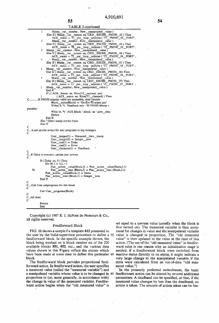
Feedback Blocks Parameters Block Operation Data passed to the user routine
Sample Source Code Feedforward Block Parameters Block Operation Data passed to the user routine Sample Source Code
Block Initialization Build-Expert and Expert Procedures
Preferred Menu Structure Standardized Data Interface Constructing the Expert System Sample Expert System
Expert Rule Structure
5
10
15
25
30
35
45
50
55
60
65
Retrieval Rules Analysis Rules Action Rules Generating the Expert Procedure
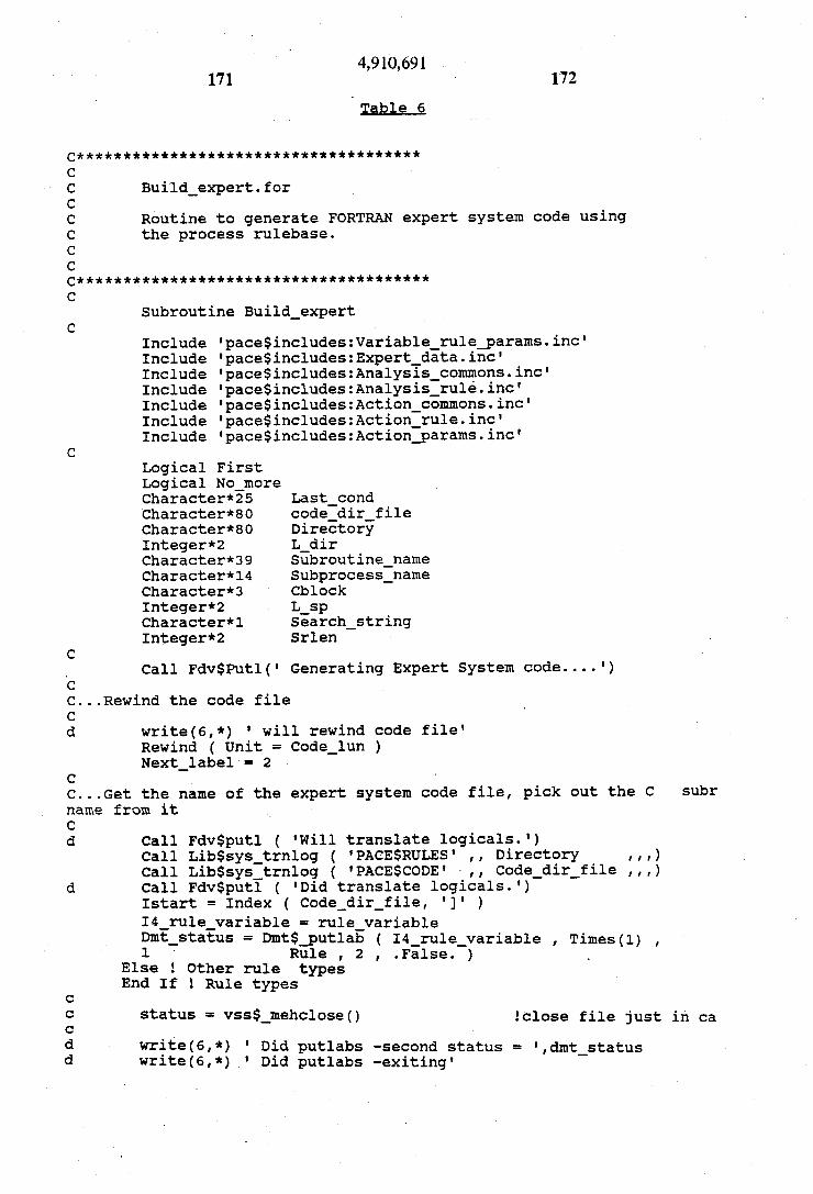
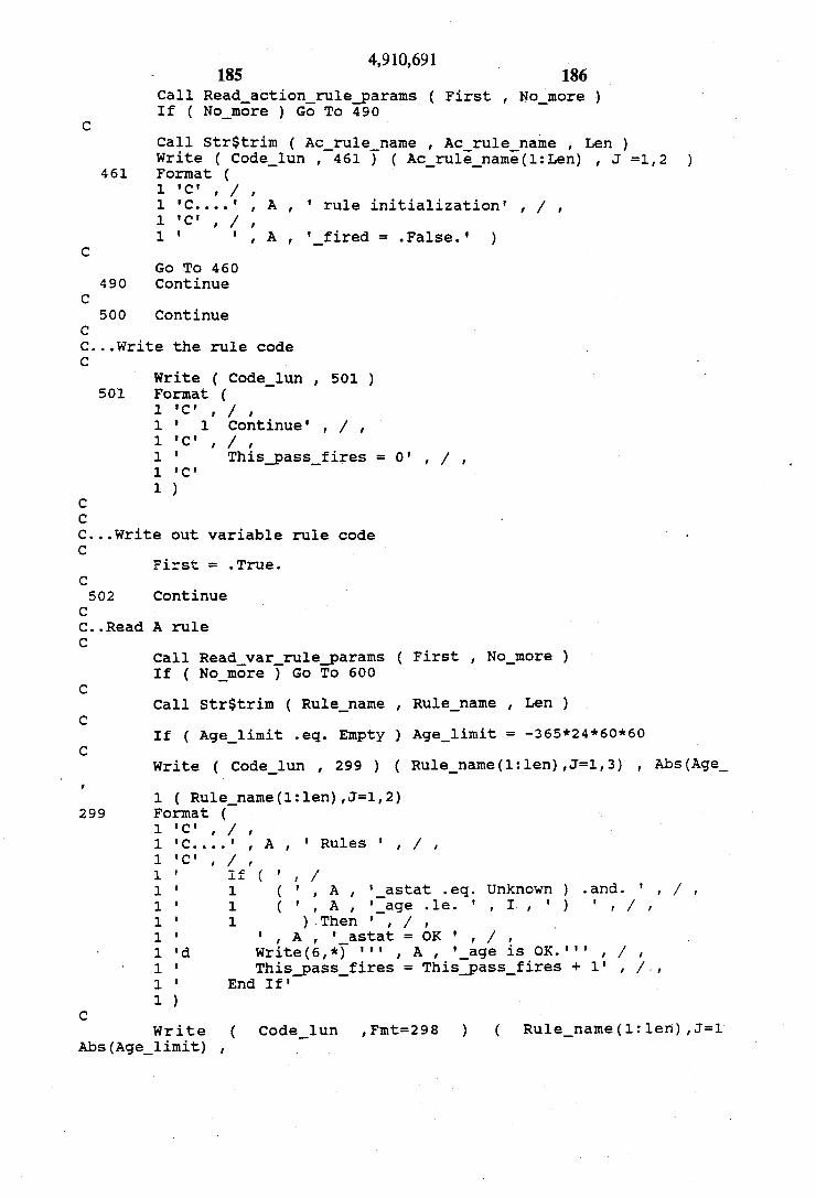
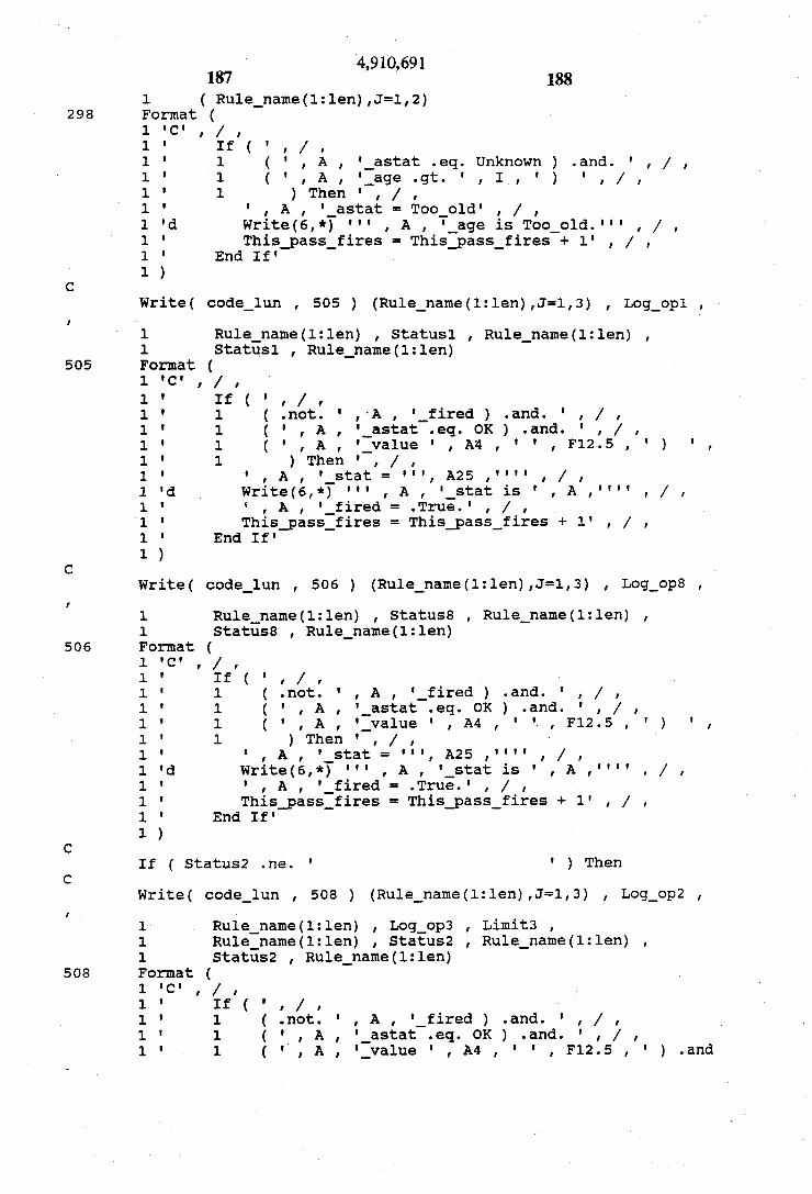
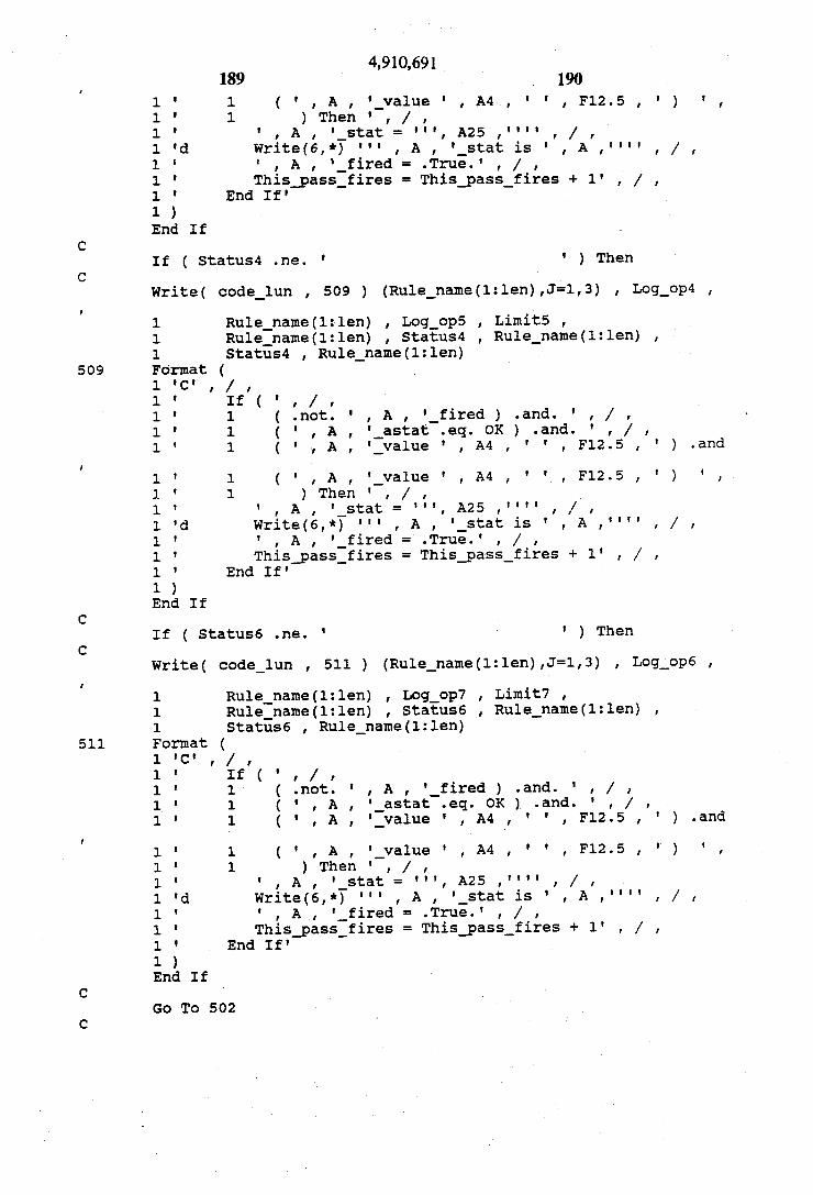
Generating Source Code Sample Source Code
Claims
A portion of the disclosure of this patent document contains material which is subject to copyright protec tion. The copyright owner has no objection to the fac simile reproduction by anyone of the patent disclosure, as it appears in the Patent and Trademark Office patent files or records, but otherwise reserves all copyright rights whatsoever.
CROSS-REFERENCE TO OTHER APPLICATIONS
The following applications of common assignee con tain some common disclosure, and are believed to have effective filing dates identical with that of the present application: EXPERT SYSTEM WITH NATURAL-LAN
GUAGE RULE UPDATING (filed Sept. 30, 1987: Ser. No. 103,050); EXPERT SYSTEM WITH THREE CLASSES OF
RULES (filed Sept. 30, 1987: Ser. No. 102,832); PROCESS CONTROL SYSTEM WITH RECON
FIGURABLE EXPERT RULES AND CONTROL MODULES (filed Sept. 30, 1987: Ser. No. 103,014); PROCESS CONTROL SYSTEM WITH ACTION
LOGGING (filed Sept. 30, 1987: Ser. No. 103,118); and PROCESS CONTROL SYSTEM WITH ON LINE RECONFIGURABLE MODULES (filed Sept. 30, 1987: Ser. No. 103,047).
BACKGROUND OF THE INVENTION
1. Field of the Invention The present invention relates to expert systems (also
known as knowledge-based systems), to process control systems, and to hybrids thereof.
2. Discussion of Related Art Various known teachings which are believed to be
related to various ones of the innovations disclosed in the present application will now be discussed. How ever, applicant specifically notes that not every idea discussed in this section is necessarily prior art. For example, the characterizations of the particular patents and publications discussed may relate them to inventive concepts in a way which is itself based on knowledge of some of the inventive concepts. Moreover, the follow ing discussion attempt to fairly present various sug gested technical alternatives (to the best of applicant's knowledge), even though the teachings of some of those technical alternatives may not be "prior art' under the patent laws of the United States or of other countries. Similarly, the Summary of the Invention section of the present application may contain some discussion of prior art teachings, interspersed with discussion of gen erally applicable innovative teachings and/or specific discussion of the best mode as presently contemplated, and applicant specifically notes that statements made in the Summary section do not necessarily delimit the various inventions claimed in the present application or in related applications.
4,910,691 3
Process Control Generally To compete in global markets, manufacturers must
continually improve the quality and cost of manufac ture of their products. They must do this in the face of changing market needs, changing raw materials costs, and reduced staffing. Automatic computer control of the manufacturing process can play an important part in this, especially in the chemical process industry. Most process plants already have the basic automatic regulat ing controls (low level controls) needed to control the plant at a given operating point. These provide the foundation for higher level supervisory controls (re ferred to here as supervisor procedures or supervisors) that seek to improve quality, reduce cost, and increase plant uptine by moving the plant to a different operat ing point. These changes can be made directly via the lower level controls, or indirectly via the plant opera tO. Although supervisory controls have been in use for
years, they have lacked a number of desirable features. To best improve quality and cost, a supervisor proce dure should:
help control the quality of the end product; reduce the cost of operating the plant; help avoid unnecessary upsets or shutdowns; work effectively with plant operators; act in concert with standard operating procedures;
and be supportable by plant operating and support peo
ple. To measure quality, a supervisor procedure should
ideally have access to measurements of the basic prop erties of the product which affect its value and useful ness to the customer. Since most product properties measurements are sampled (and are measured in a labo ratory), the supervisor should have access to a historical process database which can store these measurements as well the basic process data from the lower level control systems. Since sampled measurements and the process itself normally include some components of random variation, the supervisor should include statistical tests which can determine if a sequence of sampled measure ments is varying normally around its aim value (i.e. is "on aim'), or has shifted significantly from aim (is “off aim'). To control quality, a supervisor procedure should
have the capability to change the operating point of the process (via the lower level controls) when a measured property goes off aim. It should have the ability to act in response to new data or statistical tests, or to act at regular time intervals. It should also be able to preemp tively change the operating point when basic conditions (such as plant production rate) change. It should allow a number of independent control objectives, and new ones should be easy to add. Since the process may use any number of different low level controllers, the super visor should be able to communicate with all of them. To work effectively with plant operators, a supervi
sor procedure should be understandable. It should carry out its control actions in a way that is natural and under standable to operators. It should provide enough infor mation about its current state and its past actions for the operator to judge its performance. It should inform the operator when it acts (or chooses not to act), explaining how much action was taken, where it was taken, why it was done, and what effect it might have. Since the effect of actions taken to control quality and reduce cost
5
10
15
20
25
35
45
50
55
60
65
4. can last longer than a single shift, it should provide a record of all its actions. To act appropriately under all circumstances, to re
duce operating costs in a way consistent with quality, to help avoid unnecessary upsets and shutdowns, and to take operating procedures into account, a Supervisor should ideally include the logical decision making capa bilities of expert systems. Because decisions will nor mally focus on a specific task or area, many independent expert systems should be allowed. The expert systems should have access to the many sources of process mea surements, laboratory measurements, and control sys tem parameters. They should be able to reason symboli cally using that information, and to make their decisions take effect through communication and control actions. To work effectively, the supervisor should be able to control its expert system functions in concert with its other functions. To be supported by plant personnel, the supervisor
should be easy to use. It should allow common control actions to be set up easily, with a means of customizing less common functions. It should allow control actions to be changed easily. It should have a simple means of specifying the informative messages to be generated about it actions. Its expert systems should allow process knowledge to be entered, stored, and updated in a way that plant support people understand. It should provide a simple, appropriate knowledge representation which naturally includes data retrieval, symbolic reasoning, and effective means of implementing decisions in the plant. The knowledge structure should allow any au thorized plant expert to enter knowledge, without re stricting access to those who know computer languages or have memorized special rule structures. The present invention addresses many of these con CS
Normally supervisory control has been thought of separately from another higher level of control called optimizing control which seeks to minimize operating cost. In some cases, the requirement to minimize varia tion in product properties (i.e. to improve product qual ity) is absolutely primary, so that cost optimization only be performed as an objective secondary to quality ob jectives. In this environment, use of classical optimiza tion techniques to achieve cost optimization may not be possible. In other cases, it has been possible to integrate a balance of supervisory and optimizing control into the supervisor.
Modularity Supervisory control systems using a modular struc
ture are well known. For example, the Process Moni toring and Control-1000 (PMC-1000) control package marketed by Hewlett Packard is a modular control package which can function as a supervisory control system. PMC modules, called blocks, perform alarming and limiting, proportional/integral/derivative control, trending, driving an electrical output, running pro grams, and other functions. Each block writes one or more output values into memory. To build PMC con trol structures, the user creates as many blocks as needed and links them to other block output values. A new runnable system must then be generated. Once the System is running, parameters such as gain constants can be changed, but the linking of blocks is fixed. PMC runs on a base time cycle, and blocks can only be scheduled to execute at multiples of the base cycle time. Although PMC maintains a historical database, it cannot be used
4,910,691 5
for control, and does not effectively store intermittently sampled data. It is believed that there is no maximum number of blocks.
It is believed that some earlier discussion of the signif icance of modularity in process control software is found in Watson, "Process Control Using Modular Package Software,' IEE Conference Publications num ber 102 (1973) (which is hereby incorporated by refer ence).
Historical Process Database A database of historical process data is generally
described in Hale and Sellars, "Historical Data Record ing for Process Computers,” 77 Chem. Engg Progress 38 (1981) (which is hereby incorporated by reference).
Continuous Control Actions
In classical feedback and feedforward control, the prior art teaches that the best control results are achieved by making continuous changes to the process. In computer control, where cyclic operation forces changes to be made in discrete steps, many small, fre quent steps are conventionally preferred. While in prin ciple this gives the best possible control performance, such control actions are very difficult to visualize. In fact, it may be impossible to determine what actions have been taken by what control strategies, and how long the control strategies have been making changes. This makes it very difficult to judge whether control strategies are working properly, or even if they are working at all. This method of control also runs counter to the methods used by operators, who generally make a few significant changes and wait to see the effects.
In feedback control, the use of a deadband is a well know way of avoiding small actions caused by a noisy measurement. (That is, if the control variable falls within a specified deadband of values surrounding the goal value, the control value will not be manipulated.) This deadband, as is well known, helps to avoid instabil ity in control systems. Statistical process control also tends to reduce the number offeedback control actions. However, neither technique is sufficient to make all control actions understandable, since some actions will not be considered noisy. The use of a feedforward relation among control
variables is also well know among those skilled in the art of process control. That is, in some cases, whenever one variable changes (e.g. if a particular control vari able is manipulated for any reason), another variable will also be manipulated according to a predetermined relationship. For example, in a distillation process, it may be desirable to immediately decrease the heat input whenever the rate of feed of the crude feed stock is decreased. In feedforward control, a deadband is nor mally not used.
Control of Multiple Manipulated Variables In many process control applications, several manip
ulated variables must be jointly controlled in a single control loop (e.g. in some relation to a single measured variable). A special (and very common) case of this is seen in many situations where a single manipulated variable can normally be used, but alternate manipu lated variables should be used instead if the first-choice manipulated variable becomes constrained. When human operators optimally handle problems of this kind, their choice of which output to change will often
10
15
20
25
30
35
45
50
55
65
6 be made heuristically, based on cost, quality, response dynamics, and process stability. "Decoupling' is a conventional way of reducing
multi-input multi-output problems to sets of single-input single-output problems. In decoupling, it is usually as sumed that all of the manipulated variables should be changed. A different but related problem arises when a number
of manipulated variables ("knobs') can be changed to respond to a single measured variable. Operators often use a heuristic approach in choosing which knob (or knobs) to manipulate, and sometimes choose not to act. The heuristic approach may consider cost, quality, re sponse dynamics, and process stability. It may include alternate knobs to be used when all of the preferred knobs are constrained. Classic control methods are not well suited to this approach.
Expert Systems Generally The term "expert system' is used in the present appli
cation (in accordance with what is believed to be the general usage at present) to refer to a system which includes non-trivial amounts of knowledge about an underlying problem. Almost any control system which has been customized for a particular application might be argued to embody small amounts of relevant knowl edge in its very structure, but the term expert system is generally used only for systems which contain enough accessible information that they can usefully supple ment the knowledge of at least some (but normally not all) human users who must deal with problems of the type addressed. Expert systems at their best may serve to codify the expert knowledge of one person (a "do main expert'), so that that person's expertise can be distributed and made accessible to many less expert users who must address problems of a certain type. Some well-known successful examples include a medi cal diagnostic program (MYCIN) and a diagnostic pro gram which assists mechanics working on diesel en gines. As these examples show, one very common area of
application for expert systems has been fault diagnosis. Many other areas of application have been recognized; see generally Expert Systems (ed. R. Forsythe 1984) (which is hereby incorporated by reference); P. Har mon and D. King, Expert Systems (1985) (which is hereby incorporated by reference); and Donald Water man, A Guide to Expert Systems (1984) (which is hereby incorporated by reference).
Knowledge Input and Updating One of the very general problems in the area of expert
systems is how knowledge is to be gotten into an expert system in the first place. That is, specialists in artificial intelligence often assume that a "knowledge engineer' (that is, a person who is experienced and competent in the specialized computer languages and software com monly used for artificial intelligence applications) will interview a "domain expert' (that is, a person who actually has expert knowledge of the type of problems which the expert system is desired to be able to address) to extract his expertise and program an expert system accordingly. However, there are some very important drawbacks to this prradigm. First, competent "knowl edge engineers' are not readily available. In particular, the requirements of maintaining a real-world applica tion (such as an expert system for chemical process control, as in the preferred embodiments disclosed be
4,910,691 7
low) are such that it is dangerous to rely on a sufficient supply of "knowledge engineers' to go through the iterations necessary to not only input the knowledge base reliably, but also maintain the software base once it is created. The rapidly developing art of software engineering
has shown that one of the key requirements for a large software system is that it be maintainable. Thus, for example, the software system must be set up so that, after the technologist who first puts together an expert system is gone, it can be maintained, modified, and updated as necessary by his successors. Thus, one key problem in the area of expert systems
is the problem of maintenance and updating. Especially in more complex real-world applications, it is necessary that a large software structure, such as that required for a sophisticated expert system, be maintainable. For example, in an expert control system, control strategies may be modified, new control strategies may be intro duced, sensor and/or actuator types and/or locations may be changed, and the economic factors relevant to cost versus throughput versus purity tradeoffs may change. Normally, expert systems attempt to maintain some degree of maintainability by keeping the inference rules which the processor executes separate from the software structure for the processor itself. However, this normally tends to lead to a larger software structure which operates more slowly.
Specialists in expert systems also commonly assume that expert systems must be built in a symbolic process ing environment, e.g. in environments using LISP or PROLOG. Even for complex processes, a single large knowledge base is usually assumed. The program which processes the knowledge therefore requires complex procedures for processing the knowledge base, and these are typically coded separately from the knowl edge. This leads to large software structures which execute slowly on conventional computers. Specialized "LISP machines' are commonly recommended to speed up the inference process.
Expert System Knowledge Structures Published material regarding knowledge based sys
tems (expert systems) has proposed several classifica tions for the types of rules which are to be used. For example, U.S. Pat. No. 4,658,370 to Erman et al., which is hereby incorporated by reference, describes "a tool. for building and interpreting a knowledge base having separate portions encoding control knowledge, factual knowledge, and judgmental rules.’” (Abstract) The method described in this patent still appears to rely on the availability of a "knowledge engineer.” This patent appears to focus on the application of an expert system as a consultation driver for extracting the relevant items of knowledge from a human observer. Knowledge is separated into factual knowledge such as classes, attri butes, allowed values, etc., which describe the objects in the domain; judgmental knowledge, which describes the domain (and its objects) in the form of rules; and control knowledge describing the problem solving pro cess to be used by the inference procedure in processing the knowledge. (The control knowledge has nothing to do with control of an external process.) This knowledge structure is designed to make the task of knowledge engineering easier, and to make the knowledge system and its reasoning during a consultation easier to under stand. The knowledge base is written in a specialized
O
15
20
25
30
35
45
50
55
60
65
8 programming language. This is a very powerful struc ture, which requires a very high skill level.
Expert system development tools which are designed to make the input of knowledge easier have been devel oped. U.S. Pat. No. 4,648,044 to Hardy, et al., describes “a tool for building a knowledge system... which in cludes a knowledge base in an easily understood Eng lish-like language expressing facts, rules, and meta-facts for specifying how the rules are to be applied to solve a specific problem'. (Abstract). Although this tool is not as complex as some current expert systems tools, the knowledge must be entered in a rigidly structured for mat. The user must learn a specialized language before he can program the knowledge base. Despite some simplification in the development process, a fairly high skill level is still required.
Expert Systems for Process Control Chemical processing plants are so complex that few
people develop expertise except in limited areas of the process. Plants run around the clock, production rates on a single line are very high, and startup is usually long and costly, so improper operation can be very costly. It has also been fund that, in a complex chemical process ing plant, some operators can achieve substantially higher efficiencies than others, and it would be advanta geous if the skill level of the best operators could be made generally available. Expert systems promise sig nificant benefits in real-time analysis and control by making scarce expertise more widely available. How ever, application of expert systems in this area has not progressed as far as it has in interactive, consultative ScS.
Integration of expert system software with process control software poses special problems:
First, there is the problem of how the software struc ture for an expert system is to be combined with the software for a process control system. Several expert systems which have been suggested for process control have used an expert system as the top-level supervisor procedure for the control system.
Second, as discussed above, many process control strategies have difficulty with situations where there are multiple control parameters (inputs to the process) which could be manipulated. That is, for processes which have only one primary control parameter (as many do), the problem of what value to set for that control parameter is in significant ways a much simpler problem than the question of which one or ones of multiple control parameters should be addressed, and in which direction.
It should also be noted that the use of an expert sys tem to design a new process (or to debug a newly intro duced process) has significantly different features from the problem of optimally controlling an existing pro cess. Similarly, while expert systems have also been applied to the automatic distribution of jobs to multiple workstations through an automated materials handling system (an example of this is the DISPATCHER Fac tory Control System developed by Carnegie Group Inc.), the queuing problems presented by the allocation of different types of materials in batches to many paral lel assembly workstations making different products are quite different from the problems in continuously oper ating single line processes, particularly chemical pro CeSSS,
4,910,691 9
“RESCU'
The system known as "RESCU' resulted from a collaborative demonstration project between British government and industry. See, e.g., Shaw, "RESCU 5 online real-time artificial intelligence,” 4 Computer Aided Engineering J. 29 (1987) (which is hereby incor porated by reference); and the Digest of the IEE Collo quium on "Real-Time Expert Systems in Process Con trol, held 29 Nov. 1985 at Salford, U.K. (which is hereby incorporated by reference). From available in formation, it appears that this is a real-time expert sys tem which was developed to provide advice on quality control in an detergent plant. The system searches for a hypothesis about the plant which is supported by pro cess data, and uses it as the basis for advice. This system also uses a single knowledge base for the entire plant and thus requires complex inference control methods.
“Falcon'
"Falcon' is a fault diagnosis system for a chemical reactor, which monitors up to 30 process measurements and seeks to identify a set of up to 25 failures in the process. This was developed as a demonstration project between DuPont, the Foxboro Company, and the Uni versity of Delaware, and is described, for example, in D. Rowan, "Using an Expert System for Fault Diagno sis,' in the February 1987 issue of Control Engineering, which is hereby incorporated by reference. See also "Troubleshooting Comes On Line in the CPI' in the Oct. 13, 1986, issue of Chemical Engineering at page 14, which is hereby incorporated by reference. This system required several man years of development, and be cause it is programmed in LISP, it has proven difficult to maintain the knowledge base through process changes.
“ONSPEC Superintendent' The “ONSPEC Superintendent' (TM), marketed by
Heuristics Inc., is a real-time expert systems package which monitors data from the ONSPEC (TM) control system. See Manoff, "On-Line Process Simulation Techniques in Industrial Control including Parameter Identification and Estimation Techniques,” in Proceed ings of the Eleventh Annual Advanced Control Conference (1985) (which is hereby incorporated by reference); and Manoff, "Control Software Comes to Personal Com puters,' at page 66 of the March 1984 issue of Control Engineering (which is hereby incorporated by refer ence). The "Superintendent' monitors for conformance with safety and control procedures and documents ex ceptions. It can also notify operators, generate reports, and cause control outputs.
“PICON
The PICON (TM) system, which was marketed by Lisp Machines, Inc. (LMI), was apparently primarily intended for real-time analysis of upset or emergency conditions in chemical processes. It can monitor up to 20,000 input process measurements or alarms from a distributed control system. It uses a single knowledge base (e.g. containing thousands of rules) for an entire process. To handle such a large number of rules, it runs on a LISP computer and includes complex inference control methods. PICON must be customized by a LISP programmer before the knowledge base can be entered. The domain expert then enters knowledge through a combination of graphics icons and Lisp-like
10
15
20
25
35
45
50
55
60
65
10 rule constructions. See, for example, L. Hawkinson et al., “A Real-Time Expert System for Process Control,' in Artificial Intelligence Applications in Chemistry (Amer ican Chemical Society 1986), which is hereby incorpo rated by reference, and the R. Moore et al. article in the May 1985 issue of InTech at page 55, which is hereby incorporated by reference.
Self-tuning Controllers Another development which should be distinguished
is work related to so-called "self-tuning controllers." Self-tuning single- and multiple-loop controllers contain real-time expert systems which analyze the perfor mance of the controller (See “Process Controllers Don Expert Guises', in Chemical Engg, June 24, 1985). These expert systems adjust the tuning parameters of the controller. They affect only low-level parts of the system, and use a fixed rule base embedded in a micro processor.
SUMMARY OF THE INVENTION.
. In this section various ones of the innovative teach ings presented in the present application will now be discussed, and some of their respective advantages de scribed. Of course, not all of the discussions in this section define necessary features of the invention (or inventions), for at least the following reasons: (1) vari ous parts of the following discussion will relate to some (but not all) classes of novel embodiments disclosed; (2) various parts of the following discussion will relate to innovative teachings disclosed but not claimed in this specific application as filed; (3) various parts of the following discussion will relate specifically to the “best mode contemplated by the inventor of carrying out his invention' (as expressly required by the patent laws of the United States), and will therefore discuss features which are particularly related to this subclass of em bodiments, and are not necessary parts of the claimed invention; and (4) the following discussion is generally quite heuristic, and therefore focusses on particular points without explicitly distinguishing between the features and advantages of particular subclasses of em bodiments and those inherent in the invention generally.
Various novel embodiments described in the present application provide significant and independent innova tions in several areas, including:
systems and methods for translating a domain expert's knowledge into an expert system without using a knowledge engineer;
software structures and methods for operating a so phisticated control system while also exploiting expert system capabilities;
generally applicable methods for controlling a con tinuous process; and
innovations, applicable to expert systems generally, which help provide highly maintainable and user friendly experts.
Various classes of embodiments described herein provide a process control system, wherein a process which operates substantially continuously is controlled by a system which includes (in addition to a process control system which is closely coupled to the underly ing process and which operates fairly close to real time, i.e. which has a maximum response time less than the minimum response time which would normally be nec essary to stably control the underlying process) at least some of the following features:
4,910,691 11
(1) A supervisor procedure, which has a modular structure, and retrieves process measurements from the process control system (or other process data collection systems), passes control parameters to the process con trol system, and communicates with people. Preferably, the supervisor includes the capability for statistical pro cess control. The supervisor preferably runs on a com puter system separate from the process control system.
(2) The supervisor procedure can preferably call on one or more expert system procedures as subroutines. This is particularly useful in control applications where there are multiple possible manipulated variables, since the expert system(s) can specify which manipulated variable (or variables) is to be adjusted to achieve the end result change desired, and the supervisor system can then address simpler one-dimensional control prob lens.
(3) Preferably, at least some users can call on a build supervisor procedure which permits them to define or redefine modules of the supervisor procedure by editing highly constrained templates. The templates use a stan dardized data interface (as seen by the user), which facilitates the use in control actions of data from a wide variety of systems. The templates in the available tem plate set preferably contains highly constrained por tions (which are optimized for the most common func tions), and pointers to functions which can be custom ized by the user.
(4) Preferably, the build-supervisor user can also call on a build-user program procedure, which allows fully customized control functions to be programmed by sophisticated users. The build-user program procedure can also be used to create customized message genera tion functions. These can be used to generate messages describing the actions of the supervisor, and also to call other sub-procedures, such as the expert procedures.
(5) Preferably at least some users are also permitted to call on a build-expert procedure which can be used to construct an expert system. Knowledge is specified by user input to a set of highly constrained, substantially natural language templates. The templates use a stan dardized data interface (as seen by the user), which facilitates the use in the expert system of data from a wide variety of systems. The completed templates can then be compiled to produce a runnable expert system. Preferably, the user can also retrieve, examine, and modify the input from previously specified templates. Thus, an expert system can be modified by recalling the templates which specified the current expert system, modifying them, and recompiling to generate a new runnable expert.
(6) A historical process database advantageously standardizes the access to current and historical process data by the supervisor and expert procedures. This is particularly useful for collecting the results of labora tory characterizations over time of the underlying pro CSS.
Control of Continuous Processes
The goals in management of a substantially continu ous process include the following:
(1) Maximizing quality: In the chemical process in dustry, it is important to reduce variation in measured properties of the product, and to control the average measured properties at specified aim values.
(2) Minimization of cost of manufacture: The process must be operated in a way hat efficiently uses energy and feedstocks without compromising quality objec
10
5
25
30
35
45
50
55
60
65
12 tives. Upsets and inadvertent process shutdowns, which adversely affect quality and production rate, and reduce the total utility (fractional uptime) of the plant, are all costly and must be avoided.
Control of Multiple Manipulated Variables As noted above, in many process control applica
tions, several manipulated variables must be jointly controlled in a single control loop (e.g. in some relation to a single measured variable). A special (and very com mon) case of this is seen in many situations where a single manipulated variable can normally be used, but alternate manipulated variables should be used instead if the first-choice manipulated variable becomes con strained. When human operators optimally handle prob lems of this kind, their choice of which output to change will often be made heuristically, based on cost, quality, response dynamics, and process stability. One novel approach to this problem (which is used in
several of the preferred embodiments below) is to de compose the multiple-variable problem into a set of single-variable problems. An expert procedure is used to decide which control parameter(s) to adjust, and one or more from a set of single-input single-output proce dures are used to make the adjustment(s). Not only does this facilitate quality, cost, and plant operability objec tives, but it results in control strategies which act prop erly over a much wider range of conditions. Correct actions are taken, where conventional control methods would make no action or wrong actions. This improves the usefulness of the control strategy to the operator, and leads to higher use of the controls. The various novel ideas described below are particu
larly advantageous in such multiple control parameter problems. In the presently preferred embodiment dis cussed below, a dimethyl terephthalate process (DMT) process is presented as an actual example to show the advantages achieved by the various novel ideas dis closed in this context.
Discrete Control Actions
As mentioned above, control systems that continu ously change manipulated parameters are very difficult to monitor. Since operators depend on the supervisor procedure to maintain important product properties and process operating conditions, it is important that they be able to understand and judge supervisor performance. By restricting supervisor changes to a reasonably small number of significant discrete actions, supervisor per formance becomes much more understandable. One novel teaching stated in the present application is
an integrated system for process control in which a process supervisor procedure (which is preferably the top level procedure) defines parameters for one or more control systems (or control procedures). The supervisor procedure changes control parameters only in discrete actions, and the thresholds for the decision to act are preferably made large enough (for each control parame ter) that every action must be a significant change. A related novel teaching herein is that every control
action taken by the supervisor should be reported out to plant personnel in a substantially natural language mes Sage. Preferably, instances where action would be desir able but is not possible (because of constraints or other unusual circumstances) should also be reported. Prefer ably, a cumulative record of the messages is kept, and is available for review by operators and plant support people. Preferably, the message should report the time,
4,910,691 13
amount, location, and reason for each action. Other relevant information, such as the time stamp of relevant sampled data, and the nature of statistical deviations from aim should preferably be included as well. Since every action is significant, and the number of actions is reduced, the cumulative record provides a meaningful record of supervisor performance. This is particularly advantageous for systems where
some of the relevant time constants are so slow that dynamic process responses last several hours (or longer). A new operator coming on duty at a shift change can use the cumulative record to judge what effects to expect from supervisor actions on the previ ous shift. The use of a deadband in feedforward action is one
novel means that is advantageously used to discretize supervisor actions. Feedforward action is taken only when the measured value changes by more than the deadband from its value at the last action. This gener ates a series of discrete changes in the manipulated variable, which can be effectively logged and evaluated by operators.
Statistical filtering of discretely measured values also serves to reduce control actions to a few significant changes. Statistical tests, as is well known, distinguish normal variation around the average from significant deviations from the average. In most cases, a number of measurements will be needed to indicate a deviation. By only acting on statistical deviations, relatively few, but significant, actions will result.
Expert Systems for Process Control A general problem with expert systems is how the
expert system software is to be integrated with process control software. Several expert systems which have been suggested for process control have used an expert system as the top-level supervisor procedure for the control system. However, several of the novel embodi ments disclosed herein achieve substantial advantages by departing from this conventional structure. For one thing, if the expert system is the top level procedure, then it becomes more difficult to accommodate more than one expert in the system (or, to put this another way, the potential modularity of the expert system can not be fully exploited). Thus, one significant advantage of several of the novel embodiments disclosed here is that use of more than one expert system within a single integrated system becomes much more advantageous.
Types of Process Control Systems It should also be noted that the use of an expert sys
tem to design a new process (or to debug a newly intro duced process) has significantly different features from the problem of optimally controlling an existing pro cess. While various ones of the novel ideas disclosed herein may have significant applications to such prob lems as well, the presently preferred embodiment is especially directed to the problem of optimally control ling an existing operating process, and the various novel ideas disclosed herein have particular advantages in this context. A significant realization underlying several of the
innovations disclosed in the present application is that the structure of expert systems for process control ap plications can advantageously be significantly different from that of other expert system problems (such as consultative expert systems problems, in which a human is queried for information). The Hardy et al. and Erman
10
15
20
25
30
35
45
50
55
60
65
14 et al. patents illustrate this difference. Consultaive ex pert systems seek to substantiate one of a number of possible causes by interactively querying the user about the symptoms. Such systems must use complex knowl edge representations and inference methods to minimize the number of user queries by carefully selecting the information they solicit. Moreover, since the user is not an expert, the system should be able to explain why it is requesting information.
In contrast, the real-time process problem is much simpler. The information needed by the expert is typi cally in the form of process measurements, which can be rapidly retrieved from process control and data sys tems without human intervention. There is much less need to minimize the requests for information. In fact, it may be faster to retrieve all the data that could be rele vant to the problem than to determine what data is relevant. Moreover, since the experts will run automati cally, there is no need to explain the reasoning during the inference process. As long as the rulebase is not too large, the process control expert can operate effectively using a simple "forward chaining' (or data driven) inference method. There is no need for the complex "backward chaining' procedures used in the consulta tive systems. Moreover, if a number of modular expert subprocedures are used within a single process, each expert tends to be smaller, and is more likely to work effectively in forward chaining mode. The presently preferred embodiment is especially directed to process control and monitoring, and the novel ideas disclosed herein have particular advantages in this context. How ever, various ones of the novel ideas may have signifi cant applications to other problems as well.
It is believed to be a significant innovation to use expert system techniques to point to the direction of action in a multi-parameter control problem, as dis cussed above. One advantage is that the use of the ex pert permits more cases to be handled; for example, when one control parameter is up against its limits, the expert system can specify another parameter to be changed. The expert can also be especially advanta geous in preventing a wrong action from being taken: in some types of processes it is conceivable that erroneous control strategies could potentially cause property dam age or injuries, and the natural language inference rules of the expert (possibly combined with a more quantita tive optimization scheme) can usefully ensure that this cannot happen. Thus, one advantage of various of the process control expert system embodiments disclosed in the present application is that they facilitate reliable implementation of a control strategy which (primarily) prevents a clearly wrong action from being taken, and (secondarily) permits minimizing costs.
In particular, it is especially advantageous to use a knowledge based (functional) structure where the rules are constrained to be of the three types described in the context of a process control application. The retrieval rules permit the predominantly quantitative sensor data (and other input data) to be translated into a format which is suitable for expert system application, and the control rules provide a translation back from expert system reasoning into an output which matches the . constraints of the control problem. The present invention is particularly advantageous in
controlling processes which are substantially continu ous, as distinguished from job shop processes. That is, while some computer-integrated manufacturing systems focus primarily on issues of queuing, throughput, statis
4,910,691 15
tical sampling of workpieces for inspection, etc., sub stantially continuous processes (such as bulk chemical synthesis and/or refining processes) typically demand more attention to issues of controlling continuous flows.
Expert Systems Generally The present application contains many teachings
which solve specific problems and offer corresponding advantages in the sub-class of expert systems used for process control, or even the sub-sub-class of expert systems used for control of substantially continuous processes. However, the present application also dis closes many novel features which could be adopted into many other types of expert systems, and/or into many other types of control applications, while still retaining many (if not all) of the advantages obtained in the con text of the presently contemplated best mode.
Similarly, while the present application describes numerous novel features which are particularly applica ble to rule-based forward-chaining expert systems, some of the innovations described herein are believed to be very broadly novel, and could be adapted for use with other types of expert systems too.
Natural-Language Rule Statements One of the innovative teachings in the present appli
cation provides an expert system tool in which knowl edge is entered into the knowledge base through a lim ited set of pre-defined, highly constrained, natural-lan guage knowledge structures which are presented as templates. In typical previous expert systems, knowl edge is coded in the strict syntactical format of a rule or computer language, which allows great flexibility in knowledge representation. The person entering the knowledge (hereafter referred to as the developer) must learn the syntax, must choose an appropriate knowledge representations, and must formulate syntactically cor rect input.
In contrast, by restricting the developer to con strained, pre-defined structures, the need to learn rule or language syntax and structure is eliminated. More over, if the number of such pre-defined knowledge structures is small enough, the total knowledge repre sentation in the expert system can be easily understood. Thus, a knowledge engineer is not needed. The domain expert can enter the knowledge to build an expert sys tem directly. The developer's input can then be trans lated automatically into an operational expert system. The developer need not be concerned with or aware of the specific language or system used to implement the expert. Another innovative teaching is that the knowledge
entered into the pre-defined natural-language structures is stored in substantially natural-language form. This permits the knowledge to be revised at any time in the form in which it was originally entered: the developer simply recalls the stored template information, modifies it and stores the modified knowledge. This is also simple enough to be done by the domain expert. The modified knowledge can then be automatically translated into a modified operational expert. Another significant advantage of several of the dis
closed novel embodiments for creating an expert system is that the expert can be significantly more compact and faster in execution. This is achieved by integrating the expert system's rules with the code which performs the inference function. This allows many independent runn able expert systems to be created. Moreover, the ease
O
15
25
30
35
45
50
55
60
65
16 and simplicity of knowledge updating can still be pre served by maintaining the natural language form of the knowledge. The knowledge base can easily be reviewed and modified without hindrance from the specific infer ence method used in the runnable system. Another novel feature of several of the disclosed
embodiments is the use of a standardized data interface (as seen by the user) in the knowledge templates, which facilitates the use in the knowledge base of data from a wide variety of systems. Expert systems are allowed to require data from process or laboratory measurements (both current and historical), or data collected from other sources (such as on-line analyzers), or data and parameters from the process control systems. A stan dard interface to all such data sources facilitates use of the data in expert systems, since domain experts usually lack the programming expertise that would otherwise be needed to access these data sources.
Expert System Rule Types As mentioned above, previous expert systems tools
normally use a rule or computer language which allows great flexibility in knowledge representation. One inno vative teaching in the present application is the restric tion of the knowledge structure within an expert system to rules of three highly constrained types. The three rule types are: (1) retrieval rules, which each assign one of several descriptors to a name in accordance with the values of numeric inputs; (2) analysis rules, which each can assign a descriptor to a name in accordance with tee descriptor/name assignments made by other rules; and (3) action rules, which either execute or don't execute a command in accordance with the descriptor/name as signments made by other rules.
Preferably only the retrieval rules include numeric operations. Preferably only the action rules can enable execution of an external command (i.e. of a command which does not merely affect the operation of the expert procedure). Preferably each of the action rules requires only a logical test for the assignment of a descriptor to a name. Preferably none of the action rules can assign a descriptor to a name. While this organization of an expert system's struc
ture is especially advantageous in the context of a pro cess control expert system, it can also be applied to other types of expert systems. In a process control sys tem, the relevant inputs will normally be process data, laboratory data, or control system parameters. The relevant outputs will normally be executable proce dures which affect the operation of control or supervi sor-systems, or communicate with operators or domain experts. This teaching could also be applied to expert systems generally, in which other input and output functions are more important.
For example, in consultative use, retrieval rules need not be confined to numeric inputs, but could accept the natural language descriptor/name assignments as input from the user. To better control the requests for input, such consultative retrieval rules could advantageously execute contingent upon a test for the previous assign ment of a descriptor to a name.
In general, this structuring of the inference rules pro vides for a more understandable expert. The retrieval rules provide access to process and control system data, and translate from quantitative input data into a natural language form. The emulation of natural-language rea soning is concentrated as much as possible in the analy sis rules, which capture knowledge in a form which
4,910,691 17
might be used to communicate between domain experts. The action rules translate from the natural language inference process back to output procedures which are meaningful in the computer and control system being used.
Modular Organization The organization preferably used for process control
has substantial advantages. The top level procedure is a modular process supervisory controller. The supervisor modules allow flexible specification of timing and coor dination with other modules. Modules carry out com monly used control functions, using data specified through a standard data interface, as well as calling user customized functions. User customized functions might generate messages, perform unusual control actions, or call expert system procedures. Using the build-supervi sor procedure, users can define or redefine modules by editing highly constrained templates which include a standard data interface specification. The standardized data interface (as seen by the user) facilitates communi cations with an extremely wide variety of systems. Dy namic revision is achieved by storing the user input to the constrained templates as data in a storage area ac cessible to both the supervisor and build-supervisor procedures. The running supervisor examines the stored data to determine which functions have been specified for that module, and what data sources have been specified through the standard data interface. The supervisor then calls an appropriate modular function and passes the user-specified data. This organization is especially advantageous in pro
viding parallelism and branching in control strategies. That is, the modular organization of the presently pre ferred embodiment permits at least the following capa bilities:
(a) control strategies for more than one independent control application can be defined and updated;
(b) control strategies for more than one lower level process control system can be defined and updated;
(c) alternative control strategies can be defined an stored, so that an expert system (or other software or ser command) can switch or select between control strate gies merely by selecting or "de-selecting' modules;
(d) timing and coordination of module functions is facilitated;
(e) multiple independent expert system procedures can be utilized within a single supervisor;
(f) more than one user can define control strategies by accessing different modules, simultaneously if desired. Another innovative teaching herein is that each su
pervisor module (or, less preferably, less than all of the module types) should preferably contain a pointer to optional user-customized functions. These functions can be used to generate informative messages about module actions, or a Sophisticated user can implement unusual or non-standard control functions, or other customiza tion utilities (such as the build-expert procedure in the presently preferred embodiment) can be used to gener ate functions accessed in this manner. This structure is "modular' in the sense that users can
call up and modify the various blocks separately; but, as will be discussed below, the command procedures which perform the standardized block functions are not necessarily separate within the source code. That is, modularity is advantageously achieved by storing the template-constrained user inputs to each block as data; when the user wishes to modify the block, the data is
10
15
20
25
30
35
45
50
55
65
18 translated back into corresponding fields in the tem plate.
Preferably, one of the modular functions in the super visor is statistical filtering. This is particularly useful in that statistical filtering can be introduced wherever it is advantageous, without requiring extensive custon pro gramming by the users. As described above, statistical filtering is advantageous both for avoiding overreaction to insignificant changes, and also for aiding the under standing by plant operators by reducing the number of actions. One of the novel teachings contained in the present
application is that the use of statistical filtering helps to minimize the number of control parameter adjustments performed by the expert system, which in turn is very advantageous (as discussed below) in providing an un derstandable log of control actions taken.
Sequencing Modular Blocks One innovative teaching herein is a system for pro
cess control having a modular supervisor procedure which includes novel module timing and sequencing methods. Users can preferably specify modules by edit ing highly constrained templates, which include several specifiers for methods to be used in controlling and coordinating module execution. Preferably the module timing options include: (1) execute module function at fixed time intervals; (2) execute module function when new data becomes available for a specified data source; (3) execute. module function whenever another module executes; (4) execute module function only on program matic request; and combinations of these. Preferably a standardized data interface is used to specify the data source for the second of these options.
Integration of Expert Procedures The integration of expert systems into process con
trol has been a challenging problem. Most previous attempts to use expert systems in process control have used LISP based expert systems running on a dedicate machine, often a symbolic processing machine. Usually only one expert system with a single large knowledge base is created for a process. Since the knowledge base could contain many rules, a complex knowledge repre sentation and inference process are needed to make inferences fast enough for real-time use. The expert system typically runs independently, scheduling its own activities, and thus is effectively the "top level” proce dure. Using a top level expert makes it more difficult to accommodate more than one expert system. (Another way to regard this area of advantage is to note that, without the inventions contained in the present applica tion, the potential modularity of the expert system can not be fully exploited.)
Several of the novel embodiments described herein achieve substantial advantages by using more than one expert system subprocedure within a single integrated system. Since expert decisions will normally focus on a specific task or area, the modularity of the problems can be exploited in the structure of the expert system. Also, if the experts run under control of the supervisor, it is much easier to coordinate the decisions of the expert systems with the control actions of the supervisor. Since many important uses of expert systems will affect con trol actions, this is an important factor. Another advantage of a modular structure, where
expert systems are included as independent procedures called by the supervisor, is that the overall process
19 control system is more reliable. A badly or incom pletely functioning expert system within an overall supervisor system will affect only the functions it specif ically interacts with. However, the failure of a top level expert system, which controls timing and execution of control functions, could disable all supervisor functions. The modular structure also has significant advantages in maintenance and debugging. Thus, the organization preferably used for process
control has substantial advantages. The top level proce dure is a cycling procedure which functions as a process control supervisor. The supervisor process can call on one or more expert system procedures, and the user can call on a build-expert procedure which can reconfigure one of the expert systems already present, or create a new expert system. The supervisor procedure can pref erably also call on a historical data base. The modular organization described is especially
advantageous, as discussed above, in providing parallel ism and branching in control strategies. This is espe cially advantageous in process control situations, since the appropriate strategies for different circumstances can be fully pre-defined by the user, and he can rapidly switch between pre-defined strategies as the need arises.
Historical Process Database
The use of a historical database of process data in combination with a process supervisor procedure and /or expert system procedure is particularly advanta geous. In the presently preferred embodiment, a histori cal database is used which can provide a time-stamp with each piece of output data, to clearly indicate prov enance, and can retrieve the stored data (for a given parameter) which bears the time-stamp closest to a given time. The historical database can preferably main tain a record of continuously measured process data (such as temperature, pressure, flow rate), as well as discretely sampled, time-delayed measurements, such as laboratory measurements. The database greatly facili tates the use of laboratory (or other sampled type) mea surements. Because of the time delay in making labora tory measurements, the value of the measurement when it becomes available in the database will correspond to the continuously measured data for the instant at which the measurement sample was actually taken, which might be several hours in the past. The historical data base allows time delayed measurements and their corre sponding continuous measurements to be used together. This is advantageous for balancing component material flows in the process. In the presently preferred embodi ment, the historical process database may be thought of as providing a way to "buffer' timestamped data and provide a standardized data interface, but it also permits other functions to be served. The historical database also advantageously provides
a basis for statistical tests. Some statistical tests will require a number of past measurements, which can be retrieved from the database. The database also advanta geously allows the calculation of time average values of measurements. This can be useful in dampening noisy signals for use in a control action. In general, the data base advantageously serves to buffer data input from a number of sources, standardizing access from the super visor and expert procedures. One of the innovative teaching in the present applica
tion is an integrated system for process control in which a process supervisor procedure (which is preferably the top-level procedure) is configured as a modular soft
4,910,691
5
10
5
20
25
35
40
45
50
55
60
65
20 ware structure, with modules which can be revised by a user at any time, without significantly interrupting the operation of the process supervisor. The supervisor can define control parameters for many process control procedures, and can retrieve data from many sources (preferably including a historical database of process data, which can provide time-stamped data). The super visor can also call on various expert subprocedures. Preferably the expert subprocedures can also be modi fied by an authorized user at any time, by calling up and editing a set of natural-language rule templates which correspond to the rules being executed by the expert subprocedure. One of the innovative teachings in the present appli
cation is an integrated system for process control in which the user can customize the process supervisor procedure with reference to a standardized data inter face. The data values to be used by the supervisor are specified in the standard interface by two identifiers. The first identifies which (software system and type of value is desired. The value of a setpoint in a particular distributed control system, the value of a sensor mea surement in a particular process monitoring system, the value of a constraint from a process control or supervi sor system, and time averages of sensor measurements from a particular historical database are examples of this. The second identifier specifies which one of that type of value is desired, for example the loop number in the distributed control system.
Data values specified through the standard interface may be used as measured values, manipulated values, or as switch stats values indicating an on/off status. Prefer ably the interface allows the user to specify data in any of the relevant process control and data collection sys tems used for the process, or for related processes. Pref. erably, the interface also allows specification of data (both current and historical) in a historical process data base. Since multiple control systems (or even multiple historical databases) may be relevant to the process, the standard interface greatly facilitates the use of relevant data from a wide variety of sources.
BRIEF DESCRIPTION OF THE DRAWING
The present invention will be described with refer ence to the accompanying drawings, wherein:
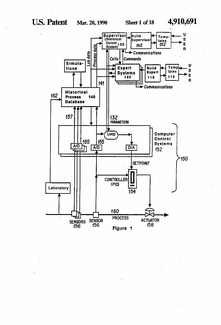
FIG. 1 schematically shows the structure of hard ware and procedures preferably used to embody the novel process control system with expert system capa bilities provided by various of the innovative features contained in the present application.
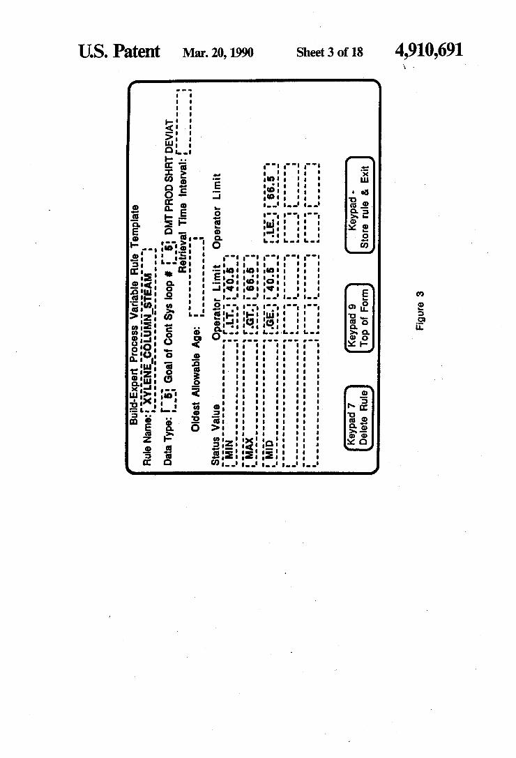
FIG. 2 is a schematic representation of the flow of information in the expert system structure preferably used. FIG. 3 shows the template used for a retrieval rule in
the presently referred embodiment, together with a sample of a retrieval rule which has been entered into the template.
FIG. 4 shows an example of a different kind of re trieval rule, known as a calculation rule. FIG. 5 shows an example of an analysis rule 220. FIG. 6 shows the presently preferred embodiment of
the template for action rules, and an example of one action rule which has been stated in tis format. FIG. 7 shows an example of a chemical synthesis
processing layout in which the method taught by the present invention has been successfully demonstrated. FIG. 8 schematically shows the structure preferably
4,910,691 21
used for the supervisor procedure 130 and the build supervisor procedure 810. FIG. 9 shows a menu which, in the presently pre
ferred embodiment, is presented to the user by the build-supervisor procedure 810 to select a template to provide user inputs to define or modify a block within the supervisor procedure. FIGS. 10–13 show specific templates which, in the
presently preferred embodiment, are presented to the user by the build-supervisor procedure to provide input to define or modify a feedback, feedforward, statistical filtering, or program block, respectively.
FIG. 14 shows a block-editing utility menu presented to the user, in the presently preferred embodiment, by the build-supervisor procedure. FIG. 15 shows a flow chart for the base cycle proce
dure used in the supervisor procedure in the presently preferred embodiment. FIG. 16 shows a menu which, in the presently pre
ferred embodiment, is the top-level menu presented to the user by the build-supervisor procedure, and FIG. 17 shows a menu which is the top-level menu within the build-expert procedure.
FIG. 18 is another schematic representation of the interrelations among the various procedures which permit user customization of functionality.
DESCRIPTION OF THE PREFERRED EMBODIMENTS
General Organization of Hardware and Procedures FIG. 1 schematically shows the structure of hard
ware and procedures preferably used to embody the novel process control system (with expert system capa bilities) provided by various of the innovative features contained in the present application. An underlying process (for example a chemical process) is very sche matically represented as a single pipe 160, on which sensors 156 an one actuator 158 are explicitly shown. Of course, real world examples are substantially more com plex; FIG. 7 shows the chemical process flow of a sam ple system in which the presently preferred embodi ment has been successfully demonstrated. The various actuators 158 are controlled, in accordance with feed back signals received from various sensors 156, by one or more controllers 154.
In the presently preferred embodiment, the controller 154 is configured as a pneumatic proportional, integral, derivative (PID) controller. However, a wide variety of other controller technologies and configurations could be used. Pneumatic controllers are used in this example because they are common in the chemical process in dustry, and match well with the feedback requirements of chemical process control. Alternatively, an all-elec tronic distributed control system could be used instead. Moreover, the controller functionality could be differ ent, e.g. a proportional/integral controller or a propor tional controller could be used instead. In the presently preferred embodiment, the PID controller 154 is di rectly controlled by a computer control system 52. (This system 152 is referred to, in the various examples of user menus shown, as "PCS’ (process control sys tem.) The computer controller system 152 and the PID controller 154 may be regarded together as a single first level controller 150, and could easily be configured in that fashion (as with a distributed digital control sys tem) to implement the present invention. The control system 150 receives at least some of its
parameters 132 (e.g. setpoints or feedforward ratios)
O
15
20
25.
30
35
40
45
50
55
60
65
22 from a supervisor procedure 130, which is preferably a higher level of control software. (In many of the sample user menus and forms shown, the supervisor procedure 130 is referred to briefly as “ACS.") The supervisor not only receives inputs 157 indirectly (or directly) from various sensors 156, it also receives lab measurement data 162, and also can issue calls to and receive inputs from the expert system 120, as will be described below.
In the presently preferred embodiment, the supervi sor and build-supervisor procedures run on a minicom puter (e.g. a VAX 11/785), while the computer control system 152 is a PDP-11. The supervisor 130 is preferably also connected to a
historical process database 140, which directly or indi rectly receives the inputs from the sensors 157 and the off-line lab measurements 162. Thus, when the supervi sor needs to access a value 157 or 162, it is not necessary for it to call on a physical device or read a real-time signal. It can simply call a stored value (together with a time stamp) from the database 140. However, many of the advantages of the present invention could also be obtained without using the historical process data base 140.
In addition, the supervisor 130 preferably also em bodies a statistical control system. Statistical control systems, as are well known in the art of chemical pro cesses, are advantageous when the process characteris tics and measurement characteristics are subject to sig nificant random variation, as they normally are in the chemical process industry. Statistical filtering tests are preferably performed to filter out statistically normal variation, and ascertain whether a process has signifi cantly deviated from its current goal or average. (Alter natively, the statistical filtering functions could be per formed elsewhere in software, e.g. in the database soft ware.) The supervisor procedure 130 is preferably run as a
cycling process, and can call multiple expert systems 120 when indicated. (In many of the sample user menus and forms shown, the expert and build-expert proce dures are referred to briefly as "PACE.') A sample realistic process context (in which numer
ous innovative features have been successfully demon strated) will first be described. The operation of the historical process database will next be described, since that provides a standardized data interface to which many of the other functions connect. Next, the func tioning of the build-supervisor procedure will be de scribed in detail, since that provides many details of how the supervisor is configured in the presently pre ferred embodiment, and after that the organization of the supervisor procedure itself will be discussed in greater detail. In later sections, the structure of the expert systems preferably used will be described in detail, and the operation of the build-expert procedure which constructs the expert systems will also be de scribed in detail.
Sample Process Context FIG. 7 schematically shows a sample embodiment of
a chemical process incorporating several novel features described in the present application. The system shown is one in which various novel aspects set forth in the present application have been advantageously demon strated.
It should be understood that the present invention provides a tool of very broad applicability, which can
4,910,691 23
be used in many processes very different from that of FIG. 7. Thus, for example, various of the claims herein may refer to sensors which sense "conditions' in a pro cess, or to actuators which change "conditions' in a process, without reference to whether one sensor or many sensors is used, whether one or several parame ters is sensed by respective ones of the sensors, whether the actuators are valves, motors, or other kinds of de vices, etc. FIG. 7 shows part of the distillation train of a process
in which paraxylene is air oxidized to make terephthal lic acid, which is then esterified with methanol and refined to dimethyl terephthallate (DMT). DMT is sold as a bulk product, and commonly used as a polyester precursor. The esterification process will produce a significant fraction of the impurity methyl formyl ben zoate (MFB). One of the key objectives in a DMT syn thesis process is controlling the compositional fraction of MFB, since it affects the properties of products made from DMT. The refining train shown in FIG. 7 will
10
5
20 reduce the average MFB fraction to a fairly constant level which is (in this example) about 22 ppm (by weight). The crude feed 702 will typically have a composition
which is (by weight) about 74% DMT about 20% or thoxylene (and related components which tend to recy cle with the orthoxylene), about 5% methyl hydrogen terephthallate (MHT), and about 0.2% of methyl for mylbenzoate (MFB). The MFB-depleted product 740 is preferably further refined to reduce the MHT fraction. The crude feed 702 is fed into approximately the
middle of a first distillation column 710. The column 710 is heated at its base by a steam reboiler 712. The steam flow is controlled by a flow controller 714 (which is connected to an actuator 716 and a sensor 718.) Simi larly, the fed flow controller 704 is connected to an actuator 706, and a sensor 708. The column 710, as operated in the presently preferred embodiment, has internal pressures and temperatures which range from about 230 Torr at about 230 C. at its bottom to about 55 Torr at about 70° C. at its top. The vapor stream 720 is passed through a condenser 722, and some of the result ing condensate is fed back into the column as reflux 724. The product stream 726 has a mass flow rate of about 20% of the crude feed 702, and is recycled. A bottom product 728 is fed to the top of a second distillation column 730. The second distillation column has a steam reboiler 72 near its bottom (controlled by a steam flow controller 734, actuator 736, and sensor 738). The pres sures and temperatures in the second column 730 (which in the user screens of the presently preferred embodiment is frequently referred to as the "MFB col umn') range from about 240 C. at about 235 Torr at the bottom of the column to about 70 Torr and about 190 C. at the top of the column. The bottom product 740 of the column 730 (which has a mass flow of about 0.8 of the crude feed 702) is the MFB-purified product. (In this product the fraction f MFB will on average have been reduced to about 22 ppm, for the conditions given.) The top product 742 of the column 730 is passed through a condenser 744 and reintroduced into column 710 as a bottom feed. (Column 710 is referred to, in the specific example given below, as the "xylene column".) The mass flow in the loop 728/742 is quite large; typi cally the mass flow of flow 728 will be about three times the mass flow of the crude feed 702.
In addition, a third distillation column, in the pres ently preferred embodiment, is operated in parallel with
25
30
35
40
45
50
55
60
65
24 m
a middle section of column 710. This third column 750 is fed a side draw stream 752 from the first column 710. The vapor stream 754 of column 750 is passed through a condenser, and part of the condensate is reintroduced to column 750 as a reflux 758. Most of the remaining condensate is reintroduced to first column 710 as an upper middle feed. Similarly, the liquid stream 762 of third column 750 is partly reintroduced as a bottom feed after being vaporized in the reboiler 764, but is also partly fed back into column 710 as a lower middle feed 766. The additional separation provided by the third column 750 enhances the net compositional segregation of MFB. The middle product 768 of the third column 750 is a low-flow-rate product flow (typically 0.003 times the mass flow of the crude feed 702), and this product flow removes most of the undesired MFB im purity from the system. The temperatures and pressures in the third column 750 range from (in this example) about 230 C. at about 260 Torr at the bottom of the column to about 60 Torr at about 125 C. at the top of the column. Stream 761 is a small purge stream remov ing intermediate materials.
In the sample embodiment, the three primary control points for control of MFB composition are the steam feed to the MFB column reboiler 730, which is con trolled by flow controller 734; the steam feed to the xylene column reboiler 710, which is controlled by flow controller 714; and the feed of crude feed stock to the xylene column 710, which is controlled by flow control ler 704. Numerous other controllers, pumps, and other process equipment maintain the temperatures, pres sures, and flow rates at other points in the process. In accordance with principles well known in the art of chemical engineering, this serves to maintain mass and energy balances an compositional trends consistent with the ultimate control objective, which is to maintain a high and constant purity in the product stream 740.
Historical Process Database 1
In the presently preferred embodiment (as shown in FIG. 1), the supervisor 130 receives data primarily through a historical process data base 140, which di rectly or indirectly receives the inputs from sensors 157 and off-line laboratory measurements 162. Thus, when the supervisor needs to access a value 157 or 162, it is not necessary for it to call on a physical device or read a real-time signal, since it can simply call a stored value (together with a time tamp) from the database 140.
In the preferred embodiment, every data value pro vided by the historical database has a timestamp at tached. Data are received in at least two ways: first, Some parameters are received as nearly continuous data flows (more precisely, as high-sampling-rate time se ries). For example, the data 157 from sensors 156 (e.g. temperature sensors) will be received as a series of digi tal values from analog-to-digital converters 155. In the presently preferred embodiment, compression algo rithms are used to reduce the storage requirements of this data, and permit a usefully long period of time to be represented without requiring impractical amounts of storage space. However, this operation (which includes both compression and decompression algorithms) is essentially invisible to the supervisor procedure 130.
Secondly, lab analysis data 162 can also be stored in the historical database 140. For example, compositional measurements must normally be done offline. A physi cal sample will be pulled from the physical process flow and sent to the laboratory for analysis. The resulting lab
4,910,691 25
analysis value is entered into the historical database, timestamped with the time the sample was taken. A third source of data is simulations: running pro
cesses can be simulated, using any of a variety of cur rently available simulation methods, and predicted con ditions can be stored in the historical database (together with the proper timestamp). Thus, for example, control strategies can access data generated by complex real time simulations. Thus, many of the advantages of the database 140
derive from the fact that it can provide a timestamp to accompany every piece of data it provides. In addition, in the presently preferred embodiment, the database also stores the name and units for each parameter. As presently practiced, the database is also able to perform a variety of other functions, including monitoring, acti vating alarms if certain sensed measurements reach certain critical levels, output processing (i.e. loading data out to physical devices), generating plots of se lected parameters over time, as well as other common database functions (e.g. generating reports). This structure is quite flexible: for example, in alterna
tive embodiments, one supervisor procedure could in terface to multiple databases 140, and/or one database 140 could receive calls from more than one supervisor procedure 130 (which optionally could be running on different systems).
Supervisor and Build-Supervisor Procedures The present application describes some very advanta
geous features of novelty in the supervisor procedure 130 and build-supervisor procedure 810, which could optionally and less preferably be incorporated in em bodiments which did not include at least some of the innovative features described in the context of the ex pert and build-expert systems 110 and 120. The supervisor procedure 130 preferably used con
tains a modular software structure which greatly facili tates initial setup and also modification. Preferably the supervisor procedure 130 is a cycling procedure con structed as a set of blocks. That is, each block defines a core procedure which (as seen by the user, both initially and whenever called up for modification) is substan tially self-contained, and which (in the presently pre ferred embodiment) is of one of four types. Preferably each block is either a feedforward block, a feedback block, a statistical filter block, or a program block. (That is, preferably each block is configured by user inputs to a template for one of these block types.) Pref. erably each kind of block also has the capability to call a user subroutine, and in fact the "program blocks' used in the presently preferred embodiment perform no other function. -
The functional templates and data interface defini tions for the most commonly used functions are pre defined, but the user can also add code of his own if he wishes to do so. Providing standardized templates for the most commonly used functions expedites initial functional definition, and also facilitates maintenance, but sophisticated users are not prevented from writing their own customized functions (such as messaging). Feedback blocks are used when a manipulated pa
rameter must be adjusted to keep a measured parameter near a desired goal. Feedforward blocks are used when two parameters (which are not necessarily in a causal relation) are linked, i.e. when a manipulated parameter must be adjusted to keep it in some ratio (or other rela tion) to a measured parameter. Statistical filtering
O
15
25
30
35
45
50
55
60
65
26 blocks are used, in the presently preferred embodiment, to provide the advantages of statistical process control, and to facilitate minimizing the number of control pa rameter adjustment actions.
Preferably a maximum number of blocks is prede fined. (In the presently preferred embodiment, 200 blocks is the preset maximum, and this number is large enough to serve the control needs of several different systems simultaneously.) The imposition of a maximum helps to maintain the software, by limiting the number of functions which can be crowded into any one soft ware structure, and by motivating users to delete obso lete block definitions. Thus, a software structure like that described can be
used to control several systems and/or used by several users. The provision of "ownership' identification for each block, which may optionally be combined with access privilege restrictions, advantageously helps to preserve maintainability in multi-user environments. FIG. 8 shows the preferred organization of the super
visor procedure 130. The top level loop (shown as a base cycle controller procedure 802), which calls the various blocks 851, 852, 853,..., sequentially, is prefer ably a cycling procedure. For example, the dormant time waiting block 891 might be set, in the dimethyl terephthalate synthesis application described, so that the base cycle procedure 802 is executed every 15 min utes (and therefore the entire sequence of blocks 851 etc. is called for possible execution every 15 minutes). The base cycle procedure also preferably performs some overhead functions. For example, the base cycle procedure 802 optionally contains the appropriate com mands for branching on interrupts 804, and for initial ization after a start command 806. Secondly, the base cycle procedure 802, upon calling each block, will pref erably look at the header of the block (which is stored as data in shared memory, as discussed below), and usually also at some external information, such as the system clock value or the time stamp of a variable, to see if that block is du to execute. In the presently pre ferred emodiment, each block will also have status flags which indicate whether it may be executed, and will also have timing options which can be used by the user to specify, for example, that a particular block is to be executed only every 175 minutes. The base cycle procedure 802 is not the only proce
dure which is relatively "high-level” with respect to the blocks 851, 852, etc. The build-supervisor procedure 810 is able to present the user with templates 812, and to (effectively) change the operation of the blocks 851, 852, etc., by changing shared memory values in accor dance with the user's inputs to the templates 812. That is, the real time control actions of the supervisor
procedure blocks are supervised by the base cycle pro cedure 802. The base cycle procedure is responsible for determining when blocks are on/off, when blocks should be initialized, and when blocks should be exe cuted. It also controls the timing of the base scan through all blocks.
In the presently preferred embodiment, each time the base cycle procedure executes a block, it checks the block type label (in shared memory) and calls the appro priate subroutine. That is, a single block of executable code is used for all of the feedback blocks, and similarly another block of code is used for all the feedforward blocks, etc., so that all 200 blocks require only four subroutines for their standard functions. Each time the base cycle routine executes a feedback block, it calls up
4,910,691 27
the user-defined parameter set for that particular block, and passes those parameters to the subroutine which performs feedback functions in accordance with those parameters.
Base Cycle Procedure FIG. 15 shows a flow chart of the logic preferably
used in the base cycle procedure 802. The sequence of actions used in the main control program, when it is first started (e.g. by submitting it to a job queue) is: Check to see if more than 30 minutes has passed since
the last control cycle in the supervisor procedure. If so, initialize all blocks whose status is "On', 'Active', or "Just turned on'. (Initialization sequence is given be low).
Start the control cycle loop: (This loop is shown as 1510 in the flow chart of FIG. 15.)
Set the system status to "Running-Computing'. Compute the next cycle time by adding the base scan
interval to he current time. Start a loop through all blocks, starting with block
number 1 and counting up to the maximum number of blocks (This loop is shown as 1520 in the flow chart of FIG. 15): Check block status: * Get the switch status of the block. If the block is
switching with an external switch parameter, get its status. (The switch status will be “On' if the external switch is on, or "Off if the external switch is off) If the loop is switched manually, the switch status is the same as the block's current status.
* If the switch status is “On”, “Active”, “Toggled On', or "Just turned on', the block is on.
* If the block is on, and the current block status is not"On' or "Just turned on', then the block is just being turned on. Set the Block Status to "Just turned On'.
* If the block is on, and the current block status is "On' or "Just turned on', then the block is continuing to be on. Set the Block Status to "On'.
* If the block is not on, it is off. Set the block status to “Off”.
If the block status is “Off”, “Inactive', or “Failed', loop back up and start the next block.
If the block status is “Just turned on', INITIALIZE the block (These steps are shown as 1524 in the flow chart of FIG. 15):
* If the block has a measured variable, set the “Last measured time' equal t the current time of the measured variable.
* If the block has a Key block, set the “Key block time' equal to the "Last execution time' of the key block.
* Set the "Last execution time' of the block to the current time.
10
5
20
25
30.
35
40
45
50
55
28 * If the block is a feedforward block, set the "Old
measured value' equal to the current value of the mea sured variable.
If the block has a measured variable, get its current time.
If the block has a key block, get its last execution time.
If the block timing option includes fixed interval, and if the elapsed time since the “last execution time' of the block is greater than or equal to the execution time interval, set the execute flag for the block.
If the block timing option includes keying off the measured variable, and if the current time of the mea sured variable is more recent than the "last measured time' of the block, set the "last measured time' for the block equal to the current time of the measured vari able, and set the execute flag for the block.
If the block timing option includes keying off another block, and if the last execution time of the key block is more recent than the "key block time', set the "key block time' equal to the last execution time of the key block, and set the execute flag for the block.
If the execute flag for the block is set, set the last execution time for the block equal to the current time, and execute the block. Only execute the block once, even if more than one timing option was satisfied. (The block execution procedures are discussed in greater detail below, and are shown generally as 1530 in the flow chart of FIG. 15.)
If more blocks need to be processed, loop back to the next block.
This is the end of the loop 1520 through all the blocks.
Set the system status to "Running-Sleeping'. Set a wake up timer for the next cycle time computed
above, and go to sleep until the timer expires, or until awakened by a request to terminate the program. Wake up. Check to see if interrupted to terminate. If
so, set the system status to "Terminated normally', and stop completely.
If not terminated, branch back to the start of the control cycle loop 1510.
Sample Source Code The source code for the procedure which actually
performs this function, in the presently preferred em bodiment, is as follows. Due to the formatting require ments of patent applications, some portions of this and other portions of source code provided herein contain statements which are wrapped across more than one line (and hence would need to be restored to single-line format, or appropriate leaders inserted, before being loaded for execution); but those skilled in the art will readily recognize these instances, and can readily cor rect them to produce formally perfect code.
TABLE 1. Citi is is is it is . . . . . . . . . . . . . . . . . kiss
Control.for
Main control program for the Advanced Control System,
a high level optimization and control system running on the Vax, using Vantage facilities.
Program Control Include 'ACSSincludes:Block parameters,inc/nolist
Include "ACSSincludes:Van functions.inc/nolist' Include 'ACSSincludes:Sys functions,inc/nolist'
29 TABLE 1-continued
Include "ACSSincludes:Manip params.inc Include "ACSSincludes:Meas params,inc' Include ACSSincludes:Filter params.inc' Include ACSSincludes:ACSserv.inc Include ACSSincludes:ACSSincludes:ACSstatus.inc
Logical Interrupt flag.set() = Btest(Event flag state, 1)
Block Integer Now Character now Timbuf(2) Measured time stamp Keyblock exec time Execute block Success First Debug time Force initialization (Force initialization = True.) Dont force initialization
4,910,691
(Dont force initialization = False.)
Meas type Meas var Filt type Filt var
Event flag state Timer flag Interrupt flag Clustername (Cluster name = 'ACS FLAGS' ) Flag mask
Interrupt flag set
Timer flag = 64 Interrupt flag = 65 First = True. Flag mask = 0 Flag mask = Ibset ( Flag mask, 0) Flag mask = Ibset ( Flag mask, 1)
...Record control program startup in the log file
Van status = VssS from ascii time ( ' ', Integer now ) Van status = VssS to asciitime ( Integer now, 1 Write (6.) "Started the ACS control program at , 1.
..Create the event flag cluster, clear interrupt flag
Go to 100 End if If ( First ) 1 write(6,) Block: ,block,' Status = 1 block status(block)
...If the block has just been turned on, initialize it
If (Block status(Block)(1:14).eq, "Just turned on ) Then Call Initialize block( Block)
End if
...Check to see if it is time to execute the block
- - - Use appropriate calls for the block type
If ( (Block type ( Block)(1:8).eq. Feedback').or. (Block type ( Block)(1:1 l) eq. "Feedforward') .or.
1 (Block type ( Block)(1:7).eq, "Program') 1 ) Then
ACS status = ACS get meas. Var type ( Block, Meas type) If (Meas type eq. Curval van var) Then
ACS status = ACS get meas. Varnum (Block, Meas var) Van status = VssSg curtime (Meas var,
Measured time stamp)
Else Measured time stamp = 0
End. If
Else If ( (Block type ( Block)(1:8) eq. Shewhart')
) Then ACS status e ACS get filtered var type ( Block, Filt type If ( Filt type eq. Van var filter ) Then
ACS status = ACS get filtered varnum (Block, Filt var Van status = VssSg curtim ( Filt var,
1. Measured time stamp) Else
Measured time stamp = 0 End. If
End if
...Get exec time of key block, if defined
Key block = Varnum2(Block) If ( Key block.ne. Empty) Then
Key block exec time = Last execution time ( Key block ) Else
Key block exec time = 0 End. If
Execute block = False. If ( First eq. True.) Then Van STATUS = vssS to asciitime (integer now, Debug time) write(6,') " Block = ,block write(6,') “Integer now = ,Debug time Van STATUS = vssS to ascii time (last execution time(block) l, Debug time) write(6,") "last execution time = "debug time Van STATUS = vssS to ascii time ((-1)"Frequency(block)*60 l, Debug time) write(6,') “Frequency(block) = ,Debug time Van STATUS = vssS to ascii time (last measured time(block)
32
4,910,691 33 TABLE 1-continued
1, Debug time) write(6,') "last measured time = ,Debug time Van STATUS = vssS to asciitime ( measured time stamp l, Debug time) write(6,”) 'measured time stamp = ,Debug time write(6,') "timing option = , Var num3(BLock) End. If
I timing option = War num3(Block) If ( ( I timing option eq. Interval) and.
(Integer now - Last execution time(Block) ge. l Frequency(Block)*60).) Then
Last execution time(Block) = Integer now Last measured time(Block) = Measured time stamp Execute block = True.
Else If ( I timing option eq. 1 Key off measured variable Then
If (Measured time stamp gt. Last measured time(Block)) Then
Last execution time(Block) = Integer now Last measured time(Block) = Measured time stamp Execute block = True.
End If
Else If ( I timing option eq. 1 Key off ACS block) Then
If ( Key block exec time gt. Fix time(Block)) Then
Last execution time(Block) = Integer now Last measured time(Block) = Measured time stamp Fix time(block) = Key block exec time Execute block = True.
End If
Else. If (I timing option eq. 1 Intrvi and key off ACS block) Then
If ( 1 (Keyblock exec time.gt.
Fix time(Block)).or. ( Integer now - Last execution time(Block) ge.
Frequency(Block)*60) 1. ) Then
Last execution time(Block) = Integer now Last measured time(Block) = Measured time stamp Fix time(block) = Key block exec time Execute block = True.
End. If
Else If ( I timing option eq. Intrvl and key off meas var) Then
If ( 1. (Measured time stamp.gt. 1 Last measured time(Block)).or. l ( Integer now - Last execution time(Block) ge.
Frequency(Block)*60) ) Then Last execution time(Block) = Integer now Last measured time(Block) = Measured time stamp Fix time(block) = Key block exec time Execute block = True.
End. If
Else If (I timing option eq. 1 Key off meas. Var and block) Then
If ( ( Key block exec time .gt.
Fix time(Block)).or. ( Measured time stamp.gt.
Last measured time(Block) ) ) Then Last execution time(Block) = Integer now Last measured time(Block) = Measured time stamp Fix time(block) = Key block exec time Execute block = True.
End If
Else If ( I timing option eq. 1. Intrvland Key meas and block)Then
If ( (Key block exec time gt.
1 Fix time(Block)).or.
34
4,910,691 35 TABLE 1-continued
36
(Measured time stamp.gt.
Frequency(Block)*60) ) Then Last execution time(Block) = Integer now
Last measured time(Block)).or. ( Integer now - Last execution time(Block) ge.
Last measured time(Block) = Measured time stamp Fix time(block) = Key block exec time Execute block as True.
End If End if
C C..If Time to execute, call the Subroutine for the appropriate block C
If (Execute block eq. True.) Then If (Block type(Block)(1:11) eq. "Feedforward') then
Call Feedforward block(Block) Else If (Block type(Block)(1:8) eq. Feedback') then
Call Feedback block(Block) Else if (Block type(Block)(1:7).eq. "Program') then
Call Program block ( Block) Else if (Block type(Block)(1:8).eq. "Shewhart') then
Call Shewhart block(Block) End if
End if
100 Continue
102 Continue
...All Blocks checked and executed if needed; go to sleep until neede
Sys status = SysSsetimr (%val(Timer flag), 9%ref(Timbuf), ) If (Sys status eq. %loc(SsS normal)) Then
d Write(6,”) " Successfully set timer.' Else Write(6.) Error return from setimr in Control at ,
Character now End. If
System status = "Running-Sleeping Sys status = SysSwiflor (%val.(Timer flag), 76 val(Flag mask) If (...not. Sys status) Call Lib$signal(%val(Sys status))
Sys status = sysSreadef (%val(Timer flag), 1 %refEvent flag state) If (not. Sys status) Call Lib$signal(% val(Sys status))
If ( (Sys status ine. 9%loc(Sss wasclr)) and, 1. (Sys status.ne. %loc(Sss wasset))) Then
Write(6,") "Problem reading event flag status' End If
...Test the interrupt bit- if set, process the request
If ( Interrupt flag setO) Then d Write(6,') 'got an interrupt
Call Shutdown (Event flag state) Else
d WRite(6,') Timer expired.' End If
C First = False. Go To 1
C End
Copyright (c) 1987 E. I. duPont de Nemours & Co., all rights reserved.
Build-Supervisor Procedure The build-supervisor procedure 810 presents tem
plates 812 to the user and stores the user responses to these templates in a "global section' portion of memory (i.e. a shared or commonly accessible portion of mem ory). That is, the user inputs to the templates for the various blocks 851, 852, etc., are stored where the base cycle procedure 802 can access them and the build supervisor procedure 810 can also access them. Thus,
60
65
an authorized user can at any time interactively call up data from shared memory space 814, see these parame: ters in the context of the templates 812, and modify the functions of the various blocks 852, 853, etc. and/or define new blocks (and/or delete existing blocks), while the base cycle procedure 802 continues to call the vari ous blocks on the appropriate schedule. That is, the base cycle procedure 802 is preferably a cycling procedure which satisfies the real-time process control demands of the underlying process, while the build-supervisor pro cedure 810 retains the capability for reconfiguring the
4,910,691 37
operation of the various blocks in the supervisor, ac cording to user input.
It should be noted that the structural features and advantages of the build-supervisor procedure are not entirely separate from those of the supervisor proce dure. The two procedures are preferably operated sepa rately, but they provide an advantageous combination. The features of the supervisor procedure are partly designed to advantageously facilitate use of the build supervisor procedure, and the features of the build supervisor procedure are partly designed to advanta geously facilitate use of the supervisor procedure.
In the presently preferred embodiment, the nexus between the build-supervisor procedure and the super visor procedure is somewhat different from the nexus between the build-expert procedure and the operating expert procedures. The user entries made into the more constrained parts of the templates can be transferred fairly directly to the operating supervisor procedure: the build-supervisor procedure stores values (corre sponding to the data input by the user in the accessible fields of the templates) in a shared section of memory, which is immediately accessible by the supervisor pro cedure as soon as the stored status value for the block is changed to “Active'. By contrast, if the customized user routines (including the expert routines generated by the build-expert software) are modified, they must be compiled and linked with the supervisor procedure. The build-supervisor procedure 810 preferably also
has the capability to stop or restart the base cycle proce dure 802, independently of whether the build-supervi sor procedure 810 has updated the shared memory 814 in accordance with user inputs to templates 812.
Too-Level Menu
The user who begins an interaction with the build supervisor procedure is first presented with a menu which (in the presently preferred embodiment) resem bles that shown as FIG. 16. This menu provides options which permit the user to setup (or modify) blocks, to monitor blocks, to call block-management utilities, to exit, or to go into a structured environment for writing user programs.
If the user chooses block setup, he next sees a menu like that shown in FIG. 9. This menu is presented to the user by the build-supervisor procedure 810 to select a specific existing template 812' (i.e. a template with the previously defined data values of a particular block are shown in the appropriate fields of the template) or a blank template 812 of a given type to provide user in puts to define or modify a block 851, 852, etc. This form allows the user to choose which block to
enter setup parameters for, and, if the block is a new one, allows a choice of which type block it will be. To go back to the previous form (in this case the top-level menu), he can press the '-' key on the keypad. To set up a new block, the user can either enter a
block number which he knows is not in use, or the build-supervisor procedure will provide him with the lowest number block which is not in use. To enter a block number, the user can simply type the number in the block number field and press the return key. To get the build-supervisor procedure to find the lowest num ber unused block, the user can press keypad 8. The cursor will move to the block type field and the build supervisor procedure will request that the user enter the number from the list for the type of block desired. The build-supervisor procedure will then present the user
10
15
25
30
35
45
50
55
65
38 with a block setup form for that block type. If the user mistakenly enters a block number which is already in use, the build-supervisor procedure will go directly to the setup form for that block, but the user can simply press keypad minus on the setup form to go back to the block setup selection form and try again. To enter or modify setup parameters for an existing block, the user can simply enter the block number and press the return key, and the build-supervisor procedure will present the block setup form for that block.
In the best mode as presently practiced, all four block setup forms have some common features. Keypad 9 will move the cursor from anywhere on the form up to the block number field. Keypad 8 will find the lowest num ber available block and set it up as the same block type as the form showing on the screen. Keypad 7 tests all the parameters on the block and changes the block status to switch it on or off, or requests new data if the user has not yet supplied it. (In addition, many of the parameters are checked for gross error as the user en ters them.) The various block setup forms shown as FIGS. 10
through 13 will be individually described below; but first, some features common to some or all of the block setup forms, and some features characteristic of the operation of the blocks thus defined, will be described. When a block is turned on, the block status will not
go directly to “On." (The full system of block status options (in this embodiment) is described below.) De pending on how the block is set up to be switched on and off, the status will change to “Toggled on' or "Ac tive'. The base cycle procedure will update the status as the block is executed, changing to "Just turned on' and then to “On'. When turning a block off, the status will change to “Off” or "Inactive', again depending on how the block is set up to switch. These status sequencing rules facilitate use of initialization and/or shutdown steps in controlling block functionality. Any time a parameter is entered or changed on a
setup form, the block status will be set to "Inactive.” This means that the block parameters have not been checked to assure that everything needed has been en tered and is consistent. If a parameter is changed on a block which is currently on, the block must be toggled from “Inactive' to “Active' or “Toggled On' using Keypad 7.
Data Source Specification The templates presented to the user for block custom
ization include a standardized data interface. The data values to be used by the supervisor are specified in the standard interface by two identifiers. The first identifies which (software) system and type of value is desired. The value of a setpoint in a particular distributed con trol system, the value of a sensor measurement in a particular process monitoring system, the value of a constraint from a process control or supervisor system, and time averages of sensor measurements from a par ticular historical database are examples of this. The second identifier specifies which one of that type of value is desired, for example the loop number in the distributed control system. For example, in FIG. 10 the user has entered “4” in
the highlighted area 1002 after the phrase “Measured Variable Type:'. This particular identifier (i.e. the value entered in this field by the user) indicates that the vari able type here is a current value of a variable from the historical database, and the build-supervisor procedure
4,910,691 39
adds an abbreviated indication of this (“Current Val HistDbase Varif') onto the user's screen as soon as the user has entered this value in the field 1002. (If the user entered a different code in the field, a different short legend might be shown. For example, as seen in FIG. 10, the user has indicated a variable type of "2" after the phrase "Manipulated Var Type', indicating that the manipulated variable is to be a loop goal of the DMT control system.) As the second identifier, the user has indicated a value of "2990' in field 1004, to indicate (in this example) which particular Database variable's cur rent value is to be used. For this identifier too, the build supervisor procedure adds an abbreviated indication of its interpretation of this identifier (“DMT PRD MFB SHWRT DEVIAT) onto the user's screen as soon as the user has entered this value in the field 1004.
Data values specified through the standard interface may be used as measured values, manipulated values, or as switch status values indicating an on/off status. Pref erably the interface allows the user to specify data in any of the relevant process control and data collection systems used for the process, or for related processes. Preferably, the interface also allows specification of data (both current and historical) in a historical process database. Since multiple control systems (or even multi ple historical databases) may be relevant to the process, the standard interface greatly facilitates the use of rele vant data from a wide variety of sources.
Block Timing Information In the presently preferred embodiment, all blocks
except the Shewhart block provide the same block timing options. Block timing determines when a block will perform its control actions. The build-supervisor procedure provides three fundamental block timing options, which can be used in any combination, provid ing a total of 7 block timing options. The three funda mental options are:
Fixed Time Interval: the block will execute at a fixed time interval. The user specifies the time interval, e.g. in minutes. (Note that a combination of this option and the following has been specified in the example of FIG. 13, by the user's entry of “5” into field 1306.) Key Off Measured Variable: the block will execute
every time a new value is entered into the process data base for the measured variable. The measured variable must be a "sampled' type variable. (Note that this op tion has been specified in the example of FIG. 10, by the user's entry of '2' into field 1006.) Key Off Another ACS Block: the block will execute
every time a (specified) lower numbered block exe cutes. The user specifies which block will be the key block. Any combination of one, two or three timing options can be used. Blocks using a combination timing option execute whenever any of the specified timing options are satisfied. (Note tat this option has been spec ified in the example of FIG. 11, by the user's entry of '3' into field 1006.) Block timing options are represented on the setup
forms by a number code. The user enters the number code corresponding to the desired timing option. If the timing option includes fixed interval timing, an execu tion time interval must also be specified. If the block is to key off another block, the key block number must be specified.
In future alternative embodiments, the block timing options set forth here may be especially advantageous in multi-processor embodiments the separation of the con
10
15
20
25
30
35
40
45
50
55
60
65
40 trol action specifications in multiple blocks shows the inherent parallelism of the problem, while the keying options in which one block keys off another show the block sequencing constraints which delimit the parallel ism. The standardized data interface used in the pres ently preferred embodiment may also be advantageous in this context, by allowing block execution to be keyed off events external to the supervisor.
Primary Block Switching The supervisor procedure provides several ways to
switch block actions on and off. If the block needs to 35 be turned on and off by an operator, the build-supervi sor procedure allows the user to specify an external switch system and a switchable entity within that sys tem which the block on/off status is to follow. For example, the user may specify a specific control system and a loop number within that system. The block will turn on when that loop is on, and off when that loop is off. The standardized data interface allows any accessi ble control system to act as the switch system. As a further alternative, the blocks can be set to switch on and off only under the control of the developer (i.e. under the control of the build-supervisor user). In this case, the block can only be switched using the toggle on/off function on the block setup form. The external switch system is represented on the
block setup forms by a number. The user enters the number corresponding to the external switch system he wants to use. The entity within the switch system (e.g. the loop number) is entered in the next field. (In the example of FIG. 10, the user entries in fields 1008 and 1010 have specified an external switching variable.) If the block is to be turned on and off only from the build supervisor procedure setup form, a zero is entered for the switch system number, and the word 'Manual' will show in the field for the switch entity number. (This option has been selected in the example of FIG. 13.)
Secondary Block Switching The supervisor also provides secondary mean of con
trolling block execution. Blocks which have been turned “on” by their primary switch controls may be "selected", "de-selected', or "held” by programmatic requests. The status of selected blocks changes to "On selected'. Selected blocks continue to function as if they were “On'. The status of blocks which are dese lected by programmatic request changes to "On deselected'. De-selected blocks take no control action. However, they differ from block which are “off be cause they continue to maintain all their internal infor mation so that they are always ready to execute if “se lected'. The status of blocks which are held by pro grammatic request changes to "on-holding'. The pro grammatic request includes the length of time the block S stay on hold. Blocks which are holding act as if they were off. When the holding time expires, the status of holding blocks changes to "Just turned on," and they initialize. One advantage of these block switching options is
that they provide a way to embed alternative control strategies in the supervisor procedure. That is, control strategies can be readily changed merely by selecting some blocks in the supervisor procedure and/or dese lecting other blocks. This is advantageous in terms of software documentation, since it means that alternative control strategies can be documented and maintained within the same software structure. It is also advanta
4,910,691 41
geous in interfacing to other procedures: for example, the expert systems called by the presently preferred embodiment will frequently take action by selecting and/or deselecting blocks of the supervisor procedure. These block control options facilitate the use of one
supervisor procedure to interface to multiple control lers, and the use of one supervisor procedure by differ ent users to control different processes. The block status system permits one or more blocks to be updated with out interfering with the running supervisor process; in fact, in optional environments, multiple users could be permitted to update different blocks at the same time.
Block Description Fields All blocks allow the user to enter three descriptive
fields. These fields are for user reference and can be searched when printing lists of block parameters. They have no effect on block actions. The "control applica tion name' field allows the user to group blocks that are part of the same control application by giving them all the same application name. (In the example of FIG. 10, the user entry in field 1044 has specified “MFB Con trol'. Note that the examples of FIGS. 11, 12, and 13 show corresponding entries in this field.) The block description field allows the user to describe the block's specific action or purpose. (In the example of FIG. 13, the user entry in field 1316 has explained that this is a "Block to run expert deciding where to take MFB feed back action'.) The ownership field specifies which user has control of the block. (In the example of FIG. 10, the user entry in field 1012 has specified "Skeirik'. Note that the examples of FIGS. 11, 12, and 13 show corre sponding entries in this field.) This field facilitates use of the organization described in environments where mul tiple users are defining blocks which run within the same supervisor procedure. Of course, in multi-user environments it may be desir
able to allow some users a greater degree of access than others. Thus, for example, some users may be autho rized to edit a bock, while others may be authorized to toggle the block on or off but not to edit it, and others may be authorized to monitor block operation but not authorized to change it. Similarly, access to expert sys tems may be constrained by giving greater authoriza tion to some users than to others; some users may be permitted to make calls to the expert system but not to edit the rulebase, and other users may not be permitted to do either. In the presently preferred embodiment, all of these choices can readily be implemented by using the file ownership and access control list options avail able in the VMS operating systems, but of course this functionality could be implemented in many other ways instead.
Action Logging The supervisor procedure provides a means of re
porting control actions and/or logging them in a file for recall. Control action messages are written by a user routine. Control blocks call user routines after their control actions are complete, and pass data regarding their actions. The action log file field allows the user to enter the name of the file to which logging messages will be written. The same log file can be used for more than one block (e.g. if the two blocks' actions are part of the same control application). (For example, note that field 1018 in the example of FIG. 10 and field 1118 in the example of FIG. 11 both specify “MFBCON TROL' as the action logging file.) The log file name is
5
10
15
20
25
30
35
45
50
55
60
65
42 limited to letter and number characters, and no spaces are allowed (except after the end of the name).
Block Status
Note that, in the example of FIG. 10, a block status of "On-selected' is displayed in area 1020. This is not a field into which the user can directly enter data, but it will change in response to user actions (e.g. the user can toggle the block on or off by hitting keypad 7). The block status codes used in the presently preferred em bodiment reflect several aspects of block setup and execution, including:
Proper configuration of block parameters; On/off status of block; Failure of block actions; and Failure of user routines. Some common block status values are: "Inactive:' this indicates that the block has not been
properly configured and toggled on, or that parameter was changed. This is also the normal “off” status of a block which has been configured to switch on and off with a switch system variable, if the user toggles it off from the setup form. "On:' this is the normal status for blocks which are
performing their control actions. "Off' this is the normal status, for a block which has
been configured to switch on and off with a switch system variable, when that variable is in its off state. This is also the normal status for blocks which are con figured to switch on and off through the setup form only and have been toggled off from the setup form.
"Active:' this is the status to which a block is toggled on if it is configured to switch on and off with a switch system variable. This status will change on the next cycle of the control program, to "On' or to another value, depending on the state of the switch system vari able. “Toggled on:' this is the status to which a bock is
toggled on if it is configured to switch on and off through the setup form only. This status will change on . the next cycle of the control program.
"Just turned on:' this is a normal transition state for blocks going from an "off' status (e.g.: off, inactive) to "On' status. Blocks whose status is "Just turned on' will be initialized by the base cycle procedure, which resets the last execution time and the measured variable and key lock times used for block timing. Feedforward blocks initialize the 'old' measured variable value to the current value.
"On-selected': indicates that a block which is on has been selected by a programmatic request. The block continues to function as if it were On.
"On-deselected': indicates that a block which is on has been de-selected by a programmatic request. The block takes no control actions, but continues to maintain its internal parameters as if it were On. This keeps the block ready to act if selected.
"On-holding': indicates that a block has been put on hold for a specified length of time by a programmatic request. The block takes no control action. A block that has been holding will re-initialize and go back to “On status when the holding period expires.
"On-Failed usr routin:' this status indicates that a user routine called by this block had a fatal error which was bypassed by the supervisor procedure on the most recent execution of the block. Fatal errors in user rou tines are reported in the control program log file (not the same as action log files), and can be reviewed using
4,910,691 43
the "List log file' option on the System Functions screen, described in the section on block monitoring. “On-Recovrd usr Error:' this indicates that a fatal
error was bypassed in the user routine, but that the user routine ran successfully on a later execution. Again, the log file will give more details about what happened. "On-Err . . . :' many abnormal status values can
indicate that problems were encountered in block exe cution, e.g. problems in the input or output of data to control systems. The latter part of the status field gives some indication of the problem. Most such errors are also recorded in the control program log file.
Various other block status values can readily be in serted, along the lines demonstrated by these examples.
Feedback Blocks
FIG. 10 shows a sample of a template 812 presented to the user to define a feedback block. In the specific example shown, the block being worked on is block number three of the 200 available blocks 851, 852, etc., and the various data values shown in this Figure reflect the entries which have been made at some time to define this particular block. The feedback block provides proportional feedback
action. In feedback action, the user specifies a measured value (called the "measured variable') and a goal value (setpoint) at which he wants to maintain it. Feedback action calculates the "error' in the measured variable (measured variable value-goal), and computes its ac tion by multiplying the error times the "proportional gain”. The current value of the "manipulated variable' is changed by the amount of the calculated action. The basic feedback action can be altered by several
additional parameters. A deadband around the goal can be specified. If the measured value falls within plus or minus the deadband of goal, no action is taken. The amount of action taken can be limited to a fixed amount. The range over which the value of the manipulated variable can be changed can be limited to keep it within operable limits. Screening limits can be specified on the measured variable value, in which case measured values outside the screening limits will be ignored. Block tim ing and switching and the block description fields fol low the general outlines given above.
Specifying a feedback block on the block setup selec tion form (FIG. 9) brings up a feedback block setup form, as shown in FIG. 10.
Parameters
The parameters which the user is asked to specify include: Measured variable type: a number code representing
the software system and the type of entity which the block should use for the measured variable. (A sample response might be a number code indicating a Historical database variable.) W Measured variable number: the number of the entity
within the specified system which the block will use for the measured variable. For example, if the measured variable type is a historical database variable, the mea sured variable number is the number of the variable in the historical database. After the measured variable type is entered, the label next to this field will show what type of data is needed. When the measured vari able number is entered, other fields will also be filled in: the name and units for the measured variable, deadband and goal; units and default values for the max and min measured values. If block timing is to key off entry of
O
15
20
25
30
35
45
50
55
60
65
44 new data into the measured variable, only discretely sampled variable types can be used.
Goal: the value at which the measured variable is to be “held'. The value is entered in entered in the units of the measured variable.
Manipulated variable type: a number code represent ing the “target system'-the software package and the type of entity which the block should manipulate. Ex amples are: control system loop goal, historical database variable, a setpoint in a distributed control system, or a setpoint for a programmable loop controller.
Manipulated variable number: the number of the entity within the target system which the block will manipulate. For example, if the manipulated variable type is a control system loop goal, the manipulated variable number would be the number of the loop whose goal is to be changed. The label next to this field will show what type of information is needed; in this case the label would show “Cont Sys loop #'.
Proportional gain: the constant relating the change in the manipulated variable to the error. The units of the gain are shown to the right of the field after the mea sured and manipulated variable have been specified. Control action is calculated:
Error=Measured variable value-goal value
Manipulated deltas Error * Proportional gain
The manipulated delta is added (subject to limits) to the current value of the manipulated variable.
Deadband: A range around the goal value. If the value of the measured variable falls within a range de fined by the goal plus or minus the deadband, no action is taken. Timing option, execution time interval, and Key
block number: these parameters are those described above.
External switch system and switch number: these parameters are described above.
, Maximum manip delta: the maximum change that can be made in the manipulated variable's value in one con trol action. Minimum and maximum value of the manipulated
variable: limit values outside which control action will not move the value of the manipulated variable. If a computer control action would put the manipulated value outside the limits, the value is set equal to the limit. If the manipulated value is moved outside the limits (by operator action, for example) the next control action will return the value to within the limits. Minimum and maximum value of measured variable:
Screening limits for reasonable values of the measured variable. Any time the measured variable value falls outside these limits, the value will be ignored and no action is taken.
Action log file; this specifies the name of the log file for action logging.
Feedback Block Operation The sequence of actions performed by each feedback
block, when executed by the base cycle routine, is: If block status is "On-deselected', do no further ac
tions; Get the current value of the measured variable (If not
accessible set status to "On-err . . . ' and do no further actions); Get the current time stamp of the measured variable;
4,910,691 45
Test the value of the measured variable. If it is outside the minimum and maximum allowed values, set status to "On-msrd out of lims' and do no further actions. Get the current value of the manipulated variable. If
not accessible, set status to "On-err . . . ' and do no 5 further actions. Compute the error (=Measured value-Goal). If
absolute value is less than the deadband, do no further actions. Compute the change in the manipulated variable: O
Delta-manip=Error * proportional Gain
If the absolute delta is greater that the maximum al lowed delta, set it equal to the maximum (maintaining 15 proper sign). Compute the new value of the manipulated variable:
New manip value=Current manip value--delta manip
2O
If the value is outside the max/min limits, set it equal to the nearest limit. If limited, recompute the delta using the limit. Change the manipulated variable value to the new 25
value computed. If not accessible, change status to "On err . . . ' and do no further actions.
46 Load user array values for use by the user routine. If delta manip is not zero, update the past action
values and times. Call the user routine,
Data passed to the user routine In the presently preferred embodiment, each feed
back block is able to pass information about its actions to the user routine, by using a commonly accessible memory block named "User-vars.' (The use of this data by the user routines is described in more detail below.) The data passed by the feedback block may include:
"User integer (1)'-the time stamp of the measured variable (from the database); “User integer (2)'-the time the action was taken; "User-real(1)'-the change in the value of the ma
nipulated variable; “User-real(2)'-the computed error; and "User-character(1)'-a string (alphanumeric) se
quence which describes the block type; for feedback blocks this is set to bee "Feedback'.
Sample Source Code The source code for the procedure which actually
performs this function, in the presently preferred em bodiment, is as follows.
TABLE 2 Csiks sticks: it is is is is kicks
ACS subroutine to do feedback action on the Vax, communicating
Subroutine Feedback block ( Block)
Include 'ACSSincludes:Biock parameters inc/nolist' Include 'ACSSincludes:Van functions inc/noist Include "ACSSincludes:User vars.inc/nolist' Include ACSSincludes:ACSstatus.incAnolist include "ACSSincludes:ACSserv.inc
Include 'ACSSincludes:Manip params.inc' Include "ACSSincludes:Meas params.inc
Meas var system Meas var number Manipvar system Manip var number Block Measured time stamp Integer Now now time Measured value Current manipulated value New manipulated value
C...Special handling for "On-deselected' status - do nothing
If ( Block status(Block)(1:13) eq. On-deselected") Then
= ACS get meas var type (Block, MEAS VAR system) Manip var system = Manipulated variable(Block) Manip var number = New manipulated variable(Block) Write(6,") "Calling new feedback - block = ,block
C C Feedback block...for C C C directly with the target system. C C Casaki is kicks is kickste is is is is is C
C
Include AcsSincludes:TIserv.inc Include 'AcsSincludes:TIstatus.inc
Van status = VssS from ascii time ( ' ', Integer now )
4,910,691 47 TABLE 2-continued
van status = Vss5 to ascii time( Integer now, now time) C C.Measured Value is TPA PCS loop goal C
If (Meas war system eq. PCS TPA Loop goal ) Then ACS status = ACS get pcs goal(TPA ,
Measured variable(Block), Measured value) If (ACS Status.ne. %loc(ACS success)) Then
...If PCS goal value not available, don't execute Block status(Block) = "On-Err-PCS goal get
Write( 6, *) Feedback exit due to measured war not availa write(6,')' ACS Block: ,block," at: '...now time
Return End If
C C.Measured Value is DMT PCS loop goal C
Else. If (MEAS var system eq. PCS DMT loop goal) Then ACS status = ACS get pcs goal(DMT',
1 Measured variable(Block), Measured value) If (ACS Status.ne. %loc(ACS success)) Then
C............. If PCS goal value not available, don't execute Block status(Block) = "On-Err-PCS goal get
Write( 6, *) "Feedback exit due to measured war not availa write(6,')' ACS Block: ,block,' at: ',now time
Return End. If
C C.Measured Value is ACS block goal C
Else If (MEAS var system eq. ACS block goal ) Then ACS status = ACS get goal (
Measured variable(Block), Measured value) If (ACS Status.ne. 9%loc(ACS success)) Then
C............. If ACS goal Value not available, don't execute Block status(Block) = "On-Err-ACS goal get
Write( 6, *) "Feedback exit due to measured var not availa write(6,")' ACS Block: ,block,' at: ", now time
Return End If
C C.Measured Value is Vantage variable C
Else If (Meas var system eq. curval Van var) Then Van Status = Vss$g current(Measured variable(Block),
1 Measured value) m If (Van Status.ne. %loc(vss normal)) Then
C........... If Variable Value not available, don't execute Block status(Block) = "On-Failed Msird var' Write( 6, *) Feedback exit due to measured var not availa write(6,)' ACS Block: ,block,' at: ,now time Return End If
C end if Van status = VssSg curtime (Measured variable(Block),
Measured time stamp) C C....Check the Measured variable to see if it is within limits C
If ( (Measured value.lt. Measured min(block)).or. (Measured value gt. Measured max(block) )) Then
C........... Reject the data point Write( 6, *) "Feedback exit due to out of limits measured write(6,")' ACS Block: ,block," at: '...now time Block status(Block) = "On-Msird out of lims' Return
End if C C C...Get the current manipulated value C C C C..Target is TPA PCS loop goal C
If (Manipvar system eq. PCS TPA Loop) Then ACS status = ACS get pcs goal("TPA ', Manip var number, Current manipulated value , ) If (ACS Status.ne. %loc(ACS success)) Then
C............. If PCS goal value not available, don't execute Block status(Block) = "On-Err-PCS goal get
48
C C.Target is DMT PCS loop goal C
4,910,691 49 TABLE 2-continued
Return End. If
Else If (Manip var system eq. PCS DMT loop). Then ACS status = ACS get pcs goal("DMT ', Manip var number, Current manipulated value) If (ACS Status.ne. %loc(ACS success)) Then
...If PCS goal value not available, don't execute Block status(Block) = "On-Err-PCS goal get Return
End. If C C..Target is ACS block goal C
Else If (Manip war system eq. ACS block) Then ACS status = ACS get goal ( Manipvar number,
1 Current manipulated value) If (ACS Status.ne. 9%loc(ACS success)) Then
C.............If ACS goal Value not available, don't execute Block status(Block) = "On-Err-ACS goal get Return
End If C C..Target is Vantage variable C
Else If (Manip var system eq. Vantage variable) Then
Van status = Geteuval ( Manip var number, Current manipulated value)
If (Van Status.ne. 76loc(vss success)) Then C.......... If Variable Value not available, don't execute
Block status(Block) = "On-Err-Vant varget' Return
End. If C P
C..Target is Texas Instruments PM550 controller setpoint in CRD C
Else If ( ( Manip var system ge. Low PM550) .and. ( Manip var system le. Hi PM550)) Then
C If (Manip var system eq. CRD ESCHS PM550 01) Then
ACS status = TI get loop setpoint (TI PM550 01. PORT, Manip var number, Current manipulated value)
Else If (Manipvar system eq. CRDESCHS PM550 02) Then ACS status = TI get loop setpoint (TI PM550 02 PORT",
1. Manip var number, Current manipulated value) Else If (Manip var system eq. CRDESCHS PM550 03) Then
ACS status = TI get loop setpoint (TIPM550 03 PORT", Manipvar number, Current manipulated value)
Else. If (Manip var system eq. CRD ESCHS PM550 04) Then ACS status = TI get loop setpoint (TIPM550 04 PORT",
1 Manipvar number, Current manipulated value) Else If (Manip var system eq. CRDESCHS PM550.05) Then
ACS status = TI get loop setpoint (TI PM550 05 PORT", Manip war number, Current manipulated value)
Else. If (Manip var system eq. CRD ESCHS PM550 06) Then ACS status = TI get loop setpoint (TIPM550 06 PORT", Manip var number, Current manipulated value)
Else. If ( Manip war system eq. CRD ESCHS PM550 07). Then ACS status = TI get loop setpoint (TI PM550 07 PORT", Manipvar number, Current manipulated value)
End. If If (ACS Status ine. %loc(TI success)) Then
C............. If PM550 setpoint value not available, don't execute Block status(Block) = "On-Err-TI setpnt get Write( 6, *)
* Feedback exit - TI PM550 Manip var not gettable." Write (6, *)' ACS Block: ,block,' at: '...now time Return
End. If Else Other Manip device type End. If
C C..Value is within limits - Test to see if the error is less th deadband C
Error = Measured value - Goal(Block) If (Abs(Error).lt. Absolute deadband (Block)) Then
d Write( 6, *) "Feedback error less than deadband' Return
4,910,691 51 TABLE 2-continued
End. If C C.....Compute proportional Feedback Response-Test Delta to see if too
Delta = Error * Proportional gain(Block) If (Abs(Delta).gt. Max manip delta(Block)) Then
Delta = Sign(Max manip delta(Block),Delta) End. If
...Calculate new manipulated value, check to see it within limits
New manipulated value = Current manipulated value -- Delta
If ( New manipulated value.gt. Manipulated max(Block)) Then New manipulated value = Manipulated max(Block)
Else. If (New manipulated value.lt. Manipulated min(Block)) New manipulated value = Manipulated min(Block)
End. If Delta = New manipulated value. Current manipulated value
... Transmit the new Manipulated Value to the manip variable
...Target is TPA PCS loop goal
If (Manip var system eq. PCS TPA Loop). Then ACS status = ACS put pcs goal("TPA y
Manipvar number, New manipulated value) If (ACS Status.ne. %loc(ACS success)) Then
C............. If PCS goal value not available, don't execute Block status(Block) = 'On-Err-PCS goal put' Write( 6, *) Feedback exit due to failed manip war put. Write(6,")' ACS Block: "block,' at: ", now time Return
End If C C..Target is DMT PCS loop goal C
Else If ( Manip war system eq. PCS DMT loop Then ACS status = ACS put pcs goal("DMT
Manipvar number, New manipulated value) If (ACS Status.ne. %loc(ACS success)) Then
C............. If PCS goal value not available, don't execute Block status(Block) = "On-Err-PCS goal put' Write( 6, *) "Feedback exit due to failed manip war put. Write(6,')' ACS Block: ,block,' at: "now time Return
End. If C C..Target is ACS block goal C
Else If (Manip var system eq. ACS block) Then ACS status = ACS put goal ( Manip var number,
New manipulated value) If (ACS Status.ne. %loc(ACS success)) Then
C.............If ACS goal Value not available, don't execute Block status(Block) = "On-Err-ACS goal put Write( 6, ') "Feedback exit due to failed manip var put. Write(6,')' ACS Block: ,block,' at: 'now time Return
End If C C..Target is Vantage variable C
Else If (Manip Var system eq. 1 Vantage variable) Then
Van status = Pluteugen ( Manipvar number, New manipulated value)
If (Van Status.ne. 9%loc(vss success)) Then C........... If Variable Value not available, don't execute
Block status(Block) = "On-Err-Vant var put Write( 6, *) "Feedback exit due to failed manip war put. Write(6,”)' ACS Block: ,block,' at: '...now time Return
End If C C..Target is Texas Instruments PM550 controller setpoint in CRD C
Else If ( ( Manip var system ge. Low PM550) .and. 1 (Manip var system.le, Hi PM550)) Then
C If (Manip var system eq. CRDESCHS PM550 01) Then
ACS status = TI put loop setpoint (TI PM550 01. PORT",
4,910,691 53 TABLE 2-continued
54
1 Manip var number, New manipulated value) Else If ( Manip var system eq. CRDESCHS PM550 02) Then
ACS status = TI put loop setpoint (TIPM550 02 PORT", 1 Manip var number, New manipulated value)
Else If (Manip var system eq, CRD ESCHS PM550 03) Then ACS status = TI put loop setpoint (TI PM550 03 PORT",
1 Manip var number, Newmanipulated value) Else If (Manip war system eq. CRD ESCHS PM550 04) Then
ACS status = TI put loop setpoint ("TI PM550 04 PORT", l Manip var number, New manipulated value)
Else If ( Manip war system eq. CRDESCHS PM550 05) Then ACS status = TI put loop setpoint (TIPM550 05 PORT,
1 Manip var number, New manipulated value) Else If (Manip var system eq. CRD ESCHS PM550 06) Then
ACS status = TI put loop setpoint (TI PM550 06 PORT", 1 Manip var number, New manipulated value)
Else If (Manip var system eq. CRD ESCHS PM550 07) Then ACS status = TI put loop setpoint (TI PM550 07 PORT,
1 Manip var number, New manipulated value) End If If ( (ACS Status.ne. %loc(TI success).and.
1 (ACS status.ne. %loc(TI clamped)) Then C............. If PM550 setpoint value not accessible, dont execute
Block status(Block) = "On-Err-TI setpnt put Write( 6, ')' Feedback exit - TI PM550 Manip v
C C..Load special arrays for user programs to log messages. C
User integer(1) = Measured time stamp User integer(2) = Integer now User real.(1) = Delta User real.(2) = Error User character(1) = "Feedback 9.
C C..If Delta is non-zero, update past actions C
If (Delta.ne. O). Then Do 90J = 5,2,-1
Past action value(Block,J) = Past action value(Block,J-1) 90
Past action value(Block, 1) = Delta Past action time (Block, i) = Integer now
End. If
...Call User subprograms for this block
Call User programs(Block)
...All done
Return End
Past action time (Block,J) = Past action time (Block,J-1)
Copyright (c) 1987 E. I. duPont de Nemours & Co., all rights reserved.
Feedforward Block
FIG. 11 shows a sample f a template 812 presented to the user by the build-supervisor procedure to define a feedforward block. In the specific example shown, the block being worked on is block number six of the 200 available blocks 851, 852, etc., and the various data values shown in this Figure reflect the entries which have been made at some time to define this particular block. The feedforward block provides proportional feed
forward action. In feedforward action, the user specifies a measured value (called the "measured variable') and a manipulated variable whose value is to be changed in proportion to (or, more generally, in accordance with) the change in value of the measured variable. Feedfor ward action begins when the "old measured value” is
55
60
65
set equal to a current value (usually when the block is first turned on). The measured variable is then moni tored for changes in value and the manipulated variable value is changed in proportion. The "old measured value' is then updated to the value at the time of this action. (The use of the "old measured value" in feedfor ward rules is one reason why an initialization stage is needed: if a feedforward block were switched from inactive status directly to on status, it might indicate a very large change to the manipulated variable if the delta were calculated from an out-of-date "old mea sured value.')
In the presently preferred embodiment, the basic feedforward action can be altered by several additional parameters. A deadband can be specified, so that, if the measured value changes by less than the deadband, no action is taken. The amount of action taken can be lim
4,910,691 55
ited to a fixed amount. The range over which the value of the manipulated variable can be changed can be lim ited to keep it within operable limits. Screening limits can be specified on the measured variable value, so that measured values outside the screening limits are ig nored. Block timing and switching options and the block description fields follow the general outlines given above.
In the presently preferred embodiment, specifying a feedforward bock on the block setup selection form (FIG. 9) brings up a feedforward block setup form like that shown in FIG. 11.
Parameters
The parameters are: Measured variable type: a number code representing
the software system and the type of entity which the bloc should use for the measured variable. Measured variable number: the number of the entity
within the specified system which the block will use for the measured variable. For example, if the measured variable type is a historical database variable, the mea sured variable number is the number of the variable in the historical database. After the measured variable type is entered, the label next to this field will show what type of data is needed. When the measured vari able number is entered, other fields will also be filled in: the name and units for the measured variable, deadband; units and default values for the max and min measured values. If block timing to key off entry of new data into the measured variable, only discretely sampled variable types can be used.
Goal: the goal field cannot be used for feedforward blocks. Manipulated variable type: a number code represent
ing the software package and the type of entity which the block should manipulate. Examples are: control system loop goal, historical database variable.
Manipulated variable number: the number of the entity within the specified system which the block will manipulate. For example, if the manipulated variable type is a control system loop goal, the manipulated variable number would be the number of the loop whose goal is to be changed. The label next to this field will show what type of information is needed; in this case the label would show "Cont Sys loop #”.
Proportional gain: the constant relating the change in the manipulated variable's value to the change in the measured variable's value. The nits of the gain are shown to the right of the field after the measured and manipulated variable have been specified. Control ac tion is calculated as:
Measured delta=Measured variable value-Old value
Manipulated delta = Measured delta *Proportional gain
The manipulated delta is added (subject to limits) to the current value of the manipulated variable.
Deadband: A range around the "old measured value' (i.e. the measured value at the time of the last block action). If the value of the measured variable is within plus or minus the deadband of the old measured value, no action is taken and the old measured value is not changed.
5
O
15
25
35
40
45
50
55
60
65
56 Timing option, execution time interval, and Key
block number: these parameters are described above. Switch system and switch number: these are de
scribed above. Maximum output delta: the maximum change that
can be made in the manipulated variable's value in one control action. Minimum and maximum value of the manipulated
variable: limit values outside which control action will not move the value of the manipulated variable. If a computer control action would put the manipulated value outside the limits, the value is set equal to the limit. If the manipulated value is moved outside the limits (by operator action, for example) the next control action will return the value to within the limits. Minimum and maximum value of measured variable:
These define screening limits for reasonable values of the measured variable. Whenever the measured variable value falls outside these limits, the value will be ignored and no action is taken.
Action log file: this field is described above. The use of a deadband in feedforward blocks is one of
the features which tend to force process control into discrete steps, rather than continuous small changes. One advantage of this novel teaching is that full logging can be used: every single change made by the supervi sor procedure can be logged, without generating an excessive number of messages. This in turn means that monitoring, diagnosis, and analysis of processes (and of process control systems) becomes much easier.
Block Operation The sequence of actions performed by a feed forward
block is: Get the current value of the measured variable (If not
accessible, set status to "On-err..." and do no further actions);
Test the value of the measured variable. If it falls outside the allowed range of values, set status to "On msrd out of lims' and do no further actions. Compute the change in the value of the measured
variable: Delta measured = Measured value-Old mea sured value. If the absolute value of the change is less than the deadband do no further actions. Compute the change in the manipulated variable:
Delta-manip=Delta measured Proportional gain.
Set "old measured value' equal to the current value of the measured variable.
If block status is "On-deselected', do no further ac tions: Check the magnitude of the manipulated value delta.
If greater than the maximum allowed delta, set magni tude equal to the maximum. Get the current value of the manipulate variable. If
not accessible, set status to "On-err . . . ' and do no further actions. Compute the new value of the manipulated variable:
New manip value=Current manip value--delta-manip.
If the value is outside the max/min limits, set it equal to the nearest limit. If limited, recompute the delta using the limit.
4,910,691 57
Change the manipulated variable value to the new value computed. If not accessible, change status to "On err . . . ' and do no further actions. Load user array values for use by the user routine. If delta-manip is not zero, update the past action
values and times. Call the user routine.
Data passed to the user routine The feedforward block passes information about its
actions to the user routine through the User-vars com mon block. The use of this data is described in more detail in the chapter covering User routines. In the presently preferred embodiment, the data passed by the feedforward block includes:
58 User integer(1)-the time stamp of the measured
variable; User integer(2)-the time the action was taken; User real.(1)-the change in the value of the manip
5 variable; User-real(2)-the change in the value of the mea
sured variable from the last time the "old measured value' was updated; User character(1)-="Feedforward.
10 Sample Source Code The source code for the procedure which actually
performs this function, in the presently preferred em bodiment, is as follows.
TABLE 3
FEEDFORWARD block.FOR
Subroutine to do feedforward calculations on the Vax, communicating directly with the target system.
tags gagggggage:gaggagakkasagakkakistaka
Subroutine Feed forward block ( Block) Include ACSSincludes: Block parameters, inc/noist' Include "ACSSincludes:Van functions.inc/nolist' Include ACSSincludes:User vars.inc./nolist' Include ACSSincludes:ACSstatus.incanolist Include ACSSincludes:ACSserv.inc Include "AcsSincludes:TIserv.inc Include AcsSincludes:TIstatus.inc Include "ACSSincludes:Manip params.inc Include 'ACSSincludes:Meas params.inc
Manip war type Manip varnum Meas var type Meas varnum Block Measured value Current manipulated value Newmanipulated value Integer Now Character now Measured time stamp
Van status as VssS from Lasciitime ( ' ', Integer now ) Van status = VssS to ascii time( Integer now, Character now )
...Get the measured value
ACS status = ACS get measvar type (Block, Meas var type) ACS status = ACS get meas var num (Block, Meas var num) Measured time stamp = 0
...Measured Value is TPA PCS loop goal If (Meas var type eq. PCSTPA Loop goal ) Then
ACS status = ACS get pcs goal("TPA ', Meas varnum, Measured value)
If (ACS Status.ne. 9%loc(ACS success)) Then ...If PCS goal value not available, don't execute
Block status(Block) = "On-Err-PCS goal get' Write( 6, *) "Feedback exit due to measured var not availa write(6,') 'ACS Block: ,block,' at: ,Character now
Return End. If
...Measured Value is DMT PCS loop goal
Else If ( Meas var type eq. PCS DMT loop goal ) Then ACS status = ACS get pcs goal("DMT ',
1 Meas var num, Measured value) If (ACS Status.ne. %loc(ACS success)) Then
C............. If PCS goal value not available, don't execute Block status(Block) = "On-Err-PCS goal get'
4,910,691 59 TABLE 3-continued
Write( 6, *) Feedback exit due to measured var not availa write(6,*)' ACS Block: ,block,' at: ,Character now
Return End if
C C.Measured Value is ACS block goal C
Else If (Meas var type eq. ACS block goal ) Then ACS status = ACS get goal (
Meas var num, Measured value) If (ACS Status.ne. 7%loc(ACS success)) Then
C............. If ACS goal Value not available, don't execute Block status(Block) = 'On-Err-ACS goal get Write( 6, *) Feedback exit due to measured var not avai write(6,')' ACS Block: ,block,' at: ,Character now Return
End. If C C.Measured Value is Vantage variable C
Else If (Measvar type eq. curval Van var) Then Van Status = VssSg current(Meas var num,
Measured value) If (Van Status.ne. %loc(vss normal)) Then
C........... If Variable Value not available, don't execute Block status(Block) = "On-Failed Msird var' Write( 6, *) Feedback exit due to measured var not availa write(6,')' ACS Block: ,block," at: ,Character now Return
End. If Van status = VssSg curtime (Meas var num,
Measured time stamp) C
End If C C.Check the Measured variable to see if it is within limits C
If ( (Measured value.lt. Measured min(block)).or. (Measured value.gt. Measured max(block) ) ) Then
C.....Reject the data point Return
End if C C.Test to see if the change in the measured value is less th deadband C
Delta meas = Measured value - Old measured value(Block) If (Abs( Delta meas).lt.
Absolute deadband(Block) ) Then Return
End. If C C.Special action for "On-deselected' status - update old meas valu exit. C
Old measured value(Block) = Measured value If (Block status(Block)(1:13)..eq. "On-deselected') Then
Return End if
C C..Value is within limits - Compute Feedforward Response C
Delta manip = Delta meas * Proportional gain(Block) C C.Test Delta manip to see if too great C
If (Abs(Delta manip).gt. Max manip delta(Block)) Then Delta manip = Sign (Max manip delta(Block),Delta manip)
End If C C...Get the current manipulated value C
ACS status as ACS get manip varsys (Block, Manip var type) ACS statis = ACS get manip var num ( Block, Manip var num)
C C..Target is TPA PCS loop goal C
If ( Manip var type eq. PCSTPA. Loop) Then ACS status = ACS get pcs goal("TPA ',
i Manipvar num, Current manipulated value , ) If (ACS Status.ne. %loc(ACS success)) Then
C............. If PCS goal value not available, don't execute
60
4,910,691 61 TABLE 3-continued
Block status(Block) = "On-Err-PCS goal get Return
End If
...Target is DMT PCS loop goal
Else. If (Manip var type eq. PCS DMT loop). Then
1
9. ACS status = ACS get pcs goal(DMT s Manipvar num, Current manipulated value) If (ACS Status.ne. %loc(ACS success)) Then
...If PCS goal value not available, don't execute Block status(Block) = "On-Err-PCS goal get' Return
Ed. If
...Target is ACS block goal
Else If ( Manip var type eq. ACS block) Then ACS status = ACS get goal ( Manipvar num,
Current manipulated value ) If (ACS Status.ne. %loc(ACS success)) Then
..If ACS goal Value not available, don't execute Block status(Block) = "On-Err-ACS goal get' Return
End. If
...Target is Vantage variable
Else If ( Manip war type eq.
1
Vantage variable) Then Van Status - Geteuval (Manip varnum,
Current manipulated value) If (Van Status.ne.9%loc(vss success)) Then
C........... If Variabie Value not availabl, don't execute Block status(Block) = "On-Err-Vant varget Return
End. If
...Target is Texas Instruments PM550 controller setpoint in CRD
Else. If ( (Manipvar type ge. Low PM550) .and. 1 (Manip war type le. Hi PM550)) Then
If (Manip var type eq. CRD ESCHS PM550 01) Then ACS status = TI get loop setpoint ("TI PM550 01. PORT, Manip var num, Current manipulated value)
Else. If (Manip var type eq. CRD ESCHS PM550 02) Then ACS status = TI get loop setpoint ("TI PM550 02 PORT, Manip Varnum, Current manipulated value)
Else If ( Manip war type eq. CRDESCHS PM550 03) Then ACS status = TI get loop setpoint ("TI PM550 03 PORT,
Manip var num, Current manipulated value) Else. If (Manipvar type eq. CRDESCHS PM550 04) Then
ACS status = TI get loop setpoint (TI PM550 04. PORT", Manip war num, Current manipulated value) Else. If (Manip var type eq. CRD ESCHS PM550 05) Then
ACS status = TI get loop setpoint (TIPM550 05 PORT, Manip varnum, Current manipulated value)
Else. If (Manip var type eq. CRD ESCHS PM550 06). Then ACS status = TI get loop setpoint (TI PM550 06 PORT, Manip var num, Current manipulated value)
Else. If (Manip var type eq. CRDESCHS PM550 07) Then ACS status = TI get loop setpoint (TI PM550 07 PORT",
Manip var num, Current manipulated value) End. If If (ACS Status.ne. %loc(TI success) Then
C............. If PM550 setpoint value not available, don't execute
"Feedforward exit - TI PM550 Manip var not accessible Write (6, *)' ACS Block: ,block,' at: "now time Return
End. If ! Other Manip device type
End. If
...Calculate new manipulated value, check to see it within limits
Newmanipulated value = Current Manipulated value -- Delta mani
If ( New manipulated value gt. Manipulated max(Block)) Then New manipulated value = Manipulated max(Block)
62
4,910,691 63 TABLE 3-continued
Else If (New manipulated value.lt. Manipulated min(Block)) New manipulated value = Manipulated min(Block)
End If Delta manip = New manipulated value - Current Manipulated valu
C C.. Transmit the New Manipulated Value to the manipulated variable C C..Target is TPA PCS loop goal C
If (Manip war type eq. PCS TPA Loop) Then ACS status = ACS put pcs goal("TPA ',
1 Manip war num, New manipulated value) If (ACS Status.ne. %loc(ACS success)) Then
C............. If PCS goal value not available, don't execute Block status(Block) = "On-Err-PCS goal put' Write( 6, *) Feedback exit due to failed manip war put. Write(6,')' ACS Block: "block,' at: "now time Return
End If C C..Target is DMT PCS loop goal C
Else If ( Manip war type eq. PCS DMT loop) Then ACS status = ACS put pcs goal("DMT',
Manip var num, New manipulated value) If (ACS Status.ne. %loc(ACS success)) Then
C............. If PCS goal value not available, don't execute Block status(Block) = "On-Err-PCS goal put' Write( 6, *) Feedback exit due to failed manip war put. Write(6,')' ACS Block: ,block,' at: '...now time Return
End If C C..Target is ACS block goal C
Eise If ( Manip var type eq. ACS block) Then ACS status = ACS put goal ( Manip var num,
New manipulated value ) If (ACS Status.ne. 9%loc(ACS success)) Then
C............. If ACS goal Value not available, don't execute Block status(Block) = "On-Err-ACS goal put Write( 6, "). "Feedback exit due to failed manip war put. Write(6.) ACS Block: ,block,' at: "now time Return
End. If C C..Target is Vantage variable C
Else If ( Manip var type eq. 1 Vantage variable) Then
Van status = Pluteugen (Manip var num, l New manipulated value)
If (Van Status.ne. %loc(vss success)) Then C........... If Variable Value not available, don't execute
Block status(Block) = "On-Err-Vant war put' Write( 6, *) "Feedback exit due to failed manip war put. Write(6,')' ACS Block: ,block,' at: '...now time Return
End. If C C..Target is Texas Instruments PM550 controller setpoint in CRD C
Else If ( ( Manip var type ge. Low PM550) and. (Manip var type le. Hi PM550)) Then
C If (Manipvar type eq. CRD ESCHS PM550 01) Then
ACS status = TI put loop setpoint ("TI PM550 01. PORT, 1 Manip varnum, New manipulated value)
Else. If (Manip war type eq. CRD ESCHS PM550 02) Then ACS status = TI put loop setpoint (TI PM550 02 PORT", Manip varnum, New manipulated value)
Else If (Manip var type eq. CRD ESCHS PM550 03) Then ACS status = TI put loop setpoint (TIPM550 03 PORT",
1 Manipvar num, New manipulated value) Else If (Manipvar type eq. CRD ESCHS PM550 04) Then
ACS status = TI put loop setpoint (TI PM550 04 PORT", 1 Manip var num, New manipulated value)
Else. If ( Manip var type eq. CRDESCHSPM550 05) Then ACS status = TI put loop setpoint (TI PM550 05 PORT,
i Manip varnum, New manipulated value) Else If (Manip var type eq. CRD ESCHS PM550 06) Then
ACS status = TI put loop setpoint (TI PM550 06 PORT,
64
4,910,691 66 65
TABLE 3-continued 1 Manip varnum, New manipulated value)
Else If (Manip var type eq. CRDESCHS PM550 07) Then ACS status = TI put loop setpoint (TI PM550 07 PORT, Manip varnum, New manipulated value)
End If If (ACS Status.ne. 9%loc(TI success)) Then
C............. If PM550 setpoint value not available, don't execute Block status(Block) = "On-Err-TI setpnt put' Write( 6, *)
"Feedforward exit - TIPM550 Manip war not puttable.' Write (6, ')' ACS Block: ,block," a: ", now time Return
End. If Eise Other Manip device type End. If
C C....Load special arrays for user programs to log messages. C
User integer(1) = Measured time stamp User integer(2) = Integer now User real(1) = Delta manip User real.(2) = Delta meas User character(1) = "Feedforward
...If Delta is non-zero, update past actions
If (Delta manip.ne. 0) Then Do 90J = 5,2,-1
Past action value(Block,J) = Past action value(Block,J-1) 90
Past action value(Block, 1) = Delta manip Past action time (Block, 1) = Integer now
End If
...Call User subprograms for this block
Call User programs(Block) Return End
Copyright (c) 1987 E. I. duPont de Nemours & Co., all rights reserved.
Statistical Filtering Blocks FIG. 12 shows a sample of a template 812 presented
to the user by the build-supervisor procedure to define a statistical filtering block. In the specific example shown, the block being worked on is block number one of the 200 available blocks 851, 852, etc., and the various data values shown in this Figure reflect the entries which have been made at some time to define this par ticular block.
40
45
The Shewhart block provides statistical filtering of a sampled measurement using Shewhart tests. The user specifies an aim value (field 1222 in FIG. 12) and a standard deviation (sigma) (field 1224 in FIG. 12) which characterizes the normal variability in the measure ment. The Shewhart tests a series of rules to determine whether the sequence of measurements are statistically the same as ("on aim') or different from ("off aim') the normal variability with the average at the aim. After each test, the Shewhart block stores in the process data base an estimate of the deviation from aim and a value indicating what rule was broken.
In the presently preferred embodiment, Shewhart blocks do not allow timing options to be specified. They perform their tests only when a new measurement is entered into the database for the filtered variable. In the presently preferred embodiment, the conditions tested for by the Shewhart block are: Was the last point more than 3 sigma different from
aim?
50
55
65
Past action time (Block,J) = Past action time (Block,J-1)
Were two of the last three points more than 2 sigma different from aim in the same direction? Were four of the last five points more than 1 sigma
different from aim in the same direction? Were the last seven points all off aim on the same side
of aim? The rules are tested in the order shown. For the sec
ond and third rules, the test is first applied to the last two (or four) points in a row, then to the last three (or five) points. If any rule is violated, the process is off aim, and a deviation from aim is calculated by averaging the points which broke the rule. For example, if the last four points were outside the 1 sigma limit, the average of the four is taken as the deviation. If four of the last five points were outside the 1 sigma limits, the average of the last five points is taken. The basic Shewhart action can be altered by several
additional parameters. A fix time interval can be speci fied (in field 1226), so that, if one of the Shewhart tests shows a rule violation, Shewhart tests will be suspended for this interval after the time of the sample that vio lated the rule. This is useful in process control to allow control action in response to a rule violation to have time to move the process back to a statistically "on aim' position before taking any further actions. The range of calculated deviations can be limited, as specified by the data entered into fields 1228 and 1230. Screening limits can be applied to the filtered variable, so that measure ments falling outside the range defined in fields 1232. and 1234 are ignored. The Shewhart block differs from the feedback and
feedforward blocks in that it requires resources outside of the supervisor procedure. It uses two process data
4,910,691 67
base variables to store its computed deviation from aim and its rule value. To configure a Shewhart block, in this sample embodiment, the user must get database variables allocated and properly configured. Since this is usually a database system manger's function, the de tails are not covered here.
Specifying a "Shewhart' (i.e. statistical filtering) block on the block setup selection form (FIG. 9) brings up the Shewhart block setup form shown in FIG. 12.
Parameters
The parameters shown on this form include: Filtered variable type: a number code representing
the software system and the type of entity which the block should use for the filtered variable.
Filtered variable number: the number of the entity within the specified system which the block will use for the filtered variable. For example, if the filtered variable type is a historical database variable, the filtered vari able number is the number of the variable in the histori cal database. After the filtered variable type is entered, the label next to this field will show what type of data is needed. When the filtered variable number is entered, other fields will also be filled in: the name and units for the filtered variable, aim, and sigma; units and default values for the max and min filtered values. Since She whart block timing always keys off entry of new data into the filtered variable, only discretely sampled vari able types can be used.
Deviation variable type: a number code representing the software system and the type of entity into which the block should store the computed value of deviation from aim.
Deviation variable number: the number of the entity within the specified system into the block will store the computed deviation from aim. For example, if the devi ation variable type is a historical database variable, the deviation variable number is the number of the variable in the historical database. After the deviation variable type is entered, the label next to this field will show what type of data is needed. When the deviation vari able number is entered, other information will be auto matically filled in by the build-supervisor procedure; in the example of FIG. 12, region 1236 indicates the pre stored designation of historical database variable 2084. Such automatically completed information will prefera bly include the name and units for the deviation vari able; units and default values for the max and min devia tion values. Since Shewhart blocks execute on entry of new data into the filtered variable, only discretely stored deviation variable types can be used.
Rule variable type: a number code representing the software system and the type of entity into which the block should store a number code indicating which rule was broken. Rule variable number: the number of the entity
within the specified system into the block will store a number code indicating which rule was broken. For example, if the rule variable type is a historical database variable, the rule variable number is the number of the variable in the historical database. After the rule vari able type is entered, the label next to this field will show what type of data is needed. When the rule variable number is entered, the name and units for the rule vari able will also be filled in. Since Shewhart blocks exe cute on entry of new data into the filtered variable, only discretely stored rule variable types can be used. Ain: the "on aim' value of the filtered variable.
5
O
15
20
25
30
35
40
45
50
55
60
65
68 Sigma: the standard deviation of the value of the
filtered variable when the measurement is "on aim'. Fix time: A time interval after rule violations during
which no rule tests are done. New measurements en tered during the fix time interval are ignored. The fix time is entered as a delta time character string: "ddd hh:mm:ss' where "ddd' is the number of days, "hh' is the number of hours, “mm' is the number of minutes, and “ss' is the number of seconds. The fix time is taken from the timestamp of the filtered variable value which caused the deviation to be identified. The timestamp of later samples is compared against this, and if the differ ence is less than the fix time interval the sample is ig nored.
Switch system and switch number: these are de scribed above. Minimum and maximum value of the calculated devi
ation: limits on the allowed value of the calculated devi ation from aim. Deviations outside this range are set equal to the closest limit. Minimum and maximum value of filtered variable:
Screening limits for reasonable values of the filtered variable. Any time the filtered variable value falls out side these limits, the value will be ignored and no action is taken.
Action log file: this field is described above. Block Operation
In the presently preferred embodiment, the sequence of actions performed by the Shewhart block is:
If the block status is "On-deselected', to no further calculations.
Retrieve the last 7 values of the filtered variable. If not available, do no further calculations. Check the last value of the filtered variable. If it is
outside the allowed limits, do no further calculations. Search backward through the stored values of the
deviation variable for the most recent non-zero value. If a non-zero value is found within one fix time interval before the present instant, do no further calculations. Compute the cutoff time=time of last non-zero devi
ation plus the fix time. Initialize the deviation and rule values (to zero). Begin testing Shewhart rules: * If the last point is older than the cutoff time, do no
further calculations. * If the last point is outside the 3 sigma limits (i.e.
Abs(point-aim) is greater than 3 sigma), then:
Deviation=Last point-aim
Rules 1
Skip remaining rules. * If the second newest point is older than the cutoff
time, Skip remaining rules. * If the last 2 points are both either greater than
aim --2 sigma or less than aim-2 sigma, then: Deviation=Sum(last 2 points)/2-Ain
Rule=3
Skip remaining rules. * If 2 out of the last 3 points are both either greater
than aim--2 sigma or less than aim-2 sigma, then: Deviation=Sum(last 3 points)/3-Aim
4,910,691 69 70
Rulese 3 Rules 7
Skip remaining rules. Skip remaining rules. * If the last 4 points are all either greater than aim-- Check and store result:
sigma or less than aim-sigma, then: 5 * If the deviation is outside the allowable limits, set equal to the closest limit.
Deviations Sum(last 4 points)/4-Aim * Store the deviation value and rule value in the re m spective variables. These values are time stamped the
Rules 5 same as the last filtered value. 10 If the deviation is non-zero, update past actions.
Skip remaining rules. o Call the user routine. If 4 of the last 5 points are all either greater than Of course, other statistical filtering methods could be
aim--sigma or less than aim-sigma, then: used instead. It is generally realized that statistical filter ing is highly advantageous, and that numerous algo
15 rithms can be used to accomplish statistical filtering. The Shewhart algorithm used in the presently preferred embodiment could be replaced by any of a wide variety of other known algorithms.
Deviation=Sum(last 5 points)/5-Aim
Rule=5
Skip remaining rules. : If all of the last 7 points are greater than aim or all Sample Source Code
less than aim, then 20 The source code for the procedure which actually
Deviation=Sum(last 7 point)/7-Aim performs this function, in the presently preferred em bodiment, is as follows.
TABLE 4 C. : : is is it is kiss : kiki it is is is is: C C Shewhart block...for C C ck ki ki kick kites: kiki ki kii ki is kiki ki kick : C
Subroutine Shewhart block ( Block) C
Include ACSSincludes: Block parameters.inc/nolist' Include acsSincludes:ACSserv.incMmolist Include 'acsSincludes:ACSstatus.incAnolist Include "ACSSincludes:Van functions.inc./nolist' Include ACSSincludes:Filter params,inc/nolist' Include 'ACSSincludes:dev params.inc./nolist' Include ACSSincludes:rule params.inc/nolist' Include "ACSincludes:User vars, inc' Integer'4 Block Integer Error lun Parameter (Error lun = 6) Character"20 Store time Character"20 now time
C Integer'2 Filtered variable Integer'2 Deviation variable Integer'2 Rule variable s Integer"2 Filtered variable type Integer*2 Deviation variable type Integer'2 Rule variable type Integer"4 I4 deviation variable Integer'4 I4 rule variable RealA Aim Real'4 Sigma Integer"4 Integer fix time Integer"4 Cutoff time Integer*4 Safe time Real 4 Deviation Rea4 Rule Real'4 Last filtered value Logical All Sane sign Logical Need violation
TABLE 4-continued Integer'4 Newest time Integer'4 Oldest time Integer'4 Buffer size Logicall First request Integer'4 Block location Integer'4 Entry count Integer'4 Begin span status Byte Interp flags Integer"4 Begin span time Integer*4 End span time Integer*4 Num points retrieved Integer'4 Integer Now Integer*2 Start point
C C. . . Special case for "On-deselected status C
C
777
C
2 O 2
1
12
If (Block status(Block)(1:13) eq. "On-deselected') Then Return
End. If
... Set the value of the local variables
ACS status = ACS get filtered var type(Block, filtered variable Filtered variable = Measured variable(Block) ACS status = ACS get dev war type (Block, deviation variabl
Deviation variable = Manipulated variable(Block) ACS status = ACS get rule var type ( Block, rule variable typ Rule variable = New manipulated variable(Block) Aim = Goal (Block) . Sigma = Absolute deadband(Block) Integer fix time = Fix time(Block)
Van status = VssS from ascii time ( ' ', Integer now ) Van status = VssS to ascii time (Integer now, now time) Van status = VssS to ascii time (Integer now, Store time) write(6,202) "Calling Shewhart on var ,filtered variable,'a 1 Store time
. . . Retrieve enough points to test all the rules
If ( Filtered variable type eq. Van var filter) Then
Newest time = Integer now Oldest time = Newest time - 365°24'60'60 Buffer size = Num points First request = True. Num points retrieved = 0 Start point = 1
Van status = %loc(vss systemdown) Do While ( (Van status eq. %loc(vss systemdown)).or. 1 (Van status eq. 26.loc(vss unavaildata)))
Van status = VssS Retrieve (Filtered variable, Newest tim Oldest time, Buffer size, Times(start point), Point(Start point), First request, Block location, Entry count, Begin span status, Interp flags, Begin span time, End span time)
Num points retrieved = Num points retrieved -- Entry count If (Num points retrieved .lt. Num points) then
Buffer size = Buffer size - Num points retrieved Start point = Start point + Entry count
End If write(6,') "Finished data retr.
End Do
do 11 J as 1,Num points Van status = VssS to ascii time (Times(), Char times(j)) Write(6,12) (Chartimes(),Point(j).js 1,num points) Format(/, "Here are the times and points:",//
("al8,"fl2.4, / )) write(6,') "Got ',Num points retrieved,"points." If (Num points retrieved .lt. Num points) then
Write(Error lun,")
72
4,910,691 73
TABLE 4-continued 1 "Shewhart Failed to get enough data on Variable', 1 Filtered variable
. . . Check the Measured variable to see if it is within limits
Last filtered value = Point(1) If ( (Last filtered value lit. Measured min(block)).or. 1 (Last filtered value.gt. Measured max(block)) ) T
C. . . Reject the data point Write( 6, *) 'Shewhart exit due to out of limits filtered.' write(6,')' ACS Block: ,block," at: ,now time Return
End if Else if ( Filtered variable type eq. Van run 2 filter) Then
1777
d
112
Newest time = Integer now Oldest time = Newest time - 365'24'60'60 Buffer size = Num points1 First request = True. Num points retrieved = 0 Start point = 1
Do 1777 j = 1,Num, points 1 Times1(j) = 0 Point 1(j) = 0.0
Van status = %loc(vss systemdown) Do While ( (Van status eq. %loc(vss systemdown)).or.
(Van status eq. 9%loc(vss unavaildata)))
Van status = VssS Retrieve ( Filtered variable, Newest tim Oldest time, Buffer size, Times1(start point),
Pointl(Start point), First request, Block location, Entry count, Begin span status, Interp flags, Begin span time, End span time)
Num points retrieved = Num points retrieved -- Entry count If (Num points retrieved it. Num points 1) then
Buffer size = Buffer size - Nunn points retrieved Start point = Start point -- Entry count
End. If write(6,') "Finished data retr."
End Do
do 111 J = 1,Num points 1 Van status = VSSS to asciitime (Times1(j), Char times1(j)) write(6,112) (Char times1(j),Point 1(j),j=1,num points 1) Format(/," Here are the times and points:",// 1. (“ ”,al8,' ',f12.4, /)) write(6,) "Got ',Num points retrieved, points." If (Num points retrieved it. Num points 1) then
Write(Error lun,") "Shewhart Failed to get enough data on Variable,
Write( 6, *) "Shewhart exit due to invalid filtered var type.' write(6,")' ACS Block: ,block,' at: ", now time Return
End If Filtered types
. . . Check to see if the last violation was within the Fix time - If so, do no calculations.
. . . Retrieve the last stored nonzero deviation from aim
If (Deviation variable type eq. Van var dev) Then
Newest time = Integer now Oldest time = Newest time - 365'24*60*60 Buffer size = } First request = True. Need violation = True. Do While ( Need violation)
Van status = VssS Retrieve (Deviation variable, Newest ti Oldest time, Buffer size, Violation time,
Violation value, First request, Block location, Entry count, Begin span status, Interp flags, Begin span time, End span time)
If ( ( Van status.ne, 9%loc(vss systemdown) ) .and.
Write(6,')" Shewhart Violation retr - status vss badva write(6,”)' ACS Block: ,block," at: '...now time
Else If(Van status eq. %loc(Vss badtime)) then Write(6,')" Shewhart Violation retr - status vss badt write(6,')' ACS Block: ,block,' at: '...now time
Else If(Van status eq. 7%loc(Vss bad time) ) then Write(6,')" Shewhart Violation retr - status vss badti write(6,”)' ACS Block: ,block,' at: ',now time
Else If Van status eq. %loc(Vss badtimespan)) then Write(6,')" Shewhart Violation retr - s
write(6.) ACS Block: "block,' at: "now time
Else If (Van status eq. %loc(Vss badbuFsize) ) then Write(6,')" Shewart Violation retr - status vss badbu write(6,”)' ACS Block: ,block,' at: ", now time
Else If(Van status eq. ?oloc(Vss normal)) then Write(6,')" Shewhart Violation retr - status vss norma write(6,')' ACS Block: ,block,' at: ", now time
Else If(Van status eq9%loc(Vss nonefound)) then Write(6,')" Shewhart Violation retr - status vss nonef write(6,')' ACS Block: ,block,' at: "now time
Else If(Van status eq. %loc(Vss nomoreonline) ) then Write(6, *)' Shewhart Violation retr - s
vss nomoreonline' write(6, ')' ACS Block: ".block,' at: '...now time
End If WRite(6,') Van status = '', Van status Van status = VSSS to ascii time (Violation time(1), Stor
Write(Error lun,") "Shewhart-couldn't get a non zero deviation - exiting
write(6,”)' ACS Block: ,block,' at: '...now time Write(Error lun,") "Oldest violation got: ,Violation value(1)," at ,Store Return
If ( (Abs(Violation value(1)).gt. 1.0 E-10).or. (Violation time(1).lt. (Times(7) - Abs( Integer fix time)))) Then
76
d
d
: d
4,910,691 77
TABLE 4-continued
Need violation = False. End. If
End Do Else! Improper deviation var type
Write( 6, *) "Shewhart exit due to invalid deviation war type write(6,”)' ACS Block: ".block," at: ,now time Return
End If I Get last deviation for allowed deviation types
Van status = VssS to ascii time (Violation time(1), Store ti write(6,) “Got a violation of ,Violation value(1), " at , 1 Store time
..Go through the shewhart Rules - any point older than the last vio time -- the fix time is not acceptable.
Cutoff time = Violation time(1) + Abs(Integer fix time) Van status = Vss5 to ascii time ( Cutoff time, Store time) write(6,")' Cutoff time is , Store time Deviation = 0.0 Rules: 0.0
If (Times(1).lt. Cutoff time) Return write(error lun,) Testing 1 out of 1 rule." If (Abs(Pornt(1)-Aim).gt. 3'Sigma). Then
Deviation = Point(1) - Aim Rules: 10 Go To 000
End if
. . . Test 2 in a row outside 2 sigma
If (Times(2).lt. Cutoff time) Go To 1000 write(error lun.") Testing 2 out of 2 rule. Sum points = 0.0 Num out high = 0 Num out low = 0 Do 2 J = 12 Sum points = Sum points -- Point(J) If ( (Point(J)-Aim).gt. 2*Sigma) Then
Num out high = Num out high - 1 Else If ( (Point(J)-Aim).lt. -2*Sigma) Then
Num out low = Num out low -- 1 End. If Continue If ( (Num out high eq. 2).or.
(Num out low eq. 2)) Then Deviation = Sum points/2 - Aim Rule = 3.0 Go To 1000
End. If
. . . Test 2 out of 3 outside of 2 sigma
If (Times(3).lt. Cutoff time) Go To 1000 write(error lun,") Testing 2 out of 3 rule." Sum points = Sum points -- Point(3) If ( (Point(3)-Aim) gt. 2"Sigma) Then
Num out high = Num out high + 1 Else If C (Point(3)-Aim).lt. -2"Sigma) Then
Num out low = Num out low -- 1 Endf If ( (Num out high eq. 2).or.
(Num out low.eq 2 ) ) Then Deviation = Sun points/3 - Aim Rule = 3.0 Go To 1000
End. If
... Test 4 in a row outside i sigma
If (Times(4).lt. Cutoff time) Go To 1000 write(error lun,") "Testing 4 out of 4 rule." Sum points = 0.0 Num out high = 0 Num out low = 0 Do 3 J = 4 Sum points = Sum points -- Point((J) If ( (Point(J)-Aim).gt. 1"Sigma) Then
Num out high = Num out high -- 1 Eise If ( (Point(J)-Am) it. -1*Sigma) Then
78
d
d
-
:
4,910,691 79
TABLE 4-continued
Nunn out low = Num out low -- 1 End If Continue If ( (Num out high eq. 4).or. 1 (Num out low.eq. 4) ) Then
Deviation = Sum points/4 - Aim Rule is 5.0 Go To 1000
End. If
Test 4 out of 5 outside 1 sigma
If (Times(5).lt. Cutoff time) Go To 1000 write(error lun,") Testing 4 out of 5 rule.’ Sum points = Sum points -- Point(5) If ( (Point(5)-Aim).gt. 1*Sigma ) Then
Num out high = Num out high -- 1 Eise If ( (Point(5)Aim).lt. -1*Sigma) Then
Nun out low = Num out low + 1 End. If If ( (Num out high eq. 4).or. 1 (Num out low eq. 4) ) Then
Deviation s Sum points/5 - Aim Rule a 5.0 Go To 100
End. If
Test 7 in a row - same side of aim
If (Times(7).lt. Cutoff time) Go To 1000 write(error lun,") Testing 7 in a row rule." Sum points = 0.0 Sign deviation = Sign( 1.0, Aim-Point(1))) If ( (Aim-point(1)).ne. 0) Then
Ali same sign = True. else
All same sign = False. End if Do 4 J = 1,7
If ( (Aim-Point()) .eq 0) Then All same sign = False.
Else. If (Sign( 1.0,(Aim-Point(J))) .ne. Sign deviation) All same sign = .False.
End if Sum points = Sun points -- Point()
If (All same sign) then Deviation = Sun points/7 - Aim Rule sit 7.0 Go To 1000
End If
Continue write(6,) Got deviation, rule of 'deviation,rule
. Clamp the deviation at allowed limits
If (Deviation gt. Manipulated max(Block)) Then Deviation = Manipulated max(Block)
Eise If (Deviation .lt. Manipulated min(Block)). Then Deviation = Manipulated min(Block)
End. If
. Store the Computed Deviation and Rule number with Timestamp
Van Status = VssS to ascii time (Times(1), Store time) write(6,*) "putting var 'i4 deviation variable," at '..store t 1" with value ,deviation
If ( Deviation variable type eq. Van Var dev ) Then I4 deviaton variable = Deviation variable Dmit status = Dmits putlab ( 14 deviation variable, Times(1), 1 Deviation, 2, .False. )
Else Other deviation types End If Deviation types
write(6,') "Did putlabs -first status = ',dmit status write(6,") "putting var 'i4 rule variable," at '..store time, 1 with value,rule
If ( Rule variable type eq. Van var rule) Then I4 rule variable = rule variable Dnt status = Dmits putlab (I4 rule variable, Times(1)
80
4,910,691 82 81
TABLE 4-continued l Rule, 2, False.)
Else . Other rule types End If Rule types
status = vssS mehclose() write(6,') "Did putlabs -second status = ,dimt status write(6,') * Did putlabs -exiting
... If Deviation is non-zero, update past actions
If (Deviation.ne. 0) Then Do 90J is 5,2,-1
close file just in ca
Past action value(Block,J) = Past action value(Block,J-1) 90
Past action value(Block, 1) = Deviaton Past action time (Block, 1) see Times(1)
End. If
... Load user arrays for user programs
User integer(1) = Integer now Time of Tests User integer(2) = Rule User real.(1) = Deviation Do J = 1, Max (Num points, i8)
Past action time (Block,J) = Past action time (Block, J-1)
User integer(2+J) = Times(J) Time of samples used in test User real (2--J) = Point(J) Value of samples used in tes
End Do If (Rule eq 0.0) Then
User character(1) = "On aim, No rules broken User character(2)= "On aim, No rules broken."
Else If (Rule eq. 1.0) Then User character(1) = "Shewhart l out of 1 rule' User character(2) = "Shoe heart 1 out of 1 rule
Else If (Rule eq. 3.0) Then User character(1) = "Shewhart 2 out of 3 rule' User character(2) = "Shoe heart 2 out of 3 rule'
Eise If (Rule eq. 5.0). Then User character(1) = "Shewhart 4 out of 5 rule' User character(2) = "Shoe heart 4 out of 5 rule'
Else If ( Rule eq. 7.0). Then User character(1) = "Shewhart 7 in a row rule' User character(2) = "Shoe heart 7 in a row rule'
End. If
... Call User routine : Call User programs ( Block) Return End
(Copyright (c) 1987 E. I. duPont de Nemours & Co., all rights reserved).
User-Defined Program Block FIG. 13 shows the form which (in the presently pre
ferred embodiment) is presented to a user who has chosen the "User program' option from the menu shown in FIG. 9. The user program block provides a means of control
ling the execution of a user written FORTRAN subrou tine. The block itself performs no control actions, but allows the user to specify a timing option and switch parameters for executing the block's user routine. A user routine exists for every block in the supervisor procedure. (In the example shown in FIG. 13, where the block shown is block number 2, the block will (se lectively) make calls to BLOCK2 USERROU TINE.) Initially these routines (BLOCK 1 USER ROUTINE, BLOCK2. USER ROU TINE, BLOCK3 USER ROUTINE, etc.) do noth ing (i.e., their default content is merely the FORTRAN statements Return and End), but they can be modified by the user. The user program block only sets up param eters for controlling execution of the user program. The user program timing options include keying off a
measured variable. In this case the variable is not used
45
50
55
60
65
for anything but timing. This option can be altered by specifying screening limits on the measured variable value (using fields 1332 and 1334), so that measured values outside the screening limits are ignored. Block timing and switching and the block description fields follow the general outlines given above.
Parameters
The parameters are: Measured variable type: a number code representing
the software system and the type of entity which the block should use for the measured variable. Measured variable number: the number of the entity
within the specified system which the block will use for the measured variable. For example, if the measured variable type is a historical database variable, the mea sured variable number is the number of the variable in the historical database. After the measured variable type is entered, the label next to this field will show what type of data is needed. When the measured vari able number is entered, other fields will also be filled in: the name and units for the measured variable; units and default values for the max and min measured values. Timing option, execution time interval, and Key
block number: these parameters are described above.
4,910,691 83
Switch system and switch number these are de scribed above. Minimum and maximum value of measured variable:
These define screening limits for reasonable values of the measured variable. Whenever the measured variable value falls outside these limits, the value will be ignored and no action is taken. Action log file: this field is described above.
Program Block Operation The sequence of actions performed by a User pro
gram block is: If block status is "On-deselected', do not execute the
user routine. If a measured variable is specified: * Get the current value of the measured variable (If
not accessible, set status to "On-err . . . ' and do not execute the user routine).
* Test the value of the measured variable. If it outside the range of allowed values, set status to “On-msrd out of lims' and do not execute the user routine.
Execute the user routine. The routine name is derived from the block number. Block 1 calls Block 1 user-routine, block 199 calls Block199 user rou tine, etc.
If a fatal error occurs in the user routine, bypass the rest of the routine, and set the block status to "On Failed usr routin'.
If the block failed on the last execution, but did not fail on this execution, set the block status to "On'.
Clear all the values in the user vars common block.
Build-User-Program Procedure The build-supervisor procedure (in the presently
preferred embodiment) also provides a structured envi ronment for creating user programs. As will be de scribed below, the build-expert procedure will create the source code for one or more customized expert systems; but the user must still insert a call to this expert code into one of the blocks in the supervisor procedure. The build-user-program procedure facilitates this, and also provides convenient support for sophisticated users who are able to write their own utilities.
In the presently preferred embodiment, this is a struc tured environment in which users can write FOR TRAN subroutines and incorporate them into control blocks. User programs can be run as the only block function by defining a User Program block (as de scribed above), or they can be used to take additional actions (such as message logging) in combination with feedback or feedforward control blocks. At a minimum, a user with no programming knowl
edge can inserta one-line call into a user program block, to make use of an expert subprocedure created using the build-expert procedure. However, to take full advan tage of the capability for user programming, the user should (in the presently preferred embodiment) already be comfortable programming in FORTRAN and using FORTRAN functions and subroutines, and in using the Vax EDT editor. The build-user-program environment 1810 in this embodiment is menu driven rather than forms driven, and therefore provides less online help than some of the other functions described. Writing a basic user program involves 5 steps: Selecting which block number's user program to edit; Editing the file which contains the user program code
for that block. The EDT editor 1812 is used to write and modify the FORTRAN language code;
5
10
5
20
25
30
35
40
45
50
55
60
65
84 Checking the code for errors in FORTRAN syntax; Updating the supervisor procedure by incorporating
the latest version of the user program into the base cycle procedure and running the new base cycle procedure; and
Monitoring user program execution to assure that the program is executing properly.
In the example shown in FIG. 16, the top level build supervisor menu permits the user to enter the build user-program environment by pressing keypad 5. While in the build-user-program environment, the user can edit the block user routine; check the block user routine for errors in FORTRAN syntax; and update the super visor procedure by incorporating the new version of the block user routine. The first prompt from the user pro gram menu asks what block number's routine the user wants to work on. Entering the block number and pressing return brings up another program menu, with options which will now be described.
Editing the user routine begins by selecting menu option.1 ("Edit user routine'). This will start the EDT editor. User routines of some sort already exist for all the blocks. Blocks which have never had any special programming have a user routine which does nothin g-it consists simply of a RETURN statement followed by an END statement, and, if the block's user routine has never been worked on, this default routine will b brought up by the editor. To make a functioning rou tine, the user must add FORTRAN code before tee RETURN statement to perform the desired function. (In the presently preferred embodiment, the user can simply edit the file like any other FORTRAN source code file on the VAX.) For example, code for logging messages or calling an expert subroutine can be inserted at this point. Once the user has edited the user routine and re
turned to the menu, he can select option 5 to check for FORTRAN syntax errors. If the new routine has no FORTRAN syntax errors, the screen will show “The user's routine compiled with no errors in syntax.' If the new coding has syntax errors, the user will see them reported on the terminal screen. The user can then correct the errors using Option 1 (edit), and repeat until all errors have been removed. Once the user has a routine that compiles with no
errors, he can include it in the running version of the supervisor procedure by using menu option 8 ("Up date'). This will compile the user's routine, relink the base cycle procedure using the user's newly compiled routine, stop the procedure which is currently running, and restart the base cycle procedure using the newly linked version containing the user's new routine.
After compiling the user's routine, the build-supervi sor procedure will ask if there are any other subroutines in separate files that need to be compiled. Some applica tion my require more than one subroutine, and, if de sired, they can be split up in separate files. To make a routine in a separate file, the user can select option 2 ("Edit a separate FORTRAN subroutine') to create and modify the file, and then select option 6 (“Check a separate subroutine for FORTRAN errors') to check for FORTRAN errors. To include the separate file into the Supervisor procedure, the user can use the update option, then answer "Y:” when asked if any separate routines need to be compile and included. The base cycle procedure can then be linked, and then restarted.
After the user's routine has been incorporated into the base cycle procedure, the user can monitor it to
4,910,691. 85
make sure it executes properly. There are two key indi cators of a problem with the user's user routine: the block status and the control program log file. If the user's routine has an error which would normally cause a stand-alone FORTRAN program to terminate, the base cycle procedure will bypass the error and the re mainder of the user's routine, and change the block status to "On-Failed usr routin'. This can be seen using the block monitoring screen. If the user's routine fails once but runs successfully on a subsequent execution, the block status will be changed to “On-Recovrd Usr Error", and a message will be posted in the control program log file indicating which user routine had the error, when it occurred, and what the error was. The log file can be viewed using the "List log file' option on the System functions screen. The user can print a listing of a user routine by using
option 3 (or option 4 for a separate routine). If the user's user routine fails and the user needs to
retreat to the last version that was running, he can use the restore option (keypad 9). This will prompt the user for any separate routines that need to be restored, and retrieve the old versions saved by the build-supervisor procedure.
In the presently preferred embodiment, there are several include files which can be used in user routines: "User-vars.inc' contains a common block which is used to pass information about control block actions to user routines. The common block contains a Real array, an integer array, and a character'80 array. Control blocks load values into these arrays for the amount of change made in the manipulated variable, the error in a feedback block, the time the action was taken, etc. The user program block zeros out these values after the user routine executes a RETURN statement. "ACSServ.inc' declares all the ACS service routines (which are in teger*4 functions). "ACSstatus.inc' declares all the legal ACS status return values. These values must be declared external before they can be used. “Van func tions.inc' declares some of the retrieval and time func tions from the historical process database, and declares some of the status return values. Of course, many different computer languages and
architectures cold be used in practising the present invention: the sample FORTRAN routines specified (as well as other features which, for example, relate specifi cally to the use of a VMS operating system) simply sets forth the best mode as presently practiced, but a tremen dous variety of other languages, operating environ ments, and/or hardware could be used instead.
Block-Handling Utilities FIG. 14 shows a menu which is preferably presented
t a user who has elected to use the utilities provided in the build-supervisor procedure (e.g. by hitting keypad 9 when faced with the menu shown in FIG. 16). While these utilities are not necessary parts of every imple mentation of the innovative concepts described in the present application, they do help users to take advan tage of the full power available.
In the presently preferred embodiment, the supervi sor procedure includes the capabilities for copying and deleting blocks, and for printing listings of block setup parameters. Deleting a block (Keypad 7) removes all the block type and setup parameter data for the block, leaving it available for another use. Coping a block (Keypad 8) reproduces the block type and setup param eters of one block into another. Printing blocks (Key
O
15
25
30
35
45
50
55
60
65
86 pad 9) allow the user to select blocks to be printed either by number range or by searching for string matches in the application name or block description fields, and makes full or abbreviated listings of block parameters data on the printer of the user's choice.
If the user elects to copy a block, the build-supervisor procedure prompts the user to enter in the "Source block' field 1402 the number of the block to copy. The build-supervisor procedure then fills in the information fields appropriately for that block, allowing the user to confirm that he has entered the right block number, and prompts the user again for the target block into which the block should be copied (field 1404). After this is entered the build-supervisor procedure fills in the infor mation fields for the target block, and prompts the user again. When the user confirms that the block is to be copied, the block type and parameters are overwritten in the shared memory 814. After the block is copied, the build-supervisor procedure prompts the user again, asking whether the source block should be deleted or left unchanged. The build-supervisor procedure con firms that the source block was either deleted or not deleted.
Block information can only be copied into target blocks whose status is “Off” or "Inactive'. To copy information into a block with an active status, the user must go to the block setup form for that block, and toggle the block off. This safeguard provides greater system integrity.
In the presently preferred embodiment, keypad 9 will initiate printing a listing of selected block parameters. The build-supervisor procedure will prompt the user to enter in field 1410 for the starting range of bloc numbers to print, or to hit return if he wishes to select blocks by string searches. To print a range of block numbers, the user can enter the lowest number block in the range, press return, then enter the higher number block (in field 1412) and press return. To select the blocks to be printed by search for string matches, the user can press return without entering a number for the starting block. To search tee block description fields, the user can enter, the desired string in the description search string field 1406. To search the block application name field, the user can press return without entering anything in the description field, and enter the desired string when prompted in the application name field 1408. In either case, the user can use capital and lower case letters interchangeably, since case is not checked in the string searches. The user need not fill in the whole search string field. A block will be selected to print if the string the user enters appears anywhere in the searched field. The build-supervisor procedure will now prompt the
user for a short or long list. A short list shows only the block number, type, description, and application name. A long list shows the entire setup form for that block. The build-supervisor procedure will clear the screen and prompt the user for the printer he wishes to use. The user can type the number of the printer if he knows it, or enter L to get a list of printers to choose from. The user's terminal screen and its attached printer can be selected, as well as Vax system printers. When the print job is completed, the build-supervisor procedure will report the number of blocks that were printed.
Monitoring In addition, the Supervisor procedure provides sev
eral functions for following the performance of control strategies as they operate. The block monitoring screen
4,910,691 87
allows the actions of individual blocks to followed. The system functions screen shows the status of the supervi sor procedure. The control system runs as a batch-type process on the Vax, and so it has a log file which con tains all the error messages generated by the system. A user who requests block-monitoring is presented
with a block description form which includes a block number field in which he can insert the number of the block to be monitored. The remaining fields on the form then are filled in appropriately by the build-supervisor procedure, and are subsequently updated every 5 sec onds. The information shown includes:
the current time; the time at which the supervisor base cycle procedure
will make its next scan through the blocks (and blocks which are due to execute will be executed);
the block type (which was specified during block setup, e.g. feedforward, feedback, etc.);
the block description (which was entered during setup);
the type, number, name and units of the measured variable which was specified in block setup (if none was specified (e.g. in a program block), this field will be blank);
the current value and time stamp of the measured variable (the time stamp for compressed variables is the time the last new value was received; for manual entry variables it is the time stamp of the last entered value; and if no measured variable was specified, this field is blank);
the goal value for feedback blocks (for other block types, this field is empty);
the number, name, units and type of manipulated variable;
the current value of the manipulated variable (with time stamp if one has been defined);
the timing option entered during block setup; the execution time interval specified during block
setup. If the block timing does not include any fixed frequency, this field is blank.
the time the block last did its scheduled actions (this is normally the last time the block was scheduled to execute according to its timing option parameters, re gardless of whether the block acted to change the ma nipulated variable);
the current status of the block; and the last five control actions made by the block (or, for
Shewhart blocks, the last five deviation values) and the times at which they occurred.
In the presently preferred embodiments, a similar overhead function permits the user to take a look at the current status of key system parameters, including:
Base scan interval: the time interval at which the base cycle procedure scans through all the properly config ured blocks, checking for changes in the on/off status, testing each according to its timing option and status to determine whether it should execute, and executing those that are due to execute. Next base cycle time: the time at which the supervi
sor procedure will actually do the ext scan. This time should always be in the future, and should never be more than the base scan interval away.
Current system status: provides information about what the supervisor procedure system is currently do ing. Since the supervisor procedure only does its actions once every base san interval, the system spends most of its time sleeping-i.e. waiting for the next cycle time to come. The normal system status values are:
O
15
20
25
30
35
45
50
55
60
65
88 * Running-Sleeping: the normal status value. All
control actions on the last scan have completed and the system is waiting for the next scan.
* Running-Computing: the system is currently per forming block checks and executing blocks. Since cal culations in the supervisor procedure finish rather quickly, this status will rarely be seen.
* Terminated normally: This status indicates that the supervisor procedure system has been stopped in an orderly way. Normally this status value will only be seen if the system manager has stopped the system, or briefly when a user performs the Update function on the user program menu. An authorized user can change the base scan interval,
stop the supervisor process (together with any auxiliary processes used for communication with PCS or other control systems), restart the supervisor process (and any auxiliary processes), or view the log file to which the base cycle procedure writes error reports and messages.
Block Initialization
Blocks are initialized when they are first turned on, or when the supervisor procedure is restarted after an outage of 30 minutes or more and the block had already been on. Block initialization sets the "last execution time' of the block to the current time. The "las execu tion time' value is used in fixed interval timing and also as a block monitoring parameter. If the block has a measured variable, the "last measured time' is set equal to the current time of the measured variable. This pa rameter is used when block timing is keyed off the mea sured variable. If the block timing is set to key off an other block, tee key block time is set equal to the last execution time of the key block. For feedforward blocks, the "old measured value' is set equal to the current value of the measured variable.
Build-Expert and Expert Procedures The procedures for constructing an expert system
from a domain expert's knowledge will now be de scribed, together with the procedures by which the expert system is called up by the operating software (preferably the process control supervisor procedure, as described above).
It should be noted that the structures and advantages of the build-expert procedure are not entirely separate from those of the expert procedure (or procedures) generated thereby. The two procedures are preferably operated separately, but they are designed for advanta geous combination. The features of the expert proce dure are partly designed to advantageously facilitate use of the build-expert procedure, and the features of the build-expert procedure are partly designed to advanta geously facilitate use of the expert procedure. The build-expert procedure works especially advan
tageously as an integral part of the supervisor proce dure, which (in the presently preferred embodiment) is a VAX-based layered control system. The build-expert procedure produces complete FORTRAN subroutines that execute the expert actions. The supervisor proce dure (e.g. via a user program block) provides the func tions for running an expert subroutine at specified times, and also provides callable routines that can be used by these subroutines to make and modify supervisor ac tions. The build-expert procedure can be used without the preferred supervisor procedure, but the user must provide a host program running at appropriate times to call the subroutines.
4,910,691 89
Preferred Menu Structure
In the presently preferred embodiment, the build expert procedure is accessed by selecting the “User program' option on the top-level menu in the build supervisor procedure (see FIG. 16), entering the desired block number, and then selecting the Expert system development option on the user program menu. This will take the user to the build-expert procedure, which (in the presently preferred embodiment) presents a menu as shown in FIG. 17. From this menu the user can access setup templates
for the 3 rule types. The user also has access to func tions for printing the rulebase, and for building a new expert subroutine. The rule templates used in the build-expert procedure
allow the user to enter and modify the specification information for rules. The build-expert procedure is different from the build-supervisor procedure in the way it handles data. When a rule name is entered in the build-expert procedure and the RETURN or TAB key pressed, the letters are capitalized an the embedded spaces are transformed to underscores. This is how the build-expert procedure stores all character data. The other fields on rule templates are not transformed like this until the rule is stored. When the rule is recalled onto the template, the other fields will be capitalized with embedded blanks changed to underscores. In the presently preferred embodiment, the rule name, data type, and data number fields are the only fields on the rule templates for which the user's entry is checked immediately (others may be modified in the future to do this). The remaining fields can be filled in with any data that the template allows (some fields accept only inte gers, some only alphabetics, etc). The data on the re maining fields is tested only when the user presses the keypad '-' to store the rule. The build-expert proce dure then examines the data for errors, and requests corrections if needed. The build-expert procedure al ways checks rule names (and condition names) to be sure they are valid and meaningful where entered. In the presently preferred embodiment, the build-expert procedure checks other data for most errors, but it does not check for all conceivable errors. Data entered on a rule template is NOT stored until the keypad '-' key is pressed to store the rule. Data on a template will not be stored if the rule name field is blank. Data on a template an be lost if the user enters the data, teen modifies the rule name field before pressing keypad"-". All the rule template have a “delete rule' (keypad “-”) and "top of form” (keypad 9) softkey. The delete rule key will ask the user to confirm the deletion by pressing the key again, and then deletes the rule from the rulebase. The top of form key simply takes the user to the top of the template.
After all the rules have been entered, the FORTRAN expert subroutine must be generated using keypad 9, "Generate Expert'. Changes made in the rules will not become effective until the expert is rebuilt. When the build-expert procedure is used within the build-user program environment (as discussed above), the FOR TRAN subroutine is generated in the same directory with the user program and is named Blockin-exper t system.for, with the subroutine name Blockin-exper t system (n is the number of the block being worked
5
10
15
20
25
30
35
45
50
55
65 on.) To use the expert from within the supervisor proce dure, a one line user program must be written to call the expert. The one executable line is:
90 Call Blocknexpert-system.
Standardized Data Interface
The build-expert procedure uses a standard data in terface. In the presently preferred embodiment, data sources are specified by a pair of integer parameters. One, the "data type', is a coded value which identifies the type of data desired and the data collection system from which the data is to come The second, the "data number', identifies the specific data entity of that type within that system. Some data types (e.g. time averages). require a third parameter specifying the time over which to average.
This system has several advantages. First, it provides a simple method of data identification in a many-system environment. Secondly, it allows the rules to easily reference data of many types from many diverse (and possibly remote) sources without requiring the user to write any custom program code for data retrieval. Some useful data sources might include: any lower level process control system; any supervisor process (whether running on the same hardware system or an other); any process database (whether running on the same hardware system or another); of any computer which collects or generates data ("computer' being defined very broadly to include, e.g., any system which includes a microprocessor, such as a microprocessor based single loop controller).
In the presently preferred embodiment, the data types allowed by the build expert procedure are: (1) the latest value of a database variable; (2) a time weighted aver age over a given time interval of the value of a database variable; (3) a simple average over a given time interval of the discrete data values of a database variable; (4) the feedback error of a feedback block in the supervisor process; (5) the change in the value of the measure variable of a supervisor feedforward block since the last time the block acted; (6),(7) the goal values of control loops in two particular lower level control systems; (8) the second most recent value of a discretely sample process database variable (9),(10) the maximum and minimum limits for the manipulated variable value in a supervisor control block. Other sources could be used, for example any kind of parameter from any of the systems named in the previous paragraph, or system lexical functions (such as the system clock). As a further alternative, it might also be advantageous in some em bodiments to make one of the options here a one-line blank, in which the user could enter a pointer to a call able procedure to fetch a variable value.
In the presently preferred embodiment, the user must specify the data type before the data number. When the data type is entered, a prompt line pops up on the tem plate indicating the specific data type, which aids the user in entering the proper value for the data number. When the data number is entered, it is tested to be sure it is a meaningful entry for the data type specified. Some additional information is then displayed (such as a vari able name and its units) to aid the user in confirming his input. These fields also serve to aid understanding of rule function and meaning when recalled for review or modification.
Constructing the Expert System An expert system goes through four steps in using
knowledge: (1) The expert gets information from the outside world; (2) analyzes that information using its
4,910,691 91
rules; (3) deduces the correct conclusion from its analy sis; (4) communicates its decision to the outside world.
Rules state that WHILE on thing is true THEN something else must be true. For example, WHILE the composition of water in the Feed mix drum is greater than 12%, we say “FEED MIX WATER COMPOSI TION' is "HIGH'. Or, WHILE “FEED MIX WATER COMPOSITION' is “HIGH’, AND “DEHY COLUMN BOTTOMS WATER'' is “HIGH", we say “TOTAL SYSTEM WATER’ is “TOO HIGH. WHILE “TOTAL SYSTEM WA TER’ is “TOO HIGH', we “Give a high water warn ing message.' This simple example shows the three basic types of
rules which are used in the build-expert procedure: the sample retrieval rule described tests the VALUE (12%) of a process measurement (FEED MIX WATER), and assigns a value (HIGH, LOW, etc.) describing the con dition of the measurement. The sample analysis rule given tests for combinations of values defined by other rules. If it finds the combination, the analysis rule cre ates a new condition (TOTAL SYSTEM WATER) and assigns a value (TOOHIGH) describing that condi tion. The sample action rule described tests for one specific condition (TOTAL SYSTEM WATER) has one specific value (TOO HIGH), and takes a specified action (Give a high water warning message).
Sample Expert System An example of construction of an expert system using
novel methods and system as set forth in the resent application will now be described in detail. The sample system here chooses an optimum control action from among three possibilities. A key element of the problem here is to control the composition of by-product MFB in the product stream of a refining train like that shown in FIG. 7. MFB is separated in two columns in series. Essentially equivalent response in MFB composition can be achieved by changing the steam flow to either column. Both columns use high value steam in their reboilers. The first, the Xylene column, dumps the team energy to cooling water. The second column, the MFB column, recovers most of the energy by generating steam overhead. Equipment limitations constrain both steam flows to within high and low limits. As column feed rate varies, steam loading can change
from minimum steam on both columns to maximum steam on both columns. The optimum operation maxi mizes steam on the low cost column (MFB) and mini mizes steam on the high cost column (XYL).
In this example, control of the MFB composition is done statistically. The laboratory measurements of MFB are statistically tested using Shewhart tests. The Shewhart tests determine the on aim status of MFB: Off aim high, Offaim low, or on aim. When MFB is off aim, the Shewhart test generates an estimate of how far off aim MFB is. This estimate can be used to compute the feedback action needed to bring MFB back to aim: off aim high requires an increase in steam to the two col umns, off aim low requires a decrease. The expert system which is sought to be developed
should instruct the supervisor procedure to make the least cost control action. Plant startup, problems, or poor manual operation may distribute steam in a non optimal way, and this cannot be known beforehand. The objective will be to move toward the optimum steam distribution through control action response to
5
O
15
25
35
40
45
50
55
60
65
off aim conditions. Steam will not be shifted for cost
92 saving only, since this complicates control and may negatively affect quality. Although this may seem like a trivial decision, it
actually involves considering 3 variables in the correct sequence. This is where the “expertise' gets into the "expert' system. Developing the logic is the task of the human expert, and the system disclosed herein merely expedites the transfer of that logic into the expert sys tem. The process control decision tree which will be implemented, in the sample embodiment described, is as follows: First, decide whether to add or cut steam: (1) If adding steam:
(1.1) First check the MFB column. If MFB column steam below maximum, add steam here.
(1.2) If the MFB column steam is maximum, then (1.2.1) Check the Xylene column. If xylene column
steam is below the maximum, add steam here. (1.2.2) If xylene column steam is maximum, the
user cannot add steam. To get MFB on aim, feed to the column must reduced. Cut column feed.
(2) If cutting steam: (2.1) First, check the xylene column. If xylene col umn steam is above tee minimum, cut steam here.
(2.2) If xylene column steam is minimum, then (2.2.1) Check the MFB column. If MFB columns
steam is above minimum, cut steam here. (2.2.2) If MFB column steam is minimum, the user
cannot cut steam. To get MFB on aim, Feed to the column must be increased. Add column feed.
It is highly desirable that the decision tree being im plemented should cover all the possible cases, and that the conclusions should be mutually exclusive. If it does not cover all the possible cases, the expert will some times be unable to come to a conclusion. If the conclu sions are not mutually exclusive, then more than one conclusion could exist. Although this might logically be possible, this condition might mean unpredictability as to which conclusion will be reached, so that there would not be a reproducible basis for action. Domain experts, in performing the analytical steps
which the expert system should ideally emulate, will carry out many steps implicitly; but implementing a process in a computer requires that each step be ex pressly spelled out. To make the decision, the user must first specify: what measurements will be used to evaluate the pro
cess condition (in this example, MFB-STEAM, XYL STEAM, DIRECTION OF CHANGE); what ranges of values of the measurements (e.g.
40c XYL-STEAM) match what status values for the measurements (e.g. MID-RANGE); what combinations of status values (e.g. MFB-S-
TEAM is MAX and XYL STEAM is MIN, and DIRECTON-OF CHANGE is ADD) will result in what other conditions (e.g. ACTION is CHANGE X YL STEAM); what must be done to make the desired action hap
pen. The detailed specifications needed to handle this
problem are defined as follows: Measurements: For MFB column steam, the goal on
the computer loop for MFB steam is a good measure. In the sample system referred to, this is loop 3 in the "DMT PCS' system. For xylene column steam, the goal on the computer loop is a good measure. In the sample system referred to, this is loop 5 in the “DMT PCS” system. For the direction of change, the best measure is the feedback error on the control block that
4,910,691 93
will be changing steam (in this case, the third block in the supervisor procedure). For MFB column steam, we know the operating limits of steam flow to the column (in thousands of pounds per hour (MPPH)):
MAX 49.5;
MIN (28.5;
MD 28.5& 49.5. > < 10
And for the xylene column: MAX 66.5
MIN (40.5 15
MD 40.5 & 66.5.
For the direction of action, we know that an off aim high condition means a steam increase. Our feedback block (in the supervisor procedure) is using the She whart deviation from aim as the measured variable, with an aim of 0.0. Thus if the feedback error is positive, we increase steam:
20
ADD if Feedback error>0 25
CUT if Feedback error CO or = 0
For the analysis of these conditions, we need to spec ify what combinations of conditions lead to what result. This expert provides only one result: it defines what the manipulated variable will be-xylene column steam (“xyl col steam'), MFB column steam (“MFB co 1-steam'), or column feed ("column-feed'. This logic results in the following rules:
TABLES MANIPULATEDVARIABLE is MFB COLUMN STEAM While Direction of change is ADD and MFBCOLSTEAM is not MAX MANIPULATEDVARIABLE is XYL COLUMN STEAM. While Direction-of-change is ADD and MFBCOLSTEAM is MAX and XYL COL STEAM is not MAX MANIPULATEDVARABLE is COLUMNFEED While Direction of change is ADD and MFB COLSTEAM is MAX and XYL COL STEAM is MAX MANIPULATEDVARIABLE is XYLCOLUMN STEAM. While Direction of change is CUT and XYLCOL STEAM is not MIN MANIPULATED VARIABLE is MFB. COLUMN STEAM While Direction of change is CUT and XYLCOL STEAM is MIN and MFBCOL TEAM is not MIN MANIPULATEDVARIABLE is COLUMNFEED While Direction of change is CUT and XYLCOLSTEAM is MIN and MFBCOLSTEAM is MIN
30
35
45
50
55
Note that: (1) some of the conditions are negated, i.e. 60 it is specified that a rule or condition must NOT have a certain value (MFB COL STEAM is NOT MIN). (2) More than one test can set the value of the same condition (MANIPULATED VARIABLE in this case). (3) More than one test can assign the same value to the same condition (i.e. the second and fourth both Set MANIPULATED VARIABLE to XYLCOLS TEAM, under different conditions). By contrast, the
65
94. retrieval rules each assign one of several descriptors to a name which is unique to that specific rule.
Finally, the expert must do something with its con clusion to change the way the supervisor acts. In this case, assume that there are three feedback blocks in the supervisor procedure, all having the Shewhart MFB deviation as measured variable, with aims of 0.0. One (#3) manipulates xyl-COL-steam, one (#4) MFB column steam, and one (#5) column feed rate. The supervisor procedure includes a FORTRAN call able function named ACS SELECT BLOCK, which allows only one block out of a set to take action. The others are "de-selected' and stand ready to act if se lected. When ACS select block is called, the first block number in the argument list becomes selected, the others are deselected. Trailing zeros are ignored. Thus, to enable the expert being built to change the
control strategy, the following rules are added to the rule set:
While MANIPULATEDVARIABLE is XYLCOLSTEAM Then do the FORTRAN statement: ACS status = ACS select block (3, 4, 5, 0, 0, 0) While MANIPULATED WARIABE is MFBCOL STEAM Then do the FORTRAN statement: ACS status = ACS select block (4, 3, 5, 0, 0, 0) While MANIPULATED WARIABLE is COLUMN FEED Then do the FORTRAN statement: ACS-status = ACS select.lblock ( 5, 3, 4, 0, 0, 0)
The foregoing data entries are all the inputs needed to define the expert system.
Within the supervisor procedure, an expert system can be developed for each block. Used in this way, the build-expert procedure will create the FORTRAN subroutine Blockin-expert system (where n is the block number, i.e. the subroutines will be named BLOCK2 EXPERT SYSTEM etc.), compile it, and place it in the proper library so that it can be called from within a supervisor block (by a user routine).
Expert Rule Structure This sample embodiment provides an example which
may help clarify what an expert procedure does. Some more general teachings regarding expert system meth ods and structure will now be set forth. FIG. 2 is a schematic representation of the organiza
tion preferably used for the knowledge base. Three main categories of rules are used, namely retrieval rules 200, analysis rules 220, and action rules 230.
Retrieval Rules
The retrieval rules 210 each will retrieve one or more quantitative inputs (which may be, e.g., sensor data 157 from one of the sensors 156, historical data 141 and/or laboratory measurements 162 from a historical data base 140, limits on variable values, goals 132 define by the supervisor procedure 130, combinations of these, or other inputs). One of the significant advantages of the system described is that it provides a very convenient user interface for accessing quantitative inputs from a very wide range of sources: essentially any data object which can be reached by the host computer can be used. (The presently preferred embodiment uses DECnet and serial communication lines to link the compute which will be running the expert system with the various com puters it may be calling on for data, but of course a wide
4,910,691 95
variety of other networking, multiprocessor, and/or multitasking schemes could be used instead.)
In the presently preferred embodiment the retrieval rules are of two kinds: the simpler kind (referred to as “variable rules') will name one quantitative value (which may optionally be derived from several indepen dently accessed quantitative inputs), and assign one of a predetermined set of descriptors (variable status values 222) to that name. Each of the more complex retrieval rules (referred to as "calculation rules') permits de scriptors to be assigned selectively to a name in accor dance with one or more calculated values (which may optionally be derived from a number of quantitative variables).
FIG. 3 shows the template used for a retrieval rule in the presently preferred embodiment, together with a sample of a retrieval rule which has been entered into the template. The areas in this drawing which are sur rounded by dotted lines indicate the parts of the tem plate which the user can modify, and which are prefera bly highlighted to the user in some fashion, e.g. by showing them in reverse video. In this example, the user has typed in the rule name as "xylene column steam.” The build-expert software has automatically translated this rule name, by changing all the spaces in it to under scores, so that it appears as a one word name. (This can be conveniently used as part of a variable name in con ventional computer languages.) Thus, the rule shown in FIG. 3, when translated into an expert procedure by the build-expert procedure, will define a set of variables whose names each begin with "XYLENE COLUM N STEAM.' For example, in the presently preferred embodiment
the rule shown will translate into the following set of variables: "XYLENE COLUMNSTEAM STATUS’ is a
character variable (also known as a string or alphanu meric variable) which will have a string value which is either “MIN,” “MAX, or “MID;” “XYLENE COLUMN STEAM. VALUE' will
be a real variable, representing the quantitative value originally retrieved for the parameter; 'XYLENE COLUMN STEAMAGE’ will be
an integer variable representing the age of the quantita tive value originally retrieved; "XYLENE COLUMNSTEAM ASTAT' will
be a character variable which is defined to have values of “TOOOLD' or "OK,' depending on whether the
age value is within limits (note, for example, that this variable could easily be configured as a logical variable instead);
and 'XYLENE COLUMNSTEAM FIRED’ will be a logical variable which indicates whether this particular rule has been fired (on a given pass).
In filling out the retrieval rule template, the user must fill in at least two of the classification blanks. However, in the presently preferred embodiment, only five classi fication ranges are permitted. (This limit could be changed, but there are significant advantages to permit ting the user to input only a restricted number of ranges. Where the process control algorithm absolutely de mands that the variable be classified into more ranges, two or more process variable rules could be used to label up to eight or more ranges.) Another constraint used in the presently preferred
embodiment is that the user must enter at least the first two open ended ranges. He may enter up to three
10
15
25
30
35
40
45
50
55
60
65
96 bounded ranges, to provide a complete coverage of all cases, but he must enter at least two open ended range specifications.
I the presently preferred embodiment, the build expert procedure checks to see that the ranges defined are comprehensive and non-overlapping, before the rule is permitted to be added to the rule base. FIG. 4 shows an example of a different kind of re
trieval rule, known as a calculation rule. The menu for this rule is (in the presently preferred embodiment) presented to the user as two screens. The user may specify up to ten quantitative inputs, of any of the types just referred to, as well as up to ten values arithmeti cally derived from these inputs (or constants). By hav ing some of the derived values refer back to other ones that are derived values, quite complex formulas may be implemented. (One advantageous use of such formulas may be to relate off-line time-stamped laboratory mea surements with the continuously-measured values of the same (past) time era, e.g. in a component material bal ance.) Moreover, notice that the variable values and calculated values thus assembled may be used not only to define a "key value' to be categorized, but also to define the limits of the various categories against which the key value is sought to be tested.
Analysis Rules Analysis rules generally are used to embed the natural
language reasoning as practiced by the domain expert. One important distinction between retrieval rules and analysis rules is that each retrieval rule has a unique name, but the analysis condition names defined by anal ysis rules are not necessarily unique. FIG. 5 shows an example of an analysis rule 220. Again, the portions of the template which the user can modify are shown inside dashed boxes. Note that the template preferably used defines an analysis condition name and assigns a descriptor to that analysis condition name if specific conditions are met. In the presently preferred er?ibodi ment, the only tests permitted are ANDed combinations of no more than five logical terms, each of which can consist only of a test for identity (or non-identity) of two strings. Moreover, the string identity tests are pref. erably set up so that each of the comparisons either tests a retrieval rule name to see if a certain variable status value 212 was assigned b that rule, or tests an analysis condition name to see if a certain analysis status value 222 was assigned by one of the analysis rules. That is, as seen schematically in FIG. 2, there is potential for re cursion among the analysis rules 220 considered as a group, since some of the analysis rules 220 can refer to the outputs of other analysis rule 220. Optionally the analysis rules could be sequenced so that there would never be any open-ended recursions, but in the pres ently preferred embodiment this extra constraint is not imposed. Any one analysis condition name may (under various
conditions) be assigned values by more than one analy sis rule. That is, each analysis rule is preferably set up as an IF statement, and multiple such IF statements will typically be needed to specify the various possible val ues for any one analysis condition name.
In the presently preferred embodiment, the status of every analysis condition name and variable rule name are initially defined to be "unknown,” and the logical comparisons are implemented so that no test will give a "true' result if one term of the comparison has a value of "unknown.'
4,910,691 97
The order in which the analysis rules are executed may be of importance where an analysis condition name is multiply defined. That is, it may in some configura tions be useful to permit the conditions of the various analysis rules 220 to be overlapping, so that, under some circumstances, more than one analysis rule may find a true precondition and attempt to assign a status value to the same analysis condition name. In this case, the se quence of execution of the analysis rules 220 can option ally be allowed to determine priority as between analy sis rules. However, as mentioned above, this is not done in the presently preferred embodiment. Moreover, more than one analysis rule may assign the
same analysis status value 222 to the same analysis con dition name, under different circumstances.
It can be advantageous, for purposes of documenting the reasoning embedded in the expert system, to give names to the analysis rules which include both the name and descriptor possibly linked by that rule: thus, for instance, a rule which is able to conclude that column operation is normal might be named “COLUMNO P NORMAL.'
Action Rules
FIG. 6 shows the presently preferred embodiment of the template for action rules, and an example of one action rule which has been stated in this format. Again, the portions of the template which the user can modify are indicated by dashed boxes. The user has chosen to name this particular action
rule “Change. Xylene. Steam,' which the build-expert Software has translated into CHANGE XYLENES TEAM (for incorporation into various variable names such as “CHANGE XYLENE STEAM FIRED'). The names assigned to action rules are primarily impor tant for documentation, so that, when this user or an other user looks back though the rule base, the use of clear rule names for action rules will help to understand what the structure of the expert system's inference chaining is. In fact, it may be advantageous, as in the example shown, to generally pick analysis status values 222 which have fairly descriptive names, and then, to the extent possible, name the action rules identically with the corresponding analysis status values. Note also that the action rules can refer back to a
variable status value 212 as well as to an analysis status value 222. Thus, in the presently preferred embodiment the
action rules embody an absolute minimum of logic. They are used primarily as a translation from descrip tive key words embedded within the inference chaining structure to the actual executable statements (or com mand procedures) which specify the action to be taken. Thus, one way to think about the advantages of the expert system organization preferably used is that the emulation of natural language reasoning is concentrated as much as possible in the analysis rules, while the re trieval rules are used to provide translation from quanti tative measurements into input usable with natural lan guage inference rules, add the action rules are used almost exclusively to provide translation from the natu ral language inference process back to executable com mand procedures which fit in well with the computer system used. Each of the action rule templates also gives the user
several choices for the action to be taken to implement the action rule if its precondition is met. The user can either insert an executable statement (in FORTRAN, in
5
O
15
20
25
30
35
45
50
55
60
65
98 the presently preferred embodiment) or insert a pointer to a command procedure, or simply have the action rule send advisory messages. The third option is useful for debugging, since the expert can be observed to see what actions it would have taken, without risking costly er rors in the actual control of the system.
In the example shown, an executable FORTRAN statement is used, but the statement specified merely passes an action code back to the supervisor process. In the example shown in FIG. 6, the procedure call given will cause the supervisor procedure to turn on the block whose number is given first, and turn off all other blocks whose numbers are given. Thus, the statement
acs-status sacs select block (3, 4, 5, 0, 0, 0) would change the status of block 3 to "on-selected' (assuming that it did not need to be initialized), and would set the status values of blocks 4 and 5 to "on deselected.” Thus, when the expert system has com pleted running, the supervisor procedure which called the expert procedure as a subroutine can selectively execute block functions depending on the values passed back to it by the subroutine. Thus, the action rules permit a very large variety of
actions to be performed. For example, one optional alternative embodiment provides synthetic-speech out put; optionally this can be combined with a telephone connection, to permit dial-out alert messages (e.g. to a telephone number which may be selected depending on the time of day shown by the system clock, so that appropriate people can be notified at home if appropri ate). Another optional embodiment permit an action rule
to call up a further sub-expert. This might be useful, for example, if one expert subprocedure had been custom ized to handle emergency situations-who should be called, what should be shut down, what alarms should be sounded.
Generating the Expert Procedure After the user has input as many rule statements as
needed, or has modified as many of an existing set of rule templates as he wishes to, he can then call the generate code option to translate the set of templates 115, including the user inputs which have been made into the rule templates, to create the expert system 120.
Generating Source Code As a result of the constraints imposed in the various
rule templates, the translation from the constrained format of the templates is so direct that the executable rules can be generated simply by a series of appropriate string-equivalent tests, string-append operations, logi cal-equivalence tests, arithmetic operations, and fet ches.
Preferably three passes are performed: the first does appropriate character type declarations; the second loads the appropriate initializations for each rule; and the third translates the inference rules themselves. An example of the initialization steps is seen in initial
ization of the analysis rules: an initial value such as "dont know' is assigned to each condition name, and the equivalence tests are redefined slightly by the trans lation procedure, so that, until some other value is as signed to the name by another rule, the statement
"name"="descriptor"
will be evaluated as false, and the statement
99 NOT("name" -"descriptor')
will also be evaluated as false.
4,910,691 100
Sample Source Code A portion of the source code for the procedure which
actually performs this function, in the presently pre 5 ferred embodiment, is as follows.
TABLE 6
C C Build expert.for C C Routine to generate FORTRAN expert system code using C the process rulebase. C C ck it is sists its hiki is kicki is kick-k-k-k-k C
Subroutine Build expert C
Include 'paceSincludes:Variable rule params.inc Include 'paceSincludes:Expert data.inc' Include 'paceSincludes:Analysis commons.inc Include 'paceSincludes:Analysis rule.inc Include "paceSincludes:Action commons.inc Include "paceSincludes:Action rule.inc Include paceSincludes:Action params.inc Logical First Logical No more Character 25 Last cond Character'80 code dir file Character'80 Directory Integer*2 I dir Character'39 Subroutine name Character 14 Subprocess name Character 3 Cblock Integer"2 L-Sp Character 1 Search string Integer*2 Srlen
C Call Fdv$Putl( Generating Expert System code....")
C.Rewind the code file C d write(6,')" will rewind code file'
Rewind (Unit = Code lun) Next label = 2
C...Get the name of the expert system code file, pick out the C subr name from it
d Call FdvSputl ("Will translate logicals.') Call Lib$sys trnlog ("PACESRULES, Directory,) Call Lib$sys trnlog (PACESCODE', Code dir file.)
d Call FdvSputl ("Did translate logicals.') Istart = Index (Code dirfile, '') Subroutine name = Code dir file(Istart-- 1:80)//Blank
d Call FdvSputl (Will get index of ";".") Iend = Index (Subroutine name, '.')
d Call FdvSputl. (“Will clip subrout name.) If ( Iend.gt. 1) The
Subroutine name = Subroutine name(l:end - 1)//Blank Else Subroutine name = "Expert'//Blank
End If d Call FdvSputl ("Will trim subroutine name.")
Call StrStrim ( Subroutine name, Subroutine name, Srlen) d Write ( 6, 100) Subroutine name
Write (Code lun, 100) Subroutine name C C..construct a sub-process name C
If (Subroutine name(1:5).eq. BLOCK' ) Then Call FdvSputl(is block.") Call FdvSwait ( It ) Read (Subroutine name(6:8), "(I3),err= 91) Iblock Call FdvSputl(Is a 99.") Cail FdvSwait (It) Libock = 3 Go To 93
91 Read (Subroutine name(6:7), "(I2)',err= 92) Iblock Call FdvSputl(Is S. 9.") Call FdvSwait ( It ) liblock = 2
4,910,691 101 TABLE 6-continued
Go To 93 92 Read (Subroutine name(6:6), "(I1)',err= 93) Iblock
1 'cessessessessess is kickets: seek: /, 1 'C', /,
Subroutine, A, v, 1 °C, /,
Include "ACSSincludes:ACSserv.inc.'', v, Include "ACSSincludes:ACSstatus.inc.'', v, Include "ACSSincludes:Sys functions.inc.", /, Include "(SJpidef)' , /,
1. Integer"4 VssS to ascii time", /, 1 * Integer This pass fires', /,
Character'25 Unknown, / , Parameter (Unknown = "Unknown "y Character'25 OK, A,
1 * Parameter (OK = “OK "), /, Character'25 Too old, /, Parameter (Too old = "Too old ") Integer'4 Now', w, f Integer*4 Then, v, Character 18 C now , /,
O1 Format ( Real'4 '', A, value' , M Integer*4 , A, age A Character 25 '', A, stat' / Logicall '', A, fired / Charactro '', A, astat', /,
'C' 1 )
Go To 1
200 Continue
Call Declare calc rules
C
C
C C..Make declaration code for calculation rules C
C C. .Make declaration code for analysis rules
102
4,910,691 103 TABLE 6-continued
Last cond = " First = True, 2 Continue
C..Read. A rule C
C
Call Read anal rule params (First, No more) If (No more) Go To 201
C.Write out FORTRAN declarations
102
03
C
C
104.
20
Call StrStrim (An cond name, Ancond name, Len) Cail Strstrim (An rule name, Anirule name, ILen) Write (Code lun, 104) if (An cond name .ne. Last cond)
Write (Code lun, 102) (An cond name(1:len)) Write (Code lun, 103 ) (An rule name(1:Ilen)) Last cond = An cond name Format 1 : Character'25 '', A, stat' )
Format ( Logicall , A, fired'
1 ) Format ( 1 'C'
Go To 2
Continue
..Make declaration code for action rules
252 First = True. Continue
C..Read A rule C
C
Call Read action rule params ( First, No more) If ( No more) Go To 251
C.Write out FORTRAN declarations
262
25
Call StrStrim (Ac rule name, Ac rule name, Len) Write (Code iun, 262) Ac rule name(1:len) Format (
Logicall '', A, fired / 'C'
1 )
Go To 252 Continue
...Now. Write Initialization code
401 Write (Code lun, 401 ) Subroutine name (1:Srlen) Format ( 1 'C', 1, 'C' Initialize the status values.", /,
Van status = VssS from ascii time (" ", Now )', Van status as VssS to ascii time ( Now, C. Now )' . / , Code(1) = 4 M, Code(2) = jpiS mode", /, Itemlist(2) = % loc(Mode), / , Itemlist(3) = % loc(Len)', /, Itemlist(4) = 0 , /, sys status = syssget.jpiw (Itemist,)' , /,
1 'd Write(6,901) C now', /, '901 Format (/, " Running", A., “at”, A), / ,
1 )
....Initialize variable rules - This will set ogical flags false and retrieve the necessary data for the rule.
402 First = True. Continue
104
4,910,691 105 TABLE 6-continued
C C C..Read A rule C
Call Read var rule params ( First, No more) If (No more) Go To 420
Call Read anal rule params ( First, No more) If (No more) Go To 450
Call Strstrim (An cond name, An cond name, Len ) Call Strstrim ( An rule name, An rule name, ILen ) Write (Code lun, 441 ) ( An rule name(i:ILen), J = 1,2) If (An cond name eq. Last cond ) Go To 440 Last cond - An cond name Write (Code lun, 442 ) (An cond name(1:Len), J = 1, 1)
44. Format ( 1 'C', /, 1 "C....", A, rule initialization', /, 1 "C", /,
'', A, fired = .False.' ) 442 Format (
'', A, stat = Unknown)
Go To 440
450 Continue
....Initialize action rules
First = True. 460. Continue
...Read A rule
Call Read action rule params (First, No more) If ( No more) Go To 490
799 Format ( 1 "C", / 1 "C., A., " Rules', w, 'C', /,
1 If ( , /, ( not. , A, fired ) .and. '
1 ) C p
Call StrStrim (Ac rule1, Acruiel, Len) C
Write(code lun, 708) Act rule1(1:len), 1. Act status 1
708 Format ( 1 : (', '(', A, stat .EQ. ", A., " )) i )
C C
Call Strstrim (Ac rule name, Ac rule name, Len ) Write (Code lun, 713) (Ac rule name(1:len).j=1,2)
713 Format ( 1 ) Then, w,
'd Write(6,') "Doing action rule, A , " ", / , , A, fired
True.", /,
1 * This pass fires as This pass fires -- l' 1 )
C Call StrStrim (Ac data line, Ac data line, Len) If (Iac type eq. Exec fort statement) Then
Write (code lun, 714) Ac data line(1:Len) 74 Format (
'', A
4,910,691 115 TABLE 6-continued
Call Strstrim (An rules, An rules, Len)
1 )
116
4,910,691 117 TABLE 6-continued
118
Else If (Iac type eq. Exec dcl procedure) Then Subprocess name(L sp:14) = Ac rule name Call StrStrim ( Subprocess name, Subprocess name, ILen) Write (code lun, 715) Ac data line(1:Len),
l Subprocess name(1:ILen) Format (
" Call LibSspawn ("G, A, "...", A., " , 1 ) Else If (Iac type eq. Send vaxmail msg) Then
Call StrStrin (Ac rule name, Ac rule name, Len) Call StrStrim ( Directory, Directory, L dir)
78 Format ( Call LibSspawn ("G, A, A, ".mailmsg".", A
...)" ) Write(Code lun, 787) Format (
Else if ( Mode eq. JpiSk interactive) Then 787
Write (Code lun, 789) Directory(1:L dir), Ac rule name(1:len), Next label,
Next label = Next label + 1 789 Format (
Do J = 13, M, Read ( 11, "(A)") Line' /,
End Do"/, Do J = 60 /, Read (11, "(A)", End = , Write(6,) Line" /,
End Do"/, Continue/, Close (11)
I4, ' ) Line /,
I4,
) Write(Code lun, 786) Format (
End. If 786
1 )
Else Write (code lun, 716)
716 Format ( Write(6,') 'Bad Action type."
1 ) E. If
Write (Code lun, 717) Format ( 1 1 )
Go To 702
717 End If
800 Continue
Write( Code lun,9998) Format (
'd 9998
Write(6.*) This pass fires," rules fired this pass.'
If (This pass fires gt. 0 ) Go To , /, /, Return, w,
1. i ) Call FdvSPutl( Generating Expert System code.... Done.) Return Ed
Next label
Open(11,File=", A, A, "...mailmsg" Status = 'old'
Copyright (c) 1987 E. I. duPont de Nemours & Co., all rights reserved Thus, steps such as those listed above will produce (in
this example) FORTRAN source code which defines an expert system including rules as defined by the user. This source code can then be compiled and linked, as
4,910,691 119
described above, to provide an expert procedure which is callable at run-time. This expert procedure is tied into the supervisor procedure, as described above, by insert ing an appropriate call into the user program section of one of the blocks in the supervisor procedure. Thus, the 5 expert procedure can be called under specific circum stances (e.g. if selection among several possible manipu lated variables must be made), or may optionally be
- Wake up.
120 called on every pass of the base cycle procedure, or at fixed time intervals, or according to an of the other options set forth above. As will be recognized by those skilled in the art, the
innovative concepts described in the present application can be modified and varied over a tremendous range of applications, and accordingly their scope is not limited except by the allowed claims.
Check to see if interrupted to terminate. If so, set the system status to "Terminated normally", and stop completely.
- If not terminated, branch back to the start of the control cycle loop 1510.
Sample Source Code
The source code for the procedure which actually this
embodiment, is as performs
requirements of patent applications,
function, follows.
in the presently preferred the formatting
some portions of Due to
this and other portions of source code provided herein contain statements which are wrapped across more than one line (and hence would need to be restored to single line format, being loaded for execution) ; art will readily recognize these instances,
or appropriate leaders inserted, before
but those skilled in the
and can
readily correct them to produce formally perfect code. Table 1
Ck kk. k.k. k.k. k. k.k. k. k.k. k. k.k. k.k kirk k k.k. k.k. k.k k ek kikk
Control. for
System,
Program Control
Main control program for the Advanced Control
a high level optimization and control system running on the Vax, using Vantage facilities.
Integerk 4 Timbuf (2) Integerk 4 Measured time stamp Integerk 4 Key block exec time Logical 2 Execute block Logical Success Logical First Character k 8 Debug time Logical Force initialization Parameter (Force initialization = . True.) Logical Dont force initialization Parameter (Dont force initialization = . False. )
Integerk 2 Meas type Integerk 2 Meas var Integerk 2 Filt type Integerk 2 Filt var
Integerk 4 . Event flag state Integerk 4 Timer flag Integerk 4 Interrupt flag Character 9 Cluster name Parameter ( Cluster name = 'ACS FLAGS' ) Integerk 4 Flag mask
Logical Interrupt flag set Interrupt flag set () = Btest (Event flag state, 1)
Timer flag = 64 Interrupt flag = 65 First = . True. Flag mask = 0 Flag mask = Ibset ( Flag mask , 0 ) Flag mask = Ibset ( Flag mask , l )
C. . . Record control program startup in the log file C
C
Van status = VssS from ascii time ( ' ' , Integer now ) Van status = Vss S to asciitime ( Integer now , l 1. Character now ) Write (6, k) Started the ACS control program at , l Character now
C. . . Create the event flag cluster. , clear interrupt flag C
C C. .
l
Sys status = Syssascefc ( Val (Timer flag ) , descr (Cluster name) , 0 , )
Sys status = sys Sclref ( $val (Interrupt flag ))
. . . Check to see if ACS control has been down for more than 30 minutes. If so, initialize all active blocks.
Van status = VssS from asciitime ( ' ' , Integer now ) If ( Integer now - Integer next cycle ... gt. 30k 60 ) Then
Do lo Block = 1, Max blocks If ( ( Block status (Block) (1:2) .. eq. On" ) . or.
l ( Block status (Block) (l: 6) .. eq. "Active" ) . or. l ( Block status (Block) (1:14) . eq. "Just turned on l Call Initialize block ( Block )
O Continue End. If
. . The main block control loop Continue
) )
4,910,691 123 124
C. . . . Set system status to Running C
System status = "Running-Computing C C. . . Set Wake up time to ACS base scan minutes from now C
Van status = Vss S from ascii time ( ' ' , Integer now ) Van status = VssS to asciitime. ( Integer now ,
Character now ) Integer next cycle = Integer now + ACS base scan 60 Call Vss S get systime ( Integer next cycle , Timbuf )
C. . . . Loop through all the blocks C
Do 100 Block = 1, Max blocks C C. . . . Update the block Status from the info coming from PCS C
Call Check block status ( Block )
C. . . Check the block status, if inactive or off, skip it C
If ( ( Block status (Block) (1:8) .. eq. "Inactive" ) . Or. l ( Block status (Block) (l: 6) . eg. 'Failed' ) . Or. l ( Block status (Block) (l: 10) .. eq. "On-holding') . or . l ( Block status (Block) (1:3) . eq. Off" ) ) Then
GO TO OO End if
d If ( First ) d l write (6, k) Block: ' , block, ' Status = '
1 block status (block)
C. . . If the block has just been turned on, initialize it C
If (Block status (Block) (1:14) . eq. "Just turned on ' ) Then Call Initialize block ( Block )
End if C C. . . . Check to see if it is time to execute the block C
. . . . . Use appropriate calls for the block type If ( i ( Block type ( Block ) (1:8 ) . eq. "Feedback" ) . or. 1. ( Block type ( Block ) (l: ll) .. eq. "Feed forward ' ) . or. l ( Block type ( Block ) (1:7 ) . eq. Program" ) 1. ) Then
ACS status = ACS get measvar type ( Block , Meas type ) If ( Meas type . eq. Curval van var ) Then ACS status F ACS get meas varnum ( Block , Meas var ) Van status = Vss Sg curtime ( Meas var ,
l Measured time stamp ) Else Measured time stamp = 0
End. If C
Else If ( l ( Block type ( Block ) (1:8 ) . eq. Shewhart' ) l ) Then
ACS-status F ACS get filtered var type ( Block , Filt type
C. . ... Get
4,910,691 125 126
If ( Filt type . eq. Van var filter ) Then Acs status = ACS get filtered varnum ( Block , Filt var Van status = Vss $g curtime ( Filt var,
Measured time stamp ) Else Measured time stamp = 0
End. If End. If
exec time of key block, if defined
Key block = War num2 (Block) If ( Key block .ne. Empty ) Then
Key block exec time = Last execution time ( Key block ) Else
Key block exec time = 0 End if
Execute block = . False. If ( First ... eq. . True. ) Then van STATUS = vss S to ascii time ( integer now , Debug time ) write (6, k) Block = ' , block write (6, *) "Integer now = ' , Debug time Van STATUS = vss S to asciitime ( last execution time (block) 1 , Debug time ) write (6, *) last execution time = ' , debug time van STATUS = vssS to asciitime ((-1) *Frequency (block) *60 l Debug time ) write (6, *) Frequency (block) = " , Debug time van STATUS = vss S to asciitime ( last measured time (block) l , Debug time ) write (6, t) last measured time = '', Debug time Van STATUS = vss S to asciitime ( measured time stamp 1. , Debug time ) write (6, t) "measured time stamp = ' , Debug time write (6, t) timing option = , Var num3 (BLock) End if
I tining option = Varnum3 (Block) If ( ( I timing option ... eq. Interval ) . and .
( Integer now - Last execution time (Block) ... ge. Frequency (Block) # 60) ) Then
Last execution time (Block) = Integer now Last measured time (Block) = Measured time stamp Execute block = . True.
Else If ( I timing option ... eq. l Key off measured variable ) Then
If ( Measured time stamp . gt. a. Last measured time (Block) ) Then
Last execution time (Block) = Integer now Last measured time (Block) = Measured time stamp Execute block = . True.
End. If
Else If ( I timing option ... eq. Key off ACS block ) Then
If ( Key block exec time ... gt. l Fix time (Block) ) Then
Last execution time (Block) = Integer now Last measured time (Block) = Measured time stamp Fix time (blpck) = Key block exec time Execute block = . True.
End. If
4,910,691 127 128
Else If ( I timing option ... eq. l Intrvland key off ACS block) Then If ( -
( Key block exec time ... gt. Fix time (Block) ) . or.
( Integer now - Last execution time (Block) ... ge. Frequency (Block) # 60)
) Then Last execution time (Block) = Integer now Last measured time (Block) = Measured time stamp Fix time (block) = Key block exec time Execute block = . True.
Ends. If
Else If ( I timing option ... eq. l Intrvl and key off meas var) Then
If ( ( Measured time stamp .gt.
Last measured time (Block) ) . or. ( Integer now - Last execution time (Block) ... ge.
Frequency (Block) # 60) ) Then s Last execution time (Block) = Integer now Last measured time (Block) = Measured time stamp Fix time (block) = Key block exec time Execute block = . True.
End. If A. P
Else. If ( I timing option ... eq. l Key off meas var and block) Then If (
( Key block exec time ... gt. Fix time (Block) ) . or.
( Measured time stamp . gt. Last measured time (Block) )
) Then Last execution time (Block) = Integer now Last measured time (Block) = Measured time stamp Fix time (block) = Key block exec time Execute block = . True.
End. If
Else. If ( I timing option ... eq. Intrvland Key meas and block) Then
If ( ( Key block exec time . gt.
Fix time (Block) ) . or. ( Measured time stamp . gt.
Last measured time (Block) ) . or. ( Integer now - Last execution time (Block) ... ge.
Frequency (Block) # 60) ) Then Last execution time (Block) = Integer now Last measured time (Block) = Measured time stamp Fix time (block) = Key block exec time Execute block = . True.
End. If End if
C
C. . . If Time to execute, call the Subroutine for the appropriate block C
C. . Test
4,910,691 129 130
( Execute block ... eq. ... True. ) Then If ( Block type (Block) (1:11) . eq. "Feed forward ' ) then
Call Feed forward block (Block) Else if ( Block type (Block) (1:8 ) . eq. "Feedback" ) then
Call Feedback block (Block) Else if ( Block type (Block) (1:7 ) . eq. Program" ) then
Call Program block ( Block) Else if ( Block type (Block) (1:8 ) . eq. Shewhart' ) then
Call Shewhart block ( Block) End if
End if
Continue
Blocks checked and executed if needed; go to sleep until neede
Continue
Sys status = Sys Ssetimr ( $val (Timer_flag) , kref (Timbuf) , , ) If (Sys status ... eq. kloc (SSS normal) ) Then Write (6, ) " Successfully set timer. " Else Write (6, k) Error return from setimr in Control at , 1 Character now End. If
System status = Running-Sleeping Sys status = Sysswiflor ( 'val (Timer flag) , kval (Flag mask) If ( .. not. Sys status ) Call Lib$signal (val (Sys status) )
Sys status = sys Sreadef ( &val (Timer flag ) , ref (Event flag state) )
If ( .. not. Sys status ) Call Lib$signal (val (Sys status) )
If ( ( Sys status .ne. kloc (SSS was clir) ) . and. ( Sys status .ne. loc (SSS wasset) ) ) Then
Write (6, k) Problem reading event flag status' End. If
the interrupt bit- if set, process the request
If ( Interrupt flag set () ) Then Write (6, k) "got an interrupt" Call Shutdown ( Event flag state )
Else WRite (6, k) Timer expired."
End. If
First = . False. GO TO 1
End
detail below.) The data passed by the feedback block may include:
"User integer (l)" - the time stamp of the measured variable (from the database);
"User integer (2)" - the time the action was taken;
4,910,691 131 132 "User real (l)" - the change in the value of
the manipulated variable; "User real (2) " - the computed error; and "User character (l)" - a string (alphanumeric)
sequence which describes the block type; for feedback blocks this is set to be
= Feedback.
Sample Source Code The source code for the procedure which actually
performs this function, in the presently preferred embodiment, is as follows.
Table 2
Ckkk k kkk kk. k ke k ki ke k l k l k kirk kee k ree k
Feedback block. for ACS subroutine to do feedback action on the Vax, communicating directly with the target system.
kk k krk k . . . . . . . . . . . . . . . . . . .
Subroutine Feedback block ( Block )
Include "ACSSincludes: Block parameters. inc/nolist" Include 'ACS Sincludes: Van functions. inc/nolist" Include "ACSSincludes: User vars. inc/nolist" Include ACSS includes: ACS status. incy nolist" Include "ACS Sincludes: ACS serv. inc" Include 'Acs Sincludes: TIserv. inc Include "Acs Sincludes: TIstatus. inc' Include "ACSS includes: Manip params. inc Include "ACS Sincludes: Meas params. inc' Integerk 2 Meas var system Integerk 2 Meas var number Integerk 2 Manip var system Integerk 2 Manip var number Integerk 4. Block Integerk 4 Measured time stamp Integerk 4 Integer Now Character k2O now time Realk 4 Measured value Real k 4 Current manipulated value Realk 4 New manipulated value
C C. . . Special handling for "On-deselected status - do nothing C
If ( Block status (Block) (1:13) . eq. On-deselected') Then Return
End If
4,910,691 133 134
C
ACS status = ACS get meas var type ( Block , MEAS VAR system ) Manip var system = Manipulated variable (Block) Manip var number = New manipulated variable (Block)
D Write (6, *) Calling new feedback - block = ' , block C C. . . Get the measured value C
Van status = Vss S from ascii time ( ' ' , Integer now ) van status = VssS to asciitime ( Integer now , now time )
C
C. . . Measured Value is TPA PCS loop goal C
If ( Meas var system ... eq. PCS TPA Loop goal ) Then ACS status = ACS get pcs goal ( "TPA ,
Measured variable (Block) , Measured value ) If ( ACS Status - ne. kloc (ACS success) ) Then
C. . . . . . . . . . . . . If PCS goal value not available, don't execute Block status (Block) = "on-Err-PCS goal get
Write ( 6, *) "Feedback exit due to measured var not availa write (6, *) ACS Block: ' , block," at: ", now time
Return End if
C C. . . Measured Value is DMT PCS loop goal C
Else If ( MEAS var system ... eq. PCS DMT loop goal ) Then ACS status = ACS get pcs goal ( 'DMT ,
l Measured variable (Block) , Measured value ) If ( ACS Status .ne. kloc (ACS success) ) Then
C. . . . . . . . . . . . . If PCS goal value not available, don't execute Block status (Block) = "On-Err-PCS goal get
Write ( 6, t) "Feedback exit due to measured var not availa write (6, *)' ACS Block: ' , block, ' at: ", now time
Return End. If
C
C. . . Measured Value is ACS block goal C
Else If ( MEAS var system ... eq. ACS block goal ) Then ACS status = ACS get goal (
Measured variable (Block) , Measured value ) If ( ACS Status .ne. loc (ACS success) ) Then
C. . . . . . . . . . . . . If ACS goal Value not available, don't execute Block status (Block) = "On-Err-ACS goal get
Write ( 6, *) "Feedback exit due to measured var not availa write (6, *)' ACS Block: ' , block, ' at: " , now time
Return End if
C C. . . Measured Value is Vantage variable C
Else If ( Meas var system ... eq. curval Van var ) Then Van Status = Vss $g current ( Measured variable (Block) ,
i Measured value ) If ( Van Status .ne. loc (vss normal) ) Then
C. . . . . . . . . . . If Variable Value not available, don't execute Block status (Block) = "On-Failed Msird var ' Write ( 6, *) "Feedback exit due to measured var not availa write (6, k) ACS Block: ' , block, ' at: ", now time Return
End if
4,910,691 135 136
C end if Van status = Vss Sg curtime ( Measured variable (Block) , l Measured time stamp )
C C. . . . Check the Measured variable to see if it is within limits C
If ( (Measured value ... lt. Measured min (block) ) . or. l (Measured value . gt. Measured max (block) ) ) Then
C. . . . . . . . . . . Reject the data point Write ( 6, k) Feedback exit due to out of limits measured" write (6, t) ACS Block: ' , block, ' at: " , now time Block status (Block) = "On-Msird out of lims Return
End if C C C. . . Get the current manipulated value C C C C. . . Target is TPA PCS loop goal C
If ( Manip var system ... eq. PCS TPA Loop ) Then ACS status = ACS get pcs goal ( "TPA ,
1 Manip var number , Current manipulated value , ) If ( ACS Status .ne. loc (ACS success) ) Then
C. . . . . . . . . . . . . If PCS goal value not available, don't execute Block status (Block) = "on-Err-PCS goal get" Return
End if C C. . . Target is DMT PCS loop goal C
Else If ( Manip var system ... eq. PCS DMT loop ). Then ACS status = ACS get pcs goal ( 'DMT ,
1 Manipvar number , Current manipulated value ) If ( ACS Status .ne. kloc (ACS success) ) Then
C. . . . . . . . . . . . . If PCS goal value not available, don't execute Block status (Block) = "On-Err-PCS goal get" Return
End if C C. . . Target is ACS block goal C
Else. If ( Manip var system ... ed. ACS block ) Then ACS status = ACS get goal ( Manip var number ,
l Current manipulated value ) If ( ACS Status .ne. kloc (ACS success) ) Then
C. . . . . . . . . . . . . If ACS goal Value not available, don't execute Block status (Block) = "on-Err-ACS goal get Return
End if C C. . . Target is Vantage variable C
Else If ( Manip var system ... eq. l Vantage variable ) Then
Van Status = Geteuval ( Manip var number , l Current manipulated value )
If ( Van Status .ne. loc (vss success) ) Then C. . . . . . . . . . . If Variable Value not available, don't execute
Block status (Block) = "on-Err-Vant var get Return
End if
4,910,691 137 - 138
C C. . . Target is Texas Instruments PM550 controller setpoint in CRD C
Else If ( ( Manipvar system ... ge. Low PM550 ) . and. l ( Manip var system ... le. HiPM550 ) ) Then
C If ( Manip var system ... eq. CRDESCHS PM550 01. ) Then
ACS status = TI get loop setpoint ( 'TI PM550 01. PORT" , l Manip var number , Current manipulated value ) Else If ( Manipvar system ... eq. CRD ESCHS PM550 02 ) Then
ACS status = TI get loop setpoint ( 'TIPM550 02 PORT" , l Manip var number , Current manipulated value ) Else If ( Manip var system ... eq. CRD ESCHSPM55003 ) Then
ACS status = TI get loop setpoint ( 'TI PM55003 PORT" , l Manip var number , Current manipulated value ) Else If ( Manip var system ... eq. CRD ESCHS PM55004 ) Then
ACS status = TI get loop setpoint ( 'TI PM550 04. PORT" , l Manipvar number , Current manipulated value )
Elise If ( Manip var system ... eq. CRDESCHS PM550 05 ) Then ACS status = TI get loop setpoint ( 'TIPM550 05 PORT" ,
l Manip var number , Current manipulated value ) Else If ( Manipvar system ... eq. CRDESCHS PM550 06) Then
ACS status = TI get loop setpoint ( 'TIPM550 06 PORT" , l Manip var number , Current manipulated value ) Else If ( Manip var system ... eq. CRDESCHS PM550 07) Then
ACS status = TI get loop setpoint ( 'TI PM550 07 PORT" , l Manip var number , Current manipulated value )
End. If P
If ( ACS Status .ne. loc (TI success) ) Then C- - - - - - - - - - - - - If PM550 setpoint value not available, don't execute
Block status (Block) = "On-Err-TI setpnt get Write ( 6, k)
l Feedback exit - TI PM550 Manip var not gettable." Write (6, t) ACS Block: ' , block, at: " , now time Return
End. If Else ! Other Manip device type End. If
C C. . . Value is within limits - Test to see if the error is less th deadband C
Error = Measured value - Goal (Block) If ( Abs (Error) .. lt. Absolute deadband (Block) ) Then
d Write ( 6, k) "Feedback error less than deadband' Return
End. If C C. . . . . Compute proportional Feedback Response-Test Delta to see if too C
Delta = Error k Proportional gain (Block) If ( Abs (Delta) . gt. Max manip delta (Block) ) Then
Delta = Sign (Max manip delta (Block), Delta) End. If
C C. . . Calculate new manipulated value, check to see it within limits C
New manipulated value = Current manipulated value + Delta C
If ( New manipulated value ... gt. Manipulated max (Block) ) Then
s
4,910,691 139 140
New manipulated value = Manipulated max (Block) Else If ( New manipulated value ... lit. Manipulated min (Block) )
New manipulated value = Manipulated min (Block) End. If Delta = New manipulated value - Current manipulated value
. . Transmit the new Manipulated Value to the manip variable
. . . Target is TPA PCS loop goal
If ( Manip var system ... eq. PCS TPA Loop ) Then ACS status = ACS put pcs goal ( "TPA ,
l Manip var number , New manipulated value ) If ( ACS Status .ne. kloc (ACS success) ) Then
. . . . . . . . . . . . If PCS goal value not available, don't execute Block status (Block) = "On-Err-PCS goal put' Write ( 6, t) "Feedback exit due to failed manip var put. Write (6, k) ACS Block: ' , block, ' at: " , now time Return
Ends if
... Target is DMT PCS loop goal
Else If ( Manip var system ... eq. PCS DMT loop ). Then ACS status = ACS put pcs goal ( 'DMT ,
Manip var number , New manipulated value ) If ( ACS Status .ne. kloc (ACS success) ) Then
. . . . . . . . . . . . If PCS goal value not available, don't execute Block status (Block) = "On-Err-PCS goal put Write ( 6, *) "Feedback exit due to failed manip var put. Write (6, *)' ACS Block: ' , block, at: " , now time Return
End. If
. . Target is ACS block goal
Elise If ( Manip var system ... eq. ACS block ) Then ACS status = ACS put goal ( Manipvar number ,
l New manipulated value ) If ( ACS Status .ne. kloc (ACS success) ) Then
. . . . . . . . . . . . If ACS goal Value not available, don't execute Block status (Block) = "On-Err-ACS goal put' Write ( 6, t) "Feedback exit due to failed manip var put. Write (6, *)' ACS Block: ' , block, ' at: ", now time Return
End. If
. . Target is Vantage variable
Else If ( Manip var system ... eq. Vantage variable ) Then
Van status = Puteugen (, Manip var number , New manipulated value )
If ( Van Status .ne. &loc (vss success) ) Then e . . . If Variable Value not available, don't execute
Block status (Block) = "On-Err-Vant var put Write ( 6, t) "Feedback exit due to failed manip var put. Write (6, *) ACS Block: ' , block," at: " , now time Return m
Ends. If
4,910,691 141 142
C C. . . Target is Texas Instruments PM550 controller setpoint in CRD C
Else If ( ( Manip var system . ge. Low PM550 ) . and. l ( Manip var system ... le. HiPM550 ) ) Then
C If ( Manip var system ... eq. CRD ESCHS PM550 01. ) Then
ACS status = TI put loop setpoint ( 'TI PM550 01. PORT" , l Manip var number , New manipulated value ) Else If ( Manipvar system ... eq. CRDESCHS PM550 02 ) Then
ACS status = TI put loop setpoint ( 'TI PM550 02 PORT" , Manip var number , New manipulated value )
Else. If ( Manip var system ... eq. CRDESCHS PM55003 ) Then ACS status = TI put loop setpoint ( 'TIPM550 03PORT" ,
l Manip var number , New manipulated value ) Else If ( Manip var system ... eq. CRD ESCHS PM550 04 ) Then
ACS status = TI put loop setpoint ( 'TIPM550 04 PORT" , l Manip var number , New manipulated value )
Else If ( Manip var system ... ed. CRDESCHS PM550 05 ) Then ACS status = TI put loop setpoint ( 'TIPM550 05 PORT" ,
l Manip var number , New manipulated value ) Else If ( Manip var system ... eq. CRD ESCHS PM550 06) Then
ACS status = TI put loop setpoint ( 'TIPM550 06 PORT" , l Manip var number , New manipulated value ) Else If ( Manip var system ... eq. CRD ESCHS PM550.07) Then
ACS status = TI put loop setpoint ( 'TI PM550 07 PORT" , l Manip var number , New manipulated value )
End. If If ( ( ACS Status .ne. loc (TI success) . and.
( ACS status .ne. kloc (TI clamped) ) Then C. . . . . . . . . . . . . If PM550 setpoint value not accessible, dont execute
Block status (Block) = "On-Err-TI setpnt put' Write ( 6, k) Feedback exit - TI PM550 Manip V
puttable. ' Write (6, k) ACS Block: ' , block," at: " , now time Return
End. If Else Other manip device types End. If
C C. . . . Load special arrays for user programs to log messages. C
Measured time stamp Integer now
User integer (l) User integer (2) User real (l) Delta User real (2) Error User character (1) = "Feedback
C C. . . If Delta is non-zero, update past actions C
If ( Delta .ne. O ) Then Do 90 J = 5, 2, -l
Past action value (Block, J) = Past action value (Block, J-1) 9 O Past action time (Block,J) = Past action time (Block, J-1)
Past action value (Block, l) = Delta Past action time (Block, 1) = Integer now
End. If C C. . . . Call User subprograms for this block C
Call User programs (Block)
4,910,691 43 144
C. . . All done
Return End
Data passed to the user routine The feed forward block passes information about its
actions to the user routine through the User vars common block. The use of this data is described in more detail
in the chapter covering User routines. In the presently preferred embodiment, the data passed by the feed forward block includes:
User integer (l) - the time stamp of the measured variable;
User integer (2) - the time the action was taken;
User real (1) - the change in the value of the manip variable;
User real (2) - the change in the value of the measured variable from the last time the "old measured
value" was updated; User character (1) - = "Feed forward".
Sample Source Code The source code for the procedure which actually
performs this function, in the presently preferred embodiment, is as follows.
Table 3
Ckkk ki kh k l k ikke ke kirk k kee k . . . . . . ke k is ki
C
FEEDFORWARD block. FOR
Subroutine to do feed forward calculations on the Vax, communicating directly with the target system.
kee it
Subroutine Feed forward block ( Block )
Include "ACSS includes: Block parameters. inc/nolist"
4,910,691 145 146
Include "ACSS includes: Van functions. incy nolist Include "ACSSincludes: User vars. incy nolist" Include "ACSSincludes: ACSstatus. incy nolist" Include "ACSS includes: ACS serv. inc Include "Acs Sincludes: TIserv. inc Include Acts Sincludes: TIstatus. inc Include "ACSS includes: Manip params.inc Include "ACS Sincludes: Meas params.inc
C Integerk 2 Manipvar type Integerk 2 Manip var num Integerk 2 Meas var type Integerk 2 Meas varnum Integerk 4 Block Realk 4 Measured value Realk 4 Current manipulated value Real 4 New manipulated value Integerk 4 Integer Now Character 20 Character now Integerk 4 Measured time stamp
C
Vss S from asciitime ( ' ' , Integer now ) Van status VssS to asciitime ( Integer now , Character now ) Van status
C C. . . Get the measured value C
ACS status ACS get measvar type ( Block , Meas var type ) ACS status ACS get meas. Varnum ( Block , Meas var num ) Measured time stamp = 0
C
C. . . Measured Value is TPA PCS loop goal C
If ( Meas var type . eq. PCS TPA Loop goal ) Then ACS status = ACS get pcs goal ( TPA ,
Meas varnum , Measured value ) If ( ACS Status .ne. loc (ACS success) ) Then
C. . . . . . . . . . . . . If PCS goal value not available, don't execute Block status (Block) = "on-Err-PCS goal get
Write ( 6, *) "Feedback exit due to measured var not availa write (6, *)' ACS Block: ' , block, ' at: ' , Character now
Return End. If
C
C. . . Measured Value is DMT PCS loop goal C
Else If ( Meas var type . e.g. PCS DMT loop goal ) Then ACS status = ACS get pcs goal ( 'DMT ,
Meas varnum , Measured value ) if ( ACS Status .ne. kloc (ACS success) ) Then
C. . . . . . . . . . . . . If PCS goal value not available, don't execute Block status (Block) = On-Err-PCS goal get
Write ( 6, *) "Feedback exit due to measured var not availa write (6, t) ACS Block: ' ', block, ' at: " , Character now
Return End. If
C C. . . Measured Value is ACS block goal C
Else If ( Meas var type . eq. ACS block goal ) Then ACS status is ACS get goal (
Meas varnum , Measured value ) If ( ACS status .ne. &loc (ACS success) ) Then
4,910,691 s 147 148
C. . . . . . . . . . . . . If ACS goal Value not available, don't execute Block status (Block) = "On-Err-ACS goal get Write ( 6, t) "Feedback exit due to measured var not avai
write (6, *)' ACS Block: ' , block,' at: ' , Character now Return
End. If C C. . . Measured Value is Vantage variable C
Else If ( Meas var type ... eq. curval Van var ) Then Van Status = Vss $g current ( Meas varnum ,
l Measured value ) If ( Van Status .ne. kloc (vss normal) ) Then
C. . . . . . . . . . . If Variable Value not available, don't execute Block status (Block) = "on-Failed Msird var ' Write ( 6, ) "Feedback exit due to measured var not availa write (6, *)' ACS Block: ' , block, at: ' , Character now Return
End. If Van status = Vss Sg curtime ( Meas varnum ,
l Measured time stamp ) C
End. If C C. . . . Check the Measured variable to see if it is within limits C
If ( (Measured value ... lt. Measured min (block) ) . or. l (Measured value .gt. Measured max (block) ) ) Then
C. . . . . Reject the data point Return
End if C C. . . Test to see if the change in the measured value is less th deadband C
Delta neas = Measured value - Old measured value (Block) If ( Abs ( Delta meas ) .lt.
Absolute deadband (Block) ) Then Return
End if C C. . . Special action for "On-deselected" status - update old meas valu exit. C
Old measured value (Block) = Measured value If ( Block status (Block) (i: 13) . eq. On-deselected". ) Then
Return End if
. . . Value is within limits - Compute Feed forward Response s Delta manip = Delta meas k Proportional gain (Block)
. . . Test Delta manip to see if too great s If ( Abs (Delta manip) .gt. Max manip delta (Block) ) Then
C ACS status F ACS get manip Varsys ( Block , Manip var type ) ACS status = ACS get manip varnum ( Block , Manip varnum
C C. . . Target is TPA PCS loop goal C
If ( Manip var type . eq. PCS TPA Loop ). Then ACS status = ACS get pcs goal ( TPA ,
1 Manip Varnum , Current manipulated value , ) If ( ACS Status .ne. loc (ACS success) ) Then
C. . . . . . . . . . . . . If PCS goal value not available, don't execute Block status (Block) = "On-Err-PCS goal get Return
End. If C C. . . Target is DMT PCS loop goal C
Else If ( Manip var type ... eq. PCS DMT loop ) Then ACS status = ACS get pcs goal ( 'DMT ,
1 Manip Varnum , Current manipulated value ) If ( ACS Status .ne. loc (ACS success) ) Then
C. . . . . . . . . . . . . If PCS goal value not available, don't execute Block status (Block) = "On-Err-PCS goal get Return
End. If C C. . . Target is ACS block goal C
Else If ( Manip var type . eq. ACS block ) Then ACS status = ACS get goal ( Manip varnum ,
l Current manipulated value ) If ( ACS Status .ne. loc (ACS success) ) Then
C. . . . . . . . . . . . . If ACS goal Value not available, don't execute Block status (Block) = "on-Err-ACS goal get Return
End. If C C. . . Target is Vantage variable C
Else If ( Manip var type . eq. l Vantage variable ) Then
Van Status Geteuval ( Manip varnum , l Current manipulated value )
If ( Van Status .ne. loc (vss success) ) Then C. . . . . . . . . . . If Variable Value not available, don't execute
Block status (Block) = "on-Err-Vant var get Return
End. If C C. . . Target is Texas Instruments PM550 controller setpoint in CRD C
Else If ( ( Manip var type ... ge. Low PM550 ) . and. l ( Manip var type . le. Hi PM550 ) ) Then
C If ( Manipvar type . eq. CRDESCHS PM550 01. ) Then
ACS status = TI get loop setpoint ( 'TIPM550 01. PORT" l Manip Varnum , current manipulated value ) Else If ( Manip var type . eq. CRD ESCHS PM550 02 ) Then
ACS status = TI get loop setpoint ( 'TIPM550 02 PORT" l Manip varnum , Current manipulated value )
Else. If ( Manip var type . eq. CRD ESCHS PM55003 ) Then ACS status = TI get loop setpoint ( 'TIPM550 03PORT"
4,910,691 151 152
Manip varnum , Current manipulated value ) Else If ( Manip var type . ed. CRDESCHS PM550 04 ) Then
ACS status = TI get loop setpoint ( 'TIPM55004 PORT" , l Manip varnum , Current manipulated value ) Else If ( Manip var type . eq. CRDESCHS PM550 05 ) Then
ACS status = TI get loop setpoint ( 'TIPM550 05 PORT" , l Manip Varnum , Current manipulated value ) Else If ( Manip var type . eq. CRD ESCHS PM550.06) Then
ACS status = TI get loop setpoint ( 'TI PM550 06 PORT" , l Manip Varnum , Current manipulated value )
Else. If ( Manip var type ... eq. CRD ESCHS PM550 07) Then ACS status = TI get loop setpoint ( 'TIPM550 07 PORT" ,
l Manip varnum , Current manipulated value ) Ends. If If ( ACS Status .ne. kloc (TI success) ) Then
C. . . . . . . . . . . . . If PM550 setpoint value not available, don't execute Block status (Block) = "On-Err-TI setpnt get Write ( 6, k)
Feedforward exit - TI PM550 Manip var not accessible Write (6, t) ACS Block: ' , block, ' at: " , now time Return
End If Else ! Other Manip device type End if
C C. . . Calculate new manipulated value, check to see it within limits C
New manipulated value = Current Manipulated value + Delta mani C
If ( New manipulated value .gt. Manipulated max (Block) ) Then New manipulated value = Manipulated max (Block)
Else If ( New manipulated value ... lt. Manipulated min (Block) ) New manipulated value = Manipulated min (Block)
End If Delta manip = New manipulated value - Current Manipulated valu
C C. . . Transmit the New Manipulated Value to the manipulated variable C C. . . Target is TPA PCS loop goal C P
If ( Manip var type . eq. PCS TPA Loop ) Then ACS status = ACS put pcs goal ( "TPA ,
1. Manip varnum , New manipulated value ) If ( ACS Status .ne. kloc (ACS success) ) Then
C. . . . . . . . . . . . . If PCS goal value not available, don't execute Block status (Block) = "on-Err-PCS goal put' Write ( 6, *) "Feedback exit due to failed manip var put. Write (6, *) ACS Block: ' , block, ' at: " , now time Return
End. If C C. . . Target is DMT PCS loop goal C
Else If ( Manip var type . eq. PCS DMT loop ) Then ACS status = ACS put pcs goal ( 'DMT ,
l Manip varnum , New manipulated value ) If ( ACS Status .ne. loc (ACS success) ) Then
C. . . . . . . . . . . . . If PCS goal value not available, don't execute Block status (Block) = "on-Err-PCS goal put' Write ( 6, *) "Feedback exit due to failed manip var put.
4,910,691 153 154
Write (6, *)' ACS Block: ' , block, ' at: " , now time Return
End. If C C. . . Target is ACS block goal C
Else If ( Manip var type ... eq. ACS block ) Then ACS status = ACS put goal ( Manip varnum ,
l New manipulated value ) If ( ACS Status .ne. kloc (ACS success) ) Then
C. . . . . . . . . . . . . If ACS goal Value not available, don't execute Block status (Block) = "On-Err-ACS goal put' Write ( 6, *) "Feedback exit due to failed manip var put. Write (6, *) ACS Block: ' , block, ' at: ", now time Return
End. If C C. . . Target is Vantage variable C
Else If ( Manip var type . eg. l Vantage variable ) Then
Van status = Puteugen ( Manip varnum , l New manipulated value )
If ( Wan Status .ne. loc (vss success) ) Then C. . . . . . . . . . . If Variable Value not available, don't execute
Block status (Block) = "on-Err-Vant var put Write ( 6, *) "Feedback exit due to failed manip var put. Write (6, *)' ACS Block: ' , block, ' at: " , now time Return
End. If
. Target is Texas Instruments PM550 controller setpoint in CRD
Else If ( ( Manip var type ... ge. Low PM550 ) . and . l ( Manip var type . le. HiPM550 ) ) Then
If ( Manip var type . eq. CRDESCHS PM550 01.) Then ACS status = TI put loop setpoint ( 'TIPM550 01. PORT" ,
i Manip varnum , New manipulated value ) Else If ( Manip var type . eq. CRDESCHS PM550 02 ) Then
ACS status = TI put loop setpoint ( 'TI PM550 02 PORT" , l Manip varnum , New manipulated value ) Else If ( Manipvar type ... eq. CRDESCHSPM55003 ) Then
ACS status = TI put loop setpoint ( 'TIPM550 03PORT" , l Manip varnum , New manipulated value )
Else If ( Manip var type . eq. CRD ESCHS PM550 04 ) Then ACS status = TI put loop setpoint ( 'TI PM550 04 PORT" ,
l Manip varnum , New manipulated value ) Else If ( Manipvar type . eq. CRDESCHS PM550 05 ) Then
ACS status = TI put loop setpoint ( 'TIPM550 05 PORT" , l Manip varnum , New manipulated value ) Else If ( Manip var type . eq. CRDESCHS PM550 06) Then
ACS status = TI put loop setpoint ( 'TI PM550 06 PORT" , l Manip varnum , New manipulated value ) Else If ( Manip var type . eq. CRD ESCHS PM550.07) Then
ACS status = TI put loop setpoint ( 'TI PM550 07 PORT" , l Manip varnum , New manipulated value )
End. If If ( ACS Status - ne. loc (TI success) ) Then
C. . . . . . . . . . . . . If PM550 setpoint value not available, don't execute Block status (Block) = "on-Err-TI setpnt put' Write ( 6, ky
4,910,691 155 156
1. Feed forward exit - TI PM550 Manip var not puttable. ' Write (6, k) ACS Block: ' , block,' at: " , now time Return
End if Else ! Other Manip device type End if
C C. . . . Load special arrays for user programs to log messages. C
Measured time stamp Integer now Delta manip Delta meas
User integer (1) User integer (2) User real (1) User real (2) User character (1) "Feed forward
C C. . . If Delta is non-zero, update past actions C
If ( Delta manip .ne. O ) Then Do 9 O J = 5, 2, -l
Past action value (Block, J) 9 O Past action time (Block, J)
Past action value (Block, l) Past action time (Block, 1)
Past action value (Block, J-1) = Past action time (Block, J-1) Delta manip Integer now
End. If C C. . . . Call User subprograms for this block C
Call User programs (Block) Return Eld
Table 4
Ck k.k k k kit ke ke kykk k ek kre k l k l k it k . . k. C
C Shewhart block. for C C Ck k.k k kirk kirk k.k lek kykkk k k kirk k l k k k.k k l k C
Subroutine Shewhart block ( Block) C
Include "ACS Sincludes: Block parameters. inc/nolist" Include "acs Sincludes: ACS serv. incy nolist" Include "acs Sincludes: ACSstatus. inc/nolist' Include "ACS Sincludes: Van functions. inc/nolist" Include 'ACSS includes: Filter params. inc/nolist" Include "ACS Sincludes: dev params, inc/nolist' Include "ACS Sincludes: rule params. inc/nolist" Include "ACS Sincludes: User vars. inc' Integerk 4 Block Integer Error lun Parameter ( Error lun = 6 ) Characterk 20 Store time Character k 2 O now time
C Integerk 2 Filtered variable Integerk 2 Deviation variable Integerk 2 Rule variable Integerk 2 Filtered variable type
4,910,691 157 158.
Integerk 2 Deviation variable type Integerk 2 Rule variable type Integerk 4 I4 deviation variable Integerk 4 I4 rule variable Realk 4 Aim Realk 4 Sigma Integerk 4 Integer fix time Integerk 4 Cutoff time Integerk 4 Safe time Realk 4 Deviation Realk 4 Rule Realk 4 Last filtered value Logical All same sign Logical Need violation
C Integerk 4 Num points Parameter (Num points = 7) Realk 4 Point (Num points) Integerk 4 Times (Num points) Character 18 Chartimes (Num points) Integerk 4 Num points Parameter (Num points1 = 8) Real 4 Pointl (Num points.l.) Integerk 4 Timesl (Num points1) Characterk 18 Char timesl (Num pointsil) Real 4 Violation value (1) Integer: 4 Violation time (1) Integerk 4 Newest time Integerk 4 Oldest time Integerk 4 Buffer size Logical *l First request Integerk 4 Block location Integerk 4 Entry count Integerk 4 Begin span status Byte Interp flags Integerk 4 Begin span time Integerk 4 End span time Integerk 4 Num points retrieved Integerk 4 Integer Now Integerk 2 Start point
C C. . . . Special case for 'On-deselected" status C
If ( Block status (Block) (1:13) . eq. On-deselected ' ) Then Return
End. If C C. . Set the value of the local variables C
ACS status = ACS get filtered var type (Block, filtered variable
Filtered variable = Measured variable (Block) ACS status = ACS get devvar type ( Block , deviation variabl
) Deviation variable = Manipulated variable (Block) ACS status = ACS get rulevar type ( Block , rule variable typ Rule variable = New manipulated variable (Block) Aim = Goal (Block) Sigma = Absolute deadband (Block) Integer fix time = Fix time (Block)
C Vss S from asciitime ( ' ' , Integer now ) Van status Vsss to ascii time ( Integer now , now time ) Van status
2 O 2
4,910,691 - 159 160
Van status = VssS to asciitime ( Integer now , Store time ) write (6,202) " Calling Shewhart on var ', filtered variable," a 1 Store time format (// , a, " ", i5, ' ' , a, " " , a)
. . . Retrieve enough points to test all the rules
777
ill
12
If ( Filtered variable type . eq. Van var filter ) Then
Newest time = Integer now Oldest time = Newest time - 365*24*60*60 Buffer size = Num points First request = . True. Num points retrieved = 0 Start point = l
Do 777 j = 1, Num points Times (i) = 0 Point (j) = 0.0
Van status = bloc (vss systemdown) Do While ( (Van status ... eq. kloc (vss systemdown)) . Or. l (Van status . eq. kloc (vss unavaildata)) )
Van status = Vss S. Retrieve ( Filtered variable , Newest tim Oldest time , Buffer size , Times (start point) , Point (Start point) ,
First request , Block location , Entry count , Begin span status , Interp flags , Begin span time , End span time )
Num points retrieved = Num points retrieved + Entry count If ( Nun points retrieved .lt. Num points ) then
Buffer size Buffer size - Num points retrieved Start point = Start point + Entry count
End. If write (6, k) "Finished data retr."
End Do
do 11 J =l, Num points Van status = VssS to asciitime ( Times (j) , Char times (j)) write (6,12) (Chartimes (j), Point (j), j=l, num points) Format ( / " Here are the times, and points: ' , // 1. ( ' ' , al8, ' ', fl2. 4 / ) ) write (6, *) Got ' , Num points retrieved, " points." If ( Nun points retrieved .lt. Num points ) then
Write (Error lun, k) l "Shewhart Failed to get enough data on Variable ', l Filtered variable
write (error lun, k) from ACS block: ' , block,' at: " , now time Write (Error lun, k) "Wanted , Num points, " : Got ',
l Num points retrieved Return
End if write (6, *) 'Got enough points."
. . . . Check the Measured variable to see if it is within limits
Last filtered value = Point (1) If ( (Last filtered value ... lt. Measured min (block) ) . or. l (Last filtered value . gt. Measured max(block) ) ) T