United States Patent (19) Evans et al. 4,041,487 Aug. 9, 1977 (11) 45) (54) LOWELEVATION ANGLE RADAR (56) References Cited TRACKING SYSTEM U.S. PATENT DOCUMENTS (75) Inventors: Norol T. Evans, San Pedro, Barry S. 2,464,258 3/1949 Prichard .......................... 343/16 LS Pearlstein, Anaheim; Merlin A. Job, 2,721,320 10/1955 Sommers, Jr. ........................ 343/7.4 Fullerton; Donald L. Hoagland, 2,784,400 3/1957 Ehrenfried ......... ... 343/7.4 Newport Beach, all of Calif. 2,817,835 12/1957 Worthington, Jr. ... 343/7.4 X ,849,7 d .......................... 73) Assignee: Hughes Aircraft Company, Culver 3,849,779 11/1974 Boy 343/16 LS X City, Calif. Primary Examiner-Malcolm F. Hubler Attorney, Agent, or Firm-Martin E. Gerry; W. H. (21) Appl. No.: 654,822 MacAllister Related U.S. Application Data A radar set for providing accurate low elevation angle tracking of targets by means of controlling the magni 63 Continuation-in-part of Ser. No. 455,698, March 25, tudes of radar detection level which are sequentially 1974, abandoned. switched so that either of a pair of beams is greater in 51) Int. C.? ................................................ G01S 9/02 magnitude than is used for two beam tracking. 52 U.S. C. ............... ... 343/7.5; 34.3/16 LS 58) Field of Search ...................... 343/7.4, 7.5, 16 LS 19 Claims, 6 Drawing Figures O Pitch 8 Roll Stobilization Unit Detection Doto in Digital Binory Form Computer O Bit Eievotion Words OO Low or High Threshold Frequency Word Detector Threshold Level Output (T, or T) Exciter Provides O24 Received Signal Redor Control (Tort) - - - -
Transcript
United States Patent (19) Evans et al.
4,041,487 Aug. 9, 1977
(11)
45)
(54) LOWELEVATION ANGLE RADAR (56) References Cited TRACKING SYSTEM U.S. PATENT DOCUMENTS
(75) Inventors: Norol T. Evans, San Pedro, Barry S. 2,464,258 3/1949 Prichard .......................... 343/16 LS Pearlstein, Anaheim; Merlin A. Job, 2,721,320 10/1955 Sommers, Jr. ........................ 343/7.4 Fullerton; Donald L. Hoagland, 2,784,400 3/1957 Ehrenfried ......... ... 343/7.4 Newport Beach, all of Calif. 2,817,835 12/1957 Worthington, Jr. ... 343/7.4 X
,849,7 d .......................... 73) Assignee: Hughes Aircraft Company, Culver 3,849,779 11/1974 Boy 343/16 LS X City, Calif. Primary Examiner-Malcolm F. Hubler
Attorney, Agent, or Firm-Martin E. Gerry; W. H. (21) Appl. No.: 654,822 MacAllister
Related U.S. Application Data A radar set for providing accurate low elevation angle tracking of targets by means of controlling the magni
63 Continuation-in-part of Ser. No. 455,698, March 25, tudes of radar detection level which are sequentially 1974, abandoned. switched so that either of a pair of beams is greater in
51) Int. C.? ................................................ G01S 9/02 magnitude than is used for two beam tracking. 52 U.S. C. ............... ... 343/7.5; 34.3/16 LS 58) Field of Search ...................... 343/7.4, 7.5, 16 LS 19 Claims, 6 Drawing Figures
O Pitch 8 Roll Stobilization
Unit
Detection Doto in
Digital Binory Form Computer O Bit
Eievotion Words OO
Low or High Threshold
Frequency Word
Detector Threshold Level Output (T, or T)
Exciter Provides O24
Received Signal
Redor
Control (Tort) - - - -
U.S. Patent Aug. 9, 1977 Sheet 2 of 4 4,041,487
Fig. 3 a. Routine to Check
if Single Beam Tracking is Void
Target dt Short
Range
s Cutter Processing Required
Amp 20 db for Either of Lidst
Two Updates
It is Valid to Perform Single Beam Tracking
Single Beam Tracking is not
Permitted
U.S. Patent Aug. 9, 1977
Fig. 3b.
Track Smoothing for Elevation
Set the Beamsplit Movement
Aqb Equal to it O.O3°. Use the Sign Determined in Beomsplitting.
smoothed < O.56°
Set smoothed = O.56
Continue Track Smoothing
/ OO
4,041,487 Sheet 3 of 4
Fig. 3C.
Part of Bedm Firing Routine
Use Normal Upper-to-Lower Beam Separation
= O.5o
Set Bedm Separation Closer = O.25°
Fire Beams
OO
* Note - If Single Beam Tracking were Used Aqb = O
** Note - in the Actual System These Calculations are Performed in Direction Cosines. They are Shown as Angles for Simplicity.
4,041,487
LOWELEVATION ANGLE RADAR TRACKING SYSTEM
U.S. GOVERMENT INTEREST
This invention was mechanized under contract with the United States Navy Department.
CROSS-REFERENCED APPLICATION
This application is a continuation-in-part of copend ing application Ser. No. 455,698 filed Mar. 25, 1974 now abandoned.
BACKGROUND OF THE INVENTION
This invention is in the field of low elevationangle radar tracking, and specifically addressed to a system that enables such tracking to be accurately obtained. one of the major requirements for radar system in
cluding ship-based, land-based and airborne radar sys tem, is to have a tracking system, which may be auto matically controlled, for low angle targets such as air craft. Because of the earth's curvature, target aircraft are
generally of the low-flying short to medium range air craft, and medium to high flying aircraft at greater ranges. To understand the problems encountered in the prior
art, a brief description of angular elevation tracking heretofore utilized is necessary.
In a pencil beam electronic scanned radar system, the basic approach used for tracking targets in either azi muth or elevation angles is to obtain two masures of the target's position, "beam-split' the resultant measures for accuracy, and then feed the beamsplit information to a track smoothing computer routine which takes out any short term transient measurement errors and produces a smooth plot of the target's actual position. The meas ures are obtained by either a sequential lobing tech nique, that is firing two beams, one on each side of the expected predicted target position, or by a monopulse technique wherein two apparent receive beams equally spaced about the transmit beam position are formed. In the former case, the difference in the response of the
5
10
15
20
25
30
35
two transmit beams is then used to provide a measure of 45 how far from the predicted position the actual target is located. For example, the amplitude response of one beam will be greater than that of the other beam since the actual target may be closer to the position of the peak of said one beam, that is, close to the nose of such beam. However, some of the problems encountered in any
of the systems heretofore used were in prior attempts to permit low angle tracking, substantially unsuccessful. Such prior attempts ignored the problem of tracking long range targets and relied on an operator to track reacquisitions of short range targets. Though it may be possible to track short range targets in view of such targets being visible on a search PPI display, it is obvi ously both ineffective as well as inefficient when more than a few targets are simultaneously present,
Further, the following specific problems prevail in prior art tracking: Low angle tracks beyond the clutter processing
range, that is targets at long range, would get pulled off the target and follow clutter. This would often lead to track splitting situations and hence an observer would lose control of a tracking situation because track sym
50
55
60
65
2 bols would literally be running wild across the display face. Tracks of low angle medium to long range targets
would become lost. They would be pulled off the target track due to multipath effects which produced inaccu rate amplitude responses from the beams. This inaccu racy is especially deleterious in a sequential lobing situa tion, such as is used in a typical radar system, since the two beams are fired at different times and hence have different multipath amplitude distortions. Low angle short range tracks would be lost due to
distortion of the transmit-receive beams. This is caused by part of the beam pattern to be directly in line with the ground or sea and create distortion due to the lower elevation portion of the beam interferring with the ground or sea surface. A distorted beam will not pro vide true amplitude response and hence the resultant beam splitting would indicate a wrong position for the target. In order to allow the radar system to operate so as not
to be troubled by the above problems, a "fix" was incor porated, which merely dropped all low angle (less than 0.3) tracks. This, of course, was not a remedy for insofar as acquisition or tracking of low angle targets, but was rather an avoidance of the problems inherent to the system at that time. Hence the system heretofore employed was one that
did not permit successful tracking of low elevatio targets.
Several papers given on this subject also attempted unsuccessfully to resolve the above-stated problem as to low angular targets, at the Proceedings of the Interna tional Conference at London, England on Oct. 23-25, 1973. Paper A74-12376, entitled Accurate Tracking of Low
Elevation Targets Over the Sea with Monopulse Radar was published in the publication of English Institution of Electrical Engineers, 1973, pages 160-165. This pub lication relates to a monopulse radar tracking of targets whose elevation is less than the radar beamwidth above a sea surface. Such tracking becomes unreliable since the radar system tries to null on a composite signal of the target and its image. It is shown that there is a con tinuous locus equilibrium positions which the radar may follow, as well as isolated regions of equilibrium about the image which can cause loss of tracking. Various schemes are discussed for maintaining track and obtain ing elevation data on a low-flying target. The solution however requires three independent beams and hence a complex radar system. Paper A74-12374, entitled The Low-Angle Tracking
Problem, was published in the English publication of the Institution of Electrical Engineers in 1973, pages 146-153. This publication relates to the amplitude and angularspread characteristics of radar reflections from earth surface irregularities, examined on the basis of data obtained from communications experiments. The basic phenomena of surface relfection are shown to produce irregular and unpredictable components as well as the specular (image) reflections. The effects of such on radar tracking are evaluated by considering the combination of the target and reflection signals as a glinting target extended in azimuth and elevation but occupying the same range resolution cell as the desired target. Paper A74-12377, entitled Multi-Frequency Complex
Angle Tracking of Low Level Targets, was published in the English publication of The Institute of Electrical
4,041,487 3
Engineers in 1973, pages 166-171. This publication states that radar tracking of a low-flying target becomes unsatisfactory when the target is at an elevation of less than about two thirds of the radar beamwidth above a fairly smooth surface. This is due to "glint' between the target and its image, which merge into an unresolved double target. The relative sum and difference signals can be processed to yield a complex indicated angle, but this complex angle cannot be used to determine the real angle uniquely without more information. The present paper describes a method for determination of the real angle by using complex angle measurements at more than one frequency. Digital computer simulation studies of the method indicate that it provides considerable improvement in low-level tracking over a smooth sur face, but marginal improvement over rough surfaces. The limiting factor is frequently diffuse reflection from a rough surface, and it appears that this will also limit other methods of implementing complex-angle track 1ng.
It may be seen from the foregoing that the prior art radars and studies thereof have not provided accurate low elevation and angle target tracking.
In an attempt to overcome the problem of tracking multiple fast moving and low flying targets, a computer program was utilized in conjunction with the radar system. Though it was possible to track at lower eleva tion angles than heretofore with use of computer soft ware, when used with the low angle mode for single beam tracking, a high false alarm rate of prevailing targets resulted.
INVENTION SUMMARY Therefore, it is an objective of this invention to pro
vide accurate tracking capability in a radar system for acquisition of low elevation and azimuth angle flying targets as well as acquisition of high angle targets. Another objective is to provide such radar system
with automatic tracking control to make possible han dling of numerous targets at the same time. A further objective is to enable such radar system to
operate monopulse as well as to provide multiple se quential signal pulse outputs. A still further objective is to enable the radar system
to track short as well as long range targets. Yet another objective is to prevent long range target
clutter occurring by virtue of track splitting situations, and to prevent loss of low angle data within such clut te.
Still a further objective is to avoid multipath ampli tude distortions particularly due to sequential lobing of two radar beams fired at different times and hence to avoid inaccuracies in tracking resulting therefrom. Yet a further objective is to avoid loss of low angle
short range tracks due to the aforesaid distortion of the transmit/receive beams by virtue of the beam pattern being directly in line with ground or sea surface, and thereby avoid beam splitting that results in wrong target position indication.
Briefly, according to this invention, since detection of received radar signals is performed in the radar system, two detection levels or modes of operation are utilized. A first mode or detection level is utilized for normal
tracking. A second mode or detection level is utilized for low elevation tracking of targets. In the second mode, where adjacent sequential elevation beams are used, detection of signals are required only on either of the two beams. In order to prevent false alarms in either
10
15
20
25
30
35
40
45
50
55
60
65
4. of the tracking modes, the second mode of operation or detection level is set about 3db higher in amplitude than the first mode or detection level by means of suitable circuitry that may be built into the receiver detector or provided externally thereto.
BRIEF DESCRIPTION OF DRAWINGS
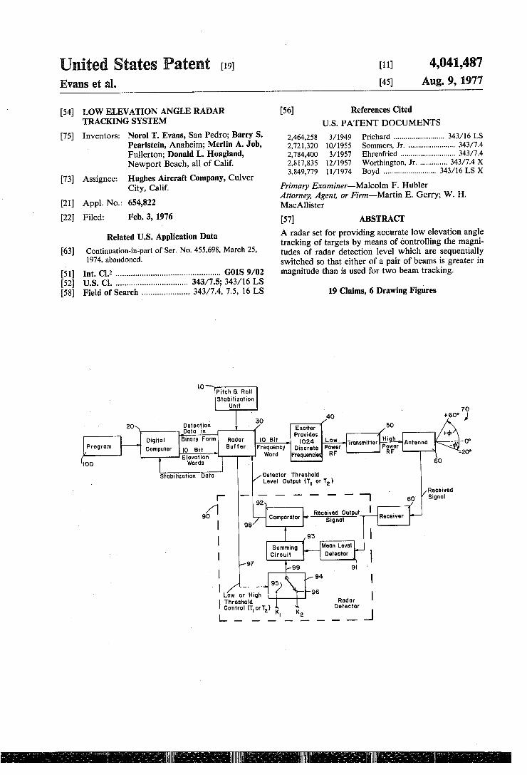
FIG. 1 is a schematic diagram of a radar system in accordance with this invention. FIG. 2 is a representation of seuquentially switched
antenna lobes in elevation by the radar system. FIG. 3 is an algorithmic representation of several
routines denoted as FIGS. 3a, 3b and 3c and converted into machine language to program a computer for rapid control and operation of the radar system. For conve nience of discussion FIGS. 3a, 3b and 3c will be referred to hereinbelow as FIG. 3. FIG. 4 is a detailed block schematic of the radar buf
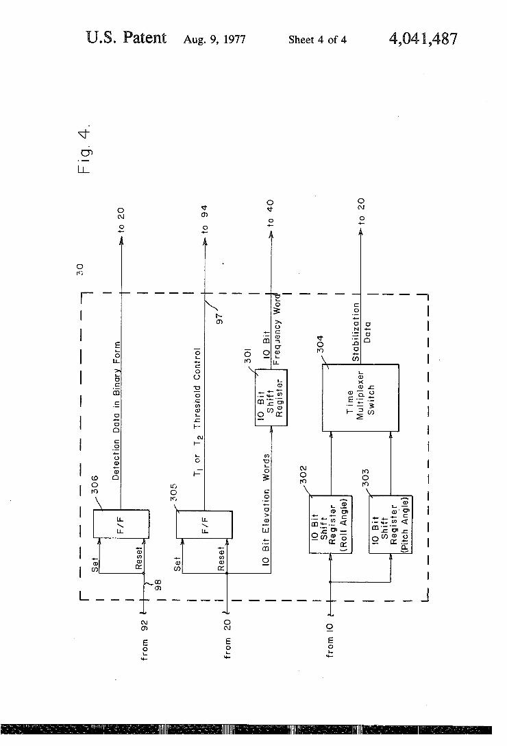
fer shown in FIG. 1.
DETAILED DESCRIPTION Referring to FIG. 1, a radar transmitter-receiver sys
tem is shown, inclusive of the inventive subject matter, used for elevation beam steering.
Stabilization data source 10 comprises the pitch and roll control unit for input to the radar system which feeds data into radar buffer 30 in conventional manner. Such stabilization data is provided as an input to digital computer 20 through buffer 30 in form acceptable by computer 20. Computer 20 provides ten bit binary words to radar
buffer 30 input corresponding to the required degrees of elevation of the radar antenna in accordance with table (1) hereinbelow generally illustrating several degrees of antenna elevation and their binary word equivalent, as exemplary. Such stabilization data provided by source 10 is
dumped into 10 bit shift register 302 for temporarily storing roll angle information and into 10 bit shift regis ter 303 for temporarily storing pitch angle information. Input data to registers 302 and 303 is supplied to com pensate angular deviation of pitch and roll with respect to reference plane coordinates, which coordinates are provided in computer program 100, and time multi plexer switch 304 will enable roll and pitch angle infor mation to be supplied in sequence to computer 20, Reg isters 302 and 303 and multiplexer 302 are shown in FIG. 4.
ANTENNABEAMELEVATION COVERAGE Degrees of 10 Bit Binary Form
Beam Elevation Elevation Word --60.0 0000000000 --59.9 0000000001
O 010100100 (1) -20.0 11111111
Computer 20, by receiving the stabilization data, is enabled to compute the exact elevation of the horizon. Radar buffer 30 in the return path and resulting from
an output of the detector, to be hereinbelow described in greater detail, provides detection data in binary form as an input to computer 20 for processing thereby. Radar buffer 30 converts the ten bit binary elevation
words into ten bit frequency words provided as input to exciter 40. Exciter 40 is designed to provide 1024 dis crete frequencies, each frequency representing a spe cific elevation position of the radar antenna correspond
4,041,487 S
ing with the elevation position range shown in table (1). Accordingly, there are 1024 beam positions covering an 80 elevation range in 0.078 degree steps. The computer adds a half beamwidth or a value of 6
of the 0.078 degree steps to the computed horizon value, and this is the lowest elevation angle sent to buffer 30, At the appropriate time, the elevation word in terms
of frequency is sent to exciter 40 for selection of the required discrete frequency. The selected frequency is fed at low RF power to a suitable amplifier within trans mitter 50, and output of transmitter 50 at high power level is fed to radar antenna 60. Antenna 60 has a frequency scan characteristic as to
elevation, so that the selected frequency by exciter 40 determines the elevation angle, as shown in exemplary fashion in table (1), at which the antenna beam, as at 70, is transmitted and/or received. Antenna beam 70 is shown in terms of the earth's horizon at 0, the angle above the horizon indicated as --d', and the angle below the horizon during pitch of the ship bearing the radar system as being -b.
It should be noted that when the radar system is in stalled on a ship the horizon will be constantly changing with respect to the ship's pitch and consequently the zero reference portion of angle d as at 70 will be ad justed with change in pitch.
Referring to both FIGS. 1 and 2, and with specific reference to FIG. 2, a pair of antenna lobes A and B as conventionally transmitted by a monopulse radar sys tem at a predetermined sequential period are shown in elevation, and are representative of antenna beam 70. Though several methods are used for transmitting and
receiving radar energy, in the final analysis it is neces sary to sequentially switch radarantenna 60 to provide lobe pair A and B in a predetermined sequence. Lobes A and B will therefore not be present at the
same instant of time, but generally lobes A and B will be usable to detect higher flying targets at which time switch 94 will be positioned by means of flip-flop 305, shown in FIG. 4, providing output signal at 97 which activates and switches switch 94, at contact 95 in order to obtain normal offset signal and hence a lower thresh old value as seen from table (4)hereinbelow. Either Beam A or B may be used to detect low flying targets in which case switch94 will be positioned at 96 in order to obtain an offset signal higher by 3.db than the offset signal when switch 94 is set at 95 position, and conse quently obtain a threshold level higher by 3.db than the threshold level when switch94 is set at position 95, also as seen from table (4) hereinbelow.
It is therefore obvious that selection of high or low threshold levels will be controlled by buffer 30 and may be predetermined by appropriate time sequence con trolled by computer 20. One method used in conventional monopulse radar
systems is to receive the sequentially switched antenna lobes A and B in elevation. Another method used is to transmit the sum of the lobes as a single beam and re
10
15
20
25
30
35
45
50
55
6 The output of receiver 80 is generally fed to several
components of radar detector 90, as inputs to mean level detector 91 and comparator 92. The output of mean level detector 91 provides a voltage level input to sum ming circuit 93. Data from comparator 92 is processed by computer
20, however such data is inputted to flip-flop 306 shown in FIG. 4 to pass or reject the data in accordance with the logic as stated in the truth table at (5) relative flip flops 305 and 306. Data from flip-flop 306 is passed to computer 20 for processing same, and data from flip flop 305 provided by computer 20 is passed at 97 to switch 94 to change its position as required. Threshold level switch94 is illustrated as a two posi
tion mechanical switch (but may be an electronic type switch), which is positioned either at position 95, which is the normal operational threshold level position, or at position 96 which is the position for low altitude opera tion of the radar system. An offset signal level K, which may be a series of
binary pulses such as those comprising a five bit binary word, is supplied from within detector 90 to terminal 95. Likewise, an offset signal level K2, also a binary word, is supplied to terminal 96 of switch94. Switch94 is controlled as to its position at either 95 or 96, by means of switch command at 97 in order to select threshold Tor T. Accordingly, either threshold level T or T, will be
provided at 98 as input to radar buffer 30. Hence, either T or T, threshold will be provided to buffer 30 by summing the signal obtained at 99 with the detected means level voltage provided to summing circuit 93, the output of summing circuit 93 being fed to comparator 92 to provide either Tor T, threshold. Threshold levels T1 and T are defined by the following equational rela tionships:
T = M --K where T is the threshold level for normal tracking operation
M is the mean level signal provided by mean level detector 91
K is the offset signal level for normal radar elevation operation
and, where typically T might be in the order of 7db.
(2)
T = M + K. where T is the threshold level for
low-altitude tracking operation
M is the mean level signal provided by detector 91
K = K+ 3.db which is the higher offset signal level to raise the threshold level about 3.db above T.
(3)
For a better understanding of the threshold level requirements as inputs to buffer 30, the following table
ceive either the resultant of the sum and difference of 60 shows signals required in terms of beams A and B for the received beam pair. However, in the latter instance two antenna lobes result anyway, so that insofar as developments of the novel approach herein, the cir cuitry within the detector to be hereinafter described would generally be applicable and representative of 65 either method. A signal reflected from a target as sensed by antenna
60 is fed by such antenna to receiver 80.
the two modes of operation of the radar system.
Required for Low Altitude Operational Mode T. detection on Beam A
OR T. detection on beam B.
Required for Normal Operational Mode T detection on beam A
AND T detection on beam B
(4)
4,041,487 7
In the normal operational mode, detection of both beams A and B at threshold level T is required to pro vide date output from buffer 30.
In the low altitude operational mode, detection of either beams A or B at threshold level T is sufficient to 5 provide output from buffer 30. No detailed circuits are required for any of the com
ponents discussed, such as components 10, 20, 30, 40, 50, 60 and 80 as these are known in the art. As to radar detector 90, the components thereof such as 91, 92, 93 10 and 94 are each individuallyknown in the art as circuits, however the method of switching between different threshold levels to provide one pair of beams to be of greater mangitude than the other is not known in the art. 15 Referring to FIGS. 1, 2 and 3, and particularly to
FIG. 3, algorithms from which a computer program designated at 100, are shown; algorithms 100 are di rected to routines to check if single beam tracking is valid, for track smoothing for elevation, and for beam 20 firing routine. The actual computer 20 used was UNIVAC
MODEL 1230. The computer language used is SIMON SYCOL
which is a UNIVAC COMPILER language. The actual 25 computer program implementing algorithms 100 is sub mitted with this specification. The basic concept of the single beam low elevation
tracking technique is to allow a track's range, azimuth and amplitude data to be updated from only one of the 30 two sequentially-lobed beam pairs A or B. In addition, the technique limits the lowest point at which the beam may be fired in elevation. The decision to use a single beam's return, or both beam returns, is based on logic criteria which is described hereinbelow. 35 The logic criteria are functions of target range, maxi
mum clutter processing range of the system, target elevation, and return signal amplitude. As can be seen from the logic criteria and the algorithmic flow dia grams of the FIG. 3, other less critical steps are also 40 taken. For example as the target goes lower in eleva tion, the two sequential beams are brought closer to gether. Although this does make the beam splitting curve less sensitive, it has the advantage of keeping the lower elevation beam from being distorted and hence 45 allows some measure of elevation angle determination through beam splitting.
In the following rules which delineate the single beam low elevation tracking technique, the particular numeri cal values shown are typically applicable for radar sys- 50 tem.
If the target elevation angle, db < 0.6 which corre sponds to about 0.6 beam widths, this angle permits single beam tracking, In order to prevent the lower beam from ever being 55
<0.44, the beam pair center is never <0.56. If the target is at short range (less than 30 nmi) per
form single beam tracking only if the target amplitude is sufficiently high to be representative of a real target. This is accomplished by determining if at least one of 60 the last two updates had an amplitude > 20 db. This criterion prevents false alarm problems, that is tracks running away on noise or on noise spikes.
If the target range is greater than the effective clutter processing limit, for example long range tracking, and b 65 < 0.6 and if it is certain that clutter processing is re quired to detect the target, then the target track is dropped. Such targets are prevalent at long range and
8 are flying low over land and are therefore very low priortiy tracks for the system. If clutter processing is not required for these long range targets then single beam tracking is permitted. Fix the amount of beam movement from update to
update to small change, for example 0.078 when the target elevation angle is < 0.7 such as when multipath can have an effect. Eventually, by following the direc tion, although not the magnitude, of the beam split indications, tracking of the target will be successful. The update rate must be adequate such that target movement does not escape the beam movement avoid ing the production of misses. When d <0.7 decrease the spacing between the two
elevation beams, using the previous spacing. When single beam tracking is permitted, a check of
the returns of each beam is made. If either one has a return which correlates with the track, that single re turn is used to update the track. The track's elevation angle is kept constant. If both beams have correlating returns, then beam splitting and track update proceeds as normal, except, as discussed above, in that the amount of elevation movement permitted is restricted. The essence of this point is that single beam tracking allows, but does not require, a detection from a single beam to be used to keep a target in track. FIG. 4, shows the three inputs and four outputs there
from corresponding to FIG. 1. As can be seen, the components are standard storage or shift registers, flip flops and a time multiplexer, all known in the art, to provide the means for interfacing with components of FIG. 1 designated as 10, 20, 40,92, and 94. It should be noted that the computer program includes the handling of the various inputs and outputs shown in FIG. 4. The threshold control signal is provided as shown in
FIG. 1 by switching between positions 95 and 96 of switch 94, which threshold levels T or T are fed at 97 to switch 94 through flip-flop 305 by input from com puter of a particular logic level at 20 which logic level is temporarily stored in flip-flop 305 (FIG. 4) until com mand by computer is issued to switch to another of the binary logic states to select the other threshold as needed. It is obvious that flip-flop 305 is provided to enable temporary storage of a logic state until required to change position of switch 94.
Further, table (4) shows operational modes involve threshold levels, and that the threshold control necessi tates the change of position of switch94 and the thresh old control level with each change in antenna elevation.
Input data coming from pitch and roll stabilization unit 10 is shown in FIG. 1 as being inputted into buffer 30. The specification already states that the stabilization data is in form acceptable by computer 20. The binary form of data, since we are using a conventional digital computer is well known in the art. It is therefore inher ent in the needs of this system that some storage of the binary data, coming from unit 10, as provided by shift registers 302 and 303 will have to be included, and that a time switching device such as time multiplexer switch 304 to switch the roll angle data words and the pitch . angle data words, would have to be provided in the buffer so as to feed such words into the computer for storage and use. It should be noted that computer 20is able to correct for pitch or roll by correcting the an tenna angle by taking the data temporarily stored in registers 302 and 303 in sequence, accomplished by multiplexer 304. As to the 10 bit frequency word pro vided as input from the computer to exciter 40, the only
4,041,487 requirement would be elevation word information in binary form sent by computer 20 through exciter 40 and ultimately to antenna 60. With respect to flip-flop 306 of FIG. 4, this flip-flop
10 grammed computer activates the switch at the appro priate time to achieve the desired condition, and hence the computer, based on input information received as to angle d level, will command switch 94 to operate as
only provides a dealy or storage of binary pulse, in 5 required. Both the flow diagrams FIGS. 3a–3c and the terms of the binary state temporarily stored therein for actual computer program used, show the part the com providing detection data in binary form to computer 20. puter plays in this regard. As to component 10, this is It is inherent by the showing in FIG. 1 of an input of shown in Radar System Engineering by Ridenour, Ra detector threshold levels T or T2, discussed above, and diation Laboratory Series, Vol. 1, at page 308, McGraw an output of detected data in binary form through the 10 Hill, N.Y. 1947, entitled Shipboard Antenna Stabiliza buffer, implying temporary storage of the binary state tion. Unit 10 calculates the true horizon at two orthogo before sending it on to computer; any binary storage nal points (box and midship) by use of a gyroscope device would do for this purpose but a single one suchas described on page 308. This data is sent through unit 30 flip-flop 306 is shown as satisfying this situation and 15 to unit 20 so that the next radar beam is fired not in implied storage function. Components herein are shown relative but in true direction space. It should be noted in the Radar Handbook by Skolnik, 1979, McGraw Hill, that the computer tracks in true range, elevation and N.Y.. Transmitter 50 is shown at pages 7-44 (Section azimuth coordinates. The pitch and roll units measure 7.5) to 7-48. Antenna 60 is shown at page 13-3 (FIG.3). the deviation in degrees from horizontal. The computer FIG. 3 also shows buffer 30 in block form combined orders a beam fired at a selected elevation and azimuth with computer 20, and transmitter 50 and a frequency position. The buffer corrects these angles based on the generator corresponding to exciter 40. In general, pages pitch and roll angles detected, as aforesaid. The buffer 13-1 through 13-27 show standard ways of building the 30 is simply a temporary storage unit that interfaces frequency scanned radar system. with the real time radar and the programmable com With respect to buffer 30, it is a standard circuit used 25 puter unit 20. Exciter 40 is simply a group of oscillators
for isolating several components of the system from providing the 1024 different frequencies. each other as shown in FIG. 4. It happens to be a conve- It should be noted that the Skolnik textbook at page nient location for utilizing therein a means for switching 22-13 (Section 22.3)discusses the problem of reflections switch 94 to one of two positions. In the illustrated at low elevation angles. It states that very poor per example an electro-mechanical switch94 is used having 30 formance occurs when the beam is pointed one beam contacts 95, and 99 which would be really contacts, a width above the surface. However demonstration by realy coil thereof would be triggered, symbolically actual flight testing, good performance at greater than shown at 97; alternatively a solid state switch could be 0.44 beamwidths above the surface, was exhibited with used. The important consideration is that the pro- the instant system.
i.J. Tiks O - G - gE------------------ 'til Tric CO2 assus
+ki ru U?t tri-ra tiss------- iii.T. At 00 ge
is T : OGO till T. As 0 gues 120 -r, Ug - - - - - - -
21 O) 2. Oui
in 2 v is O J12 - - --------------- 'til 29 rag Ult 260 5
427 .3 is 13 Sui
-'lli Tr. As U18 $32, As U19 * 3: ... is ris G 2 ... --------
k s RAB
E. 52 SS This 22 3 - 23
List TxAs Ou2. sity-Tas tas ----- - - - - - - - - (lit. T, a 28
2 SOU27 " ii is Tk 3 028 tigrOGag +1 is a ( Ö30 -as-Tas us --------- 447 vat Ou32 is 3 . . . . 415. Trad O.J. Pist3 is 52 RE G55 P1537
15S ribs O(36 P1340
3535
: 13.
6. UGO 1.050
s.S. RA-7 - P35s. 55 155 Tr; C 38
tisstrasts i57 T, Ad OC - G
2 P7365
b217 62s
Pi3b2 1030 G6222 PSE-3 SOSO 1622. Plot 8000 P367
(5. 1365 (5627 5626 056222 Se22 367
be kiss 4 is a stre+to+tsk is ess at is is a texx it is 448 - 4 + " "PRCEDURE"CFB
RETUR. R. NPRC cFB
SYS-PROCa, JB SPSness gigs iiii is is a six it is gigs as : . . . . . . . g . . .
; : xxx is is is kei is give is g is . . . . . . . . . . . . . . . . . . . . . . . . . . . . . .
BEAMSPT CACULATES HE TARGE A2MUTH AND ELEWATION DIRECTION COSINS USING MEASUREMENTS TAKEN FROM THE PAIR OF RADAR REURIS SEECE BY TRACK CORRELATION THE STABILIZATION ROUTINE 15 THEN CALLED TO TRANSFORM THESE COSINES FROM TE ANENNA TO THE stable CoorDNATE SYSeM.
ISU's . . . . . REGISTERS
B2B3, B, WAR ABS
NONE As ES
SoTeso strs. RWRK UT Purs m
E3 SERS ONE
WARIABLES NONE
ABES - - - - - - - - SOTUS
pROCEURES REFERENCED SA
PR CEURERA. so
SEUPRZ, ELew BEA SPLIT CINSTANTS is a SEC (N 1. STATE OF TEST TARGET, 1 ?h
s EN A w (SWTTGOM) AZERO- IF AZERO IO ITG P TRA30ia TTG. ZERO IMT CONSTANTS 160 EN A RWKAZBASE) e. les? St. A itRWKAZ- so EN A (TRWKEEASE) in s St. A witRivKE). 160 P RA302s 6
4,041,487 27 28
336 Tr- 0942 s INCREENT BCw IF Sze Reques 77 $337 RP 5.3 077 B O O p a o o o EMU 434 troSlit Piso.3 i85 A537.59370s ENT A WSDTTRNorts4+SIZEREG30SR22 APOS- 077 to so a o O p se o a EMV q34 "Try 05.5 Pitts35 36022 A5725 0725 RP Y-1 USDTROUTG+82+SORBCW-SR2) is 77 3G 42 it, O546 434.3 TR 057 " UPDATE POINTER TO RADAR OUTPUT GUEUE 3G44 Trip 0548 s 435 Sls P636 3603.0 , 55.45 ;P +1 NSDXROUT 3,46 r- 0550 P37 0470 U Au0)4G 00000 COv. A SDWROUTL YMORE 437 R551 Piso 16030 0460 050.460 SR B, w(s)xROUT) 3u5. RP 0552 28 35 is 553 Pt. 25.30 OO6005046 ENT BS W (SOXROU)
43.52. Tri 55 Pill b236.03u 3702.957-02 RP Y- (SDWTRK6CT) - TRACKING BEAM FIRED COUNT 18 434 u7 RA Jub "q3, R. CU17- - - - - - - - - - - - - - RELEASE LOCKOUTS WHILE COMPUTING DELAY 43411 Rx 0 U18 less Xi 4772 BOOUD AGOOOOOOOOOg " " - "RI" -- " " " is 43 Rai Q020 PllS 65030 27535 06763.5 RJP WrcwRXA) so Goto de AY COMPUTATION 43414"RX 0021 "P11477; "660 li AG 0000000000 sL All 4545 rx 0022 pROG-SRC 45.5" R, , 23 P77575.5S0 A55266 3526 Rx5 '3. R.A.- 0.92% -- - - - - - - - - - - - - ------------ - - - - - - - -
: N RXCHAN (RxvicWHSR2) MONITOR as INPUT INTERFERENCE BUFFER SYCOLSRC
RESTORE REGISTERS AND EXIT ENT B2 WRXVS82) eNT a try WS ENT AW (RxivSA) RESTORE AREGISTER
5427 R.A. CO32. Pi.1509-500. P74762. 41'4762 REUR, RIL-a- EXIT Rx I 4343 R 003S END-PROC RX-ra S R GUE - RE- sys-PROC RXe PAMER 72 43.432. Rat 001 sists sists six 4 tests the states & so the stus at subted bott 333- -- 3:-V datests statests 3434 Rx: 000 "2" Ex" ERNAL IN f E R R UP." 332. Rac--000-...-------... . . . . . . . THIS PRocedure Is ENTERED DUE TO THE RECEIPT of 3438 Rat 0005 h AN Ex rerNAL INTEERUPT (DN Cal 2.
43437. Rebe No EFINITE PURPOSE HAS BEEN DEMED FOR THIS 434 J RA. O7 PROCEOURS Use stroRAGE AREA FOR PACES AS -'344. RA-9908 -- -------------- - BEEN RESERVED. &3454 R 0 VO9 TNPUTs 3483 -RA.QU10..... --... REGISTERS-r st Rw OUll NONE
34.57 Rai Qua2 k NCNE 450 ROU23. PROCEURS REFERENCEDan 4S461 R x 0.02% ONE ls3462. R. 3025 "PII502. OOOOO A Gui () 3.0303 PRCURe RXE lesb3 Rall ou26 P50s b5u0 Au030. 0300 TERM RxCHAN OUTPUT 43.454 R. CU27 - Pisuut, "sb5ot ACJOO too go TERM RxcHAN INPUT 434 ob R. 9028 pl505 b77i.0 AU 00 000000 TERM c17 OUTPUTn 365 R. C.29 Plis C6 566-0 000 DJ GOOOO terM c15 INPUT - TERMINATE RADAR MO
4 subi R. 030 Pilsu (7 85.030 2033 (60330 RJP (Ex VexR) a $37, Ra." OU3, " . Pils Jig 60 150 P750 2 115C02 EURN ran 437 . . 032 EN PROC RxE 372 "... - - - - - - - - - - - - - RAN SYSPRC- BB SPS53
3473 + . . . . . . . . . . . . . . . . . . . . . . . . . kit is both its 8 to S7 it is is six b : to test to the 88th to 8 pastset be
45.75 3,76 B NONCORRELATED BEAM RETURNS ARE USED FOR TRACKING
list 77 k when CERTAIN syste: CONDITIONS ARF SATSFEO t; VV TRAN DETERMINES THE WALIDITY OF USING THIS SIGLE S5 BEAM RETURN TECHNiet.
53v 4 T.k.a. 900 REGISTERS S55 ... O - - - - - - - - - - k Bl
to 0 to . . Cw 12 s VARIABLES 357 t., Ous as NONE A : " ' w h ABES
- - - - - sot Ts
s is UTPus REGISTERS
k G. B3 WARIABLES
k NONE - - - - - - - - - - - - s TABLES
NONE - - -
s PROCEURES REFERENCED 2. MONE X
d 300 A.J. G. frce URE FRAN Pl15).2 10i CG23s 4235 ENT A (Su TSL2SA+B4) on 2 SMOOTHEO 04.673
4357. T. P53 Old A025 (3.253 0'. A 253 Y MORE IF YMORE LESS THAN is, DEGREES 06675 353 . . . P5u14 bi030 P75) ii. 5) Eur, SB TRACKNG NOT W A 04.675 353 T. PiSu5 100.0232 3 4.2322 eN. A (STS-RNGP+B4 - PRECTED RANGE 0.1673 33d Tik P5us 473 AU334 31.33% cGw. A 334 Y MORE - IF YWORE RGLT 30 MILES 0.41673 5533 P57 600P75526 523 " JP "f RAN SB rRACKING OK SET FLAG NEG (61573
93.23. T , , P5u2) iO2, 0232b. C42326 hit A Usitts+TAMP-R4) - 1 BACK AMP 0.673 43535 fl. S Pisj2 0470 Acos 0035i 0& A 51 YMORE IF YWORE AMP leg 2008 0.4673. 35 to T. v. P.15022 610 u0 75026 11526 P TRANn SB K GO SET FLAG NEG 0.41673
q353.7". T., & 5 Pi5u2S 0I 232 2326 EN A (STS-TAMP2+B4) - 2 ACK AMPo 0.41675 issu Pisual 04600 A 003.1 to 0.5 COs: A 5 Yess. If YESS AWP GT 2003 s OK 0.4673
4,041,487
465.62 R 875 P21022 23030 D04766 04 4766 rWW (TRTRKTMEF) as 46563 fix 876 ""P2923010 UCAGOOO4 (600; Rsista 4e56 kA 877 F202 3405 O2316 0236 PLY+Grx (SDTSYR+B4) SAVE Y DO SMOOTHED asses re-as-------- - - - - - - - - - - - - a a a m-- - - m -
essa T. A 0679. SM RANGE ages - gEgg------------------------------ r on 1 m. a --------------- - - - - - - - - - ------------- - - - - - - - - - - - - - - - - - - - - - - - - - - - - - - -
467 TR 8:3 Plai 25 00 U2322 3 4.2322 ENE (SUTTsh RNGP+8) a t{6571 "T." 552 Pia 28 5000 "AGOOO2 000062 SHG2a " 6572. The 883 P 1,227 .401097.57 04 4757 st RTRWRKRNGPS) as 673 as P2s 2705757 it SUS: GTRRK-RNGME) - 657 a C$35 P.23 1950 BC-7659.765 . . . . . . sRSCPL (TRTRKRNSDYSAVE MEASUREDEVATION 575 86 P232 62.7572.772 ENTA U (TRABS-APHAB75 ApHAFR551 ABLE (54573 b57 T-3AgBAe P2 GS 9730.06232 (56.232 co, A. (rRAPHAMIN) YMORE IF YVORE USE MIN 0.675
its 577 Ro882. F23. 22.27772 dif2. MUL. URf ABS-ALPA+B7 SKIPs US TABLE VALUE 0.673 6 to Tris (8865. P2035 22039 016232 (56.232 U. TRAPHAMN) - USE MIN WAVE 0.673 set, 587 P2S5 OSO IO 500 St Akita to a TRA, 08:8 Fi237 300 to 757 its? EN: Yogi (trwk+RNGPS) - iss3 TRAeS. TPI 2.jg) 150i"DG23,34233 " " " " "STRXALSDTTSFRNGS BasAWE RANGE SMOTHED -m- - - - -m. top O' Tri, U890 k bos R Us ' ' ' ' SMG0 RANGE RAE 6 cut Tra. O892 s
assisu try 393 patti 50 OG 765 Ottes ENG: X Trry RK+RNGW) as to 89 Fl242 iO7 (c. 4772 Olyta EN A (TRT ABS--BET A+B7) - BETA FROM TABLE 0.41675 q66. TR" (894 PI2, D43 047,50 g75684,476 ON A TRTWRKrTMEF) YMORE- IF YMORE USE MIN 0.67s 662 RA (892 Piaiute 22117 Cuift2 0:4772 (TRT ABS-BETA-87) Ski Pa USE TABLE VALUE 0.67s 63 is 8943 P245 2203 D76 0766 (TRTWRK+TIMEDF) - USE WIN valie O is 67s lel T 0.895 121u 6 203 04766 (44.76 : w witt, KMEOF) as 6615 ti Egs P2 it iOOO AO02 COOOO2 RSG-2s s
losio A 087 P250 406 D 2315 042315 RPY-Q-UX (SOTTS-RNGRB-SAWe RANGE RATE SMoored issir - TR OB98 - - - - - - - - - - - - - - - - - - - - - - - - - . . . . . s m - - - - - - - - - - 662 : A (899 as "t. O90 z 'O.E SELECT at SPECIFIES THE RAOAR SETTINGS FOR FIRING THE b22 Tris O90. x NeX PAIR OF TRACKNG BEAMS BASED ON TARGet AMPTUDE AND s232 rANGE AN Clutter cond to NS 462 RA 93 sk 6625 - 904 -- - - - - - - - - - - - - - - - - - - 4662b a 0.935 s27,906 SA we saler CENTER CHANNEL AMPUDE
4653) is 097 s E653, Ogs "P.235 035) 753 755 RA45 EN G, LX (TRTWRKClOsof) siegs 820 too.32 : , 909 P2152 3112 4753 0.75 ENTY-gtsu (RT RK+CLOGUP) isKIP-Lo WER Is SV. At ER ocs, T , , 09.j P12 u.53 1020 4753 Gil 75s rNT: Aur WR +cogP) PPER Is Saller g53; "T.R, CSS "Piau54"1503O is 5525. “ STR A RAAMPsAWE) W. 37 toss it. A 9 P.255 250 ,753 04753 EN G x TRTWRKCOSOF). Gpose 0. toss tr. 912 P2, 561,000"AOOOOOOOOOO "-" TRG" - - - - "WASJEG, MAKE IT POS "Ogiers 9ts. Ty A 09.1S. P.12.1957-102" D02320.04220 NT A u(surscMT+8). WORD WITH CPODE 0.173 is, GTR 09 it," Pia106052460A7637776.377 " ' " see 6377 AZER KEEP costs oY 47s 6air. 915. P21 u61 3,030 (1620 0562i. aPL YG : TRAAMPSAVE) - CP WAS USED SAVE LARGER 041.75 36s2T "O92"P262 OOOU AISOOO" " ' " ' " NT G" wVAMSK." - - - 37 9te's Tisa Os3 P263.9.02320 02320 ENT P (SOTTSyVABs. GET. VVA . . . . . . 37
tests TR" Ogil" P2064." O300" Ato O42 60002" " ' "Si Ar WWASB305, "" " 'INTO "555 5F I57 4634.5 TRi J95 P12 b5 2200 Acco2 OOO2 MU RMWWA's CONVERT WVA CODE TO OB 37 65.6 Tragile, "F236626.030 0552." "As a TRAAMPSAWe Now AWERE AMPETUDe s to 7 k if P121,067 (70G AOo3s (0.036 St. As 30a No A REGISTER 137 b55 TRA D9 is “P2,070 iOUS J2325.42525". " " 'ENT. Giw (SDT rst AMPS84), , , , a 933. Trial 919 P2 u7i Oi O 1620 (562ol STR Q LTRAAMPSAVE TWO BACK AMP. SAVED. . . 0173 46652 TR 2991 P2.72 "O3OOO" AGODIOOO" " " ' " S. As 155 - " " " " " - " " " ' ". . . . ." . " $73 legs. It is 929. P2 (73.19 CO2320.042320 ENT A (sortstroAA+B4) - WORD WITH TOABIT 041.73 635 TR. 0923.1" 127, 52, GO Af757767.577 - " " - sec 77577 AZEROas KEEP A B IF O OFF () is 73 "bass is g3204. Plau5 26939. P7735. 13735. AD. G. 3600000 AD 15Ds To THIS AMP. 04 1473 i; R 92. P2763. 2325, 2525 sRG (SDTTSrAMPS)-JPDAE HISTORY
8996 - Trial. us2.....- ... . . des 62 R 095 p.277 OOOO AO07 (7 RShe 50s bes. 926. P290 .300 (2326 042326 ENTY-QL (SDTTS-TAMP2+B4) a
kiss E. 3927 P21 20,020 in 757 (4,4757 A Aiur RKAMP3) a -4992. In A-.243. ...P.24 ye.93.999. A0939 GGG939. . . . . RSA, 3GD . . . . . . . . . . . . . . . . . . . tosse T; 29 E3:- 230 A833; 333333 OWs 6es 99. P21 to 20 to 4757 44,757 Sri GTRTRKAMA) as Ave. This AVERAge how , 93 a w w t ob y A (32. m r - Y - SAWe CTR MDE LAST FRED t octe TK (933 s O 93- SA-3. ... 29.992. G320 U-2329 ENT USS-cxA43). o b7, f, g35 P2 IIGS 4020 750 Otto ' ' ' " " T. & URTRKLASTCP) - - 7
bg : A 936 P121i07 4030 )4676 (54676 str 6 w (TRWCPSAVE) a SAVE - TeMP as 2 i575 T (37 " ' " ' " " 4677. This 98 Elie Hese AMs FIRED IN CLUTER MODE is "g3g." - - - - - - - -
67. T. O90 Plaii. 10 002 U232U 3 sese ENT: G STSCP+B). (6702 titgei P2. It tyUOAGICJ C is GO". " " NTP criskAZERO 873 - 092 P22 600 Fe15 12.5i PRA62-YES 67 gas -
to 5 T, 9,4 x S. Cer MOE deMANDED BY HARWARE ses 95
46.707 tra 9:6 sk TRA C61s0626 EEE). oso2 As tist" 23 USO 25, 52050 : A wrvicAG) a 72 467. In 948 Pla1 lit 250 A GOOG3 (OOOO3 SU. A 5 ANOT - If A Nor NOT REQUESTed 72 572 it, 39.9 P25 600 F615 to 250 P TRA 63- REGUested 2 '37A3 Iri. (950 467 95. DELETE INTERRUPT WORD sIT 14 CHECK HERE. D., LATER 3. 92-9. R. 9852- . . . . . . . . . . . . - 3. . G6716 TRSE k IN THE ABSENE OF CUTTER. Moe SelecTION MANTANs the 6717 T1: ... 395 TARGET AWPue ABOVE A MARGINAL AND selo), A SATURA of 62 95.5 xx LEye SY WARYING AMPLIFICATION AND ATTENUATION SETTINGS, 6721. T: 956 . . . . . Ati AiSMIT NERGY is 22,957 623 TiA. 9958. . . . . . . . : a 2 r 9
4672s rT g96 g : - - - - - - - - - - - - - - - - - - - - 1s AVERAGE TARGET AMPLITUDE MarGINAL to 28 Tiva (96. se 75727 "TRA U-52 P25. Iu2OUGHT570, 4757 - " " ? ENTA - - - UttRTWRKTaxpay- - - - - - - - tabel off 577 b70 Tris O983 P217 0700 AO007 0007 . CM A RMNCA2 YRE- F YMORE WARGINAL 5
t673. TrA 954 PI212O 5000 Pais53 2.553 JPRA7 and 47.32 Tri, (965 46733 T. " Ogas IS TOA AMPLIFICATION APPLE
4.675. It is 0979 ------- EcREMENT V VA. By VALUE BELOW MARGINAL AMPETUOE. - - - - - - $675 is O9s umw --- am - so a y -
as ris O9. P230 2200 AOCO2 OGOOl2 viu TRMWWAaCONVERT WWA CEO D8 555. Palisi 2602051757 "it's "" " ' " ' " Of GUTRWRKTAMPAS bS is a :
- SSS is 934 ------ - - - - - - - - - - - - - - - - -r is NE WWA SENG ESS THAN ZERO 86755 - Ris- 09SS- -------------------- - - - - - - - - - - - . . . . . . - - - - -m - V - a wr. a y - - - - a 4678 R. O986 P232 27700 A6074 foot, SUs RNCA2 NEG IF (SNEG, LESS THAN ZERO OS 676. Taka O987 P.2336090 P657 - 25. JPTRA73-8.0 4676 : A 988 k 6762. It A .0959 -- . . . . . . m x set wwA TO mia AtteNUATION 4563 (990 ------ - - - - - - - - - - - - - m 4676. . . .99 P23 1040 A777 767 Ejig-WWASK stres - 992 P23557.tiq"O2320,2525" RSESU(SOTTS-CRECVB4) m a 46766 T 0993 : 4,767 a "0.95 "" - - - - - - SELECT NEXT HIGHER TRANSMIT ENERGY isiu TR 995 : issil 99 P.235 loC24, 232. G232 Rasts ENT is UCSTS-CXM+B4)- 4677. R. 997 P237 00 AO006.3 63 :NP rehpB:4SK: AZEROne AsseMBLE SELECON INEX 46773. "Ti O998 P.214002IUU A30003 COOOO3“r
a EMu. is 77," R. 999 " "P2.1" 550 A403 00063
55AESBSKFe
STRA Sox3-SR2. SKIP g677s R 00 P22 till 00 AOOOO3 00003 AD PHPsi, SK SKP
776 T. J." " ' " " is 77 2 DOES ARGET RANGE LIMIT TRANSMIT ENERGY TO SHORT PULSE STSO "T-" ICE- ------ - - - - - - - - - - - - - - - - - - - - - - - - - -
7. TrA 10 P23 lili (2313 O-233 ENTA (SoTTSRNGS) is SKP --- - - - - - - - W - W - nu- EMU
702 R. jus P2 1550 A Gibs 0.63 stris A (SX3+SR2) is SKIPs 703 “T. "UCS" Piais5." Otto O All tyc OG1c to (Ovis ATRMNPY MORE
(47 y RA 1007 12.5 123 607 (5807 EMT is AU (RTGAGsHers3) is KIP Tobiri, Us FairyTaito P6602 as a " " - PTRf72 sys;
t7 is r, U. P2150 69 Pei 56 2.1564 Pitr A77 a is 77 - T - UG - 70iu T. A lil s EE THESE seAMS, FRED I: RGPO cluteR MODE
47, U2 s W 72 Ra is P2151 1 0000 AQ3 250 Rie2 ENT & gricci h; 5K 7.3 : T : 1 J P2152. 70 Å. O U OC Ot;: A TRARGPoe YMOREa
it. . . "P2ss 5CP52 2S25 P:TRAsia-YES 7uid iv. 'lo s 45 it " " " - - - - - - - ------------ r --- is LDER MYCLUTTER MODE DEMANDED BY BOTHEAMS 7; a 0.8 s
-$72u-TR - og - - - - - - - - - - - - - - - - - - - - - TRA 0690-0692, Ted as 2 72 tra 2 P254 i30 250 s250 ENT A Rw cras ANega NEG, SAYS DOWN 720
"stu22 T, Ital Pass 6000P5555 2.536 - " " ' " P : " " TRA82a Do NO GO WN 72 723 Tri (22 P25s 102 232d O-2320 ENT G. USTSCXMI-84) as 0.973
"sit-it-iss pizist sigot-fissiriassi - - - -r-j- - - - - Raria - selectsp No cluTTER PROCESSING O'I675 87.25 x 29 :455 5- 3. . . . . . . . . . . . . . . ... -------- - ---a wa SELEC LCRMT CUTTER MODE lf s suff" tute r- Pairso - soooo-Agogo toogi Tikass " . SESETTR Trivil SET LOWEST vi DE0 NTEGRATION LEVEl All-CED
783 - Tri ius s "Hisa-ti-ics -------------- - - - - - - - - - - - - set cluTTERMooE INTO OUTPUT CONTROL OR3 IMAGE 7.33 ki i G5 473 "f a P2 is 46 GO A60 Coosa TRA84 Sipe SRMS(RETAINSI2E REGUEST INDICAOR setTING is 735 Trip list 22 1502 a52 2320 e. A STsicXMT-Bs, CHG AS REVE SKIP to
978-tra-09.------------. mm raw reLETE IRA.07.9 THRUTRA 973. PU. EARLIER THE CODF 407 i.7); Tr less THAT SAVES curreR MoDEAS FIRED 37 7.9. Tita. -94. . . m - - - - - - - - - - - m - - - - - am 7 a. IF TRACK ISTENT AWE AND CP WAS USED LAST TIME 0.47s 763 - Till usia... m use S.M. P. At AS USED AST TE 0 list3 7, is , , it is . . . . . . . . . . . 0.447
lives -T: 1 vils P12 as 1029 u04760.04760. IRA83. ENT. A...U.IRTRK-ASICP). CPS E2 . . . 041473. 7 are g is "plaii.6452500A76577676577 SEL"." "637 ANr. Kee Cs 3s ONLY 04 473 477. T.A.A.'s 1265. 6909 Pb:1.23 4221 P RA830s No crp PROCESS IPP 04 473 757 163 lite cit (77) EN A ux (TRWRKSTATUS APOS- F APOS FOT TENT 0-175 75. Its sis. P21167 9.099. P.373 2.75 P TRA882 SE. O. P. 4473 4752", O2 754. RA-93. --------. x Oc AI CLUTTER INTER-PULSE PERIODs BASED ON RADIAL VELOCITY sys"Triggs -- - - - - - - - - - ------ - - - - - - - - - - - - - - - - - - - -
4.755 Tris is 5us P127 0000 A (100 01.0 ENT G s CP ITS MASK 0.4773 "t,756 TRG,5 . PI217 g (520 Oct 76, Ollife EN LS rRTYRKASTCP) ANOTo 0.4773 4757 & 1 to P21.72 6000 Pala.5) 225 UP RA32 curfer Nor USE LASir TIME 0.4773 75 rus; P275 UOU"A27 t27 NT A 2a to MTI RANGE 0.4773 7; a TRA Gay 57 P217 0-6i 0.2322 (2322 co, A List TSRNGP+B4) YLEss IF YLESS MTIPATH 0.177 762 Ta is 529 P.275 - 6 OOU"PS213 21.25" "" P " "TRA53O3" 60 SEE IF RGPC AST TIME 0773
47 as R 0,523 Flaita 110 AC000, 3000 FNT A s Mr. PATH (1773 76, "TR" (52s "P.277 J47. 237 gig.237 CO: A (STS-B YMORE, F YMORE ISS G 1 0-1773 476 tra 0527 P.1220 60 u0 Po250 1225) P RA832se MSS is 0 OR 0.4773 7.66", 525 P220. I51-52333.642333 NT A (SETsur-B4). ANOT - IF ANOT TOTAL MISS (1773 47.67 TR 1532 P222 6100 Pe1373 21573 up RA882- No roTAL MISS USE SAME PP 0.4773 HITO TR Igtiss SF2.203 ICOUGAOIsottist" - " " - ENT Q 600- TOTAL 55S, GET OV FD "ASK 0.77's 771. Tris 10:55 is P224 02 2313 (233 in . U.Su TS+FLAGS-3) AZERO 0.4773 772 Taoist P22 U.5 s.00 Palai 212 P RA830.5e USING Kuige IPP 0477s
i.773 tria Osit P226 8500 P.127 227 JP RAt soo Nor USING KLUDGE PP GET ONE (41773 77, TR OG547 P227 3 24 O2323 (42323 ENT Y-3, 5 TTSERIPPB4) AZERG- IF AO SAME IPP OT3 4775 a 0.55. P220 blo C9 P81372 12372 P RA38 GO STORE PP 0477s
rty to TRA U-553 - Pizzi tsuo PEI2ir-227 TRAB30s Jr. tras goos GET ANOTHER IPP Ots 773 777 R. i0 is58 P222 6000 ré1372 1237.2 P RA8801 G0 STORE PP 041773 your “Ugs59 "Patzis (CU20 yC476) qq.75G TRA83O3 ENT LP Utrf RK+ASTcp a 0477s 7io Rs 0.52 P212 200 Act (OO SU. A 00 A2ERO IF AZERO, RGPO ot773 702 trassr225 5000 Psas 1225 P TRA832s. Go SET UP NEW Wellor Y 0477s 7.3 TRA is 588 P2128 6100U P6123 lal23. P RAB311 G CECK Frter FAG 0477s
51 What is claimed is: 1. In a radar system having a buffer circuit and a
receiver, the system providing a pair of sequentially switched radar beams, a radar detector comprising in combination: switching means electrically connected to the buffer
circuit, for switching between two offset control levels provided by said radar detector;
a summing circuit, connected to the switching means, responsive to received signals processed by the radar system and to a signal output from the switch ing means;
a comparator circuit, having an input connection thereto from the summing circuit and having an output connection therefrom to the buffer circuit; and
a mean level detector circuit, the input of which is connected to the output of the receiver and the output of which is connected to an input of the summing circuit.
2. The invention as stated in claim 1, wherein the switching means switches said pair of radar beams with respect to angular elevation.
3. The invention as stated in claim 2, wherein the switching means enables the detection level attributable to either of the beams to be greater in magnitude by about three decibels.
4. The invention as stated in claim 1, wherein voltage output from the mean level detector circuit and the voltage outputs from the switching means are summed by the summing circuit to provide two different thresh old levels to provide the different magnitudes of the switched beam pair.
5. The invention as stated in claim 1, including a radar buffer responsive to output signals from the comparator circuit and providing switching control for the switch ing means.
6. The invention as stated in claim 1, wherein said radar detector provides equal threshold levels and con sequently signal levels of said sequentially switched pair of radar beams for enabling tracking at elevation angles higher than the low elevation angles.
7. The invention as stated in claim 1, wherein the system inhibits the lower of the pair of switched beams from being less than 0.44 in angular elevation.
8. The invention as stated in claim 1, wherein the
4,041,487
10
15
20
25
30
35
45
system inhibits the center of the pair of beams from . being less than 0.56 in angular elevation.
9. The invention as stated in claim 5, including: an exciter responsive to output signals from the radar
50
55
65
52 buffer for providing a plurality of discrete frequen cles;
a radar transmitter responsive to output signals from the exciter for amplification of the discrete frequen cies; and
a radar antenna responsive in elevation control to signals from the radar transmitter over an elevation range of 80'.
10. The invention as stated in claim 5, including a pitch and roll stabilization unit for providing input sig nals to the radar buffer.
11. The invention as stated in claim 5, including a digital computer for providing a plurality of ten bit words to the radar buffer so as to control elevation, and being responsive to detection data and stabilization data provided through said radar buffer.
12. The invention as stated in claim 9, including a radar receiver responsive to received signals provided by the radar antenna.
13. The invention as stated in claim 12, wherein the signals received by the radar system are provided as outputs from the radar receiver, and as inputs to the mean level detector circuit and to the comparator cir cuit.
14. A method for controlling of threshold levels and hence the required signal levels of a pair of sequentially switched radar beams of a radar system having a buffer circuit, comprising the steps of:
switching, in a predetermined time sequence, the threshold levels;
comparing the switched threshold levels with signals received by the system; and
feeding the compared signals to the buffer circuit. 15. The invention as stated in claim 14, including the
further step of controlling the sequency of switching by a computer.
16. The invention as stated in claim 14, where in the step of switching the detection level between said beams is greater in magnitude by about three decibels.
17. The invention as stated in claim 14, wherein the step of switching the lower of said beams is controlled to inhibit its angular elevation from falling below 0.44'.
18. The invention as stated in claim 14, wherein the step of switching the center of the pair of beams is con trolled to inhibit its angular elevation from being less than 0.56.
19. The invention as stated in claim 15, including the further step of programming the computer for execu tion in proper order of the foregoing steps.


![opened [1], [14] › cehv › documents › 19-IEEETEIEI-12No.2176 … · IEEE Transactions on Electrical Insulation, Vol. EI-12, i4o. 2, April, 1977 TRANSIENT DRIFT DOMINATED CONDUCTION](https://static.documents.pub/doc/80x56/5f206e1229b4a341520c2cb3/opened-1-14-a-cehv-a-documents-a-19-ieeeteiei-12no2176-ieee-transactions.jpg)


