44

•
UNITED STEEL DECK, INC. DECK DESIGN DATA SHEET
No. 16 CUSTOM DECKS
THESE SECTIONS ARE ALL DIFFERENT. NOT ONE IS A " STANDARD" DECK SHAPE . BUT, THEY DO HAVE ONE THING IN COMMON - THEY WERE ALL MADE AT UNITED STEEL DECK, INC. TO SERVE A NEED FOR A PROJECT THAT REQUIRED A CUSTOM DESIGN. CALL IF YOU HAVE AN APPLICATION THAT REQUIRES CUSTOM BENDING. YOU MIGHT BE PLEASANTLY SURPRISED AT THE SAVINGS A SPECIFICALLY ENGINEERED PRODUCT CAN PROVIDE.
16 GAGE FORM DECK - USED TO BUILD A PIER WITH AN 18" SLAB.
I· 9" Yl 9"
·1 1 .J\J LJ LI 2"
I· 24"
-, f
12 GAGE TOP AND 16 GAGE BOTTOM CELLULAR DECK USED TO SPAN BETWEEN BOTTOM BEAM FLANGES IN A POWERPLANT. VERY THICK SLAB - FLAT UNDERSIDE LEFT EXPOSED.
L~=t 1
3" 1 9" 1 3" I ." • '4 •.••.
12 GAGE 28 ' LONG DECK WAS USED TO ROOF AN EXISTING TANK. 15" SLAB; 6" WIDE RIBS USED AS REINFORCED CONCRETE JOISTS AT 15" CENTERS.
I. 10.5" ·1
rL t4.5"
I. 16" -I 16 GAGE LONG SPAN CANOPY DECK MADE FROM PREPAINTED STEEl.
CUSTOM DECK SECTIONS ARE AVAILABLE IN LENGTHS UP TO 34' IN A WIDE VARIETY OF FINISHES. QUOTES CAN ALSO BE PROVIDED FOR STAINLESS , ALUMINUM , AND FOR BENT PLATE UP TO Y2" THICK. A COMPLETE LINE OF ROOF DECK, FORM DECK, LONG SPAN DECK, AND COMPOSITE FLOOR DECK IS ALSO OFFERED - WRITE FOR OUR CATALOG.
~~ r- ~ ""_ .JtK.\; I- ~ MEMBER
...... :"--"'--H,·~';.,·I~~·;.~;)-""-=[=J"""'-'-l-...J NICHOLAS J. BOURAS, INC. ~ ~o. BOX 662. 475 SPRINGFIELD AVE.
SUMMIT. NEW JERSEY 07902-0662 (908) 277-1617

•
SPEED AND ACCURACY DOWN TO
THE LAST DETAIL. FabriCAD II from Slruclural Soflware. FOr fasler, more accurale delailing, dra\l on FabriCAD II. h', lhe delailing program lhal reneelS lhe aclUal problems lOU face in C\ery job - and solves lhem.
Emering infomlmion is simple. because inpul follows lhe ereclioo plan. Based on lhe E-plan, FabriCAD II nOl only accuralely compleles delails. il allows for a wide variely of shop and field conneclions. h also generales anchor boh plan;. E·plans, bracing delails and e1evalion views. And because all dimension; and conneclions can be easily ~-diled, change orders are a breeze.
FealUres like lhese mean lhe end of loog wailS for shop drawings. Wilh FabriCAD II. you can complele 1\10 or lhree limes as many sheets per day using lhe same personnel. And because all our programs are designed for IBM conlpulers and conlpalibles, no special lraining is necessary.
Call or wrile wday for more infomlalion on FabriCAD II and Olher SlruclUral Software programs. including: • Eslimaling- Generales moreacL'Urale eslimale; for hiRher profil margins . • Im-emory Conlrol. Produclion Comrol and Purchase Drders - Malerial
=~::~fsrograms lh31link purchasing j.w;'h 7.72". Ill- are an authorized reseller
of NOl'ell NelWare alld El'erex computers. Slruclural Soflware _ _ __ Company. 5012 Plammion Road. P.O. Box 19220. Roanoke. STRUCTURAL SOFTWARE CO. VA 24019. (800) 776·9\\8 SOFrWAOE FO. THE STHI INDUST.Y

MODERN STEEL CONSTRUCTION
Volume 32, Number 1
Ti,e brick- and limslotle-clad researcll cellter at Children's Ilospital was essentially desiglled as a speculative lab and office space, alld tllell retrofitted to meet the hospital's cont;,wally eluurging netds. For more j"formatloll apt this ""'que design, see the story beglllllll'g all page 16.
Modern St991 Construction. Published monthly by the American Institute of Steel Construction, Inc. (AISC).
Executive. editorial , circulation office: One East Wacker Dr., Suite 3100, Chicago,lL 6060' -2001 . AdvertIsing office: Panis/3M, 7161 North Cicero, L,ncolnwood, lL 60646.
Subscnplion prtCe: Within the U.S.-5lngle ISSUes $3; 1 year
$30; 3 years $85. Outside the U.S.-single issues $5; 1
year $36; 3 years $100.
Postmaster ' Please send address changes to Modem Steel Construction, One East Wacker Dr., Suite 3100, Chicago, IL 60601 -2001 .
Application to mail at second-class postage
l rates IS pending at Chicago, IL (and at addltonal matling offices).
4 1 Modern Stl.oel Construction I January 1992
January 1992 -----
FEATURES 10 PRESCRIPTION FOR HEALTH-CARE DESIGN
Since the mid-1970s, designers have increasillgly tllrned to steel to help brillg hospital projects in 011 budget
16 FLEXIBILITY CRUCIAL FOR HEALTH-CARE DESIG By creatillg a new research facility that readily accommodates cilallge, the designers met all of the owner's criteria
20 SPECIAL DESIGN ISOLATES VlBRA TION To eliminate lIoise and vibratiolltransmission to the oCCl/pied space below dllring constrllction, the desigllers isolated the Ilew constructioll with TS stllb colllmllS topped with neoprene pads
26 REHAB CENTER DESIGNED FOR GROWTH Lnrge Vierendeel trusses were used to meetllllllsual program requirements in all addifionto an acute care and rehab cell fer in Atlanta
32 TIGHT SITE COMPLICATES CONSTRUCTIO Site resfrictiolls, a fast-track schedule and the need for flexibility all he/ped steer the project to a steel soilltion
NEWS AND DEPARTMENTS 6 EDITORIAL
8 NEWS • Updated Gaylords and
Stallmeyer Text Covers ASD&LRFD
• Wind Load Provisions • Vibration Lecture
Continues
9 STEEL CALENDAR
37 SOFTWARE FOR FABRlCA TORS AND DETAILERS
42 ADINDEX
•
•
•

.::>
.;0
.n .,. • J
•
•
•
HISTAR@ A new generation
of rolled beams and column shapes
for economical steel construction.
Once aoaln, AABEO leads the Industry by featuring a trendsetl lng combination of mechanical, chemical and technological properties·
Inc.
JJnlOVIl1'OIII or ITIIL COlO .. RUCnON PRODUCTS.
• HIGH YIELD STRENGTHS (up to 65 KSI) . even 'Of ultra-heavy sections.
• OUTSTANDING TOUGHNESS PROPERTIES
• EXTREMELY LOW CARBON EOUIVALENT - ensures eKeel· lent weidability
A NEW PROCESS ... OST.
The secret is In ARBEO's revolutionary new In-li ne CST process
OTHER RECENT A~BED INNOVATIONS:
ARBED·ROllED ..a-, 4. ·, and "TAILOR·MADE" (WTM) serles -f.mous for high section moduli, gr •• t 1.leral buckling resistance, and big s.vlngs In fabrlcallon costs and weights These products are also available In the new HISTAR quality as is our standard WF series and H BEARING PILES
NEW LlTEAATURE AVAILABLE
Send now lor complete data on all these AABED products, contact Trade AABED. INC., 825 Third Ave., New York, NY 10022. (212) 486-9890, FA.X 2\2-355-215912421 In Canada: TradeAABEO Canada, Inc., 3340 Malnway, Burlington, Ontario, Canada L7M 1A7 (416) 335-5710, FAX 416-335-1292
Editorial Staff Scott Melnick,
Editor
E
Patrick M. Newman, P.E., Senior Technical Advisor
Cynthia J. Zahn, Senior Technical Advisor
Editorial Offices Modern Steel Construction One East Wacker Dr. Suite 3100 Chicago, IL 60601-2001 (312) 670-5407
Advertising Sales Pattis-3M 7161 North Cicero Lincolnwood, IL 60646 (708) 679-11 00 FAX (708) 679-5926
AISC Officers Stephen E. Egger,
Chairman Frank B. Wylie, III,
First Vice Chajrman Robert E. Owen,
Second Vice Chairman Robert H. Woolf,
Treasurer Neil W. Zundel,
President David Ratterman,
Secretary & General Counsel Lewis Brunner,
Vice President, Membership Services
Cecrhard I-Iaaijer, Vice President, Technology & Research
Morris Carniner, Vice President, Finance/ Administration
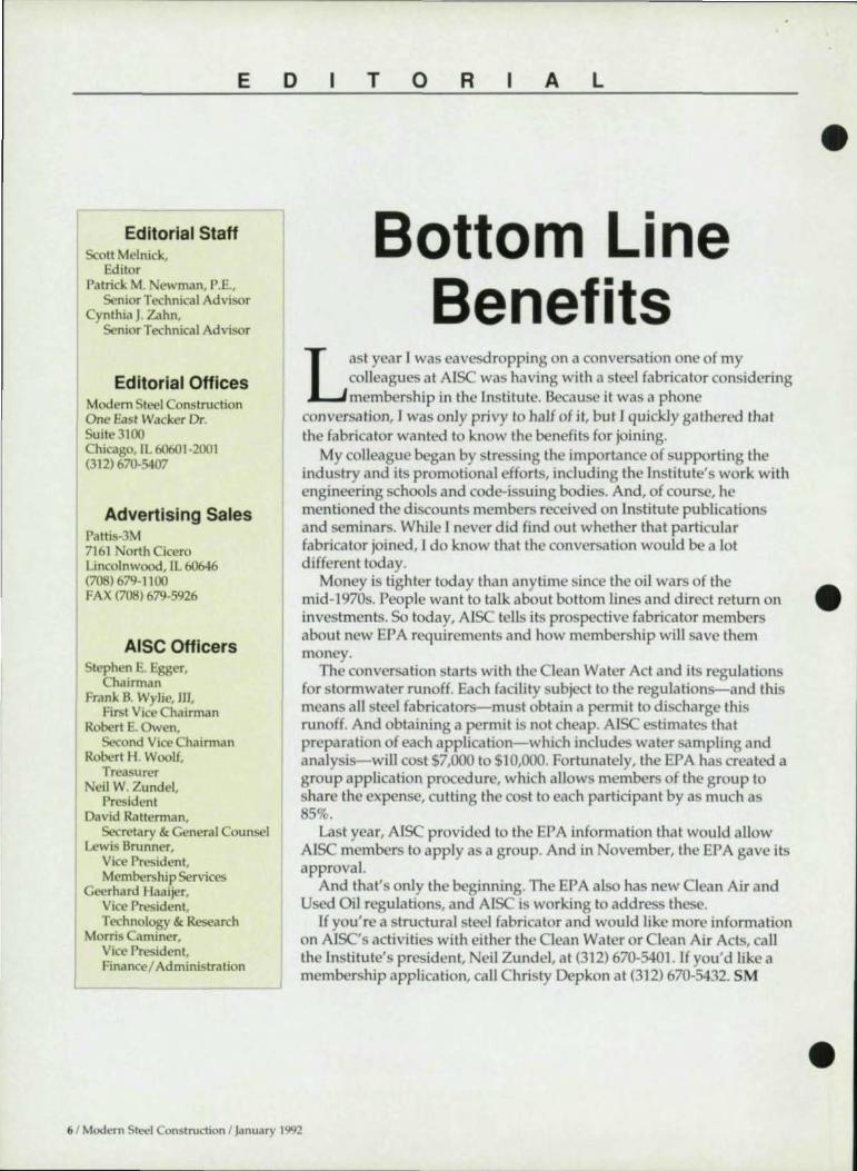
o T o R A L
Bottom Line Benefits
L ast year I was eavesdropping on a conversation one of my colleagues at AISC was having with a steel fabricator considering membership in the Institute. Because it was a phone
conversation, I was only privy to half of it, but I quickly gathered that the fabricator wanted to know the benefits for joining.
My colleague began by stressing the importance of supporting the industry and its promotional efforts, including the Institule's work with engineering schools and code-issuing bodies. And, of course, he mentioned the discounts members received on Institute publications and seminars. While I never did find out whether that particular fabricator joined, I do know that the conversation would be a lot different today.
•
Money is tighter today than anytime since the oil wars of the mid-1970s. People want to talk about bottom lines and direct return on • investments. So today, AISC tells its prospective fabricator members about new EPA requirements and how membership will save them money.
The conversation starts with the Clean Water Act and its regulations for stormwater runoff. Each facility subject to the regulations-and this means all steel fabricators- must obtain a permit to discharge this runoff. And obtaining a permit is not cheap. AISC estimates that preparation of each application-which includes water 5<1mpling and analysis-will cost $7,000 to $10,000. Fortunately, the EPA has created a group application procedure, which allows members of the group to share the expensc, cutting the cost to each participant by as much as 85%.
Last year, AISC provided to the EPA information that would allow AISC members to apply as a group. And in November, the EPA gave its approval.
And that's only the beginning. The EPA also has new Clean Air and Used Oil regulations, and AISC is working to address thesc.
If you're a structural steel fabricator and would like morc information on AISC's activities with either the Clean Water or Clean Air Acts, call the Institute's president, Neil Zundel, at (312) 670-5401. If you'd like a membership application, call Christy Oepkon at (312) 670-5432. SM
• 6 / Modem Steel Construction I January 1992

•
•
•
S~Ill/ISDS -Ranks #1 in Earlhquake Engineering
A recent (October, 1990) ENRlMcGraw Hill survey of the Architecture/Engineering/Construction industry ranks ST AAD-Ili/ISDS, from Research Engineers, as the # I structural engineering software today.
Whether it is a Single beam or analysis of a 3D multistory structure for seismic response, ST AAD-Ili/ ISDS has been the engineer's # I choice - since 1978.
Today, Research Engineers, with six offices on four continents, is making the world's knowledge available to the industry - with continuous implementation of the latest technology.
Also introducing AutoSTAAD- structural drafting, model generation and STEEL/CONCRETE/TIMBER detailing within AutaCAD,
RESEARCH ENGINEERS WORLDWIDE
State -of-the-art dynamic/earthquake engineering facilities include the world's fastest and most accurate eigensolution algorithm, response spectrum capabilities with SRSS and CQC modal combinations, numerically efficient plate finite element to model shear walls and rigid diaphragms, automatic generation ofUBC loading, static/animated mode shape plots, direct combination of static/dynamic analysis results with fully integrated implementation of STEEUCONCRETEITIM BER Design based on American and ten other Foreign Codes.
II. I • i
STAAD-ITUISDS - #1 For a Reason.
....Rese.rch I11III CC Engineers
STAAD-III CIVIL50FT A reputation you can build on.
For Information, call I-BOO-FO R-RESE 15H-1 N Batavia Street .Orange.CA 92667 Phone: (714) 9H-2500 Fax: (714) 9H-477 I
UK.: Ra clreh [n, !nee" (ElirOflCll~ 19 Lan.downe COOl"" ~hWtl P.Q..d, Puriq So.wrer eM leo !'toone; (081) 76) . , ]9) Fu: (081) 76 ) ·' }19 Teu 9191 1 1 fRANCE: Rclurch En, ineen. 18 rve de Mora .... '8800 FlACEY Phone: 17 17 51 61 fax: l7 17 11 61 GERMANY; Raurch Entlneen. WiiheIm-Bu.c.h.Scr. )), 6140 BfNSHEIM ) AUERBACH f'horoe: 06151 19517 faIC 06lS I 751)7 INDIA.: Raurdt En, 1neen "'"- L~. <t06 Dalla Ro.d, Cakuna 700 011, Phone; H 891 1 Telex: 11 1 101
-----------------------
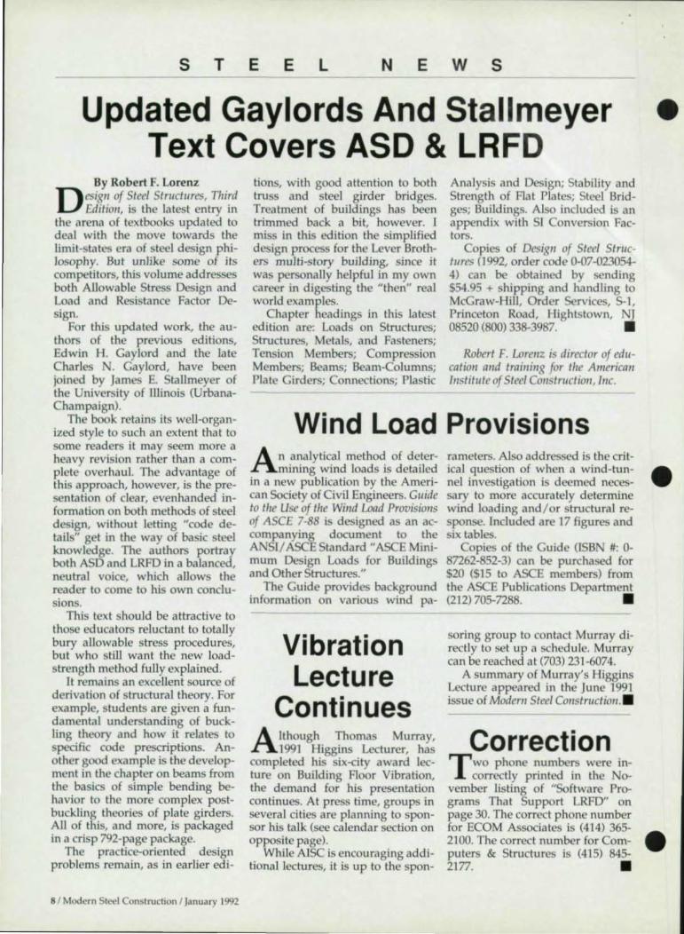
s T E E L N E w s
Updated Gaylords And Stallmeyer • Text Covers ASO & LRFO
By Robert F. Lorenz
D esi81l of Steel Structures, Third Editio", is the latest entry in
the arena of textbooks updated to deal with the move towards the limit-states era of steel design philosophy. But unlike some of its competitors, this volume addresses both Allowable Stress Design and Load and Resis tance Factor DeSign.
For this updated work, the authors of the previous editions, Edwin H. Gaylord and the late Charles . Gaylord, have been joined by James E. Stallmeyer of the University of Illinois (UrbanaChampaign).
The book retains its well-organized style to such an extent that to some readers it may seem more a heavy revision rather than a complete overhaul. The advantage of this approach, however, is the presentation of clear, evenhanded information on both methods of steel design , without letting "code details" get in the way of basic steel knowledge. The authors portray both ASD and LRFD in a balanced , neutral voice, which allows the reader to come to his own conclusions.
This text should be attractive to those educators reluctant to totally bury allowable stress procedures, but who still want the new loadstrength method fully explained.
It remains an excellent source of derivation of s tructural theory. For example, s tudents are given a fundamental understanding of buckling theory and how it relates to specific code prescriptions. Another good example is the development in the chapter on beams from the basics of s imple bending behavior to the more complex postbuckling theories of plate girders. All of this, and more, is packaged in a crisp 792-page package.
The practice-oriented design problems remain, as in earlier edi-
8/ Modern Steel Construction I January 1992
tions, with good attention to both truss and s teel girder bridges. Treatment of buildings has been trimmed back a bit, however. I miss in this edition the simplified design process for the Lever Brothers multi-story building, s ince it was personally helpful in my own career in digesting the "then" real world examples.
Chapter headings in this latest edition are: Loads on Structures; Structures, Metals, and Fasteners; Tension Members; Compression Members; Beams; Beam-Columns; Plate Girders; Connections; Plastic
Analysis and Design; Stability and Strength of Flat Plates; Steel Bridges; Buildings. Also included is an appendix with SI o n version Factors.
Copies of Desi8" of Steel Structures (1992, order code 0-07-023054-4) can be obtained by sending $54.95 + shipping and handling to McGraw-Hill, Order Services, 5-1, Princeton Road, Ilights town, J 08520 (BOO) 338-3987. •
Robert F. wre"z is director of educatioll a"d trailli"8 for the Americall Illstitute of Steel COllstruCt iOIl, IIlc.
Wind Load Provisions A n analytical method of deter
mining wind loads is detailed in a new publication by the American Society of Civil Engineers. Guide to ti,e Use of the Willd Load ProvisiOl/S of AsCE 7-88 is designed as an accompanying document to the A SI/ ASCE Standard" ASCE Minimum Design Loads for Buildings and Other Structures."
The Guide provides background information on various wind pa-
Vibration Lecture
Continues Although Thomas Murray,
1991 Higgins Lecturer, has completed his s ix-city award lecture on Building Floor Vibration, the demand for his pre entation continues. At press time, groups in several cities are planning to sponsor his talk (see calendar section on opposite page).
While AISC is encouraging additional lectures, it is up to the spon-
rameters. Also addressed is the critical question of when a wind-tunnel investigation is deemed necessary to more accurately determine wind loading and/or structural response. Included are 17 figures and s ix tables.
Copies of the Guide (ISB #: 0-87262-852-3) can be purchased for $20 ($15 to ASCE members) from the ASCE Publications Department (212)705-7288. •
soring group to contact Murray directly to set up a schedu le. Murray can be reached at (703) 231-6074.
A summary of Murray's Higgins Lecture appeared in the June 1991 issue of Modem Steel COIlstructio" .•
Correction T wo phone numbers were in
correctly printed in the November listing of "Software Programs That Support LRFD" on page 30. The correct phone number for ECOM Associates is (414) 365-2100. The correct number for Computers & Structures is (415) 845-2177. •
•
•

w ·ZJ . ,T. eT. oJ
•
•
•
s T E E L
January 12. Workshop on High Strength Bolts, Washington, DC. Contact: Frederick D. Hejl, Engineer of Materials and Construction, Transportation Research Board, 2101 onstitution Ave., .W., Washington, DC 20418 (202) 334-2952.
January 12-16. Transportation Research Board (TRB) 71st Annual Meeting, Washington, DC. 237 sessions featuring more than 1,000 research papers and presentations. Contact: Transportation Research Board, 2101 Constitution Ave., N.w., Washington, DC 20418 (202) 334-2934.
January 22. Northeast Steel Bridge Forum, Cromwell, CT. Topics include: heat straightening of damaged girders; quality control for welding high-strength steel; and alternative fasteners. Contact: Camille Rubeiz, Steel Bridge Forum, c/o A1SI, 1101 17th St.,
. W., Suite 1300, Washington, DC 20036 (202) 452-7190.
January 23. Southeast Sleel Bridge Forum, Ft. Lauderdale, FL. Presentation on Aesthetics & Curved Bridge Girders. Contact: Camille Rubeiz, Steel Bridge Forum, c/o AISI, 1101 17th St.,
. W., Suite 1300, Washington, DC 20036 (202) 452-7190.
January 23. Value Engineering for Low-Rise Buildings (breakfast meeHng), Milwaukee. Sponsored by AISC and the Society of Iron & Steel Fabricators of Wisconsin . Contact: Dave Matthews, Ace Iron & Steel, 5118 North 124th St., Milwaukee, WI 53225 (414) 466-9200.
January 27-28. Welding Structural Design two-day seminar,
ew Orleans. Designed to provide engineers and welding inspectors a greater understanding of weld mechanics and welded engineering structures. Contact: AWS, 550 .W. Lejeune Road, P.O. Box 351040, Miami, FL 33135 (BOO) 443-9353 .
c A L E
February 6-7. Weld ing Stru ctural Design two-day seminar,
ewark, NJ (See January 27-28 listing).
February 9-12. National Association of County Engineers, Frankenmuth, Ml. Annual meeting, management and technical conference, and trade show. Contact: NACE, 440 First St., .W., Washington, DC 20001 (202) 393-5041.
March 3. Bolting Update (cosponsored by AISC and SASF) breakfast meeting in Atlanta. 45 minute description of changes since the issuance of the 1985 HighStrength Bolt Spec. Also includes a review of installation methods for high-strength A325 and A490 bolts.
March 11. Texas Stru ctural Steel Institute Quarterly Meeting, Houston.
March 12. Northeast Steel Bridge Forum, Boston. Contact: Camille Rubeiz, Steel Bridge Forum, c/o AISI, 1101 17th St., N.W., Suite 1300, Washington, DC 20036 (202) 452-7190.
March 18. Earthquake Design (breakfast meeting), St. Louis. Sponsored by AISC Regional Advisory Missouri/Southern Illinois Committee. Contact: Phil Stupp, Stupp Bros. Bridge & Iron Co., 3800 Webber Road, 51. Louis, MO 63125 (314) 638-5000.
March 24. Tubular Sections in Building Construction (co-sponsored by AISC and V SSFA) breakfast meeting in Greenville, SC. Will include design criteria, Type 2 Connections, tube-to-tube connections, design guides, p ractical recommendations and application examples.
March 24-26. American Welding Society Show and Exposition, Chicago. Contact: AWS, 550 N.W. Lejeune Road, P.O. Box 351040, Miami, FL 33135 (BOO) 443-9353.
N o A R
Ma rch 25. Tubular Sections in Building Construction (co-sponsored by AISC and V SSFA) breakfast meeting in Columbia, SC (see March 24 listing).
March 26. Tubular Sections in Building Constru ction (co-sponsored by AISC and VCSSFA) breakfast meeting in O,arlotte, C (see March 24 listing).
March 27. Tubular Sections in Building Construction (co-sponsored by AISC and V SSFA) breakfast meeting in Greensboro, N (see Ma rch 24 listing).
March 31. Bolting Update (coponsored by AISC and SASF)
breakfast meeting in Jacksonville, FL (see March 3 listing).
NSCC Scheduled For
June 3-5
More than 45 semina rs and meetings are schedu led for
this year's National Steel onstruction Conference in Las Vegas from June 3-5. Also, more than 100 exhibitors will showcase products for the design, fabric.1-tion and construction community.
Sessions focus on the specific needs of structu ral steel fabricators, engineers, architects, contractors, owners, public officia ls, erectors, detailers, resea rchers and ed ucators. Topics include: codes and specifications; computerized design; research; project and shop management; inspection and safety; and fabrication and erection procedures. Workshop sessions get down to basics: the nu ts-and-bolts details of designing, fabricating and erecting steel structures.
Contact: David G. Wiley, AISC, One East Wacker Dr., Suite 3100, Chicago, IL 60601-2001 (312) 670-5422.
Modern Steel Construction I January 1992 / 9

H ealth C are D e s g n
Since th e mid-1970s,
designers have increasin gly
turned to stee l to help bring
hospital projects in on
budget
By James Stephenson, P.E., and Kurt D. Swensson, Ph.D., P.E.
10 I Modern Steel Construction I January 1992
Prescription For Health
Care Design
•
Through more than 20 years and 2,000 completed health care projects, Stanley D.
Lindsey and Associates (SDLAL) has found that steel construction consistently provides hospital owners and health care companies quality projects on schedule and under budget. Since 1967, SDLAL has been involved in health care projects ranging from small mobile MI additions to large new hospitals located in almost every state and overseas. Steel structures have provided viable structural systems for almost every one of these projects.
A Brief History Prior to the mid-1970s, hospitals
were primarily concrete framed. Designers felt concrete provided superior protection against fire damage, sound transmission and vibration problems. In addition, floor plans for hospitals at that time were fairly regular with short spans that allowed for economical concrete structures.
In the late 1960s and early 1970s, the widespread use of metal deck in a composite system with concrete slabs and steel beams began a revision of thinking in the health care industry. Another important technical advance at that time was the increased use of spray-on fireproofing. It was found that these two systems together could provide the fire protection and strength of concrete systems, often at less cost. Further, the development of "for profit" health care companies fueled the drive for innovation in construction systems.
With the boom in health care fa-
cility construction, "for profit" health care companies began to see structural steel as the system of choice. Advantages included: speed of construction; universal application; uniform quality control; and limited site labor needs. "For profit" health care companies developed several prototypical hospital plans that facilitated early steel orders and fabrication, eliminating the long lead times that can slow steel construction.
Location also played a role in the move towards steel. Since the ma- • jority of construction was in sma ll communities, concrete in large quantities was not readily available because many communities lacked proper facilities. Steel allowed uni-versal application of standa rd plans. Further, quality control of structural concrete was not a prob-lem with structural steel.
Since steel construction requires less site labor than concrete, general contractors could send construction teams to a particular si te and did not have to depend on a local pool of skiUed labor.
Health care Today Today the health care industry is
facing a new set of challenges and again, structural steel is the right material to meet the industry'S new demands. • Economy. With the advent of
LRFD, partially restrained connectjons, and eccentric braced frames, as well as more efficient floor deck profiles and fireproof-ing methods, structural steel is • providing the economy owners demand. Structural steel's light

•
•
•
weight compared to concrete also provides significant savings in foundation costs as owners are forced to use poorer sites for expansion and new development.
• Flexibili ty / Adaptability. By their nature, steel structures provide more nexibility during design and after construction. The modem high efficiency noor planning required for a profitable health care faci li ty results in "shotgun" girds without regu lar bays. These irregular grids wreak havoc on forming prices but have little effect on steel's economy. Further, noor plans in steel structures are not restrained by shearwalls or large columns required by concrete systems. After construction, steel struc
tures are more easily modified to accommodate the noor penetrations and concentrated loads associated with new equipment or revised area uses. Steel construction also ca n provide for more vertical expansion than concrete construction on an existing structure. Nonstructural components such as HV AC duct, plumbing lines, suspended ceilings, etc., are more easily attached and relocated in steel structures than in concrete structures where embeds and interference with drilled anchors can be a problem . • Speed of Construction. Today's
health ca re construction provides the perfect format for taking advantage of accelerated construction schedu les using structural steel. In renova tion/ addition work,
steel can be ordered and fabri cated while necessary site preparation is completed so no time is lost to the lead time required for structural steel. "Down time" also is a large concern for hospital administrators. Since most steel is prefabricated offsi te, actual "down time" fo r hospita l add itions/ renovations with steel is less than with concrete .
For new hospitals, planning and review are necessarily long term procedures that allow for early
-"!I!!!!Io.:-
Seismic resistance;s becoming i1lcreasingly important fo r hospital projects throughout the Un ited States . S/IO'UUI at top is a partially erected frame fo r a tU."tv hospital jn
California. The con"celiotl silmon above is fo r a project j" a !t igh seismic area.
Modern SK-ei onSlruction I January 1992 / 11

Case Study: Jacksoll Regiollal Hospita l
This fOllr-slory, 170,aoO-sq.-fl., 143-bed hospilal in Jackson , TN, was desiglled for two fllillre expallsion floors. This facility was Ihe firsl ill Ihe area desiglled 10 resisl seismic aclivily dlle 10 Ihe recent COllce", over Ihe aclivily of Ihe New Madrid Falllt.
The sirucillral syslem illchlded slrllcillral lighhueight cOllcrele floor slabs on compasile melal deck and beams and momelll resislalll sleel frames. The roof syslem cOllsisted of lighhvfight illslllalillg cOllcrele 011
permallelll melal form deck sllpporled by simple span beams and cOlllillllOUS girders. The cOIIslruclioll cosl for this projecl, excludillg OWller f"",ished eqllipmelll, was $86 per sq. fl.
steel order and fabrication. After steel erection, the absence of shoring allows for quick follow-up of mechanical and other trades. For a typical steel hospital with 100,000 to 200,000 sq. ft. of space on four to six floors, total construction time from ground breaking to move-in is 10 to 14 months with structural steel. • Seismic Resistance. In the past,
concern with seismic resistance has been reserved for West Coast projects. However, the release of the new Standard Building and BOCA codes has brought seismic
12 1 Modern Steel Construction I January 1992
design issues to the rest of the country. Since hospitals are essential facilities, design for proper structural behavior during and after a seismic event is a major design concern. Structural steel's superior performance during seismic events has been well documented (see "The Performance of Steel Buildings in Past Earthquakes," written by EQE Engineering of San Francisco and available from AISI, 1133 15th St., N.W., Washington, DC 20005-2701). Based on SDLAL's experience,
the mass of concrete structures will result in high seismic design forces • even in areas of low to moderate seismic risk. With concrete fram-ing, the seismic loads will some-times control over wind loads even in areas of low seismic risk. Struc-tural steel's superior ductility and light weight make it the system of choice in any health care project where seismicity is a consideration.
Hospital Prototype SDLAL has worked with archi
tects, owners and contractors since 1967 to develop the most economical structural system for typical health care projects. This system incorporates a structural steel frame and a 5V4" structural lightweight concrete slab on a 2" composite floor deck supported by composite steel beams. The roof system is typically a lightweight insulating concrete slab sloped to drain supported by metal deck and steel beams. The floor and roof construction meet U.L. assemblies 0916 and 0921 respectively, elimi- • nating the need to fireproof the deck.
Lightweight structural concrete is chosen for the floors because it satisfies fire rating requirements with thinner slabs than would regular weight concrete. Compared to a normal weight concrete system, this results in a 25 psf reduction in dead loads, which reduces deck thickness, column loads and foundation sizes.
The lateral load reSisting system typically is welded moment resisting steel frames. Shallow spread footings, in combiJlation with site improvement techniques where required, are used whenever possible.
Case Study: Centennial Hospital Complex
This $105 million project in ashville includes a 14-story hos
pital tower above a two-story parking garat;e and a five-story medical office building connected by a two-story 90' enclosed bridge. The asso- • ciated low-rise ancillary area cov-ers more than five acres.
SDLAL worked with the con-

•
•
•
tractor and architect to analyze numerous concrete and structural steel systems for this project. Struc-
CENTENNIAL MEDCAL CENTER
tural steel was selected for its economy, fl exibility and construction speed . Steel was erected and floor slabs placed on the 200,OOO-sq.-ft . office building in less than six weeks. At this time, the office building is nearing completion and the hospital is in the design phase.
Case Study: Mayfield Community Hospital
This 201,OOO-sq.-ft, five-story hospital in Mayfield, KY, fea tures an integral med ica l offi ce build ing
MAYFIELD HOSPITAL
I I I I I I I I I
IT'S HERE! A Brand NEW Publication For Safe Construction Practice in Steel Floor and Roof Deck Installation
"SOl MANUAL OF CONSTRUCTION WITH STEEL DECK" IS a new and complete guide 10 sale COIiSlruclio It covers responsibilities lor Design , Specillcation, Bundling, Loading, Unloading, Hoisting. Placing. Anaching Placement II! Construction Loads lUerves
as a safely pnmer for CoobII:IDII, EIIc:In. Archlllcts, Engineers and /ntII-1lli
wbu are responiide lor .. e aM "01""" fill !lld In lation
BRAND NEW- FIRST PRINTING SDI MANUAL OF CONSTRUCTION WITH STEEL DECK- No. MC01
Ouanlllw S11 .15 •• "
us Currency Total [
Out 01 Conllnentitl U S Add 1~ ~ Can SOl 101' Spetw ShlPPll'l9
such as Express MilIl , Air Ma~ , etc -addlttOnal
TOTAL ENCtOC 0
N~e ______________________ _ A~e~ ____________________ __
CITY ______________________ __
S~TA~lE:::;:~_;,;;;;;;_--- ZlP' ___ _ C
5,,,,,::d -. J. ~~~~ DECK INSTITUTE ~ d _ PO 80l9506. CllltOfl , OtI lo4Ul1
(2161493-7816
I I I I I I I I L ______________________ J
AL:..OW T W
Modern Steel Construction I January 1992 / 13

and was designed to accommodate the addition of one additional floor. This project is typical of the new emphasis on large ancillary outpatient services in lieu of large number of hospital beds. These outpatient services require large open areas and irregular bays, which make them well suited to structural steel framing.
foundation system was required . SDLAL recommended a structural
mately $78/ sq. ft.
Case Study: Suburban Medical Office Building
The structural steel frame was designed to resist Zone 3 magnitude seismic forces. Substantial savings were realized by the use of steel framing, which allowed shallow foundations in place of deep foundations required by the alternate concrete design. Total construction cost for thjs state-of-theart facility was approximately $l00/sq. ft.
Caste Study: Arab/Guntersville Hospital This four-story, 9O-bed replace
ment hospital in Arab, AL, was originally designed as a concrete structure, which meant a deep
ARAB GUNTERSVILLE HQ PrTAl
steel system on shallow foundations, which allowed the structure to be brought in within budget and allowed the project to proceed. Construction cost was approxi-
This six-story, 113,OOO-sq.-ft. medical office building in Louisville is designed to be constructed adjacent to an existing hospital. The project is scheduled to begin construction in the spring of 1992 with a construction budget of only $65/ sq. ft. To accommodate a possible future expansion of hospital activities, the steel structure is designed for live loads required for hospital occupancy, which are conSiderably higher than the code-required office loads. This design for future flexibility is becoming more common and can be accomplished using composite floor construction at only a minor cost premium.
ji", Stephellsoll, P.E. , alld Kllrt Swellssoll , PhD., P.E. , are project ellgilleers with Stallley D. Lilldsey alld Associates, Ltd. , a structllral ellgil,eerillg fir", with offices ill Allallta , Nashville alld Louisville. •
THIS IS WHAT IT TAKES TO BE A BOLT MANUFACTURER IN THE 19905:
~ "UJ'
.-325 .-325 Type 1 Type 3
r::\ \:Y . .,., .....
Registered Head Markings on all structu ral and machine bolts from 'Ie" to 3" diameter, all lengths
Special PrOducts from 'I>" to 3" diameter
• u.s. made steel
• Wide-range manufacturing capabilities
• Weathering steel: CORTEN X
• Guaranteed full traceability
• In-house lab testing
• Certification
ST. LOUIS SCREW & BOLT COMPANY SINCE 1887
'!Ii ., ....
~ 'NOU~ "u,. L
o l,lllt s r C NCA B
'O 'NSTlrUTE! •
6901 N. Broadway/St. Louis, MO 63147/(314) 389-7500
FAX, (314) 389·7510 Toll Free, 1·800·237·7059
14 1 Modern Steel Construction I Januarv 1992
•


H ealth C are D es g n
By creating a new research facility that
readily accommodates
change, the designers met
all of the owner 's criteria
16 ' Modern Sh-'t.'1 Constru ction I January 1992
Flexibility Crucial For Health-Care
Design As important as nexibility is in the design of office buildings, it's even more important in the health care industry. And few structures demonstrate this need more thall the recently completed research center at Children's Ilospital in Philadelphia.
When design first began, the hospital had not yet determined where specific functions would be located . In addition, only twothirds of the building was to be constructed, with the final third designed as a future addition.
"The building was well out of the ground before the location of noor openings was determined," explained James Borchard, a studio director with Ballinger, the Philadelphia-based architects and engineers on the project. "Steel was the obvious choice for the structure because it could easily accommodate the project's schedule and program needs."
Design Meets Evolving Needs
Essentially, the building was designed as speculative lab and office space, and then retrofitted to meet the hospital's specific needs. The use of a shell/fitout strategy reduced design / construction time On the project from an estimated 36 months to 30 months. In addition, it allowed the facility to more accurately meet the hospital's needs at
the time of completion, rather than the owner's requirements three years earlier.
"The challenge of the project was dealing with the different functions: parking; clinic; lab; and ambulatory ca re," Borchard sa id . To make the project work, a common bay size was required, in this case a 20' wide module with varying lengths was chosen. Lab modules are 20' x 45', with each module having one wall free of utilities, which allows two modules to be combined to create a larger space.
The 120,OOO-sq.-ft. building has a moment reSisting frame in both directions, according to William Harrison, P.E., a senior project engineer /assistant department manager with Ballinger. A braced frame was not considered because the lack of a structural core would have placed the bracing on the perimeter of the building, which would have interfered with the structure's aesthetics.
The building was designed for 100 lb. live loads. "Modern technology in hospitals results in very high loading, and additional loads are often placed in unplanned locations," said Harrison. "Who know's where the owner will eventually add an X-ray room?" In addition, some areas of the building were designated for high density files and are designed for 300 lb. live loads.
•
•
•

•
•
•
Resting on the roof of the structure is an 18,000-sq.-ft. mechanical penthouse which houses not only equipment to service the research facility, but also a back-up system to the main hospital complex's steam heat plant.
Columns were designed as W14 wide flange shapes because the structure was originally designed as only two bays deep with a third bay planned as a later addition. "The two bays had to resist the wind loads by themselves, and the WI4s were needed," Harrison said. However, after the mill orders had already been placed, the owner's needs had changed and the third bay was erected along with the first two bays.
The entire building is 117' -wide x 267' -long with bay sizes of 20' x 44', 20' x 27', and 20' x 46'. The girders run in the 20' direction, with exterior girders consisting of W24x55 sections and interior girders consisting of W24x62 sections. Beams on the column lines of the 44' bay are W24x84 sections, while beams on the 27' bay are W16x31. The filler beams on the 27' bay are W16x31 sections and on the 44' bay are W24x62 sections. Steel fabricator on the project was AISC-member Samuel Grossi & Sons, Inc.
All of the steel on the project is A572 Grade SO. "With the bigger bay spacings being designed today, we' ve found high-strength steel to be more economical than A36," explained Harrison.
MRI Unit Added Another major change that oc
curred after construction had begun was the hospital's decision to put a Magnetic Resonance Imaging (MRl) facility on the second floor . Because of the unit's shielding requirements, it creates concentrated live loads of 40,000 Ibs. Fortunately, the columns were adequate to support the additional load and the beams and girders could be modified . "We added some additional beams and strengthened other beams and girders by adding plates to the wide flange sections," Harrison explained.
Fortunately, the floor slab had
TI .. sllell of tI .. Cllildm/'s Hospital of Plliladelpllia was desiglled before tile hospital made the fhtal determ;IIntioll of where specific services would be located withi" the structure. This flexibility was possible it/large part due to the buifding's slruet'lral steel frame, which readily accommodated changes n/ler cOJ1s/mcJion had already begJln.
Modern Steel Construction I January 1992 / 17

MERLIN DASH v~~ 4.3 -Design & AlUllysls 01 Straight Steel Girder Bridge.
J AASKTO - t 99t Interim J FHWA-~andU .. dby J DOT'. - Used by M21l States J Design - IIDt Capabilhy , Menu-Driven I~ - Yf!X Easy J Graphk:. Display 01 OUtpul==,--./ Output Repon Selection Ia;:-:,.,:n,::'
MICROBARS -Mlcn>Co .... " Bridge Analysl. & Rating System
J Derived Irom Original BARS Program ./ Co"1'8tib1e with DOT'. Structural Databases .I Rates All Conventional Member Types ./ Considers All Construction Materials
CURVED GIRDER AND OTHER BRIDGE SOFTWARE
(2tS) 667-40n
[;JPTI-MATE INC.
P. O. Bo. 9097, Dept. A, Bethlehem, PA t8018
IFYOUR PRODUCTS AREAIMED ATSTEEL CONSTRUCTION ...
WE'REYOUR BEST ADVERTISING BUY.
• We reach over 33,OOOstructural engineers, architects, contractors. erectors, developers and code officials ... all specifically Involved with steel!
• 79% of our readers are invotved in specifying for their companies.
GET YOUR SHARE OF THE SALES ACTION I
MODERN STEEL CONSTRUCTION
Gall (708)679·1100
18 / Modern Steel Construction I January 1992
H ealth C are Des 9 n
•
Every hospital needs a covered el/try, mId the architect chose to lise tube steel a"d gtass to errote dramalic focal poilll for l/oe eIIlire I,ospilal complex. T/oe exposed-sleel theme is then repeated hz the exterior lxly above the elltranct!.
not yet been poured in that area. To meet the MRI manufacturer's requirements, stainless steel reinforcing rods were required.
Pedestrian Bridges The new building is connected
to the main hospital complex by a 250' -long, two-level pedestrian bridge. In addition to an elevation change, the bridge doglegs to the right to avoid existing structures. Structurally, it features welded truss construction of rolled shapes. "We couldn' t use plate girders because we had clearance problems in an area where we passed over an access driveway," Harrison said. In addition, trusses more easily accommodated the bridge's two-story height. The three-span bridge rests on steel bents supported with X-braces.
A second bridge was added to the project after construction had begun to connect the building to an adjacent research building. That one-story bridge only spans 64'-6" and is supported off of the two buildings. "Because of the building's steel frame, it was rela-
tively simple to add reinforcement • as needed," Harrison explained.
The building'S shell was constructed for $75/sq. ft. Fitout costs ranged from approximately $95/sq. ft. for research space to $55/sq. ft. for ambulatory care space to $35/sq. ft. for administrative space.
Architectural reqUirements To meet requirements laid out in
the hospital 's master plan, the building'S exterior is clad with brick and limestone. Re-entrant corners were designed to reduce the building's mass. And because of the structure's prominent location on the hospital campus, additional decorative features were added to the front of the building.
The drop-off canopy was constructed of steel tubes and covered in glass. That same feature was picked up with a sixth-floor steel tube pavilion. "The pavilion acts as a kind of symbol for the entire development," Borchard said. " It con-veys a sense of place, of shelter. • And we wanted to render it in a high-tech material to project a forward-thinking attitude."

tD , '
•
•
•
AISC SOFTWARE CONXPRT - Steel Connection Design
CONXPRT is a knowledge-based PC software system for the design of steel building connections, Three basic types of connections are included in Module I: double framing angles; shear end-plates; and single-plate shear connections. More than 80 configurations are possible.
ASD modules use rules and procedures from the AlSC 9th Edition ASD Manual-LRFD modules follow the AlSC 1st Ed, LRFD Manual. The latest available references are used to supplement the program's procedures. CONXPRT includes complete data bases for standard shapes, the structural steel, weld and bolt materials. All strength and serviceability limit states and dimensional requirements for each design are checked. Also, help menus are included.
Module I is $300.00. NOTE: if you purchase both the ASD & LRFD versions of Module I you pay only $550.00, a savings of $50.00!
Module II (Moment Connections) will be ready soon-call for details.
AISC for AutoCAD SAVE TIME doing those detail drawings and
have AlSC Shapes drawn at your command with AlSC for AutoCAD.
This software runs in AutoCAD (release 10 and above), draws and lists the properties of structural steel shapes corresponding to data published in Part I of both the AlSC 1st Edition LRFD Manual and the AlSC 9th Edition ASD Manual.
The program will parametrically draw to full scale the end, elevation, and plan views using design dimensions and properties taken from the AlSC Data Base for the following shapes: W, S, M, HP, C, MC, L, WT, MT, ST, P, PX, PXX (Pipe), TS (Structu ral Tubing). $120.00
AISC Data Base LRFD/ASD Structural Shapes
The AlSC Computer Data Base contains properties and dimensions of structural steel shapes corresponding to data published in Part I of the AlSC 1st Edition LRFD Manual as well as the AlSC 9th Edition ASD Manual.
The program includes the Computer Data Base in ASCII format for the properties and dimensions of the following shapes: W Shapes; S Shapes; M Shapes; HP Shapes; American Standard Channels (C); Miscellaneous Channels (MC); Structural Tees cut from W, M and S Shapes (WT, MT, STl; Single & Double Angles; and Structural Tubing and Pipe. $60.00
WEBOPEN This state-of-the-art software package is based on
and includes the new AlSC Design Guide Steel and Composite Beams with Web Openings. The program is designed to enable engineers to quickly and economically design beam web openings. The easy-to-use color coded input windows provide a clear, logical data entry system.
WEBOPEN was written by practicing engineers and incorporates "expert" design checks and warning messages that enhance the application of the AlSC Design Guide to your design problems.
The versatile system designs unreinforced or reinforced openings in steel beams, both composite and non-composite. $495.00
STEMFIRE - Steel Member Fire Protection STEMFIRE determines safe and economic fire
protection for steel beams, columns, and trusses. It is intended for use by architects, engineers, building code and fire official s, and others interested in steel building fire protection. The software data base contains all the pertinent steel shapes and many li sted UL Fire Resistance Directory construction details and thei r fire ratings. In this manner, user search time is minimized and the design or checking of steel fire protection is optimized . (NOTE: available in 51,14" diskette only). $96.00
'Software Order Form Oaw ______________________________ ___ Name ______________________________ __ Company.-= __________________________ __ StreetIP.O. Box ________________________ _ City ________________ = ______________ _ State _______ Zip ____________ _
I CONXPRT: Circle Pisk Size
ASO Module I 5V4' 3W' $ LRFO Module I 5 V4' 3W' $'---------Module I1--Please call before ordering
AISCforAutoCAD 5V4' 3W' $, ____ _
AISC DATA BASE
WEBOPEN
STEMFlRE
I *MAIL TO:
5\1.' 31,'," $ _______ _
5V4' 3W' $, ____ _
5V4' ollty $, _____ _
Subtotal $, _____ _
A1SC Software TAX (til. . N.Y. & Cal.I $,-----P.O. Box 806276 Chicago, IL 60680-4124 Total $, ____ _
Circle One: Visa Mastercard Check No. ________ _ Exp. Date ___ _
Signature ____________________________ _
l*FAX No. 312/670-5403 (Qu('slionlVPhonc Orders 3 121670-5434 )

H ealth C are D es g n
To elim in ate noise and vibration
transmission to the occupied space below
during construction , the designers
isolated the new construction with T5 stub
columns topped with neoprene
pads .
20 I Modern Ste-el Constructlon I January 1992
Special Design Isolates
Vibration W hile noise and vibration are concerns in any renovation project, they are of critical importance in a hospital project, where they can cause life-threatening problems. And when the project includes a vertical addition, the problems are multiplied.
The expansion of the Lutheran General Hospital Surgery Building in Park Ridge, IL, included a 25,700-sq.-ft. pathology laboratory, a 13,200-sq.-ft. mechanical penthouse, a 14,400-sq.-ft. Surgery Intensive Care Unit (S.I.C.U.), 7,900-sq.-ft. of pathology office pace, and a 45'-long bridge link. Also, 15 labor/delivery / recovery rooms and three caesarean-section operating rooms were added.
Almost all of the construction was to occur above existing space, and it was required that the hospital remain fully operational during construction.
The S.I.C.U. was to be built above the existing ground floor loading dock and at least two of those four loading dock bays had to remain operational during construction. "The delivery room was built directly above the existing second floor ewborn Intensive Care Unit and one floor above the existing first floor surgical suites, and the new pathology laboratory was built above that" according to Robert C. Andren, S.E., partner and chief structural engineer with Charles E. Pease Associates, Park Ridge, structural engineers on the expansion. "Both departments were to remain in operation during construction, therefore, the Irans-
mission of noise and vibration int these areas from the construction zone had to be minimized or even eliminated."
The existing structure was concrete-framed, and the designers of the addition considered precast and poured-in-place concrete, as well as steel, for the new addition. However, the layout of the site, which required a construction crane with a horizontal reach of more than 250', and the limited capacity of the existing frame to support new loads both conspired against the concrete alternatives.
"Problems with precast included the dead load of construction, the crane capacity required to erect precast elements, and the concern that this system would not have the flexibility to allow for potential revisions of floor use and loadings," Andren explained. Poured-in-place concrete had similar problems. "The existing roof of the surgery building was originally designed to be loaded as a future third floor. This framing did not have the capacity to support the uniform load of poured-in-place concrete construction above. As with the precast concrete scheme, being able to accommodate future flexibility in the use of space also was a concern."
Several factors made structural steel desirable. "Advantages included the relatively light dead load of construction, speed of erection, ability to erect in all seasons, reduced crane capacity, and the ease with which future needs, such as openings and reinforcement for heavier loads, could be accommo-
•
•
•

•
•
•
STua", 5 HA L-l. 6 E 5 LEEVI!!a 4 ",ROM""5r .. a f O E l.IMINATE STS'El. 1''' 5TEE"- C O>JTACT '----,
W COL , - S E E FLA>J W COL E3A5oE rr., WITH (4) - 11e-"¢ HOL6S Dee coL , SCHEt:>uL.e
~4' ft, - 4 SIDES (TYF, )
TYPo & E E )--;=rr---'.. NOTE I
2 ' THICK soLID 6R.D6t1li SIIARI>J6! NJlEOI"ReNE PAP. 40 DUI'I!OMETSR r"''(IICLa ,0H~ MAX , NATUFlALFREQueNcY, seE Nor_ 2.
FLIISHING - SEE IIRCH,ORWG,
E)(IST, 'ROOF ING REMOVE 11< REf'LIICE
a-..,-,-S TuB c oL. CAl" ~. w/ ad'$ weLaEa fHR5AP5a 5fU O!>. (6AME SIZ II! 01 rHIGKNt!S<> ,0.5 w GOL, 6AE>E rt, ,)
FOR ''''STALLAT.O>J rEMI". CoL , BI<AcE ( TvA)
OF STUB COL.U;t:"'==~~~~~~~~~~~~~~~~==::~ ,
coL., -SEIi ~GI-IISPI --~
STUB coL SA,;E re, 5EU!. eeL. 5.G.HeD. ","'a DET :2 / ",!!> •• .EXIST, COIJC, COL,
~'5oEmNGt ~,
3~," >JOlo.l ' SHRINK "'ROUT
E)(15T, COIJC, ROOF
4 - 9'4 ' '*' 1< e' EMBED HILTI ",WI'" BOLTS OR EG\UAL ( I lit EA, C"RNEI'!)
NOTe I. WE!.O pL-ArES AFTEOR ALL. 5orEeL. cOL.UMNS, BEAMS + t:>eCKIN6t HAVE BI!OEN eREcT~ ANt:> Al.L. F INAL CONNECTIONS HAV~ BEEN MAt:>E SUT PRIO~ To POURIN6t oFrHe FLOOR o~ FU>OF" sL.A.B.
2, PAt:> SHAL-L- BE IN"'TAL.Le., AND 5oTUD5 TORQUIiiD ,.0 oer"'N 0,2' VERTIcAL OEFL.EcTIoI-J OFfHE PAD
Each stub column was installed directly over aH existillg concrete co/u11I1I. A 2 "-thick neOpreTif pad was Ilsed to prroe1lt sound and vibration trallsmissiofl between the steel columns installed all top of the stub colum1ls mrd the concrete CO/I01I11S below. Photo by Architectural Camera. Ltd.
SEcTION
.-------IfIIT •• 0
• • • ~ <<If .
...--.-.- - ...... . r- r- ........ .. r- r- . ...... .. .. . ., . .. .
"'r . ..
I .. .. .. .. --- -"\
- - 1JI --....-J1l1 ", . ..... r .. . -.:-"' . rr ... •
• -IT'
" . •
Modern Steel Constru ction I January 1992 / 21

NONSTANDARD DE REQUIREMENlS AT

GN IS ONE OF THE RE ELEMENTARY SCHOOL.
Bow string steel joists were the order of the day for the designers of Desertaire Elementary School. They wanted a multi~purpose room that was not only functional but architecturally interesting and attractive as well.
We filled the order for those joists. We're the largest supplier of steel joists in the country and we provide more than a dozen nonstandard designs, the most in the industry.
That's a lot. But then we've been making nonstandard joists for a long time. And the manufacturing expertise we've developed over the years, plus our large inventory of steel, enables us to make them quickly and economically. And the earlier we get involved in the design stages the better for the project. Because our experienced engineers can assist the building's designers, and bring the end product in at less cost and more quickly than could be done with traditional methods.
So when you're designing your next project, think of Vulcraft nonstandard joists. They give you the opportunity to expand your design possibilities while
.,-r--Y---.1 retaining the advantages of steel joist tpr-+~-I construction. And those advantages
are many.
l>Jt;.., Double Puc!.
Vulcraft joists are strong, yet lightweight and easy to erect. And they can be delivered to your site when WLCRAFT you need them. In short, they meet all the
. £ trul din od A D,,=q ,\·,,,,,~u.,,,, reqwrements lor a y outstan g pr; uct. PO Box 637. B>1i:ham 0" UT SI.102 OOI/734-')W. PO Box F-2. FIon.""", SC =2 662<1381 . PO Box 169. ron Ilrynt. AL J'i%i 3."/845-246L\ 1'0 Box 186. Gmpd"nJ. TX 7.'>844 4<."'I/6Il7-l6il1. PO &x W. Ncn;,Ik. NE 6Il701 4<.l2l1>l4-li'i<.lJ. 1'0 Box l<lll. 5<'}oe. IN 4678.5 219/337·.5411 A>durro. AI"d"" A="" Inc. SIn.,und E"8m"." Roben N",."" and A="."" Gene ... 1 Conrmaor A,.",,, B,.ldJng Ceq""",,,,, s.,; Fabnro.". Ra""'1 s.,;. s.,; Enx.tor R"<T &-nd C",ne& R..."ng, Inc

H ealth C are Des 9 n
.. .. .. .. 'J .... : .. .. .. ~ .. .. .. ~ ..... .. " IIhl rtn • .. ..... .. ..
• ••••
•
dated," Andren said. "Another advantage was that a detail could be developed to isolate the transmission of noise and vibration into the Newborn [ntensive Care Unit and surgical suites below."
Structural Design The addition consists of steel col
umns and beams with lateral load resistance provided by moment-resisting frames with Type 2 connections. Column sizes range from W8 wide flange sections to W14 wide flange sections. Since vibration was concern, A36 steel was utilized instead of A572 Grade 50. "With a higher strength steel you can use smaller members, but we didn' t want smaller members because almost every area that we built was designed to support delicate equipment and needed to be designed with vibration in mind," according to Andren.
A composite system was selected for the floor framing, while the roof framing is non-composite. Spray-on fireproofing was used to meet code requirements. Where required due to insufficient head room, reinforced web openings were designed to accommodate mechanical equipment. The design utilized the AISC "Steel Design Guide Series o. 2, Steel and Composite Beams with Web Openings."
Because the pathology laboratory included an electron micro-
24 1 Modern Stt't'l Construction I January 1992
CC DI
IC
scope, there were strict limits on floor vibration in this area. "The floor framing in this area was designed to satisfy the specified frequency and amplitude criteria," Andren said.
In order to align with an adjacent structure, the roof of the existing building was made into the third floor and the first level of new steel framing was deSignated the fifth floor. Because there was neither enough room nor enough capacity in the existing structure, there is no fourth floor.
Part of the new third floor projected beyond the existing building footprint and over a loading dock ramp. Steel framing was cantilevered from the interstitial level, and small Firetrol columns were hung from these extensions to support the projected framing.
DeSign Changes The flexibility of steel to accom
modate changes after the initial design was complete was crucial to the success of this project. "At the S.I.C.U. addition, the second floor framing was designed with W18 beams as the most economical member for a 40' span," according to Andren. "Subsequent architectural revisions required a decrease in this beam depth to allow room for surgical lights in the first floor ceiling. This framing was redesigned with W12 beams, which still
Even though the new cotlstrllctiotl (left! call1lat be seell from the street, everythillg from the siu alld loaetiall of tile window openings to Ofe brick cladding was designed to complement the existing bllildings on the hospital campus.
The interior design accommodated a wide range of services, silch as tile lab statio1ls pictured at right.
Photos by Architectural Camera, Ltd.
satisfied vibration criteria." Another change concerned the
design of the new elevators. The original architectural design called for a new elevator to serve the existing second and new third floor of the Surgery Building. However, it was decided to omit this interior elevator and add a new elevator tower to the exterior of the building to serve the first, second, third and fifth floors. "The new steel framing was attached to the existing concrete framing and to the new Surgery Building steel, which had long since been erected."
Quiet Construction Because the addition was being
built on top of occupied floors, it was crucial to eliminate as much noise transmission as possible. "Right below is the high-risk nursery, where the very sick babies are. And below that are all of the surgical suites," according to Robert J. Solka, project superintendent with Power Contracting and Engineering Corp., Rolling Meadows, IL.
And since hospitals are open 24 hours, there was no time that was completely "off-hours." Instead, innovative construction techniques were employed to limit noise and vibration.
"The detail designed to prevent the transmission of noise and vibration involved the installation of
•
•
•

•
•
•
short l' -6" TS stub columns directly over the existing concrete columns," Andren explained . After each stub column was connected to the concrete, it was immediately fla shed to keep the roof watertight. After all stub columns were installed and fla shed, the stub column cap plates were surveyed for location and elevation in order to complete shop drawings for the remaining steel framing.
Threaded studs were shopwelded to the stub column cap plates. A 2"-thick neoprene pad was installed on top of the cap plate. The main building columns were then erected on top of this pad, with nuts on the studs tightened to a specified compression of the pad . The remaining steel beams and deck were then erected . The neoprene pads were designed only to support the dead load and construction live load prior to the pouring of the concrete slab fill. Steel plates were field welded attaching the main column base plate to the stub column cap plate on all four sides to provide the final connection for the support of all superimposed loads.
To further quiet the erection, small hose-like rubber grommets were placed over the bolts on top of the stub columns, Solka added.
"Vi rtually no complai nts were received from the hospital staff while the steel was being erected
and connected using impact wrenches," Andren stated. I
However, once the steel was connected, there were some problems with sound transmission, es· pecially when surgica l procedures were underway on the floors below. In tho e instances, the contractor would halt work on that area and shift activity elsewhere. I
oordi nation with the hospi tal was crucial, Solka explained.
Future Expansion The design of th" addition was
created to allow for future expansion, and some of that work is already underway. After construction documents for the first addition had already been issued, the hospital determined that they I needed a 12,600-sq.-ft., two-story addition on the west end of the new construction.
"The steel framing at the west edge was quickly redesigned and re-detailed to allow for the future expanSion," Andren said. This new addition will require a new eleva- I tor to serve the first and second fl oor of the S. I.C.U. "The steel framing in this area has already I been installed but it will not be difficult to design and install the necessary reinforcement required for these openings."
Architect for the expansion project is O'Donnell Wicklund Pigozzi and Peterson, Inc., Deerfield, IL. •
ft{ ~ ~
~ ~
National Institute
of Steel Detailing
representing: Ihe Independenl sleel delaller
dedicated to: Increasing profeSSionalism In Ihe sleel delalling Industry and Improving relations among cOlleagues In the steel construction Industry
memberships available:
•
• •
•
• regular membership • assoclale membership • indiVidual aSSOCiate
membership • member at large
quali ty procedures program health insurance
NISD newsletter "The Connection" meetings in all areas of the United States
National Institute of Steel Detailing Bank of Amenca Tower
300 S Harbor Blvd , SUllO 500 Anaheim, California 92805
(714) 776-3200 FAX (714) 776-1255
Modern Steel Construction I January 1m /25

H ealth C are D es g n
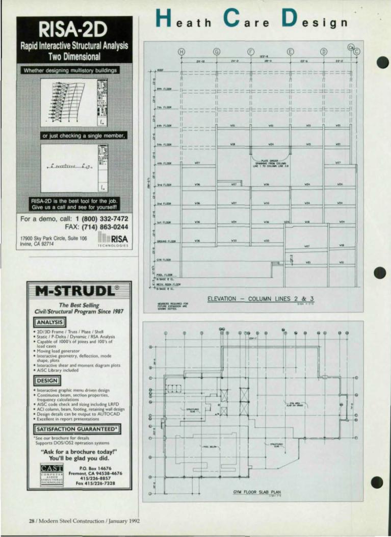
Large Vierendeel
trusses were used to meet
unusual program
requirements in an addition to an acute care
and rehab center in Atlanta
By Albert F. Lagerstrom, P.E.
26 1 Modern Steel Construction I January 1992
• Rehab Center Designed For
Growth H osPitals don't usually in
elude swimming pools and basketball courts, but both of these were required for an addition to the Shepherd Spinal Center in Atlanta, an acute care and rehabilitative facility. When completed in April, the 175,OOO-sq.-ft. structure will include patient floors, transitional living areas, outpatient services, and an auditorium, in addition to the aforementioned athletic facilities.
The steel-framed building is Lshaped, with the west wing ground floor approximately one level below the east wing ground floor, and the two wings are separated with a retaining wall. The combined wings contain approximately 28,000 sq. ft. The stmctural system is designed to accommodate 11 staries in the west wing and 10 in the east wing, with three of the west wing floors and five of the east wing floors are planned as future additions.
One of the challenges on the project was designing several elearspans that were needed to meet the center's program. C1earspans of 75' were required on the ground floor of both the east and west wings to accommodate the gymnasium and the swimming pool, respectively. Standard trusses were considered for spanning the two floors, but this was rejected due to the need to maintain a constant 13' f1oor-ta-f1oor distance. This was necessary because the new building was to be connected to the existiJ1g building with a
three-story bridge, and the bridge floors had to be level to accommodate wheelchair traffic. As a result, the structural depth was limited and neither collection girders or trusses were feasible. Instead, the north-south building frames crossing the pool and gym were designed as multi-level Vierendeel trusses.
Another elearspan area is for the mechanical floor above an audito-rium on the fifth level of the west • wing. The span in this case is 71' and was accomplished with plate girders. One end of each of the two plate girders is supported by a col-umn that extends to the founda-tion. The other end frames into a column that is part of a Vierendeel frame and does not reach the ground. Each girder supports approximately 1,200 sq. ft. of mechan-ical floor and two intermediate col-umns located at its third points, which are designed to carry three patient floors and the roof.
Due to sight line restrictions from the auditorium projection booth, the girder depth was limited to 5'-11 ". A 5' x 2' web opening was required at the mid-span of each girder for mechanical penetrations. the section was built up using 2\12" x 22" flange plates and a 1,.2" x 66" web plate, stiffened as required.
Since several h,tt,re floors are planned, it was necessary to design the frames for both the immediate stresses plus thos that will be im- • posed by the future floors. The stresses were calculated using the CSTRAAD program from ECOM

';t\
" >oj
•
•
•
•
to analyze first the initial frame fully loaded and then the entire frame with only the future floors loaded. A computer program was then written to access member loads from the frame program outputs and combine them for design. In-house design programs were then employed to determine slenderness ratios and member sizes for both beams and columns.
In both wings, the Vierendeel frames are three bays wide. One advantage of this design is that the beams in the center bay are significantly smaller than those required for the outside bays. This allowed space for mechanical ductwork and piping trunks that could serve branches to the outside bays.
The floor slabs are composite metal deck and concrete with a total depth of 41,2" supported by composite filler beams.
Moment Connections Very large moments were in
duced in the frame beams and columns. The beam-to-column connections are full penetration flange welds with bolted web connections.
Very thick sti{{eners were required and the fillet welds needed to transfer sti{{ener loads into the column webs were often at least twice the size of the stiffener, in which case groove welds the thickness of the sti{{ener were used. In many cases doubler plates were required in the column webs. To facilitate design, a computer program was developed to extract loads from the analysis output and design the joints, including stiffeners, doubler plates, all required welds and bolts, and clip angles for the beam web connections.
Several of the frame beams and columns are Group 4 and 5 shapes. The current AISC Specification For Structural Steel Buildings-Allowable Stress Design And Plastic Design requires that back-up bars and weld tabs be removed from tellsioll splices made using Group 4 and 5 shapes.
A question arose as to whether
Hospital additio"s areo/ten difficult dill' to the ex;stcuce of otlrer buildings thallimil site access. Shown at left 01/ tile bottom is a connectlOtI with stiff"lfrs at tilt' j"tersection of a collectiotl gIrder mId co/u",n . Note till! holes ;', the beam and girder {la/Iges to allow ml'cha"ical and electrical penet rat ;o"s .
Modern Sled ConstructIon I Jalluar f 1992 / 27
or Just checkmg a single member, i'i':'''''''''':',
(tra1nrl r f.i-.
For a demo, call : 1 (800) 332-7472 FAX: (714) 863-0244
RISA 17900 Sky Park Cwc1e, SUlI' 106 Irvme, CA 92714 IIC HH OlOGl l S
The Best Selling Civil/Structural Program Since 1987
II ANALYSIS II • 10/]0 Fnme 1 Trll$l ' Pllte ' Shell • Static I p·oelu I Oynal11k I RSA An11Yl11 • Capable of 1000', of 10000u and 100's of
load caSl:1 • MO'IW'll load lenerator • Interactive leometry. deflection, mode sh~, pion
• Interuuve shear and moment dialram plou • Arsc library Included
II DESIGN II • InteractIve lraphK menu drl'l'efl de~ln • Continuous bem, lectlon propertlel,
frequency cakulatlOl\I • AISC code check and IlllnJ mcludtnJ LRfO • ACI CoMnn, beam, foot"l. ret...,..nl wall design • oeslln deta,1s can be OUtput to AUTOCAO • Excellent In report prelenUtlOl\I
Ii SATISFACTION GUARANTEED' II 'See our brochure for deulll Suworts DOSJOSl operatIOn lynems
"Ask for a brochure today!" You' ll be glad you did.
P.O. 10. 14676 Fremont, CA 94538-4676
415/226--8857 Fo1il4151226-7328
He a t h C are Des E
" II II If-- - - -::It:''--==:::lt::- - --"1" I - II II I I II II I
9 n
I t:_ I I
_.1 I II II - - r - --~r----~r=----~~ - ~I:: ojl
Ir ----II - II II I. II \I I - II - - -.~ --I~ - --II
~-II - W' -It" -II I I
w, --- --~'.CIIWIIIoINU
.- ~ w, ~ I -
.- ~ w, ~ ,~
--I-~ - ~ -.-~ ~ ~
- w,
.- - -- -s ::E--! n.:"CL.;::'" --- ---
ELEVAn ON - COLUMN LINES 2 & 3 --~ '" -----
I r , ., ~ +
f ~
o.
IT ~"''III.
+ r llit, I ~ I ~,
II II II II -
I -_w,
-
t
+
W '
... ... -
--.-.-
'I •
., .. . .,
28 1 Modern Steel Construction 1 January 1992
•
•
•

, .>
•
•
•
or not this requirement applies to the welded connection of the tension flange of beams-to-columns. After discussion with AISC staff, it was determined that it does. When the full penetration weld is made the top of the back-up bar is fused into the weld and therefore becomes part of the connection, ac- I cording to the AlSC. The back-up ba r, however, is only tack welded I to the column flange so the connection has a bu il t-in discontinuity. It I is thought that this crack can propagate up through the weld causing failure.
The column splices were detailed for bolted web connections With the flanges welded using double groove welds. The erector requested a substitution of single bevel welds in order to eliminate the need for back gouging. Several
DESCON DESIGNS AND DETAILS STEEL CONNECTIONS
1'1, r' j.:m:<lj "\1
hl\1f\-lIlt-:::-· .--.... -... --'. + ~c
'-.
"-,
c
FOR A FREE DEMO DISK CAll OR WRITE TO
connections were made this way, OMNITECH ASSOCIATES but the additional weld metal re- P.O. BOX 7581 quired proved more costly than
ECOM SESTM Structural Expert Series
+ Written by Practicing Engineers
+ Over 1,800 Installations + 18 Years Experience
2D and 3D Frame Analysis Steel Beam/Column Design
Composite Steel Design Concrete Design Now available on UNIX for Sun and IBM RS/6000
For a FREE DOS Demo se call 414-365-2100
ECOM Associates, Inc. 8324 N. Steven Rd. Milwaukee, WI 53223 back gouging and the erector re- BERKELEY, CA 94707
verted to the double V. It also was I ~===~(=51=0~)=6=5=8=-8=3=2~8===~~~~~~~~~~~~~~" necc sary to remove back-up bars I-from many of the single bevel welds. Steel erector on the project was AISC-member Williams Enterprises, Inc., Smyrna, GA, and fabricator was AlSC-member Steel, Inc., Scottdale, GA.
During the construction period it was necessary to provide temporary columns from the bottom of the discontinuous Vierendeel columns to temporary footings that remained in place until the frames were fully welded . "Camber" was introduced into the frames to offset the deflection anticipated upon removal of the temporary columns. This was achieved by holding the center beam level but slightly higher than the exterior ends of the exterior beams at each floor level. The exterior beams then slop upward toward the center beam. The measured deflections after removal of the temporary columns were slightly less than the calculated values and there is no bounce or vibration in the floors.
The foundations for the building also required a complex design. Rock under the east wing was above the bottom of the foundation
o YB, PIe_wnd nw '-R[[ MICROS"ACttS2410",,~ rNl<l'""k"ftd hudhn.a) K:W. .. .,. ... USA .... c-,w.-.I) . .... MoWdrIll. 1M)
COM'ANY ______ _
OM.-&UCAlm DVM IJ(1 OATI __ 0 CUte" lNClCI5£D
OAn
Mndt'rn Swd onstrucflon I Jililuarv 1992 / 29

H ealth C are Des 9 n
level and required blasting. This rock was the top of an un
derground hill with sharply sloping sides. Drilled piers were therefore required to reach rock und er the west wing, despite the ground slab elevation being 11 ' lower in this wi ng.
Further, the entire area had been used as a landfill for many years so the soil was of very poor quali ty. A basement wa ll retaining outside ea rth varying in height from 30' to 40' encloses the basement levels along the west and north sides of the building. Because of the poor soil quali ty, tie-backs were not feasible, so the walls were designed as cantilevers. The close proximity of a parking deck to the est wall required that the south end wall footing be supported on drilled piers.
Steel Vs. Concrete During preliminary planning,
concrete framing was considered as an a lternative to structural steel.
However, due to the required c1earspans, post-tenSioning would have been necessary. But beca use add itional floors were planned in a future vertica l expansion, post-tensioning was considered und esirable. Unless each floor was c1ea rspanned, concrete construction would have required staged post-tensioning, which would cause a disturbance in the faci li ty when the later floors were added.
C1earspanning each west wing floor was not feasible because the fifth level aud itorium had to be c1ea rspanned in the east-west d irection such that the column at One end of the girder would not reach the ground , which would require a huge collection girder at the lowest level, fo r which insufficient space existed between the floor and ceiling below.
Of course, the column could have been eliminated in favor of a north-south g irder spanning to columns that do reach the foundation,
but this would have crea ted a si tu ation where a girder spanning 77' would support two girders, each spa nning 71' and carrying a mechanica l floor wi th a live load of 150 psf and a vibration and noise isolation floor weighing 50 ps f. Further, the column sizes required to resist the loads and moments imposed by such heavily IO<lded girders were larger than could be tolerated by the architectural layout.
General contractor fo r foundation was Barge/ Wagener & Co., Atlanta, and for the superstructure it was Holder Construction Co., also of Atlanta. Architect on the project was Henry Howard Smith, AlA, Atlanta, GA.
Albert F. Lagerstrolll , P.E., is a pril/cipal with Lagerstrolll & Associates, a cOl/sli ltillg alld structll ra l ellgilIeerillg finll headqllartered ill Oecatllr, GA . •
SOFTDESK Meeting the Challenge ...
of Civil and Structural Engineers.
Offering the most comprehensive, integrated software solutions that run
inside the AEC industry standard AutoCA[)'Il
m SOFTDESK APPl.ICA 1'1ON SOFTWARE FOR Al,. 'TODE5K
1liborty Hall Rood Henniker. NH 01242 USA
603/428-3199 FAX 603/4Z8-1901
ACADO ........................... .. .............................. u.,...... .... , ....... c-. .. ~_
•

.:D. :D ,...
J ,.oJ
•
•
CALL FOR PAPERS 1993
National Steel Construction Conference Orlando Convention Center, Orlando, Fl
March 17- 19, 1993 Pnmary Author:
Name (First)
( )AISC Active Member (Middle Initial)
)AISC Associate Member (Last) (Professional Suffix-Degree)
)AISC Professional Member ( )Non-Member
PositionfTitie
Place of Employment
City
Business Phone
Home Address
CIty
Home Phone
Co·Author(s):
t . Name
2. Name
3. Name
(First)
(First)
(hrst)
(Middle Inmal)
(Middle Initial)
7Middle fnitTaQ
State Zip
Ext.
State Zip
'Preferred mailing address ( )Business ( )Home
- (Last)
(Last)
(Last)
(Professional SuffIX-Degree)
(ProfessIOnal Suffix·Degree)
(Prolessional Suffix·Degree)
Invitation/Call For Papers The t 993 National Steel Construc·
tion Conference will be held at the Orlando Convention Center. March 17-t 9, 1993. Participants Include structural engineers, fabricators, erectors. educators. and research· ers. PotentIal authors may submit abstracts of papers on deSIgn, fabri· cation and erectIon of steel struc· tures for buildIngs and bridges. Topics of interest include:
Practical application of research ; Advances in steel bridge design and construction; Composite members and frames ; Buildings designed by LRFD; Heavy framing connections; Steel· framed high·rise residential bUIldings; Partially restrained connections and frames: Economical fabrication and
erection practice; Quality assurance and control; Case studies of unique projects; Computer·aided deSign and detailing; Case studIes of unique projects ; Computer-aided design and detailing; Material considerations; Fire Protection; Coatings and material preparation; Structural systems.
Guidelines for Abstract Proposals
Abstracts for papers must be sub· mined before June 15, 1992. They should be approximately 250 words in length, and submined on a separate sfleet of 8 t /2" x 1 t " white paper anached to this form .
Authors will be informed of the Or· ganizing Comminee's decisions by September t, 1992. Successful au· thors must submIt the" final manu· scripts for J)ublication In the 1993 Conference ProceedIngs by Decem· ber 15.
Preparation of Paper Final manuscripts for publicatIon In
the official t 993 Conference Pro· ceedings are expected to be approxi· mately 20 pages in length. Copy (including photographs) must be camera·ready. Complete instructions will be forwarded to authors upon ac· ceptance of Abstract Proposals.
Poster Session Papers not accepted for presenta·
tion at the Conference may, at the author's expense, be presented at the Conference Poster Session. Guidelines for the Poster Session will be prOVIded upon request.
Return your abstract with this submission form before June t 5, 1992 to: American Institute of Steel Construction, Inc., One East Wacker Drive, Suite 3100
Chicago, IL 60601 -2001 Attention: 1993 NSCC Abstracts Phone 3121670-5400 Fax: 3121670-5403

H ealth C are D es 9 n
Site restrictions, a
fast-track schedule and the need for flexibility all
helped steer the project to a
steel solution
By Frederick M. Gibson and James F. Stewart, P.E.
32 1 Modern Steel Construction I January 1992
Tight Site Complicates Construction
S urrounded by existing hospital buildings and with limited street access, the site for the new 462,OOO-sq.-ft., 24-story Ellison Building at Massachusetts General Hospital presented a unique challenge to the design team.
In 1982, Massachusetts General Hospital began developing a master plan to modernize its entire 1,080-bed inpatient facility. After detailed analysis, it was determined that two existing buildings, housing approximately 400 beds, would be retained and renovated. The remalllll1g five structures would either be demolished or rehabilitated for other uses. After reviewing the master plan alternatives, the hospital opted to construct a new three-phase 580-bed inpatient facility adjacent to the existing inpatient core structures, with the $105 million first phase being the 441-bed Ellison Building.
Site Challenges In addition to limited street ac
cess through a narrow 14'-high archway in an existing building, the new building was to sit on filled land reclaimed from the Charles River. Because the 3urrounding structures were supported on wood piles, it was necessary to ensure that the groundwater level was not depressed during the construction of the new tower. Therefore, the excavation and foundation construction was performed within a steel sheet piling enclosure, which was driven into impervious glacial till or silty clay soils. A groundwater recharge system was installed around the ex-
cavation perimeter where groundwater levels were monitored relative to the wood pile foundations.
Another challenge was the minimal space available for the new tower's footprint, which was limited in size by the surrounding existing buildings. The tightness of the site required that cornices on two adjacent buildings be temporarily removed during construction in order to permit the erection of the new tower's curtainwal!.
Alternative Structural Systems
Because of the lengthy review and approval processes involved in health care construction, the hospital wanted a design that cou ld be constructed as fast as possible. However, the lengthy approval process--<:ombined with the 10-year phased construction period-meant that the building's structural system also had to be readily adaptable to change. Flexibility also was important during the life of the structure since medical technology is constantly changing, and it was essentia l that the building be designed to house functions that could not be anticipated during the design phase.
To speed up the project, a fasttrack schedule was adopted, which permitted the demolition, excavation, and subsurface work to begin while construction documents for the superstructure were being prepared. Likewise, the interior fit-up documents were prepared while the substructure and superstructure were being erected.
Initially, both steel and concrete
•
•
•

•
•
•
structura l systems were considered . A structural steel frame was selected based on its lower cost, its ability to meet a fast-track schedule, and its inherent fl exibility.
Lateral Loads Building lateral resistance is
provided by a moment frame using 27"-deep wide flange column sections spaced 26' on center to accommodate a patient room layout uninterrupted by columns. Columns were all A572 Grade 50 steel. A more economical centrally braced core was not feas ible due to the required loca tion of elevator banks.
The fl oor system consists of 2"and 3"-deep composite metal decks with light-weight concrete fill and composite beams and girders spanning up to 34'. Both A572 Grade 50 and A36 steel were used, both for economy and to meet serviceability requirements. Shored construction was specified to allow the use of shallower sections under the constraint of matching floor elevations with exis ting adjacent buildings, which were approximately 12' floor-to-fl oor.
Steel fa brica tor fo r the 4,300-ton project was AlSC-member Owen Steel Co., Inc. Because of the site constraints, offsite receiving, staging and marshalling areas were used for all of the structural steel.
The unusual, triangular shape of the new building, as well as the varied programmed spaces demanded in a hospital, presented additional challenges. While the triangula r shape provided an efficient floor configuration for hospital services, und er certain wind conditions it had a tend ency to uplift at the comers. The problem was resolved by anchoring each column with six 2V4"-diameter by 5'-6"-long high-strength bolts, as well as rein forcing the drilled pier for tension and anchorage into bedrock.
Due to the fill deposits overlying the si te, a deep foundation system was required to extend 40' to 90' below the foundation level to bear on shale-like bedrock depos-
TI,erIOS/! proximilv of I/Ie adJace"t blllldmgs i" ti,e hospital campier grcnlly complicated ti,e construction of the IIi"W 24-story £Ilisoll Bllildillg at Mnssncll/lsetts Gellernl Hospilnl.
Pllolo lop riglll by Mldm,1 Krigmnll Pllologrnplly.
Lefl 1'"010 by WI.ed er Photograph,cs.
Modern SIl"{'l onstrucllon I January 1992 / 33

H ealth c
. --, ."" .... 1 ,P'O",L Ll!YIL
The triall8111ar con/iguratioll of the tower portion of tile structure was selected to provide all efficient floor configuration for hospital services. Also, ti,e new building was designed wI,h similar floor·to-fIoor heights as an adjacent structure, which permitted the coflStructioll of cOIlllfeting bridges.
The A ll New
are D esign
its. The bedrock surface slopes relatively steeply across the si te from northeast to the southwest.
Although precast concrete piles would have provided the most economica l foundation system, drilled piers were selected in consideration of the effect of noise and vibration levels on sensitive hospita l procedures and patients. A typical pier consists of an 8' -diameter reinforced concrete shaft belled into bedrock. An 18"-thick structural slab, designed for a 20' hydrostatic head, caps the drilled pier and completes the foundation system.
Improved Efficiency Throughout construction, it was
essential that the hospital complex remain in full operation. Although the critica l bridge linking new and existing facilities is part of the second phase, its construction was timed to coincide with the first phase to facilitate patient movement during the rest of the second
phase. Fore operating economies and
access, it was essential that the new structure match the existing building floor elevations, which were approximately 12' floor-to-floor. Integrating the old with the new facilitated internal movement and helped to reduce operating costs. In addition, the matching floor elevations allowed, in many cases, four inpatient units to share support facilities, which allowed the hospital to avoid duplication of services.
The 26' -wide by 34' long bay was selected to maximize alternatives for patient room configurations, which ranged from intensive care cubicles to the project's standard private/semi-private convertible patient room.
The larger-than-standard bay length allowed planning flexibility for specialized requirements in certain services, such as offset corridor alignments for increased visibility
""_"'~\O"""'''''_'_' '''''' ' '' '' "''' .. 110 . .... . . _ ... •• ..
, '~J ,. '5 JOBB ER III " . ,. , . " _ ... , .. i B B @"il:" • 1IIiii. Iii . 8888 •••• =II1II
Jobber III The BEST & Fastest Feet! Inch/ Sixteenths Engineering Calcula tor with easy Decima l & Millimeter Conversion
. 0[!!] ••• 1II1i1 •••
. 00 ••• El8 ....
Actual size 3 114' x 5 112' x 318' The only Calculator with the revolutionary Jobber III Patented OIlS Keyboard that can reduce entry errors up to 50 % and cut calculating time by 200 %.
The All New Jobber III Dimensional Calculator Features: ". Quickly Add, Subtract, Multiply, & Divide feet, inches & sixteenths! ". Easy to use Trig functions with fast solutions to right or oblique triangles & circles without
complicated charts or tables a utomaticall v in a ll modes! ". Solve right triangle Bevel-Slope-Rise & Runs instantly for diagonals,stringers , & rafters ! ". Powerful 8 Bit Processor with 4 Memories (Memories retained even with power off) ". I OOO's Sold to Detailers , Engineers, Dr'dftsmen, Architects & Layout men!
•
•
Reg. Price Special Order Toll Free • $129.95 $99.95+$3.ooS&H 1-800-635-1339
34 1 Modern Steel Construction I January 1992

in intensive care and pediatric inpatient units. An additional benefit is that the corridor wall of the patient rooms does not stradd le column and beam locations, which yielded improved access from above the ceiling for ductwork and plumbing.
Creating a design that would allow for changes while the structure was under construction reoqu ired close cooperation between the hospital, architect Hoskins Scott Taylor & Partners, Boston, general contractor Walsh Brother, Inc., Cambridge, MA, and structural engineer McNamara & Sylvia, Boston.
Frederick M. Gibsoll is an associate partner with Hoskins Scott Taylor & Partners, all architectural, plallning alld illterior design firm with offices ill BostOIl and Minneapolis. James F. Stewart , P.E., is with McNamarn & Salvia, Structural Engineers, Bostoll .•
The project lOOS fast-tracked a"d interior fit-u" docume"ls were prepared while the substructure and superstructure were beitlg erected.
+ + + + Individually, SDS/2 software modules are leading edge technology.
Together, they add up to the only fully integrated steel fabrication system available anywhere. Start with a single module or more. SDS/2 is the one system that can grow with your future needs.
Engineering, Analysis and Design Module
Estimating Module
DE8l'4~DIIIIII "Flrsl ln ... SoHware, Se .. ic., Solutions"
Production Control Module
Call today ... 800·443·0782 402·478·8Z78
l , . ~
;. 'j
.. / . ..t:lI! 1'"" -..:
, . CNC Interface
Module
Modern Steel onstruchon I January 1992 / 35

Don/tGa t Caught In The Mo-......... When introdu ed to the draft in world, many peop le j u m on the CAD wagon. What detai l ing profess ional found was that, w hile your sheets looked g reat and correction t ime d ropped, tota l t ime was about the same, or lo nger, than using a penc il. G raphic oriented deta ili ng software i the process a little, but correct ions and mod i f ica tions were a nigh tmare.
It 's 8 to 1 0 tiftles, manua l d e ta iling, 3 to 4 times fas ter graphic ba sed sys Corrections and modifications are a sn and the flexibility is astounding.
•
With STEELCAD you don't have to you just have to 1 -800-456-7875
•
•

•
•
•
Software For Fabricators And Detailers Hess Technical
Services
Cmmeet is a productivity-boosting package for structural steel
detailing calculations used by structural engineers and detailers. It essentially designs all of the connections covered in the AISC M""lIal of Sleel COllslrllclioll ( inth Edition), including framed beam connections, seated beam connections, eccentric connections, connections in tension, and moment connections. It also includes single plate connections and a wind moment connection, both from the AJSC Mallllal of Sleel COllslruclioll, a program for connecting angle welds under combined shear and axial load, and triangulation. Version 3.5 consists of 25 programs and an extensive data base.
Connect ensures consistent calculations and complete, permanent documentation. It includes a complete file handling and annotation utility. The menu-driven program is self explanatory and guides the user step-by-step. User friendly features include a HELP key avai lable at all times and an automatic default feature. An error-trapping feature also is included .
The software runs on IBM compatible computers. While not essential , a hard drive is strongly recommended .
For more information, contact: Hess Technical Services, 2389 Millgrove Road, Pittsburgh, PA 15241 (412) 831 -2010.
Softdesk
A ll Softdesk (formerly DCA Software) Structural products are
integrated, modular and run inside AutoCAD. Packages include: The Modeler, which allows the creation of a complete 3D model inside AutoCAD; Plalls & EIl'lX!tiolls draws all types of structures in plan, section, elevation or 3D; Details & Secliolls creates accurate construction details; and Sleel Detailer provides the tools to create shop fabrications, erection and bolt setting draWings.
The Sleel Detailer couples structural information with parametric programs to quickly produce accurate high-quality draWings. Operating interactively within AutoCAD, the detailing system provides the user total control over drawing production. Sophisticated reporting fea-
tures automate the preparation of project material summaries. The price of the module is $2,995.
For more information, contact: Softdesk,7 Liberty Hill Road, Henniker, NH 03242 (603) 428-3199.
SSDCP
A n updated package of programs for making Strllcillral
alld Miscellalleolls Steel Shop Drawillgs has been introduced by SSDCP. Improvements in this latest release give the designer more flexibility . At the present time, SSDCP has more than 93 different parametric LISP programs that will run inside AutoCAD Release 10 or 11.
Because the programs run inside AutoCAD, the drawing is made as you watch the monitor. Any modification or change can be easily made using any of their sub-programs or any standard AutoCAD command you choose before the drawing is plotted . Prices vary depending on number of programs ordered .
For more information, contact: SSDCP, 110 Shady Oak Circle, Florence, MS 39073 (601) 845-2146.
Structural Analysis, Inc.
A powerful new package of programs assembled for steel fab
ricators is available from SAl. The Steel Fabricator consists of 41 pm· grams from SA l's library of steel design, structural analysis and graphiCS software developed during the past 25 years. Programs are included for the deSign, detailing and analysis of beams, columns, trusses, basepla tes and footings. This huge package is being offered at an introductory price of $395 (less than $10 per program). Several free sample programs may be obtained for a small material and handling charge of $19.
The package is production oriented . It's very easy to use and gives fast, accurate design results. A menu with spreadsheet formats and onscreen help features simplifies usc. A built-in text editor and error checking also is included . Input always is saved for reruns or future use. GraphiCS programs allow the user to check input and view results. Standard steel shapes are stored within the program or on disk files for fast easy access.
The software runs on IBM-com-
patible computers. For more information, contact:
Structural Analysis, Inc., 555 South Federal Highway, Suite 210, Boea Raton, FL 33432 (407) 394-4275.
AutoSD
T wo of the strengths of a complete detailing pack.1ge from
AutoSD me its handling of gusset plates and stairs.
The gusset plate program c.1n be used to calculate everything involved in the gusset plate. It can be used not only to derive dimensions for detailing, but can also check dimensions of an existing detail by inputting the dimension from the work point to the first hole. If that dimension works it will be used, if it does not, the correct dimension will be calculated and used instead. The checker will be prompted if a design problem occurs. There are six different types of gusset plates to choose from and each has many available options, making it very easy to customize. After the calculations are made, the plate is drawing on-screen to scale in whatever orientation is selected.
The stair program offers four bottom conditions and two top conditions, pan treads, bolted treads or individually designed pan treads. The stair is drawn to scale with bevel sloping up to either the right or left.
For more information, contact: AutoSD, Inc., 4033 59th Place, Meridian, MS 39307 (601) 483-0601
Steel Solutions
A complete managerial software package for steel fabricato rs
and service centers is available from Steel Solutions, Inc. Included in its STEEL 2000 product line is an Interactive Estimating system that costs labor instantaneously as a bid is being input and a Material Management program that includes multing, nesting of plates, ordering of material and inventory control. The shop is managed with the Production
ontrol module that in ludt"S bill of material, cut lists, production status and CN interfaces. The Plate Block
esting and Tn.e Profile Nesting programs insure the fabricator that the most economical method of cutting plates from stock and remnant sizes is achieved .
Through the use of a fourth gener-
Modern Steel Construction I J .. mu.Jry 1992 / 37

ation data base manager, STEEL 2000 has become a leader in open architecture design. All of the data base files and reports are available to the user for his own manipulation and ad hoc reporting. The program was developed in conjunction with Steel Solutions sister-company, Steel Service Corp., a large Southern fabricator and service center.
For more information, contact: Steel Solutions, Inc., P.O. Box 1128, Jackson, MS 39215 (601) 932-2760.
Romac Computer Services
A series of progTa ms to assist teel fabricators with their ma
terial management requirements is available from Romac Computer Services. These programs include Pmduction Control with Bill of Material. Inventory Control. Purchasing, Length Nesting, and Plate esling. Each module can be purchased and implemented individually or can be integrated with the other modules. Additionally, modules are available to transfer data between Romac ap-
plications and selected third party applications such as detailing and accounting.
The software offers an economkal solution to computerization of material management with individual modules starting at $295.
For more information, contact: Roger McCarter, Romac omputers Services, Inc., 332 South Main St., P.O. Box 660, L.1ke ity, TN 37769 (615) 426-9634.
Computer Detailing Corp.
Beams aud Columlls, a program for creating fabrication drawings
for structural steel and miscellaneous metal. uses AutoCAD to create a detailing environment and therefore is extremely versatile. Anything that can be fabricated in a structural shop can be detailed with this system. The program can be configured to produce details with a variety of different shop standards, including Bills of Material. The system follows the same procedures that an experienced person uses when producing details
manually, and therefore is very easy to learn.
Because of its versatility, it can be used very effectively on small jobs with a varietr or structural elements and by smal drafting companies. It is not necessary to lea rn a complicated input system or to have extensive training in computer aided drafting. Details with spandrels, moment connections l fittings and other trades can be easily handled. Other programs for detailing stairs and creating plans a nd elevations are ava ilable. All routines and programs are in tegrated allowing information, job and company standards to be established one time for use on a ll subsequent drawings, without reentering data .
For more information, contact: Computer Detailing Corp., 1310 Industrial Blvd ., Southampton, pA 18966 (215) 355-6003.
E.J.E. Industries
V ersion 4.0 of E.J.E. Industries' Structural Material Sorter is now
ava ilable. The Novell Network o r MS-DOS compatible system is de-
•
Structural Material Sorter Ver. 3.0 -1-, AutoSD Steel Detailing •
A series of programs
designed to help
steef fabricators
manage material.
::-.-~--
'--"-'-_._._--1_ ";1 -;: __ ".:J
. --.;. .. -"--'-. - .. " -. ------ . .. ..:.:..~
_-·cU __ ;:,,;,:..l!
-.---
• Reduces labor - Increases accuracy. • Automatically computes weights, surface
areas, bolt counts and lineal totals. • Quickly sorts lists Into proper order. • Produces optimum length-cutting lists from
in-house stock, vendor's stock or the best combination of each.
• Provides shipping lists based on piecemark sequence.
• Tallies material costs, shop hours and field hours for easy estimating.
• Uses simplif ied terms so non-tech personnel can operate with ease.
• External Data Interface can import existing computer-based material lists.
• Call today for a FREE demo kit, including the tull system's operator's manual!
E.J.E. INDUSTRIES. INC.
CO MPUTER SOF T WAR E FOR STEEL PROFESSIONALS 287 Dewey Avenue Washington, PA 15301 (800) 321-3955
38 / Modern Steel Construction I January 1992
At last, the sensible detai ling program written by detai lers for detailers. Menu driven means easy to use. Supported by numerous graphics means easy to learn. See what you arc drawing as you draw it. 1 You stay in control.
Deta il beams, columns, braces, gusset plates, stai rs, stair rails. I
Automated Steel Detailing works with AutoCAD® release 9.0 or later.
$3500,00
Calculator Programs Calculate gusset plates, end I
connections, tearout, camber axis1 I connections, oblique & right triangles. circles, and 8 Ft-inch I calculator that emulates a n HP® and more. For DOS 3.0 and higher with EGA or better.
$250.00
For more infonnation write: AutoSD, Inc. 403359PL Meridian, MS 39307 (601) 693-4729 ~.

•
•
•
signed to aid steel fabricators and detailers in managing material lists. It reduces the man-hours required to process the lists by requiring the operator only to enter the material items and then automatically providing weights, surface areas, bolt counts, shipping lists, estimating reports and optimum cut lists. In addition to processing jobs, it also keeps the company's in-house inventory, which allows an inventory-dollar figure to be provided for accounting purposes. It also allows the nesting Module to utilize inventory lengths and add back any useful remnants (drops) that remain after cutting.
The program produces extremely efficient count lists by running thousands of combinations on the lengths, as opposed to other techniques that use a simple placementalgorithm that does not yield a truly optimum cut. In terms of operating fleXibility, the system can accept dimensions in feet and inches, inches, or millimeters, which eliminates the need for cumbersome conversions during entry.
For more information or a free demo kit, contact: E.).E. Industries,
Inc., 287 Dewey Ave., Washington, PA 15301 (BOO) 321-3955.
Structural Software
FabriCAD Six, a detailing program from Structural Software, fea
tures a new graphical input that simplifies the interaction between user and computer. Everything that goes into a job is centralized under one menu option. All attachments, base and cap plates, moment plates, splice plates, skewed beams, etc., are entered directly through the graphical E-plan. A new mOllse-driven menu further simplifies selections. 0 detailed setup work is required because rid lines are unlimited and can be added, inserted, adjusted or deleted at any time. The unique member placement feature allows the user to re-process a job as many times as he likes without having to worry about re-plotting all of the sheets.
The company also offers an Estimating program that comes prelo.:,ded with information based on real-world industry averages and offers several pricing databases that can ultimately reflect the actual cost
of labor at YOllr shop. It keeps track of current discounts, base prices, cambering and force milling extras from U.S. Steel and Bethlehem Steel, as well as length, grade, size and quantity extras. Schedules for additional mill suppliers can be set up as needed. Plus, the program mults the material before it is priced so that the estimate reflects any waste encountered on a job.
For more information, contact: Structural Software Co., 5012 Plantation Road .E., 1'.0. Box 19220, Roanoke, VA 24019-1022 (703) 362-9118.
Silver Collar Systems
P rOFAST from Si lver Collar Systems is a fully automatic (no
point and shoot), fast-track detailing system designed to remain in production should the operator leave. Easy input plus on-screen manual combine with automatic framjng and sheet handling to make the system easy to learn and to use. With a few days of training, each dctailer can generate a minimum of 10-12 full sheets per day of straight, sloped or skewed framing plus nips and vall-
Detailing of the future is now available.
Procedural Detailing Systems The true test of any automated system is not the detailing of merely columns and beams, it is its ability to address the complex, highly detailed engineering requirements of such things as stairs and ladders.
Only Dogwood Technologies offers the solution to these complexities.
Dogwood Technologies, Inc.
Innovative Structural Steel Detailing Systems
Call or Write Today_._ .. P_O_ Box 52831· Knoxville, TN 37950-9928·800-346-0706
Modern Steel Construction 1 January 1992/39

skewed framing plus hips and vallies. A comprehensive connection design analysis and printout also can be produced.
All column and beam details have the needed section cuts. All sections and details are drawn clearly and, where required, are exaggerated for shop readability. The data entry system allows the detailer to setup connection standards and then interact, as needed, to control the final connection configuration. The main software module, which is written entirely in "C", costs $4,995.
For more information, call Silver Collar Systems at (214) 699-1994.
NES, Inc.
PODGE is an integrated system of modules designed to perform
both complicated and common geometric calculations with both speed and simplicity. II performs calculations on bracing, circles, roof elevations, oblique triangles, skewed plates, sloping beams and stairs. Also includes an AISC file.
Contact: Northridge Engineering Software, P.O. Box 2014, EI Segundo,
CA 90245 (BOO) 637-1677.
Dogwood Technologies
D ogwood Technologies offers two Procedural Detaili"g Systems
to provide realistic solutions to the problems faced by steel detailers and fabrication engineerin~ departments. Both PDS and PDS LIte were developed to detail a wide variety of structural members through the use of text input , allowing greater productivity than most graphics packages. In those rare instances where a member cannot be described with text, it may be detailed with interactive graphics, an integral part of the system.
Dogwood Technologies has augmented the versatility of the U IXbased system with interfaces to other engineering analysis and graphics packages, permitting downloading of design drawings and optional interference checks. The systems are deSigned to allow the uninterrupted now of information from de!.li1er to fabricator and have the capability for the exchange of infonnation between the project control manager, accounting functions and warehouse facili-
ties. Turnkey configurations are con
figured to a customers' needs. Configurations range from Single-user PC-compatible systems to multi-user systems with more than 25 workstations.
For more information, contact: Dogwood Technologies, Inc., P.O. Box 52831, Knoxville, TN 37950-9928 (BOO) 346-0706.
Design Data
A new enhancement for the SDS/2 Illtegrated Steel Fabrica
tio" Computer System from Design Data, which will allow the program to run on the Hewlett Packard U IX system, promises revolutionary speed and nexibility. SDS/2 offers independent but fully-integrated modules for Estimating, Detailing, Production Control, and CNC Interface, allowing a shop to build their computer system as they grow into it, both technically and financially. HP-U IX's nexibility is made possible by its increased processing speed and the use of multiple "x-windows" that allow the computer to
!ifi= BEAM DETAILS In minutes STEEL using "BEAMS & COLUMNS" INDUSTRY
*'8 • l' • \4'-8.:'- -- ~ SOFTWARE with AutoCAD
;h~; . r -.'i . "-1 ~1, ·111 ..... t .... It ~, ~ .. " ... , 00' \ i!;! . ~ ~1 • Structural Steel Estimating (,
t..- 'I _ ..
("""" i'-ir I - f~ • Structural Steel Advance
~
-1"] i-O 1 <'L Bill of Material ~ 1- -
_ .... <'i' f- -i- S ~
• Inventory Control ~
~- 'V-)~ I ' " 4 .. '1)
• Production Control "" r-: ::'t~I'J • , Co " ~r r .
~ ~ • Purchase Order
~ _. • ~ .... • Plate Nesting ;-1 I • Il'~ ,. I . ' ., ; ,
I~ COL. c • Length Nesting l.,i ~ I I ~ - ~t ~-l ;'{~ -....
• . \ • Detail Drawing Log
~ }rM • Rebar Processing
> • . " O.THER PROGRAMS AVAILABLE FOR DETAtLtNG
For IBM PC/AT and Compatibles '- 14" a BEAMS. COU·MNS. STAIRS.
PLANS AND ELEVATIONS. BRACINC. CUSSETS. romac CAU /tiO" ! MATERIAL MANA CEMENT
I'or Injbrmohon abow sQ\ltng hfJ'M' wdh productn" 'l1 progTOms from Computer Ser v ices
COMPUTER DETAILING CORPORATION P.o. Box 660 Lake C,ty. TN 37769 1310 Induttrltl Blyd.
Southampton. PA 18988 215-355-8003 I
PH: 615-426-9634 FAX: 615-426-6454
40 I Mod('rn ted Con~truction I january 1992
•

•
•
•
accomplish more tasks at the same time. For example, an SDS/2 user can now process a newly entered job in the Detailing module, print a report in the Production Control module and review data in the Estimating module, all at the same time. HP-
IX is now being used as the regular operating system for all SDS/2 software, and is available to current users through an upgrade.
These modules are designed to work within the existing fabrication standards, instead of making the user conform to the needs of the system. Data is entered once, and then shared by all modules. The 3D Frame Input System allows the user to work in any plane of the structure.
For more information, contact: Doug Evans, Design Data, 1033 "0 " St., Lincoln, NE 68508 (BOO) 443-0782.
Vertex Design Systems
The Vertex Detailer is an AutoCAD application that enables
the user to assemble building details rather than having to draw them using CAD primitives. The program greatly increases productivity, consistency and accuracy. More than 25,000 building "components"product and material drawings-are included, including thousands of structural shapes. Components are organized in CSf divisions and are selected via icon menus. In addition to drawing production, the Detailer automates plot sheet layout and utilizes a database manager for easy look-up of the many components and details. Retail price is $1 ,995.
Also available is the ASC Pacific Electrollic CADalog. One of 18 produced by Vertex, this electronic catalog provides steel roof system information, detail draWings and specifications. These catalogs nm on P s using a Simple, intuitive pulldown menu system and are avaiJable for free to qualified professionals.
For more information, contact: Vertex Design Systems, 282 Second St., 4th Floor, 5.1n Francisco, CA 94105 (415) 957-2799.
Mountain Enterprises
The ME2 system from Mountain Enterprises produces finished
details from erection drawings built with easy on-screen menu choices or by direct, highly efficient entry of individual members (piece-by-piece detailing). Also, a combination of both may be used. The program runs
on IBM-compatible computers and are mouse-based with oil-screen menus for ease of data entry, eliminating coded input forms and most typing. Under development is a Windows version. Currently available is version 3.1, which can run on inexpensive Wyse l Amdek 1280xBOO HiRes monochrome monitors or a variety of SVGA monitors.
The program composes details from connection components premade by Mountain EnterpriSes or by the user with ME2's parametric, steel-specific CAD. While more complicated than simple CAD programs, the system has the advantage of being limited only by the user's capabilities, rather than the programmer's expertise. The detailer can have control over every aspect of the product, including down-loading CNC data and fabrication style. Because a wide variety of connection types are included in the program, the detailer does not have to produce incomplete details and then fix them with a CAD program or by hand .
For more information, contact: Mountain Enterprises, 117 E. German St., P.O. Box 190, Shepherdstown,
DETAIL S I EEL UstKl AUTOCAD OVER 93 DIFfERENT PARAMETRIC
USP PROGRAMS FOR MAKING STEU SHOP DRAII1NGS USING AUTOCAD RUEASE 10 OR 11.
ANCH. BOLT AND ERECTlON PLANS BEAMS AND COLU~NS
HORIZ. &< VERT. BRACING BRACING PLATES
PAN, GRATlNG, CHK'O PL STAIRS STAIR Ie WAlL HANDRAIL
STRAIGHT t.4UL Tl-UNE HANDRAIL TRUSS WORK
SECTlONS THRU AlSC MEMBERS CALCULA TOR INSIDE AUTOCAD
WEUl S'1\4BOLS, AND ~ORE STEEL DETAIUNG PROGRAMS
THA T YOU CAN AFfORD. GET ·All· YOUR PROGRAMS
FROM ONE SOURCE NOT AVAILABLE IN ~ETRIC SYSTE~
CAll FOR ·OEMO· DISK IN USA
SSDCP 110 SHADY OAK CIRCLE FLORENCE, MS. 39073
601-8~5-21-40
WV 25443 (304) 876-2534. f--
Steelcad International
S teelead's range of Alltomated Steel Detailing Software are de
signed to be true production tools for the steel fabrication industry. Where some Automated Detailing products use a CAD-based graphic interface for input, Steelead uses a text-based input, taking "raw" numbers and automatically prodUCing drawing files, gathering them, and then moving them to either a CAD program for display or directly to the plotter. The text-ba ed system allows greater productivity (an 800% increase in total drawing output vs. 250-300% with a graphic system> and more nexibiJity and speed in effecting changes, corrections and alternative proposals.
Steelcad also provides a graphiC input module (Steelcad Ill), allowing automated detailing from erection plans. The information input to Steelcad II I is passed to Steelcad Il for processing and output. The drawing calculations are accessible in report form, with all material collected for individual drawing Bill of Materials (B.O.M.) and complete contract B.O.M. Also, C C files are provided and automatically updated .
For more information, call Ben Galloway at (800) 456-7875.
r----
SAVE TIME AND MONEY CALCULATE CONNECTIONS
with CONNECT · version 3.5 Soflware and Dala Base
for IBM PCs and Compatibles Proven, easy to-use, moderate price
DHAILERS, STRUCTURAL ENGINEERS design, document, check:
Framed Beam Connections Seated Beam Connections
Eccentric Connections Connections in Tension Moment Connections Hip and Valley Details
Oblique braCing with Setbacks Web Stiffeners Triangulation
and more. Print a hard COW of calculations
and/or save on disk. Updated to AISC 9th Ed .
Demo package available.
Write or call today:
Hess Technical Services 2389 Mill Grove Road Pittsburgh. PA 15241
(412) 831 -2010 or (412) 833-7525
Modern Sleel Construction I January 1992 / 41
Advertisers' Index • A
AISC Software .. ..................... .. ..... .. .... ... .................. 19 AutoSD .............. ...... ......... ...... .. .................... ..... .... ... 38
B Bouras, Nicolas j . ........ .................................... .... .. Cll
C CAST ...... .. .......................... ...... ... .... ... ..... .. ................ 28 Chaparra l Steel ......... .. ........... .... ....... .... .. ................. 15 Computer Detailing Corp ................................ .... .40 Computers & Structures Inc. (CSI) ................... CIV
o DCA Software (now Softdesk) ............................. 30 Design Data .. .... .... .. ......................................... .. ...... 35 Dogwood Technologies ...... ..... .... ... .... ...... .... .. .... .. . 39
E ECOM Associates, Inc ... ..................... ....... .... ... .... .. 29 EjE Industries .. ..................................... ....... .. .... ...... 38
H Hess Technical Services ............................ ... ..... .... .41
J jobber Instruments .. ..... .... .... .. .... ..... .. ... .. ..... ........... 34
N National Institute of Steel Detailing .................... 25 National Steel Construction Conference .... .. ... . CIII NSCC Call For 1993 Papers .... .... .... ... ... .. ..... .... ..... . 31
o Optimate .... .. ...... .. ....... ... ..... .. ..... ... .... .............. .. ........ 18 Omnitech Associates ..... ............ .. ..... .. ........... ......... 39
R Research Engineers, Inc .... ... ... .. ...... ..... ... .... .. ....... .... 7 RISA Technologies .... .. ............. ............................... 28 ROMAC. .. .. ...... .. .... ... ..... ... ..... ....... ...... .. ...... .. .... .. .... . .40
42 1 Modern Steel Construchon I January 1992
S SSCDP ... ..... ................................ .. .... .. .... ..... .. ... .. ...... 41 St. Louis Screw & Bolt Co ..... ................................ 14 Softdesk (formerly DCA Software) .... .... ..... .. ... .. . 30 SteeIcad International .. .... .. .................................... 36 Steel Deck Institute ..... .................. ......................... 13 Structural AnalYSiS, Inc. (SAl) .............................. 29 Structural Software Co ....... ..... .. .............................. .3
T TradeARBED Inc .... ... .... .. .. ..... .................................. .5
V VuIcraft ..... ... .................. .............. ............ ... ........ 22-23
For advertising information, contact:
Pattis /3M 7161 North Cicero Lincolnwood, IL 60646 (708) 679-1100 FAX (708) 679-5926
Contact Chris Luke for: Alaska, Arizona, California, Colorado, Hawaii, Idaho, Iowa, Kansas, Montana, Minnesota, Nebraska, Nevada, New Mexico, North Dakota, Oklahoma, Oregon, South Dakota, Utah, Washington, Wyoming, CANADA.
Contact Dan Ramage for: lllinois, Indiana, Michigan, Missouri, Ohio, and all foreign except Canada.
Contact: Marci Lynn Costantino for: Alabama, Arkansas, Connecticut, District of Columbia, Delaware, Florida, Georgia, Kentucky, Louisiana, Maine, Maryland, Massachusetts, Mississippi, New Hampshire, New jersey, New York, North Carolina, Pennsylvania, Rhode Island, South
•
Carolina, Tennessee, Texas, Vermont, Virginia, • West Virginia, and Wisconsin

, - .
•
•
6th Annual
National Steel Construction Conference
Developments in Painting Structural Steel
Practical Solutions for Connection Problems
O'Hare's New International Terminal
High-Rise Steel Frames
Economical Welded Structures
Designing with Tube Steel
Solving the Steel Parking Deck
Dilemma
Building Code Updates
More than 1 00 Exhibitors
Integrating Design, Detailing and Production
Systems
Short Span Steel Bridges
Designing Heat Straightening Repairs
Repairing and Retrofitting
Buildings and Bridges
1992 T.R. Higgins Lecture
Exhibitor Workshops
Improving your shop safety
45 seminars & workshops
And much, much, more!! !
EXHIBIT BOOTHS STILL AVAILABLE
For more information contact: David Wiley, American Institute of Steel Construction, Inc.,
One East Wacker Dr., Suite 3100, Chicago, IL 60601-2001 ; Phone 312/670-5422; FAX 312/670-5403
•


![CSSBI-Steel Roof Deck Floor Deck[1]](https://static.documents.pub/doc/80x56/552e8098550346231a8b49af/cssbi-steel-roof-deck-floor-deck1.jpg)


