67
Contact Software, Inc. Accelerated Development Team UNITEDRAK E Manual
Contact Software, Inc.
Accelerated Development Team
UNITEDRAKE Manual
ACCELERATED DEVELOPMENT TEAM
UNITEDRAKE
VERSION 4 .6 .1
Contact Software, Inc.12345 Main Street • Suite 100Phone 123.456.7890 • Fax [email protected]
Table of Contents
1 . 1 S Y S T E M C O M P O N E N T S ......................................................................................................5
1.1.1. The Server 6
1.1.2. The System Management Interface 6
1.1.3. The Plug-in Modules 6
1.1.4. The Database 7
1.1.5. The Client 7
1 . 2 S Y S T E M C O N F I G U R A T I O N ...............................................................................................7
1.2.1. Database Server Configuration 7
1.2.2. Server Interface with SMI and Database 7
1.2.3. Server to Machine Ratio, Server to SMI Ratio 7
1.2.4. Database to Server Ratio 7
1 . 3 S Y S T E M R E Q U I R E M E N T S .................................................................................................8
1.3.1. Server and SMI Requirements 8
1.3.2. Database Requirements 8
1.3.3. Client Requirements 9
1.3.4. The Basic System Requirements 9
1.3.5. Additional Requirements 9
1.3.6. Minimum Requirements 9
2 . 1 S E R V E R / D A T A B A S E ........................................................................................................... 1 0
2 . 2 S Y S T E M M A N A G E M E N T I N T E R F A C E ( S M I ) .......................................................1 1
2.2.1. Database Configuration 11
2.2.2. Language Support 11
2.2.3. Collected Email Display 11
2 . 3 P L U G - I N M O D U L E S ............................................................................................................ 1 2
3 . 1 D A T A B A S E ............................................................................................................................... 1 3
3 . 2 S E R V E R ...................................................................................................................................... 1 3
3.2.1. Tipof 14
3.2.2. Web Page Support 14
3.2.3. UNITEDRAKE Service Manager 15
3.2.4. Multi Homing 17
3 . 3 S Y S T E M M A N A G E M E N T I N T E R F A C E ( S M I ) .......................................................1 7
3 . 4 P L U G - I N M O D U L E S ............................................................................................................ 1 7
3 . 5 U S E R I N T E R F A C E C O N T R O L S ....................................................................................1 8
4 . 1 S Y S T E M M A N A G E M E N T I N T E R F A C E ( S M I ) .......................................................2 1
4 . 2 O P T I O N A L V I E W S – C L I E N T A N D S T A T U S I N F O R M A T I O N . ..................2 2
4 . 3 T A R G E T P A N E ....................................................................................................................... 2 2
4 . 4 D E F A U L T G R O U P S .............................................................................................................. 2 2
4.4.1. United Rake 22
4.4.2. _All Targets 23
4.4.3. _New Targets 23
4.4.4. _Orphans 23
4 . 5 C O N T E X T S E N S I T I V E M E N U S ....................................................................................2 3
4.5.1. From all menus 23
4.5.2. Group menus 24
4.5.3. Target menus 25
4 . 6 D R A G A N D D R O P ................................................................................................................ 2 5
4 . 7 O U T P U T V I E W ....................................................................................................................... 2 6
4 . 8 C O M M A N D L I N E O P T I O N S ............................................................................................2 6
4 . 9 M A I N M E N U ............................................................................................................................ 2 7
4 . 1 0 F I L E M E N U .......................................................................................................................... 2 7
4 . 1 1 V I E W M E N U ........................................................................................................................ 2 8
4 . 1 2 M O D U L E S M E N U .............................................................................................................. 2 8
4 . 1 3 O P T I O N S M E N U ............................................................................................................... 2 8

4 . 1 4 W I N D O W M E N U ................................................................................................................ 2 9
4 . 1 5 C L I E N T V I E W S ................................................................................................................. 2 9
4.15.1. Tab Visibility 29
4.15.2. Required Remote Modules 29
4.15.3. Default Creation 30
4 . 1 6 Q U E U E M A N A G E M E N T .................................................................................................3 0
5 . 1 C L I E N T I N F O R M A T I O N C O N T R O L ...........................................................................3 2
5.1.1. Client Information Field 33
5.1.2. Connection Status Field 35
5.1.3. Execution Time Field 36
5.1.4. User Impersonation Field 36
5 . 2 T I P O F F C O N T R O L ............................................................................................................... 3 7
5.2.1. Client Tipof 38
5 . 3 C L I E N T C O N F I G U R A T I O N C O N T R O L .....................................................................3 9
5.3.1. Current Configuration 39
5.3.2. Advanced Configurations 40
5 . 4 R E M O T E M O D U L E S C O N T R O L .................................................................................... 4 1
5 . 5 C O N N E C T I O N S C O N T R O L .............................................................................................4 5
5 . 6 T R A N S P O R T M A N A G E R ...................................................................................................4 7
5.6.1. Choosing the HTTP Port 50
5.6.2. Registry Layout 50
5.6.3. Key Munging 50
6 . 1 D A T A E X T R A C T I O N A N D F O R M A T T I N G ...............................................................5 2
7 . 1 D E P L O Y M E N T O V E R V I E W ..............................................................................................5 3
7 . 2 S U P P O R T E D P L A T F O R M S ..............................................................................................5 3
7.2.1. UNITEDRAKE Client 4.06.x.x 53
7.2.2. UNITEDRAKE Client 4.03.x.x 53
7 . 3 D E P L O Y M E N T C O N F I G U R A T I O N ...............................................................................5 3
7 . 4 C L I E N T U P G R A D E .............................................................................................................. 5 3
7 . 5 C L I E N T U N I N S T A L L .......................................................................................................... 5 4
7 . 6 U R C L I E N T L O G G I N G ......................................................................................................5 4
7 . 7 I M P L A N T S E L F D E S T R U C T ........................................................................................ ..5 5
7 . 8 L O G G I N G I N S T A L L E R S / U N I N S T A L L E R S ..............................................................5 5
7.8.1. For UR Client versions prior to 4.5.0.1 55
7.8.2. For UR Client version 4.5.0.1 and later 56
7 . 9 S T A T U S O U T P U T ................................................................................................................. 5 6

6
Overview
NITEDRAKE (UR) is a fully extensible remote collection system designed forWindows targets. This manual, which is geared for the system's operators and administrators, describes the following:U
1. How the system functions.
2. How the system is installed.
3. How the system is administered/maintained.
4. How the system is operated via the system management interface (SMI).
In addition, this manual is current for the following server and client versions of UNITEDRAKE:
UNITEDRAKE server version 4.06.x.x or later: Differences between previous versions are described wherever relevant.
UNITEDRAKE client version 4.06.x.x or later: Differences between previousversions are described wherever relevant.
1.1 System Components
The UNITEDRAKE system is comprised of five major subsystems: the server, thesystem management interface, the database, the plug-in modules, and the client. Abrief definition of each subsystem is provided below following Figure 1, whichdepicts the relationship between the subsystems. Please note that requirements forthese subsystems do exist but are covered in the Systems Requirement section. Inaddition, a UNITEDRAKE system may be configured with varying numbers orcombinations of these subsystems depending on the mission need. Please see theSystem Configuration section for the possible configuration options.
Chapter
1
7
Figure 1 UNITEDRAKE System Diagram
SQL Database
Server
System Management Interface (SMI)
Plugin Module
User Interface
Control
Server Plugin
Library
Plugin Module
User Interface
Control
Server Plugin
Library
Plugin Module
User Interface
Control
Server Plugin
Library
Client
Client
Client
1.1.1. The ServerThe server, which is sometimes referred to as a Listening Post (LP), accepts connections from clients and manages all communication between clients and othersubsystems. It is designed to operate with minimal operator intervention.
1.1.2. The System Management InterfaceThe system management interface (SMI) is a graphical user interface (GUI) that allows the operator to review client status, command clients, manage plug-in modules, and control client configurations. It is commonly referred to as the UR GUI in other supporting documentation.
8
1.1.3. The Plug-in Modules Plug-in modules are at the core of the UNITEDRAKE architecture and allow the system capabilities to be extended. In general, a plug-in module consists of one or more client-side plug-in libraries; one or more server-side plug-in libraries, and one or more SMI control components. For any particular installation, the components ofa specific plug-in are optional.
1.1.4. The DatabaseUNITEDRAKE uses an SQL database to store and manage the following information: system configuration information, target configuration, status information and collection data.
1.1.5. The Client The client, which is sometimes referred to as the implant, is a covert module that is implanted on a target machine and supports the following:
Initiation of a connection to a server. Execution of client plug-in module commands. Response to “tipoff” connection requests.
1.2 System Configuration
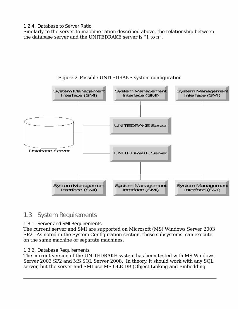
The UNITEDRAKE system is designed with the concept that customers should be able to choose whichever system configuration and security policies best meet their needs and requirements. Therefore, it is possible to install the database, server andSMI on separate machines or on the same machine. A greater explanation of these configuration options is provided in the following subsections and Figure 2. For requirements, please see the System Requirements section.
1.2.1. Database Server ConfigurationIn theory, it should be possible to segment information stored on the SQL server using database replication technologies. UNITEDRAKE supports the use of MS Cluster Service (MSCS) for the database server.
1.2.2. Server Interface with SMI and DatabaseThe UNITEDRAKE server exposes a COM (Component Object Model) interface that clients (such as the SMI) use to request services from the server (i.e. submit client commands) and receive notification events from the server.
1.2.3. Server to Machine Ratio, Server to SMI RatioThe server is constructed in such a way as to allow only one instance of a server to run on a particular machine. However, one instance of a UNITEDRAKE server can support connections from more than SMI. By utilizing Distributed COM (DCOM), SMIs on different machines can connect to the same UNITEDRAKE server and command the same clients.
9
1.2.4. Database to Server RatioSimilarly to the server to machine ration described above, the relationship between the database server and the UNITEDRAKE server is “1 to n”.
Figure 2: Possible UNITEDRAKE system configuration
Database Server
UNITEDRAKE Server
SystemManagement
Interface (SMI)
SystemManagement
Interface (SMI)
SystemManagement
Interface (SMI)
SystemManagement
Interface (SMI)
SystemManagement
Interface (SMI)
SystemManagement
Interface (SMI)
UNITEDRAKE Server
1.3 System Requirements
1.3.1. Server and SMI RequirementsThe current server and SMI are supported on Microsoft (MS) Windows Server 2003SP2. As noted in the System Configuration section, these subsystems can execute on the same machine or separate machines.
1.3.2. Database RequirementsThe current version of the UNITEDRAKE system has been tested with MS Windows Server 2003 SP2 and MS SQL Server 2008. In theory, it should work with any SQL server, but the server and SMI use MS OLE DB (Object Linking and Embedding
1
0
Database) technology to manage the connections to the database. Hence, the database vendor must provide an OLE DB provider for the SQL server
1.3.3. Client RequirementsThe UNITEDRAKE client versions 4.08.x and above support 32 and 64-bit versions for the following operating systems (where applicable):
Windows XP, SP1, SP2, SP3 Windows Server 2003 (all editions), SP2 Windows Vista and Server 2008 SP2 and below Windows 7 SP1 and below Windows 8 and Windows Server 2012
1.3.4. The Basic System Requirements UNITEDRAKE installation package which installs the server and SMI. Windows Server 2003 Standard x64 Edition (32/64-bit client support) MS SQL Server 2008
1.3.5. Additional Requirements Multilanguage: install all languages to be displayed on the SMI machine(s) UNITEDRAKE utilities for diagnostic logging and troubleshooting
1.3.6. Minimum Requirements Windows Server 2003 R2 Enterprise Edition, English Version with all optional
languages installed. MS SQL Server 2008 database with all of the latest updates. Pentium IV, 800 MHz. 1024 MB RAM. 40 Gigabyte hard disk.

1
1
2. System Installation
2.1 Server/Database
UNITEDRAKE server uses a windows installer package. This will guide theadministrator through the entire process. The UNITEDRAKE server supportsexecution as an NT service, a daemon process that can be automatically started aspart of the system boot process. By default, the UNITEDRAKE server is installed asa service. If this is not the desired behavior, it will have to be manually configuredby the system administrator once installation is complete. The UNITEDRAKEdatabase installation occurs automatically as part of the server installation.
Before beginning the installation, be sure to have the database logon and passwordavailable. This information will be required to complete the installation. This mustbe a database login with sufficient permissions to create a database and to create adatabase user.
To begin the process, insert the installation media into the computer. Run the setupfile (i.e. URServer_win32_4.06.xx.xxxx_setup.exe) from the installation media. Oncethe installer is initialized, the user will be guided through a series of dialogs. Theuser can use the Cancel button at any time to cancel the installation, or click Next to move to the next dialog.
The default setup type is Binaries, which will only install the binary files to the local system; this is to facilitate multiple UNITEDRAKE server instances for ease of deployment. No database interaction will be performed. Most importantly, it will install the SMI, the server (with the tipoff driver), and all of the built-in plug-in modules, as well as some utility programs.
The setup named Upgrade Old Database will upgrade an existing NON-3NF UR Database, notice that it will not create an old database and will only run database scripts.
In order to install binaries to the local system and run database scripts select the Custom setup option, which also allows the user to select the installation directory. The custom setup option provides the most flexibility and should be used by
Chapter
2
1
2
advance users only. The most frequently used scenario is to run database script with the old database and install binaries
To update a database and install binaries, select the following features: AllBinaries and UR Old Database Scripts.
Once all the information is gathered, the user will be presented with the current installation options and given one last chance to cancel or return to previous options. Once the installer configures the system, a final screen will be displayed and the system will be operational.
2.2 System Management Interface (SMI)
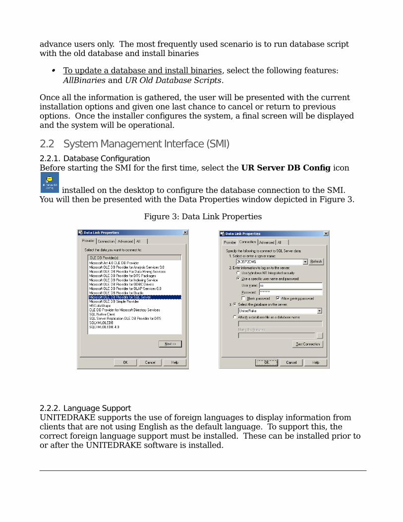
2.2.1. Database ConfigurationBefore starting the SMI for the first time, select the UR Server DB Config icon
installed on the desktop to configure the database connection to the SMI. You will then be presented with the Data Properties window depicted in Figure 3.
Figure 3: Data Link Properties
2.2.2. Language SupportUNITEDRAKE supports the use of foreign languages to display information from clients that are not using English as the default language. To support this, the correct foreign language support must be installed. These can be installed prior to or after the UNITEDRAKE software is installed.
1
3
2.2.3. Collected Email DisplayIf the Exchange plug-in software is installed, MS WORD 2000 or later should be installed to support displaying collected email messages.
2.3 Plug-in Modules
Previous versions of the UNITEDRAKE server had several “Built-in” plug-in moduleswhich were automatically installed. With this version of the UNITEDRAKE Server, Transports as well as InfoSpyder, WhiteSpyder and NetSpyder are separate installations.
IMPORTANT NOTE: The server will not start unless there is at least one transport (HTTP or TCP) installed. Either install the transports before installingthe server, or install the transports after the server has been installed, but before the system is rebooted.
3.
1
4
System Administration
3.1 Database
Since UNITEDRAKE supports any SQL database system with an MS (Microsoft) OLE DB provider for Windows, this manual does not include any information concerning the administration of the database server.
3.2 Server
The UNITEDRAKE server is a sophisticated piece of software that is designed to function as an NT service. Once it is correctly installed, it requires minimal intervention. However, it may be necessary to change the settings of the UNITEDRAKE server to support the current security policy of the system. This requires detailed understanding of the configuration of NT services and COM servers. In general, all tasks can be completed using the SCM (Service Control Manager) and the DCOMCNFG programs. The SCM is accessed from Start->Settings->Control Panel->Administrative Tools->Computer Management. The following is an example of how the SCM would display one configuration of the UNITEDRAKE server:
Figure 3 Service Control Manager (SCM)
By double clicking on the URServer service, a dialog box will be displayed,prompting the user for the appropriate information. For example, by default, theSCM is configured to take no action in the event that the UNITEDRAKE server exitsabnormally. The user may wish to change this to take the appropriate action.
Chapter
3
1
5
IMPORTANT NOTE: The SCM can be used to start and stop the URServer service. Care should be taken when exercising this option as currently connected clients will have to timeout before new connections can be initiated if the server is restarted.
Security policy may require that from time to time, the database logon and/or password be changed. The server installation includes the “svrdbconfig.exe” utility (UR Server DB Config icon on the desktop) that allows this information to be updated. This is the only way to update this information since the connection data is stored encrypted on the server. This utility will prompt the user for the appropriate data link connection information. Once this information is updated, theURServer service should be restarted using the SCM.
The installer creates a database account, “urservices” and uses a strong password.Rather than prompt the user at installation time, this account is used to configure the security setting for the server. If the security settings already exist, they are notoverwritten. It is not recommended that this account be used to access the database from any application other than the UNITEDRAKE server or other serviceswhich are additions to the UNITEDRAKE system.
3.2.1. TipofAlong with the URServer, a device driver, ur.sys, is installed on the system. This is used to manage client connection ‘tipoff’. This service appears in the windows SCMinterface under Start->Programs->Accessories->System Tools -> System Information. Within the interface, select Software Environment -> System Drivers. This driver is configured to start on demand and will appear to be stopped until a connection tipoff is initiated.
3.2.2. Web Page SupportThe UNITEDRAKE server monitors all incoming connection requests on port 80 andif an invalid request is received, it will attempt to service it as a normal HTTP connection. In order to do this, several web pages must exist on the system. The names and locations of these pages are stored in the registry. Default values and pages are setup during system installation.
All registry values are stored in HKEY_LOCAL_MACHINE\SOFTWARE\Wow6432Node\UnitedRake\Transport\HTTP (HTTP Transport) or HKEY_LOCAL_MACHINE\SOFTWARE\Wow6432Node\UnitedRake\Transport\HTTP2. This key contains the following values:
1
6
WebRoot – the directory where all web pages are installed. By default, this is the webroot directory in the installation directory.
Error 400 – the name of the file to return when error 400 is encountered. By default, this is \ERROR400.html.
Error 404 – the name of the file to return when error 404 is encountered. By default, this is \ERROR404.html.
Error 501 – the name of the file to return when error 501 is encountered. By default, this is \ERROR501.html.
ServerName – the name of the “web server”. The default value is “Microsoft – IIS/6.0”.
MaxSimConnections – the maximum number of connections allowed. Currently this is 600.
WaitForDataDelay – the number of milliseconds to wait before serving up a web page. The default is 2000.
The HTTP2 key contains an additional value: StegoPercent - The default value is 25
Any files placed in the “webroot” directory will be available as web pages.3.2.3. UNITEDRAKE Service ManagerThe UNITEDRAKE Service Manager is the UNITEDRAKE server utility for working with the server service. This application normally runs as a “tray icon” in the task bar and is often referred to as the "Green Guy".
Figure 4 Tray Icon
As shown above in Figure 5, the green icon on the left represents the service manager control program. Clicking with the right mouse button activates a menu which has five items. Start Service, Stop Service, and Restart Service are used to run and/or stop the service. Exit will exit the program. Open displays the window depicted in Figure 3 which can be used to control the service.
1
7
Figure 5 Server Tray Icon Tool (Green Guy)
The buttons on the right provide the following functionality:
Start Service – Start the server service.
Stop Service – Stop the server service.
Restart Service – Stop then start the server service.
Refresh Settings – Reload the current configuration from persistent storage.
Save Changes – Store any modifications to the parameters.
Dismiss – Hide this window.
Exit – Exit the program.
Under the Transport field of the window is a list of ports that the server can be configured to “listen” on. By default, the UNITEDRAKE server is configured to listen for TCP/IP connections on port 443. Additional or alternate ports can be enabled by adding them to this list by using the New button. To delete a transport, first select it and then click on the Delete button.
As was previously mentioned, the UNITEDRAKE server accesses the databaseserver using an encrypted configuration which can be set using the
1
8
“svrdbconfig.exe” program. This configuration can also be set using this application. The current server and user name are displayed in the center of the application and can be modified using the Edit DB Config button.
IMPORTANT NOTE: Once the configuration has been changed, it must be persisted using the Save Changes command. If the server isrunning, the changes will not take effect until the service is restarted.
3.2.4. Multi HomingAs of server version 4.4, UNITEDRAKE supports multi-homing. The server will listen for the configured ports on all IP address of the system except for loopback (127.0.0.1). This applies to multiple NIC cards as well as multiple IP addresses for agiven NIC card. This is automatic and requires no interaction from the user. Previously, only the first reported IP address would be listened on.
3.3 System Management Interface (SMI)
The SMI, also known as the UR GUI, requires no administration at this time.However, it may be the case that the UNITEDRAKE server is running on a differentsystem than the SMI. In this scenario, the server will have to be configured for“remote activation” using “DCOMCNFG” or some other utility.
3.4 Plug-in Modules
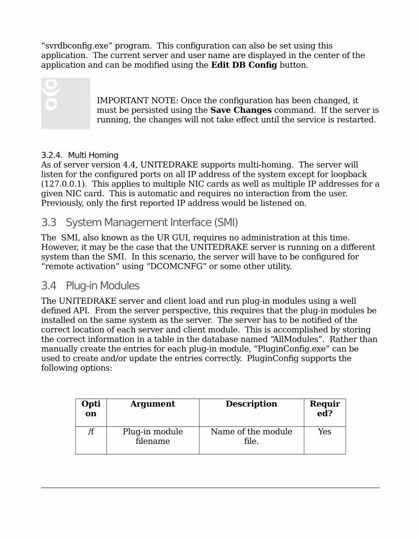
The UNITEDRAKE server and client load and run plug-in modules using a well defined API. From the server perspective, this requires that the plug-in modules be installed on the same system as the server. The server has to be notified of the correct location of each server and client module. This is accomplished by storing the correct information in a table in the database named “AllModules”. Rather thanmanually create the entries for each plug-in module, “PluginConfig.exe” can be used to create and/or update the entries correctly. PluginConfig supports the following options:
Option
Argument Description Required?
/f Plug-in modulefilename
Name of the modulefile.
Yes
1
9
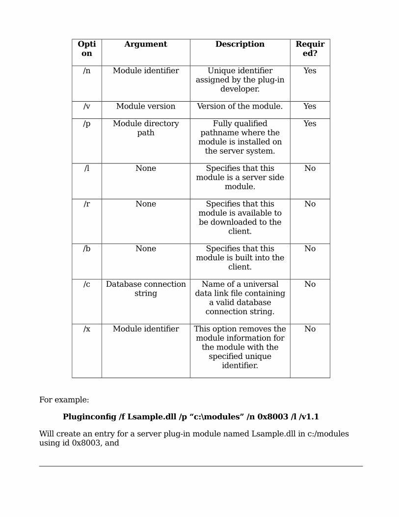
Option
Argument Description Required?
/n Module identifier Unique identifierassigned by the plug-in
developer.
Yes
/v Module version Version of the module. Yes
/p Module directorypath
Fully qualifiedpathname where themodule is installed on
the server system.
Yes
/l None Specifies that thismodule is a server side
module.
No
/r None Specifies that thismodule is available tobe downloaded to the
client.
No
/b None Specifies that thismodule is built into the
client.
No
/c Database connectionstring
Name of a universaldata link file containing
a valid databaseconnection string.
No
/x Module identifier This option removes themodule information for
the module with thespecified unique
identifier.
No
For example:
Pluginconfig /f Lsample.dll /p “c:\modules” /n 0x8003 /l /v1.1
Will create an entry for a server plug-in module named Lsample.dll in c:/modules using id 0x8003, and
2
0
Pluginconfig /x 32768
will remove the entry for the plug-in module with identifier 32768.
IMPORTANT NOTE: It is generally expected that plug-in modules will be installed using a standard mechanism for installing windows components, such as a windows installer package. As part of the installation, the plug-in configuration information should be entered into the database automatically. PluginConfig should be used with extreme caution to either repair corrupted or remove unused
database entries.
3.5 User InterfaceControls
A “control” is a self-contained user interface component that allows the operator tosubmit commands to the clients. Each control is independent of the other controlsand new controls can be added to the system at any time. The SMI is a hostapplication that determines which controls are available and displays them to theoperator.
Typically, a control will be associated with one or more remote plug-in modules.The SMI determines which controls should be displayed by examining the currentstate of the client and a table in the database, “UICtrlReqModules”. Each control is“registered” with the system using the SMI. Under the Modules menu of the SMI, there are two items, Install UI Control and Edit UI Control.
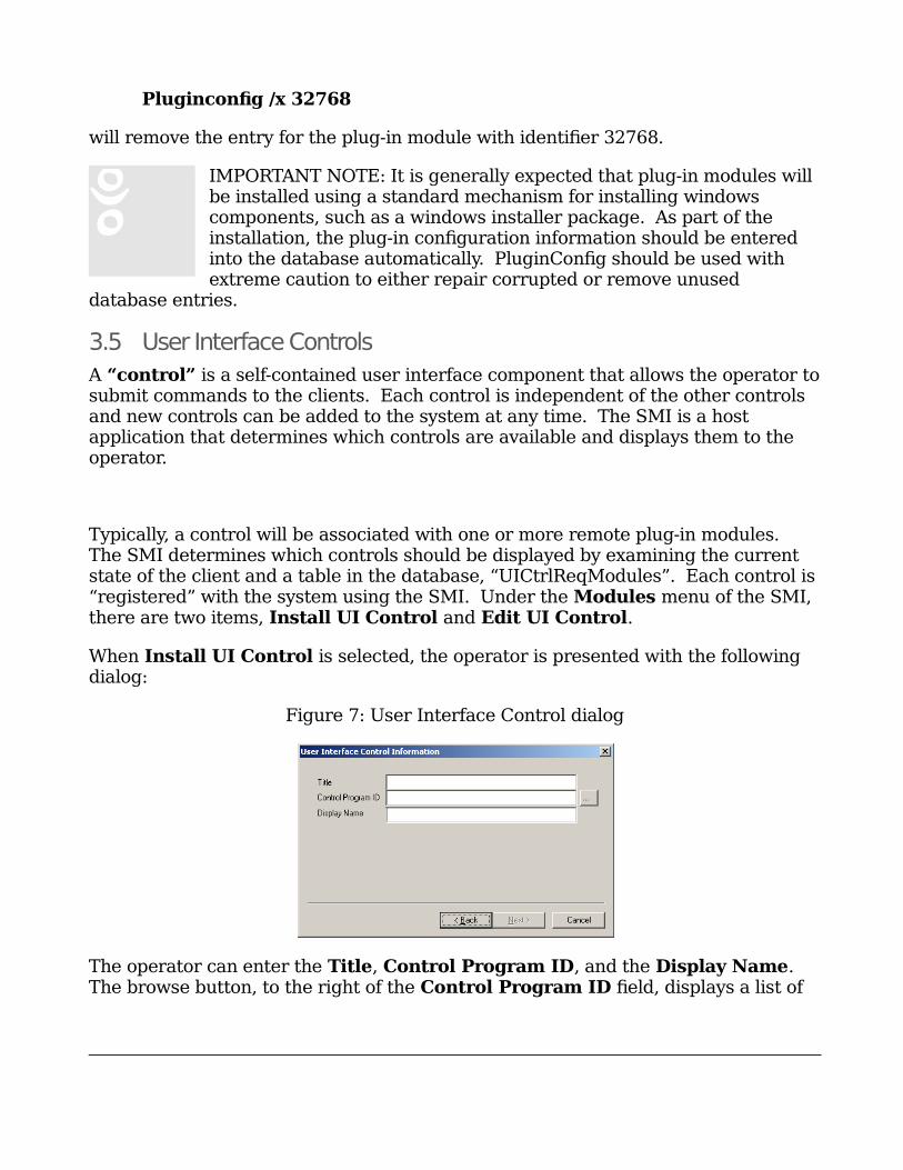
When Install UI Control is selected, the operator is presented with the following dialog:
Figure 7: User Interface Control dialog
The operator can enter the Title, Control Program ID, and the Display Name. The browse button, to the right of the Control Program ID field, displays a list of
2
1
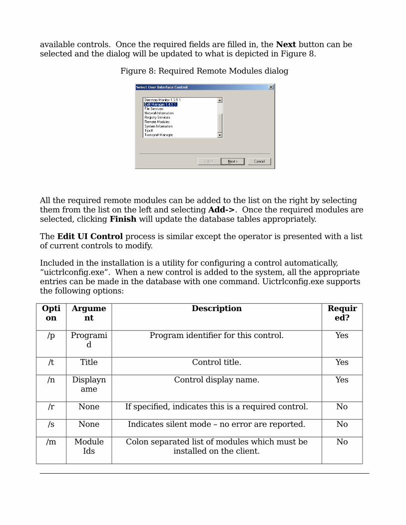
available controls. Once the required fields are filled in, the Next button can be selected and the dialog will be updated to what is depicted in Figure 8.
Figure 8: Required Remote Modules dialog
All the required remote modules can be added to the list on the right by selecting them from the list on the left and selecting Add->. Once the required modules are selected, clicking Finish will update the database tables appropriately.
The Edit UI Control process is similar except the operator is presented with a list of current controls to modify.
Included in the installation is a utility for configuring a control automatically, “uictrlconfig.exe”. When a new control is added to the system, all the appropriate entries can be made in the database with one command. Uictrlconfig.exe supports the following options:
Option
Argument
Description Required?
/p Programid
Program identifier for this control. Yes
/t Title Control title. Yes
/n Displayname
Control display name. Yes
/r None If specified, indicates this is a required control. No
/s None Indicates silent mode – no error are reported. No
/m ModuleIds
Colon separated list of modules which must beinstalled on the client.
No

2
2
For example:
Uictrlconfig /p CtrlLib.Ctrl.1 /t Control /n Name /m 32409:34568 /r
will create entries in the database for a required control (i.e. always created when aclient is opened) that is dependent on remote modules 32409 and 34568.
2
3
4. Users’ Manual
4.1 System Management Interface (SMI)
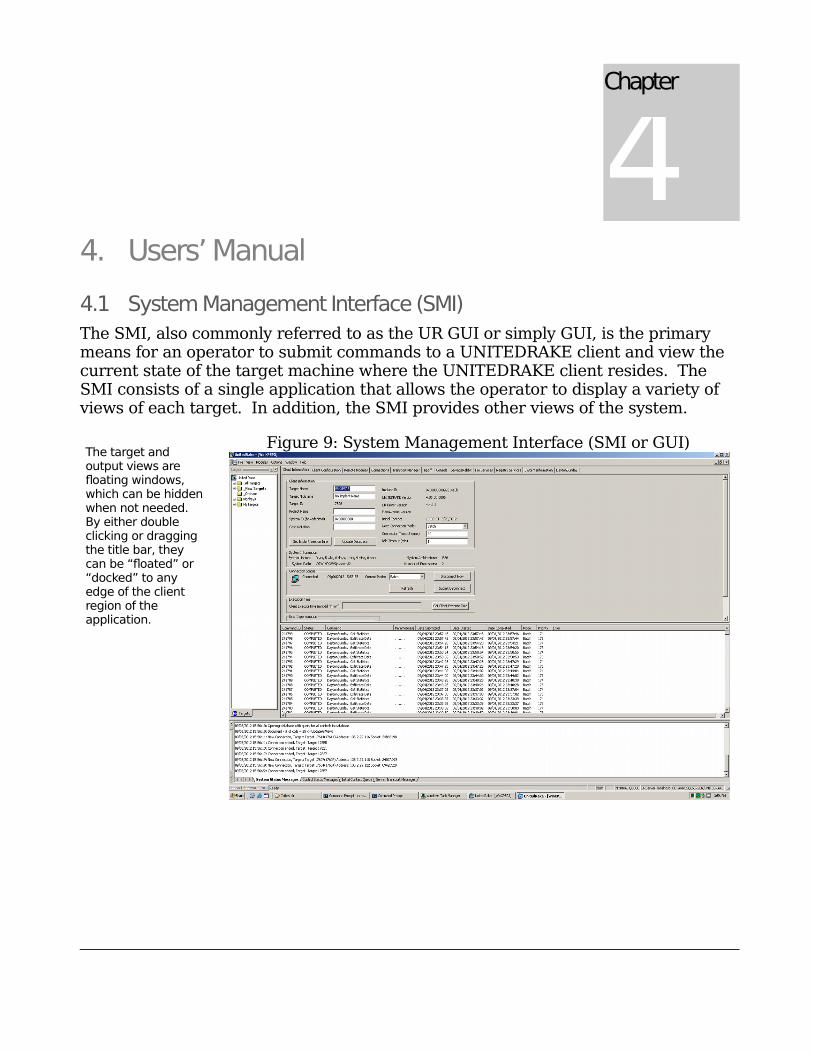
The SMI, also commonly referred to as the UR GUI or simply GUI, is the primarymeans for an operator to submit commands to a UNITEDRAKE client and view thecurrent state of the target machine where the UNITEDRAKE client resides. TheSMI consists of a single application that allows the operator to display a variety ofviews of each target. In addition, the SMI provides other views of the system.
Figure 9: System Management Interface (SMI or GUI)
Chapter
4
The target and output views are floating windows, which can be hiddenwhen not needed. By either double clicking or dragging the title bar, they can be “floated” or “docked” to any edge of the client region of the application.

2
4
4.2 Optional Views – Client and status information.
In Figure 9, the window on the left is referred to as the Target Pane1. It consists ofa list of system and user defined groups.
4.3 Target Pane
The SMI displays a target pane with several functions in mind. This pane is designed to make target location and grouping much simpler and to also speed up the SMI by only updating the connection state of targets of interest. The target pane has a windows explorer style tree structure with a little variety, as seen in Figure 10 below.
Figure 10: Target Pane
4.4 Default Groups
There are several built-in groups in the target pane that have certain restrictions and special functionality, they are as follows:
4.4.1. United RakeThis group is the top level group. It may only contain groups, not targets. It also cannot be collapsed like other groups. It has a unique icon and does not have a corresponding entry in the database. Its main function is to serve as the tree root.
1 If the targets pane is not visible, it can be displayed by toggling the Targets button on the context menu that is displayed when the right button is clicked on any menu or toolbar or by toggling the Targets button on the View menu.
2
5
4.4.2. _All TargetsThis group will contain a list of every target in the target table. You may copy from this group, but you may never delete or move targets out of this group. You also may not move or copy targets or groups into this group.
4.4.3. _New TargetsWhen a target connects that is not already part of the _All Targets group, it will be added to this group (and also added to _All Targets). As long as there are targets in this group, the name of the group will show in BOLD to bring attention to it.
Targets will remain in this group until moved or deleted.
NOTE: Deleting a target from this group will only remove it from this group, it will remain in _All Targets. You may move targets out of this group, as well as delete and copy them from this group, but you may not
add targets or groups to this group. It is only populated automatically by the SMI itself when a new target connects.
4.4.4. _OrphansOn extremely rare occasions, a group may be identified as belonging to another group even though that “parent” group does not exist. If the SMI detects such a condition, the group will be placed within the _Orphans group until moved or deleted. You may move or copy from this group, but you may not move or copy into it. You may also delete groups in _Orphans.
NOTE: You cannot delete, rename or move any of the default groups. _All Targets,_New Targets, and _Orphans have a preceding underscore so that they remain at the top of the target pane.
4.5 Context Sensitive Menus
The target pane has context sensitive menus. A different menu will pop up depending on which type of item is selected in the tree. Items in the menu will be enabled or disabled (grayed out) depending on the certain conditions. Here are some of the functions available from the menus.
4.5.1. From all menusFind Target – This is a very basic search function that allows a user to find a specific target in a specific folder. The search will find target names that contain spaces (i.e. DIAMONDAXE 447) but will not do wildcard searches (i.e. DIAMOND*). NOTE: It is suggested to highlight a target in the _All Targets folder and then right click on that target to select the Find Target option.
Refresh – When the tree is built initially and when new targets are added, the default target icon is used, which does not necessarily reflect the current connection status of the target. To get a more accurate picture of target status,
2
6
click on Refresh, or press the F5 key (if this pane has windows focus). NOTE: Thiswill only update visible targets, to help speed up SMI processing.
Set Refresh Time – By default, the target pane will automatically refresh every 60 seconds. If you would like to change this refresh time, select this option and then set the new time in seconds. You will get a pop-up dialog asking for the new time in seconds. NOTE: Refresh time is only for connection status. New targets will show up in the New Targets group at the time of connection regardless of this setting.
Rebuild Tree – Occasionally the current state of the display may not match the database. The current view is a snapshot of the database at the time the SMI is loaded. This could happen if there are more than one copies of the SMI loaded and different people are editing groups, for example. To force a rebuild of the tree, so that it matches any changes to the database, choose this option. NOTE: New targets that connect and are not currently in the All Targets group, should be updated on all SMI clients without forcing a rebuild. This option is mostly to updateuser defined groups.
Lock – Locks or Unlocks the target pane. When the pane is locked, you will not be able to make changes. This is to prevent inadvertently moving targets or groups around while browsing. This is a toggle and will be checked when the pane is locked.
Undo – Will undo the last copy, delete, or move operation. Undo for Rename is not currently supported. Renaming currently disables any available undo. This prevents trying to move back to a group that has changed.
4.5.2. Group menusThe target pane will need to be unlocked to be able to see and use the following target pane menu options.
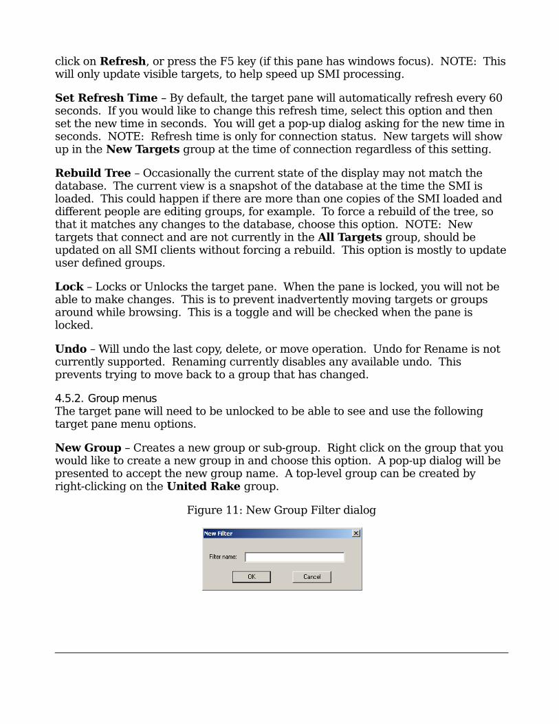
New Group – Creates a new group or sub-group. Right click on the group that youwould like to create a new group in and choose this option. A pop-up dialog will bepresented to accept the new group name. A top-level group can be created byright-clicking on the United Rake group.
Figure 11: New Group Filter dialog
2
7
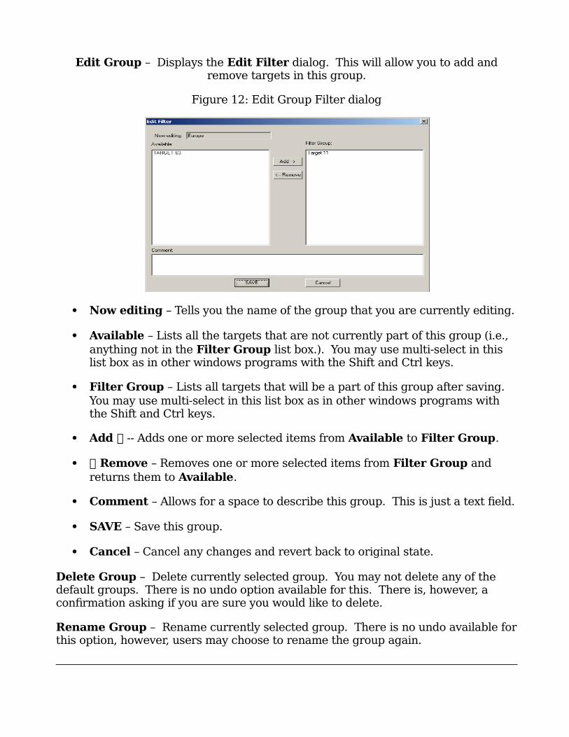
Edit Group – Displays the Edit Filter dialog. This will allow you to add andremove targets in this group.
Figure 12: Edit Group Filter dialog
Now editing – Tells you the name of the group that you are currently editing.
Available – Lists all the targets that are not currently part of this group (i.e.,
anything not in the Filter Group list box.). You may use multi-select in this list box as in other windows programs with the Shift and Ctrl keys.
Filter Group – Lists all targets that will be a part of this group after saving. You may use multi-select in this list box as in other windows programs with the Shift and Ctrl keys.
Add -- Adds one or more selected items from Available to Filter Group.
Remove – Removes one or more selected items from Filter Group and
returns them to Available.
Comment – Allows for a space to describe this group. This is just a text field.
SAVE – Save this group.
Cancel – Cancel any changes and revert back to original state.
Delete Group – Delete currently selected group. You may not delete any of the default groups. There is no undo option available for this. There is, however, a confirmation asking if you are sure you would like to delete.
Rename Group – Rename currently selected group. There is no undo available forthis option, however, users may choose to rename the group again.
2
8
4.5.3. Target menusConnection Log – Brings up the connection log for this target.
Set Client as Denied – Sets this client as denied.
Rename Target – Renames this target, will update in all groups.
Delete Target – Delete this target from this group only. This does not remove the target from the database.
4.6 Drag and Drop
The target pane allows for drag and drop operations. Drag and drop works with thefollowing conditions and limitations.
Drag and drop operation is disabled when the target pane is locked with the
Lock menu option.
The default drag and drop operation is to move an item.
Hold the “Ctrl” key on the keyboard during a drag and drop operation to copyan item. During a copy operation the mouse pointer will change to a copy pointer (will have a plus sign).
Targets can be moved or copied.
Groups can be moved, but NOT copied.
You may NOT copy or move any item to one of the default groups (_New Targets, _All Targets, _Orphans), or any sub-groups if there happen to be any.
You may NOT copy or move any targets to the root level (United Rake), you may move or create new groups there, however.
You may NOT move any targets from the _All Targets group. You may copy from it, however.
You may NOT drop a group onto a target.
4.7 Output View
The output view, at the bottom of the display, is the primary method for providing system information to the operator. It consists of four tabs, System Status Messages, Control Status Messages, Initial Contact Queue, and Server Transport Messages.
2
9
The system status messages are primarily status and error information from the server the interface is currently connected to. All of the messages in this window are stored in the log file. Additional messages that are not logged will appear in thestatus bar at the bottom of the application window.
The control status messages include information from each of the individual user interface controls.
The initial contact queue is a list of tasks that are executed the first time a client connects to the server. There is a context menu that is activated by clicking the right mouse button on the initial contact queue window that will allow the user to manage the initial contact queue tasks.
The server transport messages tab displays transport level diagnostic information from the UNITEDRAKE server. The amount of information which can appear here is quite large, so by default, it is disabled. However, View Transport Messages under the Options menu can be used to enable this display if necessary.
In the event that the operator chooses to hide either of these windows, they can be redisplayed using the View menu or the context menu that is activated by right clicking on the main menu bar.
4.8 Command Line Options
The SMI has several command line options which can be used to control which UNITEDRAKE server the program connects to2. The “-promptserver” option will result in the operator being prompted for the name of host which is running the UNITEDRAKE server. An attempt to connect to this server will be made rather thanusing either the local host or the host specified in the registry settings. The “-server<servername>” option will result in an attempt to connect to the UNITEDRAKE server running on host “servername”.
4.9 Main Menu
Most of the commands located on the main menu and its associated submenus are the standard “windows application commands”. For example, the Window menu allows the operator to arrange (tile or cascade) client views, create additional views of open clients, and set the current active client view.
2 Previously, this information had to be configured in the registry using either complicated registry scripts or the “dcomcnfg” program. There are two main advantages to this. First, if the server is not installed on the SMI host, no registry information exists. Secondly, multiple SMI’s can be run on the same machine, all connected to different servers.
3
0
4.10 File Menu
Most of the commands on the File menu are the standard windows application file menu commands. For example, the Open command opens the currently selectedclient.
The File menu contains the Load Targeting Info command which is used to load target identifiers such as system identifier or case notation from an xml file. PUZZLECUBE has been modified to produce an xml file with the correct information. This command will prompt for the file and then prompt for the correct client to assign the information to.
The Collection Management submenu that is comprised of Set Client As Denied and Manage Collection Status commands. Set Client As Denied will add a specified client to the “access denied” list. The access denied list consists of a list of eight byte unique identifiers (UR Client ID’s) and the FISA (Foreign Intelligence Surveillance Act) expiration date. Each client is assigned an identifier during deployment or automatically upon activation. When attempting to connect, the client sends its identifier to the server. If the server detects the sent identifier in thedeny list, the connection is refused and no logging of the connection is recorded.
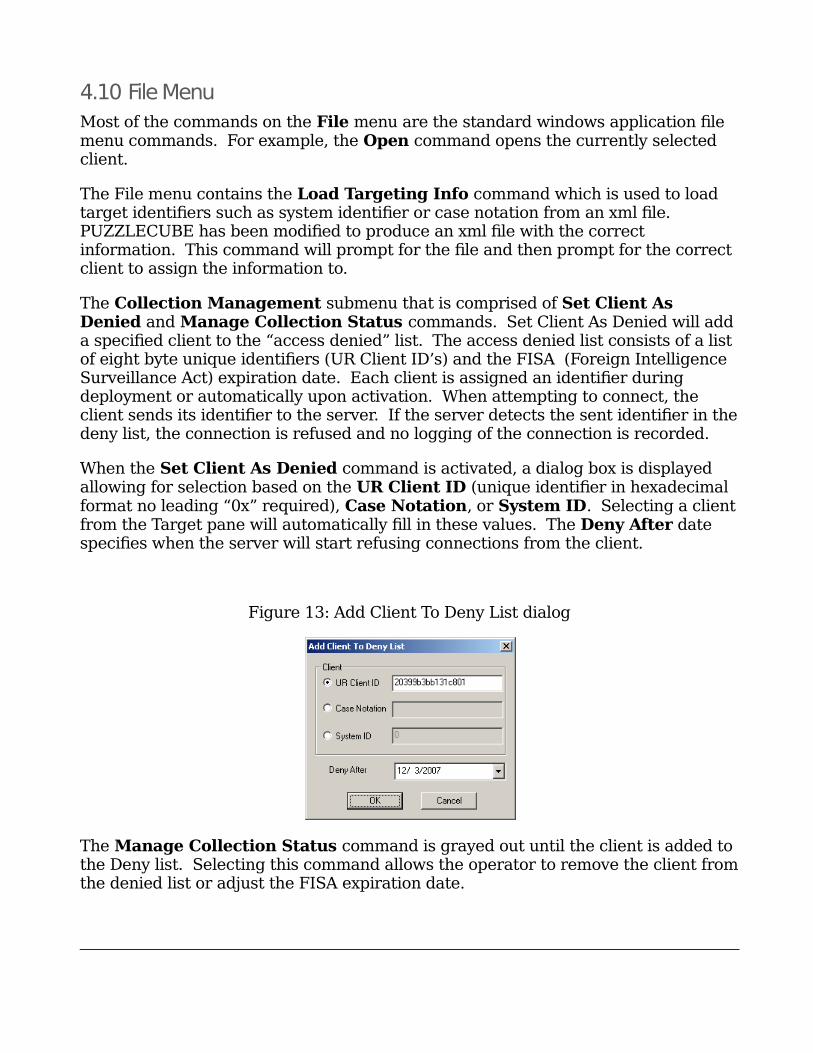
When the Set Client As Denied command is activated, a dialog box is displayed allowing for selection based on the UR Client ID (unique identifier in hexadecimal format no leading “0x” required), Case Notation, or System ID. Selecting a clientfrom the Target pane will automatically fill in these values. The Deny After date specifies when the server will start refusing connections from the client.
Figure 13: Add Client To Deny List dialog
The Manage Collection Status command is grayed out until the client is added to the Deny list. Selecting this command allows the operator to remove the client fromthe denied list or adjust the FISA expiration date.
3
1
The Load Tasking command is used to manually load xml tasking files which match the schema documented as part of the BLUISHDEFER subsystem. The user will be prompted for both an input Tasking File and a Schema File. Schema validation is not required so this can be left blank. The tasking file will be parsed for commands and translated using “mapping” files. Mapping files are xml files which are used to convert xml tasking to an internal format. If an appropriate mapping file can not be found, the operator can browse for one or skip the command. The search path for mapping files can be set using Tasking Mapping Files Directory under the Options menu.
4.11 View Menu
The View Menu is used primarily to control which windows are displayed. For example, the Status, Output, Targets, and Queue windows can be hidden or displayed using the toggle buttons on this menu.
The Full Screen command displays the current client view as a full screen window without the main menu bar To restore the main menu bar simply click on the icon inthe upper right corner.
The Log File command displays the contents of the current log file in a dialog with the following options: Truncate, Refresh, Save As, Mail To, and Close
4.12 Modules Menu
The Modules menu is used to manage the configuration of user interface control modules. This is a system administrative type task and is discussed in the System Administration portion of this document.
4.13 Options Menu
The Options menu items are specific to UNITEDRAKE.
Log Filename command prompts the operator for a new log filename. This value is stored and will be used by subsequent sessions until it is reset.
Integrated DB Authentication command is a toggle. When it is active, the SMI will attempt to authenticate the operator with the database server using standard Windows NT authentication. If the database server does not support NT authentication or this feature is deactivated, the SMI will not be authenticated on the DB server. The operator will be prompted to enter the appropriate authentication information when the application is started. Please contact the system administrator to determine the appropriate setting for this option.
View Transport Messages command is used to disable the display of transport messages in the Output view. These messages are primarily diagnostic in nature
3
2
and under normal operation are of little value to the operator. These messages will still be logged, even if they are hidden from the operator.
Log Transport Messages command is used to enable/disable the logging of transport event messages. When transport messages are logged, the log file grows very quickly. Since this information is primarily diagnostic in nature, it is recommended that this feature be disabled.
Prompt On Load Queue command is used to enable/disable prompting for loadingcommands into the queue from a file.
Tasking Mapping Files Directories is used to set the mapping files directories used to translate tasking in BLUISHDEFER format. More than one search directorycan be added to the list.
Disable Server Event Processing is used to cause the user interface to ignore server events. This option is useful if the server is heavily loaded or the user just wants to review current information.
4.14 Window Menu
The Window menu is used to control the client views and operates in exactly in the same manner as most other windows applications. For example, the New Window menu item creates a duplicate view of the current client. NOTE: With the New Window option, a duplicate window frame is created but to view the client tabs you must click on the desired client target in the target pane.
4.15 Client views
Each client view consists of a “tabbed” view with a single “control” in each tab. It might be useful to think of a control as an interface for a collection of related client tasking functions. For example, normally, the first tab contains a Client Information control, which displays the current state of the client, the connection mode, server configuration parameters, and client information. There are other controls that provide client configuration management, remote plugin module management, connection logging, task queue management, and so forth.
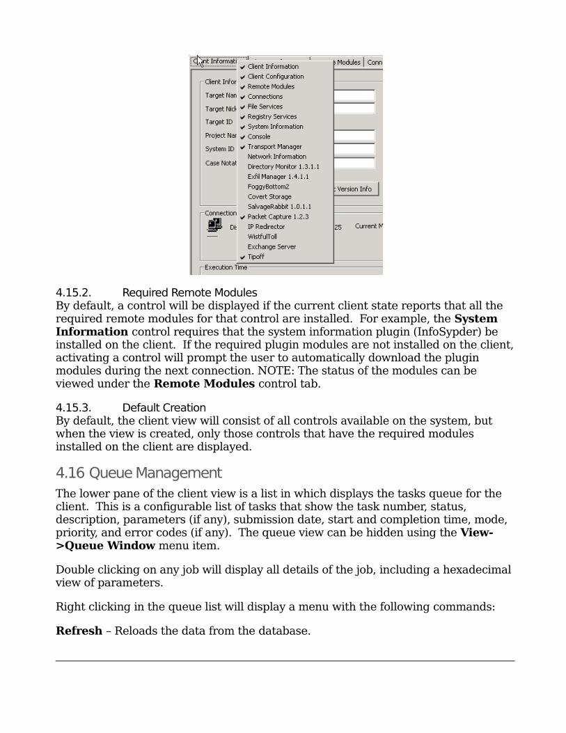
4.15.1. Tab VisibilityBy right clicking any of the tabs, the operator can control which tabs are visible.
Figure 14: Control Visibility Menu
3
3
4.15.2. Required Remote ModulesBy default, a control will be displayed if the current client state reports that all the required remote modules for that control are installed. For example, the System Information control requires that the system information plugin (InfoSypder) be installed on the client. If the required plugin modules are not installed on the client,activating a control will prompt the user to automatically download the plugin modules during the next connection. NOTE: The status of the modules can be viewed under the Remote Modules control tab.
4.15.3. Default CreationBy default, the client view will consist of all controls available on the system, but when the view is created, only those controls that have the required modules installed on the client are displayed.
4.16 Queue Management
The lower pane of the client view is a list in which displays the tasks queue for the client. This is a configurable list of tasks that show the task number, status, description, parameters (if any), submission date, start and completion time, mode, priority, and error codes (if any). The queue view can be hidden using the View->Queue Window menu item.
Double clicking on any job will display all details of the job, including a hexadecimalview of parameters.
Right clicking in the queue list will display a menu with the following commands:
Refresh – Reloads the data from the database.
3
4
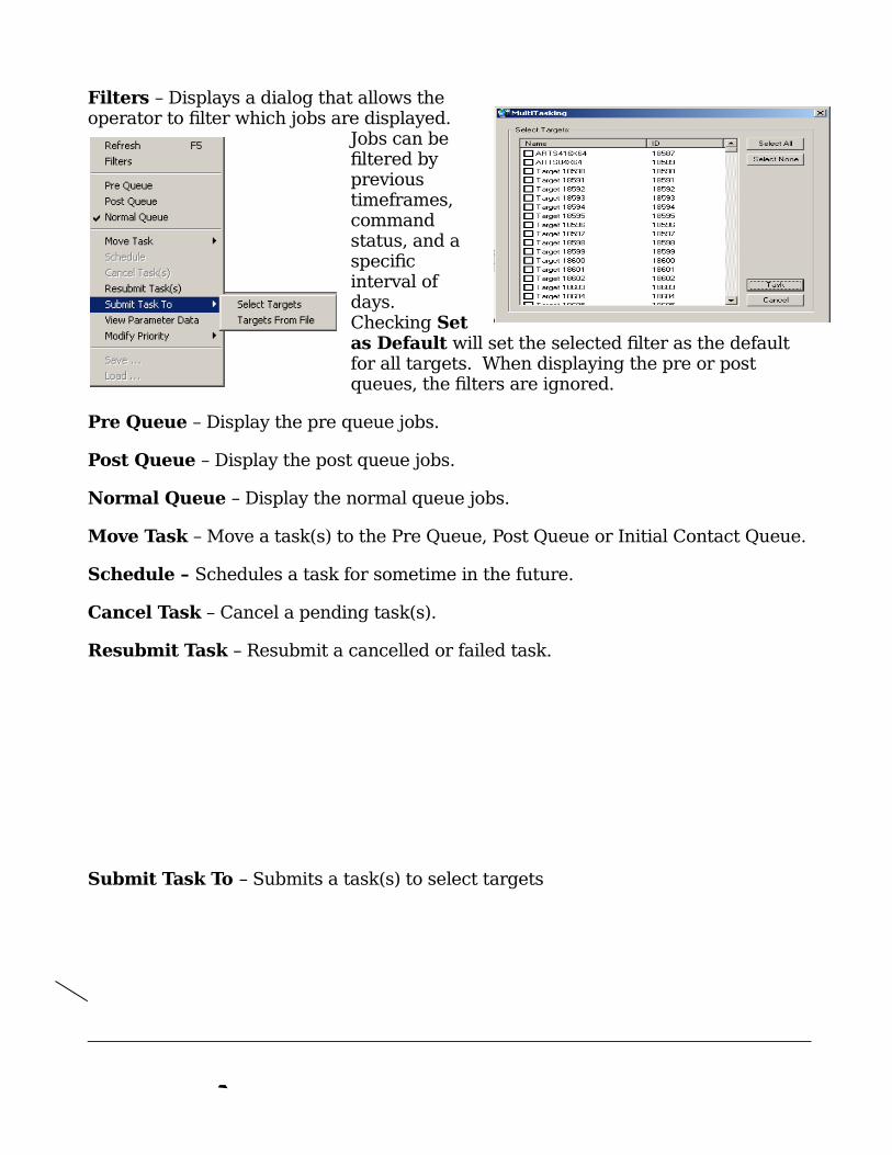
Filters – Displays a dialog that allows theoperator to filter which jobs are displayed.
Jobs can befiltered byprevioustimeframes,commandstatus, and aspecificinterval ofdays.Checking Setas Default will set the selected filter as the default for all targets. When displaying the pre or post queues, the filters are ignored.
Pre Queue – Display the pre queue jobs.
Post Queue – Display the post queue jobs.
Normal Queue – Display the normal queue jobs.
Move Task – Move a task(s) to the Pre Queue, Post Queue or Initial Contact Queue.
Schedule – Schedules a task for sometime in the future.
Cancel Task – Cancel a pending task(s).
Resubmit Task – Resubmit a cancelled or failed task.
Submit Task To – Submits a task(s) to select targets

3
5
View Parameter Data – Display the details ofthe selected task.
Modify Priority – Modify Priority to Urgent,High, Medium, Low, or user defined, as shownin Figure 15.
Figure 15: Modify Priority Menu
Modifying the priority changes the order in which pending commands are submitted to the implant by the server. The command with the lowest priority will be submitted first. Commands of the same priority will be submitted in order of
3
6
submission date, oldest to newest. Modify Priority can also modify multiple pendingcommands simultaneously. All selected pending commands will be modified to the specified priority. While in Restricted mode, priorities can be modified from 1 – 200. Restricted mode is described in the Systems Controls section of this document.
Save… – Save current tasks list as an xml file.
Load… – Load an xml file into the queue.
The Load and Save commands on the queue view menu do not support task lists in the BLUISHDEFER format. This is for historical reasons – this functionality was implemented prior to the establishment of the BLUISHDEFER standard and is available only to support previous versions. To load BLUISHDEFER tasking files, use the Load Tasking command on the main menu.
3
7
5. System Controls
5.1 Client Information Control
The Client Information control tab is used to display and set information about the UNITEDRAKE client and its current connection state.
Chapter
5
3
8
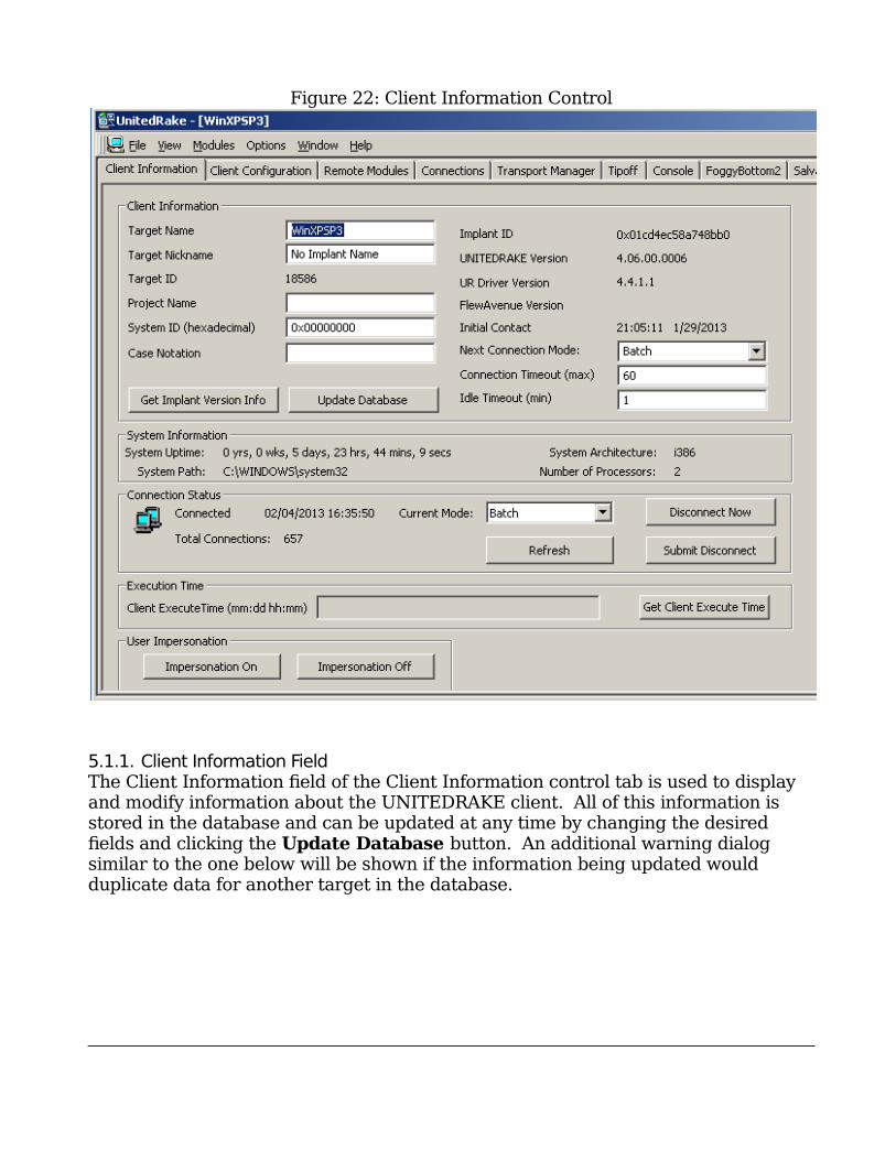
Figure 22: Client Information Control
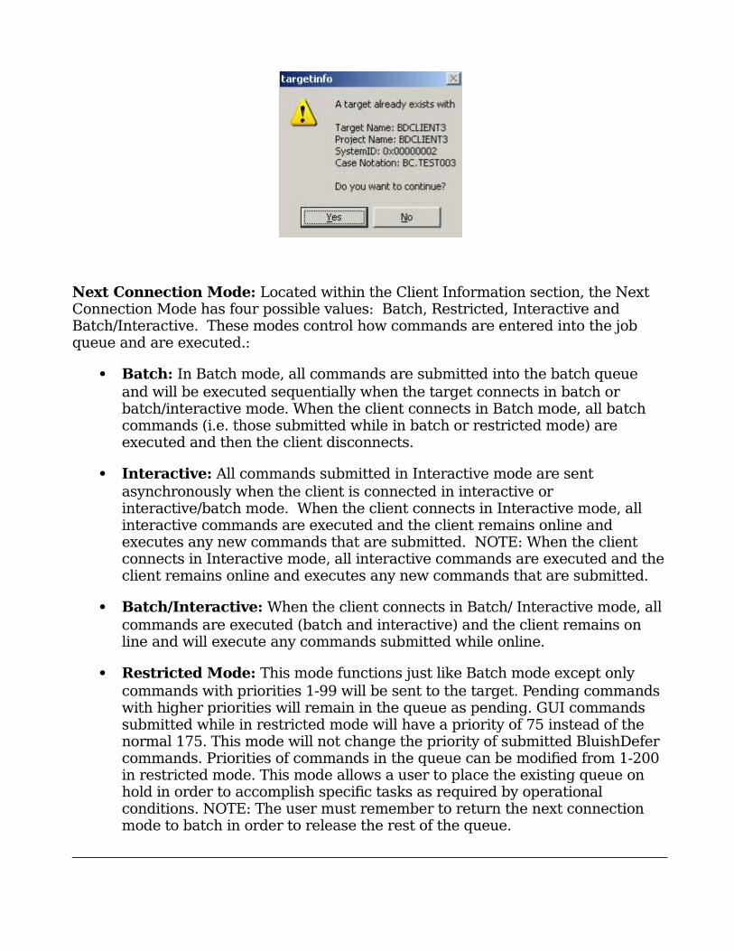
5.1.1. Client Information FieldThe Client Information field of the Client Information control tab is used to display and modify information about the UNITEDRAKE client. All of this information is stored in the database and can be updated at any time by changing the desired fields and clicking the Update Database button. An additional warning dialogsimilar to the one below will be shown if the information being updated wouldduplicate data for another target in the database.
3
9
Next Connection Mode: Located within the Client Information section, the Next Connection Mode has four possible values: Batch, Restricted, Interactive and Batch/Interactive. These modes control how commands are entered into the job queue and are executed.:
Batch: In Batch mode, all commands are submitted into the batch queue and will be executed sequentially when the target connects in batch or batch/interactive mode. When the client connects in Batch mode, all batch commands (i.e. those submitted while in batch or restricted mode) are executed and then the client disconnects.
Interactive: All commands submitted in Interactive mode are sent asynchronously when the client is connected in interactive or interactive/batch mode. When the client connects in Interactive mode, all interactive commands are executed and the client remains online and executes any new commands that are submitted. NOTE: When the client connects in Interactive mode, all interactive commands are executed and theclient remains online and executes any new commands that are submitted.
Batch/Interactive: When the client connects in Batch/ Interactive mode, all commands are executed (batch and interactive) and the client remains on line and will execute any commands submitted while online.
Restricted Mode: This mode functions just like Batch mode except only commands with priorities 1-99 will be sent to the target. Pending commands with higher priorities will remain in the queue as pending. GUI commands submitted while in restricted mode will have a priority of 75 instead of the normal 175. This mode will not change the priority of submitted BluishDefer commands. Priorities of commands in the queue can be modified from 1-200 in restricted mode. This mode allows a user to place the existing queue on hold in order to accomplish specific tasks as required by operational conditions. NOTE: The user must remember to return the next connection mode to batch in order to release the rest of the queue.
4
0
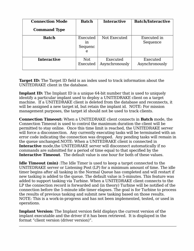
Connection Mode
Command Type
Batch Interactive Batch/Interactive
Batch Executedin
Sequence
Not Executed Executed inSequence
Interactive NotExecuted
ExecutedAsynchronously
ExecutedAsynchronously
Target ID: The Target ID field is an index used to track information about the UNITEDRAKE client in the database.
Implant ID: The Implant ID is a unique 64-bit number that is used to uniquely identify a particular implant used to deploy a UNITEDRAKE client on a target machine. If a UNITEDRAKE client is deleted from the database and reconnects, it will be assigned a new target id, but retain the implant id. NOTE: For mission management purposes, the target id should not be used to track clients.
Connection Timeout: When a UNITEDRAKE client connects in Batch mode, the Connection Timeout is used to control the maximum duration the client will be permitted to stay online. Once this time limit is reached, the UNITEDRAKE server will force a disconnection. Any currently executing tasks will be terminated with anerror code indicating the connection was dropped. Any pending tasks will remain inthe queue unchanged.NOTE: When a UNITEDRAKE client is connected in Interactive mode,the UNITEDRAKE server will disconnect automatically if no commands are submitted for a period of time equal to that specified by the Interactive Timeout. The default value is one hour for both of these values.
Idle Timeout (min) :The Idle Timer is used to keep a target connected to the UNITEDRAKE server or Listening Post (LP) for a minimum amount of time. The idletimer begins after all tasking in the Normal Queue has completed and will restart if new tasking is added to the queue. The default value is 5-minutes. This feature was added to support tasking via Turbine. When a UNITEDRAKE client connects to the LP the connection record is forwarded and (in theory) Turbine will be notified of theconnection before the 5-minute idle timer elapses. The goal is for Turbine to processthe results of previous tasking and submit new tasking based on those results. NOTE: This is a work-in-progress and has not been implemented, tested, or used in operations.
Implant Version: The Implant version field displays the current version of the implant executable and the driver if it has been retrieved. It is displayed in the format “client version (driver version)”.
4
1
The Get Implant Version Info button is used to submit a command which will retrieve both version numbers.
5.1.2. Connection Status FieldThe lower portion of the Client Information control tab displays information about the current or last connection and number of connections recorded in the database. It also includes a Disconnect button that is used to end the connection at any time.When the client is online, the Current Mode drop-down can be used to change the connection mode to the desired behavior.
5.1.3. Execution Time FieldThis field displays the months, days, hours, and minutes since the client was started.To check the time, click the Get Client Execute Time button.
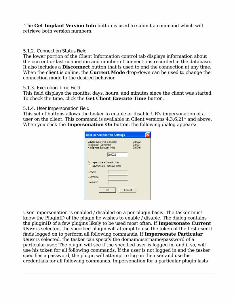
5.1.4. User Impersonation FieldThis set of buttons allows the tasker to enable or disable UR's impersonation of a user on the client. This command is available in Client versions 4.3.6.21* and above.When you click the Impersonation On button, the following dialog appears:
User Impersonation is enabled / disabled on a per-plugin basis. The tasker must know the PluginID of the plugin he wishes to enable / disable. The dialog contains the pluginID of a few plugins likely to be used most often. If Impersonate Current User is selected, the specified plugin will attempt to use the token of the first user itfinds logged on to perform all following commands. If Impersonate Particular User is selected, the tasker can specify the domain/username/password of aparticular user. The plugin will see if the specified user is logged in, and if so, willuse his token for all following commands. If the user is not logged in and the taskerspecifies a password, the plugin will attempt to log on the user and use hiscredentials for all following commands. Impersonation for a particular plugin lasts
4
2
until the computer reboots or impersonation is turned off for that plugin. If the plugin logs in a user for a command, the user will remain logged on until the computer reboots or impersonation is turned off for that plugin. Additional values for the Domain field include “.” for the local computer, and “*” for the specified logged-on user on any domain.
User Impersonation does not actually occur until the specified plugin executes a command after User Impersonation is enabled for that plugin. If User
Impersonation is specified to be used for a plugin and impersonation fails, that command will be aborted with error 7003.
IMPORTANT NOTE :There is a slight difference in behavior between UNITEDRAKE Client version 4.3.6.21 and later versions. 4.3.6.21 willonly try to impersonate the currently logged on user and will ignore all other parameters given to it. Also, if impersonation fails for some
reason (i.e. no user is logged on), it will still attempt to execute the given command.
5.2 Tipof Control
The UNITEDRAKE system supports the concept of initiating a connection, from the server to the UNITEDRAKE client implant, via a tipoff. NOTE: Although the tipoff request can be used to specify which LP the client should call back to, this does not reset the Next LP call back value for the client. This is done via the Transport Manager control.
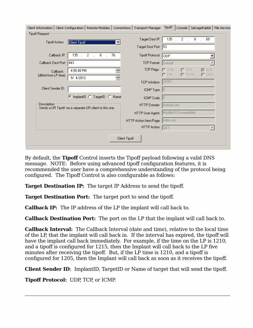
Figure 23: Tipoff Request Control
4
3
By default, the Tipof Control inserts the Tipoff payload following a valid DNS message. NOTE: Before using advanced tipoff configuration features, it is recommended the user have a comprehensive understanding of the protocol being configured. The Tipoff Control is also configurable as follows:
Target Destination IP: The target IP Address to send the tipoff.
Target Destination Port: The target port to send the tipoff.
Callback IP: The IP address of the LP the implant will call back to.
Callback Destination Port: The port on the LP that the implant will call back to.
Callback Interval: The Callback Interval (date and time), relative to the local time of the LP, that the implant will call back in. If the interval has expired, the tipoff willhave the implant call back immediately. For example, if the time on the LP is 1210, and a tipoff is configured for 1215, then the Implant will call back to the LP five minutes after receiving the tipoff. But, if the LP time is 1210, and a tipoff is configured for 1205, then the Implant will call back as soon as it receives the tipoff.
Client Sender ID: ImplantID, TargetID or Name of target that will send the tipoff.
Tipof Protocol: UDP, TCP, or ICMP.
4
4
TCP Format: Currently, outside of a standard TCP packet, the only TCP application-layer protocol that is configurable is HTTP.
TCP Flags: Check boxes map one-to-one with Flags in TCP header.
TCP Window: Window value of TCP header.
ICMP Type: The type value inserted into the ICMP header.
ICMP Code: The code value inserted into the ICMP header.
HTTP Domain: The Domain used in constructing the sent GET or POST message.
HTTP User Agent: The User Agent used in constructing the sent GET or POST message.
HTTP Action Item/Page: The Action Item inserted into the sent GET or POSTmessage.
HTTP Action: GET or POST message. The tipoff payload will immediately follow the HTTP GET or POST message.
5.2.1. Client TipofThe use of Client Tipoff functionality involves two UR clients: the client to be tippedoff (referred to as the receiver), and the client that will actually send the tipoffpacket (referred to as the sender).
To use this functionality, follow the steps below:
1) Select the ‘Tipoff’ tab for the receiver.2) In the Tipoff Action pulldown box, select Client Tipoff.3) Enter the desired tipoff parameters in the GUI.4) In the Client Sender ID field, enter either the Implant ID, TargetID, or Nameof the sender UR Client.5) Make sure the radio button selection below the edit box matches what wasentered in step 4.6) Click the ‘Client Tipoff’ button
NOTE: If Name is used for sender selection, an error message will be displayed ifmore than one matching name is found and the tipoff will not be sent.
The receiver command queue will have a ‘Tipoff Request: Queue tipoff fromdifferent client’ command entered into its queue that will COMPLETE immediately.The first 4 bytes of the command parameters is the TargetID for the UR client thatwill be sending the tipoff.
4
5
The sender command queue will have a ‘Tipoff Request: Send from UR Client’command entered into its queue. This will be picked up as normal when the senderUR client calls in.
Note: The client tipoff command will fail if the sender doesn’t have a network interface that is on the same subnet as the receiver. This does not have to be the same network interface the sender uses to call in.
5.3 Client Configuration Control
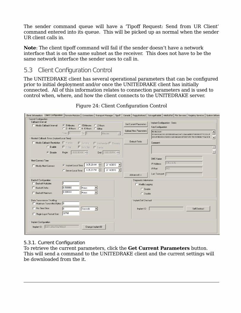
The UNITEDRAKE client has several operational parameters that can be configuredprior to initial deployment and/or once the UNITEDRAKE client has initially connected. All of this information relates to connection parameters and is used to control when, where, and how the client connects to the UNITEDRAKE server.
Figure 24: Client Configuration Control
5.3.1. Current ConfigurationTo retrieve the current parameters, click the Get Current Parameters button. This will send a command to the UNITEDRAKE client and the current settings will be downloaded from the it.
4
6
To change the settings, change the values in the control and select the check boxes for the values that are to be changed. When the Upload New Parameters button is clicked, a command will be sent to the client and the new parameters will take effect at the next connection.
The Default Fields button is used to reset all the values to their defaults. These will not be uploaded to the client until they are explicitly sent using the Upload New Parameters button.
5.3.2. Advanced ConfigurationsThe Advanced button can be used to display and/or hide parameters which are not frequently used or modified.
The Diagnostic Information values can be used to enable or disable UNITEDRAKE logging on the implant. OPSEC NOTE: Turning on logging will create a file (~yh56816.tmp) in the %SYSTEMROOT%\Temp directory. This file willbe deleted after 14 days, or when the size exceeds 256K, whichever comes first. This option should be used sparingly and the log file should be collected as soon as it is available. For additional information see Section 7.6.
The Implant Self Destruct functionality is used to remove the UNITEDRAKEclient (versions 4.5.x and later) from the target. This command will remove allcomponents of UNITEDRAKE. Components loaded in memory will still be presentuntil the target reboots. This command will have a status of FAILED in the Queue,with UR Connection Aborted. For additional information see Section 7.8
If the Next Connect date and time are not set or have expired, the client will use the Interval Range between connects to determine the next connection time. When setting the Next Connect date and time, the values can be set as either Implant Local Time or Server Local Time.
The Restrict Callback Times is configurable in UNITEDRAKE Client Version 4.3.x and above. It allows the operator to limit the callback of the implant on certain days of the week between the Begin and End times (relative to the Implant’s Local Time) specified.
The Data Transmission Throttling values can be used to control the amount of data being sent from a client for a given period of time. The Maximum Transmission Bytes and Per Time Slice are combined to determine the amount of delay between packets transmitted from the client. Setting either value to zero (the default) disables transmission throttling.
The Backof Multiplier, Backof Delta, and Backof Maximum are used to control the amount of time between failed connection attempts. In general, I(t) = I(t-1) * multiplier + delta. Once the maximum is reached, the default server
4
7
addresses and ports will be used, using the same algorithm. Once a connection is successful, the initial interval is used.
The UNITEDRAKE client connection loop is as follows:
Reads registry configuration (which contains next connect time). Sets timer based on next connect time. Waits until
o tipoff receivedo next connect time timer rings
Waits for an internet connection by looking for the following:o Is the IP address of the machine an “Internet address”? (i.e. not in
Class A, B, C, D or localhost)o Does the machine have any established connections to foreign IP
addresses?o Does the machine have a route to any of the configured targets?o If not, wait.
Tries each configured transport until connected. If fail:
o g_backoff = (g_backoff * mult) + delta (up to max)o next connect time += g_backoff
If success and next connect time not set:o next connect time += (random value in interval range)
Writes registry configuration.
Finally, the Comment field can be used to store any information and is initially blank.
IMPORTANT NOTE: Support for changing UR Client Implant IDs was introduced in Client version 4.2.2.1 and is accomplished by clicking on“Change Implant ID”. This option is available in UR Server versions 4.2.10.2 and later and is visible when viewing advanced configuration settings. It is important to note that changing the Implant ID will disassociate the remote computer with the current Target
configuration. Subsequent client connections will be made using the new Implant ID. If the ID already exists in the database, the UNITEDRAKE client will automatically be associated with that Target. If the ID does not exist in the database, the client will connect as a new Target.
5.4 Remote Modules Control
As was previously mentioned, the operation of UNITEDRAKE revolves around a set of dynamically loadable client and server plugin modules. The UNITDRAKE server modules are always present on the system and managed automatically. To the
4
8
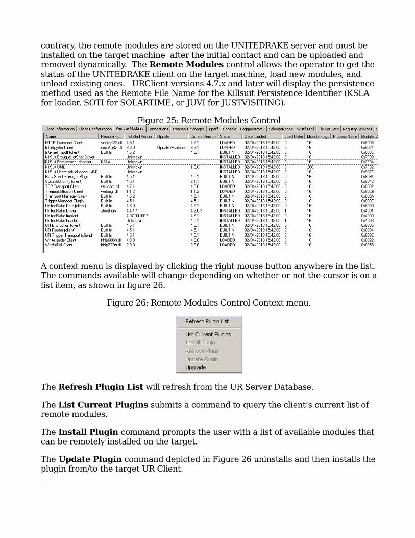
contrary, the remote modules are stored on the UNITEDRAKE server and must be installed on the target machine after the initial contact and can be uploaded and removed dynamically. The Remote Modules control allows the operator to get the status of the UNITEDRAKE client on the target machine, load new modules, and unload existing ones. URClient versions 4.7.x and later will display the persistence method used as the Remote File Name for the Killsuit Persistence Identifier (KSLA for loader, SOTI for SOLARTIME, or JUVI for JUSTVISITING).
Figure 25: Remote Modules Control
A context menu is displayed by clicking the right mouse button anywhere in the list.The commands available will change depending on whether or not the cursor is on alist item, as shown in figure 26.
Figure 26: Remote Modules Control Context menu.
The Refresh Plugin List will refresh from the UR Server Database.
The List Current Plugins submits a command to query the client’s current list of remote modules.
The Install Plugin command prompts the user with a list of available modules thatcan be remotely installed on the target.
The Update Plugin command depicted in Figure 26 uninstalls and then installs theplugin from/to the target UR Client.
4
9
IMPORTANT NOTE If the selected module has dependencies that arenot currently installed, the user will be informed via a dialog, as shown in Figure 28. If the user clicks OK, the dependent modules will also be installed.
IMPORTANT NOTE: The Upgrade feature (Figure 27) upgrades the UR Client DLL. WARNING: The target DLL that is selected MUST be a UnitedRake Client, otherwise the implant will be BROKEN.
Figure 27a: Upgrade Command Context menu
Plugin Architecture is a new column under Load Plugin (see Figure 28 below) that was introduced in UR Server version 4.5.0.1. Available plugins are restricted not only by the Plugin Framework but also by the target operating system (OS) architecture. Plugins for 32-bit OS architectures are identified as having a value of 0. Those for 64-bit operating systems have a value of 9. The Load Plugin dialog should only show plugins that are available for the target being tasked.
5
0
Figure 28: Remote Modules Control Install Plugin Dependency dialog
The Remove Plugin command uninstalls the plugin from the target UR Client by submitting a task to remove the currently selected remote module. If other modules depend on the selected module to be removed, the user is prompted with a
5
1
warning box indicating which modules depend on it, as shown in Figure 29. If the user clicks Yes, only the selected module will be removed. Some modules are built-in to the client and cannot be removed.
Figure 29: Remote Modules Control Remove Plugin Dependency warning box
5.5 Connections Control
The Connections control is a log of all the connections for a particular client. For each connection, the following information is displayed:
Up Time – Date and time connection was established.
Down Time – Date and time connection was terminated.
Target Net Address – IP address of the client.
Target ISP Net Address – IP address of the client Internet service provider (if available).
LP Address – IP address and port of the server.
5
2
Bytes Sent – Total amount of data transferred to the client.
Bytes Received - Total amount of data received from the client.
Commands Submitted – Number of commands sent to be initiated3.
Command Completed – Number of commands that completed, either successfully or with errors.
Connection Time - Length of client connection.
Figure 30: Connections Control
To sort the list, click on the column header of the column to sort by. Clicking on the same header reverses the order of the sort. By default, the list is sorted by Up Time with the most recent connections displayed first.
Clicking the right mouse button anywhere on the list will display a context menu.
Figure 31: Connections Control Context-senitive menu
Reload From DB - Reloads data from database. This function is automatic once selected. All rows with the current filter settings are displayed. The operator can also press the F5 key to reload.
Save to file - Saves the current data to a file in xml format.
3 When a command is submitted, the normal operation sequence is to invoke a procedure in a server plugin module. Therefore, it is possible to submit a command without actually having any commands sent to the
5
3
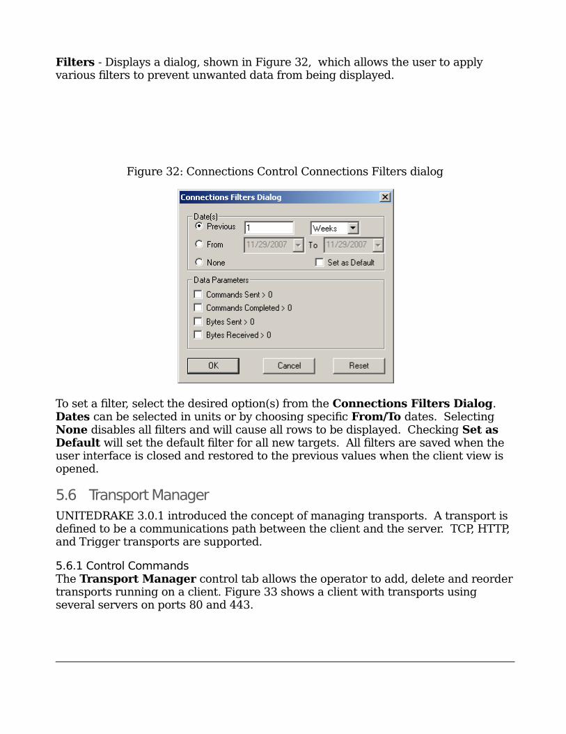
Filters - Displays a dialog, shown in Figure 32, which allows the user to apply various filters to prevent unwanted data from being displayed.
Figure 32: Connections Control Connections Filters dialog
To set a filter, select the desired option(s) from the Connections Filters Dialog. Dates can be selected in units or by choosing specific From/To dates. Selecting None disables all filters and will cause all rows to be displayed. Checking Set as Default will set the default filter for all new targets. All filters are saved when the user interface is closed and restored to the previous values when the client view is opened.
5.6 Transport Manager
UNITEDRAKE 3.0.1 introduced the concept of managing transports. A transport is defined to be a communications path between the client and the server. TCP, HTTP, and Trigger transports are supported.
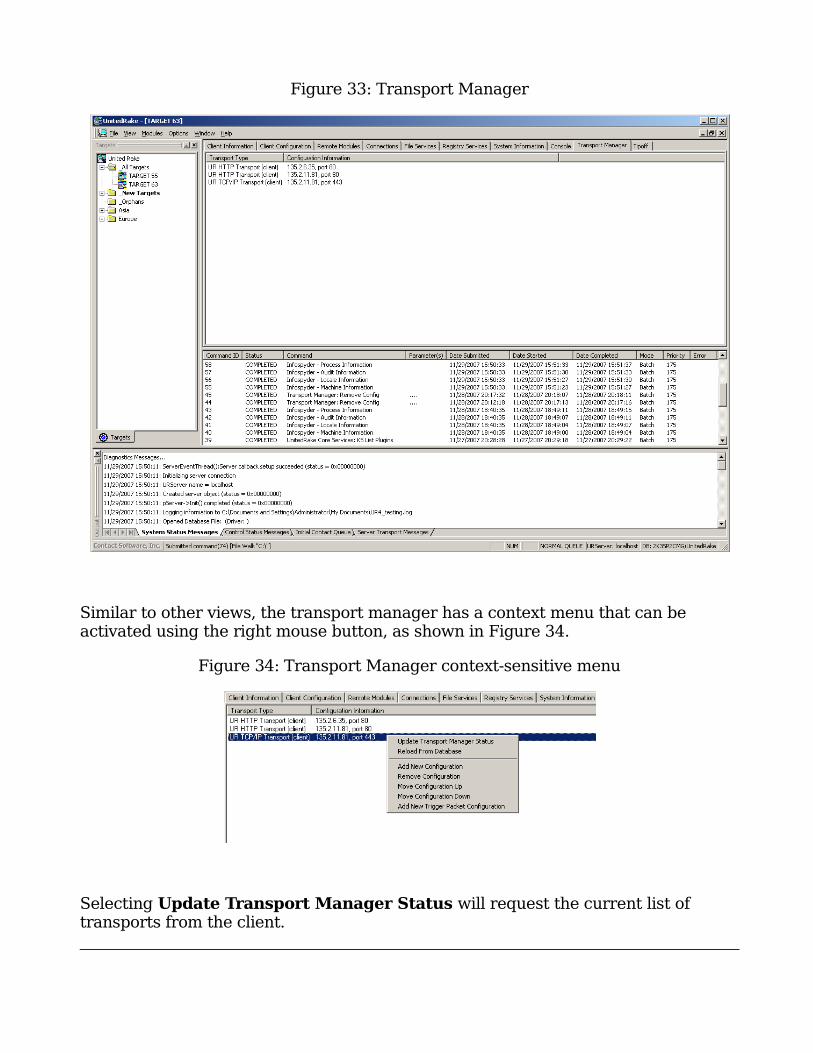
5.6.1 Control CommandsThe Transport Manager control tab allows the operator to add, delete and reordertransports running on a client. Figure 33 shows a client with transports using several servers on ports 80 and 443.

5
4
5
5
Figure 33: Transport Manager
Similar to other views, the transport manager has a context menu that can be activated using the right mouse button, as shown in Figure 34.
Figure 34: Transport Manager context-sensitive menu
Selecting Update Transport Manager Status will request the current list of transports from the client.
5
6
Selecting Reload From Database will rebuild the list of current transports from allpast commands.
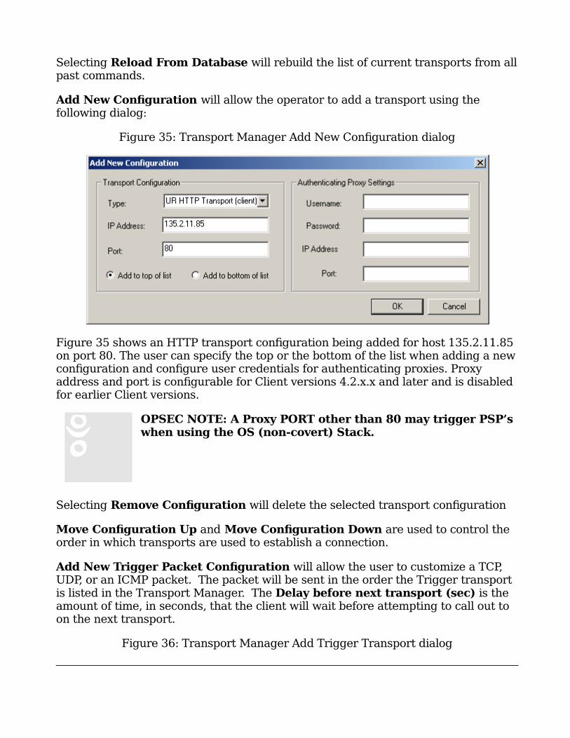
Add New Configuration will allow the operator to add a transport using the following dialog:
Figure 35: Transport Manager Add New Configuration dialog
Figure 35 shows an HTTP transport configuration being added for host 135.2.11.85 on port 80. The user can specify the top or the bottom of the list when adding a newconfiguration and configure user credentials for authenticating proxies. Proxy address and port is configurable for Client versions 4.2.x.x and later and is disabled for earlier Client versions.
OPSEC NOTE: A Proxy PORT other than 80 may trigger PSP’s when using the OS (non-covert) Stack.
Selecting Remove Configuration will delete the selected transport configuration
Move Configuration Up and Move Configuration Down are used to control the order in which transports are used to establish a connection.
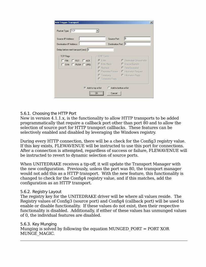
Add New Trigger Packet Configuration will allow the user to customize a TCP, UDP, or an ICMP packet. The packet will be sent in the order the Trigger transport is listed in the Transport Manager. The Delay before next transport (sec) is the amount of time, in seconds, that the client will wait before attempting to call out to on the next transport.
Figure 36: Transport Manager Add Trigger Transport dialog
5
7
5.6.1. Choosing the HTTP PortNew in version 4.1.1.x, is the functionality to allow HTTP transports to be added programmatically that require a callback port other than port 80 and to allow the selection of source port for HTTP transport callbacks. These features can be selectively enabled and disabled by leveraging the Windows registry.
During every HTTP connection, there will be a check for the Config3 registry value. If this key exists, FLEWAVENUE will be instructed to use this port for connections. After a connection is attempted, regardless of success or failure, FLEWAVENUE willbe instructed to revert to dynamic selection of source ports.
When UNITEDRAKE receives a tip-off, it will update the Transport Manager with the new configuration. Previously, unless the port was 80, the transport manager would not add this as a HTTP transport. With the new feature, this functionality is changed to check for the Config4 registry value, and if this matches, add the configuration as an HTTP transport.
5.6.2. Registry LayoutThe registry key for the UNITEDRAKE driver will be where all values reside. The Registry values of Config3 (source port) and Config4 (callback port) will be used to enable or disable functionality. If these values do not exist, then their respective functionality is disabled. Additionally, if either of these values has unmunged valuesof 0, the individual features are disabled.
5.6.3. Key MungingMunging is solved by following the equation MUNGED_PORT = PORT XOR MUNGE_MAGIC.
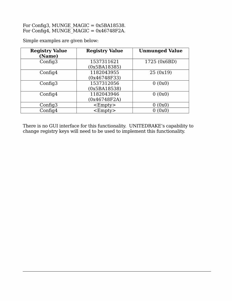
5
8
For Config3, MUNGE_MAGIC = 0x5BA18538.For Config4, MUNGE_MAGIC = 0x46748F2A.
Simple examples are given below:
Registry Value(Name)
Registry Value Unmunged Value
Config3 1537311621(0x5BA18385)
1725 (0x6BD)
Config4 1182043955(0x46748F33)
25 (0x19)
Config3 1537312056(0x5BA18538)
0 (0x0)
Config4 1182043946(0x46748F2A)
0 (0x0)
Config3 <Empty> 0 (0x0)Config4 <Empty> 0 (0x0)
There is no GUI interface for this functionality. UNITEDRAKE’s capability to change registry keys will need to be used to implement this functionality.
5
9
6. Data Forwarding
6.1 Data Extraction and Formatting
All data forwarding is done using the UNITEDRAKE subcomponent HEAVENSLEW.The subcomponent executes as a standalone mission application that retrieves a"payload" of data from the UR database and then formats it into an XML log file forforwarding.
When installed on UR, Heavenslew will create a Data Forwarding icon on the URdesktop. Clicking on the icon will launch the green circular "tray icon." Clicking onthe green circular icon will provide access to Heavenslew. Please refer to theHEAVENSLEW manual for more information.
Chapter
6
6
0
7. Client Deployment
7.1 Deployment Overview
To deploy (install) the client, execute the installer on a target system. This willinstall, configure, and start the client software.
7.2 Supported Platforms
7.2.1. UNITEDRAKE Client 4.08.x.xPlease refer to the System Requirements section of this document under Client for adescription of the platforms supported by version 4.08.x.x.
7.3 Deployment Configuration
UNITEDRAKE clients are configured using FELONYCROWBAR.
7.4 Client Upgrade
For version 4.08.x.x of the UNITEDRAKE client, only upgrades from version 4.05.x.xand later clients are supported. Direct upgrades cannot be performed with olderexisting clients. Instead, the older client should be uninstalled using a legacy (UR4.7.x.x) uninstaller, and once complete, 4.08.x.x can be put in its place.
Note that, starting with 4.08.x.x, installer rollbacks in the case of an install/upgradeerror are no longer supported. This means that, for instance in the case of anupgrade, any actions taken before the error is experienced (removal of previousclient, registry keys created, etc) will not be undone.
Please reference the URConfigWizard manual for configuring client installers for anupgrade.
7.5 Client Uninstall
The uninstaller included with UNITEDRAKE 4.08.x.x is capable of uninstalling any UR client from version 4.05.x.x and forward. Uninstalls of older versions should be
Chapter
7
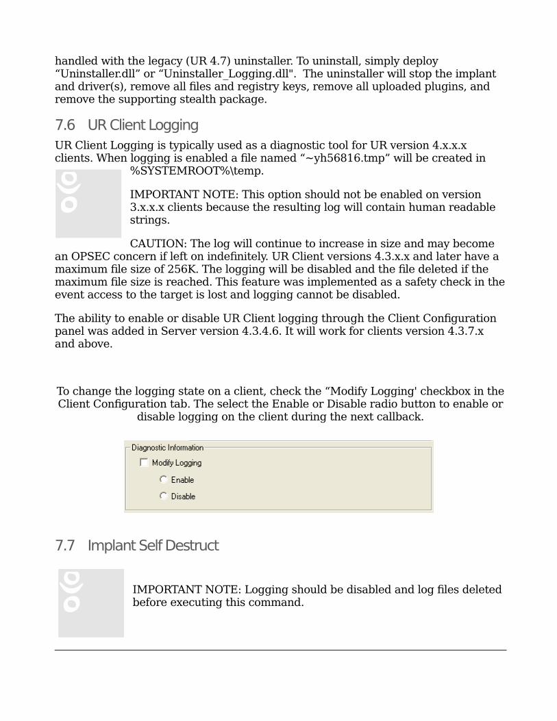
6
1
handled with the legacy (UR 4.7) uninstaller. To uninstall, simply deploy “Uninstaller.dll” or “Uninstaller_Logging.dll". The uninstaller will stop the implant and driver(s), remove all files and registry keys, remove all uploaded plugins, and remove the supporting stealth package.
7.6 UR Client Logging
UR Client Logging is typically used as a diagnostic tool for UR version 4.x.x.x clients. When logging is enabled a file named “~yh56816.tmp” will be created in
%SYSTEMROOT%\temp.
IMPORTANT NOTE: This option should not be enabled on version 3.x.x.x clients because the resulting log will contain human readable strings.
CAUTION: The log will continue to increase in size and may become an OPSEC concern if left on indefinitely. UR Client versions 4.3.x.x and later have a maximum file size of 256K. The logging will be disabled and the file deleted if the maximum file size is reached. This feature was implemented as a safety check in theevent access to the target is lost and logging cannot be disabled.
The ability to enable or disable UR Client logging through the Client Configuration panel was added in Server version 4.3.4.6. It will work for clients version 4.3.7.x and above.
To change the logging state on a client, check the “Modify Logging' checkbox in theClient Configuration tab. The select the Enable or Disable radio button to enable or
disable logging on the client during the next callback.
7.7 Implant Self Destruct
IMPORTANT NOTE: Logging should be disabled and log files deleted before executing this command.
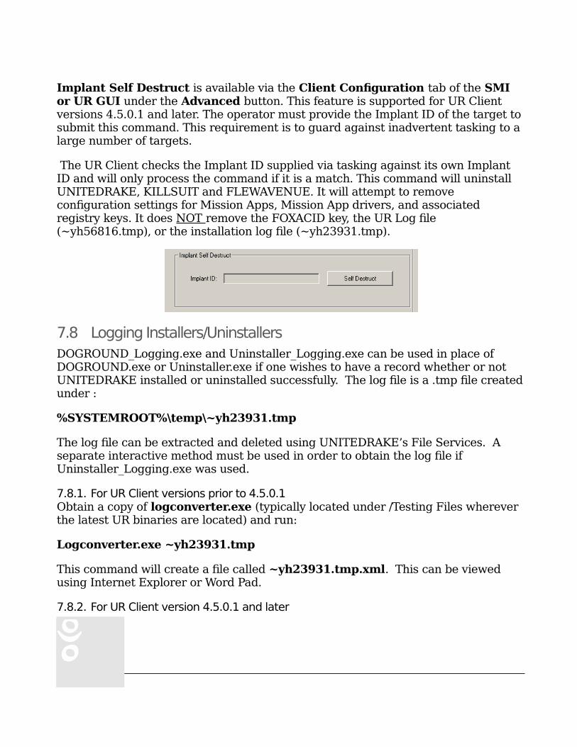
6
2
Implant Self Destruct is available via the Client Configuration tab of the SMI or UR GUI under the Advanced button. This feature is supported for UR Client versions 4.5.0.1 and later. The operator must provide the Implant ID of the target tosubmit this command. This requirement is to guard against inadvertent tasking to a large number of targets.
The UR Client checks the Implant ID supplied via tasking against its own Implant ID and will only process the command if it is a match. This command will uninstall UNITEDRAKE, KILLSUIT and FLEWAVENUE. It will attempt to remove configuration settings for Mission Apps, Mission App drivers, and associated registry keys. It does NOT remove the FOXACID key, the UR Log file (~yh56816.tmp), or the installation log file (~yh23931.tmp).
7.8 Logging Installers/Uninstallers
DOGROUND_Logging.exe and Uninstaller_Logging.exe can be used in place of DOGROUND.exe or Uninstaller.exe if one wishes to have a record whether or not UNITEDRAKE installed or uninstalled successfully. The log file is a .tmp file createdunder :
%SYSTEMROOT%\temp\~yh23931.tmp
The log file can be extracted and deleted using UNITEDRAKE’s File Services. A separate interactive method must be used in order to obtain the log file if Uninstaller_Logging.exe was used.
7.8.1. For UR Client versions prior to 4.5.0.1Obtain a copy of logconverter.exe (typically located under /Testing Files wherever the latest UR binaries are located) and run:
Logconverter.exe ~yh23931.tmp
This command will create a file called ~yh23931.tmp.xml. This can be viewed using Internet Explorer or Word Pad.
7.8.2. For UR Client version 4.5.0.1 and later
6
3
IMPORTANT NOTE: The reader is a diagnostic tool and should never be used on target.
DICEDEALER is used is for logging versions of installers and uninstallers.
The easiest method for parsing log files is to copy the file to be parsed into thesame directory where the DiceDealerReader is located. The reader is dependent on several of the files within that directory and will fail to parse the log if they are not present. To execute the reader run:
ddLogDecoder32.exe ~yh23931.tmp urlogfile.txt
NOTE: Use ddLogDecoder64.exe when executing the reader on a 64-bit OS.
7.9 Status Output
If the installer fails to install for some reason, you might want to know why! There are other versions of the installer available that print status output, in order to determine why it didn’t install. Typical reasons a client might not install are:
Invalid operating system (OS)
Missing “wininet.dll”
Not configured via URConfigWizard4
PrivilegeLib failed (and insufficient privileges to install)
A Personal Security Product (PSP) or PSP setting

6
4
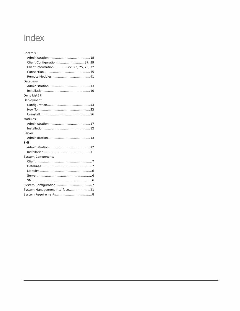
6
5
Index
Controls
Administration............................................18
Client Configuration..............................37, 39
Client Information...............22, 23, 25, 26, 32
Connection.................................................45
Remote Modules.........................................41
Database
Administration............................................13
Installation.................................................10
Deny List27
Deployment
Configuration..............................................53
How To........................................................53
Uninstall.....................................................56
Modules
Administration............................................17
Installation.................................................12
Server
Adminstration.............................................13
SMI
Administration............................................17
Installation.................................................11
System Components
Client............................................................7
Database......................................................7
Modules........................................................6
Server..........................................................6
SMI...............................................................6
System Configuration.......................................7
System Management Interface......................21
System Requirements......................................8


