8


N.A. Woodworth’s comprehensive line of workholding begins with the “UBL”.It is “The Original” used industry wide and it sets the standard for all otherpower chucks.
The features of the UBL include:• Easy conversion from external to internal chucking• Positive pullback action• Chucks are internally lubricated and have a sealed design to keep
chips and contaminants out• Jaw homing device allows jaws to compensate for part variations• Various jaws for different work pieces can be readily interchanged• Offered in Centralizing and Compensating• Centralizing chucks put the work piece on the center rotation• Compensating chucks enable the actuator to float and allow the chuck
jaws to engage independently of the chuck center
Universal Ball-Lok (UBL) Chuck
Recommended Chucking Ranges
Internal ModeExternal Mode
All sizes are in millimeters.
The above recommended chucking ranges are for general applications. Ifan application has a part size that exceeds the above maximum orminimum, contact the Woodworth proposal department for review.
“A” Diameter “B” DiameterExternal Chucking Range Internal Chucking Range
(Recommended) (Recommended)
maximum / minimum maximum / minimum
160 120 / 14 150 / 70
200 150 / 16 200 / 80
250 200 / 50 230 / 85
300 240 / 65 300 / 130
380 315 / 80 380 / 165
460 390 / 90 455 / 245
UB
LS
ize
— 2 —

Features
Internal and External clamping modes.
To change from OD clamping to ID clamping:A. Remove 4 bolts from each front bearing.B. Rotate actuator arm 180 degrees (without removing
from the chuck body).C. Replace and tighten front bolts.
Ability to grip shorter lengths and tapereddiameters.
Extended life.
Positive pull-back action.
Clamp Unclamp ➞➞➞➞
A flat is provided at the center of the spherical diameter.This flat is what enables the pull-back feature. The flat isstandard in our bearings, or can be customized forspecific needs.
Homing function of jaws.
“Homing” is the ability of the jaws to rotate up to 5degrees in either direction. “Homing” allows the jaws tocompensate for castings and forgings that are notperfectly round and insures secure and equalizedgripping force at all chucking points.
UBL chucks can grip work-pieces having up to a 7 degreetaper. With standard jaw design and up to 12 degreeswith minor modifications.
Master jaw develops lift
Abrasion between themaster jaw and cross slide
The life of a standard, sliding jaw, power chuck is greatlyreduced by abrasion between the master jaws and chuckbody. Over time the base jaws will develop lift.
The UBL chucks utilize a spherical ball and bearingdesign which reduces wear, thus extending the life of thechuck.
Component inter-changeability.
UBL components are designed and manufactured forinter-changeability. Replacement components can beeasily installed; maintaining the original accuracies.
Components are in stock and can be promptly delivered.
— 3 —

— 4 —
Centralizing Type
Centralizing UBL Chucks work by utilizing a one-piece actuator device which allowsthe chuck jaws to establish the axis of rotation. The diameters being turned will thenbe concentric to the chucking diameter. The pull back feature insures the work pieceis against an axial locator which guarantees perpendicularity and parallelism.
Practical Examples
ROTORS GEARS TAPERED WORK PIECES EXTENDED WORK PIECES
Compensating Type
Compensating UBL chucks work by utilizing a two piece actuator device which allowsthe chuck jaws to compensate for any eccentricity between the chucking diameter andthe datum diameter. The centralizing device is generally an arbor, plug or centermounted on the face of the chuck. The centralizing device establishes the axis of rotationfrom the datum diameter in the work piece. The diameters being turned will then beconcentric to the datum diameter.
Practical ExamplesClamping of cast surfacewhile locating the part bymeans of a Tork-Lok arbor
Clamping of cast surfacewhile locating the part bymeans of a plug
Clamping of work-pieceheld between (2) centers

Chuck Size
— 5 —
Specifications
1 KN = 224.81 lbs. (Force)1 kg = 2.20 lbs. (Weight)
CENTRALIZING(2/Jaw) Model Number(3/Jaw) Model Number
COMPENSATING(2/Jaw) Model Number(3/Jaw) Model Number
Dimensions (mm)Chuck DiameterMounting Recess Dia.Depth of RecessChuck HeightBack Plate Boss Dia.Actuator Dia.Draw Bar ThreadActuator PositionChuck Mounting Bolt SizeLength of BossMounting Bolt Circle Dia.Actuator Stroke to Full CloseActuator Stroke to Full OpenTotal Actuator StrokeJaw Mounting PlatformJaw Ledge (External Grip)Jaw Ledge (Internal Grip)Jaw Mounting Screw SizeTooling Mounting Screw SizePosition of “T” (3) JawPosition of “T” (3) JawPosition of “T” (3) JawPosition of “T” (3) JawPosition of “T” (3) JawPosition of “T” (2) JawPosition of “T” (2) JawPosition of “T” (2) JawPosition of “T” (2) JawPosition of “T” (2) JawPosition of “T” (2) JawMaximum drawbar force (2) Jaw (KN)Maximum static gripping force (2) Jaw (KN)Maximum drawbar force (3) Jaw (KN)Maximum static gripping force (3) Jaw (KN)Maximum RPMJaw Weight (kg)Chuck Weight (kg)
ABCDEFGHJKLMN
M+NPQRSTUVWXYZ
AAABACADAE
160
UBL160010UBL160000
UBL160012UBL160002
1601408.7
72.242
30.2M16 x 2
23.5M10 x 1.5
6.8104.85.26.411.619.4
73.0322.23
M10 x 1.5M8 x 1.25
N/AN/A35
N/A708040
N/AN/A85
17017422664
55001.0711.34
200
UBL200010UBL200000
UBL200012UBL200002
2001708.7
84.245
31.8M16 x 2
25.1M12 x 1.75
11.1133.4
86.3
14.323.788.925.4
M12 x 1.75M8 x 1.25
N/AN/A50
N/A87.51005035
17.5N/AN/A26643585
42001.87
24.95
250
UBL250010UBL250000
UBL250012UBL250002
254.12208.7
103.257.241.3
M20 x 2.528
M16 x 28.7
171.47.99.7
17.629.2112.730.14
M16 x 2M10 X 1.5
502560
97.5N/A12562.545
22.5N/AN/A3175
44.5108
36003.09
38.56
300
UBL300010UBL300000
UBL300012UBL300002
298.62208.7
103.260
41.3M20 x 2.5
28M16 x 2
8.7171.47.99.8
17.729.2
133.3550.81
M16 x 2M10 x 1.5
502560
100N/A210105904565
13035.58653
13032003.77
54.43
380
UBL380010UBL380000
UBL380012UBL380002
38130014.3116.7
8557.15
M24 x 338.7
M20 x 2.516
23510.411.922.332.5
171.4569.85
M20 x 2.5M12 x 1.75
N/AN/A82.5N/A
152.515075
10050
N/AN/A44
10766160
26005.87
117.93
460
UBL460010UBL460000
UBL460012UBL460002
457.338013.5116.7
120.6588.9
M24 x 328
M24 x 38.7
330.210.411.922.332.5
209.55103.95
M20 x 2.5M16 x 2
N/AN/A110N/A200200100200100N/AN/A44
10766
16021007.26
145.15
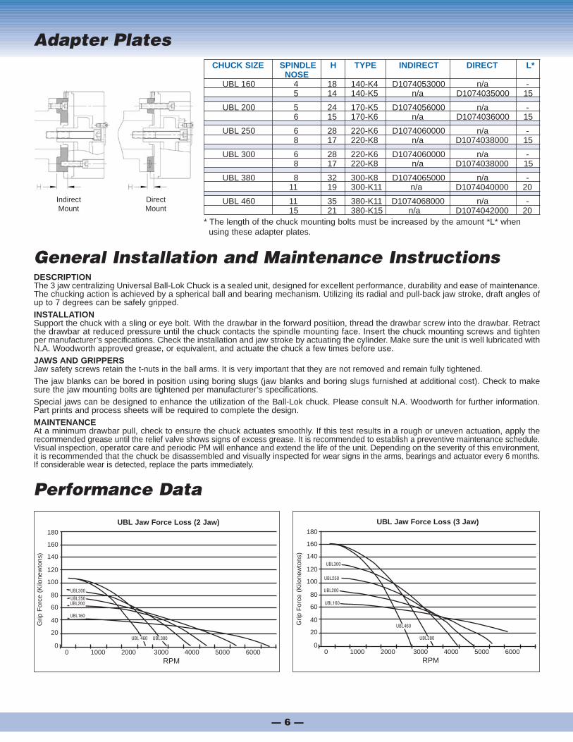
Adapter Plates
Performance Data
General Installation and Maintenance InstructionsDESCRIPTIONThe 3 jaw centralizing Universal Ball-Lok Chuck is a sealed unit, designed for excellent performance, durability and ease of maintenance.The chucking action is achieved by a spherical ball and bearing mechanism. Utilizing its radial and pull-back jaw stroke, draft angles ofup to 7 degrees can be safely gripped.INSTALLATIONSupport the chuck with a sling or eye bolt. With the drawbar in the forward positiion, thread the drawbar screw into the drawbar. Retractthe drawbar at reduced pressure until the chuck contacts the spindle mounting face. Insert the chuck mounting screws and tightenper manufacturer’s specifications. Check the installation and jaw stroke by actuating the cylinder. Make sure the unit is well lubricated withN.A. Woodworth approved grease, or equivalent, and actuate the chuck a few times before use.JAWS AND GRIPPERSJaw safety screws retain the t-nuts in the ball arms. It is very important that they are not removed and remain fully tightened.The jaw blanks can be bored in position using boring slugs (jaw blanks and boring slugs furnished at additional cost). Check to makesure the jaw mounting bolts are tightened per manufacturer’s specifications.Special jaws can be designed to enhance the utilization of the Ball-Lok chuck. Please consult N.A. Woodworth for further information.Part prints and process sheets will be required to complete the design.MAINTENANCEAt a minimum drawbar pull, check to ensure the chuck actuates smoothly. If this test results in a rough or uneven actuation, apply therecommended grease until the relief valve shows signs of excess grease. It is recommended to establish a preventive maintenance schedule.Visual inspection, operator care and periodic PM will enhance and extend the life of the unit. Depending on the severity of this environment,it is recommended that the chuck be disassembled and visually inspected for wear signs in the arms, bearings and actuator every 6 months.If considerable wear is detected, replace the parts immediately.
CHUCK SIZE SPINDLE H TYPE INDIRECT DIRECT L*NOSE
UBL 160 4 18 140-K4 D1074053000 n/a -5 14 140-K5 n/a D1074035000 15
UBL 200 5 24 170-K5 D1074056000 n/a -6 15 170-K6 n/a D1074036000 15
UBL 250 6 28 220-K6 D1074060000 n/a -8 17 220-K8 n/a D1074038000 15
UBL 300 6 28 220-K6 D1074060000 n/a -8 17 220-K8 n/a D1074038000 15
UBL 380 8 32 300-K8 D1074065000 n/a -11 19 300-K11 n/a D1074040000 20
UBL 460 11 35 380-K11 D1074068000 n/a -15 21 380-K15 n/a D1074042000 20
* The length of the chuck mounting bolts must be increased by the amount *L* when using these adapter plates.
— 6 —
0 1000 2000 3000 4000 5000 6000RPM
180
160
140
120
100
80
60
40
20
0
Grip
For
ce (
Kilo
new
tons
)
UBL Jaw Force Loss (2 Jaw)
UBL300
UBL250UBL200
UBL160
UBL 460 UBL380
0 1000 2000 3000 4000 5000 6000RPM
180
160
140
120
100
80
60
40
20
0
Grip
For
ce (
Kilo
new
tons
)
UBL Jaw Force Loss (3 Jaw)
UBL460
UBL380
UBL300
UBL250
UBL200
UBL160
IndirectMount
DirectMount

Component Parts / Service Kits
Included in Kit NumbersDescription 1 2 3 4 5 6
B Retaining Ring 1C Retaining Spacer 1E Centralizing Pin 3H Eccentric Bearing 3J Spring Cap 3 1K Arm Spring 3 1L Arm Key 3 3 1M Homing Spring 3 1N Restrictor Pin 3 1O Homing Pin 6 2P T-Nut 3Q Safety Screw 3S Jaw Bolts 6T Arm 1U Arm Seal 3 1 3V Front Bearing 1 3X Grease Fitting 4Y Relief Valve 1
A Floating Actuator Purchase SeparatelyD Actuator Support Purchase SeparatelyF Plain Back Adapter Purchase SeparatelyG Actuator Purchase SeparatelyI Housing Purchase SeparatelyR Jaw Blank Purchase SeparatelyW Dust Cover Purchase Separately
Solid Carbide Inserts for Chuck Jaws• REPLACEABLE• INCREASE LIFE OF TOP JAWS• REDUCE CHUCK JAW INVENTORY
Install these rapid-change, long-life inserts in your chuck jaws. After an extensiveperiod of maintenance-free service, inserts can be easily and quickly replaced withoutthe necessity of costly down-time.
Both styles offer positive gripping on rough or smooth surfaces of castings, forging, etc.
Angle-Lok inserts offer additional advantages - permit tools to come closer to the top ofthe jaws and provides clamping on narrow chucking land.
Angle-Lok style
Round style
See Insert Catalog for additiionalstyles and sizes
HARDWARE ECC. BEARING ARM (02)* TEE-NUT FRONT BEARING* COMP. JAW BLANK
Kit Number 1 2 3 4 5 6160 UBL160HK UBL06BK UBL1602AK UBL160TN UBL1602BK UBL06CK UBL-6801-B200 UBL200HK UBL08BK UBL2002AK UBL200TN UBL2002BK UBL200CK UBL-8801-B250 UBL250HK UBL10BK UBL2502AK UBL250TN UBL2502BK UBL250CK UBL-10801-B300 UBL250HK UBL10BK UBL2502AK UBL250TN UBL2502BK UBL250CK UBL-12801-B380 UBL380HK UBL15BK UBL3802AK UBL380TN UBL3802BK UBL380CK UBL-15801-BM460 UBL380HK UBL15BK UBL3802AK UBL380TN UBL3802BK UBL380CK UBL-18801-BM
SERVICE KITS
*These kits are set up for use with our standard UBL chuck using standard pull-back bearings. Please specify if “non” pull-back bearings are required.U
BL
Size
— 7 —
A
BC
D
E
F
G H
I J
K
LM
N
O
P
Q
R
S
T
U
V
YX
W
CentralizingType
Compensating Type
3 ZL 200 E 0
4/15 0.0 FK Edition 12/11 Printed in Germany
FORKARDT GMBHLachenhauweg 1272766 Reutlingen-MittelstadtD-40699 ErkrathPhone: (+49) 211 25 06-0E-Mail: [email protected]
FORKARDT USA2155 Traversefield Drive Traverse City, MI 49686, USA Phone: (+1) 800 544-3823
(+1) 231 995-8300 Fax: (+1) 231 995-8361E-Mail: [email protected] Website: www.forkardt.com
FORKARDT FRANCE S.A.R.L.28 Avenue de BobignyF-93135 Noisy le Sec CédexPhone: (+33) 1 4183 1240Fax: (+33) 1 4840 4759E-Mail: [email protected]
FORKARDT CHINAPrecision Machinery (Shanghai) Co Ltd 1F, #45 Building, No. 209 Taigu Road, Waigaoqiao FTZ CHINA 200131, CHINAPhone: (+86) 21 5868 3677E-Mail: [email protected] Website: www.forkardt.com
FORKARDT INDIA LLPPlot No. 39 D.No.5-5-35Ayyanna Ind. ParkIE Prasanthnagar, KukatpallyHyderabad - 500 072IndiaPhone: (+91) 40 400 20571Fax: (+91) 40 400 20576E-Mail: [email protected]
www.forkardt.com
© 2015 FORKARDT, Errors and omissions excepted.
L O C A T I O N S W O R L D W I D E
Innovative Technology by
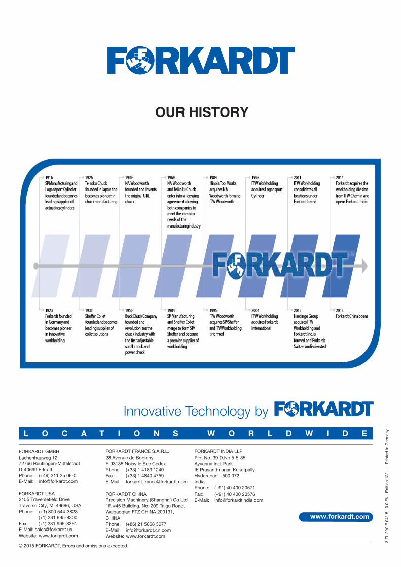
OUR HISTORY


![De-Centralizing Operations with APM [FutureStack16]](https://static.documents.pub/doc/80x56/5870d97f1a28ab64768b74ed/de-centralizing-operations-with-apm-futurestack16.jpg)


