23
Universal Hydraulic Steering Kit SmarTrax™ Installation Manual P/N 016-9001-008 Rev D 09/15 Copyright 2009, 2015
Universal Hydraulic Steering Kit
SmarTrax™ Installation Manual
P/N 016-9001-008 Rev D 09/15
Copyright 2009, 2015

While every effort has been made to ensure the accuracy of this document, Raven Industries assumes no responsibility for omissions and errors. Nor is any liability assumed for damages resulting from the use of information contained herein.
Raven Industries shall not be held responsible or liable for the effects of atmospheric conditions and sunspot activity on the performance of our products.
Raven Industries cannot guarantee the accuracy, integrity, continuity, or availability of the GPS signal from the U.S. Department of Defense/NAVSTAR GPS satellites, the OmniSTAR correction service or the WAAS correction service.
Raven Industries accepts no responsibility for the use of the signal for other than the stated purpose. Raven Industries shall not be responsible or liable for incidental or consequential damages or a loss of anticipated benefits or profits, work stoppage or loss or impairment of data arising out of the use, or inability to use, the SmarTrax or any of its components.
Disclaimer

Manual # 016-9001-008
1
C H A P T E R
1INTRODUCTION
About this Guide
The aim of this guide is to provide up to date reference information about installation ofSmarTrax.
Who is it for
This guide is intended for use by distributors who install new SmarTrax systems for RavenIndustries.
What it covers
This guide presents:
• a parts checklist for steering installation• installation procedures for SmarTrax hydraulic kit and cable routing
Updates
This guide will be updated periodically to reflect changes and additions to the range ofSmarTrax products and to ensure that this guide fulfills user’s needs for referenceinformation. Updates will be supplied as soon as they are available.

Univ. Hyd. Steering Kit Install Guid for Open Center Hydraulic Systems
2
Notes:

Manual # 016-9001-008
3
C H A P T E R
2SAFETY REQIUREMENTS
This section is divided between general safety precautions, specific safetymeasures for hydraulic and electrical system, and safety symbols used in thisdocument.
The machine must remain stationary and switched off, and SteeringAssistTM disengaged while installation or maintenance is being carriedout.
Safety Precautions
•When working with or near a machine with SmarTrax installed, the followingsafety measures must be observed. The operator must:
• Be alert and aware of surroundings.
• Avoid operating the SmarTrax while under the influence of alcohol or anilleagal substance.
• Remain in the operator’s positon at all times when SmarTrax is engaged.
• Be in complete control of machine at all times when SmarTrax isengaged.
• Remain with boundaries of a defined field when SmarTrax is engaged.
• Avoid driving the machine with SmarTrax engaged on any publicthoroughfare or main road.
• Determine and remain a safe working distance from other machinery,equipment, and obtacles. The operator is responsible for disengagingSmarTrax when safe working distance has dimished.

Univ. Hyd. Steering Kit Install Guid for Open Center Hydraulic Systems
4
• Dtermine and remain a safe working distance from other farm personnelor bystanders. The operator is responsible for disengaging SmarTraxwhen safe working distnace has dimished.
• Ensure SmarTrax is disengaged prior to starting any maintenance workon SmarTrax or machine.
Hydraulic Safety Precautions
When disconnecting hydraulic hoses or when purging is required, be aware thathydraulic oil may be hot and under high pressure. Caution must be exercised.
Any work carried out on the hydraulics system must be performed in accordancewith machine manufacturer’s approved maintenance instructions.
Raven Industries recommends that appropriate protective equipment be worn.
It is imperative that, during installation, diagnostics, maintenance, or routinemachine servicing, all precautions are taken to prevent foreigm material orcontaminants from being introduced into the hydraulic system.
Objects or materials that are able to bypass the machine’s hydraulic filtrationsystem will adversely reduce performance, and possible damage hydraulicvalves.
Electrical Safety Precautions
Do not reverse power leads. Doing so will cause severe damage to equipment.Always check to macke sure that power leads are connected to the correctpolarity as marked.
Ensure that power cable is the last cable to be connected.
Safety Symbols
WARNING: Identifies information about practives orcircumstances that can lead to personal injury or death, propertydamage or economic loss.
Warning statements help you:
• Identify a hazard• Avoid a hazard• Recognize consequences
NOTE: Identifies information that is critical for successfulapplication and understanding of the product.
WARNING
Manual # 016-9001-008
5
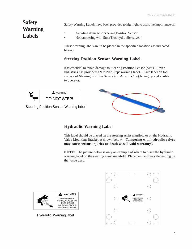
Safety Warning Labels have been provided to highlight to users the importance of:
• Avoiding damage to Steering Position Sensor• Not tampering with SmarTrax hydraulic valves
These warning labels are to be placed in the specified locations as indicatedbelow.
Steering Position Sensor Warning Label
It is essential to avoid damage to Steering Position Sensor (SPS). RavenIndustries has provided a ‘Do Not Step’ warning label. Place label on topsurface of Steering Position Sensor (as shown below) facing up and visibleto operator.
Hydraulic Warning Label
This label should be placed on the steering assist manifold or on the HydraulicValve Mounting Bracket as shown below. ‘Tampering with hydraulic valvesmay cause serious injuries or death & will void warranty’.
NOTE: The picture below is only an example of where to place the hydraulicwarning label on the steering assist manifold. Placement will vary depending onthe valve used.
Steering Position Sensor Warning label
Hydraulic Warning label
SafetyWarningLabels
Univ. Hyd. Steering Kit Install Guid for Open Center Hydraulic Systems
6
This section outlines the safety requirements used when driving a vehicle usingthe SmarTrax system.
Areas of Operation
SmarTrax must only be used on private property without public access and withincleared fields. It must NOT be used on any public roads or access ways. RavenIndustries advise that users familiarize themselves with SmarTrax operations byfirst reading the Machine Operator Guide.
Avoidance of People
The SmarTrax must not be operated in the vicinity of bystanders. Bystandersmust be well away from the machine’s path while it is operating with SmarTraxengaged.
Avoidance of Machinery and Equipment
The SmarTrax operator must allow a safe distance between the machine’s pathand other machinery or equipment. To determine a safe distance, considerpossible incorrect operation, loss of GPS and the distance required for themachine to stop.
Avoidance of Obstacles
SmarTrax CANNOT detect obstacles such as fences, trees or boulders that arelocated within a defined field. SmarTrax assists the machine operator to steerthe machine in straight lines in cleared fields. The machine operator must beconscious of and avoid obstacles.
Responsibilities of Operator
The machine operator must remain in complete control of the machine at all times.Hands free operation occurs only when SmarTrax is enabled.
The machine operator remains fully responsible for machine operation and mustremain in the operator’s position at all times while SmarTrax is engaged.
Disengaging SmarTrax
The operator must disengage SmarTrax if an obstacle is in the line of travel. Theoperator must disengage SmarTrax by using one of the following methods listedbelow:
• Turn steering wheel in the normal manner• Stop machine• Press remote activation switch
DrivingSafetyRequirements

Manual # 016-9001-008
7
We welcome your feedback about this manual. If you have any comments orsuggestions for improvement, please let us know by contacting our CustomerSupport Center by any of the following methods:
Via phone: 1-800-243-5435
Via mail:Raven IndustriesFlow Control Division205 E. 6th St.Sioux Falls, SD 57104
Via email: [email protected]
ContactingRavenIndustries
Operational Emergeny Safety Steps
In case of an emergency, take one of the following steps to disengage SmarTrax:
• Press brake and decelerate to under 1.6 mph / 1 kph;• Turn steering wheel in the normal manner; or• Press remote activation switch

Univ. Hyd. Steering Kit Install Guid for Open Center Hydraulic Systems
8
Notes:

Manual # 016-9001-008
9
C H A P T E R
3INSTALLING HYDRAULIC COMPONENTS
1. The bracket is intended to be universal to accomodate valve mountingon multiple machines. However, some modification may be necessaryto fit the desired application.
2. The valve mounting bracket is made of two parts. The bracket with thevalve mounting holes may be used independently and the secondarymounting plate may be discarded if not needed.
InstallingHydraulicBracket
3. Mount the bracket as close as possible to the steering orbital, in order tokeep hydraulic hoses as short as possible. Also, mount the bracket in aposition that will protect the valve from getting damaged from mud, crops,etc.
4. Mount the bracket mounting plate by using the existing holes in thevehicle frame. The bracket mounting plate may need to have additionalholes drilled in order to accomodate various hole patterns.

Univ. Hyd. Steering Kit Install Guid for Open Center Hydraulic Systems
10
5. If both brackets are used in the installation, first attach the bracketmounting plate to the vehicle. Once the place is installed, attach thevalve mounting plate using the supplied bolts and washers.
6. The bracket mounting plate is designed to provide valve height adjust-ment for easier hose routing by using five pairs of mounting holes. Toadjust bracket up or down, unbolt valve mounting bracket and move tothe desired height and reattach using the supplied bolts.
7. In some installations, it may be more appropriate to use only the valvemounting bracket. If so, mount the bracket using the existing holes inthe frame to securely fasten the bracket to the frame.

Manual # 016-9001-008
11
C H A P T E R
4HYDRAULIC SYSTEM INSTALLATION
SafetyPrecautionsforConnectingHydraulicHoses
WARNINGS:
• The machine must remain switched off, isolated, and stationary,while installation and maintenance is being done.
• When disconnecting hydraulic hoses, or when purging is required,be aware that hydraulic oil may be under pressure and hot.Caution must be exercised.
• The risk of contamination of the hydraulic system is at itsgreatest when any fitting is removed. It is essential that, prior tothe loosening of any fitting, the fitting is cleaned thoroughly with aspray cleaner such as Brake CleanTM.
• Note: Brake CleanTM can cause premature failure to o-ringssuch as those used in ORFS fittings. If a fitting is to be cleanedinternally, the o-ring should be removed first and cleaned withfiberless cloth.
• Lines should be capped immediately on removal, to minimizecontamination.
WARNING

Univ. Hyd. Steering Kit Install Guid for Open Center Hydraulic Systems
12
To install the hydraulic steering kit as efficiently as possible, follow theorder outlined. Failure to do so can result in damage to components suchas hydraulic hoses due to incorrect hose routing.
Prior to starting installation, ensure that the machine is switched off,pressure is relieved from the hydraulic system, and the tractor has cooledto room temperature. This can be done by turning the steering wheelleft and right.
WARNING: Prior to working with the hydraulic system, user mustundertake the following safety provisions:• Wear appropriate protective equipment at all times,• Perform all work in accordance with the tractor manufacturer’s
instructions, and• Be aware that hydraulic oil may be hot and under high pressure
when disconecting hydraulic hoses or when purging is required -exercise extreme caution.
ConnectingHydraulicHoses
To install each component of the hydraulic kit as effeciently as possible,follow the order in which this procedure is outlined. Failure to do so canresult in damage to hydraulic hoses due to incorrect hose routing.
When installing the hydraulic hoses, refer to the following schematic for the cor-rect hose connections and routings.

Manual # 016-9001-008
13

Univ. Hyd. Steering Kit Install Guid for Open Center Hydraulic Systems
14
InstallingHydraulicComponents
The Raven Universal Steering Kit does NOT come supplied with hoses. It isimportant that if new hoses are made, make every effort to properly cleam themto prevent any contamination to the vehicles hydraulic system.
Raven Steering Control Valve Configuration

Manual # 016-9001-008
15
Installing TheSteeringControl ValveHoses
Left Steer Hose1. Identify the left steer port on the vehicles steering orbital. Hoses may
need to be traced from the hydraulic cylinder to the machine’s orbitalfor proper identification. Once the left steer port has been identified,remove the hose from the steering orbital. Install an appropriate teefitting, found in the Raven adapter kit, to the steering orbital. Once thetee fitting is installed, reattach the original hose. (NOTE: The tee maybe installed at the steering cylinder for easier installation.)
2. Construct a new hose to run from the A-Port on the Raven steeringcontrol valve to the open branch on the installed tee fitting.
3. An additional 45° or 90° elbow may be installed on the Raven valve tohelp hose routing. These elbows will be found in the hydraulic fitting kit.
Right Steer Hose1. Identify the right steer port on the vehicles steering orbital. Hoses may
need to be traced from the hydraulic steering cylinder to the machine’sorbital for proper identification. Once the right steer port has beenidentified, remove the hose from athe steering orbital. Install anappropriate tee fitting, found in the Raven adapter kit, to the steeringorbital. Once the tee fitting is installed, reattach the original hose.(NOTE: The tee may be installed at the steering cylinder for easierinstallation.)
2. Contruct a new hose to run from the B-Port on the Raven steeringcontrol valve to the open branch on the installed tee fitting.
3. Add additional 45° or 90° elbow may be installed on the Raven valve tohelp hose routing. These elbows will be found in the hydraulic fitting kit.
Pressure Hose1. Identify the pressure port on the vehicles steering orbital. Hose may
need to be traced to the hydraulic pump for poper identification. Oncethe port has been identified, remove the hose from the vehicles steeringorbital and install it directly to the P-Port on the Raven steering controlvalve.
2. An additional 45° or 90° elbow may be installed on the Raven valve tohelp hose routing. These elbows will be found in the hydraulic fitting kit.
Tank Hose1. Identify the tank port on the vehicles steering orbital. Hose may need to
be traced to the hydraulic reservoir for proper identification. Once thetank port has been identified, remove the hose from the steering orbitaland install an appropriate fitting, found in the Raven adapter kit. Oncethe tee fitting is installed, reattach the original hose to the tee.
2. Construct a new hose to run from the T-Port on the Raven steeringcontrol valve to the open branch on the installed tee fitting.
3. An additonal 45° or 90° elbow may be installed on the Raven valve tohelp hose routing. These elbows will be found in the hydraulic fitting kit.
Excess Flow Hose1. Construct a new hose to run from the EF-Port on the Raven sterring
control valve to the pressure port on the vehicles steering orbital.3. An additional 45° or 90° elbow may be installed on the Raven valve to
help hose routing. These elbows will be found in the hydraulic fitting kit.

Univ. Hyd. Steering Kit Install Guid for Open Center Hydraulic Systems
16
1. Once all hoses are installed, go back and verify that all connections aretight, and that hoses are attached to their appropriate ports.
2. Once hydraulic system has been plumbed, start tractor and verify thereare no leaks and hoses have been hooked up correctly.
WARNING! Upon initial system start up, bystanders muststand clear, in case a fitting has not been completely tightened.
3. Once machine is started and running, inspect hoses, fittings and valvesto verify system is leak free.
WARNING! To avoid serious injury from oil injection, alwaysuse a piece of cardboard to verify a suspected leak.
4. Purge air from the system by slowly turning steering wheel from lockto lock several times.
5. Once valve is tested, attach supplied warning label on or near the valve.
HydraulicSystemChecks andSetup
SettingOverridePressureSwitch
1. The Override Pressure Switch must be set in order for SmarTrax todisengage when operator moves steering wheel.
2. The pressure switch can not be set until the SmarTrax Controller isinstalled and all wiring is complete.
3. To set the pressure switch, go to the Solenoid Configureation Menu onthe SmarTrax Controller. Once at this menu, arrow down to “<Les R>”screen.
4. With tractor running and no movement of steering wheel, the “s” shoulddisplay as lower case. If “S” is upper case, pressure switch knob mustbe turned in until a lower case “s” is displayed.
5. Once the display reads lower case “s” with the vehicle running andstationary, begin to turn the steering wheel. when wheel is turned, the“s” should change to an upper case “S” indicating that the system isdeactivated. If this does not happen, the pressure switch knob must beturned out until the “s” changes to upper case when the wheel is turnedand back to lower case when the wheel is stopped.

Manual # 016-9001-008
17
1. The steering control valve will not come from the factor preset. Flowrates to the cylinders must be set so the wheels turn left and right at thesame rate.
2. To pulse the steering control valve, the steering wheel should be turnedall the way to the left, and then pulsed to the right, using the SmarTraxcontroller.
3. To pulse the steering control valve using the SmarTrax controller, scrollto the Solenoid Control Configuration menu. The “manual steering”screen will be displayed first. By pressing the right arrow, the wheelswill pulse to the right. Pressing the left arrow will pulse the wheels tothe left.
4. If wheels will not turn fully left or right, turn flow control adjustmentfully in, then out slowly until wheels turn.
5. Once the system is ready to pulse the steering control valve, it is veryimportant that an accurate time measurement is tanken from lock tolock on the wheels.
6. If the time constant is not within the specifications stated above, theflow control valve must be set.
7. To adjust, first loosen the jam nut on the flow control valve. Once thejam nut is loose, turn the adjustment point on the flow control valve in toslow the wheels and out to speed the wheels up. (For accuratemeasurement, turn at 1/4 turn increments.)
8. When the wheel pulse speeds are set, the jam nut can be locked down.9. Once the valve has been adjusted, return the wheels to the center and
turn off the vehicle.10. The lock to lock timing of the wheels should be approximately 6-8
seconds.
Setting theWheelTurning Rate
Install the hydraulic system warning label provided to the hydraulic bracket.
• Before placing onto the bracket, make sure the surface is clean.
HydraulicSystemWarning!

Univ. Hyd. Steering Kit Install Guid for Open Center Hydraulic Systems
18
Notes:

Manual # 016-9001-008
19
C H A P T E R
5CABLE CONNECTION AND ROUTING
1. In this portion, the hydraulic valve and the flow monitor will be wiredusing the cable labeled Solenoid, Override, Float Valve, and S.P.S.
2. The following schematic will show the wiring of the hydraulic system.
3. Once the wiring is connected, ensure the Solenoid cable is cable-tiedneatly and securely away from moving parts.
Wiring theSolenoid andOverrideSwitch

Univ. Hyd. Steering Kit Install Guid for Open Center Hydraulic Systems
20

Raven Industries will not assume any expense or liability for repairs made outside our facilities without written consent. Raven Industries is not responsible for damage to any associated equipment or products and will not be liable for loss of profit or other special damages. The obligation of this warranty is in lieu of all other warranties, expressed or implied, and no person or organization is
authorized to assume any liability for Raven Industries.
Damages caused by normal wear and tear, misuse, abuse, neglect, accident, or improper installation and maintenance are not covered
by this warranty.
What Does this Warranty Cover?
How Long is the Coverage Period?
How Can I Get Service?
What Will Raven Industries Do?
What is not Covered by this Warranty?
Bring the defective part and proof of purchase to your Raven Dealer.If your Dealer agrees with the warranty claim, the Dealer will send the part and proof of purchase to their distributor or to Raven Industries
for final approval.
Upon confirmation of the warranty claim, Raven Industries will, at our discretion, repair or replace the defective part and pay for return
freight.
RAVEN INDUSTRIESLimited Warranty
This warranty covers all defects in workmanship or materials in your Raven Applied Technology Product under normal use, maintenance,
and service.
Raven Applied Technology Products are covered by this warranty for 12 months after the date of purchase. This warranty coverage applies
only to the original owner and is nontransferable.


