Paul W. BaileyDepartment of Physics and Astronomy, BYU
Bachelor of Science
I propose to incorporate two GaAs/InAs quantum dots in a larger circuit comprised of linearoptical elements to create a spin-spin-photon polarization three-qubit Deutsch gate. Since theDeutsch gate is a universal quantum logic gate, any quantum computing task can be completedusing a combination of Deutsch gates. I argue the significance of the spin-spin-photon Deutsch gateprotocol, given that no Deutsch gate has been experimentally realized and the only other publishedDeutsch gate proposal does not use a flying qubit. The use of a flying photonic qubit facilitatesquantum communication applications. In addition, I show that the versatility of my protocol canlead to two different constructions of the Toffoli gate either by fixing a parameter of the Deutschgate or by taking a sub-circuit of the Deutsch gate. Within my Deutsch gate circuit is a smallerToffoli gate circuit. I calculate the fidelity of the Toffoli gate circuit for different material parametersof the GaAs/InAs quantum dots. I display a schematic of the Deutsch gate circuit with removablemirrors that allow the circuit to switch into a Toffoli gate. Finally, I discuss how appropriate Toffoligates can be adapted into Deutsch gates using a sub-circuit of the original Deutsch gate circuit.
Quantum computers are made up of quantum logic gates. Building a fully functional quantum
computer requires a universal set of quantum logic gates. This thesis focuses on a proposal to build
the Deutsch gate [1], which is a universal logic gate. Since the Deutsch gate is a universal quantum
logic gate, one could build a quantum computer just out of Deutsch gates rather than using many
different gates. Aside from universality, the Deutsch gate has other advantages. As I will outline in
this thesis, the Deutsch gate proves more useful for particular quantum tasks than the universal sets
typically used in quantum computing today.
But first, what is a logic gate? A logic gate is a physical realization of a logical operator. In
classical computing logic gates act on bits, which can hold the value of either 0 or 1. A common
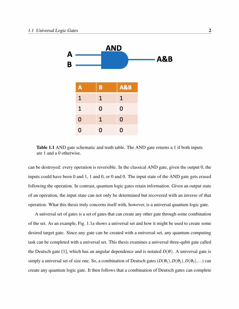
classical logic gate is the AND gate represented in Fig. 1. The AND gate takes in two bits and
returns a single bit in the state 1 if both input bits are in a state 1 and a 0 otherwise.
For quantum logic gates, information is stored in qubits rather than bits. Qubits are in a
superposition of the basis states |0〉 and |1〉. Additionally, in quantum logic gates, no information
1
1.1 Universal Logic Gates 2
Table 1.1 AND gate schematic and truth table. The AND gate returns a 1 if both inputsare 1 and a 0 otherwise.
can be destroyed: every operation is reversible. In the classical AND gate, given the output 0, the
inputs could have been 0 and 1, 1 and 0, or 0 and 0. The input state of the AND gate gets erased
following the operation. In contrast, quantum logic gates retain information. Given an output state
of an operation, the input state can not only be determined but recovered with an inverse of that
operation. What this thesis truly concerns itself with, however, is a universal quantum logic gate.
A universal set of gates is a set of gates that can create any other gate through some combination
of the set. As an example, Fig. 1.1a shows a universal set and how it might be used to create some
desired target gate. Since any gate can be created with a universal set, any quantum computing
task can be completed with a universal set. This thesis examines a universal three-qubit gate called
the Deutsch gate [1], which has an angular dependence and is notated D(θ). A universal gate is
simply a universal set of size one. So, a combination of Deutsch gates (D(θ1),D(θ2),D(θ3), ...) can
create any quantum logic gate. It then follows that a combination of Deutsch gates can complete
1.1 Universal Logic Gates 3
(a) An example of some target gate be-ing create with a universal set of gates.A universal set with gates 1, 2, and 3 cancreate any gate if combined correctly.
(b) An example of the same target gatebeing created with a universal Deutschgate. Deutsch gates combined togethercan yield any gate.
Figure 1.1 An example of how some target gate could be created with (a) a universal setof gates and (b) the universal Deutsch gate.
any quantum computational task. How the Deutsch gate might be used to create some desired target
gate is shown in Fig. 1.1b.
Typically, quantum computing is done with a universal set of logic gates. Despite the broad use
of universal sets, the use of a single universal gate rather than a set has several advantages. Using a
single universal gate bypasses the challenge of achieving a high fidelity on each gate in a set. The
fidelity of a gate is a measure of how accurate the gate is. Specifically, the fidelity of a gate is how
often, on average, the output of the gate is the desired output. Uncontrollable noise like decoherence
is inherent to all systems and limits how high a fidelity gates can attain. So, using the Deutsch
gate would only require making sure that the Deutsch gate had a high fidelity. On the other hand, a
universal set requires you to assess how high a fidelity several different gates have. Additionally,
known universal gates—like the Deutsch gate examined in this thesis—have an angular dependence
(described in more detail in Section 1.2) that allows for simple changes in the operation completed
1.1 Universal Logic Gates 4
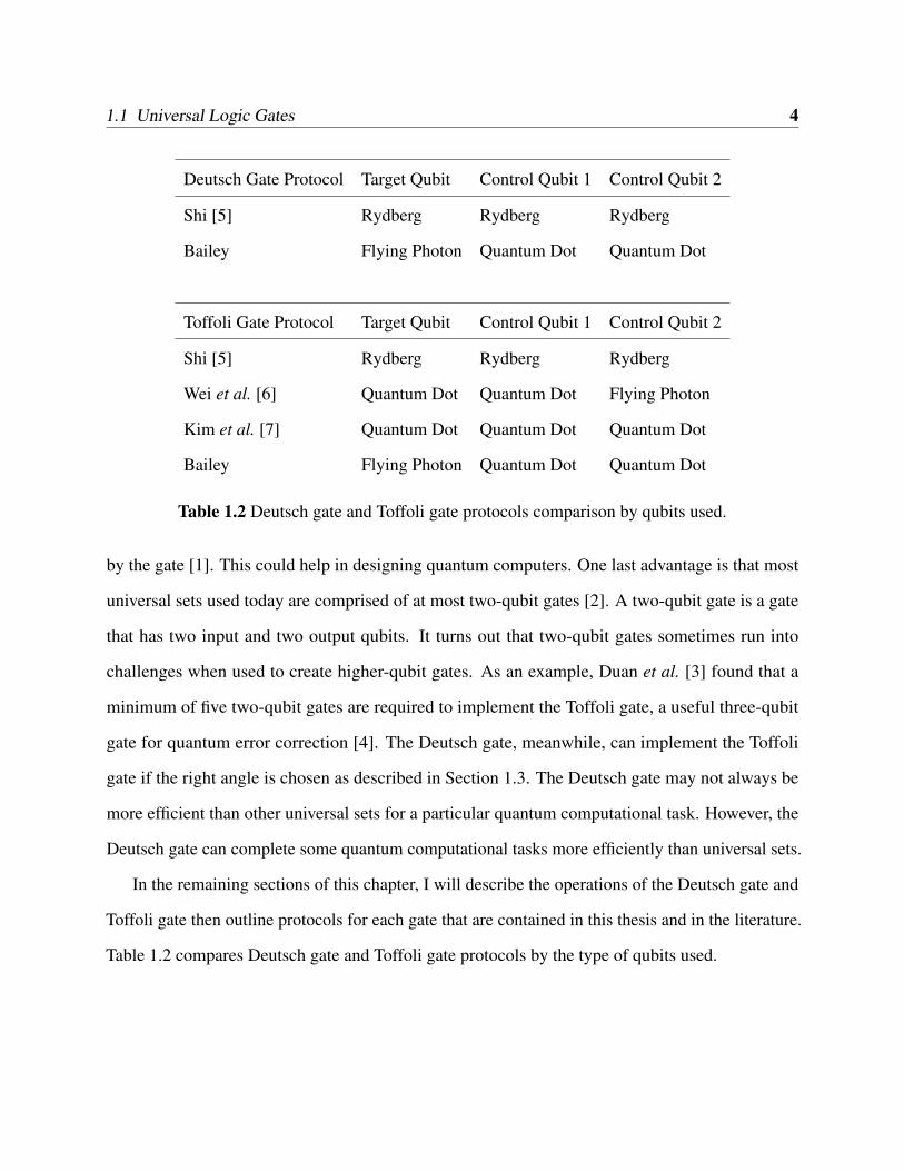
Deutsch Gate Protocol Target Qubit Control Qubit 1 Control Qubit 2
Shi [5] Rydberg Rydberg Rydberg
Bailey Flying Photon Quantum Dot Quantum Dot
Toffoli Gate Protocol Target Qubit Control Qubit 1 Control Qubit 2
Shi [5] Rydberg Rydberg Rydberg
Wei et al. [6] Quantum Dot Quantum Dot Flying Photon
Kim et al. [7] Quantum Dot Quantum Dot Quantum Dot
Bailey Flying Photon Quantum Dot Quantum Dot
Table 1.2 Deutsch gate and Toffoli gate protocols comparison by qubits used.
by the gate [1]. This could help in designing quantum computers. One last advantage is that most
universal sets used today are comprised of at most two-qubit gates [2]. A two-qubit gate is a gate
that has two input and two output qubits. It turns out that two-qubit gates sometimes run into
challenges when used to create higher-qubit gates. As an example, Duan et al. [3] found that a
minimum of five two-qubit gates are required to implement the Toffoli gate, a useful three-qubit
gate for quantum error correction [4]. The Deutsch gate, meanwhile, can implement the Toffoli
gate if the right angle is chosen as described in Section 1.3. The Deutsch gate may not always be
more efficient than other universal sets for a particular quantum computational task. However, the
Deutsch gate can complete some quantum computational tasks more efficiently than universal sets.
In the remaining sections of this chapter, I will describe the operations of the Deutsch gate and
Toffoli gate then outline protocols for each gate that are contained in this thesis and in the literature.
Table 1.2 compares Deutsch gate and Toffoli gate protocols by the type of qubits used.
1.2 Deutsch Gate 5
1.2 Deutsch Gate
The Deutsch gate is a three-qubit universal quantum logic gate first proposed by David Deutsch in
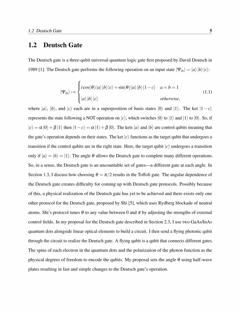
1989 [1]. The Deutsch gate performs the following operation on an input state |Ψin〉= |a〉 |b〉 |c〉:
|Ψin〉 7→
icos(θ) |a〉 |b〉 |c〉+ sin(θ) |a〉 |b〉 |1− c〉 a = b = 1
|a〉 |b〉 |c〉 otherwise,(1.1)
where |a〉, |b〉, and |c〉 each are in a superposition of basis states |0〉 and |1〉. The ket |1− c〉
represents the state following a NOT operation on |c〉, which switches |0〉 to |1〉 and |1〉 to |0〉. So, if
|c〉= α |0〉+β |1〉 then |1− c〉= α |1〉+β |0〉. The kets |a〉 and |b〉 are control qubits meaning that
the gate’s operation depends on their states. The ket |c〉 functions as the target qubit that undergoes a
transition if the control qubits are in the right state. Here, the target qubit |c〉 undergoes a transition
only if |a〉= |b〉= |1〉. The angle θ allows the Deutsch gate to complete many different operations.
So, in a sense, the Deutsch gate is an uncountable set of gates—a different gate at each angle. In
Section 1.3, I discuss how choosing θ = π/2 results in the Toffoli gate. The angular dependence of
the Deutsch gate creates difficulty for coming up with Deutsch gate protocols. Possibly because
of this, a physical realization of the Deutsch gate has yet to be achieved and there exists only one
other protocol for the Deutsch gate, proposed by Shi [5], which uses Rydberg blockade of neutral
atoms. Shi’s protocol tunes θ to any value between 0 and π by adjusting the strengths of external
control fields. In my proposal for the Deutsch gate described in Section 2.3, I use two GaAs/InAs
quantum dots alongside linear optical elements to build a circuit. I then send a flying photonic qubit
through the circuit to realize the Deutsch gate. A flying qubit is a qubit that connects different gates.
The spins of each electron in the quantum dots and the polarization of the photon function as the
physical degrees of freedom to encode the qubits. My proposal sets the angle θ using half-wave
plates resulting in fast and simple changes to the Deutsch gate’s operation.
1.3 Toffoli Gate 6
1.3 Toffoli Gate
The Toffoli gate is a universal gate for classical reversible computing [8], a subset of classical
computing. Thus, any reversible classical logic gate can be created with a combination of Toffoli
gates. Some classical computing operations like the AND operation are not reversible; they destroy
information. A reversible operator has an inverse operation associated with it. So, the inputs can be
used to find the outputs and vice versa. Any reversible operation can be enacted by a quantum logic
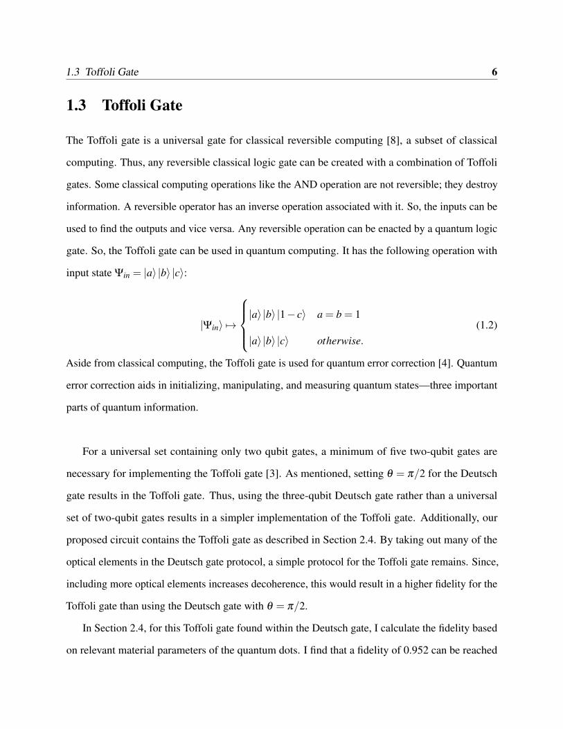
gate. So, the Toffoli gate can be used in quantum computing. It has the following operation with
input state Ψin = |a〉 |b〉 |c〉:
|Ψin〉 7→
|a〉 |b〉 |1− c〉 a = b = 1
|a〉 |b〉 |c〉 otherwise.(1.2)
Aside from classical computing, the Toffoli gate is used for quantum error correction [4]. Quantum
error correction aids in initializing, manipulating, and measuring quantum states—three important
parts of quantum information.
For a universal set containing only two qubit gates, a minimum of five two-qubit gates are
necessary for implementing the Toffoli gate [3]. As mentioned, setting θ = π/2 for the Deutsch
gate results in the Toffoli gate. Thus, using the three-qubit Deutsch gate rather than a universal
set of two-qubit gates results in a simpler implementation of the Toffoli gate. Additionally, our
proposed circuit contains the Toffoli gate as described in Section 2.4. By taking out many of the
optical elements in the Deutsch gate protocol, a simple protocol for the Toffoli gate remains. Since,
including more optical elements increases decoherence, this would result in a higher fidelity for the
Toffoli gate than using the Deutsch gate with θ = π/2.
In Section 2.4, for this Toffoli gate found within the Deutsch gate, I calculate the fidelity based
on relevant material parameters of the quantum dots. I find that a fidelity of 0.952 can be reached
1.4 Prior Work 7
using values for the material parameters that have been achieved in the lab. Kim et al. [7] proposed
to create a Toffoli gate with the same GaAs/InAs quantum dots presented here and reach a higher
fidelity for the same values of material parameters. However, they do not show that their protocol
can transition into a Deutsch gate protocol as the Toffoli gate I present can.
1.4 Prior Work
The Deutsch gate has never been experimentally realized. However, Shi [5] has proposed creating a
Deutsch gate using Rydberg Blockade of Neutral Atoms. While there is not much published work
on creating a Deutsch gate, the GaAs/InAs quantum dots used in my protocol have been used for
many quantum information applications following the work of Hu et al. [9, 10], who showed that
GaAs/InAs quantum dots could be used as entanglement beam splitters. Bonato et al. [11] proposed
using these quantum dots to create both a CNOT gate and a Bell state analyzer. Their proposal for a
CNOT gate uses a flying photonic qubit that interacts with one quantum dot. Whereas quantum dots
are stationary in the circuit, the photonic qubit travels through the circuit and can go on to connect
with other gates, hence the term flying. Wei et al. [6] created protocols for the CNOT, Toffoli, and
Fredkin gates. Their protocols use a flying photonic qubit as a control qubit rather than as a target
qubit like the protocols in this thesis and in [11]. Kim et al. [7] also proposed creating a CNOT
gate, Toffoli gate, and a Fredkin gate. Their CNOT gate differs from the CNOT gate proposed by
Bonato et al. in that the qubits used are only the spins of the electrons in two separate quantum dots.
Likewise, Kim et al. [7] Toffoli gate differs from my own in the same manner; only the spins of
electrons inside three separate quantum dots are used. Thus, the gates proposed by Kim et al. are
more geared toward storage. Whereas the gates proposed by Bonato et al. [11], by Wei et al. [6],
and by myself are more useful for communication networks since we include a flying photonic
qubit that can connect different gates together. Table 1.2 shows how the different Deutsch gate and
1.5 Proposal 8
Toffoli gate protocols referenced here compare based on the qubits used.
Additionally, using these GaAs/InAs quantum dots, Wang et al. [12] created a protocol for a
quantum repeater and Wang et al. [13] created protocols for a two-qubit phase gate and teleportation
of a CNOT gate. These schemes and others similar to them can be found in a review by Reiserer et
al. [14]. The majority of systems considered in [14] involve systems other than these GaAs/InAs
quantum dots. The review covers cavity-based quantum networks that involve flying photonic
qubits.
1.5 Proposal
I propose creating a Deutsch gate by combining two singly charged GaAs/InAs quantum dots with
linear optical elements as seen in Fig. 2.2 and described in Section 2.3. I expand upon schemes by
Bonato et al. [11] who proposed using GaAs/InAs quantum dots to create a CNOT gate. One qubit
will be an incoming photon’s polarization state while the other two qubits will be the state of the
electrons’ spins inside the quantum dots. In my Deutsch gate protocol, a variable angle θ can be
controlled by changing the angle of half-wave plates. This allows the Deutsch gate to quickly and
easily change its angle and perform different operations. The three qubits used in my Deutsch gate
protocol are the spins of the electrons confined to the quantum dots and the photon that interacts
with the quantum dots and passes through the optical elements. In my scheme, the two electron
spins take on the role of control qubits while the photonic qubit functions as the target qubit. Only
when both electrons are spin-up does the photonic qubit undergo a transition. The flying photonic
qubit also allows for quantum communication since it can go on to interact with other gates.
1.6 Overview 9
1.6 Overview
Before the Deutsch gate circuit can be understood, the individual components must be explained.
First, in Section 2.1, I describe the interaction between the quantum dots and an incoming photon.
In Section 2.2, I describe the operation of different optical elements employed in my Deutsch gate
protocol. With the description of the quantum dot transitions and optical elements, the Deutsch
gate circuit can be understood. In Section 2.3, I walk through the Deutsch gate construction step by
step. I discuss how the input states transition into intermediate states and then to a final output state.
Following the description of the Deutsch gate, in Section 2.4, I show how a Toffoli gate can be
created by removing optical elements from our protocol. I calculate the fidelity of this Toffoli gate
in terms of operating parameters of the quantum dots. In Section 2.5, I show how appropriate Toffoli
gates can be turned into Deutsch gates using a sub-circuit of my Deutsch gate design. Finally, in
Chapter 3, I discuss my results, future work, and compare my Deutsch gate proposal with Shi’s [5]
proposal, the only other existing Deutsch gate proposal.
Chapter 2
Deutsch Gate Proposal
2.1 Quantum Dot Transitions
My Deutsch gate protocol makes use of GaAs/InAs quantum dots and various linear optical elements.
Before outlining the protocol, I will describe the effect of each component separately—starting with
the quantum dots.
Circularly polarized photons undergo transitions after interacting with the electron in a singly
charged GaAs/InAs quantum dot as described by Bonato et al. [11]. I will only present these
transitions in the amount of detail needed for my purpose, which is to describe the state of a photon
before and after interacting with a GaAs/InAs quantum dot. A more detailed description of these
transitions can be found in [11].
I assume an arbitrary state for the electron in the GaAs/InAs quantum dot, |e〉= k1 |+〉+ k2 |−〉,
where |+〉 represents the electron spin-up state with respect to the axis of the incoming photon,
|−〉 represents the spin-down state with respect to that same axis as seen in Fig. 2.1, and k1 and
k2 are normalized coefficients. The incoming photon is in some superposition of right circularly
polarized light |R〉 and left circularly polarized light |L〉. The incoming photon will either reflect
10
2.2 Optical Elements 11
(a) Photon traveling in −z direction. (b) Photon traveling in +z direction.
Figure 2.1 Photon transition rules after interacting with the GaAs/InAs quantum dot. Thearrow superscripts indicate the direction of travel for the photon.
off the quantum dot and invert its polarization, go from |R〉 to |L〉 or vice versa, or will transmit
through the quantum dot picking up a phase shift of π while keeping its polarization state. In either
case, the state of the electron remains unchanged. The transformation of the photon’s polarization
state differs depending on whether the photon is incident from above (traveling in the −z direction)
or below (traveling in the +z direction) as can be seen in Fig. 2.1a and b.
plates , mirrors, π phase shiftters, linear polarizing beam splitters, and circularly polarizing beam
splitters. Jones matrices describe the effect of each element—aside from the beam splitters—on the
polarization of light. The Jones matrices of each element are listed in Table 2.1. These matrices act
on two-dimensional Jones vectors representing the polarization of light. For example, right and left
circularly polarized light are represented by the following Jones vectors:
|R〉=
1/√
2
i/√
2
(2.1)
and
2.2 Optical Elements 12
|L〉=
1/√
2
−i/√
2
. (2.2)
The top entry in the Jones vector represents the horizontal component of the polarization while the
bottom entry represents the vertical component. For a more complete treatment of Jones calculus,
see Peatross and Ware [15].
Element Jones Matrix
Half-Wave Plate
cos2φ sin2φ
sin2φ −cos2φ
Quarter-Wave Plate
cosφ 2 + isinφ 2 sinφ cosφ − isinφ cosφ
sinφ cosφ − isinφ cosφ sinφ 2 + icosφ 2
Mirror
1 0
0 −1
π Phase Shiftter
−1 0
0 −1
Table 2.1 Jones matrices for optical elements.
The linear polarizing beam splitters send the horizontal component of light in one direction
and vertical light in the other. Similarly, circular polarizing beam splitters send right circularly
polarized light one way and left circularly polarized light another. In this work and the diagram of
2.3 Deutsch Gate Circuit 13
the Deutsch gate seen in Fig. 2.2, horizontally polarized light passes through linear polarizing beam
splitters, while vertically polarized light is reflected. For circularly polarized beam splitters, the
right circularly polarized light transmits, while the left circularly polarized light reflects.
2.3 Deutsch Gate Circuit
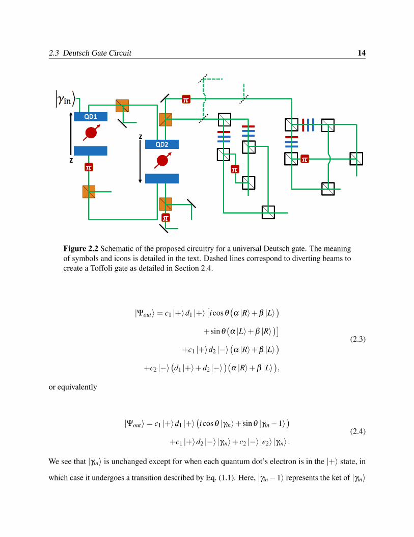
The Deutsch gate protocol is displayed in Fig. 2.2. The two GaAs/InAs quantum dots are labeled
QD1 and QD2. The green lines represent the paths the incident photon may take. Mirrors are
represented by diagonal black lines. The red squares indicate paths phase shifted by π . Red
lines represent half-wave plates, while blue lines represent quarter-wave plates. The orange beam
splitters are circularly polarizing, while the white beam splitters are linearly polarizing. Notice that
each quantum dot has a different reference axis indicated by an arrow labeled z, which affects the
transitions that happen between it and an incoming photon. The black dashed lines are removable
mirrors that divert beams represented by green dashed lines to implement the Toffoli gate as
described in Section 2.4.
The protocol starts with an incident photon in the polarization state |γin〉= α |R〉+β |L〉, where
|R〉 represents a right circularly polarized state, |L〉 represents a left circularly polarized state, and
α and β are normalized constants. The electrons in the quantum dots start out in the spinor states
|e1〉= c1 |+〉+ c2 |−〉 and |e2〉= d1 |+〉+d2 |−〉, where |+〉 and |−〉 represent the electron in each
quantum dot being in the spin-up or spin-down state respectively with respect to the z axes labeled
in Fig. 2.2 and c1, c2, d1, and d2 are all normalized constants. Note again that each electron state
is defined according to different axes as indicated in Fig. 2.2. To achieve the Deutsch gate we
want to transform our three-qubit input state |Ψin〉 = |γin〉 |e1〉 |e2〉, according to Eq. (1.1) with
|a〉= |e1〉 , |b〉= |e2〉, and |c〉= |γin〉, into a new three-qubit state
2.3 Deutsch Gate Circuit 14
Figure 2.2 Schematic of the proposed circuitry for a universal Deutsch gate. The meaningof symbols and icons is detailed in the text. Dashed lines correspond to diverting beams tocreate a Toffoli gate as detailed in Section 2.4.
|Ψout〉= c1 |+〉d1 |+〉[icosθ
(α |R〉+β |L〉
)+sinθ
(α |L〉+β |R〉
)]+c1 |+〉d2 |−〉
(α |R〉+β |L〉
)+c2 |−〉
(d1 |+〉+d2 |−〉
)(α |R〉+β |L〉
),
(2.3)
or equivalently
|Ψout〉= c1 |+〉d1 |+〉(icosθ |γin〉+ sinθ |γin−1〉
)+c1 |+〉d2 |−〉|γin〉+ c2 |−〉|e2〉 |γin〉 .
(2.4)
We see that |γin〉 is unchanged except for when each quantum dot’s electron is in the |+〉 state, in
which case it undergoes a transition described by Eq. (1.1). Here, |γin−1〉 represents the ket of |γin〉
2.3 Deutsch Gate Circuit 15
having undergone a NOT operation where the polarization is inverted. Thus, |γin−1〉=α |L〉+β |R〉.
Note, also, that each electron stays in its initial spinor state as can be seen from the GaAs/InAs
quantum dot transition rules in Fig. 2.1.
Now I will describe the transitions which occur as the photon goes through the circuit. I will
follow how the input state |Ψin〉 transitions with each step until it becomes |Ψout〉. First, |Ψin〉 will
interact with QD1 transforming into |ΨQD1〉. Then |ΨQD1〉 will interact with some optical elements
transforming into |Ψ2〉. The photon then interacts with QD2 resulting in |ΨQD2〉. Then the photon
will interact with the optical elements prior to the wave plates resulting in |Ψ4〉. Finally, |Ψ4〉 will
traverse the series of wave plates and the rest of the circuit to transition into the output state |Ψout〉.
The incident photon first interacts with the first quantum dot labeled QD1, which transforms the
input state |Ψin〉= |γin〉 |e1〉 |e2〉 into
|ΨQD1〉=[c1 |+〉
(−α |R〉+β |R〉
)+ c2 |−〉
(α |L〉−β |L〉
)]⊗|e2〉 . (2.5)
Following the schematic in Fig. 2, the bottom output beams from QD1 goes through a phase shift
of π and is split by a circularly polarized beam splitter while the top output beam is split by another
circularly polarized beam splitter and the left circularly polarized half is flipped to right circularly
polarized light by a mirror. This transforms |ΨQD1〉 into
|Ψ2〉=[c1 |+〉
(α |R〉+β |R〉
)+ c2 |−〉
(α |R〉+β |L〉
)]⊗∣∣e−2 ⟩ . (2.6)
Next, the right circularly polarized terms associated with the first quantum dot being spin up interact
with QD2 while the spin-down terms are left untouched yielding
2.3 Deutsch Gate Circuit 16
|ΨQD2〉= c1 |+〉 [d1 |+〉(−α |R〉+β |L〉)
+d2 |−〉(α |L〉−β |R〉)]
+c2 |−〉(d1 |+〉+d2 |−〉)(α |R〉+β |L〉).
(2.7)
Both output beams following QD2 are then split according to their circular components and each
right circularly polarized component is phase shifted by π . Then all beams other than the left
circularly polarized component associated with QD1 and QD2 both being spin up have their
polarization flipped by mirrors resulting in
|Ψ4〉= c1 |+〉 [d1 |+〉(α |L〉+β |L〉)
+d2 |−〉(α |R〉+β |L〉)]
+c2 |−〉(d1 |+〉+d2 |−〉)(α |R〉+β |L〉).
(2.8)
Half-wave plates introduce the angular dependence of the Deutsch gate—represented by red
lines in Fig. 2.2, each at an angle φ = θ/2. Quarter-wave plates are represented by blue lines and
always occur in pairs. In each series of wave plates that the beams pass through in Fig. 2.2, the
first quarter-wave plate is set at an angle θ1 = π and the second quarter-wave plate is at an angle
θ2 = π/2. We will be taking the left circularly polarized components of the c1 |+〉d1 |+〉 term, α |L〉
and β |L〉, and transform them to take on the form of |Ψout〉. We do this by splitting each beam into
its linear components and pass all beams through the series of wave plates, which transforms α |L〉
Each grouping of terms corresponds to a different beam path, which are each split again into their
linear polarization components. The αisin(θ) |V 〉 term in Eq. (2.9) and the β i2 cos(θ) |V 〉 term in
Eq. (2.10) are each then phase shifted by π . Beams with identical α/β and cosine/sine terms are
then recombined using linear polarizing beam splitters to again produce circularly polarized light.
This all results in the original α |L〉 and β |L〉 terms transforming into
α |L〉 7→ α(icosθ |R〉+ sinθ |L〉)
β |L〉 7→ β (icosθ |L〉+ sinθ |R〉).(2.11)
This results in the desired final output state of
|Ψout〉= c1 |+〉d1 |+〉(icosθ [α |R〉+β |L〉]
+sinθ [α |L〉+β |R〉])
+c1 |+〉d2 |−〉(α |R〉+β |L〉)
+c2 |−〉(d1 |+〉+d2 |−〉)(α |R〉+β |L〉),
(2.12)
where each of the eight circularly polarized terms correspond to a separate output beam in Fig.( 2.2).
2.4 Toffoli Gate Circuit
The Toffoli gate is a three-qubit gate useful for quantum error correction [4]. As previously
mentioned, taking θ = π/2 in the Deutsch gate yields the Toffoli gate. However, my protocol can
achieve the Toffoli gate by other means. My Deutsch gate protocol can implement the Toffoli gate
2.4 Toffoli Gate Circuit 18
by diverting the beams before they reach the wave plates and linear beam splitters as shown in
Fig. 2.2.
Each additional element added to a protocol introduces decoherence, which lowers the fidelity
of a gate. Since this Toffoli gate protocol has fewer elements than using the Deutsch gate to create
a Toffoli gate, it should have a higher fidelity. The fidelity of a quantum logic gate refers to how
close, on average, the output state matches the intended output state. For example, if a gate has a
fidelity of 0.95 then it has a 95% chance of achieving the desired output state. The Toffoli gate’s
fidelity for different operating parameters of the quantum dots is found in Fig. 2.3. This plots the
fidelity in terms of the normalized coupling strength g/κ and normalized side leakage κs/κ , which
I calculated following the methods of Hu et al. [10]. This involves taking into account that the
transition rules described in Section 2.1 are not entirely accurate in a real-world setting. There is a
small chance of getting the opposite and unwanted transition. All elements in the circuit aside from
the quantum dots are assumed to be ideal in my calculations, however. From Fig. 2.3, we see that
we can reach a fidelity of 0.928 or higher when operating the GaAs/InAs quantum dots with a high
coupling strength and low side leakage. Experimentally, researchers have been able to operate these
quantum dots with a normalized coupling strength of g/κ = 2.4 and a normalized side leakage of
κs/κ = 0.01 as quoted in [7] . With these value the Toffoli gate would reach a fidelity of 0.952
based on my calculations.
Another Toffoli gate proposal by Kim et al. [7] also uses GaAs/InAs quantum dots. However, in
that proposal, three quantum dots are used as the qubits and no flying qubit is used. The Toffoli
gate proposed by Kim et al. can reach a fidelity of 0.966 with g/κ = 2.4 and κs/κ = 0.01, a value
0.014 higher than the Toffoli gate presented here at those operating parameters. My proposal has
additional uses, however. The protocol by Kim et al. does not use a photonic qubit and there is
no indication that they can implement the Deutsch gate using their Toffoli gate. Their proposal is
better geared toward storage, whereas the photonic qubit in my proposal allows for easier quantum
2.5 Deutsch Gate Design Generalization 19
Figure 2.3 The calculated fidelity of the Toffoli gate in terms of the normalized couplingstrength g/κ and normalized side leakage κs/κ .
communication. Other Toffoli gate protocols and their fidelities can be found for comparison in [7].
The considerably more involved fidelity calculattion for the Deutsch gate is not included in this
work.
2.5 Deutsch Gate Design Generalization
I introduced the Toffoli gate circuit in Section 2.4 as the Deutsch gate circuit with some elements
taken away as shown in Fig. 2.2. However, there are many ways to construct a Toffoli gate. In this
section, I suggest how appropriate Toffoli gates can have the latter half of my Deutsch gate protocol
added to yield a Deutsch gate. Any Toffoli gate protocol with a flying photonic target qubit whose
different |R〉 and |L〉 terms can be separated could have the proper outputs run through the latter
2.5 Deutsch Gate Design Generalization 20
Figure 2.4 Schematic of the Deutsch gate implemented by adding optical elements to anappropriate Toffoli gate. By taking the proper beams from a Toffoli gate with a flyingphotonic target qubit—namely those asociated with a = b = 1—and running them throughthe latter half of my Deutsch gate protocol, the Deutsch gate can be implemented.
part of the Deutsch gate circuit and thus create a Deutsch gate. I show in Fig. 2.4 how to implement
a Deutsch gate using an appropriate Toffoli gate.
More precisely, assume that the input of a Toffoli gate is |Ψin〉= |a〉 |b〉 |c〉 where |a〉= k1 |0〉+
k2 |1〉, |b〉 = d1 |0〉+ d2 |1〉, and |c〉 is a photonic target qubit with |c〉 = α |R〉+β |L〉. Then the