A LICENSE IS HEREBY GRANTED TO REPRODUCE THIS SPECIFICATION FOR INTERNAL USE ONLY. NO OTHER LICENSE, EXPRESS OR IMPLIED, BY ESTOPPEL OR OTHERWISE, IS GRANTED OR INTENDED HEREBY.
USB-IF AND THE AUTHORS OF THIS SPECIFICATION EXPRESSLY DISCLAIM ALL LIABILITY FOR INFRINGEMENT OF INTELLECTUAL PROPERTY RIGHTS, RELATING TO IMPLEMENTATION OF INFORMATION IN THIS SPECIFICATION. USB-IF AND THE AUTHORS OF THIS SPECIFICATION ALSO DO NOT WARRANT OR REPRESENT THAT SUCH IMPLEMENTATION(S) WILL NOT INFRINGE THE INTELLECTUAL PROPERTY RIGHTS OF OTHERS.
THIS SPECIFICATION IS PROVIDED "AS IS” AND WITH NO WARRANTIES, EXPRESS OR IMPLIED, STATUTORY OR OTHERWISE. ALL WARRANTIES ARE EXPRESSLY DISCLAIMED. NO WARRANTY OF MERCHANTABILITY, NO WARRANTY OF NON-INFRINGEMENT, NO WARRANTY OF FITNESS FOR ANY PARTICULAR PURPOSE, AND NO WARRANTY ARISING OUT OF ANY PROPOSAL, SPECIFICATION, OR SAMPLE.
IN NO EVENT WILL USB-IF OR USB-IF MEMBERS BE LIABLE TO ANOTHER FOR THE COST OF PROCURING SUBSTITUTE GOODS OR SERVICES, LOST PROFITS, LOSS OF USE, LOSS OF DATA OR ANY INCIDENTAL, CONSEQUENTIAL, INDIRECT, OR SPECIAL DAMAGES, WHETHE R UNDER CONTRACT, TORT, WARRANTY, OR OTHERWISE, ARISING IN ANY WAY OUT OF THE USE OF THIS SPECIFICATION, WHETHER OR NOT SUCH PARTY HAD ADVANCE NOTICE OF THE POSSIBILITY OF SUCH DAMAGES.
All product names are trademarks, registered trademarks, or service ma rks of their respective owners.
Please send comments via electronic mail to techadmin@usb,org
USB-IF Device Working Group - 3 - USB Type-C Locking Connector Revision 1.0
Revision History ..........................................................................................................................................................5
1.3 Related Documents.................................................................................................................................6
This specification defines the mechanical requirements for USB Type-C plug connectors and the guidelines for the Type-C receptacle mounting configuration to provide a standardized screw lock mechanism for USB Type-C connectors and cables.
The USB Type-C Cable and Connector Specification defines a new receptacle, plug, cable and detection mechanisms that are compatible with existing USB interface electrical and functional specifications. This specification in conjunction with the USB Type-C Cable and Connector Specification define the following to provide standardized screw locking mechanisms for the USB Type-C plug:
USB Type-C plug connector with a single locking screw
USB Type-C plug connector with dual locking screws
Guidelines for configuration of mounting screw hole(s) relative to the USB Type-C receptacle
1.2 Scope
This specification is intended as a supplement to the existing USB 2.0, USB 3.1 and USB Type-C specifications. It addresses only the elements required to implement and support the USB Type-C receptacles, plugs, and cables with locking hardware.
Normative information is provided to allow interoperability of components designed to this specification. Informative information, when provided, may il lustrate possible design implementations. Related Documents
1.3 Related Documents
USB 2.0 Universal Serial Bus Revision 2.0 Specification This includes the entire document release package. http://www.usb.org/developers/docs/usb20_docs
USB 3.1 Universal Serial Bus Revision 3.1 Specification This includes the entire document release package. http://www.usb.org/developers/docs
USB Type-C Universal Serial Bus Type-C Cable and Connector Specification This includes the entire document release package. http://www.usb.org/developers/usbtypec
1.4 Conventions
1.4.1 Precedence
If there is a conflict between text, figures, and tables, the precedence shall be tables, figures, and then text.
1.4.2 Keywords
1.4.2.1 Informative
Informative is a keyword that describes information with this specification that intends to discuss and clarify requirements and features as opposed to mandating them.
1.4.2.2 May
May is a keyword that indicates a choice with no implied preference.
N/A is a keyword that indicates that a field or value is not applicable and has no defined value and shall not be checked or used by the recipient.
1.4.2.4 Normative
Normative is a keyword that describes features that are mandated by this specification.
1.4.2.5 Optional
Optional is a keyword that describes features not mandated by this specification. However, if an optional feature is implemented, the feature shall be impl emented as defined by this specification (optional normative).
1.4.2.6 Reserved
Reserved is a keyword indicating reserved bits, bytes, words, fields, and code values that are set-aside for future standardization. Their use and interpretation may be specified by future extensions to this specification and, unless otherwise stated, shall not be utilized or adapted by vendor implementation. A reserved bit, byte, word, or field shall be set to zero by the sender and shall be ignored by the receiver. Reserved field values shall not be sent by the sender and, if received, shall be ignored by the receiver.
1.4.2.7 Shall
Shall is a keyword indicating a mandatory (normative) requirement. Designers are mandated to implement all such requirements to ensure interoperability with oth er compliant Devices.
1.4.2.8 Should
Should is a keyword indicating flexibility of choice with a preferred alternative. Equivalent to the phrase “it is recommended that”.
1.5 Terms and Abbreviations
Term Description
overmold Overmold is the term used in this specification to describe the body of the plug connector behind the mating interface shell. The term does not imply a particular manufacturing process, material, or feature hardness.
USB-IF Device Working Group - 8 - USB Type-C Locking Connector Revision 1.0
This section is an overview of the contents of this document and provides a brief summary of each of the subsequent sections.
Section 1 defines the purpose of this specification and includes the scope, a list of related specifications, and definitions for terms and abbreviations that have a specific meaning in the context of this specification.
Section 2 provides a summary of each section.
Section 3 provides normative information regarding the physical attributes of the USB Type -C plug locking connectors.
Annex A provides an informative guide for mounting of the USB Type-C receptacle relative to the locking screw mounting holes.
3 USB Type-C Locking Connector Plugs
This section supplements the USB Type-C Cable and Connector Specification by defining the dimensions for screw lock variations of the Type-C plug connector. There are two variants of the locking connector defined:
USB Type-C plug with single locking screw
USB Type-C plug with dual locking screws
The basic USB Type-C plug connector is defined by the USB Type-C Cable and Connector Specification. The dimensions defined by this specification are used in conjunction with the USB Type-C base specification to provide two standardized locking connector design options and to provide a means for USB-IF to certify the USB Type-C plug connectors with locking screws.
The locking screws of the USB Type-C locking plugs are fully retractable so that that the plug may be plugged into an application using a USB Type-C receptacle that does not support the locking screw function.
3.1 Single Screw USB Type-C Locking Plug
The single screw USB Type-C plug connector is defined for applications that may have restricted width for the locking screws. If the application provides only one threaded hole with respect the receptacle location, then the USB Type-C plug connector is electrically functional in either mated orientation but the locking mechanism is functional in only one mated orientation. If the application provides threaded holes both above and below the receptacle, then the single screw version may be locked in either mating orientation.
The single screw USB Type-C locking plug shall comply with the dimensions defined in the USB Type-C Cable and Connector Specification with the exceptions defined in Figure 3-1 for the overmold and locking screw. The following requirements also apply to the implementation:
A. The locking screw shall extend to the dimension defined in Figure 3-1 and retract to be flush or below the overmold surface to support mating to non -locking implementations.
B. The location and float of the locking screw shall allow the locking screw to mount to a threaded hole located in the position defined in Figure 3-2.
USB-IF Device Working Group - 9 - USB Type-C Locking Connector Revision 1.0
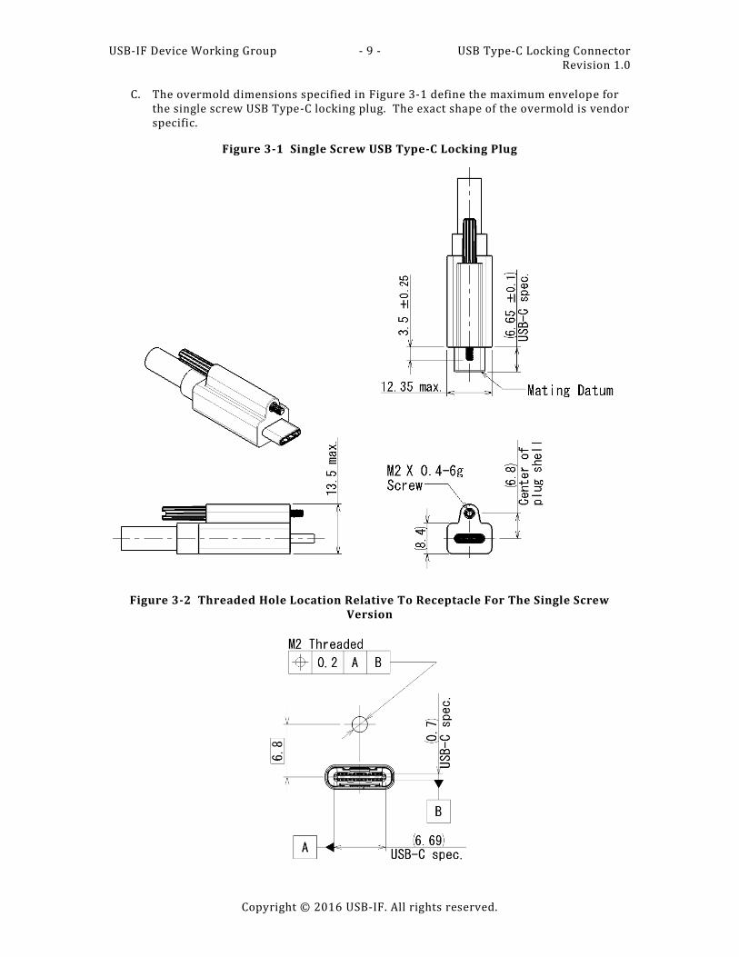
C. The overmold dimensions specified in Figure 3-1 define the maximum envelope for the single screw USB Type-C locking plug. The exact shape of the overmold is vendor specific.
Figure 3-1 Single Screw USB Type-C Locking Plug
Figure 3-2 Threaded Hole Location Relative To Receptacle For The Single Screw Version
USB-IF Device Working Group - 10 - USB Type-C Locking Connector Revision 1.0
The dual screw USB Type-C plug connector is defined for applications that may have restricted height or that may require the additional securing capability provided by a second locking screw. The dual screw version may be locked in ei ther mating orientation.
The dual screw USB Type-C locking plug shall comply with the dimensions defined in the USB Type-C Cable and Connector Specification with the exceptions defined in Figure 3-3 for the overmold and locking screws. The following requirements also apply to the implementation:
A. The locking screws shall extend to the dimension defined in Figure 3-3 and retract to be flush or below the overmold surface to support mating to non -locking implementations.
B. The location and float of the locking screws shall allow the locking screws to mount to threaded holes located in the positions defined in Figure 3-4.
C. The overmold dimensions specified in Figure 3-3 define the maximum envelope for the dual screw USB Type-C locking plug. The exact shape of the overmold is vendor specific.
Figure 3-3 Dual Screw USB Type-C Locking Plug
USB-IF Device Working Group - 11 - USB Type-C Locking Connector Revision 1.0
Annex A Type-C Locking Connector Receptacle Positioning (Informative)
For Type-C connectors without the locking features, the minimum plug shell length is 6.55 mm. Since the locking version is required to have the same plug shell length, the system implementation should be designed such that the distance from the receptacle mating datum to the surface that the plug overmold seats against is a maximum of 6.5 mm to allow the shortest allowed plug shell to seat against the mating datum of the receptacle . Figure A-5 illustrates this recommendation. The single screw version of the USB Type -C locking plug is used in the figure for illustration clarity only and does not imply any preference of one version over the other. The dimensions shown in the figure apply to either USB Type-C locking plug version.
The implementation of the system should provide for full mating of the USB Type -C plug and receptacle pair while keeping in consideration the stresses created as the locking mechanism closes the gap and forces the plug beyond the fully mated condition with the receptacle. Figure A-6 shows an implementation where the surface that the plug overmold seats against is at 6.2 mm from the receptacle mating datum. This resul ts in a gap of 0.45 ± 0.1 mm while at the maximum dimension of 6.5 mm shown in Figure A-5 results in a gap of 0.15 ± 0.1 mm. Various methods may be implemented to limit the stresses caused by the overmated condition resulting from tightening the locking screws beyond the point where the plug shell contacts the receptacle mating datum. The locking screw mechanism is similar to that used by other connector types, therefore, solutions used for those applications may provide adequate protection for the Type-C implementation.
(6.65+/-0.1) (USB C spec)
Mating datum
6.5 max
USB-IF Device Working Group - 13 - USB Type-C Locking Connector Revision 1.0


![USB Type-C Connector System Software Interface Specification · Document Number: 336205-002 . USB Type-C™ Connector System Software Interface [UCSI] Requirements Specification .](https://static.documents.pub/doc/80x56/5f68ce2b497d8b507b46b775/usb-type-c-connector-system-software-interface-specification-document-number-336205-002.jpg)


