80
Product Brochure Universal Wireless Test Set MT8870A/MT8872A Excellent Eco Product

Product Brochure
Universal Wireless Test SetMT8870A/MT8872A
Excellent Eco Product

Two Anritsu Solutions for High-Density Production Lines
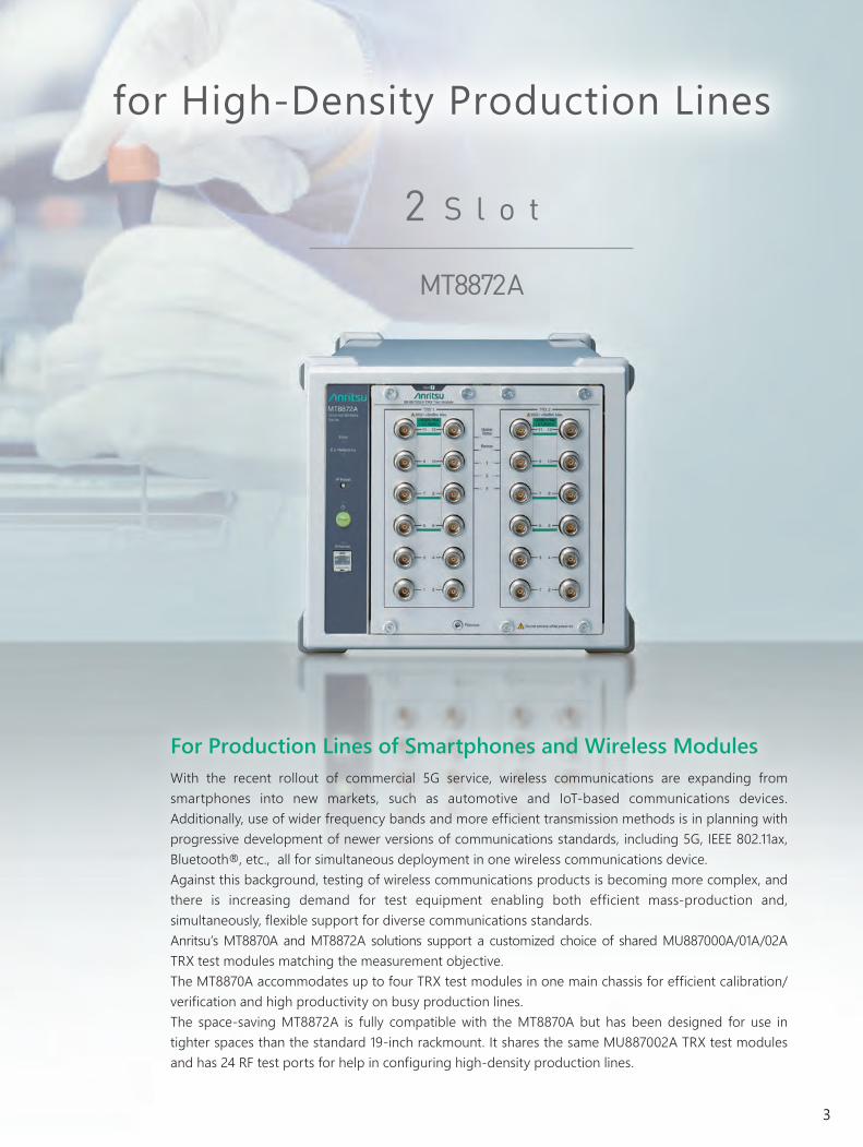
For Production Lines of Smartphones and Wireless ModulesWith the recent rollout of commercial 5G service, wireless communications are expanding from smartphones into new markets, such as automotive and IoT-based communications devices. Additionally, use of wider frequency bands and more efficient transmission methods is in planning with progressive development of newer versions of communications standards, including 5G, IEEE 802.11ax, Bluetooth®, etc., all for simultaneous deployment in one wireless communications device. Against this background, testing of wireless communications products is becoming more complex, and there is increasing demand for test equipment enabling both efficient mass-production and, simultaneously, flexible support for diverse communications standards. Anritsu’s MT8870A and MT8872A solutions support a customized choice of shared MU887000A/01A/02A TRX test modules matching the measurement objective.The MT8870A accommodates up to four TRX test modules in one main chassis for efficient calibration/verification and high productivity on busy production lines.The space-saving MT8872A is fully compatible with the MT8870A but has been designed for use in tighter spaces than the standard 19-inch rackmount. It shares the same MU887002A TRX test modules and has 24 RF test ports for help in configuring high-density production lines.
MT8870A
4 S l o t
MT8872A
2 S l o t
2
Two Anritsu Solutions for High-Density Production Lines
For Production Lines of Smartphones and Wireless ModulesWith the recent rollout of commercial 5G service, wireless communications are expanding from smartphones into new markets, such as automotive and IoT-based communications devices. Additionally, use of wider frequency bands and more efficient transmission methods is in planning with progressive development of newer versions of communications standards, including 5G, IEEE 802.11ax, Bluetooth®, etc., all for simultaneous deployment in one wireless communications device. Against this background, testing of wireless communications products is becoming more complex, and there is increasing demand for test equipment enabling both efficient mass-production and, simultaneously, flexible support for diverse communications standards. Anritsu’s MT8870A and MT8872A solutions support a customized choice of shared MU887000A/01A/02A TRX test modules matching the measurement objective.The MT8870A accommodates up to four TRX test modules in one main chassis for efficient calibration/verification and high productivity on busy production lines.The space-saving MT8872A is fully compatible with the MT8870A but has been designed for use in tighter spaces than the standard 19-inch rackmount. It shares the same MU887002A TRX test modules and has 24 RF test ports for help in configuring high-density production lines.
MT8870A
4 S l o t
MT8872A
2 S l o t
3

Mobile terminal manufacturers require not only production line efficiency but
also the flexibility to adapt to changes in wireless standards. The MT8870A is the
ideal instrument to meet these needs.
Built-in Signal Generator and Signal Analyzer in Each Test Module
Wide Bandwidth
Wide Frequency Range up to 6 GHz
Each Test Module Supports Multiple Wireless Standards
MX8870xxA SeriesTX MeasurementSoftware License
TRX Test ModuleMU88700xA
Each standard is supported easily using a cost-effective licensing scheme
Licenses are obtained by adding TX measurement software packages and waveform files.
Future-proof Production Lines
MV887xxxA SeriesWaveforms
License
TRX Test ModuleMU887000A
TRX Test ModuleMU887000Awith MU887000A-002 (Audio)
TRX Test ModuleMU887001A
TRX Test ModuleMU887002Awith MU887007A-007(7 GHz Extension Function)
TRX Test ModuleMU887001Awith MU887001A-002 (Audio)
The TRX Test Module MU887000A/01A/02A (MU88700xA) has been developed for communication terminal device production lines. Each installed test module has an independent high-performance signal generator and signal analyzer.
To support the NR Sub-6 GHz and WLAN 802.11ax wireless communicationsstandards requiring bandwidths of more than 100 MHz, the analysisbandwidth of the signal analyzer (SA) and modulation bandwidth of the signal generator (SG) in the MU887000A/01A is 160 MHz as standard, while that in the MU887002A is 200 MHz.
The signal generator and signal analyzer in the MU887000A/01A have an upper frequency limit of 3.8 GHz as standard, but this can be extended to 6 GHz as an option.The signal generator and signal analyzer in the MU887002A have an upper frequency limit of 6 GHz as standard and it can be extended to 7.3 GHz as an option.They flexibly support new wireless communication standards that cannot be supported by dedicated instruments for specific frequencies.
One MU88700xA supports multiple wireless communication standards.
High Performance Coupled with F lexibi l i ty and Expandabi l i ty
TRX Test ModuleMU887002A
MU887000A/01A
MU887002A
MU887002A + MU887002A-007
MU887000A/01A + MU887000A/01A-001
Wide Frequency Range
7.3
4

Mobile terminal manufacturers require not only production line efficiency but
also the flexibility to adapt to changes in wireless standards. The MT8870A is the
ideal instrument to meet these needs.
Built-in Signal Generator and Signal Analyzer in Each Test Module
Wide Bandwidth
Wide Frequency Range up to 6 GHz
Each Test Module Supports Multiple Wireless Standards
MX8870xxA SeriesTX MeasurementSoftware License
TRX Test ModuleMU88700xA
Each standard is supported easily using a cost-effective licensing scheme
Licenses are obtained by adding TX measurement software packages and waveform files.
Future-proof Production Lines
MV887xxxA SeriesWaveforms
License
TRX Test ModuleMU887000A
TRX Test ModuleMU887000Awith MU887000A-002 (Audio)
TRX Test ModuleMU887001A
TRX Test ModuleMU887002Awith MU887007A-007(7 GHz Extension Function)
TRX Test ModuleMU887001Awith MU887001A-002 (Audio)
The TRX Test Module MU887000A/01A/02A (MU88700xA) has been developed for communication terminal device production lines. Each installed test module has an independent high-performance signal generator and signal analyzer.
To support the NR Sub-6 GHz and WLAN 802.11ax wireless communicationsstandards requiring bandwidths of more than 100 MHz, the analysisbandwidth of the signal analyzer (SA) and modulation bandwidth of the signal generator (SG) in the MU887000A/01A is 160 MHz as standard, while that in the MU887002A is 200 MHz.
The signal generator and signal analyzer in the MU887000A/01A have an upper frequency limit of 3.8 GHz as standard, but this can be extended to 6 GHz as an option.The signal generator and signal analyzer in the MU887002A have an upper frequency limit of 6 GHz as standard and it can be extended to 7.3 GHz as an option.They flexibly support new wireless communication standards that cannot be supported by dedicated instruments for specific frequencies.
One MU88700xA supports multiple wireless communication standards.
High Performance Coupled with F lexibi l i ty and Expandabi l i ty
TRX Test ModuleMU887002A
MU887000A/01A
MU887002A
MU887002A + MU887002A-007
MU887000A/01A + MU887000A/01A-001
Wide Frequency Range
7.3
5
The Bluetooth® word mark and logos are registered trademarks owned by Bluetooth SIG, Inc. and any use of such marks by Anritsu is under license.
TD-SCDMA
LTE-Advanced LTE
HSPA
DVB-H
NB-IoT Cat-M
802.11a
V2X 802.11p
802.11g
802.11b
802.11n
802.11ac(Wave2)
802.11ax
LTE-V2X
Z-Wave
FM
Bluetooth5
802.15.4
BeiDouQZSSGalileo
GLONASS
GPS
ISDB-T/Tmm
W-CDMA
EDGE
GSM
1xEV-DO
5G NR sub-6GHz
Wireless Standards Specifications5G NR sub-6 GHz 3GPP TS 38.101-1V15.0.0 W-CDMA/HSDPA 3GPP TS 34.121-1
3GPP TS 25.141GSM/EDGE 3GPP TS 51.010-1LTE/LTE-Advanced/LTE-V2X/NB-IoT/Cat-M
3GPP TS 36.521-1 3GPP TS 36.141
CDMA2000 3GPP2 TSG-C.S0011-C1xEV-DO 3GPP2 TSG-C.S0033-BTD-SCDMA 3GPP TS 34.122WLAN IEEE 802.11a/b/g/n/p/ac (Wave 2)/axBluetooth® Basic Rate/EDR/Bluetooth low energy (Bluetooth v5.0)ZigBee IEEE 802.15.4Z-Wave ITU-T G.9959FM* RDS (IEC 62106 Edition 2.0)GPS GPS standard Positioning Service Signal
Galileo European GNSS (Galileo) Open Service Signal In Space Interface Control Document
GLONASS GLONASS ICD Navigational radiosignal In bands L1, L2
BeiDou BeiDou Navigation Satellite System Signal In Space Interface Control Document Open Service Signal (Version 2.0)
QZSS Quasi-Zenith Satellite System Interface SpecificationDVB-H ETSI EN300 744ISDB-T/Tmm* ARIB STD-B31/B46
*: MU887000A/MU887001A only

6
The TX measurement software packages and waveforms can each be licensed separately. One license can be used for up to four TRX test modules, cutting test equipment costs.A TX measurement software package is required for TX tests for each communication standard and a waveform is required for RX tests.
One License Supports Four Modules
SoftwareLicense
Active test ports Test ports standby for use
Flexible Test System Configuration
8Up to
Units Connection
4Up to
MeasurementTypes
1Continuous
Measurements
by
48Up to
Test Devices
16 Simultaneous Connections: Each MU88700xA has four test ports. Up to four test modules can be installed in one MT8870A, supporting simultaneous connection of 16 test devices.This versatility eliminates the need for external combiners and also reduces test fixture calibration.
Module
×12×12 ×12×12 ×12×12 ×12×12
Four Simultaneous Measurements: Recent smartphones support various wireless interfaces, such as Bluetooth® and WLAN, in addition to cellular. Test times are cut by testing multiple wireless standards simultaneously.
Continuous Measurements of Multiple Communications Standards: Licensing the TX measurement software packages and waveforms support continuous multiple measurements with one MU88700xA.
Ping-Pong Measurement of Eight Simultaneously Connected UE Units: Production line efficiency can be improved using a Ping-Pong measurement method which measures by connecting two UE units alternately to the MU88700xA.Installing up to four test units in the MT8870A supports alternate connection and testing of four test units.With four RF test ports per module, the MU887000A/01A supports connection of up to 8 dual-antenna UE.With two TRX test functions per MU887002A unit and 12 RF test ports per TRX test function, the MU887002A supports connection of up to 8 six-antenna UE.
P O I N T
Supports Flexible Line Changes
Generally, wireless device production lines are divided into different processing stages such as calibration, verification, and function testing. Using different equipment at each stage causes problems, such as different test times, as well as the need to provide spare capacity to cover any faults at each process. Since the MT8870A has high versatility due to its modular configuration, it minimizes the need for spare capacity when reconfiguring the production line, etc.
7
The TX measurement software packages and waveforms can each be licensed separately. One license can be used for up to four TRX test modules, cutting test equipment costs.A TX measurement software package is required for TX tests for each communication standard and a waveform is required for RX tests.
One License Supports Four Modules
SoftwareLicense
Active test ports Test ports standby for use
Flexible Test System Configuration
8Up to
Units Connection
4Up to
MeasurementTypes
1Continuous
Measurements
by
48Up to
Test Devices
16 Simultaneous Connections: Each MU88700xA has four test ports. Up to four test modules can be installed in one MT8870A, supporting simultaneous connection of 16 test devices.This versatility eliminates the need for external combiners and also reduces test fixture calibration.
Module
×12×12 ×12×12 ×12×12 ×12×12
Four Simultaneous Measurements: Recent smartphones support various wireless interfaces, such as Bluetooth® and WLAN, in addition to cellular. Test times are cut by testing multiple wireless standards simultaneously.
Continuous Measurements of Multiple Communications Standards: Licensing the TX measurement software packages and waveforms support continuous multiple measurements with one MU88700xA.
Ping-Pong Measurement of Eight Simultaneously Connected UE Units: Production line efficiency can be improved using a Ping-Pong measurement method which measures by connecting two UE units alternately to the MU88700xA.Installing up to four test units in the MT8870A supports alternate connection and testing of four test units.With four RF test ports per module, the MU887000A/01A supports connection of up to 8 dual-antenna UE.With two TRX test functions per MU887002A unit and 12 RF test ports per TRX test function, the MU887002A supports connection of up to 8 six-antenna UE.
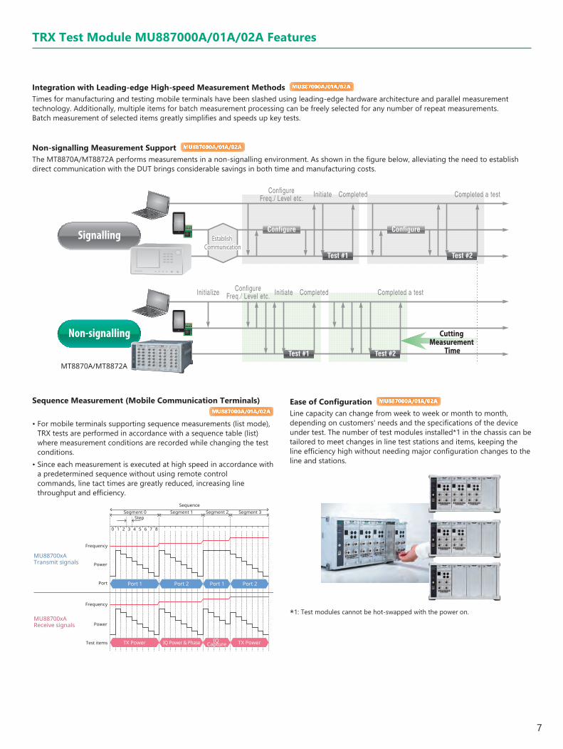
Integration with Leading-edge High-speed Measurement Methods MU887000A/01A/02A
Times for manufacturing and testing mobile terminals have been slashed using leading-edge hardware architecture and parallel measurement technology. Additionally, multiple items for batch measurement processing can be freely selected for any number of repeat measurements. Batch measurement of selected items greatly simplifies and speeds up key tests.
Non-signalling Measurement Support MU887000A/01A/02A
The MT8870A/MT8872A performs measurements in a non-signalling environment. As shown in the figure below, alleviating the need to establish direct communication with the DUT brings considerable savings in both time and manufacturing costs.
Sequence Measurement (Mobile Communication Terminals)MU887000A/01A/02A
• For mobile terminals supporting sequence measurements (list mode), TRX tests are performed in accordance with a sequence table (list) where measurement conditions are recorded while changing the test conditions.
• Since each measurement is executed at high speed in accordance with a predetermined sequence without using remote control commands, line tact times are greatly reduced, increasing line throughput and efficiency.
MT8870A/MT8872A
Signalling
Non-signalling
TRX Test Module MU887000A/01A/02A Features
SequenceSegment 0 Segment 1 Segment 2 Segment 3
Step
10 2 3 4 5 6 7 8
Frequency
Power
Port
Frequency
Power
Test items
MU88700xA Transmit signals
MU88700xA Receive signals
Port 1 Port 2 Port 1 Port 2
TX Power IQ Power & Phase IQ Capture TX Power
Ease of Configuration MU887000A/01A/02A
Line capacity can change from week to week or month to month, depending on customers' needs and the specifications of the device under test. The number of test modules installed*1 in the chassis can be tailored to meet changes in line test stations and items, keeping the line efficiency high without needing major configuration changes to the line and stations.
*1: Test modules cannot be hot-swapped with the power on.

8
TRX Test Module MU887002A Features
12 RF Test Ports MU887002A
The MU887002A has two TRX functions in one module and each TRX function has 12 built-in RF test ports.
Local Oscillator
Local Oscillator
Local Oscillator
Local Oscillator
TRX Test Module MU887002A
Signal Analyzer
Full-duplex(Divider)
Switch
Divider
Signal Generation section
Controlsection
Signal Analysis section
UserInterface
TRX1
Test port 1
Test port 12
.....
.....
..... ......
Signal Generator
Test port 2
Test port 11
Signal Analyzer
Full-duplex(Divider)
Switch
Divider
Signal Generation section
Controlsection
Signal Analysis section
UserInterface
TRX2
Test port 1
Test port 12
.....
.....
...........
Signal Generator
Test port 2
Test port 11
The MU887002A has 12 test ports supporting high level accuracy over a wide range from 400 MHz to 6.0 GHz. Installing the MU887002A-007 option increases the upper frequency of test ports 5 to 12 to 7.3 GHz with a maximum output level of 0 dBm. A built-in divider at the output side supporting simultaneous signal output from all 12 ports facilitates shorter test times by receiving the signal simultaneously at multiple antennas without requiring an external divider (Broadcast function).Measurement is performed by switching the 12 test ports using the internal switch at the input side.
Test Port and Wireless Technology MU887002A
MU887002A
TRX1 Test Ports 1 to 12 TRX2 Test Ports 1 to 12
Connector N (female)
Type (Configuration)
Duplex (divider) Half Duplex (switch)Test port 5 to 12, 5900 MHz ≤ f, when MU887002A-007 installed
OutlineCan use both VSA and VSG required for mobile wireless standard measurements simultaneouslySignal output from all port simultaneously*1
Wireless Standards*2
Supported standards: 5G NR sub-6 GHz, LTE/LTE-Advanced, W-CDMA/HSPA, TD-SCDMA, GSM/EDGE, CDMA2000/1xEV-DO, WLAN 802.11a/b/g/n/p/ac/ax, Bluetooth, GPS, Galileo, GLONASS, BeiDou, DVB-H
*1: The MU887002A-007 is required when f ≥ 6000 MHz, and test ports 5 to 12 support simultaneous output.
*2: See "Measurement Software/Waveforms Ordering Information" for details of support for future expected standards.
9
TRX Test Module MU887002A Features
ANT1
ANT2ANT3
ANT4
TX Cal
TX Cal
RX Cal
RX Cal
RX Cal
RX Cal
ANT1
ANT2ANT3
ANT4
TX Cal
TX Cal
RX Cal
RX Cal
RX Cal
RX Cal
Shorter Times
Time
TimeBroadcasting cal.
DUT1
DUT2
DUT3
DUT4
DUT #1
DUT #2DUT #3
DUT #4
DUT #1
DUT #2DUT #3
DUT #4
RX #1
RX #2
RX #3
RX #4
RX #1
RX #2
RX #3
RX #4Time
Time
Shorter Rx Tests by Simultaneous Receiving at Multiple DUTs using Simultaneous Output Function
Shorter Times
DUT #1
DUT #2DUT #3
DUT #4
DUTControl
RFTesting
#11 #12
#31 #32
#41 #42
Time
Time
DUTControl
Shorter Multiple DUT Tx Test Times using Multi-DUT Measurement Scheduler Function
RFTesting
#11 #21 #31 #41 #12 #22 #32 #42
#21 #22
Shorter Times
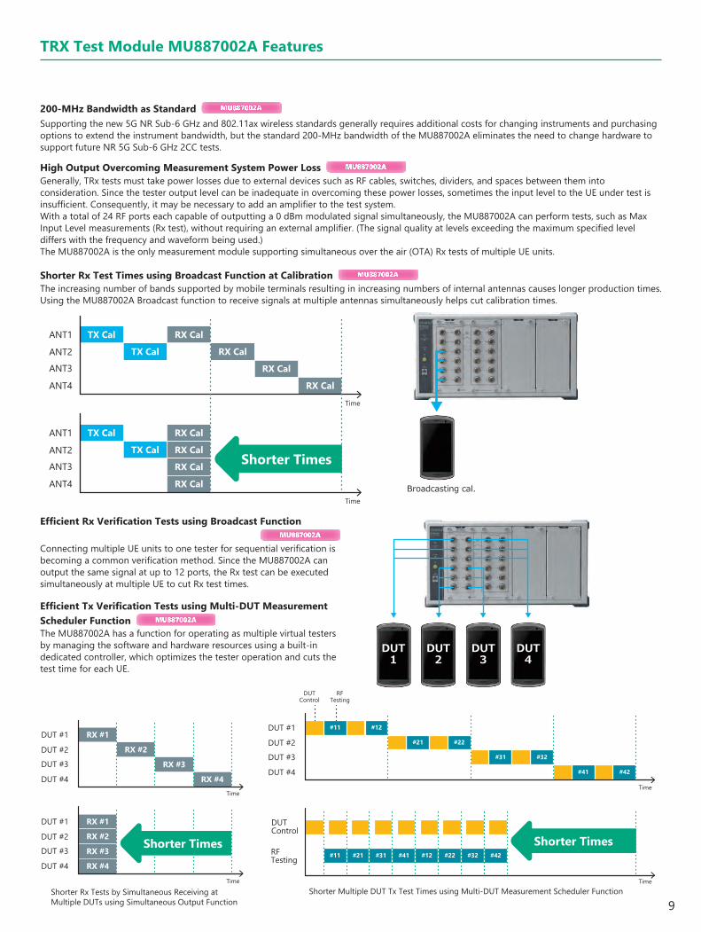
Efficient Rx Verification Tests using Broadcast FunctionMU887002A
Connecting multiple UE units to one tester for sequential verification is becoming a common verification method. Since the MU887002A can output the same signal at up to 12 ports, the Rx test can be executed simultaneously at multiple UE to cut Rx test times.
Efficient Tx Verification Tests using Multi-DUT Measurement Scheduler Function MU887002A
The MU887002A has a function for operating as multiple virtual testers by managing the software and hardware resources using a built-in dedicated controller, which optimizes the tester operation and cuts the test time for each UE.
200-MHz Bandwidth as Standard MU887002A
Supporting the new 5G NR Sub-6 GHz and 802.11ax wireless standards generally requires additional costs for changing instruments and purchasing options to extend the instrument bandwidth, but the standard 200-MHz bandwidth of the MU887002A eliminates the need to change hardware to support future NR 5G Sub-6 GHz 2CC tests.
High Output Overcoming Measurement System Power Loss MU887002A
Generally, TRx tests must take power losses due to external devices such as RF cables, switches, dividers, and spaces between them into consideration. Since the tester output level can be inadequate in overcoming these power losses, sometimes the input level to the UE under test is insufficient. Consequently, it may be necessary to add an amplifier to the test system.With a total of 24 RF ports each capable of outputting a 0 dBm modulated signal simultaneously, the MU887002A can perform tests, such as Max Input Level measurements (Rx test), without requiring an external amplifier. (The signal quality at levels exceeding the maximum specified level differs with the frequency and waveform being used.)The MU887002A is the only measurement module supporting simultaneous over the air (OTA) Rx tests of multiple UE units.
Shorter Rx Test Times using Broadcast Function at Calibration MU887002A
The increasing number of bands supported by mobile terminals resulting in increasing numbers of internal antennas causes longer production times. Using the MU887002A Broadcast function to receive signals at multiple antennas simultaneously helps cut calibration times.
10
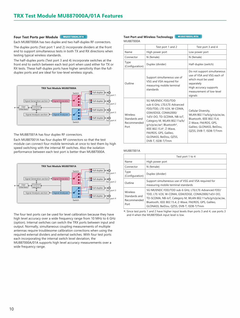
Four Test Ports per Module MU887000A/01A
Each MU887000A has two duplex and two half-duplex RF connectors.The duplex ports (Test port 1 and 2) incorporate dividers at the front end to support simultaneous tests in both TX and RX directions when testing typical wireless standards. The half-duplex ports (Test port 3 and 4) incorporate switches at the front end to switch between each test port when used either for TX or RX tests. These half-duplex ports have higher sensitivity than the full-duplex ports and are ideal for low-level wireless signals.
Signal Generator
Signal Analyzer
Signal Generation section
Controlsection
Signal Analysis section
UserInterface
TRX Test Module MU887000AFull-duplex
Full-duplex
Half-duplex
Half-duplex
Switch
SwitchTest port 1
Test port 2
Test port 3
Test port 4
The four test ports can be used for level calibration because they have high level accuracy over a wide frequency range from 10 MHz to 6 GHz (option). Internal switches can switch the TRX ports between input and output. Normally, simultaneous coupling measurements of multiple antennas require troublesome calibration corrections when using the required external dividers and external switches. With four test ports each incorporating the internal switch level deviation, the MU887000A/01A supports high level accuracy measurements over a wide frequency range.
Test Port and Wireless Technology MU887000A/01A
MU887000A
Test port 1 and 2 Test port 3 and 4
Name High power port Low power port
Connector N (female) N (female)
Type (Configuration)
Duplex (divider) Half-duplex (switch)
Outline
Support simultaneous use of VSG and VSA required for measuring mobile terminal standards
Do not support simultaneous use of VSA and VSG each of which must be used separatelyHigh accuracy supports measurement of low-level signals
Wireless Standards and Recommended Port
5G NR/ENDC FDD/TDD sub-6 GHz, LTE/LTE-Advanced FDD/TDD, LTE-V2X, W-CDMA, GSM/EDGE, CDMA2000/1xEV-DO, TD-SCDMA, NB-IoT, Category M, WLAN 802.11a/b/g/n/p/ac/ax*, Bluetooth*, IEEE 802.15.4*, Z-Wave, FM/RDS, GPS, Galileo, GLONASS, BeiDou, QZSS, DVB-T, ISDB-T/Tmm
Cellular Diversity, WLAN 802.11a/b/g/n/p/ac/ax, Bluetooth, IEEE 802.15.4, Z-Wave, FM/RDS, GPS, Galileo, GLONASS, BeiDou, QZSS, DVB-T, ISDB-T/Tmm
MU887001A
Test port 1 to 4
Name High power port
Connector N (female)
Type (Configuration)
Duplex (divider)
OutlineSupport simultaneous use of VSG and VSA required for measuring mobile terminal standards
Wireless Standards and Recommended Port
5G NR/ENDC FDD/TDD sub-6 GHz, LTE/LTE-Advanced FDD/TDD, LTE-V2X, W-CDMA, GSM/EDGE, CDMA2000/1xEV-DO, TD-SCDMA, NB-IoT, Category M, WLAN 802.11a/b/g/n/p/ac/ax, Bluetooth, IEEE 802.15.4, Z-Wave, FM/RDS, GPS, Galileo, GLONASS, BeiDou, QZSS, DVB-T, ISDB-T/Tmm
*: Since test ports 1 and 2 have higher input levels than ports 3 and 4, use ports 3 and 4 when the MU88700xA input level is low.
Signal Generator
Signal Analyzer
Full-duplex
Full-duplex
Full-duplex
Full-duplex
Switch
Switch
Signal Generation section
Controlsection
Signal Analysis section
UserInterface
TRX Test Module MU887001A
Test port 1
Test port 2
Test port 3
Test port 4
The MU887001A has four duplex RF connectors.Each MU887001A has four duplex RF connectors so that the test module can connect four mobile terminals at once to test them by high speed switching with the internal RF switches. Also the isolation performance between each test port is better than MU887000A.
TRX Test Module MU887000A/01A Features

11
Built-in Audio Analyzer/Audio Generator MU887000A/01A
Installing the Audio Measurement Hardware MU887000A/01A-002 in the MU887000A/01A supports a built-in audio analyzer and audio generator.The MU887000A/01A-002 supports both analog and digital audio. The stereo and monaural analog audio inputs and outputs of a communications device can be measured using the four BNC connectors (input and output for both left and right channels). Additionally, digital audio communications modules without analog audio inputs and outputs are supported without needing an AD/DC converter using the RJ-45 connector on the MU887000A/01A to measure digital audio signals using the standard inter-IC Sound (I2S) format.
TRX Test ModuleMU887000A/01A
Audio Measurement HardwareMU887000A/01A-002
The MU887000A/01A-002 solution saves spaces and cuts costs by combining RF and audio measurements into one unit, eliminating the need for separate production lines for RF measurements and audio measurements.
TRX Test Module MU887000A/01AAudio Measurement Hardware MU887000A/01A-002
Audio Measurement
RF Measurement
*: The audio analyzer and audio generator functions cannot be used simultaneously.
CombiView Audio Measurement Screen
TRX Test Module MU887000A/01A Features
12
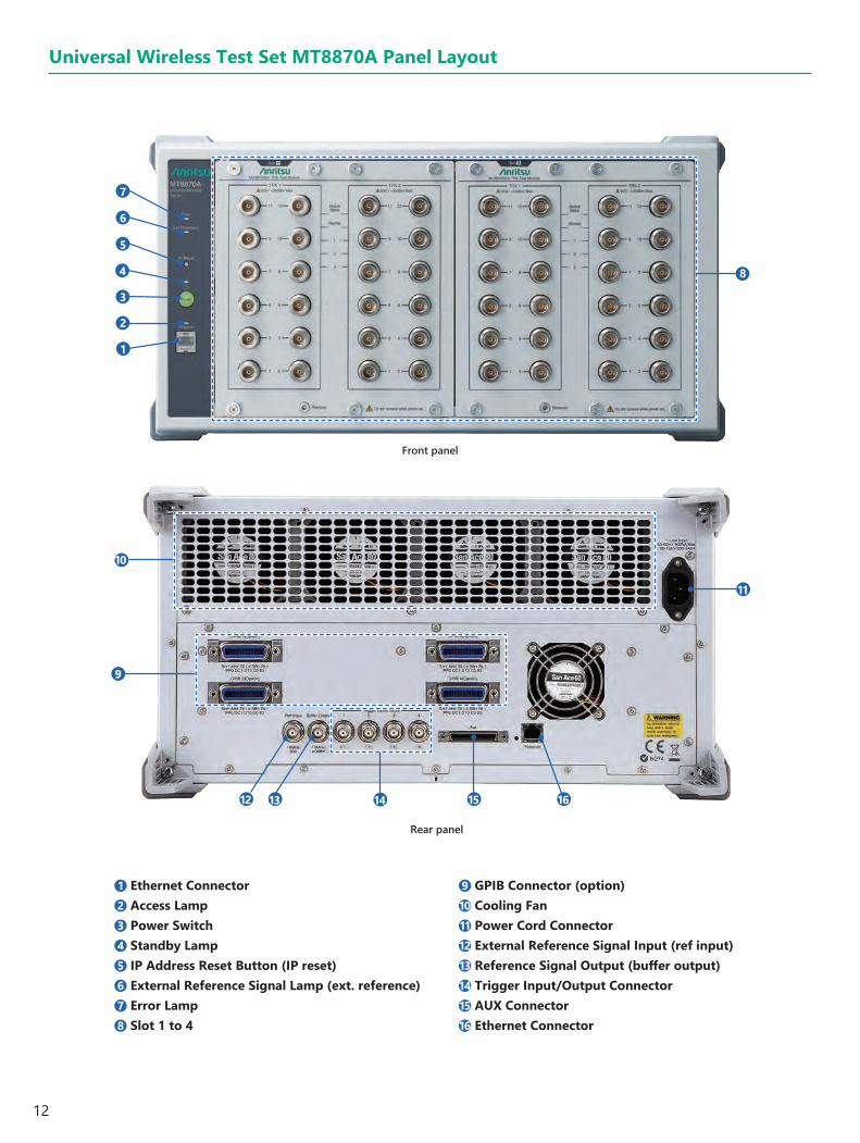
1 Ethernet Connector2 Access Lamp3 Power Switch4 Standby Lamp5 IP Address Reset Button (IP reset)6 External Reference Signal Lamp (ext. reference)7 Error Lamp8 Slot 1 to 4
9 GPIB Connector (option)10 Cooling Fan11 Power Cord Connector12 External Reference Signal Input (ref input)13 Reference Signal Output (buffer output)14 Trigger Input/Output Connector15 AUX Connector16 Ethernet Connector
1
2
3
4
5
6
7
8
11
12 13 14 15 16
9
10
Front panel
Rear panel
Universal Wireless Test Set MT8870A Panel Layout

13
Universal Wireless Test Set MT8872A Panel Layout
1 Ethernet Connector2 Access Lamp3 Power Switch4 Standby Lamp5 IP Address Reset Button (IP Reset)6 External Reference Signal Lamp (Ext. Reference)7 Error Lamp8 Slot 1 to 2
9 GPIB Connector (option)10 Cooling Fan11 Power Cord Connector12 External Reference Signal Input (Ref Input)13 Reference Signal Output (Buffer Output)14 Trigger Input/Output Connector15 AUX Connector16 Ethernet Connector
1
2
3
4
5
6
7
8
9
10
11
1213
14 15 16
Front Panel
Rear Panel

14
TRX Test Module MU887002A Panel
1 Test Ports 1 to 122 Remote Lamps (Remote)3 Status Lamps (Module Status)4 Status Lamps5 TRX 16 TRX 27 Mounting Screws (7)8 Hole for Unmounting Tool (one location)
MU887002A (with MU887002A-007)
MU887002A
1
1
7
7
8
8
2
2
3
3
4
4
5
5
6
6
15
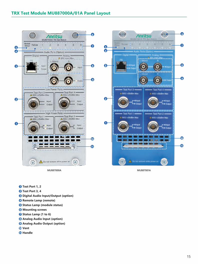
1 Test Port 1, 22 Test Port 3, 43 Digital Audio Input/Output (option)4 Remote Lamp (remote)5 Status Lamp (module status)6 Mounting screws7 Status Lamp (1 to 6)8 Analog Audio Input (option)9 Analog Audio Output (option)10 Vent11 Handle
1
2
3
45
6
7
8
9
10
11
1
2
3
45
6
7
8
9
10
11
MU887000A MU887001A
TRX Test Module MU887000A/01A Panel Layout

16
Recommended ConfigurationModel Description Qty.
MT8870A/MT8872A Universal Wireless Test Set 1
MU88700xA TRX Test Module 1
MX887010A Cellular Standards Sequence Measurement 1
MX887065A Category M FDD Uplink TX Measurement 1
MX887067A NB-IoT Uplink TX Measurement 1
MX887090A Multi-DUT Measurement scheduler 1
MV887065A Category M FDD Downlink Waveforms 1
MV887067A NB-IoT Downlink Waveforms 1
Universal Wireless Test Set MT8870A/MT8872A Applications
Smartphones/AutomotiveSmartphone/Automotive Measurement (Simultaneous Measurement of Multiple Wireless Technologies)
Cellular LPWA DevicesNB-IoT Module Measurement
Two TRX Test Modules can be used to measure multiple wireless technologies in one wireless device or module.The multiple antennas for the various wireless technologies in the wireless device or module are connected all at one time to execute measurements in parallel, greatly reducing the problems of moving smartphones between test stations and re-booting time for smartphone.Recommended Configuration
Model Description Qty.MT8870A/MT8872A Universal Wireless Test Set 1MU88700xA TRX Test Module 1MU88700xA-001* 6 GHz Frequency Extension 1MU88700xA-002* Audio Measurement Hardware 1MX887010A Cellular Standards Sequence Measurement 1MX887013A LTE FDD Uplink TX Measurement 1MX887013A-001 LTE-Advanced FDD Uplink CA TX Measurement 1MX887018A NR FDD sub-6 GHz Uplink Measurement 1MX887018A-001 NR FDD Contiguous ENDC TX Measurement 1MX887019A NR TDD sub-6 GHz Uplink Measurement 1MX887019A-001 NR TDD Contiguous ENDC TX Measurement 1MX887030A WLAN 802.11b/g/a/n TX Measurement 1MX887031A WLAN 802.11ac TX Measurement 1MX887033A WLAN 802.11ax TX Measurement 1MX887040A Bluetooth TX Measurement 1MX887040A-001 DLE TX Measurement 1MX887040A-002 2LE TX Measurement 1MX887040A-003 BLR TX Measurement 1MX887068A LTE-V2X TX Measurement 1MX887070A* FM/Audio TRX Measurement 1MX887090A Multi-DUT Measurement scheduler 1MV887013A LTE FDD Downlink Waveforms 1MV887018A NR FDD sub-6 GHz Downlink Waveforms 1MV887019A NR TDD sub-6 GHz Downlink Waveforms 1MV887030A WLAN 802.11b/g/a/n Waveforms 1MV887031A WLAN 802.11ac Waveforms 1MV887033A WLAN 802.11ax Waveforms 1MV887040A Bluetooth Waveforms 1MV887040A-001 DLE Waveforms 1MV887040A-002 2LE Waveforms 1MV887040A-003 BLR Waveforms 1MV887068A LTE-V2X Waveforms 1MV887070A* FM RDS Waveforms 1MV887100A GPS Waveforms 1MV887100A-002 GPS L5 Waveforms 1MV887101A Galileo Waveforms 1MV887102A GLONASS Waveforms 1MV887103A BeiDou Waveforms 1MV887104A QZSS Waveforms 1
*: Can only install MU887000A/01ARefer to table of Measurement Software/Waveforms Ordering Information for details of support status.
1 2
1 2

17
One TRX Test Module can be used to measure WLAN 802.11b/g/a/n/p/ac, 11ac (Wave 2), 11ax and Bluetooth v5 modules.
Recommended Configuration
Model Description Qty.
MT8870A/MT8872A Universal Wireless Test Set 1
MU88700xA TRX Test Module 1
MU88700xA-001* 6 GHz Frequency Extension 1
MX887030A WLAN 802.11b/g/a/n TX Measurement 1
MX887031A WLAN 802.11ac TX Measurement 1
MX887032A WLAN 802.11p TX Measurement 1
MX887033A WLAN 802.11ax TX Measurement 1
MX887040A Bluetooth TX Measurement 1
MX887040A-001 DLE TX Measurement 1
MX887040A-002 2LE TX Measurement 1
MX887040A-003 BLR TX Measurement 1
MX887090A Multi-DUT Measurement scheduler 1
MV887030A WLAN 802.11b/g/a/n Waveforms 1
MV887031A WLAN 802.11ac Waveforms 1
MV887032A WLAN 802.11p Waveforms 1
MV887033A WLAN 802.11ax Waveforms 1
MV887040A Bluetooth Waveforms 1
MV887040A-001 DLE Waveforms 1
MV887040A-002 2LE Waveforms 1
MV887040A-003 BLR Waveforms 1
*: Can only install MU887000A/01A
Using two TRX Test Modules supports True MIMO measurement of WLAN 802.11n and 11ac 2×2 MIMO modules.
Recommended Configuration
Model Description Qty.
MT8870A/MT8872A Universal Wireless Test Set 1
MU88700xA TRX Test Module 2
MU88700xA-001* 6 GHz Frequency Extension 2
MX887030A WLAN 802.11b/g/a/n TX Measurement 1
MX887031A WLAN 802.11ac TX Measurement 1
MX887090A Multi-DUT Measurement scheduler 1
MV887030A WLAN 802.11b/g/a/n Waveforms 1
MV887031A WLAN 802.11ac Waveforms 1
*: Can only install MU887000A/01A
Universal Wireless Test Set MT8870A/MT8872A Applications
Connectivity DevicesCombo Module Measurement
WLAN 2×2 MIMO Module Measurement (True MIMO)
18
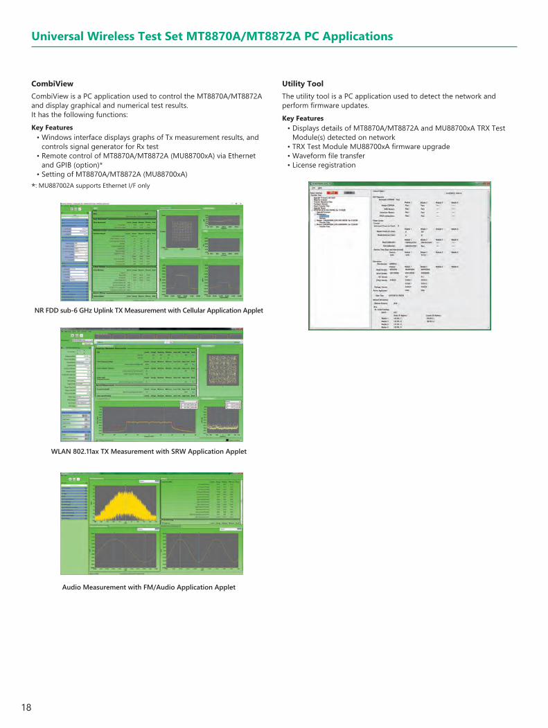
CombiViewCombiView is a PC application used to control the MT8870A/MT8872A and display graphical and numerical test results. It has the following functions:Key Features
• Windows interface displays graphs of Tx measurement results, and controls signal generator for Rx test
• Remote control of MT8870A/MT8872A (MU88700xA) via Ethernet and GPIB (option)*
• Setting of MT8870A/MT8872A (MU88700xA)
*: MU887002A supports Ethernet I/F only
Utility ToolThe utility tool is a PC application used to detect the network and perform firmware updates.Key Features
• Displays details of MT8870A/MT8872A and MU88700xA TRX Test Module(s) detected on network
• TRX Test Module MU88700xA firmware upgrade• Waveform file transfer• License registration
NR FDD sub-6 GHz Uplink TX Measurement with Cellular Application Applet
WLAN 802.11ax TX Measurement with SRW Application Applet
Audio Measurement with FM/Audio Application Applet
Universal Wireless Test Set MT8870A/MT8872A PC Applications
19
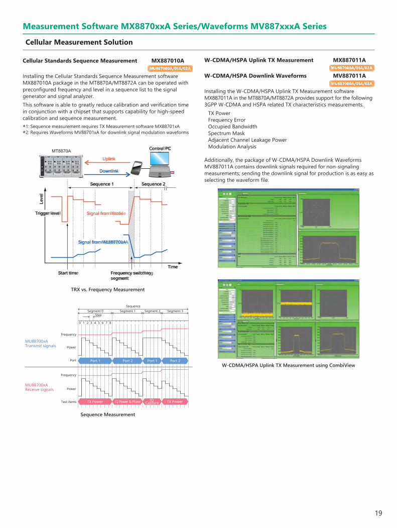
Cellular Standards Sequence Measurement MX887010AMU887000A/01A/02A
Installing the Cellular Standards Sequence Measurement software MX887010A package in the MT8870A/MT8872A can be operated with preconfigured frequency and level in a sequence list to the signal generator and signal analyzer.This software is able to greatly reduce calibration and verification time in conjunction with a chipset that supports capability for high-speed calibration and sequence measurement.
*1: Sequence measurement requires TX Measurement software MX88701xA*2: Requires Waveforms MV88701xA for downlink signal modulation waveforms
W-CDMA/HSPA Uplink TX Measurement MX887011AMU887000A/01A/02A
W-CDMA/HSPA Downlink Waveforms MV887011AMU887000A/01A/02A
Installing the W-CDMA/HSPA Uplink TX Measurement software MX887011A in the MT8870A/MT8872A provides support for the following 3GPP W-CDMA and HSPA related TX characteristics measurements.
TX PowerFrequency ErrorOccupied BandwidthSpectrum MaskAdjacent Channel Leakage PowerModulation Analysis
Additionally, the package of W-CDMA/HSPA Downlink Waveforms MV887011A contains downlink signals required for non-signaling measurements; sending the downlink signal for production is as easy as selecting the waveform file.
TRX vs. Frequency Measurement
Sequence Measurement
Uplink
Downlink
Signal from Mobile
Signal from MU88700xA
Control PC
Trigger level
Leve
l
Time
Sequence 1 Sequence 2
Start time Frequency switching segment
W-CDMA/HSPA Uplink TX Measurement using CombiView
Measurement Software MX8870xxA Series/Waveforms MV887xxxA Series
Cellular Measurement Solution
SequenceSegment 0 Segment 1 Segment 2 Segment 3
Step
10 2 3 4 5 6 7 8
Frequency
Power
Port
Frequency
Power
Test items
MU88700xA Transmit signals
MU88700xA Receive signals
Port 1 Port 2 Port 1 Port 2
TX Power IQ Power & Phase IQ Capture TX Power
20
Measurement Software MX8870xxA Series/Waveforms MV887xxxA Series
Cellular Measurement Solution (continued)
GSM/EDGE Uplink TX Measurement MX887012AMU887000A/01A/02A
GSM/EDGE Downlink Waveforms MV887012AMU887000A/01A/02A
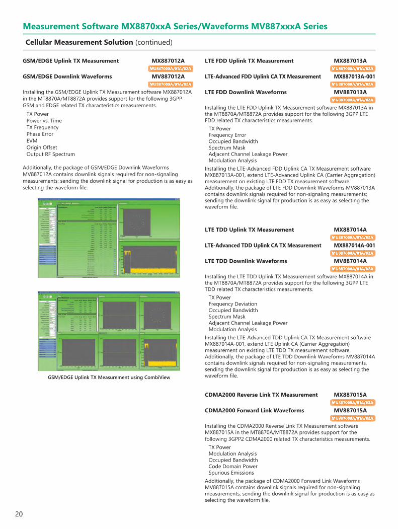
Installing the GSM/EDGE Uplink TX Measurement software MX887012A in the MT8870A/MT8872A provides support for the following 3GPP GSM and EDGE related TX characteristics measurements.
TX PowerPower vs. TimeTX FrequencyPhase ErrorEVMOrigin OffsetOutput RF Spectrum
Additionally, the package of GSM/EDGE Downlink Waveforms MV887012A contains downlink signals required for non-signaling measurements; sending the downlink signal for production is as easy as selecting the waveform file.
LTE FDD Uplink TX Measurement MX887013AMU887000A/01A/02A
LTE-Advanced FDD Uplink CA TX Measurement MX887013A-001MU887000A/01A/02A
LTE FDD Downlink Waveforms MV887013AMU887000A/01A/02A
Installing the LTE FDD Uplink TX Measurement software MX887013A in the MT8870A/MT8872A provides support for the following 3GPP LTE FDD related TX characteristics measurements.
TX PowerFrequency ErrorOccupied BandwidthSpectrum MaskAdjacent Channel Leakage PowerModulation Analysis
Installing the LTE-Advanced FDD Uplink CA TX Measurement software MX887013A-001, extend LTE-Advanced Uplink CA (Carrier Aggregation) measurement on existing LTE FDD TX measurement software. Additionally, the package of LTE FDD Downlink Waveforms MV887013A contains downlink signals required for non-signaling measurements; sending the downlink signal for production is as easy as selecting the waveform file.
GSM/EDGE Uplink TX Measurement using CombiView
LTE TDD Uplink TX Measurement MX887014AMU887000A/01A/02A
LTE-Advanced TDD Uplink CA TX Measurement MX887014A-001MU887000A/01A/02A
LTE TDD Downlink Waveforms MV887014AMU887000A/01A/02A
Installing the LTE TDD Uplink TX Measurement software MX887014A in the MT8870A/MT8872A provides support for the following 3GPP LTE TDD related TX characteristics measurements.
TX PowerFrequency DeviationOccupied BandwidthSpectrum MaskAdjacent Channel Leakage PowerModulation Analysis
Installing the LTE-Advanced TDD Uplink CA TX Measurement software MX887014A-001, extend LTE Uplink CA (Carrier Aggregation) measurement on existing LTE TDD TX measurement software. Additionally, the package of LTE TDD Downlink Waveforms MV887014A contains downlink signals required for non-signaling measurements, sending the downlink signal for production is as easy as selecting the waveform file.
CDMA2000 Reverse Link TX Measurement MX887015AMU887000A/01A/02A
CDMA2000 Forward Link Waveforms MV887015AMU887000A/01A/02A
Installing the CDMA2000 Reverse Link TX Measurement software MX887015A in the MT8870A/MT8872A provides support for the following 3GPP2 CDMA2000 related TX characteristics measurements.
TX PowerModulation AnalysisOccupied BandwidthCode Domain PowerSpurious Emissions
Additionally, the package of CDMA2000 Forward Link Waveforms MV887015A contains downlink signals required for non-signaling measurements; sending the downlink signal for production is as easy as selecting the waveform file.
21
Measurement Software MX8870xxA Series/Waveforms MV887xxxA Series
Cellular Measurement Solution (continued)
1xEV-DO Reverse Link TX Measurement MX887016AMU887000A/01A/02A
1xEV-DO Forward Link Waveforms MV887016AMU887000A/01A/02A
Installing the 1xEV-DO Reverse Link TX Measurement software MX887016A in the MT8870A/MT8872A provides support for the following 3GPP2 CDMA2000 1xEV-DO related TX characteristics measurements.
TX PowerModulation AnalysisOccupied BandwidthCode Domain PowerSpurious Emissions
Additionally, the package of 1xEV-DO Forward Link Waveforms MV887016A contains downlink signals required for non-signaling measurements; sending the downlink signal for production is as easy as selecting the waveform file.
TD-SCDMA Uplink TX Measurement MX887017AMU887000A/01A/02A
TD-SCDMA Downlink Waveforms MV887017AMU887000A/01A/02A
Installing the TD-SCDMA Uplink TX Measurement software MX887017A in the MT8870A/MT8872A provides support for the following 3GPP TD-SCDMA (1.28 Mcps TDD) related TX characteristics measurements.
TX PowerFrequency DeviationOccupied BandwidthSpectrum MaskAdjacent Channel Leakage PowerModulation Analysis
Additionally, the package of TD-SCDMA Downlink Waveforms MV887017A contains downlink signals required for non-signaling measurements, sending the downlink signal for production is as easy as selecting the waveform file.
NR FDD sub-6 GHz Uplink TX Measurement MX887018AMU887000A/01A/02A
NR FDD Contiguous ENDC TX Measurement MX887018A-001MU887000A/01A/02A
NR FDD sub-6 GHz Downlink Waveforms MV887018AMU887000A/01A/02A
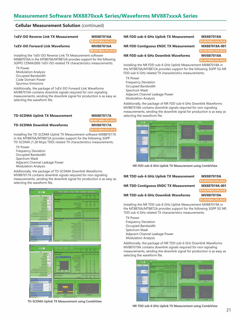
Installing the NR FDD sub-6 GHz Uplink Measurement MX887018A in the MT8870A/MT8872A provides support for the following 3GPP 5G NR FDD sub-6 GHz related TX characteristics measurements.
TX PowerFrequency DeviationOccupied BandwidthSpectrum MaskAdjacent Channel Leakage PowerModulation Analysis
Additionally, the package of NR FDD sub-6 GHz Downlink Waveforms MV887018A contains downlink signals required for non-signaling measurements, sending the downlink signal for production is as easy as selecting the waveform file.
NR TDD sub-6 GHz Uplink TX Measurement MX887019AMU887000A/01A/02A
NR TDD Contiguous ENDC TX Measurement MX887019A-001MU887000A/01A/02A
NR TDD sub-6 GHz Downlink Waveforms MV887019AMU887000A/01A/02A
Installing the NR TDD sub-6 GHz Uplink Measurement MX887019A in the MT8870A/MT8872A provides support for the following 3GPP 5G NR TDD sub-6 GHz related TX characteristics measurements.
TX PowerFrequency DeviationOccupied BandwidthSpectrum MaskAdjacent Channel Leakage PowerModulation Analysis
Additionally, the package of NR TDD sub-6 GHz Downlink Waveforms MV887019A contains downlink signals required for non-signaling measurements, sending the downlink signal for production is as easy as selecting the waveform file.
TD-SCDMA Uplink TX Measurement using CombiView
NR FDD sub-6 GHz Uplink TX Measurement using CombiView
NR TDD sub-6 GHz Uplink TX Measurement using CombiView
22
W-CDMA/HSPA Downlink TX Measurement MX887021AMU887000A/01A
W-CDMA/HSPA Uplink Waveforms MV887021AMU887000A/01A
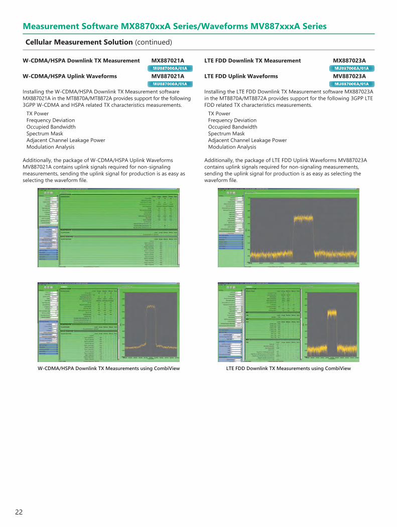
Installing the W-CDMA/HSPA Downlink TX Measurement software MX887021A in the MT8870A/MT8872A provides support for the following 3GPP W-CDMA and HSPA related TX characteristics measurements.
TX PowerFrequency DeviationOccupied BandwidthSpectrum MaskAdjacent Channel Leakage PowerModulation Analysis
Additionally, the package of W-CDMA/HSPA Uplink Waveforms MV887021A contains uplink signals required for non-signaling measurements, sending the uplink signal for production is as easy as selecting the waveform file.
LTE FDD Downlink TX Measurement MX887023AMU887000A/01A
LTE FDD Uplink Waveforms MV887023AMU887000A/01A
Installing the LTE FDD Downlink TX Measurement software MX887023A in the MT8870A/MT8872A provides support for the following 3GPP LTE FDD related TX characteristics measurements.
TX PowerFrequency DeviationOccupied BandwidthSpectrum MaskAdjacent Channel Leakage PowerModulation Analysis
Additionally, the package of LTE FDD Uplink Waveforms MV887023A contains uplink signals required for non-signaling measurements, sending the uplink signal for production is as easy as selecting the waveform file.
W-CDMA/HSPA Downlink TX Measurements using CombiView LTE FDD Downlink TX Measurements using CombiView
Measurement Software MX8870xxA Series/Waveforms MV887xxxA Series
Cellular Measurement Solution (continued)
23
Measurement Software MX8870xxA Series/Waveforms MV887xxxA Series
Cellular-IoT Measurement Solution (Cellular-LPWA Solution)
NB-IoT Uplink TX Measurement MX887067AMU887000A/01A
NB-IoT Downlink Waveforms MV887067AMU887000A/01A
Installing the NB-IoT Uplink TX Measurement software MX887067A in the MT8870A/MT8872A provides support for the following 3GPP LTE NB-IoT related TX characteristics measurements.
TX PowerFrequency ErrorOccupied BandwidthSpectrum MaskAdjacent Channel Leakage PowerModulation Analysis
Additionally, the package of NB-IoT Downlink Waveforms MV887067A contains downlink signals required for non-signaling measurements; sending the downlink signal for production is as easy as selecting the waveform file.
Category M FDD Uplink TX Measurement MX887065AMU887000A/01A
Category M FDD Downlink Waveforms MV887065AMU887000A/01A
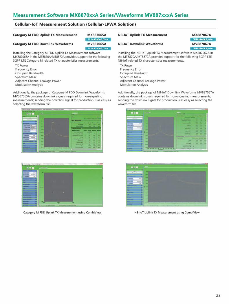
Installing the Category M FDD Uplink TX Measurement software MX887065A in the MT8870A/MT8872A provides support for the following 3GPP LTE Category M related TX characteristics measurements.
TX PowerFrequency ErrorOccupied BandwidthSpectrum MaskAdjacent Channel Leakage PowerModulation Analysis
Additionally, the package of Category M FDD Downlink Waveforms MV887065A contains downlink signals required for non-signaling measurements; sending the downlink signal for production is as easy as selecting the waveform file.
NB-IoT Uplink TX Measurement using CombiViewCategory M FDD Uplink TX Measurement using CombiView

24
WLAN 802.11b/g/a/n TX Measurement MX887030A MU887000A/01A/02A WLAN 802.11b/g/a/n Waveforms MV887030A MU887000A/01A/02A
The MT8870A/MT8872A/MU88700xA supports non-signalling transmitter and receiver tests for all WLAN 802.11b/g/a/n-compliant devices. Requires installation of 6 GHz Frequency Expansion MU887000A/01-001 option (sold separately) when measuring 5-GHz band IEEE 802.11a/n using MU887000A/01A.
Transmitter TestInstalling the MX887030A in the MT8870A/MT8872A provides support for measurement of key IEEE 802.11 - March 2012 : 802.11b TX Test using all installed TRX test modules.802.11b TX Measurement
802.11g/a/n TX Measurement
IEEE 802.11 TX characteristics802.11b Test Items
17.4.7.2 Transmit Power Levels17.4.7.3 Transmit Power Level Control17.4.7.4 Transmit Spectrum Mask17.4.7.5 Transmit Center Frequency Tolerance17.4.7.6 Chip Clock Frequency Tolerance17.4.7.7 Transmit power-on and power-down ramp17.4.7.8 RF Carrier Suppression17.4.7.9 Transmit Modulation Accuracy
Additional 802.11b Measurements Test Items
Power crest factorCCDFIQ offsetPhase & magnitude errorOccupied bandwidthPower spectral density
IEEE 802.11a/g/n TX Test802.11a 802.11g 802.11n Test Items
18.3.9.2 19.4.8.2 20.3.20.3 Transmit Power Levels18.3.9.3 19.5.5 20.3.20.1 Transmit Spectrum Mask18.3.9.5 19.4.8.3 20.3.20.4 Transmit center frequency tolerance18.3.9.6 19.4.8.4 20.3.20.6 Symbol Clock frequency tolerance18.3.9.7.2 19.4.8 (18.3.9.7.2) 20.3.20.7.2 Transmitter center frequency leakage18.3.9.7.3 19.4.8 (18.3.9.7.3) 20.3.20.2 Transmitter spectral flatness18.3.9.7.4 19.4.8 (18.3.9.7.4) 20.3.20.7.3 Transmitter constellation error18.3.9.8 19.4.8 (18.3.9.8) 20.3.20.7.4 Transmitter modulation accuracy test
Additional 802.11g/a/n MeasurementsTest Items
Power crest factorCCDFOccupied bandwidthPower spectral density
Measurement Software MX8870xxA Series/Waveforms MV887xxxA Series
WLAN Measurement Solution
Receiver TestThe MV887030A application provides support for transmission of WLAN 802.11b/g/a/n signals from the vector signal generator to the device under test (DUT). The number of received packets can then be read using the chipset vendor's control software.
TRX Test Module
Waveform memory
Signal generator
WLAN moduleWLAN 802.11b/g/a/n WaveformsMV887030A
RFRF
WLAN 802.11b/g/a/n WaveformsMV887030A
Waveform memory
Signal generator
Waveform Parameter802.11 Standard Data Rate/Modulation Bandwidth Packet Length Remarks
802.11b 11, 5.5, 2, 1 Mbps – 1024 or 100 bytes Long preamble802.11a/g 54, 48, 36, 24, 18, 12, 9 and 6 Mbps – 1000 or 100 bytes802.11n MCS 0 to 7 and 32 20 MHz and 40 MHz 4096 or 500 bytes Nss: 1, Guard interval: Long
802.11b RX MeasurementIEEE 802.11b RX Test
802.11b Test Items17.4.8.2 Receiver minimum input level sensitivity17.4.8.3 Receiver maximum input level
802.11g/a/n RX MeasurementIEEE 802.11a/g/n RX Test
802.11a 802.11g 802.11n Test Items18.3.10.2 19.5.2 20.3.21.1 Receiver minimum input level sensitivity18.3.10.5 19.5.4 20.3.21.4 Receiver maximum input level

25
Measurement Software MX8870xxA Series/Waveforms MV887xxxA Series
WLAN Measurement Solution
WLAN 802.11ac TX Measurement MX887031A MU887000A/01A/02A WLAN 802.11ac Waveforms MV887031A MU887000A/01A/02A
The MT8870A/MT8872A/MU88700xA supports non-signalling transmitter and receiver tests for all WLAN 802.11ac-compliant devices. The 6 GHz Frequency Extension option MU887000A/01A-001 is required when using MU887000A/01A.
Transmitter TestInstalling the WLAN 802.11ac TX Measurement software MX887031A in the MT8870A/MT8872A supports in-band wireless measurements defined by the IEEE 802.11ac on all installed TRX test modules.
802.11ac TX MeasurementIEEE 802.11ac TX Test
802.11ac Test Items
22.3.18.1 Transmit spectrum mask
22.3.18.2 Spectral flatness
22.3.18.3 Transmit center frequency tolerance
22.3.18.3 Symbol Clock frequency tolerance
22.3.18.4 Modulation accuracy
22.3.18.4.2 Transmitter center frequency leakage
22.3.18.4.3 Transmitter constellation error
22.3.18.4.4 Transmitter modulation accuracy (EVM) test
Transmit power level
Additional 802.11ac Measurements
Test Items
Power crest factor
CCDF
Occupied bandwidth
Power spectral density
Receiver TestThe MV887031A application provides support for transmission of WLAN 802.11ac signals from the vector signal generator to the device under test. The number of received packets can then be read using the chipset vendor's control software.
WLAN moduleWLAN 802.11ac WaveformsMV887031A
RFRF
WLAN 802.11ac WaveformsMV887031A
Waveform memory
Signal generator
Waveform memory
Signal generator
TRX Test Module
Waveform Parameter
802.11 Standard Data Rate/Modulation Bandwidth Packet Length Remarks
802.11ac MCS 0 to 9 20, 40, 80, 160 MHz 4096 or 500 bytes Nss: 1, Guard interval: Long
802.11ac RX MeasurementIEEE 802.11ac RX Test
802.11ac Test Items
22.3.19.1 Receiver minimum input level sensitivity
22.3.19.4 Receiver maximum input level
26
Measurement Software MX8870xxA Series/Waveforms MV887xxxA Series
V2X Measurement Solution
WLAN 802.11p TX Measurement MX887032A MU887000A/01A/02A WLAN 802.11p Waveforms MV887032A MU887000A/01A/02A
The MT8870A/MT8872A/MU88700xA supports non-signalling TRX tests for all WLAN 802.11p-compliant communications devices. The 6 GHz Frequency Extension option MU887000A/01A-001 is required to measure 802.11p in 5.9 GHz band when using MU887000A/01A.
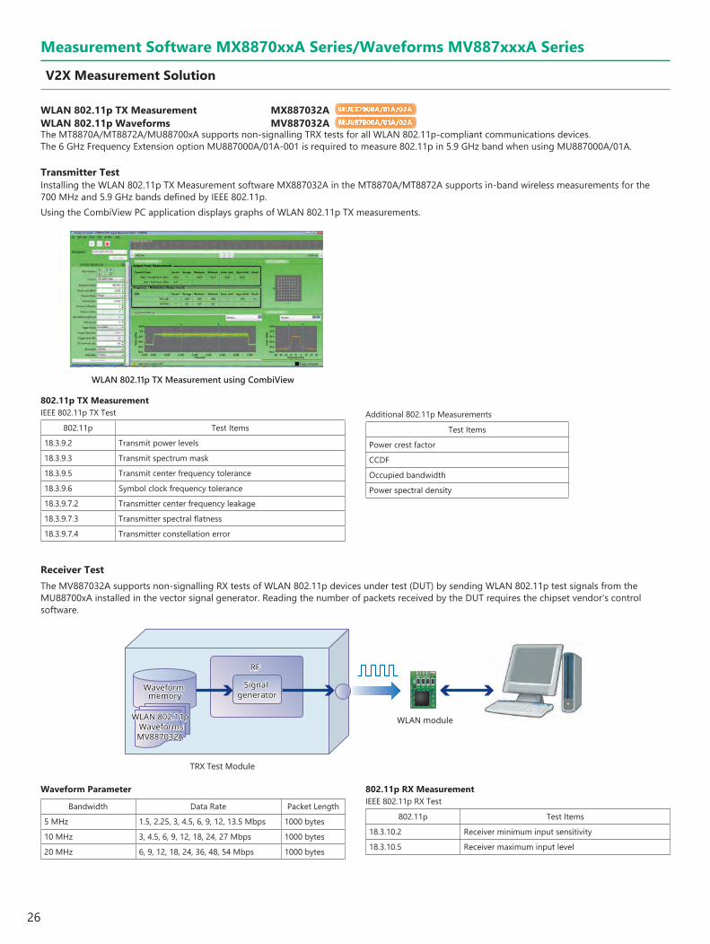
Transmitter TestInstalling the WLAN 802.11p TX Measurement software MX887032A in the MT8870A/MT8872A supports in-band wireless measurements for the 700 MHz and 5.9 GHz bands defined by IEEE 802.11p.Using the CombiView PC application displays graphs of WLAN 802.11p TX measurements.
WLAN 802.11p TX Measurement using CombiView
802.11p TX MeasurementIEEE 802.11p TX Test
802.11p Test Items
18.3.9.2 Transmit power levels
18.3.9.3 Transmit spectrum mask
18.3.9.5 Transmit center frequency tolerance
18.3.9.6 Symbol clock frequency tolerance
18.3.9.7.2 Transmitter center frequency leakage
18.3.9.7.3 Transmitter spectral flatness
18.3.9.7.4 Transmitter constellation error
Additional 802.11p Measurements
Test Items
Power crest factor
CCDF
Occupied bandwidth
Power spectral density
Receiver TestThe MV887032A supports non-signalling RX tests of WLAN 802.11p devices under test (DUT) by sending WLAN 802.11p test signals from the MU88700xA installed in the vector signal generator. Reading the number of packets received by the DUT requires the chipset vendor's control software.
WLAN moduleWLAN 802.11p WaveformsMV887032A
RFRF
WLAN 802.11p WaveformsMV887032A
Waveform memory
Signal generator
Waveform memory
Signal generator
TRX Test Module
Waveform Parameter
Bandwidth Data Rate Packet Length
5 MHz 1.5, 2.25, 3, 4.5, 6, 9, 12, 13.5 Mbps 1000 bytes
10 MHz 3, 4.5, 6, 9, 12, 18, 24, 27 Mbps 1000 bytes
20 MHz 6, 9, 12, 18, 24, 36, 48, 54 Mbps 1000 bytes
802.11p RX MeasurementIEEE 802.11p RX Test
802.11p Test Items
18.3.10.2 Receiver minimum input sensitivity
18.3.10.5 Receiver maximum input level

27
Measurement Software MX8870xxA Series/Waveforms MV887xxxA Series
V2X Measurement Solution
LTE-V2X Tx Measurement using CombiView
LTE-V2X Tx Measurement MX887068A MU887000A/01A LTE-V2X Waveforms MV887068A MU887000A/01A
LTE-V2X Tx characteristics specified by 3GPP can be measured by installing the LTE-V2X Tx Measurement MX887068A software.
Tx PowerFrequency DeviationOccupied Frequency BandwidthSpectrum Emission MaskAdjacent Channel Leakage PowerModulation Analysis
In addition, the bundled LTE-V2X Waveforms MV887068A package includes general RF test signal waveform files required for non-signaling manufacturing for easy output of RF test signals at manufacturing simply by selecting the waveform file.

28
WLAN 802.11n/11ac MIMO Measurement Function MU887000A/01A
Installing the MU88700xA*1 in the MT8870A/MT8872A with the installed WLAN TRX Measurement software supports easy set-up and measurement of up to 4×4 WLAN MIMO devices.
*1: Requires 6 GHz Frequency Extension option MU887000A/01A-001 when measuring WLAN 802.11n (5 GHz) or 802.11ac
Normally, measuring each antenna of a MIMO device (streaming) requires a system set-up composed of up to four measuring instruments of the same type as well as synchronized timing of the signal generators required for MIMO measurement and the 10-MHz reference signal generators, plus complex cable connections to control each measuring instrument.This type of system set-up is not only troublesome for technicians performing MIMO measurements, but also wastes man hours and money. Integrating the MU88700xA into the MT8870A/MT8872A main frame solves the problems of synchronizing signals over external cables experienced with conventional MIMO measurement systems to simplify system set-up and slash time and costs.
The MX887030A and MV887030A are required for WLAN 802.11n MIMO measurements.The MX887031A and MV887031A are required for WLAN 802.11ac MIMO measurements*2.
*2: Supports up to 4×4 MIMO WLAN 802.11ac measurements
SISO
SequentialMIMO
CompositeMIMO
SISO
SequentialMIMO
CompositeMIMO
SISO
SequentialMIMO
CompositeMIMO
2 × 2 True MIMO
3 × 3 True MIMO
4 × 4 True MIMO
2 × 2 True MIMO
3 × 3 True MIMO
4 × 4 True MIMO
4×4 DUT4×4 DUT
Traditional Test SetUniversal Wireless Test Set
MT8870A
MIMO Measurement SolutionsThe MT8870A/MT8872A is the ideal MIMO measurement solution for WLAN MIMO devices at every stage from R&D to production.
True MIMO MU887000A/01A
FeaturesThe MT8870A/MT8872A supports parallel measurement of WLAN device streaming characteristics using multiple MU88700xA units installed in the main frame.It is ideal for performing streaming measurements from each antenna under conditions closely mimicking a real usage environment at the R&D and design stages. There is no need for troublesome external cable connections, because the timing of each MU88700xA unit and the 10-MHz reference frequency are synchronized by the internal connections, offering easy True MIMO measurement.
Transmitter Test• DUT transmits four MIMO signals simultaneously.• MU88700xA in each slot tests each antenna (stream)• Fully independent measurements with parallel processing by
each MU88700xA• Test results
Each TX power (Cross power), EVM, Spectral mask, etc.
VSA VSA VSA VSA
Ant1 Ant2 Ant3 Ant4
SS1
SS2
SS3
SS4
Test sequence:
Antenna 1Antenna 2Antenna 3Antenna 4
Test results:Antenna 1: EVM_1, Power_1, Spectral mask_1 ...Antenna 2: EVM_2, Power_2, Spectral mask_2 ...Antenna 3: EVM_3, Power_3, Spectral mask_3 ...Antenna 4: EVM_4, Power_4, Spectral mask_4 ...
Receiver Test• Sends test packets for each antenna to TRX Test Module in each slot• Test results
RX sensitivity of each antenna• Synchronization
10-MHz reference frequency Digital timing
Note: RF local frequency sync. not supported
VSG VSG VSG VSG
Ant1 Ant2 Ant3 Ant4
SS1
SS2
SS3
SS4
All spatial streams must be synchoronized to the start of the packet.
Product Development
Design Validation
Production Prototyping
Mass Production
True MIMO
Sequential MIMO
Composite MIMO
Measurement Software MX8870xxA Series/Waveforms MV887xxxA Series
WLAN MIMO Measurement Solution

29
Sequential MIMO MU887000A/01A
FeaturesWLAN device MIMO measurements at R&D design require stream measurements from each antenna. Although True MIMO measurement supports an environment in which each antenna is measured simultaneously in parallel, the cost is high because multiple MU88700xA units are required. Since one MU88700xA can support up to four test ports, the Sequential MIMO measurement functions helps cut costs by switching between antennas to perform accurate sequential measurement of each antenna of the MIMO device.
Transmitter Test• DUT transmits four MIMO signals simultaneously• MT8870A/MT8872A switches connected test port and performs TRX
test at each antenna (stream)• Test results
Each TX power (Cross power*3), EVM, Spectral mask, etc.
*3: There are limitation on the combination of test ports used for cross power measurements.
Composite MIMO MU887000A/01A
FeaturesProduction-line operators urgently need ways to cut production costs by shortening tact times through reduced measurement times. MIMO device measurement methods currently focus on measuring each antenna one-by-one but viewed from the perspective of reduced tact time and lower costs, production lines could achieve better efficiency and profits with one single measurement of all MIMO device antennas instead of separate measurements of all antennas (total streaming). Installing the MT8870A/MT8872A with one MU88700xA supports use of the Composite MIMO measurement function to measure WLAN RF characteristics at one time by combining and dividing multiple MIMO signals using an external divider (combiner)*.
*: Recommended productMini-Circuits, ZN4PD1-63 + (Frequency range: 2000 MHz to 6000 MHz)
Transmitter Test• DUT transmits three MIMO signals simultaneously• MT8870A/MT8872A receives composite test signal via divider
(combiner), which combines each streaming MIMO signal output from each antenna, and evaluates RF characteristics
• Test results Composite power (individual powers) Composite EVM and spectral mask values
VSA
Ant1 Ant2 Ant3 Ant4
SS1SS2
SS3SS4
Test sequence:
Antenna 1Antenna 2
Antenna 3Antenna 4
Test results:Antenna 1: EVM_1, Power_1, Spectral mask_1 ...Antenna 2: EVM_2, Power_2, Spectral mask_2 ...Antenna 3: EVM_3, Power_3, Spectral mask_3 ...Antenna 4: EVM_4, Power_4, Spectral mask_4 ...
Receiver Test• MT8870A/MT8872A switches test port and sends test signal to each
antenna to perform RX sensitivity test• Waveform uses SISO signal• Test results
RX test for each antenna Receiver Test• Diversity test (SISO signal)• Transmits test signal from MT8870A/MT8872A and splits into
identical signals at divider (combiner) for input to each antenna• Since same signal received by multiple antennas, performs better
evaluation than RX sensitivity results obtained from one antenna• Test results
RX sensitivity (result is one value only; test specifications of sensitivity changed by number of antennas)
VSG
Ant1 Ant2 Ant3 Ant4
MCS7MCS7
MCS7MCS7
VSA
Divider
Composite signal
SS2
SS1
SS4
SS3
Ant1 Ant2 Ant3 Ant4
Test sequence:
Composite
Test results:EVM_Avg, Power_Avg, Spectral mask_Avg ...
VSG
Divider
MCS7
MCS
7
MCS
7
MCS
7
MCS
7
Ant1 Ant2 Ant3 Ant4
Measurement Software MX8870xxA Series/Waveforms MV887xxxA Series
WLAN MIMO Measurement Solution (continued)
30
Measurement Software MX8870xxA Series/Waveforms MV887xxxA Series
WLAN Measurement Solution
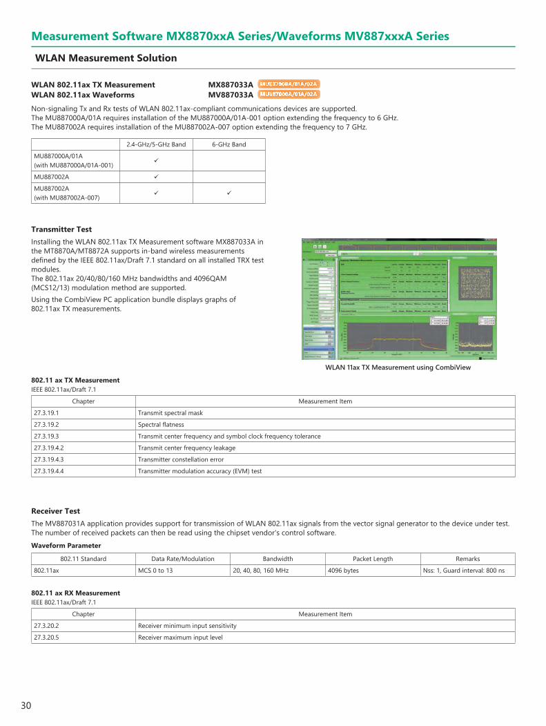
WLAN 802.11ax TX Measurement MX887033A MU887000A/01A/02A WLAN 802.11ax Waveforms MV887033A MU887000A/01A/02A
Non-signaling Tx and Rx tests of WLAN 802.11ax-compliant communications devices are supported.The MU887000A/01A requires installation of the MU887000A/01A-001 option extending the frequency to 6 GHz.The MU887002A requires installation of the MU887002A-007 option extending the frequency to 7 GHz.
2.4-GHz/5-GHz Band 6-GHz Band
MU887000A/01A(with MU887000A/01A-001)
MU887002A
MU887002A(with MU887002A-007)
WLAN 11ax TX Measurement using CombiView
Transmitter TestInstalling the WLAN 802.11ax TX Measurement software MX887033A in the MT8870A/MT8872A supports in-band wireless measurements defined by the IEEE 802.11ax/Draft 7.1 standard on all installed TRX test modules. The 802.11ax 20/40/80/160 MHz bandwidths and 4096QAM (MCS12/13) modulation method are supported.Using the CombiView PC application bundle displays graphs of 802.11ax TX measurements.
802.11 ax TX MeasurementIEEE 802.11ax/Draft 7.1
Chapter Measurement Item
27.3.19.1 Transmit spectral mask
27.3.19.2 Spectral flatness
27.3.19.3 Transmit center frequency and symbol clock frequency tolerance
27.3.19.4.2 Transmit center frequency leakage
27.3.19.4.3 Transmitter constellation error
27.3.19.4.4 Transmitter modulation accuracy (EVM) test
Receiver TestThe MV887031A application provides support for transmission of WLAN 802.11ax signals from the vector signal generator to the device under test. The number of received packets can then be read using the chipset vendor's control software.Waveform Parameter
802.11 Standard Data Rate/Modulation Bandwidth Packet Length Remarks
802.11ax MCS 0 to 13 20, 40, 80, 160 MHz 4096 bytes Nss: 1, Guard interval: 800 ns
802.11 ax RX MeasurementIEEE 802.11ax/Draft 7.1
Chapter Measurement Item
27.3.20.2 Receiver minimum input sensitivity
27.3.20.5 Receiver maximum input level

31
Measurement Software MX8870xxA Series/Waveforms MV887xxxA Series
Bluetooth Measurement Solution
Bluetooth TX Measurement MX887040A MU887000A/01A/02A DLE TX Measurement MX887040A-001 MU887000A/01A/02A 2LE TX Measurement MX887040A-002 MU887000A/01A/02A BLR TX Measurement MX887040A-003 MU887000A/01A/02A Bluetooth Waveforms MV887040A MU887000A/01A/02A DLE Waveforms MV887040A-001 MU887000A/01A/02A 2LE Waveforms MV887040A-002 MU887000A/01A/02A BLR Waveforms MV887040A-003 MU887000A/01A/02A
The MT8870A/MT8872A/MU88700xA supports non-signalling transmitter and receiver tests for Basic Rate (BR), Enhanced Data Rate (EDR) and Bluetooth low-energy (BLE) devices.
Bluetooth TX Measurement using CombiView
Transmitter TestThe Bluetooth TX Measurement software MX887040A has two Bluetooth TX test modes. The SIG Standard mode measures TX test packets sent from the device under test according to the Bluetooth RF Test Specifications. In SIG standard mode, the system returns only measurements that are compatible with the payload type of the captured packets. In Speed Test mode, the system returns results for all enabled measurements regardless of the packet payload.Because the Speed Test mode supports all BR/EDR measurements for individual packet types, it is ideal for rapid testing on production lines.
Bluetooth TX MeasurementBasic Rate and Enhanced Data Rate (EDR)Basic Rate measurements and Enhanced Data Rate measurements made in compliance with Bluetooth RF Test Specification RF.TS.P30
Specification Measurement ItemRF/TRM/CA/BV-01-C [Output Power]RF/TRM/CA/BV-03-C [Power Control]RF/TRM/CA/BV-05-C [TX Output Spectrum – 20 dB Bandwidth]RF/TRM/CA/BV-06-C [TX Output Spectrum – Adjacent Channel Power]RF/TRM/CA/BV-07-C [Modulation Characteristics]RF/TRM/CA/BV-08-C [Initial Carrier Frequency Tolerance]RF/TRM/CA/BV-09-C [Carrier Frequency Drift]RF/TRM/CA/BV-10-C [EDR Relative Transmit Power]RF/TRM/CA/BV-11-C [EDR Carrier Frequency Stability and Modulation Accuracy]RF/TRM/CA/BV-12-C [EDR Differential Phase Encoding]RF/TRM/CA/BV-13-C [EDR In-band Spurious Emissions]*1
RF/TRM/CA/BV-14-C [Enhanced Power Control]RF/TRM/CA/BV-15-C [EDR Guard Time]
*1: Can measure up to ±5 channelsBluetooth Low EnergyBluetooth low energy measurements made in compliance with Bluetooth RF Test Specification RF-PHY.TS.P15
Specification Measurement ItemRequired Option
MX887040A-001 MX887040A-002 MX887040A-003RF-PHY/TRM/BV-01-C [Output power] *3
RF-PHY/TRM/BV-03-C [In-band emissions, uncoded data at 1 Ms/s]*2 *3
RF-PHY/TRM/BV-05-C [Modulation Characteristics, uncoded data at 1 Ms/s] *3
RF-PHY/TRM/BV-06-C [Carrier frequency offset and drift, uncoded data at 1 Ms/s] *3
RF-PHY/TRM/BV-08-C [In-band emissions at 2 Ms/s]*2
RF-PHY/TRM/BV-09-C [Stable Modulation Characteristics, uncoded data at 1 Ms/s] *3
RF-PHY/TRM/BV-10-C [Modulation Characteristics at 2 Ms/s]
RF-PHY/TRM/BV-11-C [Stable Modulation Characteristics at 2 Ms/s]
RF-PHY/TRM/BV-12-C [Carrier frequency offset and drift at 2 Ms/s]
RF-PHY/TRM/BV-13-C [Modulation Characteristics, LE Coded (S = 8)]
RF-PHY/TRM/BV-14-C [Carrier frequency offset and drift, LE Coded (S = 8)]
*2: Can measure BLE: ±5 channels, and 2LE: ±8 channels*3: Required when measuring signal with PSDU Length >37 bytes
Graphical Displays (BR/BLE)Graphs
Power Burst profileFrequency deviationEye diagramSpectral profile
Graphical Displays (EDR)Power burst profileFrequency deviationIQ constellation diagramDEVM against symbolVector diagramSpectral profile

32
Receiver TestThe MV887040A application provides support for transmission of Bluetooth signals from the vector signal generator to the device under test. The number of received packets can then be read using the chipset vendor's control software.
Bluetooth moduleBluetooth WaveformsMV887040A
RFRF
Bluetooth WaveformsMV887040A
Waveform memory
Signal generator
Waveform memory
Signal generator
TRX Test Module
Standard Waveforms
Bluetooth Waveform TypeBasic Rate (BR) DH1/DH3/DH5Enhanced Data Rate (EDR) 2-DH1/2-DH3/2-DH5/3-DH1/3-DH3/3-DH5Bluetooth Low Energy (BLE) BLE/PER Report Integrity TestOthers GFSK/PSK CW (Interference Waveform)
Bluetooth RX MeasurementBasic Rate and Enhanced Data Rate (EDR)Basic Rate measurements and Enhanced Data Rate measurements made in compliance with Bluetooth RF Test Specification RF.TS.P30
Specification Measurement ItemRF/RCV/CA/BV-01-C [Sensitivity – single slot packets]RF/RCV/CA/BV-02-C [Sensitivity - multi-slot packets]RF/RCV/CA/BV-06-C [Maximum Input Level]RF/RCV/CA/BV-07-C [EDR Sensitivity]RF/RCV/CA/BV-08-C [EDR BER Floor Performance]RF/RCV/CA/BV-10-C [EDR Maximum Input Level]
Bluetooth Low EnergyBluetooth low energy measurements made in compliance with Bluetooth RF Test Specification RF-PHY.TS.P15
Specification Measurement ItemRequired Option
MV887040A-001 MV887040A-002 MV887040A-003RF-PHY/RCV/BV-01-C [Receiver sensitivity, uncoded data at 1 Ms/s] *RF-PHY/RCV/BV-06-C [Maximum input signal level, uncoded data at 1 Ms/s] *RF-PHY/RCV/BV-07-C [PER Report Integrity, uncoded data at 1 Ms/s] *RF-PHY/RCV/BV-08-C [Receiver sensitivity at 2 Ms/s]
RF-PHY/RCV/BV-12-C [Maximum input signal level at 2 Ms/s]
RF-PHY/RCV/BV-13-C [PER Report Integrity at 2 Ms/s]
RF-PHY/RCV/BV-14-C [Receiver Sensitivity, uncoded data at 1 Ms/s, Stable Modulation Index] *RF-PHY/RCV/BV-18-C [Maximum input signal level, uncoded data at 1 Ms/s, Stable Modulation Index] *RF-PHY/RCV/BV-19-C [PER Report Integrity, uncoded data at 1 Ms/s, Stable Modulation Index] *RF-PHY/RCV/BV-20-C [Receiver sensitivity at 2 Ms/s, Stable Modulation Index]
RF-PHY/RCV/BV-24-C [Maximum input signal level at 2 Ms/s, Stable Modulation Index]
RF-PHY/RCV/BV-25-C [PER Report Integrity at 2 Ms/s, Stable Modulation Index]
RF-PHY/RCV/BV-26-C [Receiver sensitivity, LE Coded (S = 2)]
RF-PHY/RCV/BV-27-C [Receiver sensitivity, LE Coded (S = 8)]
RF-PHY/RCV/BV-30-C [PER Report Integrity, LE Coded (S = 2)]
RF-PHY/RCV/BV-31-C [PER Report Integrity, LE Coded (S = 8)]
RF-PHY/RCV/BV-32-C [Receiver sensitivity, LE Coded (S = 2), Stable Modulation Index]
RF-PHY/RCV/BV-33-C [Receiver sensitivity, LE Coded (S = 8), Stable Modulation Index]
RF-PHY/RCV/BV-36-C [PER Report Integrity, LE Coded (S = 2), Stable Modulation Index]
RF-PHY/RCV/BV-37-C [PER Report Integrity, LE Coded (S = 8), Stable Modulation Index]
*: Required when measuring signal with PSDU Length >37 bytes
Measurement Software MX8870xxA Series/Waveforms MV887xxxA Series
Bluetooth Measurement Solution (continued)
33
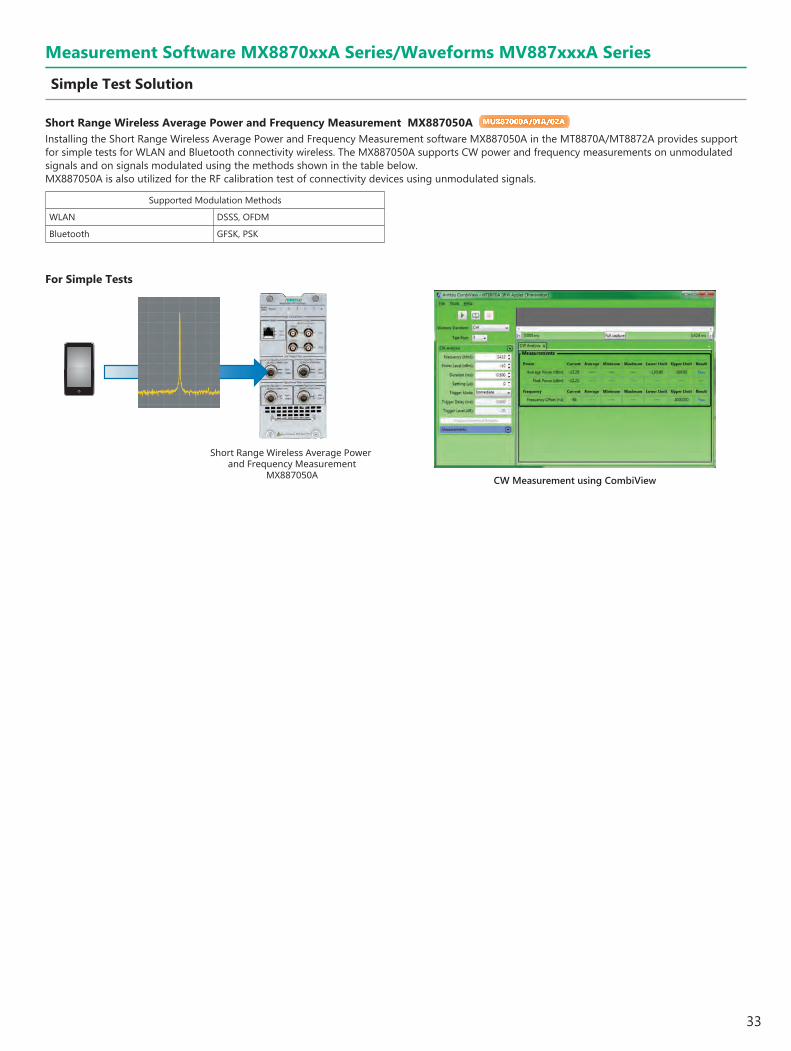
Short Range Wireless Average Power and Frequency Measurement MX887050A MU887000A/01A/02A
Installing the Short Range Wireless Average Power and Frequency Measurement software MX887050A in the MT8870A/MT8872A provides support for simple tests for WLAN and Bluetooth connectivity wireless. The MX887050A supports CW power and frequency measurements on unmodulated signals and on signals modulated using the methods shown in the table below.MX887050A is also utilized for the RF calibration test of connectivity devices using unmodulated signals.
Supported Modulation Methods
WLAN DSSS, OFDM
Bluetooth GFSK, PSK
For Simple Tests
Short Range Wireless Average Power and Frequency Measurement
MX887050A CW Measurement using CombiView
Measurement Software MX8870xxA Series/Waveforms MV887xxxA Series
Simple Test Solution

34
IEEE 802.15.4 TX Measurement MX887060A MU887000A/01A IEEE 802.15.4 Waveforms MV887060A MU887000A/01A
The MT8870A/MT8872A/MU88700xA support IEEE 802.15.4-recommended O-QPSK modulation signal TRX tests of communications devices.
Transmitter TestInstalling the IEEE 802.15.4 TX Measurement software MX887060A in the MT8870A/MT8872A supports measurement of the key TX characteristics recommended by the IEEE 802.15.4 standard released in 2011.
802.15.4 TX MeasurementIEEE 802.15.4 - 2011: 802.15.4 TX Measurements
802.15.4 Test Items
10.3.2 Transmit power spectral density (PSD) mask
10.3.3 Symbol rate
10.3.7 RX-to-TX turnaround time
10.3.8 Error vector magnitude (EVM)
10.3.9 Transmit center frequency tolerance
10.3.10 Transmit power
Measurement Software MX8870xxA Series/Waveforms MV887xxxA Series
IEEE 802.15.4 Measurement Solution
Graphical Displays
Spectral mask
Constellation diagram
Power vs. Time
Receiver TestWith a vector signal generator built into the MU88700xA, transmitting the test signal from the selected package of IEEE 802.15.4 Waveforms MV887060A supports RX tests of IEEE 802.15.4 devices. The specified number of packets is sent from the MU88700xA to the device under test (DUT). The chipset developer’s control software is required to capture packets received by the DUT.
IEEE 802.15.4 moduleIEEE 802.15.4Waveform fileMV887060A
RFRF
IEEE 802.15.4Waveform fileMV887060A
Waveform memory
Signal generator
Waveform memory
Signal generator
TRX Test Module
Waveform Parameter
Waveform Name Modulation Band Data Rate Chip Rate Filter Signal Length
MV887060A_ZB2450_0001 O-QPSK 2450 MHz 250 kbps 2000 kchip/s Half-sine 1664 chip
MV887060A_ZB2450_0002 O-QPSK 2450 MHz 250 kbps 2000 kchip/s Half-sine 1024 chip
MV887060A_ZB915_0001 O-QPSK 915 MHz 250 kbps 1000 kchip/s Half-sine 832 chip
MV887060A_ZB915_0002 O-QPSK 915 MHz 250 kbps 1000 kchip/s Half-sine 1024 chip
MV887060A_ZB868_0001 O-QPSK 868 MHz 100 kbps 400 kchip/s Half-sine 832 chip
MV887060A_ZB868_0002 O-QPSK 868 MHz 100 kbps 400 kchip/s Half-sine 1024 chip
MV887060A_ZB780_0001 O-QPSK 780 MHz 250 kbps 1000 kchip/s Raised cosine (roll-off 0.8) 832 chip
MV887060A_ZB780_0002 O-QPSK 780 MHz 250 kbps 1000 kchip/s Raised cosine (roll-off 0.8) 1024 chip
802.15.4 RX MeasurementIEEE 802.15.4 - 2011: 802.15.4 RX Measurements
802.15.4 Test Items
10.3.4 Receiver sensitivity
10.3.11 Receiver maximum input level of required signal
35
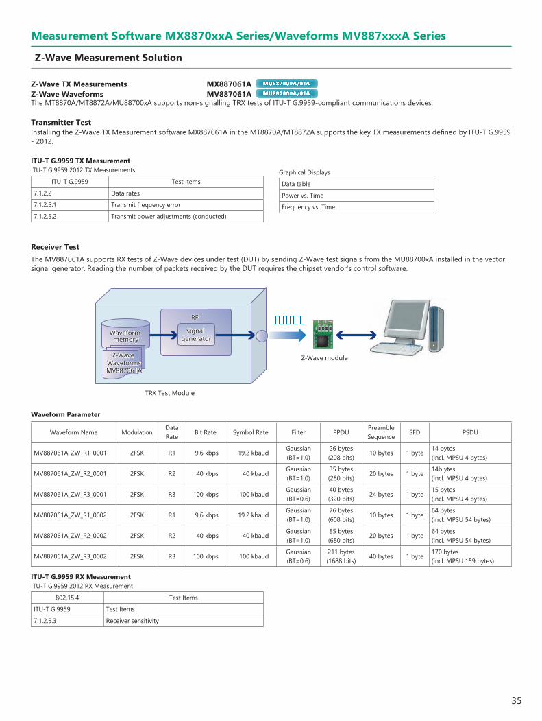
Z-Wave TX Measurements MX887061A MU887000A/01A Z-Wave Waveforms MV887061A MU887000A/01A
The MT8870A/MT8872A/MU88700xA supports non-signalling TRX tests of ITU-T G.9959-compliant communications devices.
Transmitter TestInstalling the Z-Wave TX Measurement software MX887061A in the MT8870A/MT8872A supports the key TX measurements defined by ITU-T G.9959 - 2012.
ITU-T G.9959 TX MeasurementITU-T G.9959 2012 TX Measurements
ITU-T G.9959 Test Items
7.1.2.2 Data rates
7.1.2.5.1 Transmit frequency error
7.1.2.5.2 Transmit power adjustments (conducted)
Graphical Displays
Data table
Power vs. Time
Frequency vs. Time
Measurement Software MX8870xxA Series/Waveforms MV887xxxA Series
Z-Wave Measurement Solution
Receiver TestThe MV887061A supports RX tests of Z-Wave devices under test (DUT) by sending Z-Wave test signals from the MU88700xA installed in the vector signal generator. Reading the number of packets received by the DUT requires the chipset vendor's control software.
Z-Wave moduleZ-Wave WaveformsMV887061A
RFRF
Z-Wave WaveformsMV887061A
Waveform memory
Signal generator
Waveform memory
Signal generator
TRX Test Module
Waveform Parameter
Waveform Name ModulationData Rate
Bit Rate Symbol Rate Filter PPDUPreamble Sequence
SFD PSDU
MV887061A_ZW_R1_0001 2FSK R1 9.6 kbps 19.2 kbaudGaussian(BT=1.0)
26 bytes(208 bits)
10 bytes 1 byte14 bytes(incl. MPSU 4 bytes)
MV887061A_ZW_R2_0001 2FSK R2 40 kbps 40 kbaudGaussian(BT=1.0)
35 bytes(280 bits)
20 bytes 1 byte14b ytes(incl. MPSU 4 bytes)
MV887061A_ZW_R3_0001 2FSK R3 100 kbps 100 kbaudGaussian(BT=0.6)
40 bytes(320 bits)
24 bytes 1 byte15 bytes(incl. MPSU 4 bytes)
MV887061A_ZW_R1_0002 2FSK R1 9.6 kbps 19.2 kbaudGaussian(BT=1.0)
76 bytes(608 bits)
10 bytes 1 byte64 bytes(incl. MPSU 54 bytes)
MV887061A_ZW_R2_0002 2FSK R2 40 kbps 40 kbaudGaussian(BT=1.0)
85 bytes(680 bits)
20 bytes 1 byte64 bytes(incl. MPSU 54 bytes)
MV887061A_ZW_R3_0002 2FSK R3 100 kbps 100 kbaudGaussian(BT=0.6)
211 bytes(1688 bits)
40 bytes 1 byte170 bytes(incl. MPSU 159 bytes)
ITU-T G.9959 RX MeasurementITU-T G.9959 2012 RX Measurement
802.15.4 Test Items
ITU-T G.9959 Test Items
7.1.2.5.3 Receiver sensitivity

36
MV8871xxA Series WaveformsThe MT8870A/MT8872A/MU88700xA supports RX tests of receivers using the various common communications technologies in widespread use today.
RX Test Using WaveformsThe Waveforms MV8871xxA series is a file of waveforms for generating any output waveform standardized by each communications technology. Saving and selecting these files in the internal waveform memory of the MU88700xA makes it easy to output a signal for any waveform pattern from the built-in vector signal generator. Waveform file generated from the MU88700xA vector signal generator can be used to run sensitivity tests and simple BER RX tests* on GPS and digital broadcast equipment supporting mobile terminals and communications appliances.
*: An external attenuator is required when running RX tests at lower levels than the lower output limit of the signal generator.
ReceiverWaveformsMV8871xxA Series
RFRF
WaveformsMV8871xxA Series
Waveform memory
Signal generator
Waveform memory
Signal generator
TRX Test Module
Measurement Software MX8870xxA Series/Waveforms MV887xxxA Series
Receiver Measurement Solution

37
Measurement Software MX8870xxA Series/Waveforms MV887xxxA Series
Main Specifications of MV8871xxA Series Waveforms
GPS Waveforms MV887100A MU887000A/01A/02A
Waveform File Name MV887100A_GPS_0002 MV887100A_GPS_0003
Application Sensitivity test/BER measurement Parity detection/Sensitivity test
Transmitted Data Modulation Method BPSK
Satellite ID Number 1
Reference Standard GLOBAL POSITIONING SYSTEM STANDARD POSITIONING SERVICE SIGNAL SPECIFICATION
GPS L5 Waveforms MV887100A-002 MU887000A/01A/02A
Waveform File Name MV887100A_GPS_0040
Application Sensitivity test
Transmitted Data Modulation Method BPSK
Satellite ID Number 1
Reference Standard GLOBAL POSITIONING SYSTEM STANDARD POSITIONING SERVICE SIGNAL SPECIFICATION
*: MV887100A GPS waveforms license is required.
Galileo Waveforms MV887101A MU887000A/01A/02A
Waveform File Name MV887101A_GALILEO_0001
Application Parity detection/Sensitivity test
Transmitted Data Modulation Method QPSK or CBOC (depending on selecting waveforms)
Satellite ID Number 1
Reference Standard European GNSS (Galileo) Open Service Signal In Space Interface Control Document
GLONASS Waveforms MV887102A MU887000A/01A/02A
Waveform File Name MV887102A_GLONASS_0001MV887102A_GLONASS_010xMV887102A_GLONASS_011x
Application Sensitivity test/BER measurementSimultaneous GPS and GLONASS measurements*1, C/No measurements
Transmitted Data Modulation Method BPSK BPSK
Satellite ID Number 3 –
Reference Standard INTERFACE CONTROL DOCUMENT Navigational radio signal In bands L1, L2 Edition 5.1
*1: MV887100A GPS waveforms license is required to perform simultaneous GPS and GLONASS measurements.
BeiDou Waveform MV887103A MU887000A/01A/02A
Waveform File Name MV887103A_BEIDOU_0002
Application Parity detection/Sensitivity test
Transmitted Data Modulation Method QPSK (Only I phase)
Satellite ID Number 1, 6 (depending on selected waveforms)
Reference Standard BeiDou Navigation Satellite System Signal In Space Interface Control Document Open Service Signal (Version 2.0)
QZSS Waveforms MV887104A MU887000A/01A
Waveform File Name MV887104A_QZSS_0001
Application Parity detection/Sensitivity test/BER measurement
Transmitted Data Modulation Method BPSK
Satellite ID Number 193
Reference Standard Quasi-Zenith Satellite System Interface Specification
DVB-H Waveforms MV887110A MU887000A/01A/02A
Waveform File Name MV887110A_DVBH_0001
Application Simple BER measurement
Transmitted Data PN9fix*2
Transmitted Data Modulation Method QPSK
Encoding Rate 2/3
System Bandwidth 8 MHz
CelI ID 0x0000
Reference Standard ETSI EN 300 744 V1.5.1 (2004-11)
*2: fix indicates the PN sequence is not continued if the waveform is regenerated from the first position.

38
Measurement Software MX8870xxA Series/Waveforms MV887xxxA Series
Main Specifications of MV8871xxA Series Waveforms
ISDB-T Waveforms MV887111A MU887000A/01A/02A
Waveform File Name MV887111A_ISDBT_0001 MV887111A_ISDBT_0002 MV887111A_ISDBT_0003 MV887111A_ISDBT_0004
Application Device evaluation Video and audio evaluation*3 Simple BER measurement
Waveform Cycle/Group 2 [Frame] 40 [Frame] 40 [Frame] 4 [Frame]
Transmitted Data PN23fix*4
Transmitted Data Modulation Method
Layer A: 64QAMandLayer A: QPSKLayer B: 64QAM
Layer A: QPSKLayer B: 64QAM
Layer A: QPSK or 16QAMLayer B: 64QAM
Guard Interval 1/8
Encoding Rate No EncodingLayer A: 2/3Layer B: 7/8
Layer A: 2/3Layer B: 3/4
Layer A: 2/3 or 1/2Layer B: 3/4 or 7/8
Mode 3
Reference Standard ARIB STD-B31
*3: RX not guaranteed for all receivers*4: fix indicates the PN sequence is not continued if the waveform is regenerated from the first position.
ISDB-Tmm Waveforms MV887112A MU887000A/01A
Waveform File Name
MV887112A_ISDBTmm_SSpatA_000x_0M (x = 1 to 6)MV887112A_ISDBTmm_SSpatA_000x_8M (x = 1 to 6)MV887112A_ISDBTmm_SSpatC_000x_0M (x = 7 to 12)MV887112A_ISDBTmm_SSpatC_000x_8M (x = 7 to 12)The XXXX_8M waveform pattern is a waveform with the file name XXXX_0M to which an 8-MHz offset has been added.
Application Simple BER measurement
Waveform Cycle/Group 4 [Frame]
Transmitted Data PN23fix*5
Transmitted Data Modulation Method QPSK or 16QAM
Waveform Format A type or C type
Guard Interval 1/4
Encoding Rate 1/2 or 2/3
Mode 3
Reference Standard ARIB STD-B46
*5: fix indicates the PN sequence is not continued if the waveform is regenerated from the first position.
Consult Anritsu for details about each waveforms.
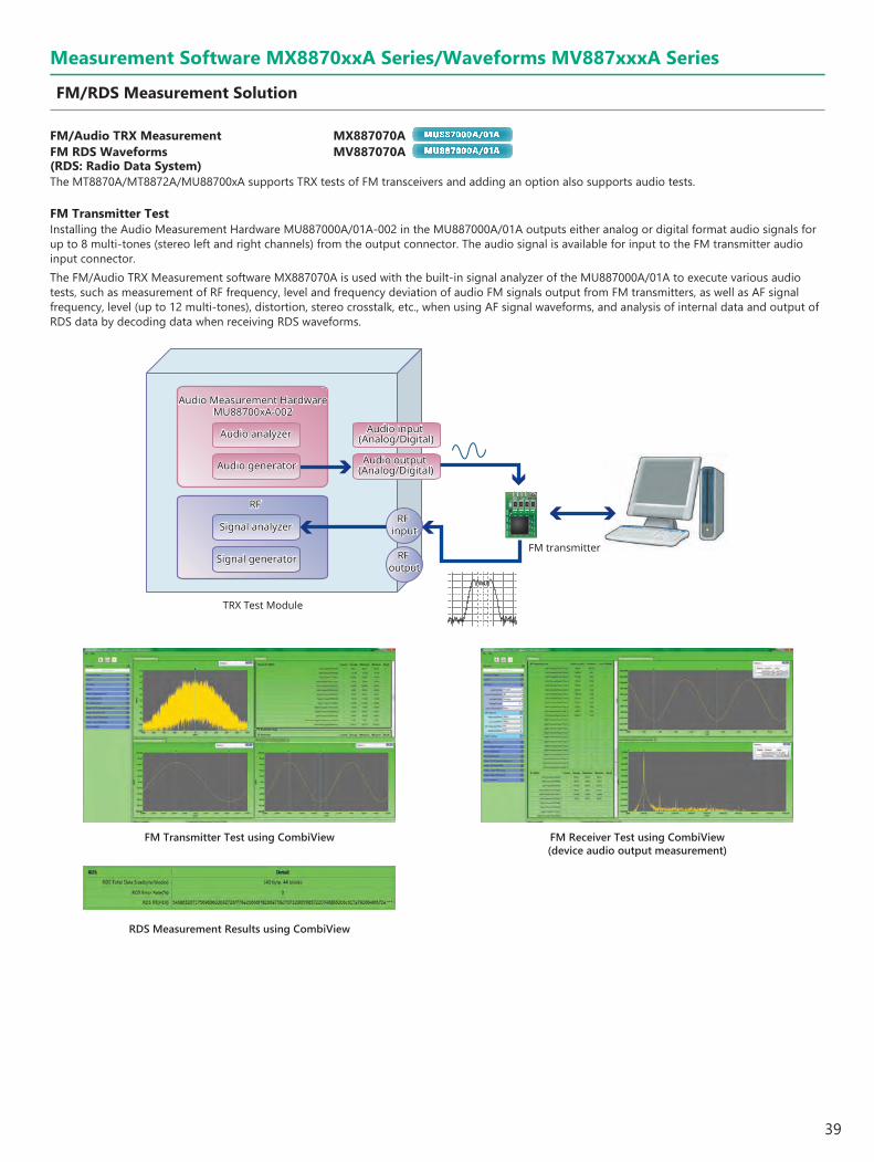
39
FM/Audio TRX Measurement MX887070A MU887000A/01A FM RDS Waveforms MV887070A MU887000A/01A (RDS: Radio Data System)The MT8870A/MT8872A/MU88700xA supports TRX tests of FM transceivers and adding an option also supports audio tests.
FM Transmitter TestInstalling the Audio Measurement Hardware MU887000A/01A-002 in the MU887000A/01A outputs either analog or digital format audio signals for up to 8 multi-tones (stereo left and right channels) from the output connector. The audio signal is available for input to the FM transmitter audio input connector.The FM/Audio TRX Measurement software MX887070A is used with the built-in signal analyzer of the MU887000A/01A to execute various audio tests, such as measurement of RF frequency, level and frequency deviation of audio FM signals output from FM transmitters, as well as AF signal frequency, level (up to 12 multi-tones), distortion, stereo crosstalk, etc., when using AF signal waveforms, and analysis of internal data and output of RDS data by decoding data when receiving RDS waveforms.
TRX Test Module
Signal generator
Signal analyzer
RF
Audio generator
Audio analyzer
Audio Measurement HardwareMU88700xA-002
RF output
RF input
Audio output (Analog/Digital)
Audio input (Analog/Digital)
Signal generator
Signal analyzer
RF
Audio generator
Audio analyzer
Audio Measurement HardwareMU88700xA-002
FM transmitterRF
output
RF input
Audio output (Analog/Digital)
Audio input (Analog/Digital)
FM Transmitter Test using CombiView
RDS Measurement Results using CombiView
Measurement Software MX8870xxA Series/Waveforms MV887xxxA Series
FM/RDS Measurement Solution
FM Receiver Test using CombiView (device audio output measurement)

40
Measurement Software MX8870xxA Series/Waveforms MV887xxxA Series
FM/RDS Measurement Solution (continued)
FM Receiver TestTo test FM receivers using the FM/Audio TRX Measurement software MX887070A, the specified test audio signal is frequency modulated and a signal is output from the vector signal generator. Installing the Audio Measurement Hardware MU887000A/01A-002 in the MU887000A/01A inputs either analog or digital format audio signals output from the FM receiver to the built-in audio analyzer of the MU887000A/01A to perform audio tests including AF signal frequency and level (up to 12 multi-tones), distortion rate, stereo crosstalk, etc.
FM receiver
Audio Measurement HardwareMU88700xA-002
Audio Measurement HardwareMU88700xA-002
RFRF
Signal generator
Signal analyzer
Audio generator
Audio analyzer
RF output
RF input
Audio output (Analog/Digital)
Audio input (Analog/Digital)
Signal generator
Signal analyzer
Audio generator
Audio analyzer
RF output
RF input
Audio output (Analog/Digital)
Audio input (Analog/Digital)
TRX Test Module
Main Specifications of FM RDS WaveformsWaveform File Name MV887070A_FMRDS_0001 MV887070A_FMRDS_0002 MV887070A_FMRDS_0003 MV887070A_FMRDS_0004
Application DUT RDS RX function test DUT RX test
AF LeftChannel
Tone Count 1
Tone Frequency 1 kHz
Tone Deviation 75 kHz × 0.9
AF RightChannel
Tone Count 1
Tone Frequency 2 kHz
Tone Deviation 75 kHz × 0.9
Pilot Deviation 75 kHz × 0.1
RDS Deviation 75 kHz × 0.05
Reference Standard IEC 62106 Edition 2.0
Consult Anritsu for details about the FM RDS waveform file.
FM Receiver Test RDS (Radio Data System)Loading the FM RDS Waveforms MV887070A supports output of waveforms including transmitted data such as radio text data from the built-in vector signal generator based on the FM RDS (Radio Data System) standard.
RFRF
RDS waveform
RDS waveform
FM receiver
Audio Measurement HardwareMU88700xA-002
Audio Measurement HardwareMU88700xA-002
Signal generator
Signal analyzer
Audio generator
Audio analyzer
RF output
RF input
Audio output (Analog/Digital)
Audio input (Analog/Digital)
Signal generator
Signal analyzer
Audio generator
Audio analyzer
RF output
RF input
Audio output (Analog/Digital)
Audio input (Analog/Digital)
TRX Test Module
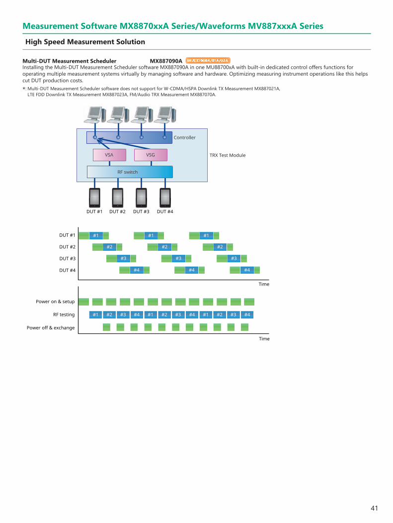
41
Multi-DUT Measurement Scheduler MX887090A MU887000A/01A/02A
Installing the Multi-DUT Measurement Scheduler software MX887090A in one MU88700xA with built-in dedicated control offers functions for operating multiple measurement systems virtually by managing software and hardware. Optimizing measuring instrument operations like this helps cut DUT production costs.
*: Multi-DUT Measurement Scheduler software does not support for W-CDMA/HSPA Downlink TX Measurement MX887021A, LTE FDD Downlink TX Measurement MX887023A, FM/Audio TRX Measurement MX887070A.
#1 #1 #1
#2 #2 #2
#3 #3 #3
#4 #4 #4
#1 #2 #3 #4 #1 #2 #3 #4 #1 #2 #3 #4
DUT #1
Time
DUT #2
DUT #3
DUT #4
RF testing
Power off & exchange
Power on & setup
Time
Controller
VSA VSG
RF switch
TRX Test Module
DUT #1 DUT #2 DUT #3 DUT #4
Measurement Software MX8870xxA Series/Waveforms MV887xxxA Series
High Speed Measurement Solution

42
f : frequencyp: level/power
Electrical CharacteristicsNumber of Slots 4
Internal Reference Oscillator
Starting characteristics25°C, Referenced to frequency at 24-hour after power-on
±5 × 10⁻⁷ (2 minutes after power-on)±5 × 10⁻⁸ (5 minutes after power-on)
Aging rate: ±1 × 10⁻⁷/yearTemperature characteristics: ±2 × 10⁻⁸ (+5°C to +45°C)Initial calibration accuracy
+20°C to +30°C, 1 hour after power-on±2.2 × 10⁻⁸
Connector
External reference inputConnector: BNC-J (rear panel), 50Ω (nom.)Frequency: 10 MHzOperating range: ±1 ppmInput level: –15 to +20 dBm, 50Ω (AC coupling)
Reference signal output Connector: BNC-J (rear panel), 50Ω (nom.)Frequency: 10 MHzOutput level: ≥0 dBm (AC coupling)
TriggerInput/Output switching: Trigger input/output selectableConnector: BNC-J (rear panel, 4 ports) Input/Output level: TTL level
Ethernet controllerControl from external controller (excluding power-on/off)
Ethernet (1000BASE-T)Connector: RJ-45 (front panel, rear panel)
GPIB (with MT8870A-001)Connector: IEEE488 bus connector (rear panel, 4 ports)
AUXConnector: 50-pin (correspond to DX10BM-50S, rear panel)
General
Dimensions and Mass426 (W) × 221.5 (H) × 498 (D) mm (excluding projections)≤11.5 kg (excluding all options and test modules)≤30.0 kg (including options and test modules)
Power SupplyPower voltage: 100 VAC to 120 VAC/200 VAC to 240 VACFrequency: 50 Hz/60 HzPower consumption: ≤900 VA (including all options and test modules)
Temperature Range +5°C to +45°C (operating), –20°C to +60°C (storage)
CE
EMC 2014/30/EU, EN61326-1, EN61000-3-2
LVD 2014/35/EU, EN61010-1
RoHS 2011/65/EU, (EU) 2015/863, EN IEC 63000: 2018
Universal Wireless Test Set MT8870A Specifications
43
Electrical Characteristics
Number of Slots 2
Internal Reference Oscillator
Starting characteristics25°C, Referenced to frequency at 24-hour after power-on
±5 × 10⁻⁷ (2 minutes after power-on)±5 × 10⁻⁸ (5 minutes after power-on)
Aging rate: ±1 × 10⁻⁷/yearTemperature characteristics: ±2 × 10⁻⁸ (5°C to 45°C)
Connector
External Reference InputConnector: BNC-J (Rear panel), 50Ω (nominal)Frequency: 10 MHzOperating range: ±1 ppmInput level: –15 to +20 dBm, 50Ω (AC coupling)
Reference Signal Output Connector: BNC-J (Rear panel), 50Ω (nominal)Frequency: 10 MHzOutput level: ≥0 dBm (AC coupling)
TriggerInput/Output switching: Trigger Input/Output selectableConnector: BNC-J (Rear panel: 2 ports) Input/Output level: TTL level
Ethernet ControllerControl from external controller (Excluding power-On/Off)
Ethernet (1000BASE-T)Connector: RJ-45 (Front panel, Rear panel)
GPIB (With MT8872A-001)Connector: IEEE488 bus connector (Rear panel: 2 ports)
AuxConnector: 50-pin (Correspond to DX10BM-50S, Rear panel)
General
Dimensions and Mass250 (W) × 221.5 (H) × 498 (D) mm (Exclusive of surface projections)≤9.5 kg (Excluding all options and modules)<18.0 kg (Including options and modules)
Power SupplyPower voltage: 100 VAC to 120 VAC/200 VAC to 240 VACFrequency: 50 Hz/60 HzPower consumption: ≤500 VA (Including all options and modules)
Temperature Range +5°C to +45°C (Operating), –20°C to +60°C (Storage)
EMC EN61326-1, EN61000-3-2
Universal Wireless Test Set MT8872A Specifications
44
Input/Output Connector
RF Test Ports
Number of ports4
Connector N (female)
Impedance50Ω (nom.)
VSWR Test port 1 and 2
<1.5 (10 MHz ≤ f < 400 MHz)<1.2 (400 MHz ≤ f ≤ 2.7 GHz)<1.3 (2.7 GHz < f ≤ 3.8 GHz)<1.5 (3.8 GHz < f ≤ 6.0 GHz)
Test port 3 and 4<1.8 (10 MHz ≤ f < 30 MHz)<1.5 (30 MHz ≤ f ≤ 3.8 GHz)<1.6 (3.8 GHz < f ≤ 6.0 GHz)
Maximum input level+35 dBm (Test port 1 and 2)+25 dBm (Test port 3 and 4)
AF Test Ports
PortsAnalog port, Digital port
ConnectorAnalog port: BNC (female)Digital port: RJ-45
Signal Generator
Frequency
Setting range10 MHz to 3.8 GHz 10 MHz to 6.0 GHz (with MU887000A-001)
Setting Resolution1 Hz
Accuracy Depends on MT8870A reference oscillator accuracy
Amplitude
Setting rangeTest port 1 and 2
–130 to –10 dBm (≤3.8 GHz) –130 to –18 dBm (>3.8 GHz)
Test port 3 and 4–120 to 0 dBm (≤3.8 GHz) –120 to –8 dBm (>3.8 GHz)
Setting Resolution0.1 dB
AccuracyCW, After CAL, 10°C to 40°CTest port 1 and 2
Output level: ≥–120 dBm (≤3.8 GHz), ≥–100 dBm (>3.8 GHz)±1.3 dB (10 MHz ≤ f < 400 MHz) (Signal Analyzer input level: +15 dBm) ±1.0 dB, ±0.7 dB (typ.) (400 MHz ≤ f ≤ 3.8 GHz) ±1.3 dB, ±1.0 dB (typ.) (3.8 GHz < f ≤ 6.0 GHz)
Test port 3 and 4Output level: ≥ –110 dBm
±1.3 dB (10 MHz ≤ f < 400 MHz) ±1.0 dB, ±0.7 dB (typ.) (400 MHz ≤ f ≤ 3.8 GHz) ±1.3 dB, ±0.7 dB (typ.) (3.8 GHz < f ≤ 6.0 GHz)
Spurious Response Harmonic distortion<–25 dBc
Vector Modulation Bandwidth160 MHz (max.)
Signal Analyzer
Frequency
Setting range10 MHz to 3.8 GHz 10 MHz to 6.0 GHz (with MU887000A-001)
Setting resolution1 Hz
Measurement resolution0.1 Hz
TRX Test Module MU887000A Specifications
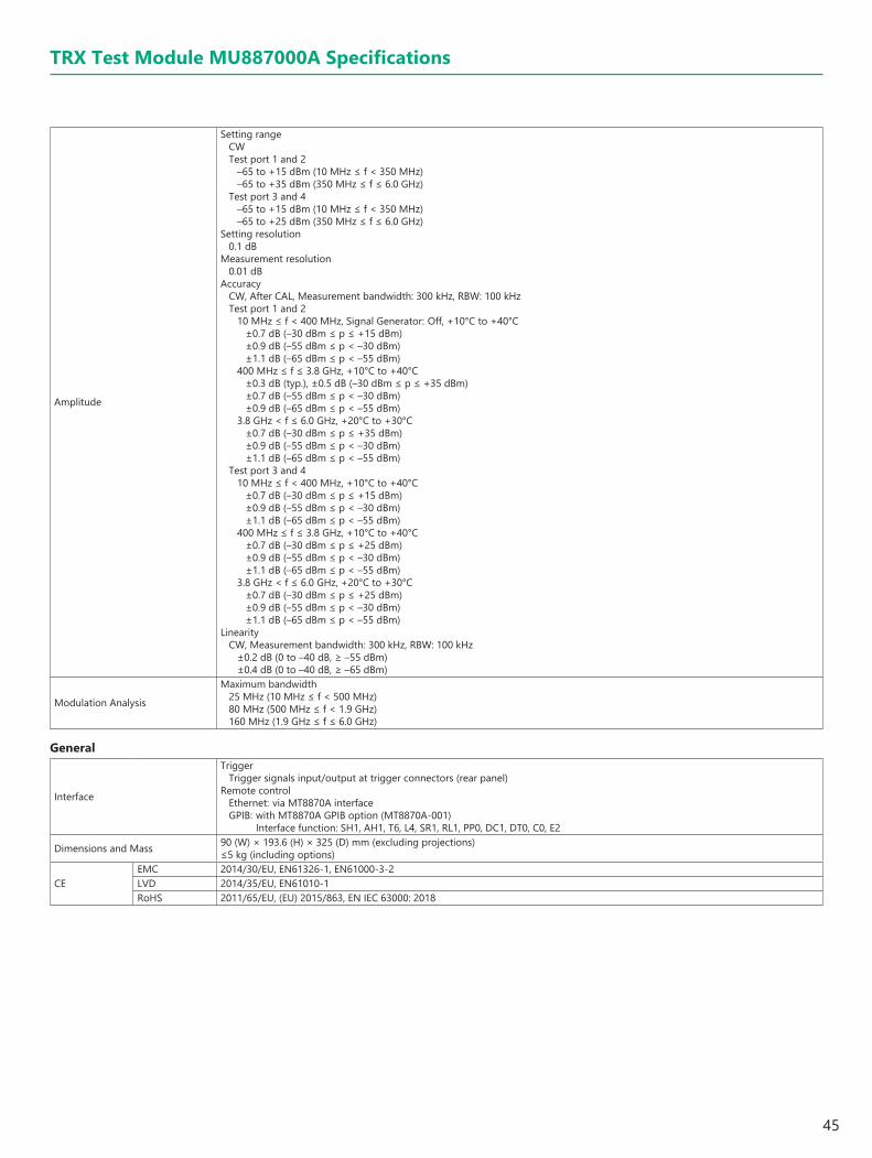
45
TRX Test Module MU887000A Specifications
Amplitude
Setting rangeCWTest port 1 and 2
–65 to +15 dBm (10 MHz ≤ f < 350 MHz)–65 to +35 dBm (350 MHz ≤ f ≤ 6.0 GHz)
Test port 3 and 4–65 to +15 dBm (10 MHz ≤ f < 350 MHz)–65 to +25 dBm (350 MHz ≤ f ≤ 6.0 GHz)
Setting resolution0.1 dB
Measurement resolution0.01 dB
AccuracyCW, After CAL, Measurement bandwidth: 300 kHz, RBW: 100 kHz Test port 1 and 2
10 MHz ≤ f < 400 MHz, Signal Generator: Off, +10°C to +40°C±0.7 dB (–30 dBm ≤ p ≤ +15 dBm) ±0.9 dB (–55 dBm ≤ p < –30 dBm) ±1.1 dB (–65 dBm ≤ p < –55 dBm)
400 MHz ≤ f ≤ 3.8 GHz, +10°C to +40°C±0.3 dB (typ.), ±0.5 dB (–30 dBm ≤ p ≤ +35 dBm)±0.7 dB (–55 dBm ≤ p < –30 dBm)±0.9 dB (–65 dBm ≤ p < –55 dBm)
3.8 GHz < f ≤ 6.0 GHz, +20°C to +30°C±0.7 dB (–30 dBm ≤ p ≤ +35 dBm)±0.9 dB (–55 dBm ≤ p < –30 dBm)±1.1 dB (–65 dBm ≤ p < –55 dBm)
Test port 3 and 410 MHz ≤ f < 400 MHz, +10°C to +40°C
±0.7 dB (–30 dBm ≤ p ≤ +15 dBm)±0.9 dB (–55 dBm ≤ p < –30 dBm)±1.1 dB (–65 dBm ≤ p < –55 dBm)
400 MHz ≤ f ≤ 3.8 GHz, +10°C to +40°C±0.7 dB (–30 dBm ≤ p ≤ +25 dBm)±0.9 dB (–55 dBm ≤ p < –30 dBm)±1.1 dB (–65 dBm ≤ p < –55 dBm)
3.8 GHz < f ≤ 6.0 GHz, +20°C to +30°C±0.7 dB (–30 dBm ≤ p ≤ +25 dBm)±0.9 dB (–55 dBm ≤ p < –30 dBm)±1.1 dB (–65 dBm ≤ p < –55 dBm)
LinearityCW, Measurement bandwidth: 300 kHz, RBW: 100 kHz
±0.2 dB (0 to –40 dB, ≥ –55 dBm)±0.4 dB (0 to –40 dB, ≥ –65 dBm)
Modulation Analysis
Maximum bandwidth25 MHz (10 MHz ≤ f < 500 MHz)80 MHz (500 MHz ≤ f < 1.9 GHz)160 MHz (1.9 GHz ≤ f ≤ 6.0 GHz)
General
Interface
TriggerTrigger signals input/output at trigger connectors (rear panel)
Remote control Ethernet: via MT8870A interface GPIB: with MT8870A GPIB option (MT8870A-001)
Interface function: SH1, AH1, T6, L4, SR1, RL1, PP0, DC1, DT0, C0, E2
Dimensions and Mass 90 (W) × 193.6 (H) × 325 (D) mm (excluding projections)≤5 kg (including options)
CEEMC 2014/30/EU, EN61326-1, EN61000-3-2LVD 2014/35/EU, EN61010-1RoHS 2011/65/EU, (EU) 2015/863, EN IEC 63000: 2018

46
Audio Measurement Hardware MU887000A-002
Analog Audio
Audio generatorFrequency range: 20 Hz to 20 kHzOutput level range: 0 (off), 1 mV to 5 Vpeak (100 kΩ termination)Impedance: 1Ω (AC coupling) (nom.)
Audio analyzerFrequency range: 20 Hz to 20 kHzInput level range: 1 mVpeak to 5 Vpeak (30 V rms max.)Impedance: 100 kΩ (AC coupling)
Digital Audio
Audio generatorFrequency range: 20 Hz to 20 kHz (Sampling rate: 44.1 kHz, 48 kHz)
20 Hz to 14 kHz (Sampling rate: 32 kHz) 20 Hz to 7 kHz (Sampling rate: 16 kHz)
Bit resolution: 16 bits/24 bitsAudio analyzer
Sampling rate: 16, 32, 44.1, 48 kHzBit resolution: 16 bits/24 bits
Input/Output Connector
RF Test Ports
Number of ports4
Connector N (female)
Impedance50Ω (nom.)
VSWR <1.5 (10 MHz ≤ f < 400 MHz)<1.2 (400 MHz ≤ f ≤ 2.7 GHz)<1.3 (2.7 GHz < f ≤ 3.8 GHz)<1.5 (3.8 GHz < f ≤ 6.0 GHz)
Maximum input level+35 dBm
AF Test Ports
PortsAnalog port, Digital port
ConnectorAnalog port: BNC (female)Digital port: RJ-45
Signal Generator
Frequency
Setting range10 MHz to 3.8 GHz 10 MHz to 6.0 GHz (with MU887001A-001)
Setting Resolution1 Hz
Accuracy Depends on MT8870A reference oscillator accuracy
Amplitude
Setting range–130 to –10 dBm (≤3.8 GHz) –130 to –18 dBm (>3.8 GHz)
Setting Resolution0.1 dB
AccuracyCW, After CAL, 10°C to 40°COutput level: ≥–120 dBm (≤3.8 GHz), ≥–100 dBm (>3.8 GHz)
±1.3 dB (10 MHz ≤ f < 400 MHz) (Signal Analyzer input level: +15 dBm) ±1.0 dB, ±0.7 dB (typ.) (400 MHz ≤ f ≤ 3.8 GHz) ±1.3 dB, ±1.0 dB (typ.) (3.8 GHz < f ≤ 6.0 GHz)
Spurious Response Harmonic distortion
<–25 dBc
Vector ModulationBandwidth
160 MHz (max.)
TRX Test Module MU887001A Specifications

47
Signal Analyzer
Frequency
Setting range10 MHz to 3.8 GHz 10 MHz to 6.0 GHz (with MU887001A-001)
Setting resolution1 Hz
Measurement resolution0.1 Hz
Amplitude
Setting rangeCW–65 to +15 dBm (10 MHz ≤ f < 350 MHz)–65 to +35 dBm (350 MHz ≤ f ≤ 6.0 GHz)
Setting resolution0.1 dB
Measurement resolution0.01 dB
AccuracyCW, After CAL, Measurement bandwidth: 300 kHz, RBW: 100 kHz 10 MHz ≤ f < 400 MHz, Signal Generator: Off, +10°C to +40°C
±0.7 dB (–30 dBm ≤ p ≤ +15 dBm) ±0.9 dB (–55 dBm ≤ p < –30 dBm) ±1.1 dB (–65 dBm ≤ p < –55 dBm)
400 MHz ≤ f ≤ 3.8 GHz, +10°C to +40°C±0.3 dB (typ.), ±0.5 dB (–30 dBm ≤ p ≤ +35 dBm)±0.7 dB (–55 dBm ≤ p < –30 dBm)±0.9 dB (–65 dBm ≤ p < –55 dBm)
3.8 GHz < f ≤ 6.0 GHz, +20°C to +30°C±0.7 dB (–30 dBm ≤ p ≤ +35 dBm)±0.9 dB (–55 dBm ≤ p < –30 dBm)±1.1 dB (–65 dBm ≤ p < –55 dBm)
LinearityCW, Measurement bandwidth: 300 kHz, RBW: 100 kHz
±0.2 dB (0 to –40 dB, ≥ –55 dBm)±0.4 dB (0 to –40 dB, ≥ –65 dBm)
Modulation Analysis
Maximum bandwidth25 MHz (10 MHz ≤ f < 500 MHz)80 MHz (500 MHz ≤ f < 1.9 GHz)160 MHz (1.9 GHz ≤ f ≤ 6.0 GHz)
General
Interface
TriggerTrigger signals input/output at trigger connectors (rear panel)
Remote control Ethernet: via MT8870A interface GPIB: with MT8870A GPIB option (MT8870A-001)
Interface function: SH1, AH1, T6, L4, SR1, RL1, PP0, DC1, DT0, C0, E2
Dimensions and Mass 90 (W) × 193.6 (H) × 325 (D) mm (excluding projections) ≤5 kg (including options)
CE
EMC 2014/30/EU, EN61326-1, EN61000-3-2
LVD 2014/35/EU, EN61010-1
RoHS 2011/65/EU, (EU) 2015/863, EN IEC 63000: 2018
Audio Measurement Hardware MU887001A-002
Analog Audio
Audio generatorFrequency range: 20 Hz to 20 kHzOutput level range: 0 (off), 1 mV to 5 Vpeak (100 kΩ termination)Impedance: 1Ω (AC coupling) (nom.)
Audio analyzerFrequency range: 20 Hz to 20 kHzInput level range: 1 mVpeak to 5 Vpeak (30 V rms max.)Impedance: 100 kΩ (AC coupling)
Digital Audio
Audio generatorFrequency range: 20 Hz to 20 kHz (Sampling rate: 44.1 kHz, 48 kHz)
20 Hz to 14 kHz (Sampling rate: 32 kHz) 20 Hz to 7 kHz (Sampling rate: 16 kHz)
Bit resolution: 16 bits/24 bitsAudio analyzer
Sampling rate: 16, 32, 44.1, 48 kHzBit resolution: 16 bits/24 bits
TRX Test Module MU887001A Specifications
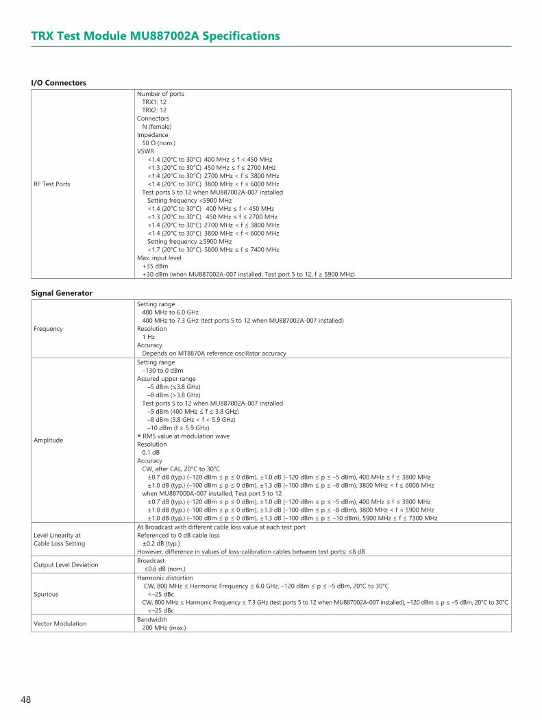
48
TRX Test Module MU887002A Specifications
I/O Connectors
RF Test Ports
Number of portsTRX1: 12TRX2: 12
ConnectorsN (female)
Impedance50 Ω (nom.)
VSWR <1.4 (20°C to 30°C) 400 MHz ≤ f < 450 MHz<1.3 (20°C to 30°C) 450 MHz ≤ f ≤ 2700 MHz<1.4 (20°C to 30°C) 2700 MHz < f ≤ 3800 MHz<1.4 (20°C to 30°C) 3800 MHz < f ≤ 6000 MHz
Test ports 5 to 12 when MU887002A-007 installedSetting frequency <5900 MHz<1.4 (20°C to 30°C) 400 MHz ≤ f < 450 MHz<1.3 (20°C to 30°C) 450 MHz ≤ f ≤ 2700 MHz<1.4 (20°C to 30°C) 2700 MHz < f ≤ 3800 MHz<1.4 (20°C to 30°C) 3800 MHz < f < 6000 MHzSetting frequency ≥5900 MHz<1.7 (20°C to 30°C) 5800 MHz ≤ f ≤ 7400 MHz
Max. input level+35 dBm+30 dBm (when MU887002A-007 installed, Test port 5 to 12, f ≥ 5900 MHz)
Signal Generator
Frequency
Setting range400 MHz to 6.0 GHz400 MHz to 7.3 GHz (test ports 5 to 12 when MU887002A-007 installed)
Resolution1 Hz
AccuracyDepends on MT8870A reference oscillator accuracy
Amplitude
Setting range–130 to 0 dBm
Assured upper range–5 dBm (≤3.8 GHz)–8 dBm (>3.8 GHz)
Test ports 5 to 12 when MU887002A-007 installed–5 dBm (400 MHz ≤ f ≤ 3.8 GHz)–8 dBm (3.8 GHz < f < 5.9 GHz)–10 dBm (f ≥ 5.9 GHz)
* RMS value at modulation waveResolution
0.1 dBAccuracy
CW, after CAL, 20°C to 30°C±0.7 dB (typ.) (–120 dBm ≤ p ≤ 0 dBm), ±1.0 dB (–120 dBm ≤ p ≤ –5 dBm), 400 MHz ≤ f ≤ 3800 MHz±1.0 dB (typ.) (–100 dBm ≤ p ≤ 0 dBm), ±1.3 dB (–100 dBm ≤ p ≤ –8 dBm), 3800 MHz < f ≤ 6000 MHz
when MU887000A-007 installed, Test port 5 to 12±0.7 dB (typ.) (–120 dBm ≤ p ≤ 0 dBm), ±1.0 dB (–120 dBm ≤ p ≤ –5 dBm), 400 MHz ≤ f ≤ 3800 MHz ±1.0 dB (typ.) (–100 dBm ≤ p ≤ 0 dBm), ±1.3 dB (–100 dBm ≤ p ≤ –8 dBm), 3800 MHz < f < 5900 MHz ±1.0 dB (typ.) (–100 dBm ≤ p ≤ 0 dBm), ±1.3 dB (–100 dBm ≤ p ≤ –10 dBm), 5900 MHz ≤ f ≤ 7300 MHz
Level Linearity at Cable Loss Setting
At Broadcast with different cable loss value at each test portReferenced to 0 dB cable loss
±0.2 dB (typ.)However, difference in values of loss-calibration cables between test ports: ≤8 dB
Output Level Deviation Broadcast ≤0.6 dB (nom.)
Spurious
Harmonic distortion CW, 800 MHz ≤ Harmonic Frequency ≤ 6.0 GHz, –120 dBm ≤ p ≤ –5 dBm, 20°C to 30°C
<–25 dBcCW, 800 MHz ≤ Harmonic Frequency ≤ 7.3 GHz (test ports 5 to 12 when MU887002A-007 installed), –120 dBm ≤ p ≤ –5 dBm, 20°C to 30°C
<–25 dBc
Vector Modulation Bandwidth200 MHz (max.)
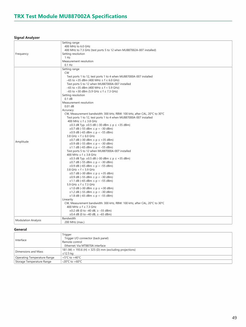
49
TRX Test Module MU887002A Specifications
Signal Analyzer
Frequency
Setting range400 MHz to 6.0 GHz400 MHz to 7.3 GHz (test ports 5 to 12 when MU887002A-007 installed)
Setting resolution1 Hz
Measurement resolution0.1 Hz
Amplitude
Setting rangeCW
Test ports 1 to 12, test ports 1 to 4 when MU887000A-007 installed–65 to +35 dBm (400 MHz ≤ f ≤ 6.0 GHz)Test ports 5 to 12 when MU887000A-007 installed–65 to +35 dBm (400 MHz ≤ f < 5.9 GHz)–65 to +30 dBm (5.9 GHz ≤ f ≤ 7.3 GHz)
Setting resolution0.1 dB
Measurement resolution0.01 dB
AccuracyCW, Measurement bandwidth: 300 kHz, RBW: 100 kHz, after CAL, 20°C to 30°C
Test ports 1 to 12, test ports 1 to 4 when MU887000A-007 installed 400 MHz ≤ f ≤ 3.8 GHz
±0.3 dB Typ. ±0.5 dB (–30 dBm ≤ p ≤ +35 dBm)±0.7 dB (–55 dBm ≤ p < –30 dBm)±0.9 dB (–65 dBm ≤ p < –55 dBm)
3.8 GHz < f ≤ 6.0 GHz±0.7 dB (–30 dBm ≤ p ≤ +35 dBm)±0.9 dB (–55 dBm ≤ p < –30 dBm)±1.1 dB (–65 dBm ≤ p < –55 dBm)
Test ports 5 to 12 when MU887000A-007 installed400 MHz ≤ f ≤ 3.8 GHz
±0.3 dB Typ. ±0.5 dB (–30 dBm ≤ p ≤ +35 dBm)±0.7 dB (–55 dBm ≤ p < –30 dBm)±0.9 dB (–65 dBm ≤ p < –55 dBm)
3.8 GHz < f < 5.9 GHz±0.7 dB (–30 dBm ≤ p ≤ +35 dBm)±0.9 dB (–55 dBm ≤ p < –30 dBm)±1.1 dB (–65 dBm ≤ p < –55 dBm)
5.9 GHz ≤ f ≤ 7.3 GHz±1.0 dB (–30 dBm ≤ p ≤ +30 dBm)±1.2 dB (–55 dBm ≤ p < –30 dBm)±1.8 dB (–65 dBm ≤ p < –55 dBm)
LinearityCW, Measurement bandwidth: 300 kHz, RBW: 100 kHz, after CAL, 20°C to 30°C
400 MHz ≤ f ≤ 7.3 GHz±0.2 dB (0 to –40 dB, ≥ –55 dBm)±0.4 dB (0 to –40 dB, ≥ –65 dBm)
Modulation Analysis Bandwidth200 MHz (max.)
General
Interface
TriggerTrigger I/O connector (back panel)
Remote controlEthernet: Via MT8870A interface
Dimensions and Mass 181 (W) × 193.6 (H) × 325 (D) mm (excluding projections)≤12.5 kg
Operating Temperature Range +5°C to +40°CStorage Temperature Range –20°C to +60°C

50
Measurement Software MX8870xxA Series/Waveforms MV887xxxA Series Specifications
Cellular Standards Sequence Measurement MX887010A
Common Item
Measuring objectLTE-Advanced/NR sub-6 GHz
Frequency range400 MHz to 6.0 GHz
Spectrum Monitor
Analysis time1 ms, 10 ms
Span1, 2.5, 5, 10, 25, 50, 100, 160, 200* MHz
RBWSpan RBW1 MHz 100 Hz, 300 Hz, 1 kHz, 3 kHz, 10 kHz
2.5 MHz 1 kHz, 3 kHz, 10 kHz, 30 kHz5 MHz 3 kHz, 10 kHz, 30 kHz, 100 kHz
10 MHz 3 kHz, 10 kHz, 30 kHz, 100 kHz25 MHz 10 kHz, 30 kHz, 100 kHz, 300 kHz50 MHz 30 kHz, 100 kHz, 300 kHz, 1 MHz
100 MHz 30 kHz, 100 kHz, 300 kHz, 1 MHz160 MHz 30 kHz, 100 kHz, 300 kHz, 1 MHz
200 MHz* 30 kHz, 100 kHz, 300 kHz, 1 MHzDetection mode
Average, PeakPower measurement bandwidth
Range: 0.001 MHz to (setting span) MHz, Resolution: 0.001 MHz
Multiple Power Measurement
Number of steps10 to 100 steps
Power step time0.5, 1,2, 4, 5, 10, 20, 30, 40, 50, 60, 70, 80 ms
Filter typeLow-pass filter: 1.23, 1.4, 3, 5, 10, 15, 20 MHzRRC filter: 3.84 MHz
Measurement windowRange: 1 to 90%, Resolution 1%
Trigger level–40 to 0 dB (based on the input level)
TX/RX vs. Frequency
Segment durationRange: 1 to 80 ms, Resolution: 1 ms
Measurement filterLow-pass filter: 1.23, 1.4, 3, 5, 10, 15, 20 MHzRRC filter: 3.84 MHz
Measurement windowRange: 1 to 90%, Resolution: 1%
Number of segment1 to 1600
Number of sequence1 to 400
Narrowband Power vs. Time
Segment durationRange: 200 µs to 20000 µs, Resolution: 1 µs
Measurement bandwidth15 kHz
Measurement windowRange: 1 to 90%, Resolution: 1%
Number of segment1 to 1000
IQ Capturing
Time spanRange: 1000 μs to 10000 μs, Resolution : 1 μs
Measurement bandwidthLow-pass filter: 100, 300, 500 kHz, 1, 3, 5, 20 MHzGaussian filter: 1 MHz
*: MU887002A only
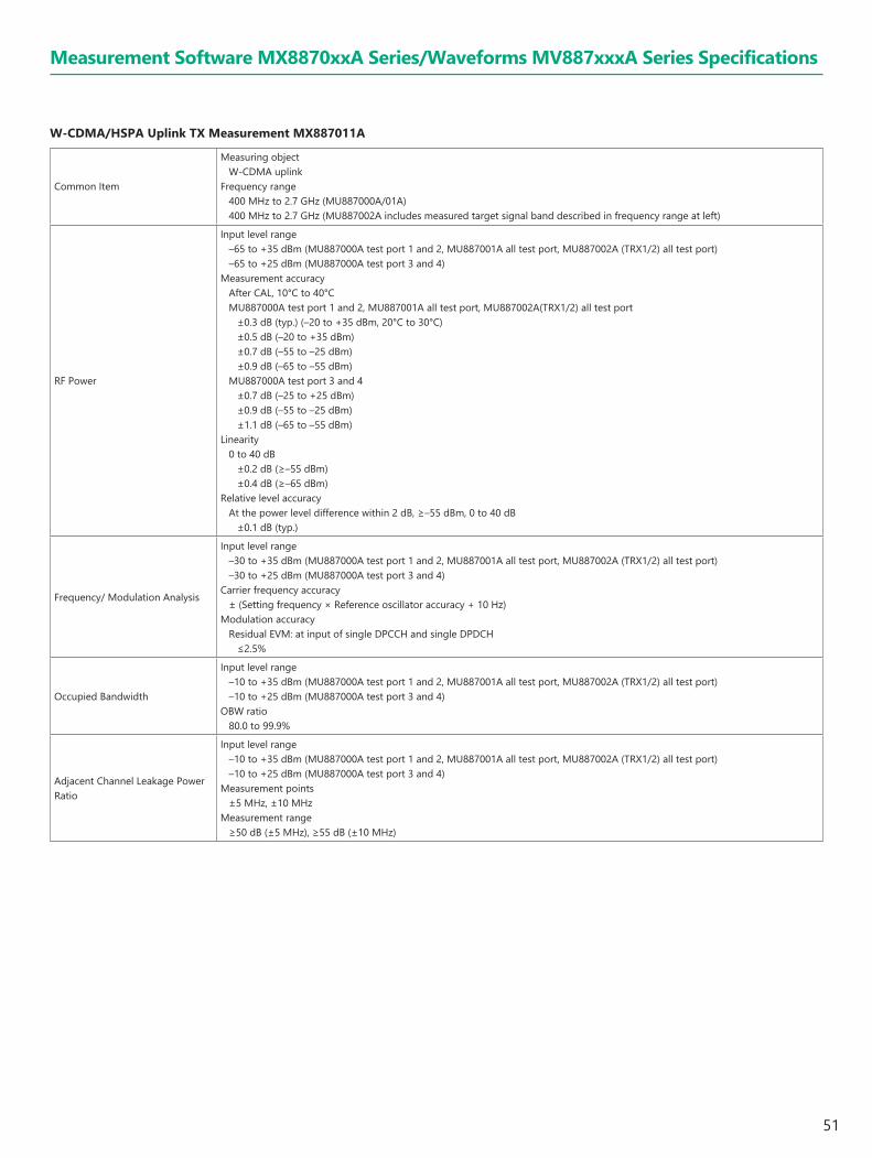
51
Measurement Software MX8870xxA Series/Waveforms MV887xxxA Series Specifications
W-CDMA/HSPA Uplink TX Measurement MX887011A
Common Item
Measuring objectW-CDMA uplink
Frequency range400 MHz to 2.7 GHz (MU887000A/01A)400 MHz to 2.7 GHz (MU887002A includes measured target signal band described in frequency range at left)
RF Power
Input level range–65 to +35 dBm (MU887000A test port 1 and 2, MU887001A all test port, MU887002A (TRX1/2) all test port)–65 to +25 dBm (MU887000A test port 3 and 4)
Measurement accuracyAfter CAL, 10°C to 40°CMU887000A test port 1 and 2, MU887001A all test port, MU887002A(TRX1/2) all test port
±0.3 dB (typ.) (–20 to +35 dBm, 20°C to 30°C)±0.5 dB (–20 to +35 dBm)±0.7 dB (–55 to –25 dBm)±0.9 dB (–65 to –55 dBm)
MU887000A test port 3 and 4±0.7 dB (–25 to +25 dBm)±0.9 dB (–55 to –25 dBm)±1.1 dB (–65 to –55 dBm)
Linearity0 to 40 dB
±0.2 dB (≥–55 dBm)±0.4 dB (≥–65 dBm)
Relative level accuracyAt the power level difference within 2 dB, ≥–55 dBm, 0 to 40 dB
±0.1 dB (typ.)
Frequency/ Modulation Analysis
Input level range–30 to +35 dBm (MU887000A test port 1 and 2, MU887001A all test port, MU887002A (TRX1/2) all test port)–30 to +25 dBm (MU887000A test port 3 and 4)
Carrier frequency accuracy± (Setting frequency × Reference oscillator accuracy + 10 Hz)
Modulation accuracyResidual EVM: at input of single DPCCH and single DPDCH
≤2.5%
Occupied Bandwidth
Input level range–10 to +35 dBm (MU887000A test port 1 and 2, MU887001A all test port, MU887002A (TRX1/2) all test port)–10 to +25 dBm (MU887000A test port 3 and 4)
OBW ratio80.0 to 99.9%
Adjacent Channel Leakage Power Ratio
Input level range–10 to +35 dBm (MU887000A test port 1 and 2, MU887001A all test port, MU887002A (TRX1/2) all test port)–10 to +25 dBm (MU887000A test port 3 and 4)
Measurement points±5 MHz, ±10 MHz
Measurement range≥50 dB (±5 MHz), ≥55 dB (±10 MHz)
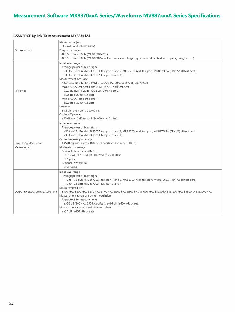
52
GSM/EDGE Uplink TX Measurement MX887012A
Common Item
Measuring objectNormal burst (GMSK, 8PSK)
Frequency range400 MHz to 2.0 GHz (MU887000A/01A)400 MHz to 2.0 GHz (MU887002A includes measured target signal band described in frequency range at left)
RF Power
Input level rangeAverage power of burst signal
–30 to +35 dBm (MU887000A test port 1 and 2, MU887001A all test port, MU887002A (TRX1/2) all test port)–30 to +25 dBm (MU887000A test port 3 and 4)
Measurement accuracyAfter CAL, 10°C to 40°C (MU887000A/01A), 20°C to 30°C (MU887002A)MU887000A test port 1 and 2, MU887001A all test port
±0.3 dB (typ.) (–20 to +35 dBm, 20°C to 30°C)±0.5 dB (–20 to +35 dBm)
MU887000A test port 3 and 4±0.7 dB (–30 to +25 dBm)
Linearity±0.2 dB (≥–30 dBm, 0 to 40 dB)
Carrier off power≥65 dB (≥–10 dBm), ≥45 dB (–30 to –10 dBm)
Frequency/Modulation Measurement
Input level rangeAverage power of burst signal
–30 to +35 dBm (MU887000A test port 1 and 2, MU887001A all test port, MU887002A (TRX1/2) all test port)–30 to +25 dBm (MU887000A test port 3 and 4)
Carrier frequency accuracy± (Setting frequency × Reference oscillator accuracy + 10 Hz)
Modulation accuracyResidual phase error (GMSK)
≤0.5°rms (f ≥500 MHz), ≤0.7°rms (f <500 MHz)≤2° peak
Residual EVM (8PSK)≤1.5% rms
Output RF Spectrum Measurement
Input level rangeAverage power of burst signal
–10 to +35 dBm (MU887000A test port 1 and 2, MU887001A all test port, MU887002A (TRX1/2) all test port)–10 to +25 dBm (MU887000A test port 3 and 4)
Measurement point±100 kHz, ±200 kHz, ±250 kHz, ±400 kHz, ±600 kHz, ±800 kHz, ±1000 kHz, ±1200 kHz, ±1600 kHz, ±1800 kHz, ±2000 kHz
Measurement range of due to modulationAverage of 10 measurements
≤–55 dB (200 kHz, 250 kHz offset), ≤–66 dB (≥400 kHz offset)Measurement range of switching transient
≤–57 dB (≥400 kHz offset)
Measurement Software MX8870xxA Series/Waveforms MV887xxxA Series Specifications

53
LTE FDD Uplink TX Measurement MX887013A LTE TDD Uplink TX Measurement MX887014A
Common Item
Measuring objectPUSCH, PUCCH
Frequency range600 MHz to 2.7 GHz, 3.4 GHz to 3.8 GHz (MU887000A/01A)600 MHz to 2.7 GHz, 3.4 GHz to 4.2 GHz (with MU887000A/01A-001/101 option)600 MHz to 2.7 GHz, 3.4 GHz to 4.2 GHz (MU887002A)
RF Power
Input level range–65 to +35 dBm (MU887000A test port 1 and 2, MU887001A all test port, MU887002A (TRX1/2) all test port)–65 to +25 dBm (MU887000A test port 3 and 4)
Measurement accuracy600 MHz to 2.7 GHz, 3.4 GHz to 3.8 GHz, After CAL, 10°C to 40°C (MU887000A/01A), 20°C to 30°C (MU887002A)MU887000A test port 1 and 2, MU887001A all test ports, MU887002A (TRX1/2) all test port
±0.3 dB (typ.) (–20 to +35 dBm, 20°C to 30°C)±0.5 dB (–20 to +35 dBm)±0.7 dB (–50 to –20 dBm)±0.9 dB (–60 to –50 dBm)
MU887000A test port 3 and 4±0.7 dB (–20 to +25 dBm)±0.9 dB (–50 to –20 dBm)±1.1 dB (–60 to –50 dBm)
3.8 GHz to 4.2 GHz, After CAL, 20°C to 30°CMU887000A all test ports and MU887001A all test ports, MU887002A (TRX1/2) all test port
±0.7 dB (–20 to +35 dBm) ±0.9 dB (–50 to –20 dBm) ±1.1 dB (–60 to –50 dBm)
Linearity0 to 40 dB
±0.2 dB (≥–50 dBm)±0.4 dB (≥–60 dBm)
Relative level accuracyAt the power level difference within 2 dB
±0.1 dB (typ.)
Frequency/Modulation Measurement
Input level range–40 to +35 dBm (MU887000A test port 1 and 2, MU887001A all test port, MU887002A (TRX1/2) all test port)–40 to +25 dBm (MU887000A test port 3 and 4)
Carrier frequency accuracy± (Setting frequency × Reference oscillator accuracy + 15 Hz)
Modulation accuracyResidual EVM (average of 20 measurements)
≤2.5%In-band emission
Input level: ≥–10 dBm, Allocated RB: ≤18≤–40 dBc
Occupied Bandwidth
Input level range–10 to +35 dBm (MU887000A test port 1 and 2, MU887001A all test port, MU887002A (TRX1/2) all test port)–10 to +25 dBm (MU887000A test port 3 and 4)
OBW ratio80.0 to 99.9%
Adjacent Channel Leakage Power Ratio
Input level range–10 to +35 dBm (MU887000A test port 1 and 2, MU887001A all test port)–10 to +25 dBm (MU887000A test port 3 and 4)–10 to +35 dBm (MU887002A (TRX1/2) all test port, 600 MHz ≤ f ≤ 2700 MHz)–14 to +35 dBm (MU887002A (TRX1/2) all test port, 3400 MHz ≤ f ≤ 4200 MHz)
Measurement range≥45 dB (E-UTRA ACLR1), ≥50 dB (UTRA ACLR1), ≥55 dB (UTRA ACLR2)
Spectrum Emission MaskInput level range
–10 to +35 dBm (MU887000A test port 1 and 2, MU887001A all test port, MU887002A (TRX1/2) all test port)–10 to +25 dBm (MU887000A test port 3 and 4)
Measurement Software MX8870xxA Series/Waveforms MV887xxxA Series Specifications

54
Measurement Software MX8870xxA Series/Waveforms MV887xxxA Series Specifications
LTE-Advanced FDD Uplink CA TX Measurement MX887013A-001 LTE-Advanced TDD Uplink CA TX Measurement MX887014A-001
Common Item
Measuring objectPUSCH
Frequency range698 MHz to 2.7 GHz, 3.4 GHz to 3.8 GHz698 MHz to 2.7 GHz, 3.4 GHz to 4.2 GHz (with MU88700xA-001/101 option)698 MHz to 2.7 GHz, 3.4 GHz to 4.2 GHz (with MU887002A)
RF Power
Input level range–65 to +35 dBm (MU887000A test port 1 and 2, MU887001A all test ports, MU887002A (TRX1/2) all test port)–65 to +25 dBm (MU887000A test port 3 and 4)
Measurement accuracyMU887000A test port 1 and 2, MU887001A all test ports, MU887002A (TRX1/2) all test portExcluding when measuring Intraband Contiguous CA SCC and PCC + SCC 698 MHz to 2.7 GHz, 3.4 GHz to 3.8 GHz , After CAL, 10°C to 40°C (MU887000A/01A), 20°C to 30°C (MU887002A)
±0.3 dB (typ.) (–20 to +35 dBm, 20°C to 30°C)±0.5 dB (–20 to +35 dBm)±0.7 dB (–50 to –20 dBm)±0.9 dB (–60 to –50 dBm)
3.8 GHz to 4.2 GHz, After CAL, 10°C to 40°C±0.7 dB (–20 to +35 dBm)±0.9 dB (–50 to –20 dBm)±1.1 dB (–60 to –50 dBm)
MU887000A test port 1 and 2, MU887001A all test ports, MU887002A (TRX1/2) all test portWhen measuring Intraband Contiguous CA SCC and PCC + SCC698 MHz to 2.7 GHz, After CAL, 10°C to 40°C (MU887000A/01A), 20°C to 30°C (MU887002A)
±0.5 dB (typ.) (–20 to +35 dBm, 20°C to 30°C)±0.7 dB (–50 to +35 dBm)±0.9 dB (–60 to –50 dBm)
3.4 GHz to 3.8 GHz, After CAL, 10°C to 40°C3.8 GHz to 4.2 GHz, After CAL, 20°C to 30°C
±1.0 dB (–50 to +35 dBm)±1.3 dB (–60 to –50 dBm)
MU887000A test port 3 and 4Excluding when measuring Intraband Contiguous CA SCC and PCC + SCC698 MHz to 2.7 GHz, 3.4 GHz to 3.8 GHz , After CAL, 10°C to 40°C3.8 GHz to 4.2 GHz , After CAL, 20°C to 30°C
±0.7 dB (–20 to +25 dBm)±0.9 dB (–50 to –20 dBm)±1.1 dB (–60 to –50 dBm)
MU887000A test port 3 and 4When measuring Intraband Contiguous CA SCC and PCC + SCC698 MHz to 2.7 GHz, After CAL, 10°C to 40°C
±0.7 dB (–20 to +25 dBm)±0.9 dB (–50 to –20 dBm)±1.1 dB (–60 to –50 dBm)
3.4 GHz to 3.8 GHz, After CAL, 10°C to 40°C3.8 GHz to 4.2 GHz, After CAL, 20°C to 30°C
±1.0 dB (–50 to +25 dBm)±1.3 dB (–60 to –50 dBm)
Linearity0 to 30 dB, 20 to 30°C
±0.2 dB (≥–50 dBm)±0.4 dB (≥–60 dBm)
Frequency/Modulation Measurement
Input level range–40 to +35 dBm (MU887000A test port 1 and 2, MU887001A all test ports, MU887002A (TRX1/2) all test port)–40 to +25 dBm (MU887000A test port 3 and 4)
Carrier frequency accuracy± (Setting frequency × Reference oscillator accuracy + 15 Hz)
Modulation accuracyResidual EVM (average of 20 measurements)
≤2.5%In-band emission
Input level: ≥–10 dBm, Allocated RB: ≤18≤–40 dBc
Occupied Bandwidth
Input level range–10 to +35 dBm (MU887000A test port 1 and 2, MU887001A all test ports, MU887002A (TRX1/2) all test port)–10 to +25 dBm (MU887000A test port 3 and 4)
OBW ratio80.0 to 99.9%
Adjacent Channel Leakage Power Ratio
Input level range–10 to +35 dBm (MU887000A test port 1 and 2, MU887001A all test port)–10 to +25 dBm (MU887000A test port 3 and 4)–10 to +35 dBm (MU887002A (TRX1/2) all test port, 698 MHz ≤ f ≤ 2700 MHz)–14 to +35 dBm (MU887002A (TRX1/2) all test port, 3400 MHz ≤ f ≤ 4200 MHz)
Measurement range≥45 dB (E-UTRA ACLR1), ≥50 dB (UTRA ACLR1), ≥55 dB (UTRA ACLR2)
Spectrum Emission MaskInput level range
–10 to +35 dBm (MU887000A test port 1 and 2, MU887001A all test ports, MU887002A (TRX1/2) all test port)–10 to +25 dBm (MU887000A test port 3 and 4)

55
CDMA2000 Reverse Link TX Measurement MX887015A
Common Item
Measuring objectReverse RC-1/2/3/4
Frequency range400 MHz to 2.7 GHz (MU887000A/01A)400 MHz to 2.7 GHz (MU887002A includes measured target signal band described in frequency range at left)
RF Power
Input level range–65 to +35 dBm (MU887000A test port 1 and 2, MU887001A all test port, MU887002A (TRX1/2) all test port)–65 to +25 dBm (MU887000A test port 3 and 4)
Measurement accuracyAfter CAL, 10°C to 40°C (MU887000A/01A), 20°C to 30°C (MU887002A)MU887000A test port 1 and 2, MU887001A all test port, MU887002A (TRX1/2) all test port
±0.3 dB (typ.) (–20 to +35 dBm, 20°C to 30°C)±0.5 dB (–20 to +35 dBm)±0.7 dB (–55 to –25 dBm)±0.9 dB (–65 to –55 dBm)
MU887000A test port 3 and 4±0.7 dB (–25 to +25 dBm)±0.9 dB (–55 to –25 dBm)±1.1 dB (–65 to –55 dBm)
Linearity0 to 40 dB
±0.2 dB (≥–55 dBm)±0.4 dB (≥–65 dBm)
Frequency/Modulation Measurement
Input level range–30 to +35 dBm (MU887000A test port 1 and 2, MU887001A all test port, MU887002A (TRX1/2) all test port)–30 to +25 dBm (MU887000A test port 3 and 4)
Carrier frequency accuracy± (Setting frequency × Reference oscillator accuracy + 10 Hz)
Waveform quality>0.999
Code Domain Power Measurement
Reverse RC3 or RC4Input level range
–30 to +35 dBm (MU887000A test port 1 and 2, MU887001A all test port, MU887002A (TRX1/2) all test port)–30 to +25 dBm (MU887000A test port 3 and 4)
Measurement accuracy±0.2 dB (Code power: ≥–15 dBc), ±0.4 dB (Code power: ≥–23 dBc)
Occupied Bandwidth
Input level range–10 to +35 dBm (MU887000A test port 1 and 2, MU887001A all test port, MU887002A (TRX1/2) all test port)–10 to +25 dBm (MU887000A test port 3 and 4)
OBW ratio80.0 to 99.9%
Measurement Software MX8870xxA Series/Waveforms MV887xxxA Series Specifications

56
1xEV-DO Reverse Link TX Measurement MX887016A
Common Item
Measuring objectReverse link Rev. 0/Rev. A
Frequency range400 MHz to 2.7 GHz (MU887000A/01A)400 MHz to 2.7 GHz (MU887002A includes measured target signal band described in frequency range at left)
RF Power
Input level range–65 to +35 dBm (MU887000A test port 1 and 2, MU887001A all test port, MU887002A (TRX1/2) all test port)–65 to +25 dBm (MU887000A test port 3 and 4)
Measurement accuracyAfter CAL, 10°C to 40°C (MU887000A/01A), 20°C to 30°C (MU887002A)MU887000A test port 1 and 2, MU887001A all test port, MU887002A (TRX1/2) all test port
±0.3 dB (typ.) (–20 to +35 dBm, 20°C to 30°C)±0.5 dB (–20 to +35 dBm)±0.7 dB (–55 to –25 dBm)±0.9 dB (–65 to –55 dBm)
MU887000A test port 3 and 4±0.7 dB (–25 to +25 dBm)±0.9 dB (–55 to –25 dBm)±1.1 dB (–65 to –55 dBm)
Linearity0 to 40 dB
±0.2 dB (≥–55 dBm)±0.4 dB (≥–65 dBm)
Frequency/Modulation Measurement
Input level range–30 to +35 dBm (MU887000A test port 1 and 2, MU887001A all test port, MU887002A (TRX1/2) all test port)–30 to +25 dBm (MU887000A test port 3 and 4)
Carrier frequency accuracy± (Setting frequency × Reference oscillator accuracy + 10 Hz)
Waveform quality>0.999
Code Domain Power Measurement
Input level range–30 to +35 dBm (MU887000A test port 1 and 2, MU887001A all test port, MU887002A (TRX1/2) all test port)–30 to +25 dBm (MU887000A test port 3 and 4)
Measurement accuracy±0.2 dB (Code power: ≥–15 dBc), ±0.4 dB (Code power: ≥–23 dBc)
Occupied Bandwidth
Input level range–10 to +35 dBm (MU887000A test port 1 and 2, MU887001A all test port, MU887002A (TRX1/2) all test port)–10 to +25 dBm (MU887000A test port 3 and 4)
OBW ratio80.0 to 99.9%
Measurement Software MX8870xxA Series/Waveforms MV887xxxA Series Specifications

57
TD-SCDMA Uplink TX Measurement MX887017A
Common Item
Measuring objectTD-SCDMA uplink
Frequency range400 MHz to 2.7 GHz (MU887000A/01A)400 MHz to 2.7 GHz (MU887002A includes measured target signal band described in frequency range at left)
RF Power
Input level range–65 to +35 dBm (MU887000A test port 1 and 2, MU887001A all test port, MU887002A (TRX1/2) all test port)–65 to +25 dBm (MU887000A test port 3 and 4)
Measurement accuracyAfter CAL, 10°C to 40°C (MU887000A/01A), 20°C to 30°C (MU887002A)MU887000A test port 1 and 2, MU887001A all test port, MU887002A (TRX1/2) all test port
±0.3 dB (typ.) (–20 to +35 dBm, 20°C to 30°C)±0.5 dB (–20 to +35 dBm)±0.7 dB (–55 to –25 dBm)±0.9 dB (–65 to –55 dBm)
MU887000A test port 3 and 4±0.7 dB (–25 to +25 dBm)±0.9 dB (–55 to –25 dBm)±1.1 dB (–65 to –55 dBm)
Linearity0 to 40 dB
±0.2 dB (≥–55 dBm)±0.4 dB (≥–65 dBm)
Frequency/Modulation Measurement
Input level range–30 to +35 dBm (MU887000A test port 1 and 2, MU887001A all test port, MU887002A (TRX1/2) all test port)–30 to +25 dBm (MU887000A test port 3 and 4)
Carrier frequency accuracy± (Setting frequency × Reference oscillator accuracy + 10 Hz)
Modulation accuracyResidual EVM (at input of single code)
≤2.5%
Occupied Bandwidth
Input level range–10 to +35 dBm (MU887000A test port 1 and 2, MU887001A all test port, MU887002A (TRX1/2) all test port)–10 to +25 dBm (MU887000A test port 3 and 4)
OBW ratio99.0%
Adjacent Channel Leakage Power Ratio
Input level range–10 to +35 dBm (MU887000A test port 1 and 2, MU887001A all test port, MU887002A (TRX1/2) all test port)–10 to +25 dBm (MU887000A test port 3 and 4)
Measurement points±1.6 MHz, ±3.2 MHz
Measurement range≥50 dB (±1.6 MHz), ≥55 dB (±3.2 MHz)
Measurement Software MX8870xxA Series/Waveforms MV887xxxA Series Specifications
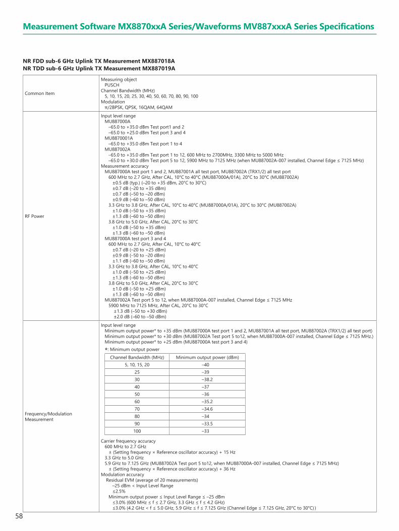
58
NR FDD sub-6 GHz Uplink TX Measurement MX887018A NR TDD sub-6 GHz Uplink TX Measurement MX887019A
Common Item
Measuring objectPUSCH
Channel Bandwidth (MHz)5, 10, 15, 20, 25, 30, 40, 50, 60, 70, 80, 90, 100
Modulationπ/2BPSK, QPSK, 16QAM, 64QAM
RF Power
Input level rangeMU887000A
–65.0 to +35.0 dBm Test port1 and 2–65.0 to +25.0 dBm Test port 3 and 4
MU8870001A –65.0 to +35.0 dBm Test port 1 to 4
MU887002A–65.0 to +35.0 dBm Test port 1 to 12, 600 MHz to 2700MHz, 3300 MHz to 5000 MHz–65.0 to +30.0 dBm Test port 5 to 12, 5900 MHz to 7125 MHz (when MU887002A-007 installed, Channel Edge ≤ 7125 MHz)
Measurement accuracyMU887000A test port 1 and 2, MU887001A all test port, MU887002A (TRX1/2) all test port
600 MHz to 2.7 GHz, After CAL, 10°C to 40°C (MU887000A/01A), 20°C to 30°C (MU887002A)±0.5 dB (typ.) (–20 to +35 dBm, 20°C to 30°C)±0.7 dB (–20 to +35 dBm)±0.7 dB (–50 to –20 dBm)±0.9 dB (–60 to –50 dBm)
3.3 GHz to 3.8 GHz, After CAL, 10°C to 40°C (MU887000A/01A), 20°C to 30°C (MU887002A)±1.0 dB (–50 to +35 dBm)±1.3 dB (–60 to –50 dBm)
3.8 GHz to 5.0 GHz, After CAL, 20°C to 30°C±1.0 dB (–50 to +35 dBm)±1.3 dB (–60 to –50 dBm)
MU887000A test port 3 and 4600 MHz to 2.7 GHz, After CAL, 10°C to 40°C
±0.7 dB (–20 to +25 dBm)±0.9 dB (–50 to –20 dBm)±1.1 dB (–60 to –50 dBm)
3.3 GHz to 3.8 GHz, After CAL, 10°C to 40°C±1.0 dB (–50 to +25 dBm)±1.3 dB (–60 to –50 dBm)
3.8 GHz to 5.0 GHz, After CAL, 20°C to 30°C±1.0 dB (–50 to +25 dBm)±1.3 dB (–60 to –50 dBm)
MU887002A Test port 5 to 12, when MU887000A-007 installed, Channel Edge ≤ 7125 MHz5900 MHz to 7125 MHz, After CAL, 20°C to 30°C
±1.3 dB (–50 to +30 dBm) ±2.0 dB (–60 to –50 dBm)
Frequency/Modulation Measurement
Input level rangeMinimum output power* to +35 dBm (MU887000A test port 1 and 2, MU887001A all test port, MU887002A (TRX1/2) all test port)Minimum output power* to +30 dBm (MU887002A Test port 5 to12, when MU887000A-007 installed, Channel Edge ≤ 7125 MHz.)Minimum output power* to +25 dBm (MU887000A test port 3 and 4)
*: Minimum output powerChannel Bandwidth (MHz) Minimum output power (dBm)
5, 10, 15, 20 –4025 –3930 –38.240 –3750 –3660 –35.270 –34.680 –3490 –33.5100 –33
Carrier frequency accuracy600 MHz to 2.7 GHz
± (Setting frequency × Reference oscillator accuracy) + 15 Hz3.3 GHz to 5.0 GHz5.9 GHz to 7.125 GHz (MU887002A Test port 5 to12, when MU887000A-007 installed, Channel Edge ≤ 7125 MHz)
± (Setting frequency × Reference oscillator accuracy) + 36 HzModulation accuracy
Residual EVM (average of 20 measurements)–25 dBm < Input Level Range≤2.5%
Minimum output power ≤ Input Level Range ≤ –25 dBm≤3.0% (600 MHz ≤ f ≤ 2.7 GHz, 3.3 GHz ≤ f ≤ 4.2 GHz)≤3.0% (4.2 GHz < f ≤ 5.0 GHz, 5.9 GHz ≤ f ≤ 7.125 GHz (Channel Edge ≤ 7.125 GHz, 20°C to 30°C) )
Measurement Software MX8870xxA Series/Waveforms MV887xxxA Series Specifications

59
Measurement Software MX8870xxA Series/Waveforms MV887xxxA Series Specifications
Occupied Bandwidth
Frequency rangeChannel Bandwidth ≤ 60 MHz
600 MHz to 2.7 GHz, 3.3 GHz to 3.8 GHz (MU887000A/01A)600 MHz to 2.7 GHz, 3.3 GHz to 5.0 GHz (MU887000A/01A-001/101 option)600 MHz to 2.7 GHz, 3.3 GHz to 5.0 GHz (MU887002A)5.9 GHz to 7.125 GHz (when MU887002A-007 installed, Channel Edge ≤ 7125 MHz, Test port 5 to 12)
60 MHz < Channel Bandwidth 2.0 GHz to 2.7 GHz, 3.3 GHz to 3.8 GHz (MU887000A/01A)2.0 GHz to 2.7 GHz, 3.3 GHz to 5.0 GHz (MU887000A/01A-001/101 option)2.0 GHz to 2.7 GHz, 3.3 GHz to 5.0 GHz (MU887002A)5.9 GHz to 7.125 GHz (when MU887002A-007 installed, Channel Edge ≤ 7125 MHz, Test port 5 to 12)
Input level range–10 to +35 dBm (MU887000A test port 1 and 2, MU887001A all test port, MU887002A (TRX1/2) all test port)–10 to +30 dBm (MU887002A test port 5 to 12, when MU887000A-007 installed, Channel Edge ≤ 7125 MHz, Test port 5 to 12)–10 to +25 dBm (MU887000A test port 3 and 4)
Adjacent Channel Leakage Power Ratio
Frequency rangeChannel Bandwidth ≤ 60 MHz
600 MHz to 2.7 GHz, 3.3 GHz to 3.8 GHz (MU887000A/01A)600 MHz to 2.7 GHz, 3.3 GHz to 5.0 GHz (MU887000A/01A-001/101 option)600 MHz to 2.7 GHz, 3.3 GHz to 5.0 GHz (MU887002A)5.9 GHz to 7.125 GHz (when MU887002A-007 installed, Channel Edge ≤ 7125 MHz, Test port 5 to 12)
60 MHz < Channel Bandwidth 2.0 GHz to 2.7 GHz, 3.3 GHz to 3.8 GHz (MU887000A/01A)2.0 GHz to 2.7 GHz, 3.3 GHz to 5.0 GHz (MU887000A/01A-001/101 option)2.0 GHz to 2.7 GHz, 3.3 GHz to 5.0 GHz (MU887002A)5.9 GHz to 7.125 GHz (when MU887002A-007 installed, Channel Edge ≤ 7125 MHz, Test port 5 to 12)
Input level range–10 to +35 dBm (MU887000A test port 1 and 2, MU887001A all test port, MU887002A (TRX1/2) all test port)–10 to +30 dBm (when MU887002A-007 installed, (TRX1/2) test port 5 to 12, 5900 MHz to 7125 MHz, Channel Edge ≤ 7125 MHz)–10 to +25 dBm (MU887000A test por 3, 4)
Measurement range≥42 dB (NR ACLR), ≥45 dB (UTRA ACLR1), ≥48 dB (UTRA ACLR2)
Spectrum Emission Mask
Frequency rangeChannel Bandwidth ≤ 60 MHz
600 MHz to 2.7 GHz, 3.3 GHz to 3.8 GHz (MU887000A/01A)600 MHz to 2.7 GHz, 3.3 GHz to 5.0 GHz (MU887000A/01A-001/101 option)600 MHz to 2.7 GHz, 3.3 GHz to 5.0 GHz (MU887002A)5.9 GHz to 7.125 GHz (when MU887002A-007 installed, Channel Edge ≤ 7125 MHz, Test port 5 to 12)
60 MHz < Channel Bandwidth2.0 GHz to 2.7 GHz, 3.3 GHz to 3.8 GHz (MU887000A/01A)2.0 GHz to 2.7 GHz, 3.3 GHz to 5.0 GHz (MU887000A/01A-001/101 option)2.0 GHz to 2.7 GHz, 3.3 GHz to 5.0 GHz (MU887002A)5.9 GHz to 7.125 GHz (when MU887002A-007 installed, Channel Edge ≤ 7125 MHz, Test port 5 to 12)
Input level range–10 to +35 dBm (MU887000A test port 1 and 2, MU887001A all test port, MU887002A (TRX1/2) all test port)–10 to +30 dBm (when MU887000A-007 installed, Channel Edge ≤ 7125 MHz (TRX1/2) Test port 5 to 12)–10 to +25 dBm (MU887000A test port 3 and 4)
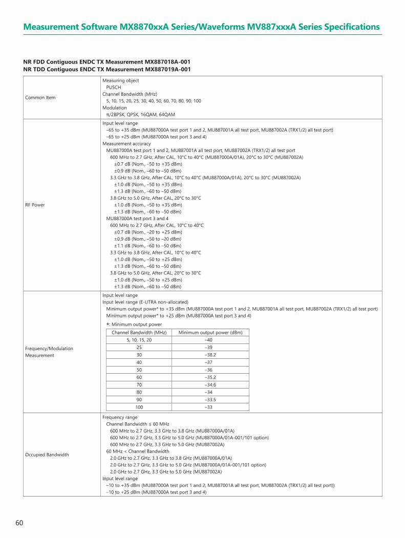
60
NR FDD Contiguous ENDC TX Measurement MX887018A-001 NR TDD Contiguous ENDC TX Measurement MX887019A-001
Common Item
Measuring objectPUSCH
Channel Bandwidth (MHz)5, 10, 15, 20, 25, 30, 40, 50, 60, 70, 80, 90, 100
Modulationπ/2BPSK, QPSK, 16QAM, 64QAM
RF Power
Input level range–65 to +35 dBm (MU887000A test port 1 and 2, MU887001A all test port, MU887002A (TRX1/2) all test port)–65 to +25 dBm (MU887000A test port 3 and 4)
Measurement accuracyMU887000A test port 1 and 2, MU887001A all test port, MU887002A (TRX1/2) all test port
600 MHz to 2.7 GHz, After CAL, 10°C to 40°C (MU887000A/01A), 20°C to 30°C (MU887002A)±0.7 dB (Nom., –50 to +35 dBm)±0.9 dB (Nom., –60 to –50 dBm)
3.3 GHz to 3.8 GHz, After CAL, 10°C to 40°C (MU887000A/01A), 20°C to 30°C (MU887002A)±1.0 dB (Nom., –50 to +35 dBm)±1.3 dB (Nom., –60 to –50 dBm)
3.8 GHz to 5.0 GHz, After CAL, 20°C to 30°C±1.0 dB (Nom., –50 to +35 dBm)±1.3 dB (Nom., –60 to –50 dBm)
MU887000A test port 3 and 4600 MHz to 2.7 GHz, After CAL, 10°C to 40°C
±0.7 dB (Nom., –20 to +25 dBm)±0.9 dB (Nom., –50 to –20 dBm)±1.1 dB (Nom., –60 to –50 dBm)
3.3 GHz to 3.8 GHz, After CAL, 10°C to 40°C±1.0 dB (Nom., –50 to +25 dBm)±1.3 dB (Nom., –60 to –50 dBm)
3.8 GHz to 5.0 GHz, After CAL, 20°C to 30°C±1.0 dB (Nom., –50 to +25 dBm)±1.3 dB (Nom., –60 to –50 dBm)
Frequency/Modulation Measurement
Input level rangeInput level range (E-UTRA non-allocated)
Minimum output power* to +35 dBm (MU887000A test port 1 and 2, MU887001A all test port, MU887002A (TRX1/2) all test port)Minimum output power* to +25 dBm (MU887000A test port 3 and 4)
*: Minimum output powerChannel Bandwidth (MHz) Minimum output power (dBm)
5, 10, 15, 20 –4025 –3930 –38.240 –3750 –3660 –35.270 –34.680 –3490 –33.5100 –33
Occupied Bandwidth
Frequency rangeChannel Bandwidth ≤ 60 MHz
600 MHz to 2.7 GHz, 3.3 GHz to 3.8 GHz (MU887000A/01A)600 MHz to 2.7 GHz, 3.3 GHz to 5.0 GHz (MU887000A/01A-001/101 option)600 MHz to 2.7 GHz, 3.3 GHz to 5.0 GHz (MU887002A)
60 MHz < Channel Bandwidth 2.0 GHz to 2.7 GHz, 3.3 GHz to 3.8 GHz (MU887000A/01A)2.0 GHz to 2.7 GHz, 3.3 GHz to 5.0 GHz (MU887000A/01A-001/101 option)2.0 GHz to 2.7 GHz, 3.3 GHz to 5.0 GHz (MU887002A)
Input level range–10 to +35 dBm (MU887000A test port 1 and 2, MU887001A all test port, MU887002A (TRX1/2) all test port))–10 to +25 dBm (MU887000A test port 3 and 4)
Measurement Software MX8870xxA Series/Waveforms MV887xxxA Series Specifications

61
Measurement Software MX8870xxA Series/Waveforms MV887xxxA Series Specifications
Adjacent Channel Leakage Power Ratio
Frequency rangeChannel Bandwidth ≤ 60 MHz
600 MHz to 2.7 GHz, 3.3 GHz to 3.8 GHz (MU887000A/01A)600 MHz to 2.7 GHz, 3.3 GHz to 5.0 GHz (MU887000A/01A-001/101 option)600 MHz to 2.7 GHz, 3.3 GHz to 5.0 GHz (MU887002A)
60 MHz < Channel Bandwidth 2.0 GHz to 2.7 GHz, 3.3 GHz to 3.8 GHz (MU887000A/01A)2.0 GHz to 2.7 GHz, 3.3 GHz to 5.0 GHz (MU887000A/01A-001/101 option)2.0 GHz to 2.7 GHz, 3.3 GHz to 5.0 GHz (MU887002A)
Input level range–10 to +35 dBm (MU887000A test port 1 and 2, MU887001A all test port)–10 to +25 dBm (MU887000A test port 3 and 4)–10 to +35 dBm (MU887002A (TRX1/2) all test port, 600 MHz ≤ f ≤ 2700 MHz)–14 to +35 dBm (MU887002A (TRX1/2) all test port, 3300 MHz ≤ f ≤ 5000 MHz)
Measurement range≥42 dB
Spectrum Emission Mask
Frequency rangeChannel Bandwidth ≤ 60 MHz
600 MHz to 2.7 GHz, 3.3 GHz to 3.8 GHz (MU887000A/01A)600 MHz to 2.7 GHz, 3.3 GHz to 5.0 GHz (MU887000A/01A-001/101 option)600 MHz to 2.7 GHz, 3.3 GHz to 5.0 GHz (MU887002A)
60 MHz < Channel Bandwidth2.0 GHz to 2.7 GHz, 3.3 GHz to 3.8 GHz (MU887000A/01A)2.0 GHz to 2.7 GHz, 3.3 GHz to 5.0 GHz (MU887000A/01A-001/101 option)2.0 GHz to 2.7 GHz, 3.3 GHz to 5.0 GHz (MU887002A)
Input level range–10 to +35 dBm (MU887000A test port 1 and 2, MU887001A all test port, MU887002A (TRX1/2) all test port))–10 to +25 dBm (MU887000A test port 3 and 4)
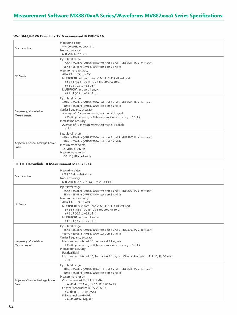
62
W-CDMA/HSPA Downlink TX Measurement MX887021A
Common Item
Measuring objectW-CDMA/HSPA downlink
Frequency range600 MHz to 2.7 GHz
RF Power
Input level range–65 to +35 dBm (MU887000A test port 1 and 2, MU887001A all test port)–65 to +25 dBm (MU887000A test port 3 and 4)
Measurement accuracyAfter CAL, 10°C to 40°CMU887000A test port 1 and 2, MU887001A all test port
±0.3 dB (typ.) (–20 to +35 dBm, 20°C to 30°C)±0.5 dB (–20 to +35 dBm)
MU887000A test port 3 and 4±0.7 dB (–15 to +25 dBm)
Frequency/Modulation Measurement
Input level range–30 to +35 dBm (MU887000A test port 1 and 2, MU887001A all test port)–30 to +25 dBm (MU887000A test port 3 and 4)
Carrier frequency accuracyAverage of 10 measurements, test model 4 signals
± (Setting frequency × Reference oscillator accuracy + 10 Hz)Modulation accuracy
Average of 10 measurements, test model 4 signals≤1%
Adjacent Channel Leakage Power Ratio
Input level range–10 to +35 dBm (MU887000A test port 1 and 2, MU887001A all test port)–10 to +25 dBm (MU887000A test port 3 and 4)
Measurement points±5 MHz, ±10 MHz
Measurement range≥55 dB (UTRA Adj./Alt.)
LTE FDD Downlink TX Measurement MX887023A
Common Item
Measuring objectLTE FDD downlink signal
Frequency range600 MHz to 2.7 GHz, 3.4 GHz to 3.8 GHz
RF Power
Input level range–65 to +35 dBm (MU887000A test port 1 and 2, MU887001A all test port)–65 to +25 dBm (MU887000A test port 3 and 4)
Measurement accuracyAfter CAL, 10°C to 40°CMU887000A test port 1 and 2, MU887001A all test port
±0.3 dB (typ.) (–20 to +35 dBm, 20°C to 30°C)±0.5 dB (–20 to +35 dBm)
MU887000A test port 3 and 4±0.7 dB (–15 to +25 dBm)
Frequency/Modulation Measurement
Input level range–15 to +35 dBm (MU887000A test port 1 and 2, MU887001A all test port)–15 to +25 dBm (MU887000A test port 3 and 4)
Carrier frequency accuracyMeasurement interval: 10, test model 3.1 signals
± (Setting frequency × Reference oscillator accuracy + 10 Hz)Modulation accuracy
Residual EVM Measurement interval: 10, Test model 3.1 signals, Channel bandwidth: 3, 5, 10, 15, 20 MHz
≤1%
Adjacent Channel Leakage Power Ratio
Input level range–10 to +35 dBm (MU887000A test port 1 and 2, MU887001A all test port)–10 to +25 dBm (MU887000A test port 3 and 4)
Measurement rangeChannel bandwidth: 1.4, 3, 5 MHz
≥54 dB (E-UTRA Adj.), ≥57 dB (E-UTRA Alt.)Channel bandwidth: 10, 15, 20 MHz
≥50 dB (E-UTRA Adj./Alt.)Full channel bandwidth
≥54 dB (UTRA Adj./Alt.)
Measurement Software MX8870xxA Series/Waveforms MV887xxxA Series Specifications

63
W-CDMA/HSPA Downlink Waveforms MV887011A
EVM≤3% rms (400 MHz ≤ f ≤ 2.7 GHz)With the MU887002A, the output signal band must be within the above-described frequency range.
GSM/EDGE Downlink Waveforms MV887012A
Phase Error≤1° rms (400 MHz ≤ f ≤ 2.7 GHz, GMSK)With the MU887002A, the output signal band must be within the above-described frequency range.
EVM≤1.8% rms (400 MHz ≤ f ≤ 2.7 GHz, 8PSK)With the MU887002A, the output signal band must be within the above-described frequency range.
LTE FDD Downlink Waveforms MV887013A
Max. Output Level
MU887000A test port 1 and 2, MU887001A all test port–12 dBm (f ≤ 3.8 GHz), –20 dBm (f > 3.8 GHz)
MU887000A test port 3 and 4–2 dBm (f ≤ 3.8 GHz), –10 dBm (f > 3.8 GHz)
MU887002A (TRX1/2) all test port–7 dBm (f ≤ 3.8 GHz), –10 dBm (f > 3.8 GHz)
EVM≤2% rms (400 MHz ≤ f ≤ 2.7 GHz), ≤3% rms (3.4 GHz ≤ f ≤ 3.8 GHz), ≤4% rms (3.8 GHz < f ≤ 6.0 GHz)With the MU887002A, the output signal band must be within the above-described frequency range.
LTE TDD Downlink Waveforms MV887014A
Max. Output Level
MU887000A test port 1 and 2, MU887001A all test port–12 dBm (f ≤ 3.8 GHz), –20 dBm (f > 3.8 GHz)
MU887000A test port 3 and 4–2 dBm (f ≤ 3.8 GHz), –10 dBm (f > 3.8 GHz)
MU887002A (TRX1/2) all test port–7 dBm (f ≤ 3.8 GHz), –10 dBm (f > 3.8 GHz)
EVM≤2% rms (400 MHz ≤ f ≤ 2.7 GHz), ≤3% rms (3.4 GHz ≤ f ≤ 3.8 GHz), ≤4% rms (3.8 GHz < f ≤ 6.0 GHz)With the MU887002A, the output signal band must be within the above-described frequency range.
CDMA2000 Forward Link Waveforms MV887015A
Waveform Quality>0.99 (400 MHz ≤ f ≤ 2.7 GHz)With the MU887002A, the output signal band must be within the above-described frequency range.
1xEV-DO Forward Link Waveforms MV887016A
Waveform Quality>0.99 (400 MHz ≤ f ≤ 2.7 GHz, Pilot channel)With the MU887002A, the output signal band must be within the above-described frequency range.
TD-SCDMA Downlink Waveforms MV887017A
EVM≤3% rms (400 MHz ≤ f ≤ 2.7 GHz)With the MU887002A, the output signal band must be within the above-described frequency range.
NR FDD sub-6 GHz Downlink Waveforms MV887018A NR TDD sub-6 GHz Downlink Waveforms MV887019A
Max. Output Level
MU887000A test port 1 and 2, MU887001A all test port–10 dBm (f ≤ 3.8 GHz), –18 dBm (f > 3.8 GHz)
MU887000A test port 3 and 40 dBm (f ≤ 3.8 GHz), –8 dBm (f > 3.8 GHz)
MU887002A (TRX1/2) all test port–5 dBm (f ≤ 3.8 GHz), –8 dBm (f > 3.8 GHz)
MU887002A (TRX1/2), when MU887002A-007 installed–5 dBm (test port 1 to 4, f ≤ 3.8 GHz)–8 dBm (test port 1 to 4, 3.8 GHz < f ≤ 6 GHz)–8 dBm (test port 5 to 12, 3.8 GHz < f < 5.9 GHz)–10 dBm (test port 5 to 12, 5.9 GHz ≤ f ≤ 7.3 GHz)
EVM≤2% rms (600 MHz ≤ f ≤ 2.7 GHz), ≤3% rms (3.3 GHz ≤ f ≤ 3.8 GHz), ≤4% rms (3.8 GHz < f ≤ 5.0 GHz, 5.9 GHz ≤ f ≤ 7.125 GHz (when MU887002A-007 installed, test port 5 to 12, Channel Edge ≤ 7.125 GHz))With the MU887002A, the output signal band must be within the above-described frequency range.
Measurement Software MX8870xxA Series/Waveforms MV887xxxA Series Specifications
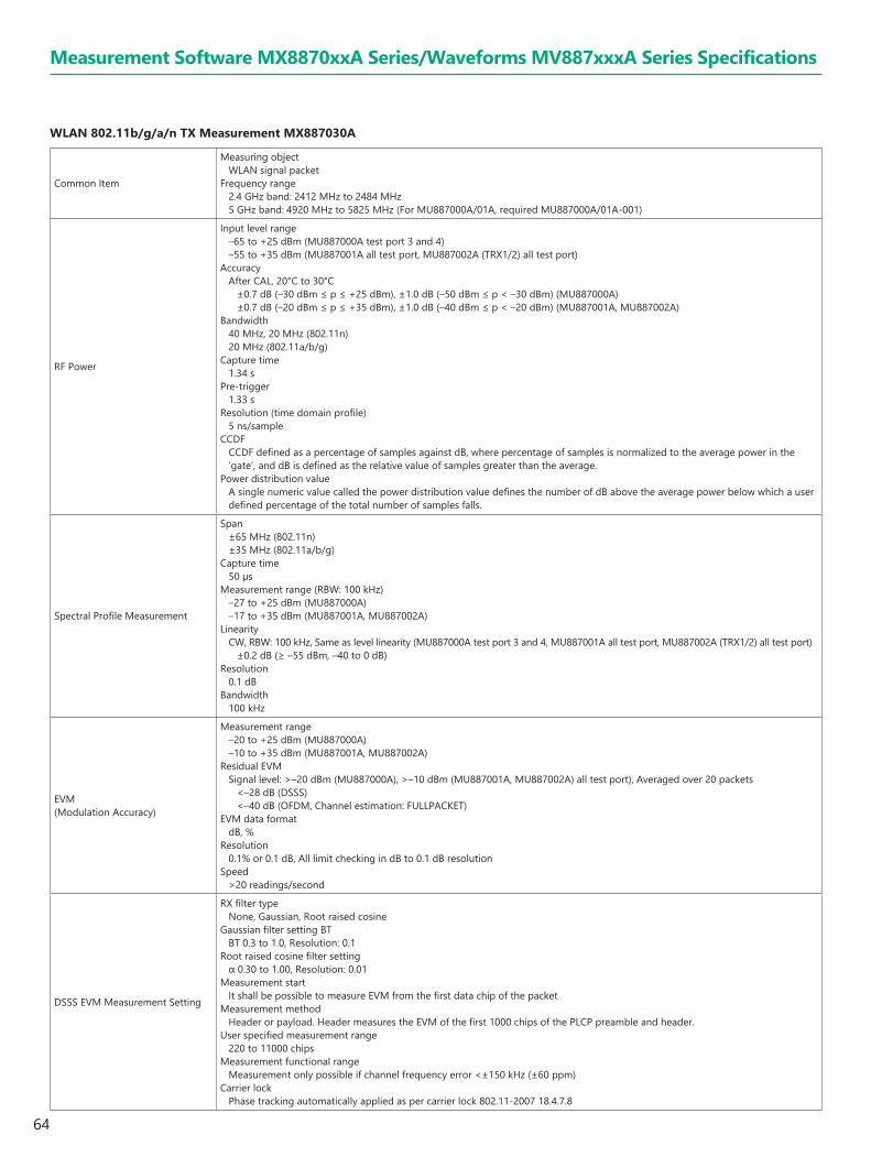
64
WLAN 802.11b/g/a/n TX Measurement MX887030A
Common Item
Measuring objectWLAN signal packet
Frequency range2.4 GHz band: 2412 MHz to 2484 MHz5 GHz band: 4920 MHz to 5825 MHz (For MU887000A/01A, required MU887000A/01A-001)
RF Power
Input level range–65 to +25 dBm (MU887000A test port 3 and 4)–55 to +35 dBm (MU887001A all test port, MU887002A (TRX1/2) all test port)
AccuracyAfter CAL, 20°C to 30°C
±0.7 dB (–30 dBm ≤ p ≤ +25 dBm), ±1.0 dB (–50 dBm ≤ p < –30 dBm) (MU887000A)±0.7 dB (–20 dBm ≤ p ≤ +35 dBm), ±1.0 dB (–40 dBm ≤ p < –20 dBm) (MU887001A, MU887002A)
Bandwidth40 MHz, 20 MHz (802.11n)20 MHz (802.11a/b/g)
Capture time1.34 s
Pre-trigger1.33 s
Resolution (time domain profile)5 ns/sample
CCDFCCDF defined as a percentage of samples against dB, where percentage of samples is normalized to the average power in the ‘gate’, and dB is defined as the relative value of samples greater than the average.
Power distribution valueA single numeric value called the power distribution value defines the number of dB above the average power below which a user defined percentage of the total number of samples falls.
Spectral Profile Measurement
Span±65 MHz (802.11n)±35 MHz (802.11a/b/g)
Capture time50 µs
Measurement range (RBW: 100 kHz)–27 to +25 dBm (MU887000A)–17 to +35 dBm (MU887001A, MU887002A)
LinearityCW, RBW: 100 kHz, Same as level linearity (MU887000A test port 3 and 4, MU887001A all test port, MU887002A (TRX1/2) all test port)
±0.2 dB (≥ –55 dBm, –40 to 0 dB)Resolution
0.1 dBBandwidth
100 kHz
EVM (Modulation Accuracy)
Measurement range–20 to +25 dBm (MU887000A)–10 to +35 dBm (MU887001A, MU887002A)
Residual EVMSignal level: >–20 dBm (MU887000A), >–10 dBm (MU887001A, MU887002A) all test port), Averaged over 20 packets
<–28 dB (DSSS) <–40 dB (OFDM, Channel estimation: FULLPACKET)
EVM data formatdB, %
Resolution0.1% or 0.1 dB, All limit checking in dB to 0.1 dB resolution
Speed>20 readings/second
DSSS EVM Measurement Setting
RX filter typeNone, Gaussian, Root raised cosine
Gaussian filter setting BTBT 0.3 to 1.0, Resolution: 0.1
Root raised cosine filter settingα 0.30 to 1.00, Resolution: 0.01
Measurement startIt shall be possible to measure EVM from the first data chip of the packet
Measurement methodHeader or payload. Header measures the EVM of the first 1000 chips of the PLCP preamble and header.
User specified measurement range220 to 11000 chips
Measurement functional rangeMeasurement only possible if channel frequency error <±150 kHz (±60 ppm)
Carrier lockPhase tracking automatically applied as per carrier lock 802.11-2007 18.4.7.8
Measurement Software MX8870xxA Series/Waveforms MV887xxxA Series Specifications

65
OFDM EVM Measurement Setting
Channel estimationUser selection of Long training sequence or Full packet.
User specified measurement range16 symbols (min.), 1000 symbols (max.)
OFDM pilot tracking“Phase tracking only” or “Phase and Amplitude tracking”. Peak and Average EVM on all sub-carriers, dB or percentagePeak and Average on each sub-carrier – frequency domain % vs. sub-carrierEVM vs. Symbol – time domain % vs. Symbol number, 1 to max
DSSS Additional Measurement
Transmit center frequency toleranceDefinition: Average frequency of the DSSS carrier signalAccuracy: ± (Setting frequency × Reference oscillator accuracy + 1 kHz)Resolution: Hz to no decimal places, ppm to one decimal place
Chip clock frequency toleranceDefinition: Frequency error relative to the 11 MHz chip clock.
Measurement averaged over a fully coded DSSS packet with minimum payload length 3300 chips, 300 µsDisplay format: Hz, ppmRange: ±50 ppmResolution: Hz to no decimal places, ppm to one decimal placeData analysis width: 20 µs (220 chips) (min.)User specified measurement range: 3300 to 30250 chips
Transmit power-on and power down rampDefinition: Time for burst to transit from 10 to 90% or 90 to 10% of linear power.Data outputs: 10%, 90%, Delta valuesResolution: 5 ns
RF carrier suppressionMethod: IEEE Std 802.11-2007 (18.4.7.7), IQ offset methodIEEE method: Relative level of the carrier to the highest sideband for a 10101010 test pattern with scrambler disabled, data rate
2 Mbps.IQ offset method: Calculated from the relative values of the peak frequency response and the channel center frequency with the
data rate processing gain.
OFDM Additional Measurement
Transmit center frequency toleranceDefinition: Average frequency of the OFDM carrier signalData output format: Hz, ppmAccuracy: ± (Setting frequency × Reference oscillator accuracy + 1 kHz) (>1 ms packet)Resolution: Hz to no decimal places, ppm to one decimal place
Symbol clock frequency toleranceDefinition: Frequency error relative to the 250 kHz symbol clock as per 19.4.7.3/17.3.9.5
Measurement averaged over a fully coded OFDM packet with a minimum payload length of 16 symbols (64 µs)Data output format: Hz, ppmRange: ±40 ppmResolution: ppm to one decimal placeUser specified measurement range: 16- (define numbers)
Transmitter center frequency leakageDefinition: Measurement of the leakage of the center carrierData output format: dBResolution: dB to two decimal places
Transmitter spectral flatnessDefinition: Measurement of RF sub-carrier power levelUnit of measurement: dB
Additional Measurement (DSSS and OFDM)
Power spectral densityThe maximum power measured in a 1 MHz bandwidth within the occupied bandwidth of the signal
Occupied bandwidthMeasures the frequency range within which the specified percentage power is contained
Occupied bandwidth percentage range1 to 99%
Measurement Software MX8870xxA Series/Waveforms MV887xxxA Series Specifications
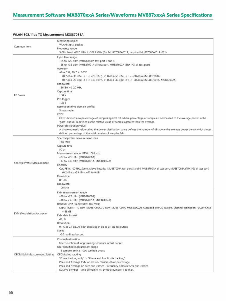
66
WLAN 802.11ac TX Measurement MX887031A
Common Item
Measuring objectWLAN signal packet
Frequency range5 GHz band: 4920 MHz to 5825 MHz (For MU887000A/01A, required MU887000A/01A-001)
RF Power
Input level range–65 to +25 dBm (MU887000A test port 3 and 4)–55 to +35 dBm (MU887001A all test port, MU887002A (TRX1/2) all test port)
AccuracyAfter CAL, 20°C to 30°C
±0.7 dB (–30 dBm ≤ p ≤ +25 dBm), ±1.0 dB (–50 dBm ≤ p < –30 dBm) (MU887000A)±0.7 dB (–20 dBm ≤ p ≤ +35 dBm), ±1.0 dB (–40 dBm ≤ p < –20 dBm) (MU887001A, MU887002A)
Bandwidth160, 80, 40, 20 MHz
Capture time1.34 s
Pre-trigger1.33 s
Resolution (time domain profile)5 ns/sample
CCDFCCDF defined as a percentage of samples against dB, where percentage of samples is normalized to the average power in the ‘gate’, and dB is defined as the relative value of samples greater than the average.
Power distribution valueA single numeric value called the power distribution value defines the number of dB above the average power below which a user defined percentage of the total number of samples falls.
Spectral Profile Measurement
Spectral profile measurement span±80 MHz
Capture time50 µs
Measurement range (RBW: 100 kHz)–27 to +25 dBm (MU887000A)–17 to +35 dBm (MU887001A, MU887002A)
LinearityCW, RBW: 100 kHz, Same as level linearity (MU887000A test port 3 and 4, MU887001A all test port, MU887002A (TRX1/2) all test port)
±0.2 dB (≥ –55 dBm, –40 to 0 dB)Resolution
0.1 dBBandwidth
100 kHz
EVM (Modulation Accuracy)
EVM measurement range–20 to +25 dBm (MU887000A)–10 to +35 dBm (MU887001A, MU887002A)
Residual EVM (Bandwidth: ≤80 MHz)Signal level: >–10 dBm (MU887000A), 0 dBm (MU887001A, MU887002A), Averaged over 20 packets, Channel estimation: FULLPACKET
<–38 dBEVM data format
dB, %Resolution
0.1% or 0.1 dB, All limit checking in dB to 0.1 dB resolutionSpeed
>20 readings/second
OFDM EVM Measurement Setting
Channel estimationUser selection of long training sequence or full packet.
User specified measurement range16 symbols (min.), 1000 symbols (max.)
OFDM pilot tracking“Phase tracking only” or “Phase and Amplitude tracking”. Peak and Average EVM on all sub-carriers, dB or percentagePeak and Average on each sub-carrier – frequency domain % vs. sub-carrierEVM vs. Symbol – time domain % vs. Symbol number, 1 to max.
Measurement Software MX8870xxA Series/Waveforms MV887xxxA Series Specifications

67
OFDM Additional Measurement
Transmit center frequency toleranceDefinition: Average frequency of the OFDM carrier signalData output format: Hz, ppmAccuracy: ± (Setting frequency × Reference oscillator accuracy + 1 kHz) (>1 ms packet)Resolution: Hz to no decimal places, ppm to one decimal places
Symbol clock frequency tolerance Definition: Frequency error relative to the 250 kHz symbol clock as per 19.4.7.3/17.3.9.5
Measurement averaged over a fully coded OFDM packet with a minimum payload length of 16 symbols (64 µs)Data output format: Hz, ppmRange: ±40 ppmResolution: ppm to one decimal placesUser specified measurement range: 16- (Define numbers)
Transmitter center frequency leakageDefinition: Measurement of the leakage of the center carrierData output format: dBResolution: dB to two decimal places
Transmitter spectral flatnessDefinition: Measurement of RF sub-carrier power levelUnit of measurement: dB
Measurement Software MX8870xxA Series/Waveforms MV887xxxA Series Specifications
WLAN 802.11p TX Measurement MX887032A (Automotive Connectivity V2X)
Common Item
Measuring objectWLAN single packet
Frequency range715 MHz to 765 MHz902 MHz to 928 MHz5725 MHz to 5925 MHz (For MU887000A/01A, required MU887000A/01A-001)
RF Power
Input level range–65 to +25 dBm (MU887000A test port 3 and 4)–55 to +35 dBm (MU887001A, MU887002A (TRX1/2) all test port)
Measurement accuracyAfter CAL, 20 to 30°C
±0.7 dB (–30 dBm ≤ p ≤ +25 dBm), ±1.0 dB (–50 dBm ≤ p < –30 dBm) (MU887000A)±0.7 dB (–20 dBm ≤ p ≤ +35 dBm), ±1.0 dB (–40 dBm ≤ p < –20 dBm) (MU887001A, MU887002A)
Bandwidth5, 10, 20 MHz
EVM (Modulation Accuracy)
Measurement range–20 to +25 dBm (MU887000A)–10 to +35 dBm (MU887001A, MU887002A)
Residual EVM (OFDM)Signal level: >–20 dBm (MU887000A), >–10 dBm (MU887001A, MU887002A), Averaged over 20 packets, Channel estimation: FULLPACKET
<–40 dBEVM data format
dB or %Measurement resolution
0.1% or 0.1 dB, All limit checking in dB to 0.1 dB resolution
OFDM EVM Measurement Setting
Channel estimationUser selection of Long training sequence or Full packet
User specified measurement range16 symbols (min.), 1000 symbols (max.)
OFDM pilot tracking“Phase tracking only” or “Phase and amplitude tracking”, default: Phase tracking onlyPeak and average EVM on all sub-carriers, dB or percentagePeak and average on each sub-carrier – frequency domain % vs. sub-carrierEVM vs. Symbol – time domain % vs. Symbol number, 1 to max
OFDM Additional Measurement
Transmit center frequency toleranceDefinition: Average frequency of the OFDM carrier signalData output format: Hz and ppmMeasurement accuracy: ± (Setting frequency × Reference oscillator accuracy + 1 kHz) (packet: >1 ms)Resolution: Hz to no decimal places, ppm to 1 decimal place
Transmit center frequency leakageDefinition: Measurement of the leakage of the center carrierData output format: dBResolution: dB to two decimal places
Transmitter spectral flatnessDefinition: Measurement of RF sub-carrier power levelData output format: dB
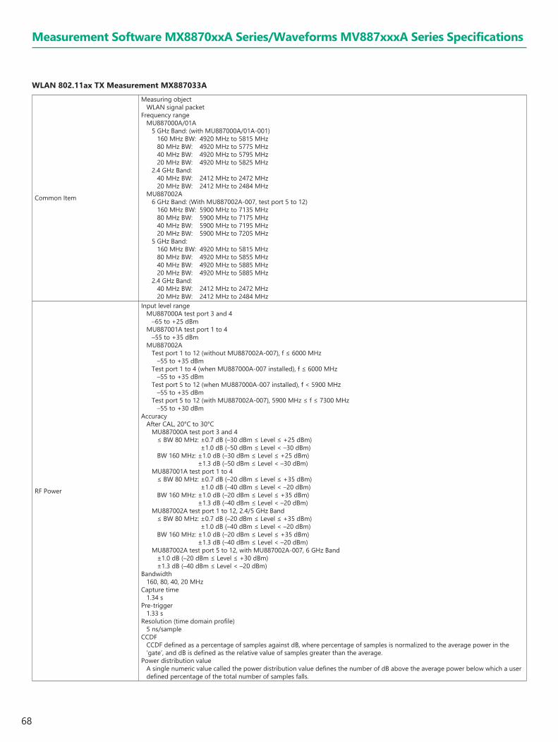
68
Measurement Software MX8870xxA Series/Waveforms MV887xxxA Series Specifications
WLAN 802.11ax TX Measurement MX887033A
Common Item
Measuring objectWLAN signal packet
Frequency rangeMU887000A/01A
5 GHz Band: (with MU887000A/01A-001)160 MHz BW: 4920 MHz to 5815 MHz80 MHz BW: 4920 MHz to 5775 MHz40 MHz BW: 4920 MHz to 5795 MHz20 MHz BW: 4920 MHz to 5825 MHz
2.4 GHz Band: 40 MHz BW: 2412 MHz to 2472 MHz20 MHz BW: 2412 MHz to 2484 MHz
MU887002A6 GHz Band: (With MU887002A-007, test port 5 to 12)
160 MHz BW: 5900 MHz to 7135 MHz80 MHz BW: 5900 MHz to 7175 MHz40 MHz BW: 5900 MHz to 7195 MHz20 MHz BW: 5900 MHz to 7205 MHz
5 GHz Band:160 MHz BW: 4920 MHz to 5815 MHz80 MHz BW: 4920 MHz to 5855 MHz40 MHz BW: 4920 MHz to 5885 MHz20 MHz BW: 4920 MHz to 5885 MHz
2.4 GHz Band: 40 MHz BW: 2412 MHz to 2472 MHz20 MHz BW: 2412 MHz to 2484 MHz
RF Power
Input level rangeMU887000A test port 3 and 4
–65 to +25 dBmMU887001A test port 1 to 4
–55 to +35 dBmMU887002A
Test port 1 to 12 (without MU887002A-007), f ≤ 6000 MHz–55 to +35 dBm
Test port 1 to 4 (when MU887000A-007 installed), f ≤ 6000 MHz–55 to +35 dBm
Test port 5 to 12 (when MU887000A-007 installed), f < 5900 MHz–55 to +35 dBm
Test port 5 to 12 (with MU887002A-007), 5900 MHz ≤ f ≤ 7300 MHz–55 to +30 dBm
AccuracyAfter CAL, 20°C to 30°C
MU887000A test port 3 and 4≤ BW 80 MHz: ±0.7 dB (–30 dBm ≤ Level ≤ +25 dBm)
±1.0 dB (–50 dBm ≤ Level < –30 dBm)BW 160 MHz: ±1.0 dB (–30 dBm ≤ Level ≤ +25 dBm)
±1.3 dB (–50 dBm ≤ Level < –30 dBm)MU887001A test port 1 to 4
≤ BW 80 MHz: ±0.7 dB (–20 dBm ≤ Level ≤ +35 dBm) ±1.0 dB (–40 dBm ≤ Level < –20 dBm)
BW 160 MHz: ±1.0 dB (–20 dBm ≤ Level ≤ +35 dBm) ±1.3 dB (–40 dBm ≤ Level < –20 dBm)
MU887002A test port 1 to 12, 2.4/5 GHz Band≤ BW 80 MHz: ±0.7 dB (–20 dBm ≤ Level ≤ +35 dBm)
±1.0 dB (–40 dBm ≤ Level < –20 dBm)BW 160 MHz: ±1.0 dB (–20 dBm ≤ Level ≤ +35 dBm)
±1.3 dB (–40 dBm ≤ Level < –20 dBm)MU887002A test port 5 to 12, with MU887002A-007, 6 GHz Band
±1.0 dB (–20 dBm ≤ Level ≤ +30 dBm)±1.3 dB (–40 dBm ≤ Level < –20 dBm)
Bandwidth160, 80, 40, 20 MHz
Capture time1.34 s
Pre-trigger1.33 s
Resolution (time domain profile)5 ns/sample
CCDFCCDF defined as a percentage of samples against dB, where percentage of samples is normalized to the average power in the ‘gate’, and dB is defined as the relative value of samples greater than the average.
Power distribution valueA single numeric value called the power distribution value defines the number of dB above the average power below which a user defined percentage of the total number of samples falls.

69
Measurement Software MX8870xxA Series/Waveforms MV887xxxA Series Specifications
Spectral Profile Measurement
Spectral profile measurement span±80 MHz
Capture time50 μs
Measurement range (RBW: 100 kHz)MU887000A test port 3 and 4
–27 to +25 dBmMU887001A test port 1 to 4
–17 to +35 dBmMU887002A test port 1 to 12, Setting Frequency 2.4/5 GHz Band
–17 to +35 dBmMU887002A test port 5 to 12, with MU887002A-007, Setting Frequency 6 GHz Band
–17 to +30 dBmLinearity
CW, RBW: 100 kHz±0.2 dB (≥ –55 dBm, –40 to 0 dB)
Resolution0.1 dB
Bandwidth100 kHz
EVM (Modulation Accuracy)
EVM measurement rangeMU887000A test port 3 and 4
–20 to +25 dBmMU887001A test port 1 to 4
–10 to +35 dBmMU887002A test port 1 to 12, Setting Frequency 2.4/5 GHz Band
–10 to +35 dBmMU887002A test port 5 to 12, with MU887002A-007, Setting Frequency 6 GHz Band
–10 to +30 dBmResidual EVM
20°C to 30°CSignal level: >–10 dBm (MU887000A), 0 dBm (MU887001A, MU887002A), averaged over 20 packets, where each packet is no less
than 16 data OFDM symbols long.And for each subcarrier except Pilots, all data OFDM symbol should have same data field pattern.Channel estimation: FULLPACKET
<–45 dB, Measured at 5210 MHzMU887000A Test port 3 and 4, MU887001A Test port 1 to 4
<–40 dB (≤BW 80 MHz)<–40 dB (BW 160 MHz, Nom.)
MU887002A test port 1 to 12, 2.4/5 GHz Band, <–40 dB (≤BW 80 MHz)<–43 dB (BW 160 MHz, Nom.)
MU887002A test port 5 to 12, with MU887002A-007 installed, 6 GHz Band<–45 dB (≤BW 80 MHz, Nom.)<–41 dB (BW 160 MHz, Nom.)
EVM data formatdB, %
Resolution0.1% or 0.1 dB, All limit checking in dB to 0.1 dB resolution
OFDM EVM Measurement Setting
Channel estimationUser selection of long training sequence or full packet.
User specified measurement range16 symbols (min.), 1000 symbols (max.)
OFDM pilot tracking“Phase tracking only” or “Phase and Amplitude tracking”.Peak and Average EVM on all sub-carriers, dB or percentagePeak and Average on each sub-carrier – frequency domain % vs. sub-carrierEVM vs. Symbol – time domain % vs. Symbol number, 1 to max.
OFDM Additional Measurement
Transmit center frequency toleranceDefinition: Average frequency of the OFDM carrier signalData output format: Hz, ppmAccuracy: ± (Setting frequency × Reference oscillator accuracy + 1 kHz) (>1 ms packet)Resolution: Hz to no decimal places, ppm to one decimal places
Symbol clock frequency toleranceDefinition: Frequency error relative to the symbol clock depends on Signal’s Guard interval.If GI is 0.8 us, Symbol Clock is (1 / (12.8 us + 0.8 us)) = 73.529 kHz approx.If GI is 1.6 us, Symbol Clock is (1 / (12.8 us + 1.6 us)) = 69.444 kHz approx.If GI is 3.2 us, Symbol Clock is (1 / (12.8 us + 3.2 us)) = 62.500 kHz approx.Measurement averaged over a fully coded OFDM packet with a minimum payload length of 16 symbols.Data output format: Hz, ppmRange: ±40 ppmResolution: ppm to one decimal placesUser specified measurement range: 16- (Define numbers)
Transmitter center frequency leakageDefinition: Measurement of the leakage of the center carrierData output format: dBResolution: dB to two decimal places
Transmitter spectral flatnessDefinition: Measurement of RF sub-carrier power levelUnit of measurement: dB
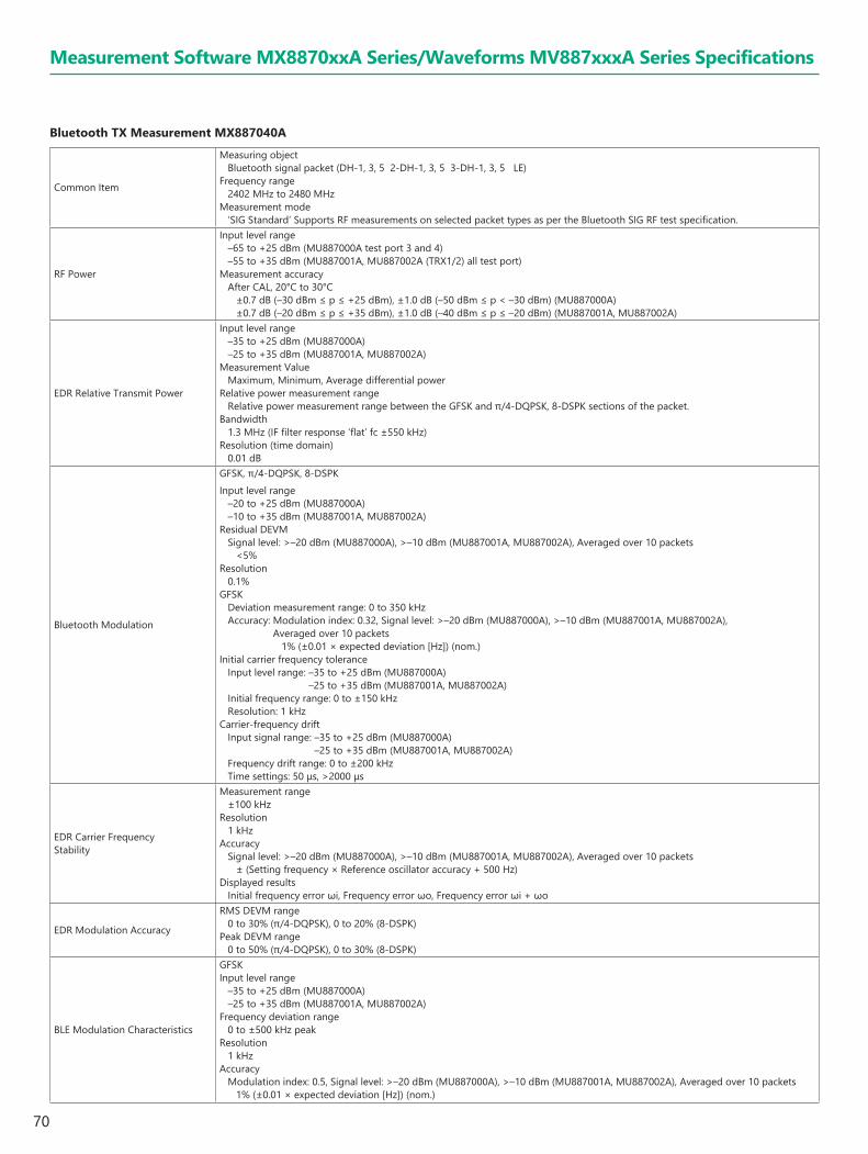
70
Bluetooth TX Measurement MX887040A
Common Item
Measuring objectBluetooth signal packet (DH-1, 3, 5 2-DH-1, 3, 5 3-DH-1, 3, 5 LE)
Frequency range2402 MHz to 2480 MHz
Measurement mode‘SIG Standard’ Supports RF measurements on selected packet types as per the Bluetooth SIG RF test specification.
RF Power
Input level range–65 to +25 dBm (MU887000A test port 3 and 4)–55 to +35 dBm (MU887001A, MU887002A (TRX1/2) all test port)
Measurement accuracyAfter CAL, 20°C to 30°C
±0.7 dB (–30 dBm ≤ p ≤ +25 dBm), ±1.0 dB (–50 dBm ≤ p < –30 dBm) (MU887000A)±0.7 dB (–20 dBm ≤ p ≤ +35 dBm), ±1.0 dB (–40 dBm ≤ p ≤ –20 dBm) (MU887001A, MU887002A)
EDR Relative Transmit Power
Input level range–35 to +25 dBm (MU887000A)–25 to +35 dBm (MU887001A, MU887002A)
Measurement ValueMaximum, Minimum, Average differential power
Relative power measurement rangeRelative power measurement range between the GFSK and π/4-DQPSK, 8-DSPK sections of the packet.
Bandwidth1.3 MHz (IF filter response ‘flat’ fc ±550 kHz)
Resolution (time domain)0.01 dB
Bluetooth Modulation
GFSK, π/4-DQPSK, 8-DSPKInput level range
–20 to +25 dBm (MU887000A)–10 to +35 dBm (MU887001A, MU887002A)
Residual DEVMSignal level: >–20 dBm (MU887000A), >–10 dBm (MU887001A, MU887002A), Averaged over 10 packets
<5%Resolution
0.1%GFSK
Deviation measurement range: 0 to 350 kHzAccuracy: Modulation index: 0.32, Signal level: >–20 dBm (MU887000A), >–10 dBm (MU887001A, MU887002A),
Averaged over 10 packets 1% (±0.01 × expected deviation [Hz]) (nom.)
Initial carrier frequency toleranceInput level range: –35 to +25 dBm (MU887000A)
–25 to +35 dBm (MU887001A, MU887002A)Initial frequency range: 0 to ±150 kHzResolution: 1 kHz
Carrier-frequency driftInput signal range: –35 to +25 dBm (MU887000A)
–25 to +35 dBm (MU887001A, MU887002A)Frequency drift range: 0 to ±200 kHzTime settings: 50 μs, >2000 μs
EDR Carrier Frequency Stability
Measurement range±100 kHz
Resolution1 kHz
AccuracySignal level: >–20 dBm (MU887000A), >–10 dBm (MU887001A, MU887002A), Averaged over 10 packets
± (Setting frequency × Reference oscillator accuracy + 500 Hz)Displayed results
Initial frequency error ωi, Frequency error ωo, Frequency error ωi + ωo
EDR Modulation Accuracy
RMS DEVM range0 to 30% (π/4-DQPSK), 0 to 20% (8-DSPK)
Peak DEVM range0 to 50% (π/4-DQPSK), 0 to 30% (8-DSPK)
BLE Modulation Characteristics
GFSKInput level range
–35 to +25 dBm (MU887000A)–25 to +35 dBm (MU887001A, MU887002A)
Frequency deviation range0 to ±500 kHz peak
Resolution1 kHz
AccuracyModulation index: 0.5, Signal level: >–20 dBm (MU887000A), >–10 dBm (MU887001A, MU887002A), Averaged over 10 packets
1% (±0.01 × expected deviation [Hz]) (nom.)
Measurement Software MX8870xxA Series/Waveforms MV887xxxA Series Specifications

71
Measurement Software MX8870xxA Series/Waveforms MV887xxxA Series Specifications
Short Range Wireless Average Power and Frequency Measurement MX887050A
RF Power (CW and Continuously Modulated)
Frequency range2.4 GHz band: 2402 MHz to 2484 MHz5 GHz band: 4920 MHz to 5825 MHz (For MU887000A/01A, required MU887000A/01A-001)
Input level range–65 to +25 dBm (MU887000A test port 3 and 4)–55 to +35 dBm (MU887001A, MU887002A)
AccuracyAfter CAL400 MHz ≤ f < 3.8 GHz, 10°C to 40°C
±0.7 dB (–30 ≤ p ≤ +25 dBm)±0.9 dB (–55 ≤ p < –30 dBm)±1.1 dB (–65 ≤ p < –55 dBm)
3.8 GHz ≤ f ≤ 6 GHz, 20°C to 30°C±0.7 dB (–30 ≤ p ≤ +25 dBm)±0.9 dB (–55 ≤ p < –30 dBm)±1.1 dB (–65 ≤ p < –55 dBm)
LinearityCW, RBW: 100 kHz
±0.2 dB (≥–55 dBm, –40 to 0 dB)
Frequency (CW)
Input level range–35 to +25 dBm (MU887000A)–25 to +35 dBm (MU887001A, MU887002A)
Frequency range0 to ±500 kHz
Accuracy± (Setting frequency × Reference oscillator accuracy + 500 Hz)
IEEE 802.15.4 TX Measurement MX887060A
Common ItemFrequency range
440 MHz to 2500 MHz
RF Power
Input level range–65 to +35 dBm (MU887000A test port 1 and 2, MU887001A all test port)–65 to +25 dBm (MU887000A test port 3 and 4)
AccuracyAfter CAL, 10°C to 40°CMU887000A test port 1 and 2, MU887001A all test port
±0.3 dB (typ.), ±0.5 dB (–25 to +35 dBm)±0.7 dB (–55 to –25 dBm)±0.9 dB (–65 to –55 dBm)
MU887000A test port 3 and 4±0.7 dB (–25 to +25 dBm)±0.9 dB (–55 to –25 dBm)±1.1 dB (–65 to –55 dBm)
Modulation Analysis
Input level rangeAnalysis length: 1000 chips or more
–30 to +35 dBm (MU887000A test port 1 and 2, MU887001A all test port)–30 to +25 dBm (MU887000A test port 3 and 4)
Modulation accuracyResidual EVM
≤1.5%Carrier frequency accuracy
± (Setting frequency × Reference oscillator accuracy + 20 Hz)
BLE Carrier Frequency Offset and Drift
Input level range–35 to +25 dBm (MU887000A)–25 to +35 dBm (MU887001A, MU887002A)
Frequency range0 to ±500 kHz
AccuracySignal level: >–20 dBm (MU887000A), >–10 dBm (MU887001A, MU887002A), Averaged over 10 packets
± (Setting frequency × Reference oscillator accuracy + 500 Hz)Displayed results
Carrier frequency error, Frequency drift, Drift rate

72
Z-Wave TX Measurement MX887061A
Common Item Frequency range440 MHz to 1000 MHz
RF Power
Input level range–65 to +35 dBm (MU887000A test port 1 and 2, MU887001A all test port)–65 to +25 dBm (MU887000A test port 3 and 4)
AccuracyAfter CAL, 10°C to 40°CMU887000A test port 1 and 2, MU887001A all test port
±0.3 dB (typ.), ±0.5 dB (–25 to +35 dBm)±0.7 dB (–55 to –25 dBm)±0.9 dB (–65 to –55 dBm)
MU887000A test port 3 and 4±0.7 dB (–25 to +25 dBm)±0.9 dB (–55 to –25 dBm)±1.1 dB (–65 to –55 dBm)
Modulation Analysis
Input level rangeAnalysis length: 200 bits
–30 to +35 dBm (MU887000A test port 1 and 2, MU887001A all test port)–30 to +25 dBm (MU887000A test port 3 and 4)
Carrier frequency accuracy± (Setting frequency × Reference oscillator accuracy + 20 Hz)
Category M FDD Uplink TX Measurement MX887065A
Common Item
Measuring ObjectPUSCH, PUCCH
Frequency Range600 MHz to 2.7 GHz, 3.4 GHz to 3.8 GHz600 MHz to 2.7 GHz, 3.4 GHz to 4.2 GHz (For MU887000A/01A, required MU887000A/01A-001)
RF Power
Input Level Range–65 to +35 dBm (MU887000A test port 1 and 2, MU887001A all test port)–65 to +25 dBm (MU887000A test port 3 and 4)
Measurement Accuracy600 MHz to 2.7 GHz, 3.4 GHz to 3.8 GHz, After CAL, 10°C to 40°CMU887000A test port 1 and 2, MU887001A all test port
±0.3 dB (typ.) (–20 to +35 dBm, 20°C to 30°C)±0.5 dB (–20 to +35 dBm)±0.7 dB (–50 to –20 dBm)±0.9 dB (–60 to –50 dBm)
MU887000A test port 3 and 4±0.7 dB (–20 to +25 dBm)±0.9 dB (–50 to –20 dBm)±1.1 dB (–60 to –50 dBm)
3.8 GHz to 4.2 GHz, After CAL, 20°C to 30°CMU887000A test port 1 and 2, MU887001A all test port
±0.7 dB (–20 to +35 dBm)±0.9 dB (–50 to –20 dBm)±1.1 dB (–60 to –50 dBm)
MU887000A test port 3 and 4±0.7 dB (–20 to +25 dBm)±0.9 dB (–50 to –20 dBm)±1.1 dB (–60 to –50 dBm)
Frequency/Modulation Measurement
Input Level Range–40 to +35 dBm (MU887000A test port 1 and 2, MU887001A all test port)–40 to +25 dBm (MU887000A test port 3 and 4)
Carrier Frequency Accuracy± (Setting frequency × Reference oscillator accuracy + 15 Hz)
Modulation AnalysisResidual EVM: Average of 20 measurements
≤2.5%In-Band Emission
In signal condition with Input Level ≥–10 dBm≤–40 dBc
Measurement Software MX8870xxA Series/Waveforms MV887xxxA Series Specifications

73
Measurement Software MX8870xxA Series/Waveforms MV887xxxA Series Specifications
Occupied bandwidthInput Level Range
–10 to +35 dBm (MU887000A test port 1 and 2, MU887001A all test port)–10 to +25 dBm (MU887000A test port 3 and 4)
Adjacent channel leakage power ratio
Input Level Range–10 to +35 dBm (MU887000A test port 1 and 2, MU887001A all test port)–10 to +25 dBm (MU887000A test port 3 and 4)
Measurement Range≥45 dB (E-UTRA ACLR1)≥50 dB (UTRA ACLR1)≥55 dB (UTRA ACLR2)
Spectrum Emission MaskInput Level Range
–10 to +35 dBm (MU887000A test port 1 and 2, MU887001A all test port)–10 to +25 dBm (MU887000A test port 3 and 4)
NB-IoT Uplink TX Measurement MX887067A
Common Item
Measuring objectNPUSCH
Frequency range600 MHz to 2.7 GHz, 3.4 GHz to 3.8 GHz600 MHz to 2.7 GHz, 3.4 GHz to 4.2 GHz (For MU887000A/01A, required MU887000A/01A-001)
RF Power
Input level range–65 to +35 dBm (MU887000A test port 1 and 2, MU887001A all test port) –65 to +25 dBm (MU887000A test port 3 and 4)
Measurement accuracy600 MHz to 2.7 GHz, 3.4 GHz to 3.8 GHz, After CAL, 10°C to 40°CMU887000A test port 1 and 2, MU887001A all test port
±0.3 dB (typ.) (–20 to +35 dBm, 20°C to 30°C)±0.5 dB (–20 to +35 dBm)±0.7 dB (–50 to –20 dBm)±0.9 dB (–60 to –50 dBm)
MU887000A test port 3 and 4±0.7 dB (–20 to +25 dBm)±0.9 dB (–50 to –20 dBm)±1.1 dB (–60 to –50 dBm)
3.8 GHz to 4.2 GHz, After CAL, 20°C to 30°CMU887000A test port 1 and 2, MU887001A all test port
±0.7 dB (–20 to +35 dBm)±0.9 dB (–50 to –20 dBm)±1.1 dB (–60 to –50 dBm)
MU887000A test port 3 and 4±0.7 dB (–20 to +25 dBm)±0.9 dB (–50 to –20 dBm)±1.1 dB (–60 to –50 dBm)
Frequency/Modulation Measurement
Input level range–40 to +35 dBm (MU887000A test port 1 and 2, MU887001A all test port)–40 to +25 dBm (MU887000A test port 3 and 4)
Carrier frequency accuracy ± (Setting frequency × Reference oscillator accuracy + 15 Hz)
Modulation analysisResidual EVM: Average of 20 measurements
≤1%In-band emission
In signal condition with Input Level ≥–10 dBm≤–40 dBc
Occupied BandwidthInput level range
–10 to +35 dBm (MU887000A test port 1 and 2, MU887001A all test port)–10 to +25 dBm (MU887000A test port 3 and 4)
Adjacent Channel Leakage Power Ratio
Input level range–10 to +35 dBm (MU887000A test port 1 and 2, MU887001A all test port)–10 to +25 dBm (MU887000A test port 3 and 4)
Measurement range≥47 dB (GSM ACLR)≥50 dB (UTRA ACLR)
Spectrum Emission MaskInput level range
–10 to +35dBm (MU887000A test port 1 and 2, MU887001A all test port)–10 to +25dBm (MU887000A test port 3 and 4)
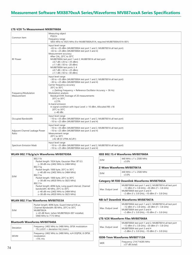
74
Measurement Software MX8870xxA Series/Waveforms MV887xxxA Series Specifications
LTE-V2X Tx Measurement MX887068A
Common Item
Measuring objectPSSCH
Frequency range5855 MHz to 5925 MHz (For MU887000A/01A, required MU887000A/01A-001)
RF Power
Input level range–65 to +35 dBm (MU887000A test port 1 and 2, MU887001A all test port) –65 to +25 dBm (MU887000A test port 3 and 4)
Measurement accuracyAfter CAL, 20°C to 30°CMU887000A test port 1 and 2, MU887001A all test port
±0.7 dB (–20 to +35 dBm)±1.1 dB (–50 to –20 dBm)
MU887000A test ports 3, 4 ±0.7 dB (–30 to +25 dBm)±1.1 dB (–50 to –30 dBm)
Frequency/Modulation Measurement
Input level range–30 to +35 dBm (MU887000A test port 1 and 2, MU887001A all test port)–30 to +25 dBm (MU887000A test port 3 and 4)
Carrier frequency accuracy 20°C to 30°C
± (Setting Frequency × Reference Oscillator Accuracy + 36 Hz)Modulation analysis
Residual EVM: Average of 20 measurements20°C to 30°C
≤2.5%In-band emission
In signal condition with Input Level ≥–10 dBm, Allocated RB ≤1820°C to 30°C
≤–40 dBc
Occupied BandwidthInput level range
–10 to +35 dBm (MU887000A test port 1 and 2, MU887001A all test port)–10 to +25 dBm (MU887000A test port 3 and 4)
Adjacent Channel Leakage Power Ratio
Input level range–10 to +35 dBm (MU887000A test port 1 and 2, MU887001A all test port)–10 to +25 dBm (MU887000A test port 3 and 4)
Measurement range20°C to 30°C
≥42 dB (E-UTRA ACLR1)
Spectrum Emission MaskInput level range
–10 to +35 dBm (MU887000A test port 1 and 2, MU887001A all test port)–10 to +25 dBm (MU887000A test port 3 and 4)
WLAN 802.11b/g/a/n Waveforms MV887030A
EVM
802.11bPacket length: 1024 byte, Gaussian filter: BT 0.5
≤–38 dB rms (2402 MHz to 2484 MHz)802.11g
Packet length: 1000 byte, 20°C to 30°C≤–40 dB rms (2402 MHz to 2484 MHz)
802.11aPacket length: 1000 byte, 20°C to 30°C
≤–38 dB rms (4920 MHz to 5825 MHz)802.11n
Packet length: 4096 byte, Long guard interval, Channel bandwidth: 40 MHz, 20°C to 30°C
≤–40 dB rms (2402 MHz to 2484 MHz)≤–38 dB rms (4920 MHz to 5825 MHz)
WLAN 802.11ax Waveforms MV887033A
EVM
Packet length: 4096 byte, Guard Interval 0.8 µs, Channel Bandwidth: 80 MHz, 20°C to 30°CMU887002A
≤–43 dB Nom. (when MU887002A-007 installed, 5900 MHz to 7175 MHz)
Bluetooth Waveforms MV887040A
Deviation Frequency: 2402 MHz to 2480 MHz, GFSK modulation1% (±0.01 × deviation Hz) (nom.)
DEVMFrequency: 2402 MHz to 2480 MHz, π/4-DQPSK, 8-DPSK modulation
<5% rms
IEEE 802.15.4 Waveforms MV887060A
EVM 440 MHz ≤ f ≤ 2500 MHz≤3.0%
Z-Wave Waveforms MV887061A
EVM 440 MHz ≤ f ≤ 2500 MHz≤3.0%
Category M FDD Downlink Waveforms MV887065A
Max. Output Level
MU887000A test port 1 and 2, MU887001A all test port–12 dBm (f ≤ 3.8 GHz), –20 dBm (f > 3.8 GHz)
MU887000A test port 3 and 4–2 dBm (f ≤ 3.8 GHz), –10 dBm (f > 3.8 GHz)
NB-IoT Downlink Waveforms MV887067A
Max. Output Level
MU887000A test port 1 and 2, MU887001A all test port–12 dBm (f ≤ 3.8 GHz), –20 dBm (f > 3.8 GHz)
MU887000A test port 3 and 4–2 dBm (f ≤ 3.8 GHz), –10 dBm (f > 3.8 GHz)
LTE-V2X Waveform Files MV887068A
Max. Output Level
MU887000A test port 1 and 2, MU887001A all test port–12 dBm (f ≤ 3.8 GHz), –20 dBm (f > 3.8 GHz)
MU887000A test port 3 and 4–2 dBm (f ≤ 3.8 GHz), –10 dBm (f > 3.8 GHz)
ISDB-Tmm Waveforms MV887112A
MER Frequency: 214.714285 MHz≥37 dB (total)
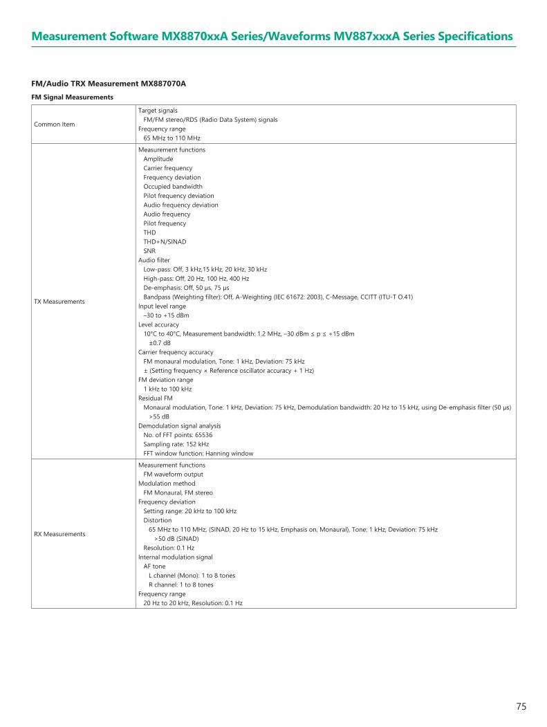
75
FM/Audio TRX Measurement MX887070A FM Signal Measurements
Common Item
Target signalsFM/FM stereo/RDS (Radio Data System) signals
Frequency range65 MHz to 110 MHz
TX Measurements
Measurement functionsAmplitude Carrier frequency Frequency deviation Occupied bandwidthPilot frequency deviation Audio frequency deviation Audio frequency Pilot frequency THDTHD+N/SINADSNR
Audio filterLow-pass: Off, 3 kHz,15 kHz, 20 kHz, 30 kHzHigh-pass: Off, 20 Hz, 100 Hz, 400 HzDe-emphasis: Off, 50 µs, 75 µsBandpass (Weighting filter): Off, A-Weighting (IEC 61672: 2003), C-Message, CCITT (ITU-T O.41)
Input level range–30 to +15 dBm
Level accuracy10°C to 40°C, Measurement bandwidth: 1.2 MHz, –30 dBm ≤ p ≤ +15 dBm
±0.7 dBCarrier frequency accuracy
FM monaural modulation, Tone: 1 kHz, Deviation: 75 kHz± (Setting frequency × Reference oscillator accuracy + 1 Hz)
FM deviation range1 kHz to 100 kHz
Residual FMMonaural modulation, Tone: 1 kHz, Deviation: 75 kHz, Demodulation bandwidth: 20 Hz to 15 kHz, using De-emphasis filter (50 µs)
>55 dBDemodulation signal analysis
No. of FFT points: 65536Sampling rate: 152 kHzFFT window function: Hanning window
RX Measurements
Measurement functionsFM waveform output
Modulation methodFM Monaural, FM stereo
Frequency deviationSetting range: 20 kHz to 100 kHzDistortion
65 MHz to 110 MHz, (SINAD, 20 Hz to 15 kHz, Emphasis on, Monaural), Tone: 1 kHz, Deviation: 75 kHz>50 dB (SINAD)
Resolution: 0.1 HzInternal modulation signal
AF tone L channel (Mono): 1 to 8 tonesR channel: 1 to 8 tones
Frequency range20 Hz to 20 kHz, Resolution: 0.1 Hz
Measurement Software MX8870xxA Series/Waveforms MV887xxxA Series Specifications
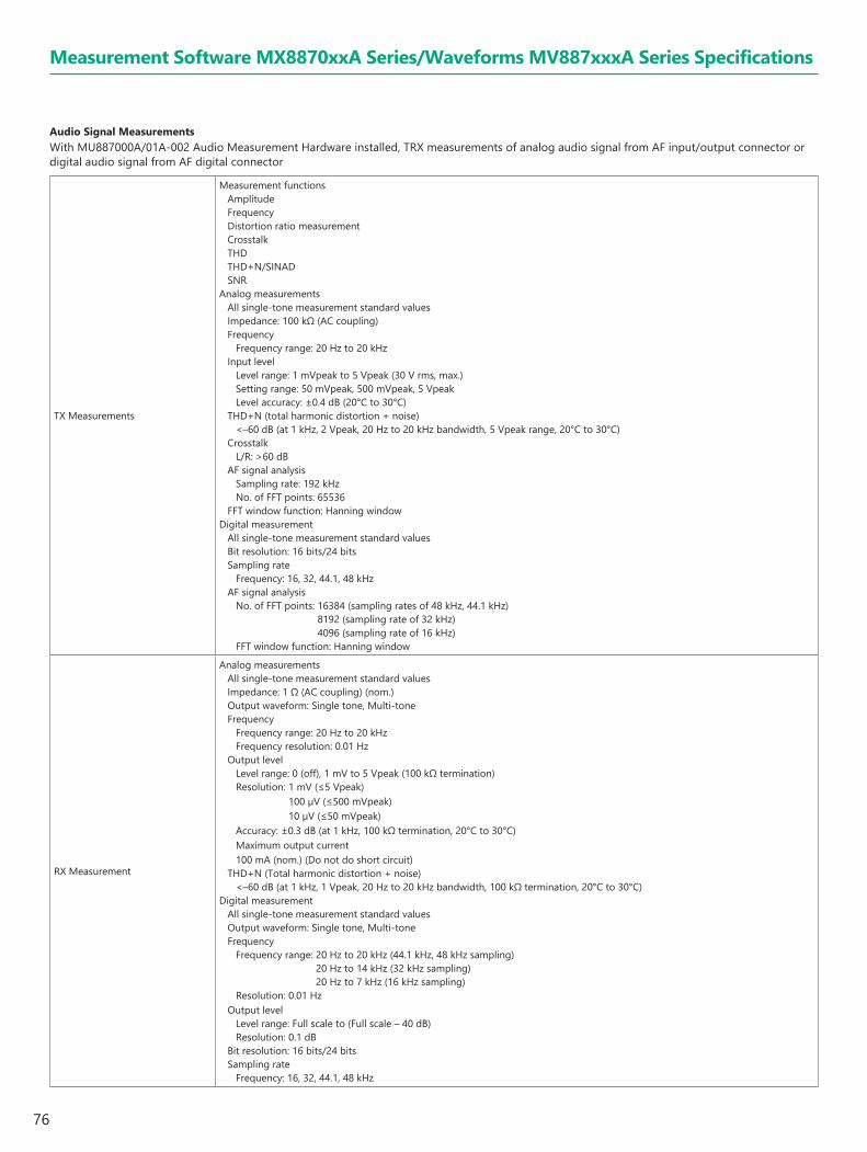
76
Audio Signal MeasurementsWith MU887000A/01A-002 Audio Measurement Hardware installed, TRX measurements of analog audio signal from AF input/output connector or digital audio signal from AF digital connector
TX Measurements
Measurement functionsAmplitude Frequency Distortion ratio measurement Crosstalk THDTHD+N/SINADSNR
Analog measurementsAll single-tone measurement standard valuesImpedance: 100 kΩ (AC coupling)Frequency
Frequency range: 20 Hz to 20 kHzInput level
Level range: 1 mVpeak to 5 Vpeak (30 V rms, max.)Setting range: 50 mVpeak, 500 mVpeak, 5 VpeakLevel accuracy: ±0.4 dB (20°C to 30°C)
THD+N (total harmonic distortion + noise)<–60 dB (at 1 kHz, 2 Vpeak, 20 Hz to 20 kHz bandwidth, 5 Vpeak range, 20°C to 30°C)
CrosstalkL/R: >60 dB
AF signal analysisSampling rate: 192 kHzNo. of FFT points: 65536
FFT window function: Hanning windowDigital measurement
All single-tone measurement standard valuesBit resolution: 16 bits/24 bitsSampling rate
Frequency: 16, 32, 44.1, 48 kHzAF signal analysis
No. of FFT points: 16384 (sampling rates of 48 kHz, 44.1 kHz) 8192 (sampling rate of 32 kHz) 4096 (sampling rate of 16 kHz)
FFT window function: Hanning window
RX Measurement
Analog measurementsAll single-tone measurement standard valuesImpedance: 1 Ω (AC coupling) (nom.)Output waveform: Single tone, Multi-toneFrequency
Frequency range: 20 Hz to 20 kHzFrequency resolution: 0.01 Hz
Output levelLevel range: 0 (off), 1 mV to 5 Vpeak (100 kΩ termination)Resolution: 1 mV (≤5 Vpeak)
100 µV (≤500 mVpeak) 10 µV (≤50 mVpeak)
Accuracy: ±0.3 dB (at 1 kHz, 100 kΩ termination, 20°C to 30°C)Maximum output current100 mA (nom.) (Do not do short circuit)
THD+N (Total harmonic distortion + noise)<–60 dB (at 1 kHz, 1 Vpeak, 20 Hz to 20 kHz bandwidth, 100 kΩ termination, 20°C to 30°C)
Digital measurementAll single-tone measurement standard valuesOutput waveform: Single tone, Multi-toneFrequency
Frequency range: 20 Hz to 20 kHz (44.1 kHz, 48 kHz sampling) 20 Hz to 14 kHz (32 kHz sampling) 20 Hz to 7 kHz (16 kHz sampling)
Resolution: 0.01 HzOutput level
Level range: Full scale to (Full scale – 40 dB)Resolution: 0.1 dB
Bit resolution: 16 bits/24 bitsSampling rate
Frequency: 16, 32, 44.1, 48 kHz
Measurement Software MX8870xxA Series/Waveforms MV887xxxA Series Specifications
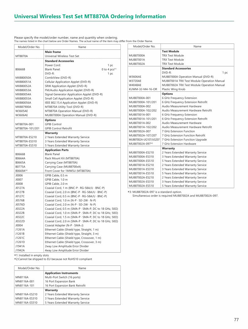
77
Please specify the model/order number, name and quantity when ordering.The names listed in the chart below are Order Names. The actual name of the item may differ from the Order Name.
Model/Order No. Name
MT8870AMain frameUniversal Wireless Test Set
B0666B
MX880050AMX880051AMX880052AMX880053AMX880054AMX880055AMX880056AMX887900AW3605AEW3606AE
Standard AccessoriesPower Cord: 1 pcBlank Panel: 0 to 4 pcs*1
DVD-R: 1 pcCombiView (DVD-R)Cellular Application Applet (DVD-R)SRW Application Applet (DVD-R)FM/Audio Application Applet (DVD-R)Signal Generator Application Applet (DVD-R)Small Cell Application Applet (DVD-R)IEEE 802.15.4 Application Applet (DVD-R)MT8870A Utility Tool (DVD-R)MT8870A Operation Manual (DVD-R)MU887000A Operation Manual (DVD-R)
MT8870A-001MT8870A-101/201
OptionsGPIB Control GPIB Control Retrofit
MT8870A-ES210MT8870A-ES310MT8870A-ES510
Warranty2 Years Extended Warranty Service3 Years Extended Warranty Service5 Years Extended Warranty Service
B0666BB0664A B0665AB0775AB0669A*2
Application PartsBlank PanelRack Mount Kit (MT8870A)Carrying Case (MT8870A)Carrying Case (MU88700xA) Front Cover for 1MW5U (MT8870A)
J0006J0007J0008J0127AJ0127BJ0127CJ0576BJ0576DJ0322AJ0322BJ0322CJ0322DJ0004J1261AJ1261BJ1261CJ1261DJ1941AJ1942A
GPIB Cable, 0.5 mGPIB Cable, 1.0 mGPIB Cable, 2.0 mCoaxial Cord, 1 m (BNC-P · RG-58A/U · BNC-P)Coaxial Cord, 2.0 m (BNC-P · RG-58A/U · BNC-P)Coaxial Cord, 0.5 m (BNC-P · RG-58A/U · BNC-P)Coaxial Cord, 1.0 m (N-P · 5D-2W · N-P)Coaxial Cord, 2.0 m (N-P · 5D-2W · N-P)Coaxial Cord, 0.5 m (SMA-P · SMA-P, DC to 18 GHz, 50Ω)Coaxial Cord, 1.0 m (SMA-P · SMA-P, DC to 18 GHz, 50Ω)Coaxial Cord, 1.5 m (SMA-P · SMA-P, DC to 18 GHz, 50Ω)Coaxial Cord, 2.0 m (SMA-P · SMA-P, DC to 18 GHz, 50Ω)Coaxial Adapter (N-P · SMA-J)Ethernet Cable (Shield type, Straight, 1 m)Ethernet Cable (Shield type, Straight, 3 m)Ethernet Cable (Shield type, Crossover, 1 m)Ethernet Cable (Shield type, Crossover, 3 m)2way Low Amplitude Error Divider4way Low Amplitude Error Divider
*1: Installed in empty slots *2:Cannot be shipped to EU because not RoHS10 compliant
Model/Order No. Name
MN8116AMN8116A-001MN8116A-101
Application InstrumentsMulti-Port Switch (16 ports)16 Port Expansion Bank16 Port Expansion Bank Retrofit
MN8116A-ES210MN8116A-ES310MN8116A-ES510
Warranty2 Years Extended Warranty Service3 Years Extended Warranty Service5 Years Extended Warranty Service
Model/Order No. Name
MU887000AMU887001AMU887002A
Test ModuleTRX Test ModuleTRX Test ModuleTRX Test Module
W3606AEW3720AEW4048AEKUWM-32-M4-16-OR
Standard AccessoriesDVD-R: 1 pcMU887000A Operation Manual (DVD-R)MU887001A TRX Test Module Operation ManualMU887002A TRX Test Module Operation ManualPlastic Wing Knob
MU887000A-001MU887000A-101/201MU887000A-002MU887000A-102/202MU887001A-001MU887001A-101/201MU887001A-002MU887001A-102/202MU887002A-007MU887002A-107/207MU887002A-UG107/UG207MU887002A-097*3
Options6 GHz Frequency Extension6 GHz Frequency Extension RetrofitAudio Measurement HardwareAudio Measurement Hardware Retrofit6 GHz Frequency Extension6 GHz Frequency Extension RetrofitAudio Measurement HardwareAudio Measurement Hardware Retrofit7 GHz Extension Function7 GHz Extension Function Retrofit7 GHz Extension Function Upgrade7 GHz Extension Hardware
MU887000A-ES210MU887000A-ES310MU887000A-ES510MU887001A-ES210MU887001A-ES310MU887001A-ES510MU887002A-ES210MU887002A-ES310MU887002A-ES510
Warranty2 Years Extended Warranty Service3 Years Extended Warranty Service5 Years Extended Warranty Service2 Years Extended Warranty Service3 Years Extended Warranty Service5 Years Extended Warranty Service2 Years Extended Warranty Service3 Years Extended Warranty Service5 Years Extended Warranty Service
*3: MU887002A-097 is a standard option. Simultaneous order is required MU887002A and MU887002A-097.
Universal Wireless Test Set MT8870A Ordering Information

78
Model/Order No. Name
MT8872AMain FrameUniversal Wireless Test Set
B0666A
MX880050AMX880051AMX880052AMX880053AMX880054AMX880055AMX880056AMX887900AW3605AEW3606AE
Standard AccessoriesPower Cord: 1 pcBlank Panel: 3 pcs*1
DVD-R: 1 pcCombiView (DVD-R)Cellular Application Applet (DVD-R)SRW Application Applet (DVD-R)FM/Audio Application Applet (DVD-R)Signal Generator Application Applet (DVD-R)Small Cell Application Applet (DVD-R)IEEE 802.15.4 Application Applet (DVD-R)MT8870A Utility Tool (DVD-R)MT8872A Operation Manual (DVD-R)MU887000A Operation Manual (DVD-R)
MT8872A-001MT8872A-101/201
OptionsGPIB Control GPIB Control Retrofit
MT8872A-ES210MT8872A-ES310MT8872A-ES510
Warranty2 Years Extended Warranty Service3 Years Extended Warranty Service5 Years Extended Warranty Service
B0666AB0774AB0775A
Application PartsBlank PanelCarrying Case (MT8872A)Carrying Case (MU88700xA)
J0006J0007J0008J0127AJ0127BJ0127CJ0576BJ0576DJ0322AJ0322BJ0322CJ0322DJ0004J1261AJ1261BJ1261CJ1261D
GPIB Cable, 0.5 mGPIB Cable, 1.0 mGPIB Cable, 2.0 mCoaxial Cord, 1 m (BNC-P · RG-58A/U · BNC-P)Coaxial Cord, 2.0 m (BNC-P · RG-58A/U · BNC-P)Coaxial Cord, 0.5 m (BNC-P · RG-58A/U · BNC-P)Coaxial Cord, 1.0 m (N-P · 5D-2W · N-P)Coaxial Cord, 2.0 m (N-P · 5D-2W · N-P)Coaxial Cord, 0.5 m (SMA-P · SMA-P, DC to 18 GHz, 50Ω)Coaxial Cord, 1.0 m (SMA-P · SMA-P, DC to 18 GHz, 50Ω)Coaxial Cord, 1.5 m (SMA-P · SMA-P, DC to 18 GHz, 50Ω)Coaxial Cord, 2.0 m (SMA-P · SMA-P, DC to 18 GHz, 50Ω)Coaxial Adapter (N-P · SMA-J)Ethernet Cable (Shield type, Straight, 1 m)Ethernet Cable (Shield type, Straight, 3 m)Ethernet Cable (Shield type, Crossover, 1 m)Ethernet Cable (Shield type, Crossover, 3 m)
*1: Installed in empty slots
Model/Order No. Name
MU887000AMU887001AMU887002A
Test ModuleTRX Test ModuleTRX Test ModuleTRX Test Module
W3606AEW3720AEW4048AEKUWM-32-M4-16-OR
Standard AccessoriesDVD-R: 1 pcMU887000A Operation Manual (DVD-R)MU887001A TRX Test Module Operation ManualMU887002A TRX Test Module Operation ManualPlastic Wing Knob
MU887000A-001MU887000A-101/201MU887000A-002MU887000A-102/202MU887001A-001MU887001A-101/201MU887001A-002MU887001A-102/202MU887002A-007MU887002A-107/207MU887002A-UG107/UG207MU887002A-097*2
Options6 GHz Frequency Extension6 GHz Frequency Extension RetrofitAudio Measurement HardwareAudio Measurement Hardware Retrofit6 GHz Frequency Extension6 GHz Frequency Extension RetrofitAudio Measurement HardwareAudio Measurement Hardware Retrofit7 GHz Extension Function7 GHz Extension Function Retrofit7 GHz Extension Function Upgrade7 GHz Extension Hardware
MU887000A-ES210MU887000A-ES310MU887000A-ES510MU887001A-ES210MU887001A-ES310MU887001A-ES510MU887002A-ES210MU887002A-ES310MU887002A-ES510
Warranty2 Years Extended Warranty Service3 Years Extended Warranty Service5 Years Extended Warranty Service2 Years Extended Warranty Service3 Years Extended Warranty Service5 Years Extended Warranty Service2 Years Extended Warranty Service3 Years Extended Warranty Service5 Years Extended Warranty Service
*2: MU887002A-097 is a standard option. Simultaneous order is required MU887002A and MU887002A-097.
Universal Wireless Test Set MT8872A Ordering Information
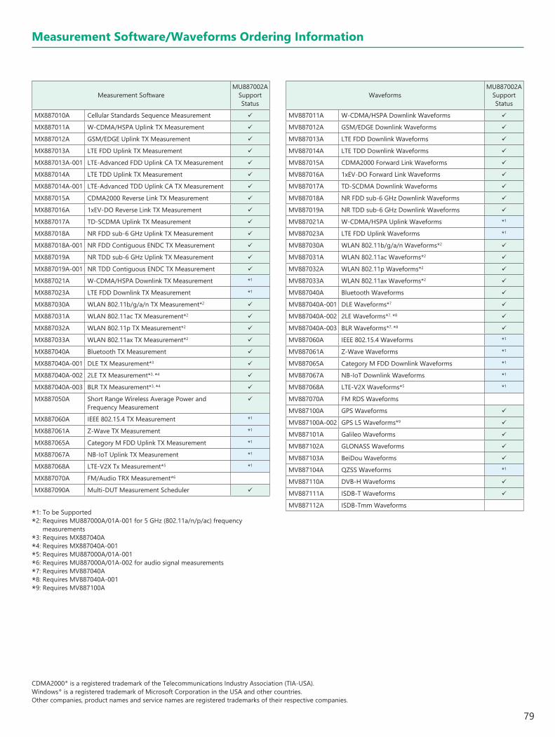
79
Measurement Software/Waveforms Ordering Information
CDMA2000® is a registered trademark of the Telecommunications Industry Association (TIA-USA).Windows® is a registered trademark of Microsoft Corporation in the USA and other countries.Other companies, product names and service names are registered trademarks of their respective companies.
Measurement SoftwareMU887002A
Support Status
MX887010A Cellular Standards Sequence Measurement
MX887011A W-CDMA/HSPA Uplink TX Measurement
MX887012A GSM/EDGE Uplink TX Measurement
MX887013A LTE FDD Uplink TX Measurement
MX887013A-001 LTE-Advanced FDD Uplink CA TX Measurement
MX887014A LTE TDD Uplink TX Measurement
MX887014A-001 LTE-Advanced TDD Uplink CA TX Measurement
MX887015A CDMA2000 Reverse Link TX Measurement
MX887016A 1xEV-DO Reverse Link TX Measurement
MX887017A TD-SCDMA Uplink TX Measurement
MX887018A NR FDD sub-6 GHz Uplink TX Measurement
MX887018A-001 NR FDD Contiguous ENDC TX Measurement
MX887019A NR TDD sub-6 GHz Uplink TX Measurement
MX887019A-001 NR TDD Contiguous ENDC TX Measurement
MX887021A W-CDMA/HSPA Downlink TX Measurement *1
MX887023A LTE FDD Downlink TX Measurement *1
MX887030A WLAN 802.11b/g/a/n TX Measurement*2
MX887031A WLAN 802.11ac TX Measurement*2
MX887032A WLAN 802.11p TX Measurement*2
MX887033A WLAN 802.11ax TX Measurement*2
MX887040A Bluetooth TX Measurement
MX887040A-001 DLE TX Measurement*3
MX887040A-002 2LE TX Measurement*3, *4
MX887040A-003 BLR TX Measurement*3, *4
MX887050A Short Range Wireless Average Power and Frequency Measurement
MX887060A IEEE 802.15.4 TX Measurement *1
MX887061A Z-Wave TX Measurement *1
MX887065A Category M FDD Uplink TX Measurement *1
MX887067A NB-IoT Uplink TX Measurement *1
MX887068A LTE-V2X Tx Measurement*5 *1
MX887070A FM/Audio TRX Measurement*6
MX887090A Multi-DUT Measurement Scheduler
*1: To be Supported*2: Requires MU887000A/01A-001 for 5 GHz (802.11a/n/p/ac) frequency
measurements*3: Requires MX887040A*4: Requires MX887040A-001*5: Requires MU887000A/01A-001*6: Requires MU887000A/01A-002 for audio signal measurements*7: Requires MV887040A*8: Requires MV887040A-001*9: Requires MV887100A
WaveformsMU887002A
Support Status
MV887011A W-CDMA/HSPA Downlink Waveforms
MV887012A GSM/EDGE Downlink Waveforms
MV887013A LTE FDD Downlink Waveforms
MV887014A LTE TDD Downlink Waveforms
MV887015A CDMA2000 Forward Link Waveforms
MV887016A 1xEV-DO Forward Link Waveforms
MV887017A TD-SCDMA Downlink Waveforms
MV887018A NR FDD sub-6 GHz Downlink Waveforms
MV887019A NR TDD sub-6 GHz Downlink Waveforms
MV887021A W-CDMA/HSPA Uplink Waveforms *1
MV887023A LTE FDD Uplink Waveforms *1
MV887030A WLAN 802.11b/g/a/n Waveforms*2
MV887031A WLAN 802.11ac Waveforms*2
MV887032A WLAN 802.11p Waveforms*2
MV887033A WLAN 802.11ax Waveforms*2
MV887040A Bluetooth Waveforms
MV887040A-001 DLE Waveforms*7
MV887040A-002 2LE Waveforms*7, *8
MV887040A-003 BLR Waveforms*7, *8
MV887060A IEEE 802.15.4 Waveforms *1
MV887061A Z-Wave Waveforms *1
MV887065A Category M FDD Downlink Waveforms *1
MV887067A NB-IoT Downlink Waveforms *1
MV887068A LTE-V2X Waveforms*5 *1
MV887070A FM RDS Waveforms
MV887100A GPS Waveforms
MV887100A-002 GPS L5 Waveforms*9
MV887101A Galileo Waveforms
MV887102A GLONASS Waveforms
MV887103A BeiDou Waveforms
MV887104A QZSS Waveforms *1
MV887110A DVB-H Waveforms
MV887111A ISDB-T Waveforms
MV887112A ISDB-Tmm Waveforms

Anritsu Americas Sales Company 450 Century Parkway, Suite 190, Allen, TX 75013 U.S.A.Phone: +1-800-Anritsu (1-800-267-4878)
• CanadaAnritsu Electronics Ltd.700 Silver Seven Road, Suite 120, Kanata, Ontario K2V 1C3, CanadaPhone: +1-613-591-2003 Fax: +1-613-591-1006
• Brazil Anritsu Eletronica Ltda.
• MexicoAnritsu Company, S.A. de C.V.Blvd Miguel de Cervantes Saavedra #169 Piso 1, Col. GranadaMexico, Ciudad de Mexico, 11520, MEXICOPhone: +52-55-4169-7104
• United KingdomAnritsu EMEA Ltd. 200 Capability Green, Luton, Bedfordshire, LU1 3LU, U.K.Phone: +44-1582-433200 Fax: +44-1582-731303
• FranceAnritsu S.A. 12 avenue du Québec, Immeuble Goyave,91140 VILLEBON SUR YVETTE, FrancePhone: +33-1-60-92-15-50
• GermanyAnritsu GmbHNemetschek Haus, Konrad-Zuse-Platz 1, 81829 München, Germany Phone: +49-89-442308-0Fax: +49-89-442308-55
• ItalyAnritsu S.r.l.Spaces Eur Arte, Viale dell’Arte 25, 00144 Roma, ItalyPhone: +39-6-509-9711
• SwedenAnritsu ABKistagången 20 B, 2 tr, 164 40 Kista, SwedenPhone: +46-8-534-707-00
• FinlandAnritsu ABTechnopolis Aviapolis, Teknobulevardi 3-5 (D208.5.),FI-01530 Vantaa, FinlandPhone: +358-20-741-8100
• DenmarkAnritsu A/Sc/o Regus Winghouse, Ørestads Boulevard 73, 4th floor, 2300 Copenhagen S, DenmarkPhone: +45-7211-2200
• RussiaAnritsu EMEA Ltd. Representation Office in RussiaTverskaya str. 16/2, bld. 1, 7th floor., Moscow, 125009, RussiaPhone: +7-495-363-1694Fax: +7-495-935-8962
• SpainAnritsu EMEA Ltd.Representation Office in SpainPaseo de la Castellana, 141. Planta 5, Edificio Cuzco IV28046, Madrid, SpainPhone: +34-91-572-6761
• AustriaAnritsu EMEA GmbHAm Belvedere 10, A-1100 Vienna, AustriaPhone: +43-(0)1-717-28-710
• United Arab EmiratesAnritsu EMEA Ltd.
Anritsu A/S
2106
• SingaporeAnritsu Pte. Ltd.11 Chang Charn Road, #04-01, Shriro House, Singapore 159640Phone: +65-6282-2400Fax: +65-6282-2533
• VietnamAnritsu Company Limited16th Floor, Peakview Tower, 36 Hoang Cau Street, O Cho Dua Ward, Dong Da District, Hanoi, VietnamPhone: +84-24-3201-2730
• IndiaAnritsu India Private Limited6th Floor, Indiqube ETA, No.38/4, Adjacent to EMC2,Doddanekundi, Outer Ring Road, Bengaluru – 560048, IndiaPhone: +91-80-6728-1300Fax: +91-80-6728-1301
Specifications are subject to change without notice.
• United States
• P.R. China (Shanghai)Anritsu (China) Co., Ltd.Room 2701-2705, Tower A, New Caohejing International Business Center No. 391 Gui Ping Road Shanghai, 200233, P.R. ChinaPhone: +86-21-6237-0898Fax: +86-21-6237-0899
• P.R. China (Hong Kong)Anritsu Company Ltd.Unit 1006-7, 10/F., Greenfield Tower, Concordia Plaza,No. 1 Science Museum Road, Tsim Sha Tsui East, Kowloon, Hong Kong, P.R. ChinaPhone: +852-2301-4980Fax: +852-2301-3545
• JapanAnritsu Corporation8-5, Tamura-cho, Atsugi-shi, Kanagawa, 243-0016 JapanPhone: +81-46-296-6509Fax: +81-46-225-8352
• KoreaAnritsu Corporation, Ltd.5FL, 235 Pangyoyeok-ro, Bundang-gu, Seongnam-si, Gyeonggi-do, 13494 KoreaPhone: +82-31-696-7750Fax: +82-31-696-7751
• AustraliaAnritsu Pty. Ltd.
• TaiwanAnritsu Company Inc.7F, No. 316, Sec. 1, NeiHu Rd., Taipei 114, TaiwanPhone: +886-2-8751-1816Fax: +886-2-8751-1817
Unit 20, 21-35 Ricketts Road, Mount Waverley, Victoria 3149, AustraliaPhone: +61-3-9558-8177Fax: +61-3-9558-8255
Office No. 164, Building 17, Dubai Internet CityP. O. Box – 501901, Dubai, United Arab EmiratesPhone: +971-4-3758479
Praça Amadeu Amaral, 27 - 1 Andar01327-010 - Bela Vista - Sao Paulo - SP, BrazilPhone: +55-11-3283-2511Fax: +55-11-3288-6940
Printed in Japan 16/SEP/2021 ddcm/CDT Catalog No. MT8870A_72A-E-A-1-(5.00)


