AVERTISSEMENTUNE PORTE EN MOUVEMENT PEUT CAUSER DE GRAVES
BLESSURES, VOIRE LA MORT.•N’installez PAS le transmetteur à moins que l’appareil de sécurité du dispositif de fermeture de porte ne fonctionne conformément au manuel du dispositif de fermeture de porte. •La console murale doit être montée à la vue de la porte, à au moins 5 pieds au-dessus du sol et il ne doit y avoir aucune pièce de porte en mouvement à proximité. •Éloignez les gens de l’ouverture lorsque la porte est en mouvement.•NE permettez PAS aux enfants de jouer avec le transmetteur ou le dispositif de fermeture de porte.
Si l’inversion de sécurité ne fonctionne pas correctement : •Fermez la porte, puis déconnectez le dispositif d’ouverture à l’aide de la poignée de dégagement manuel. •N’utilisez PAS le transmetteur ni le dispositif de fermeture de porte.•Référez-vous aux manuels du propriétaire de la porte et de l’ouvre-porte avant de tenter toute réparation.
!
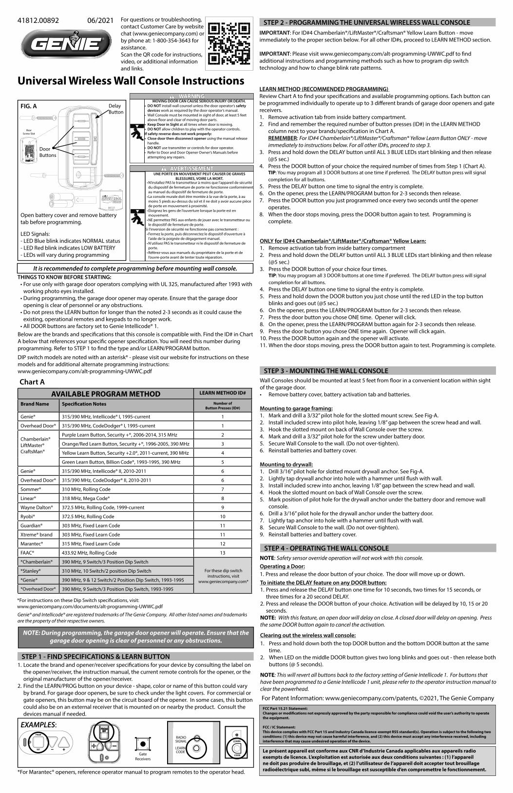
FIG. A
For questions or troubleshooting, contact Customer Care by website chat (www.geniecompany.com) or by phone at: 1-800-354-3643 for assistance.Scan the QR code for instructions, video, or additional information and links.
Open battery cover and remove battery tab before programming.
LED Signals:- LED Blue blink indicates NORMAL status- LED Red blink indicates LOW BATTERY- LEDs will vary during programming
It is recommended to complete programming before mounting wall console.
NOTE: During programming, the garage door opener will operate. Ensure that the garage door opening is clear of personnel or any obstructions.
Chart A
Genie® and Intellicode® are registered trademarks of The Genie Company. All other listed names and trademarks are the property of their respective owners.
THINGS TO KNOW BEFORE STARTING:•For use only with garage door operators complying with UL 325, manufactured after 1993 with
working photo eyes installed.•During programming, the garage door opener may operate. Ensure that the garage door
opening is clear of personnel or any obstructions.•Do not press the LEARN button for longer than the noted 2-3 seconds as it could cause the
existing, operational remotes and keypads to no longer work.•All DOOR buttons are factory set to Genie Intellicode® 1.
DIP switch models are noted with an asterisk* - please visit our website for instructions on these models and for additional alternate programming instructions:www.geniecompany.com/alt-programming-UWWC.pdf
Below are the brands and specifications that this console is compatible with. Find the ID# in Chart A below that references your specific opener specification. You will need this number during programming. Refer to STEP 1 to find the type and/or LEARN/PROGRAM button.
STEP 1 - FIND SPECIFICATIONS & LEARN BUTTON1. Locate the brand and opener/receiver specifications for your device by consulting the label on
the opener/receiver, the instruction manual, the current remote controls for the opener, or the original manufacturer of the opener/receiver.
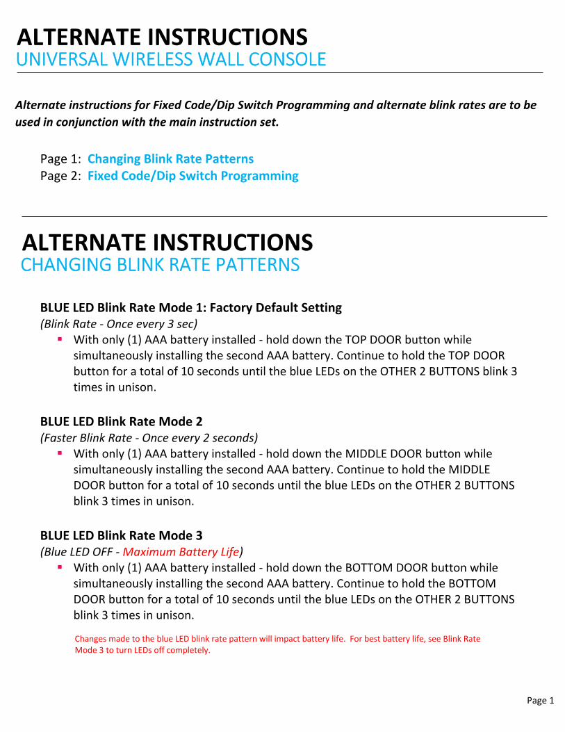
2. Find the LEARN/PROG button on your device - shape, color or name of this button could vary by brand. For garage door openers, be sure to check under the light covers. For commercial or gate openers, this button may be on the circuit board of the opener. In some cases, this button could also be on an external receiver that is mounted on or nearby the product. Consult the devices manual if needed.
PRGM
SET
RADIOSIGNAL
LEARNCODE
CODE
LEARN
GateReceivers
EXAMPLES:
*For Marantec® openers, reference operator manual to program remotes to the operator head.
STEP 2 - PROGRAMMING THE UNIVERSAL WIRELESS WALL CONSOLEIMPORTANT: For ID#4 Chamberlain®/LiftMaster®/Craftsman® Yellow Learn Button - move immediately to the proper section below. For all other ID#s, proceed to LEARN METHOD section.
IMPORTANT: Please visit www.geniecompany.com/alt-programming-UWWC.pdf to find additional instructions and programming methods such as how to program dip switch technology and how to change blink rate patterns.
LEARN METHOD (RECOMMENDED PROGRAMMING) Review Chart A to find your specifications and available programming options. Each button can be programmed individually to operate up to 3 different brands of garage door openers and gate receivers. 1. Remove activation tab from inside battery compartment.2. Find and remember the required number of button presses (ID#) in the LEARN METHOD
column next to your brands/specification in Chart A.REMEMBER: For ID#4 Chamberlain®/LiftMaster®/Craftsman® Yellow Learn Button ONLY - move immediately to instructions below. For all other ID#s, proceed to step 3.
3. Press and hold down the DELAY button until ALL 3 BLUE LEDs start blinking and then release (@5 sec.)
4. Press the DOOR button of your choice the required number of times from Step 1 (Chart A).TIP: You may program all 3 DOOR buttons at one time if preferred. The DELAY button press will signal completion for all buttons.
5. Press the DELAY button one time to signal the entry is complete.6. On the opener, press the LEARN/PROGRAM button for 2-3 seconds then release.7. Press the DOOR button you just programmed once every two seconds until the opener
operates.8. When the door stops moving, press the DOOR button again to test. Programming is
complete.
ONLY for ID#4 Chamberlain®/LiftMaster®/Craftsman® Yellow Learn:1. Remove activation tab from inside battery compartment2. Press and hold down the DELAY button until ALL 3 BLUE LEDs start blinking and then release
(@5 sec.)3. Press the DOOR button of your choice four times.
TIP: You may program all 3 DOOR buttons at one time if preferred. The DELAY button press will signal completion for all buttons.
4. Press the DELAY button one time to signal the entry is complete.5. Press and hold down the DOOR button you just chose until the red LED in the top button
blinks and goes out (@5 sec.)6. On the opener, press the LEARN/PROGRAM button for 2-3 seconds then release.7. Press the door button you chose ONE time. Opener will click.8. On the opener, press the LEARN/PROGRAM button again for 2-3 seconds then release.9. Press the door button you chose ONE time again. Opener will click again.10. Press the DOOR button again and the opener will activate.11. When the door stops moving, press the DOOR button again to test. Programming is complete.
FCC Part 15.21 Statement: Changes or modifications not expressly approved by the party responsible for compliance could void the user’s authority to operate the equipment. FCC / IC Statement: This device complies with FCC Part 15 and Industry Canada licence-exempt RSS standard(s). Operation is subject to the following two conditions: (1) this device may not cause harmful interference, and (2) this device must accept any interference received, including interference that may cause undesired operation of the device.
Wall Consoles should be mounted at least 5 feet from floor in a convenient location within sight of the garage door.• Remove battery cover, battery activation tab and batteries.
Mounting to garage framing:1. Mark and drill a 3/32” pilot hole for the slotted mount screw. See Fig-A.2. Install included screw into pilot hole, leaving 1/8” gap between the screw head and wall.3. Hook the slotted mount on back of Wall Console over the screw.4. Mark and drill a 3/32” pilot hole for the screw under battery door.5. Secure Wall Console to the wall. (Do not over-tighten).6. Reinstall batteries and battery cover.
Mounting to drywall:1. Drill 3/16” pilot hole for slotted mount drywall anchor. See Fig-A.2. Lightly tap drywall anchor into hole with a hammer until flush with wall.3. Install included screw into anchor, leaving 1/8” gap between the screw head and wall.4. Hook the slotted mount on back of Wall Console over the screw.5. Mark position of pilot hole for the drywall anchor under the battery door and remove wall
console.6. Drill a 3/16” pilot hole for the drywall anchor under the battery door.7. Lightly tap anchor into hole with a hammer until flush with wall.8. Secure Wall Console to the wall. (Do not over-tighten).9. Reinstall batteries and battery cover.
Clearing out the wireless wall console:1. Press and hold down both the top DOOR button and the bottom DOOR button at the same
time.2. When LED on the middle DOOR button gives two long blinks and goes out - then release both
buttons (@ 5 seconds).
To initiate the DELAY feature on any DOOR button:1. Press and release the DELAY button one time for 10 seconds, two times for 15 seconds, or
three times for a 20 second DELAY.2. Press and release the DOOR button of your choice. Activation will be delayed by 10, 15 or 20
seconds.NOTE: With this feature, an open door will delay on close. A closed door will delay on opening. Press the same DOOR button again to cancel the activation.
STEP 4 - OPERATING THE WALL CONSOLENOTE: Safety sensor override operation will not work with this console.Operating a Door:1. Press and release the door button of your choice. The door will move up or down.
MOVING DOOR CAN CAUSE SERIOUS INJURY OR DEATH.• DO NOT install wall counsel unless the door operator’s safety
devices work as required by the door operator’s manual.• Wall Console must be mounted in sight of door, at least 5 feet
above floor and clear of moving door parts.• Keep Door in Sight at all times when door is moving.• DO NOT allow children to play with the operator controls.If safety reverse does not work properly:• Close door then disconnect opener using the manual release
handle.• DO NOT use transmitter or controls for door operator.• Refer to Door and Door Opener Owner’s Manuals before
attempting any repairs.
NOTE: This will revert all buttons back to the factory setting of Genie Intellicode 1. For buttons that have been programmed to a Genie Intellicode 1 unit, please refer to the operator instruction manual to clear the powerhead.
Le présent appareil est conforme aux CNR d’Industrie Canada applicables aux appareils radio exempts de licence. L’exploitation est autorisée aux deux conditions suivantes : (1) l’appareil ne doit pas produire de brouillage, et (2) l’utilisateur de l’appareil doit accepter tout brouillage radioélectrique subi, même si le brouillage est susceptible d’en compromettre le fonctionnement.
AVAILABLE PROGRAM METHOD LEARN METHOD ID#
Brand Name Specification Notes Number of Button Presses (ID#)
Genie® 315/390 MHz, Intellicode® I, 1995-current 1
Overhead Door® 315/390 MHz, CodeDodger® I, 1995-current 1
Alternate instructions for Fixed Code/Dip Switch Programming and alternate blink rates are to be
used in conjunction with the main instruction set.
Changes made to the blue LED blink rate pattern will impact battery life. For best battery life, see Blink Rate Mode 3 to turn LEDs off completely.
BLUE LED Blink Rate Mode 1: Factory Default Setting (Blink Rate ‐ Once every 3 sec) With only (1) AAA battery installed ‐ hold down the TOP DOOR button while
simultaneously installing the second AAA battery. Continue to hold the TOP DOOR button for a total of 10 seconds until the blue LEDs on the OTHER 2 BUTTONS blink 3 times in unison.
BLUE LED Blink Rate Mode 2 (Faster Blink Rate ‐ Once every 2 seconds) With only (1) AAA battery installed ‐ hold down the MIDDLE DOOR button while
simultaneously installing the second AAA battery. Continue to hold the MIDDLE DOOR button for a total of 10 seconds until the blue LEDs on the OTHER 2 BUTTONS blink 3 times in unison.
BLUE LED Blink Rate Mode 3 (Blue LED OFF ‐ Maximum Battery Life) With only (1) AAA battery installed ‐ hold down the BOTTOM DOOR button while
simultaneously installing the second AAA battery. Continue to hold the BOTTOM DOOR button for a total of 10 seconds until the blue LEDs on the OTHER 2 BUTTONS blink 3 times in unison.
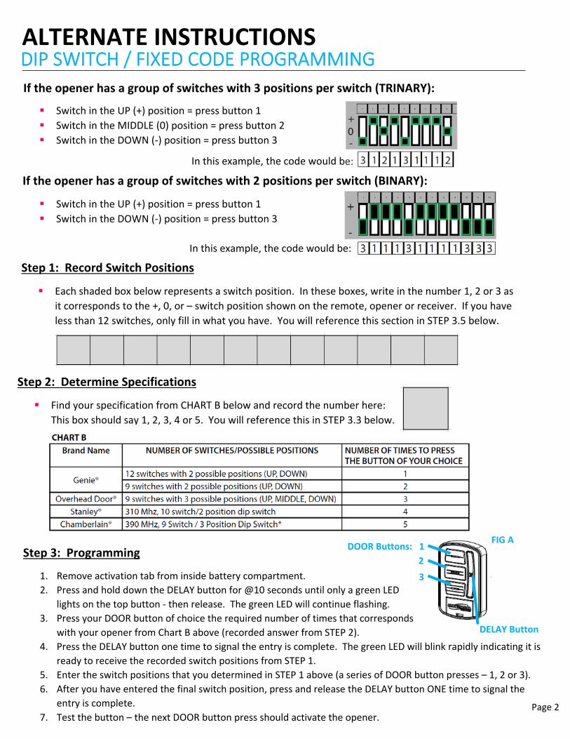
If the opener has a group of switches with 3 positions per switch (TRINARY):
Switch in the UP (+) position = press button 1
Switch in the MIDDLE (0) position = press button 2
Switch in the DOWN (‐) position = press button 3
In this example, the code would be:
If the opener has a group of switches with 2 positions per switch (BINARY):
Switch in the UP (+) position = press button 1
Switch in the DOWN (‐) position = press button 3
In this example, the code would be:
Step 1: Record Switch Positions
Each shaded box below represents a switch position. In these boxes, write in the number 1, 2 or 3 as
it corresponds to the +, 0, or – switch position shown on the remote, opener or receiver. If you have
less than 12 switches, only fill in what you have. You will reference this section in STEP 3.5 below.
Step 2: Determine Specifications
Find your specification from CHART B below and record the number here:
This box should say 1, 2, 3, 4 or 5. You will reference this in STEP 3.3 below.
Step 3: Programming
1. Remove activation tab from inside battery compartment.
2. Press and hold down the DELAY button for @10 seconds until only a green LED
lights on the top button ‐ then release. The green LED will continue flashing.
3. Press your DOOR button of choice the required number of times that corresponds
with your opener from Chart B above (recorded answer from STEP 2).
4. Press the DELAY button one time to signal the entry is complete. The green LED will blink rapidly indicating it is
ready to receive the recorded switch positions from STEP 1.
5. Enter the switch positions that you determined in STEP 1 above (a series of DOOR button presses – 1, 2 or 3).
6. After you have entered the final switch position, press and release the DELAY button ONE time to signal the
entry is complete.
7. Test the button – the next DOOR button press should activate the opener.
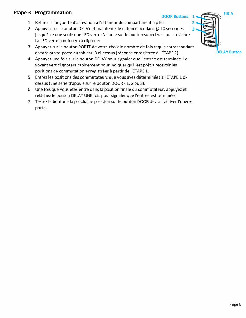
DOOR Buttons: 1
2
3
DELAY Button
FIG A
CONSOLA DE PARED INALÁMBRICA UNIVERSAL
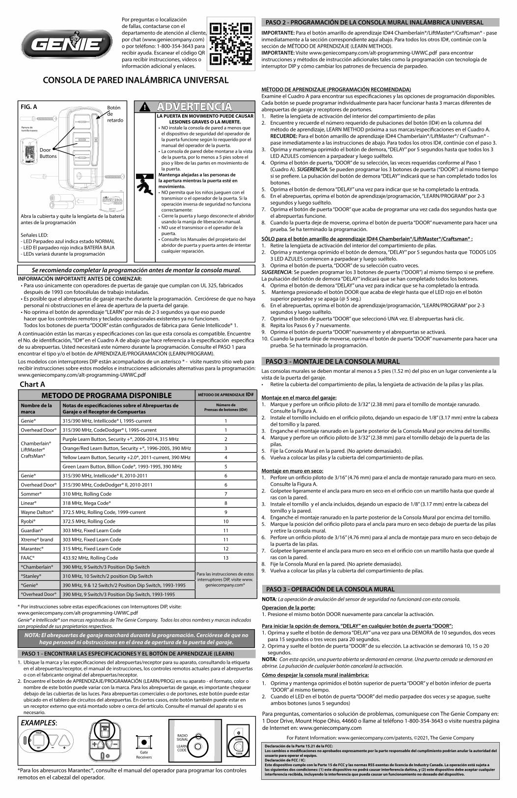
FIG. A
Por preguntas o localización de fallas, contactarse con el departamento de atención al cliente, por chat (www.geniecompany.com) o por teléfono: 1-800-354-3643 para recibir ayuda. Escanear el código QR para recibir instrucciones, videos o información adicional y enlaces.
Abra la cubierta y quite la lengüeta de la batería antes de la programación
Señales LED:- LED Parpadeo azul indica estado NORMAL- LED El parpadeo rojo indica BATERÍA BAJA- LEDs variará durante la programación
Se recomienda completar la programación antes de montar la consola mural.
NOTA: El abrepuertas de garaje marchará durante la programación. Cerciórese de que no haya personal ni obstrucciones en el área de apertura de la puerta del garaje.
Chart A
Genie® e Intellicode® son marcas registradas de The Genie Company. Todos los otros nombres y marcas indicados son propiedad de sus propietarios respectivos.
* Por instrucciones sobre estas especificaciones con Interruptores DIP, visite:www.geniecompany.com/alt-programming-UWWC.pdf
INFORMACIÓN IMPORTANTE ANTES DE COMENZAR:•Para uso únicamente con operadores de puertas de garaje que cumplan con UL 325, fabricados
después de 1993 con fotocélulas de trabajo instaladas.•Es posible que el abrepuertas de garaje marche durante la programación. Cerciórese de que no haya
personal ni obstrucciones en el área de apertura de la puerta del garaje.•No oprima el botón de aprendizaje “LEARN” por más de 2-3 segundos ya que eso puede
hacer que los controles remotos y teclados operacionales existentes ya no funcionen. Todos los botones de puerta “DOOR” están configurados de fábrica para Genie Intellicode® 1.
Los modelos con interruptores DIP están acompañados de un asterisco * - visite nuestro sitio web para recibir instrucciones sobre estos modelos e instrucciones adicionales alternativas para la programación: www.geniecompany.com/alt-programming-UWWC.pdf
A continuación están las marcas y especificaciones con las que esta consola es compatible. Encuentre el No. de identificación, “ID#” en el Cuadro A de abajo que hace referencia a la especificación específica de su abrepuertas. Usted necesitará este número durante la programación. Consulte el PASO 1 para encontrar el tipo y/o el botón de APRENDIZAJE/PROGRAMACIÓN (LEARN/PROGRAM).
PASO 1 - ENCONTRAR LAS ESPECIFICACIONES Y EL BOTÓN DE APRENDIZAJE (LEARN)1. Ubique la marca y las especificaciones del abrepuertas/receptor para su aparato, consultando la etiqueta
en el abrepuertas/receptor, el manual de instrucciones, los controles remotos actuales para el abrepuertas o con el fabricante original del abrepuertas/receptor.
2. Encuentre el botón de APRENDIZAJE/PROGRAMACIÓN (LEARN/PROG) en su aparato - el formato, color o nombre de este botón puede variar con la marca. Para los abrepuertas de garaje, es importante chequear debajo de las cubiertas de las luces. Para abrepuertas comerciales o de portones, este botón puede estar ubicado en el tablero de circuitos del abrepuertas. En ciertos casos, este botón también puede estar en un receptor externo que está montado sobre o cerca del artículo. Consulte el manual del aparato si es necesario.
PRGM
SET
RADIOSIGNAL
LEARNCODE
CODE
LEARN
GateReceivers
EXAMPLES:
*Para los abresurcos Marantec®, consulte el manual del operador para programar los controles remotos en el cabezal del operador.
PASO 2 - PROGRAMACIÓN DE LA CONSOLA MURAL INALÁMBRICA UNIVERSAL
IMPORTANTE: Para el botón amarillo de aprendizaje ID#4 Chamberlain®/LiftMaster®/Craftsman® - pase inmediatamente a la sección correspondiente aquí abajo. Para todos los otros ID#, continúe con la sección de MÉTODO DE APRENDIZAJE (LEARN METHOD).IMPORTANTE: Visite www.geniecompany.com/alt-programming-UWWC.pdf para encontrar instrucciones y métodos de instrucción adicionales tales como la programación con tecnología de interruptor DIP y cómo cambiar los patrones de frecuencia de parpadeo.
MÉTODO DE APRENDIZAJE (PROGRAMACIÓN RECOMENDADA)Examine el Cuadro A para encontrar sus especificaciones y las opciones de programación disponibles. Cada botón se puede programar individualmente para hacer funcionar hasta 3 marcas diferentes de abrepuertas de garaje y receptores de portones. 1. Retire la lengüeta de activación del interior del compartimiento de pilas2. Encuentre y recuerde el número requerido de pulsaciones del botón (ID#) en la columna del
método de aprendizaje, LEARN METHOD próxima a sus marcas/especificaciones en el Cuadro A. RECUERDE: Para el botón amarillo de aprendizaje ID#4 Chamberlain®/LiftMaster®/ Craftsman® - pase inmediatamente a las instrucciones de abajo. Para todos los otros ID#, continúe con el paso 3.
3. Oprima y mantenga oprimido el botón de demora, “DELAY” por 5 segundos hasta que todos los 3 LED AZULES comiencen a parpadear y luego suéltelo.
4. Oprima el botón de puerta, “DOOR” de su selección, las veces requeridas conforme al Paso 1 (Cuadro A). SUGERENCIA: Se pueden programar los 3 botones de puerta (“DOOR”) al mismo tiempo si se prefiere. La pulsación del botón de demora “DELAY” indicará que se han completado todos los botones.
5. Oprima el botón de demora “DELAY” una vez para indicar que se ha completado la entrada.6. En el abrepuertas, oprima el botón de aprendizaje/programación, “LEARN/PROGRAM” por 2-3
segundos y luego suéltelo.7. Oprima el botón de puerta “DOOR” que acaba de programar una vez cada dos segundos hasta que
el abrepuertas funcione.8. Cuando la puerta deje de moverse, oprima el botón de puerta “DOOR” nuevamente para hacer una
prueba. Se ha terminado la programación.
SÓLO para el botón amarillo de aprendizaje ID#4 Chamberlain®/LiftMaster®/Craftsman® :1. Retire la lengüeta de activación del interior del compartimiento de pilas.2. Oprima y mantenga oprimido el botón de demora, “DELAY” por 5 segundos hasta que TODOS LOS
3 LED AZULES comiencen a parpadear y luego suéltelo.3. Oprima el botón de puerta, “DOOR” de su selección cuatro veces.SUGERENCIA: Se pueden programar los 3 botones de puerta (“DOOR”) al mismo tiempo si se prefiere. La pulsación del botón de demora “DELAY” indicará que se han completado todos los botones. 4. Oprima el botón de demora “DELAY” una vez para indicar que se ha completado la entrada.5. Mantenga presionado el botón DOOR que acaba de elegir hasta que el LED rojo en el botón
superior parpadee y se apaga (@ 5 seg.)6. En el abrepuertas, oprima el botón de aprendizaje/programación, “LEARN/PROGRAM” por 2-3
segundos y luego suéltelo.7. Oprima el botón de puerta “DOOR” que seleccionó UNA vez. El abrepuertas hará clic.8. Repita los Pasos 6 y 7 nuevamente.9. Oprima el botón de puerta “DOOR” nuevamente y el abrepuertas se activará. 10. Cuando la puerta deje de moverse, oprima el botón de puerta “DOOR” nuevamente para hacer una
prueba. Se ha terminado la programación.
Las consolas murales se deben montar al menos a 5 pies (1.52 m) del piso en un lugar conveniente a la vista de la puerta del garaje.• Retire la cubierta del compartimiento de pilas, la lengüeta de activación de la pilas y las pilas.
Montaje en el marco del garaje:1. Marque y perfore un orificio piloto de 3/32” (2.38 mm) para el tornillo de montaje ranurado.
Consulte la Figura A. 2. Instale el tornillo incluido en el orificio piloto, dejando un espacio de 1/8” (3.17 mm) entre la cabeza
del tornillo y la pared.3. Enganche el montaje ranurado en la parte posterior de la Consola Mural por encima del tornillo. 4. Marque y perfore un orificio piloto de 3/32” (2.38 mm) para el tornillo debajo de la puerta de las
pilas.5. Fije la Consola Mural en la pared. (No apriete demasiado).6. Vuelva a colocar las pilas y la cubierta del compartimiento de pilas.
Montaje en muro en seco:1. Perfore un orificio piloto de 3/16” (4.76 mm) para el ancla de montaje ranurado para muro en seco.
Consulte la Figura A.2. Golpetee ligeramente el ancla para muro en seco en el orificio con un martillo hasta que quede al
ras con la pared.3. Instale el tornillo y el ancla incluidos, dejando un espacio de 1/8” (3.17 mm) entre la cabeza del
tornillo y la pared. 4. Enganche el montaje ranurado en la parte posterior de la Consola Mural por encima del tornillo.5. Marque la posición del orificio piloto para el ancla para muro en seco debajo de puerta de las pilas
y retire la consola mural.6. Perfore un orificio piloto de 3/16” (4.76 mm) para al ancla de montaje para muro en seco debajo de
la puerta de las pilas.7. Golpetee ligeramente el ancla para muro en seco en el orificio con un martillo hasta que quede al
ras con la pared.8. Fije la Consola Mural en la pared. (No apriete demasiado).9. Vuelva a colocar las pilas y la cubierta del compartimiento de pilas.
PASO 3 - MONTAJE DE LA CONSOLA MURAL
RearScrew Slot
Botón de retardo
Door Buttons
Cómo despejar la consola mural inalámbrica:1. Oprima y mantenga oprimidos el botón superior de puerta “DOOR” y el botón inferior de puerta
“DOOR” al mismo tiempo. 2. Cuando el LED en el botón de puerta “DOOR” del medio parpadee dos veces y se apague, suelte
ambos botones (unos 5 segundos)
Para iniciar la opción de demora, “DELAY” en cualquier botón de puerta “DOOR”:1. Oprima y suelte el botón de demora “DELAY” una vez para una DEMORA de 10 segundos, dos veces
para 15 segundos o tres veces para 20 segundos.2. Oprima y suelte el botón de puerta “DOOR” de su elección. La activación se demorará 10, 15 o 20
segundos.NOTA: Con esta opción, una puerta abierta se demorará en cerrarse. Una puerta cerrada se demorará en abrirse. La pulsación de cualquier botón cancelará la activación.
PASO 3 - OPERACIÓN DE LA CONSOLA MURALNOTA: La operación de anulación del sensor de seguridad no funcionará con esta consola.
Operacion de la porte:1. Presione el mismo botón DOOR nuevamente para cancelar la activación.
ADVERTENCIA!LA PUERTA EN MOVIMIENTO PUEDE CAUSAR
LESIONES GRAVES O LA MUERTE. •NO instale la consola de pared a menos que
el dispositivo de seguridad del operador de la puerta funcione según lo requerido por el manual del operador de la puerta.
•La consola de pared debe montarse a la vista de la puerta, por lo menos a 5 pies sobre el piso y libre de las partes en movimiento de la puerta.
Mantenga alejadas a las personas de la apertura mientras la puerta esté en movimiento.•NO permita que los niños jueguen con el
transmisor o el operador de la puerta. Si la operación inversa de seguridad no funciona correctamente:
•Cierre la puerta y luego desconecte el abridor usando la manija de liberación manual.
•NO use el transmisor o el operador de la puerta.
•Consulte los Manuales del propietario del abridor de puerta y puerta antes de intentar cualquier reparación.
Declaración de la Parte 15.21 de la FCC: Los cambios o modificaciones no aprobados expresamente por la parte responsable del cumplimiento podrían anular la autoridad del usuario para operar el equipo. Declaración de FCC / IC: Este dispositivo cumple con la Parte 15 de FCC y las normas RSS exentas de licencia de Industry Canada. La operación está sujeta a las siguientes dos condiciones: (1) este dispositivo no podrá causar interferencia dañina, y (2) este dispositivo debe aceptar cualquier interferencia recibida, incluyendo la interferencia que pueda causar un funcionamiento no deseado del dispositivo.
Para preguntas, comentarios o solución de problemas, comuníquese con The Genie Company en: 1 Door Drive, Mount Hope Ohio, 44660 o llame al teléfono 1-800-354-3643 o visite nuestra página de Internet en: www.geniecompany.com
Ranura de tornillo trasera
METODO DE PROGRAMA DISPONIBLE MÉTODO DE APRENDIZAJE ID#
Nombre de la marca
Notas de especificaciones sobre el Abrepuertas de Garaje o el Receptor de Compuertas
Número dePrensas de botones (ID#)
Genie® 315/390 MHz, Intellicode® I, 1995-current 1
Overhead Door® 315/390 MHz, CodeDodger® I, 1995-current 1
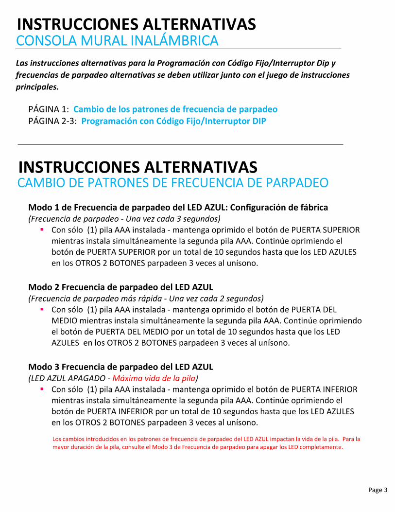
Las instrucciones alternativas para la Programación con Código Fijo/Interruptor Dip y
frecuencias de parpadeo alternativas se deben utilizar junto con el juego de instrucciones
principales.
Los cambios introducidos en los patrones de frecuencia de parpadeo del LED AZUL impactan la vida de la pila. Para la mayor duración de la pila, consulte el Modo 3 de Frecuencia de parpadeo para apagar los LED completamente.
Modo 1 de Frecuencia de parpadeo del LED AZUL: Configuración de fábrica (Frecuencia de parpadeo ‐ Una vez cada 3 segundos) Con sólo (1) pila AAA instalada ‐ mantenga oprimido el botón de PUERTA SUPERIOR
mientras instala simultáneamente la segunda pila AAA. Continúe oprimiendo el botón de PUERTA SUPERIOR por un total de 10 segundos hasta que los LED AZULES en los OTROS 2 BOTONES parpadeen 3 veces al unísono.
Modo 2 Frecuencia de parpadeo del LED AZUL (Frecuencia de parpadeo más rápida ‐ Una vez cada 2 segundos) Con sólo (1) pila AAA instalada ‐ mantenga oprimido el botón de PUERTA DEL
MEDIO mientras instala simultáneamente la segunda pila AAA. Continúe oprimiendo el botón de PUERTA DEL MEDIO por un total de 10 segundos hasta que los LED AZULES en los OTROS 2 BOTONES parpadeen 3 veces al unísono.
Modo 3 Frecuencia de parpadeo del LED AZUL (LED AZUL APAGADO ‐ Máxima vida de la pila) Con sólo (1) pila AAA instalada ‐ mantenga oprimido el botón de PUERTA INFERIOR
mientras instala simultáneamente la segunda pila AAA. Continúe oprimiendo el botón de PUERTA INFERIOR por un total de 10 segundos hasta que los LED AZULES en los OTROS 2 BOTONES parpadeen 3 veces al unísono.
PÁGINA 1: Cambio de los patrones de frecuencia de parpadeo PÁGINA 2‐3: Programación con Código Fijo/Interruptor DIP
INSTRUCCIONES ALTERNATIVASCAMBIO DE PATRONES DE FRECUENCIA DE PARPADEO
Page 4
INSTRUCCIONES ALTERNATIVASPROGRAMACIÓN CON INTERRUPTOR DIP/ CÓDIGO FIJO
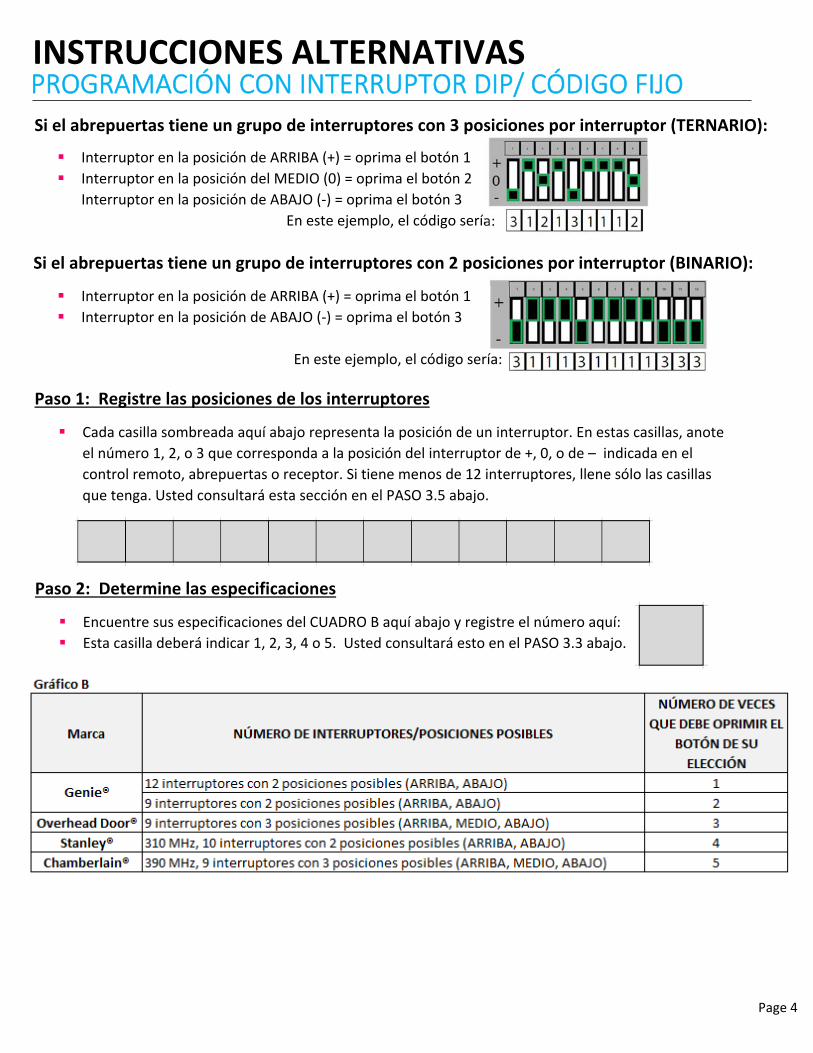
Si el abrepuertas tiene un grupo de interruptores con 3 posiciones por interruptor (TERNARIO):
Interruptor en la posición de ARRIBA (+) = oprima el botón 1
Interruptor en la posición del MEDIO (0) = oprima el botón 2
Interruptor en la posición de ABAJO (‐) = oprima el botón 3
En este ejemplo, el código sería:
Si el abrepuertas tiene un grupo de interruptores con 2 posiciones por interruptor (BINARIO):
Interruptor en la posición de ARRIBA (+) = oprima el botón 1
Interruptor en la posición de ABAJO (‐) = oprima el botón 3
En este ejemplo, el código sería:
Paso 1: Registre las posiciones de los interruptores
Cada casilla sombreada aquí abajo representa la posición de un interruptor. En estas casillas, anote
el número 1, 2, o 3 que corresponda a la posición del interruptor de +, 0, o de – indicada en el
control remoto, abrepuertas o receptor. Si tiene menos de 12 interruptores, llene sólo las casillas
que tenga. Usted consultará esta sección en el PASO 3.5 abajo.
Paso 2: Determine las especificaciones
Encuentre sus especificaciones del CUADRO B aquí abajo y registre el número aquí:
Esta casilla deberá indicar 1, 2, 3, 4 o 5. Usted consultará esto en el PASO 3.3 abajo.
Page 5
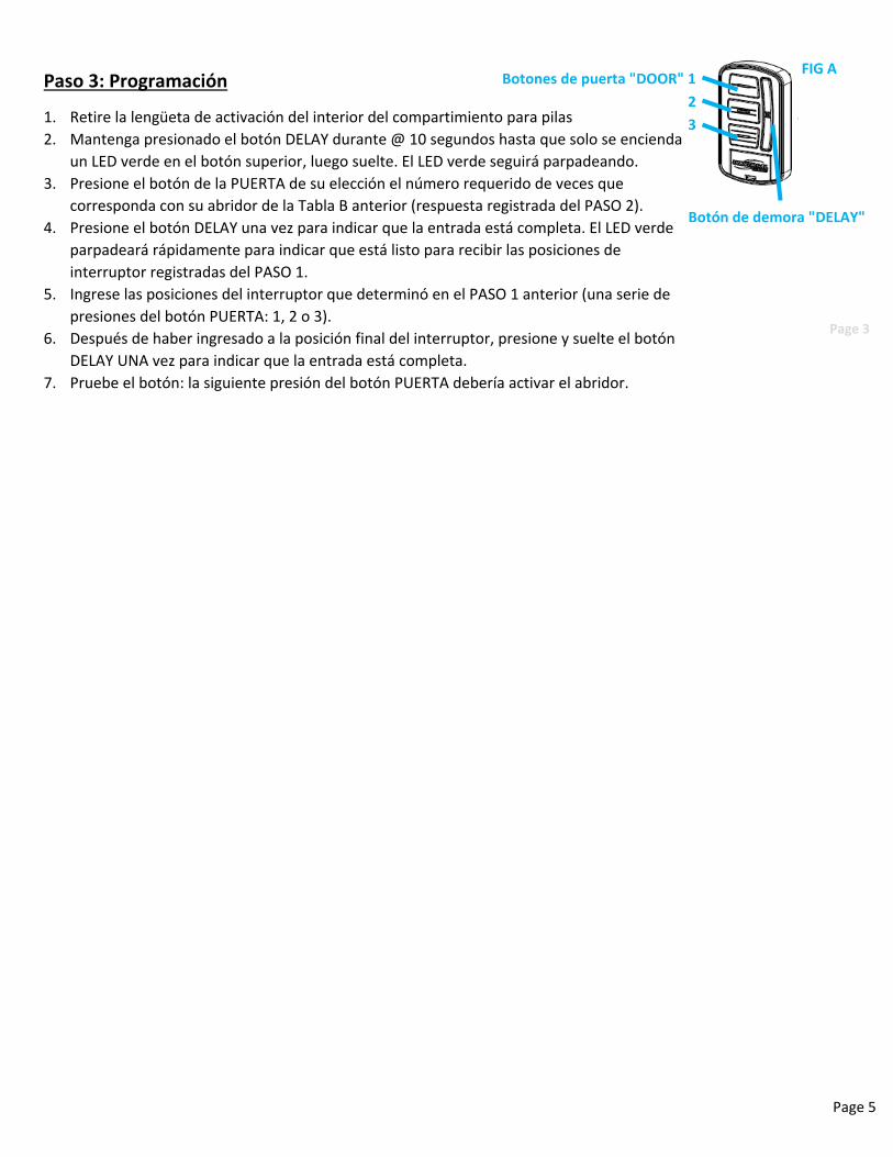
Paso 3: Programación
1. Retire la lengüeta de activación del interior del compartimiento para pilas
2. Mantenga presionado el botón DELAY durante @ 10 segundos hasta que solo se encienda
un LED verde en el botón superior, luego suelte. El LED verde seguirá parpadeando.
3. Presione el botón de la PUERTA de su elección el número requerido de veces que
corresponda con su abridor de la Tabla B anterior (respuesta registrada del PASO 2).
4. Presione el botón DELAY una vez para indicar que la entrada está completa. El LED verde
parpadeará rápidamente para indicar que está listo para recibir las posiciones de
interruptor registradas del PASO 1.
5. Ingrese las posiciones del interruptor que determinó en el PASO 1 anterior (una serie de
presiones del botón PUERTA: 1, 2 o 3).
6. Después de haber ingresado a la posición final del interruptor, presione y suelte el botón
DELAY UNA vez para indicar que la entrada está completa.
7. Pruebe el botón: la siguiente presión del botón PUERTA debería activar el abridor.
Botones de puerta "DOOR" 1
2
3
Botón de demora "DELAY"
FIG A
Page 3
41556.00XXX_FR
Instructions de la console murale universelle sans fil
06/2021
AVERTISSEMENTUNE PORTE EN MOUVEMENT PEUT CAUSER DE GRAVES
BLESSURES, VOIRE LA MORT.•N’installez PAS le transmetteur à moins que l’appareil de sécurité du dispositif de fermeture de porte ne fonctionne conformément au manuel du dispositif de fermeture de porte. •La console murale doit être montée à la vue de la porte, à au moins 5 pieds au-dessus du sol et il ne doit y avoir aucune pièce de porte en mouvement à proximité. •Éloignez les gens de l’ouverture lorsque la porte est en mouvement.•NE permettez PAS aux enfants de jouer avec le transmetteur ou le dispositif de fermeture de porte.
Si l’inversion de sécurité ne fonctionne pas correctement : •Fermez la porte, puis déconnectez le dispositif d’ouverture à l’aide de la poignée de dégagement manuel. •N’utilisez PAS le transmetteur ni le dispositif de fermeture de porte.•Référez-vous aux manuels du propriétaire de la porte et de l’ouvre-porte avant de tenter toute réparation.
!
FIG. A
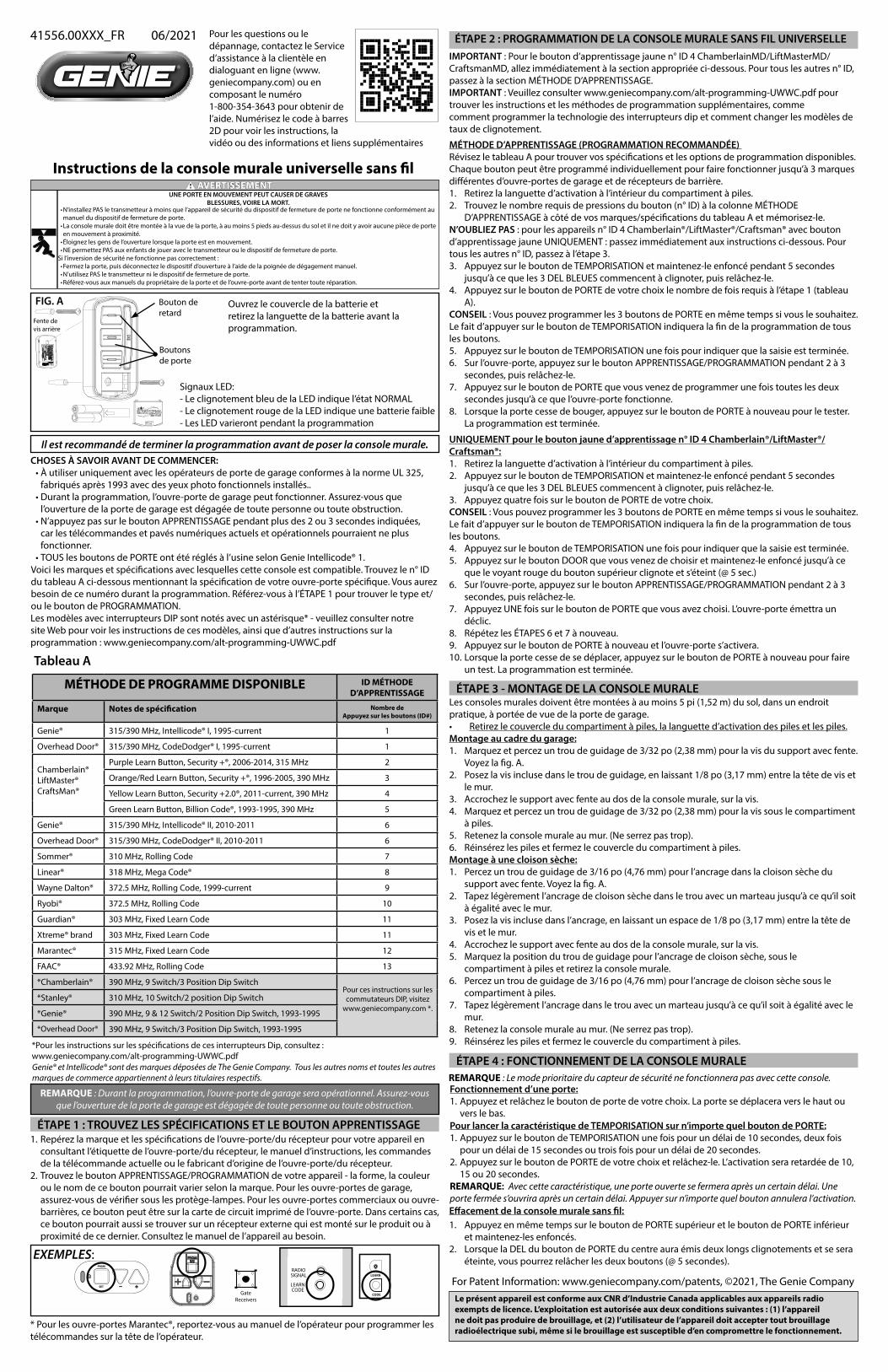
Pour les questions ou le dépannage, contactez le Service d’assistance à la clientèle en dialoguant en ligne (www.geniecompany.com) ou en composant le numéro 1-800-354-3643 pour obtenir de l’aide. Numérisez le code à barres 2D pour voir les instructions, la vidéo ou des informations et liens supplémentaires
Ouvrez le couvercle de la batterie et retirez la languette de la batterie avant la programmation.
Signaux LED:- Le clignotement bleu de la LED indique l’état NORMAL- Le clignotement rouge de la LED indique une batterie faible- Les LED varieront pendant la programmation
Il est recommandé de terminer la programmation avant de poser la console murale.
REMARQUE : Durant la programmation, l’ouvre-porte de garage sera opérationnel. Assurez-vous que l’ouverture de la porte de garage est dégagée de toute personne ou toute obstruction.
Tableau A
Genie® et Intellicode® sont des marques déposées de The Genie Company. Tous les autres noms et toutes les autres marques de commerce appartiennent à leurs titulaires respectifs.
*Pour les instructions sur les spécifications de ces interrupteurs Dip, consultez : www.geniecompany.com/alt-programming-UWWC.pdf
CHOSES À SAVOIR AVANT DE COMMENCER:•À utiliser uniquement avec les opérateurs de porte de garage conformes à la norme UL 325,
fabriqués après 1993 avec des yeux photo fonctionnels installés..•Durant la programmation, l’ouvre-porte de garage peut fonctionner. Assurez-vous que
l’ouverture de la porte de garage est dégagée de toute personne ou toute obstruction.•N’appuyez pas sur le bouton APPRENTISSAGE pendant plus des 2 ou 3 secondes indiquées,
car les télécommandes et pavés numériques actuels et opérationnels pourraient ne plus fonctionner. •TOUS les boutons de PORTE ont été réglés à l’usine selon Genie Intellicode® 1.
Les modèles avec interrupteurs DIP sont notés avec un astérisque* - veuillez consulter notre site Web pour voir les instructions de ces modèles, ainsi que d’autres instructions sur la programmation : www.geniecompany.com/alt-programming-UWWC.pdf
Voici les marques et spécifications avec lesquelles cette console est compatible. Trouvez le n° ID du tableau A ci-dessous mentionnant la spécification de votre ouvre-porte spécifique. Vous aurez besoin de ce numéro durant la programmation. Référez-vous à l’ÉTAPE 1 pour trouver le type et/ou le bouton de PROGRAMMATION.
ÉTAPE 1 : TROUVEZ LES SPÉCIFICATIONS ET LE BOUTON APPRENTISSAGE 1. Repérez la marque et les spécifications de l’ouvre-porte/du récepteur pour votre appareil en
consultant l’étiquette de l’ouvre-porte/du récepteur, le manuel d’instructions, les commandes de la télécommande actuelle ou le fabricant d’origine de l’ouvre-porte/du récepteur.
2. Trouvez le bouton APPRENTISSAGE/PROGRAMMATION de votre appareil - la forme, la couleur ou le nom de ce bouton pourrait varier selon la marque. Pour les ouvre-portes de garage, assurez-vous de vérifier sous les protège-lampes. Pour les ouvre-portes commerciaux ou ouvre-barrières, ce bouton peut être sur la carte de circuit imprimé de l’ouvre-porte. Dans certains cas, ce bouton pourrait aussi se trouver sur un récepteur externe qui est monté sur le produit ou à proximité de ce dernier. Consultez le manuel de l’appareil au besoin.
PRGM
SET
RADIOSIGNAL
LEARNCODE
CODE
LEARN
GateReceivers
* Pour les ouvre-portes Marantec®, reportez-vous au manuel de l’opérateur pour programmer les télécommandes sur la tête de l’opérateur.
ÉTAPE 2 : PROGRAMMATION DE LA CONSOLE MURALE SANS FIL UNIVERSELLE IMPORTANT : Pour le bouton d’apprentissage jaune n° ID 4 ChamberlainMD/LiftMasterMD/CraftsmanMD, allez immédiatement à la section appropriée ci-dessous. Pour tous les autres n° ID, passez à la section MÉTHODE D’APPRENTISSAGE.IMPORTANT : Veuillez consulter www.geniecompany.com/alt-programming-UWWC.pdf pour trouver les instructions et les méthodes de programmation supplémentaires, commecomment programmer la technologie des interrupteurs dip et comment changer les modèles de taux de clignotement.
MÉTHODE D’APPRENTISSAGE (PROGRAMMATION RECOMMANDÉE) Révisez le tableau A pour trouver vos spécifications et les options de programmation disponibles. Chaque bouton peut être programmé individuellement pour faire fonctionner jusqu’à 3 marques différentes d’ouvre-portes de garage et de récepteurs de barrière. 1. Retirez la languette d’activation à l’intérieur du compartiment à piles.2. Trouvez le nombre requis de pressions du bouton (n° ID) à la colonne MÉTHODE
D’APPRENTISSAGE à côté de vos marques/spécifications du tableau A et mémorisez-le. N’OUBLIEZ PAS : pour les appareils n° ID 4 Chamberlain®/LiftMaster®/Craftsman® avec bouton d’apprentissage jaune UNIQUEMENT : passez immédiatement aux instructions ci-dessous. Pour tous les autres n° ID, passez à l’étape 3.3. Appuyez sur le bouton de TEMPORISATION et maintenez-le enfoncé pendant 5 secondes
jusqu’à ce que les 3 DEL BLEUES commencent à clignoter, puis relâchez-le.4. Appuyez sur le bouton de PORTE de votre choix le nombre de fois requis à l’étape 1 (tableau
A).CONSEIL : Vous pouvez programmer les 3 boutons de PORTE en même temps si vous le souhaitez. Le fait d’appuyer sur le bouton de TEMPORISATION indiquera la fin de la programmation de tous les boutons. 5. Appuyez sur le bouton de TEMPORISATION une fois pour indiquer que la saisie est terminée. 6. Sur l’ouvre-porte, appuyez sur le bouton APPRENTISSAGE/PROGRAMMATION pendant 2 à 3
secondes, puis relâchez-le.7. Appuyez sur le bouton de PORTE que vous venez de programmer une fois toutes les deux
secondes jusqu’à ce que l’ouvre-porte fonctionne. 8. Lorsque la porte cesse de bouger, appuyez sur le bouton de PORTE à nouveau pour le tester.
La programmation est terminée.
UNIQUEMENT pour le bouton jaune d’apprentissage n° ID 4 Chamberlain®/LiftMaster®/Craftsman®:1. Retirez la languette d’activation à l’intérieur du compartiment à piles.2. Appuyez sur le bouton de TEMPORISATION et maintenez-le enfoncé pendant 5 secondes
jusqu’à ce que les 3 DEL BLEUES commencent à clignoter, puis relâchez-le. 3. Appuyez quatre fois sur le bouton de PORTE de votre choix. CONSEIL : Vous pouvez programmer les 3 boutons de PORTE en même temps si vous le souhaitez. Le fait d’appuyer sur le bouton de TEMPORISATION indiquera la fin de la programmation de tous les boutons. 4. Appuyez sur le bouton de TEMPORISATION une fois pour indiquer que la saisie est terminée. 5. Appuyez sur le bouton DOOR que vous venez de choisir et maintenez-le enfoncé jusqu’à ce
que le voyant rouge du bouton supérieur clignote et s’éteint (@ 5 sec.) 6. Sur l’ouvre-porte, appuyez sur le bouton APPRENTISSAGE/PROGRAMMATION pendant 2 à 3
secondes, puis relâchez-le. 7. Appuyez UNE fois sur le bouton de PORTE que vous avez choisi. L’ouvre-porte émettra un
déclic. 8. Répétez les ÉTAPES 6 et 7 à nouveau. 9. Appuyez sur le bouton de PORTE à nouveau et l’ouvre-porte s’activera. 10. Lorsque la porte cesse de se déplacer, appuyez sur le bouton de PORTE à nouveau pour faire
un test. La programmation est terminée.
Les consoles murales doivent être montées à au moins 5 pi (1,52 m) du sol, dans un endroit pratique, à portée de vue de la porte de garage.• Retirez le couvercle du compartiment à piles, la languette d’activation des piles et les piles.Montage au cadre du garage:1. Marquez et percez un trou de guidage de 3/32 po (2,38 mm) pour la vis du support avec fente.
Voyez la fig. A.2. Posez la vis incluse dans le trou de guidage, en laissant 1/8 po (3,17 mm) entre la tête de vis et
le mur.3. Accrochez le support avec fente au dos de la console murale, sur la vis.4. Marquez et percez un trou de guidage de 3/32 po (2,38 mm) pour la vis sous le compartiment
à piles.5. Retenez la console murale au mur. (Ne serrez pas trop). 6. Réinsérez les piles et fermez le couvercle du compartiment à piles.Montage à une cloison sèche:1. Percez un trou de guidage de 3/16 po (4,76 mm) pour l’ancrage dans la cloison sèche du
support avec fente. Voyez la fig. A.2. Tapez légèrement l’ancrage de cloison sèche dans le trou avec un marteau jusqu’à ce qu’il soit
à égalité avec le mur.3. Posez la vis incluse dans l’ancrage, en laissant un espace de 1/8 po (3,17 mm) entre la tête de
vis et le mur.4. Accrochez le support avec fente au dos de la console murale, sur la vis.5. Marquez la position du trou de guidage pour l’ancrage de cloison sèche, sous le
compartiment à piles et retirez la console murale. 6. Percez un trou de guidage de 3/16 po (4,76 mm) pour l’ancrage de cloison sèche sous le
compartiment à piles. 7. Tapez légèrement l’ancrage dans le trou avec un marteau jusqu’à ce qu’il soit à égalité avec le
mur.8. Retenez la console murale au mur. (Ne serrez pas trop).9. Réinsérez les piles et fermez le couvercle du compartiment à piles.
ÉTAPE 3 - MONTAGE DE LA CONSOLE MURALE
RearScrew Slot
Bouton de retard
Boutons de porte
Effacement de la console murale sans fil:1. Appuyez en même temps sur le bouton de PORTE supérieur et le bouton de PORTE inférieur
et maintenez-les enfoncés.2. Lorsque la DEL du bouton de PORTE du centre aura émis deux longs clignotements et se sera
éteinte, vous pourrez relâcher les deux boutons (@ 5 secondes).
Pour lancer la caractéristique de TEMPORISATION sur n’importe quel bouton de PORTE:1. Appuyez sur le bouton de TEMPORISATION une fois pour un délai de 10 secondes, deux fois
pour un délai de 15 secondes ou trois fois pour un délai de 20 secondes.2. Appuyez sur le bouton de PORTE de votre choix et relâchez-le. L’activation sera retardée de 10,
15 ou 20 secondes.REMARQUE: Avec cette caractéristique, une porte ouverte se fermera après un certain délai. Une porte fermée s’ouvrira après un certain délai. Appuyer sur n’importe quel bouton annulera l’activation.
ÉTAPE 4 : FONCTIONNEMENT DE LA CONSOLE MURALEREMARQUE : Le mode prioritaire du capteur de sécurité ne fonctionnera pas avec cette console.Fonctionnement d’une porte:1. Appuyez et relâchez le bouton de porte de votre choix. La porte se déplacera vers le haut ou
vers le bas.
Fente de vis arrière
Le présent appareil est conforme aux CNR d’Industrie Canada applicables aux appareils radio exempts de licence. L’exploitation est autorisée aux deux conditions suivantes : (1) l’appareil ne doit pas produire de brouillage, et (2) l’utilisateur de l’appareil doit accepter tout brouillage radioélectrique subi, même si le brouillage est susceptible d’en compromettre le fonctionnement.
*Overhead Door® 390 MHz, 9 Switch/3 Position Dip Switch, 1993-1995
Pour ces instructions sur les commutateurs DIP, visitez
www.geniecompany.com *.
RBarnes
Text Box
41812.00892_FR
RBarnes
Typewritten Text
RBarnes
Typewritten Text
Page 6
AUTRES INSTRUCTIONSCONSOLE MURALE SANS FIL UNIVERSELLE
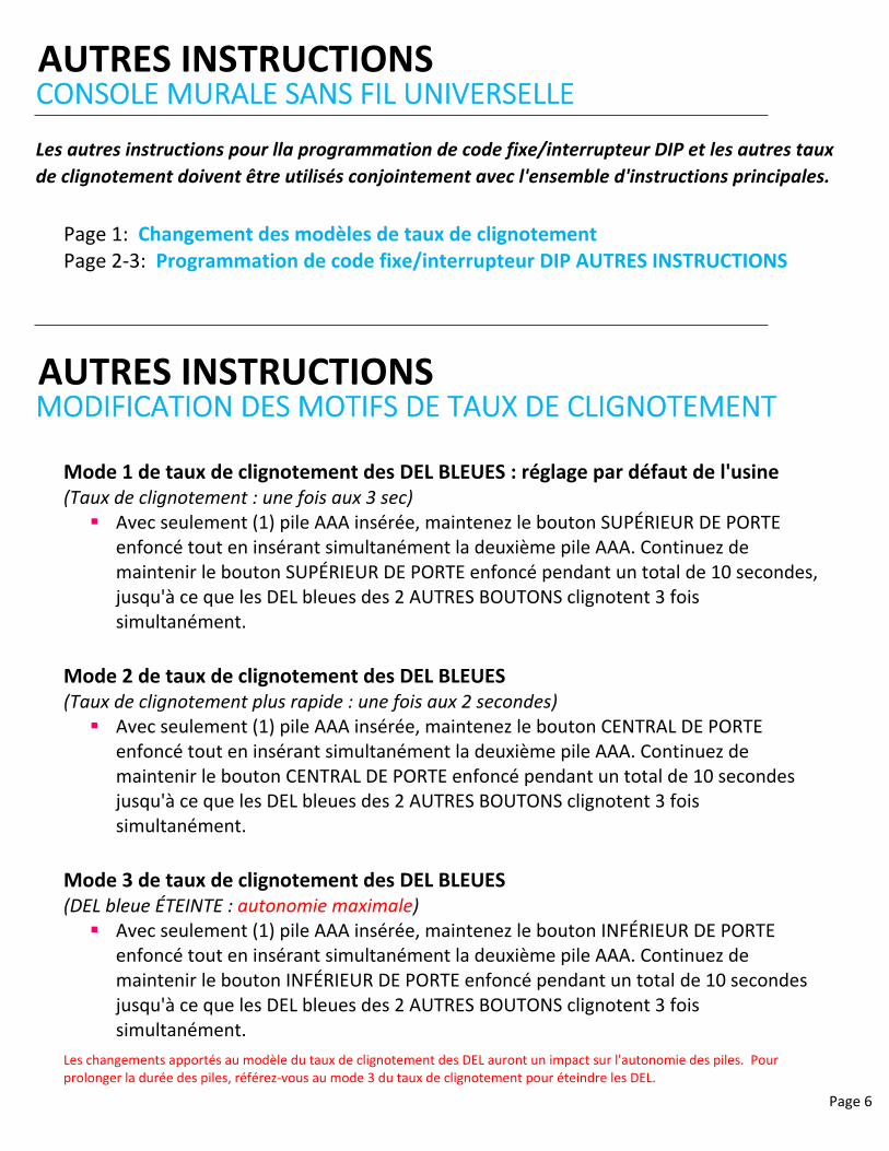
Les autres instructions pour lla programmation de code fixe/interrupteur DIP et les autres taux
de clignotement doivent être utilisés conjointement avec l'ensemble d'instructions principales.
Les changements apportés au modèle du taux de clignotement des DEL auront un impact sur l'autonomie des piles. Pour prolonger la durée des piles, référez‐vous au mode 3 du taux de clignotement pour éteindre les DEL.
Mode 1 de taux de clignotement des DEL BLEUES : réglage par défaut de l'usine (Taux de clignotement : une fois aux 3 sec) Avec seulement (1) pile AAA insérée, maintenez le bouton SUPÉRIEUR DE PORTE
enfoncé tout en insérant simultanément la deuxième pile AAA. Continuez de maintenir le bouton SUPÉRIEUR DE PORTE enfoncé pendant un total de 10 secondes, jusqu'à ce que les DEL bleues des 2 AUTRES BOUTONS clignotent 3 fois simultanément.
Mode 2 de taux de clignotement des DEL BLEUES (Taux de clignotement plus rapide : une fois aux 2 secondes) Avec seulement (1) pile AAA insérée, maintenez le bouton CENTRAL DE PORTE
enfoncé tout en insérant simultanément la deuxième pile AAA. Continuez de maintenir le bouton CENTRAL DE PORTE enfoncé pendant un total de 10 secondes jusqu'à ce que les DEL bleues des 2 AUTRES BOUTONS clignotent 3 fois simultanément.
Mode 3 de taux de clignotement des DEL BLEUES (DEL bleue ÉTEINTE : autonomie maximale) Avec seulement (1) pile AAA insérée, maintenez le bouton INFÉRIEUR DE PORTE
enfoncé tout en insérant simultanément la deuxième pile AAA. Continuez de maintenir le bouton INFÉRIEUR DE PORTE enfoncé pendant un total de 10 secondes jusqu'à ce que les DEL bleues des 2 AUTRES BOUTONS clignotent 3 fois simultanément.
Page 1: Changement des modèles de taux de clignotement Page 2‐3: Programmation de code fixe/interrupteur DIP AUTRES INSTRUCTIONS
AUTRES INSTRUCTIONSMODIFICATION DES MOTIFS DE TAUX DE CLIGNOTEMENT
Page 7
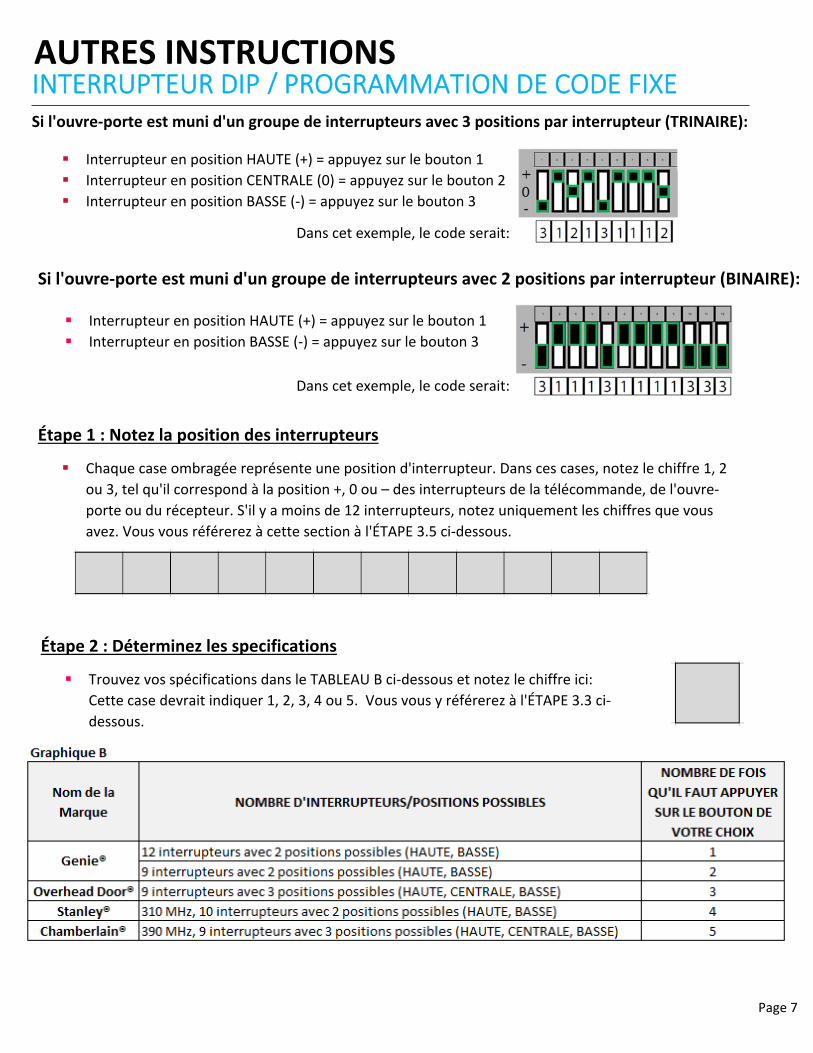
AUTRES INSTRUCTIONSINTERRUPTEUR DIP / PROGRAMMATION DE CODE FIXE
Étape 1 : Notez la position des interrupteurs
Chaque case ombragée représente une position d'interrupteur. Dans ces cases, notez le chiffre 1, 2
ou 3, tel qu'il correspond à la position +, 0 ou – des interrupteurs de la télécommande, de l'ouvre‐
porte ou du récepteur. S'il y a moins de 12 interrupteurs, notez uniquement les chiffres que vous
avez. Vous vous référerez à cette section à l'ÉTAPE 3.5 ci‐dessous.
Étape 2 : Déterminez les specifications
Trouvez vos spécifications dans le TABLEAU B ci‐dessous et notez le chiffre ici:
Cette case devrait indiquer 1, 2, 3, 4 ou 5. Vous vous y référerez à l'ÉTAPE 3.3 ci‐
dessous.
Si l'ouvre‐porte est muni d'un groupe de interrupteurs avec 3 positions par interrupteur (TRINAIRE):
Interrupteur en position HAUTE (+) = appuyez sur le bouton 1
Interrupteur en position CENTRALE (0) = appuyez sur le bouton 2
Interrupteur en position BASSE (‐) = appuyez sur le bouton 3
Dans cet exemple, le code serait:
Si l'ouvre‐porte est muni d'un groupe de interrupteurs avec 2 positions par interrupteur (BINAIRE):
Interrupteur en position HAUTE (+) = appuyez sur le bouton 1
Interrupteur en position BASSE (‐) = appuyez sur le bouton 3
Dans cet exemple, le code serait:
Page 8
Étape 3 : Programmation
1. Retirez la languette d'activation à l'intérieur du compartiment à piles.
2. Appuyez sur le bouton DELAY et maintenez‐le enfoncé pendant @ 10 secondes
jusqu'à ce que seule une LED verte s'allume sur le bouton supérieur ‐ puis relâchez.
La LED verte continuera à clignoter.
3. Appuyez sur le bouton PORTE de votre choix le nombre de fois requis correspondant
à votre ouvre‐porte du tableau B ci‐dessus (réponse enregistrée à l'ÉTAPE 2).
4. Appuyez une fois sur le bouton DELAY pour signaler que l'entrée est terminée. Le
voyant vert clignotera rapidement pour indiquer qu'il est prêt à recevoir les
positions de commutation enregistrées à partir de l'ÉTAPE 1.
5. Entrez les positions des commutateurs que vous avez déterminées à l'ÉTAPE 1 ci‐
dessus (une série d'appuis sur le bouton DOOR ‐ 1, 2 ou 3).
6. Une fois que vous êtes entré dans la position finale du commutateur, appuyez et
relâchez le bouton DELAY UNE fois pour signaler que l'entrée est terminée.
7. Testez le bouton ‐ la prochaine pression sur le bouton DOOR devrait activer l'ouvre‐