Page 1
UNIVERSITI TEKNIKAL MALAYSIA MELAKA
COMPUTER INTEGRATED MANUFACTURING (CONTINUITY ELECTRICAL BOARD CHECKER)
This report submitted in accordance with requirement of the UniversitiTeknikal Malaysia Melaka (UTeM) for the Bachelor Degree of Manufacturing Engineering
(Robotic and Automation) with Honours.
by
MUHAMMAD ZUFAR BIN JURIJ (B050710059)
FACULTY OF MANUFACTURING ENGINEERING 2011
Page 2
UNIVERSITI TEKNIKAL MALAYSIA MELAKA
BORANG PENGESAHAN STATUS LAPORAN PROJEK SARJANA MUDA
TAJUK:Computer Integrated Manufacturing(Continuity electrical board checker)
SESI PENGAJIAN: 2010/11 Semester 2 SayaMUHAMMAD ZUFAR BIN JURIJ mengakumembenarkanLaporan PSM inidisimpan di PerpustakaanUniversitiTeknikal Malaysia Melaka (UTeM) dengansyarat-syaratkegunaansepertiberikut:
1. Laporan PSM adalah hak milik Universiti Teknikal Malaysia Melaka dan penulis. 2. Perpustakaan Universiti Teknikal Malaysia Melaka dibenarkan membuat salinan
untuk tujuan pengajian sahaja dengan izin penulis. 3. Perpustakaan dibenarkan membuat salinan laporan PSM ini sebagai bahan
pertukaran antara institusi pengajian tinggi.
4. **Silatandakan (√)
SULIT
TERHAD
TIDAK TERHAD
(Mengandungimaklumat yang berdarjahkeselamatanataukepentingan Malaysia yang
termaktub di dalam AKTA RAHSIA RASMI 1972)
(Mengandungimaklumat TERHAD yang telahditentukanolehorganisasi/badan di
manapenyelidikandijalankan)
AlamatTetap:
63, PersiaranSeroja 5,
Taman Seroja, 33100 Kuala Kangsar
PerakDarulRidzuan.
Tarikh: 18 MAY 2011
Disahkanoleh:
MOHD NAZRIN BIN MUHAMMAD Cop Rasmi: Tarikh: 18 MAY 2011
** JikaLaporan PSM ini SULIT atau TERHAD, silalampirkansuratdaripadapihakberkuasa/organisasiberkenaandenganmenyatakansekalisebabdantem
pohlaporan PSM iniperludikelaskansebagai SULIT atau TERHAD.
Page 3
DECLARATION
I hereby, declared this report entitled “Computer Integrated Manufacturing (Continuity
Electrical Board Checker)”is the results of my own research except as cited in references.
Signature : ………………………………………….
Author’s Name : MUHAMMAD ZUFAR BIN JURIJ
Date : 18 MAY 2011
Page 4
APPROVAL
This report is submitted to the Faculty of Manufacturing Engineering of UTeM as a
partial fulfillment of the requirements for the degree of Bachelor of Manufacturing
Engineering (Robotic & Automation) with Honours. The member of the supervisory
committee is as follow:
………………………………
Supervisor
(Signature &Official Stamp of Supervisor)
Page 5
i
ABSTRAK
Projek Sarjana Muda(PSM) adalah satuprojek yangstandarduntukmendapatkanijazah
sarjana muda. Terdapatbanyaktajuk yangUTeMtelah berikantapisayatelah membuat
pilihan untuk memilih tajukberjudulProjek Integrasi Pembuatan berkomputer.
Iniadalahsuatu peluang bagi
sayauntukmenunjukkankemahirandanpengetahuanyangtelahsayapelajariselamamenu
ntutdiUteM untuk di aplikasikan didalam projek ini. Bagi skop untuk projekCIMsaya
iniadalahuntukmembina suatusistemuntuk memeriksa kesinambunganarus elektrik di
dalam papanlitar eletrik buatan sendiri.
Papanelektrikakanditempatkanpadasebuahjigkhususyang sesuai pada pembawa
produk iaitu papan litar elektrik buatan sendiri di dalam CIM ini.
Stesensatuakanmenyemakkesinambunganantaraduatitikdipapandanpapanyanggagaluj
ianakandikeluarkan dari konveyordistesendua. Di dalam Makmal CIM
UTeMterdapat2SiemensPLC, 2stesendankonveyor.
PLCpertamaakanmengawalkonveyordanstesen1danPLCyang
lainakanmengawalstesen2.
Page 6
ii
ABSTRACT
Final year project (PSM) is the standard project for get a degree certificate. There are
many titles that UTeM given but I was interesting the title Computer Integrated
Manufacturing Project. This is opportunities to show the skills and knowledge that I
have learned during study in UTeM. The scope for CIM Project is to develop a
continuity electrical board checker system on CIM where it performs continuity test
on the self-made circuit board. The electrical board will be placed on a special jig
that is fixed to the CIM’s carrier base. The probing station will check the continuity
between the two points on the board and the board which failed the test will be
removed at the reject station.In the UTeM CIM lab is provide 2 Siemens PLCs, 2
workstations and a conveyer. The first PLC will control conveyer and workstation 1
and other PLC will control the workstation 2.
Page 7
iv
ACKNOWLEDGEMENTS
During this final year project, so many people and individual are involved;
without their involvement, I am sure that there difficulties that I have to face. Thus,
here in opportunity, I would like to express millions of thank to UniversitiTeknikal
Malaysia Melaka (UTeM) because give me a million of knowledge and skills and to
those who given their fully support and cooperation during my final year project at
UniversitiTeknikal Malaysia Melaka (UTeM) from the beginning until the end of
product.
I would like to dedicate my deepest gratitude to my academy supervisor Mr.
MohdNazrin Bin Muhammad for his invaluable guidance, help, information,
encouragement throughout the duration of my final year project. I wish to thank
Manufacturing Faculty staff for the generous sharing of his time, experience,
knowledge and advice.
My sincere appreciation also goes to my family and friends as the endless
concern, financial support, moral support, and understanding and inspired me to
complete this final year project successfully.
Page 8
v
DEDICATION
To my beloved parents, Mr. Jurij Bin Jalaludinand Mrs. SabaridahBinti
Ismail for their seems less expression of love and fully support for me during my
study at UniversitiTeknikal Malaysia Melaka (UTeM) and my university,
UniversitiTeknikal Malaysia Melaka (UTeM) and then to finish up this Bachelor
Project report.
To my academic supervisor for this project, Mr. MohdNazrin bin
Muhammadforhis invaluable guidance and information to me finish up this report
and I would like to express thankful also to him for all of his advice and moral
support to me.
Lastly, I would like to express thank for all staff of Manufacturing Faculty
UTeM and to my friends with always support and advise me during completing the
final year project that had given.
Page 9
vi
TABLE OF CONTENT
Abstrak i
Abstract ii
Dedication iii
Acknowledgement iv
Table of Content v
List of Tables viii
List of Figures ix
List of Abbreviations xiii
1. INTRODUCTION 1
1.1 Problem Statement 4
1.2 Related Scope 4
1.3 Scope 5
1.4 Objective 5
2. LITERATURE REVIEW 6
2.1 Sensors 7
2.2 Actuator 8
2.2.1 DC Motor 9
2.2.1.1 Brushed DC Motor 9
2.2.1.2 Brushless DC Motor 10
2.2.1.3 Inductive DC Motor 11
2.2.2 Pneumatic Cylinder 12
2.3 Microcontroller 14
2.3.1 Siemens PLC 14
2.3.2 Ladder Diagram 20
2.4 Compact Inverter 23
2.5 Solenoid Valve 24
Page 10
vii
2.6 Continuity Test 28
2.6.1 Continuity Board Tester 28
2.6.2 Electrical Probe 29
2.7 History CIM 30
3. METHODOLOGY 31
3.1 CIM Layout 33
3.2 Flow Chart 35
3.2.1 Main Flow Chart 35
3.2.2 Sub-Flow Chart: Workstation 1 36
3.2.2.1 Sub-flow chart for workstation 1 37
3.2.3 Sub-Flow Chart: Conveyer movement 38
3.2.4 Sub-Flow Chart: Workstation 2 39
3.3 List of Material 40
3.4 Workstation 1 (Board Checker) 41
3.5 Workstation 2 (Rejecter) 43
3.6 The jigs for the base 44
3.7 Self-made Circuit Board (Product) 47
3.8 Programmable Logic Control 48
3.9 Hardware Setup 49
4. DEVELOPMENT OF CIM 52
4.1 Workstation 1 52
4.1.1 Placement and Adjustment 53
4.1.2 Connection in PLC 1 54
4.2 Workstation2 58
4.2.1 Adjustment for workstation 2 59
4.2.2 Connection in PLC2 64
4.3 Ladder Diagram for PLC1 65
4.4 Ladder Diagram for PLC2 69
Page 11
viii
5. TESTING< RESULT AND DISCUSSION 74
5.1 Special Jigs (BASE) 74
5.2 Testing workstation 1 77
5.2.1 The Result Workstation 1 79
5.3 Testing Workstation 2 80
5.3.1 Vacuum Gripper 80
5.3.2 Result Workstation 2 81
5.4 Final Result 82
6. CONCLUSION AND SUGGESTION 84
REFERENCE 86
APPENDICES 88
Page 12
ix
LIST OF TABLE
2.1 Input Table 22
2.2 Output Table 23
4.1 Result testing workstation 1 58
4.2 Connection in workstation 2 64
5.1 Analyze the special jigs 75
5.2 Analyze the bottom of special jigs 76
5.3 Result testing workstation 1 79
5.4 Timing Result 82
5.5 Final Result 1 82
5.4 Final Result 2 83
Page 13
x
LIST OF FIGURES
1.1 Modern and classic manufacturing layout. 1
1.2 Example CIM of Dave Cimma Company. 2
1.3 UTeM CIM Lab. 5
2.1 Electronic proximity sensor. 7
2.2 Electronic proximity diagram. 7
2.3 Brushed Motor. 10
2.4 Induction motor. 11
2.5 Pneumatic cylinder. 12
2.6 Pneumatic Cylinder Diagram. 13
2.7 Siemens PLC. 14
2.8 Attach sensor on PLC diagram. 16
2.9 Attach actuator on PLC diagram. 16
2.10 USB/PPI+ programming cable. 17
2.11 VF-S7e is the compact and simple inverter. 24
2.12 5 Port Pilot Operated Solenoid Valve. 25
2.13 Solenoid valve diagram. 26
2.14 Continuity test by operator. 29
2.15 Probes. 30
Page 14
xi
3.1 CIM diagram. 33
3.2 Pneumatic cylinder pusher. 34
3.3 Probes. 41
3.4 Probes with spring. 41
3.5 Probes attach on cylinder. 41
3.6 Workstation 2. 43
3.7 The base on the CIM conveyer. 44
3.8 The acrylic. 45
3.9 The acrylic with woods stand. 45
3.10 The jig for base of CIM (design 1). 46
3.11 The jig for base of CIM (design 2). 46
3.12 Self-made Circuit Board. 47
3.13 Siemens PLC. 48
3.14 PLC installation. 48
4.1 Original workstation 1. 53
4.2 Adjustment workstation 1. 54
4.3 Connection between workstation 1, conveyer and PLC 1. 55
4.4 Solenoid valve connection. 55
4.5 Solenoid valve connection with relay. 56
4.6 Probes Connection. 57
4.7 Final Connection for workstation 1. 57
4.8 Original workstation 2. 59
Page 15
xii
4.9 Component removed. 60
4.10 Air supply shared. 61
4.11 Motor connection for workstation 2. 61
4.12 The result reduces weight. 62
4.13 Change the cylinder. 63
4.14 Remove aluminum plate. 63
4.15 Attach another power supply. 64
4.16 Connection for PLC 2. 65
4.17 Declaration for PLC 1. 65
4.18 Network 1 for PLC 1. 66
4.19 Network 2 and 3 for PLC 1. 66
4.20 Network 4 for PLC 1. 67
4.21 Network 5 for PLC 1. 67
4.22 Network 6 and 7 for PLC 1. 68
4.23 Network 8 and 9 for PLC 1. 68
4.24 Network 10 for PLC 1. 69
4.25 Declaration for PLC 2. 69
4.26 Network 1 and 2 for PLC 2. 70
4.27 Network 3 and 4 for PLC 2. 70
4.28 Network 5 and 6 for PLC 2. 71
4.29 Network 7, 8, 9 and 10 for PLC 2. 72
4.30 Network 11 and 12 for PLC 2. 73
Page 16
xiii
5.1 Distance between special jigs and workstations. 75
5.2 Design for special jigs. 76
5.3 Probe design. 78
5.4 Final Probe Design. 78
5.5 Workstation 1 final. 79
5.6 Vacuum cup. 80
Page 17
xiv
LIST OF ABBREVIATIONS
AC Alternating Current
CAD - Computer Aided Design
CAM - Computer Aided Manufacturing
CIM - Computer Integrated Manufacturing
CPU Central Processing Unit
DC Direct Current
I/O - Input and Output
OK Good Product
NG Fail Product
PLC Programmable Logic Controller
Page 18
1
CHAPTER 1 INTRODUCTION
In 1980, scientists and engineers are trying to improve the manufacturing process by
introducing more and more computerized systems on the manufacturing process. A
classic manufacturing plant may have many software systems. Some of these
systems can be do like manufacturing system, production scheduling system,
equipment andlabour utilization system, supervisory control system, material
tracking system, equipment monitoring system, shop floor data gathering system,
statistical process control system, and preventive maintenance system.
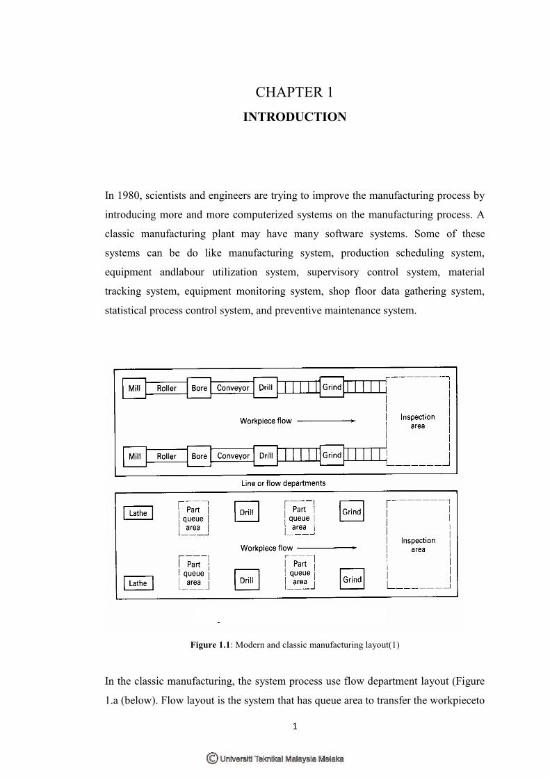
Figure 1.1: Modern and classic manufacturing layout(1)
In the classic manufacturing, the system process use flow department layout (Figure
1.a (below). Flow layout is the system that has queue area to transfer the workpieceto
Page 19
2
another workstation. The system is normally uses manual system to transfer
workpiece in the production line that will increase the labour cost and cycle time.
The line department layout (Figure 1.a (above)) has uses roller and conveyor to
transfer the workpiece. The systems that used conveyor are known as automated
system. Computer Integrated Manufacturing is a combination of software and
hardware to make the system work exactly as what the task given for example
assembly line. The word Integration in term of manufacturing might be visualized as
the figure below.
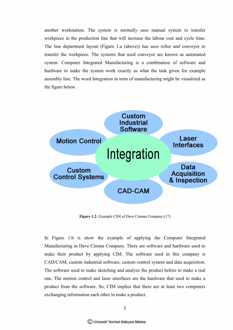
Figure 1.2: Example CIM of Dave Cimma Company.(17)
In Figure 1.b is show the example of applying the Computer Integrated
Manufacturing in Dave Cimma Company. There are software and hardware used to
make their product by applying CIM. The software used in this company is
CAD/CAM, custom industrial software, custom control system and data acquisition.
The software used to make sketching and analyze the product before to make a real
one. The motion control and laser interfaces are the hardware that used to make a
product from the software. So, CIM implies that there are at least two computers
exchanging information each other to make a product.
Page 20
3
The term CIM is a method of manufacturing and the name of a computer-automated
system in which individual engineering, production, marketing, and support
functions of a manufacturing enterprise are organized. In a CIM system functional
areas such as design, analysis, planning, purchasing, cost accounting, inventory
control, and distribution are linked through the computer with factory floor functions
such as materials handling and management, providing direct control and monitoring
of all process operations.(3)
As the method of manufacturing, three components distinguish CIM from other
manufacturing methodologies are:
Means for data storage, retrieval, manipulation and presentation;
Mechanisms for sensing state and modifying processes;
Algorithms for uniting the data processing component with the
sensor/modification component.
CIM implies that there are at least two computers exchanging information, e.g. the
controller of an arm robot and the micro-controller of a CNC machine.
Some factors involved when considering a CIM implementation are the production
volume, the experience of the company or personnel to make the integration, the
level of the integration into the product itself and the integration of the production
processes. CIM can be most useful in high level of ICT is used in many of company
or facility, such as CAD/CAM systems, the availability of process planning and its
data. It also give many advantages such as increase productivity, reduce overall lead
time, decrease design costs and cut work-in-process inventory.
Page 21
4
1.1 Problem Statement
This project aim to develop a continuity electrical board checker that checks
electrical boards. There are many problems occur to check the electrical boards by
operator in normal operation. The problems are:
1. Confusion : The operators may have some confusion while
checking the electrical boards because loss of focus in a long time.
2. Unproductive time: The operator can make mistake or lost spirit in
workspace that will increase a lead time of production time.
3. Cost : In term of a large production plan, using operator
incurs higher cost.
1.2 Related scope
To develop a continuity electrical board checker system on CIM where it performs
continuity test on the self-made circuit board. The electrical board will be placed on a
special jig that is fixed to the CIM’s carrier base. The probing station will check the
continuity between the two points on the board and the board which failed the test
will be removed at the reject station.
Page 22
5
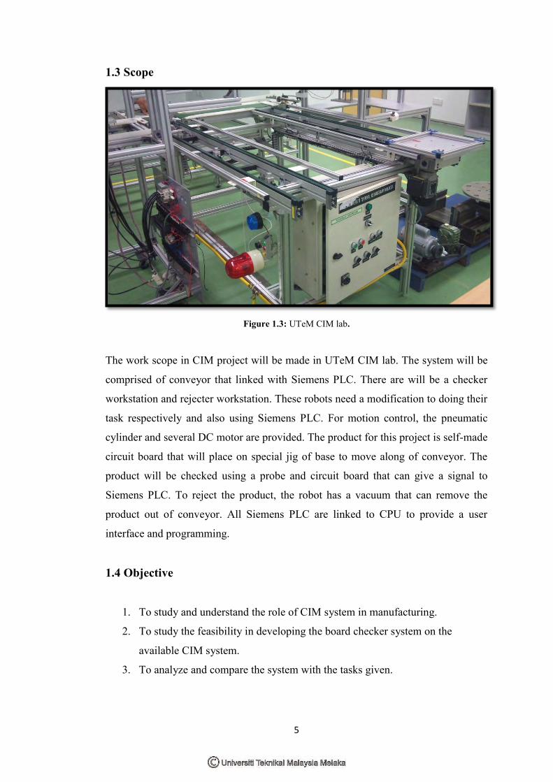
1.3 Scope
Figure 1.3: UTeM CIM lab.
The work scope in CIM project will be made in UTeM CIM lab. The system will be
comprised of conveyor that linked with Siemens PLC. There are will be a checker
workstation and rejecter workstation. These robots need a modification to doing their
task respectively and also using Siemens PLC. For motion control, the pneumatic
cylinder and several DC motor are provided. The product for this project is self-made
circuit board that will place on special jig of base to move along of conveyor. The
product will be checked using a probe and circuit board that can give a signal to
Siemens PLC. To reject the product, the robot has a vacuum that can remove the
product out of conveyor. All Siemens PLC are linked to CPU to provide a user
interface and programming.
1.4 Objective
1. To study and understand the role of CIM system in manufacturing.
2. To study the feasibility in developing the board checker system on the
available CIM system.
3. To analyze and compare the system with the tasks given.
Page 23
6
CHAPTER 2
LITERATURE REVIEW
A literature review is a body of text that aims to review the critical points of current
knowledge including substantive findings as well as theoretical and methodological
contributions to a particular topic. Literature reviews are secondary sources, and as
such, do not report any new or original experimental work.
Most often associated with academic-oriented literature, such as these, a literature
review usually precedes a research proposal and results section. Its ultimate goal is to
bring the reader up to date with current literature on a topic and forms the basis for
another goal, such as future research that may be needed in the area.
A well-structured literature review is characterized by a logical flow of ideas; current
and relevant references with consistent, appropriate referencing style; proper use of
terminology; and an unbiased and comprehensive view of the previous research on
the topic.
Page 24
7
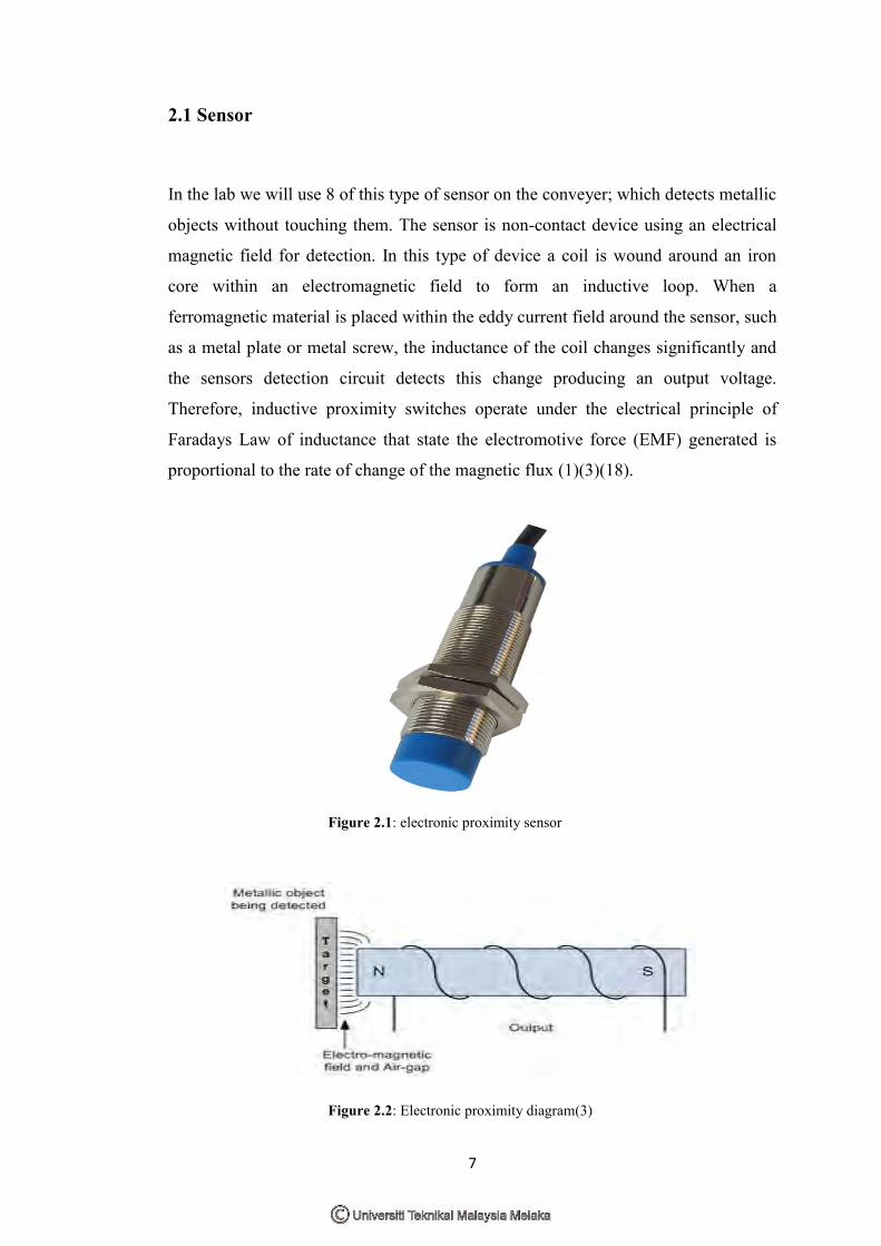
2.1 Sensor
In the lab we will use 8 of this type of sensor on the conveyer; which detects metallic
objects without touching them. The sensor is non-contact device using an electrical
magnetic field for detection. In this type of device a coil is wound around an iron
core within an electromagnetic field to form an inductive loop. When a
ferromagnetic material is placed within the eddy current field around the sensor, such
as a metal plate or metal screw, the inductance of the coil changes significantly and
the sensors detection circuit detects this change producing an output voltage.
Therefore, inductive proximity switches operate under the electrical principle of
Faradays Law of inductance that state the electromotive force (EMF) generated is
proportional to the rate of change of the magnetic flux (1)(3)(18).
Figure 2.1: electronic proximity sensor
Figure 2.2: Electronic proximity diagram(3)