Page 1
UNIVERSITI TEKNIKAL MALAYSIA MELAKA
PET FEEDING SYSTEM USING RASPBERRY PI AND GSM
This report is submitted in accordance with requirement of Universiti Teknikal
Malaysia Melaka (UTeM) for the Bachelor’s Degree of Electronic Engineering
Technology (Telecommunications) with Honours
by
CHAN WEI NICK
B071210113
921209-14-6737
FACULTY OF ENGINEERING TECHNOLOGY
2015
Page 2
UNIVERSITI TEKNIKAL MALAYSIA MELAKA
BORANG PENGESAHAN STATUS LAPORAN PROJEK SARJANA MUDA
TAJUK: Pet Feeding System Using Raspberry Pi and GSM
SESI PENGAJIAN: 2015/16 Semester 2
Saya CHAN WEI NICK
mengaku membenarkan Laporan PSM ini disimpan di Perpustakaan Universiti
Teknikal Malaysia Melaka (UTeM) dengan syarat-syarat kegunaan seperti berikut:
1. Laporan PSM adalah hak milik Universiti Teknikal Malaysia Melaka dan penulis. 2. Perpustakaan Universiti Teknikal Malaysia Melaka dibenarkan membuat salinan
untuk tujuan pengajian sahaja dengan izin penulis. 3. Perpustakaan dibenarkan membuat salinan laporan PSM ini sebagai bahan
pertukaran antara institusi pengajian tinggi.
4. **Sila tandakan ( )
SULIT
TERHAD
TIDAK TERHAD
(Mengandungi maklumat yang berdarjah keselamatan
atau kepentingan Malaysia sebagaimana yang termaktub
dalam AKTA RAHSIA RASMI 1972)
(Mengandungi maklumat TERHAD yang telah ditentukan
oleh organisasi/badan di mana penyelidikan dijalankan)
______________________________
Alamat Tetap:
95, JALAN 1/37B,
TAMAN BUKIT MALURI,
KEPONG, 52100, KL
Tarikh: 18th DECEMBER 2015
Disahkan oleh:
______________________________
Cop Rasmi:
Tarikh: _______________________
Page 3
iii
DECLARATION
I hereby, declare that this thesis entitled “Pet Feeding System using Raspberry Pi and
GSM” is the result of my own research except as cited in references.
Signature : ……………………………………………
Name : ……………………………………………
Date : ……………………………………………
Page 4
iv
APPROVAL
This report is submitted to the Faculty of Engineering Technology of UTeM as one
of the requirements for the award of Bachelor’s Degree of Electronic Engineering
Technology (Telecommunications) with Honours. The following are the members of
supervisory committee:
……………………………………………
(Supervisor)
Page 5
v
ABSTRACT
All pet owners have one common responsibility; to maintain their pet’s wellbeing
every day. One straight forward approach is to make sure that the pets are being fed
at regular intervals. Even so, the pet owners often find that even this simple
responsibility is hard to fulfil due to tons of reasons; even when they are around the
neighbourhood earning a living. The pet feeding system; generally known as the
automatic pet feeder, is introduced to counter this problem exactly, making both the
pet owners and their furry little companions happy. In this project, it introduces one
of the many applications of Raspberry Pi and GSM, combining the two makes an
automatic pet feeder with flexible feeding time plausible. With that said, this project
focuses mainly on the compatibility of Raspberry Pi and GSM by evaluating and
analysing their performances, and not evaluating the hardware components of the pet
feeder itself.
Page 6
vi
ABSTRAK
Pemilik-pemilik haiwan pemeliharaan mempunyai suatu responsibiliti yang sama;
memastikan haiwan kesayaang mereka sihat setiap hari. Bagi mengekalkan kesihatan
haiwan pemeliharaan mereka sihat, haiwan-haiwan wajib diberi makan dalam
tempoh masa yang tertentu. Walaubagaimanapun, bagi pemilik-pemilik yang
berkerja, mereka tiada cara penyelesaian yang berkesan bagi memberi makanan
kepada binatang pemiliharaan setiap hari. Tujuan Pet Feeding System diperkenalkan
adalah untuk mengatasi masalah pemakanan pemilik-pemilik binatang. Projek Pet
Feeding System ini mengunakan dua modal bernama Raspberry Pi dan GSM untuk
menghasilkan Pet Feeding System yang berfungsi dalam tempoh masa yang tidak
tetap. Pemilik haiwan kesayangan mempunyai peluang untuk memberi haiwan
kesayangan mereka makan bila-bila masa sahaja. Projek ini berfokus pada keserasian
Raspberry Pi dan GSM dengan menilai dan menganalisasi prestasi Raspberry Pi dan
GSM, dan tidak akan fokus kepada prestasi hardware komponen Pet Feeding System
ini.
Page 7
vii
DEDICATIONS
To my parents,
Chan Hooi Kee and Ong Guat Mooi
for raising me become who I am today.
Page 8
viii
ACKNOWLEDGEMENT
First and foremost, I would like to express my deepest gratitude to Mdm.
Norlezah binti Hashim for giving me an opportunity working under her supervision
throughout this project. Also to Mdm. Norain binti Rahim for taking up her place
when she’s not available during her leaves. The project would not be completed
under the time frame without their supervision.
Not forgetting the staffs of Faculty of Engineering Technology; my academic
advisor, Dr. Abdul Kadir for his professional advices in programming the system, lab
engineers for their assistance during my laboratory sessions, and also the other staffs
who had been helping me indirectly.
Special thanks to my peers, my friends to had been providing me remarkable
ideas to improve the project, my family who supported me physical, emotional, and
financial support throughout the project.
Page 9
ix
TABLE OF CONTENTS
DECLARATION ......................................................................................................... iii
APPROVAL ................................................................................................................. iv
ABSTRACT ................................................................................................................... v
ABSTRAK ................................................................................................................... vi
DEDICATIONS .......................................................................................................... vii
ACKNOWLEDGEMENT ......................................................................................... viii
TABLE OF CONTENTS ............................................................................................. ix
LIST OF TABLES ..................................................................................................... xiii
LIST OF FIGURES ................................................................................................... xiv
LIST OF ABBREVATIONS, SYMBOLS AND NOMENCLATURES .................. xvi
CHAPTER 1: INTRODUCTION ................................................................................. 1
1.1 Background ............................................................................................................. 1
1.2 Problem Statement .................................................................................................. 2
1.3 Objectives ............................................................................................................... 2
1.4 Project Scope and Limitations ................................................................................ 2
1.5 Project Significance ................................................................................................ 3
1.6 Summary ................................................................................................................. 3
CHAPTER 2: LITERATURE REVIEW ...................................................................... 4
2.1 Global System for Mobile Communications .......................................................... 4
Page 10
x
2.1.1 History of GSM .................................................................................................... 5
2.1.2 GSM Logical Architecture ................................................................................... 6
2.1.3 An Overview of SMS’s Operation ....................................................................... 9
2.1.4 Short Message Services provided by GSM ........................................................ 10
2.1.5 GSM Module (MOD-9001D GSM/GPRS Modem) ........................................... 10
2.2 Raspberry Pi .......................................................................................................... 11
2.2.1 History of Raspberry Pi ...................................................................................... 11
2.2.2 Raspberry Pi Model 2 B ..................................................................................... 12
2.2.3 Difference Between Different Raspberry Pi Models .......................................... 13
2.2.4 Raspberry Pi’s Connectors ................................................................................. 14
2.3 Past Related Researches ....................................................................................... 18
2.3.1 Raspberry Pi as Internet of Things Hardware..................................................... 18
2.3.2 Mobile Phone Controlled Farm Management Aider .......................................... 19
2.3.3 Automatic Pet Feeder with Wireless Sensing Network platform ....................... 20
2.3.4 Online DIY Timed Pet Feeder from Instructables .............................................. 21
2.4 Pet Feeding System ............................................................................................... 22
2.4.1 The Alternatives.................................................................................................. 22
2.4.2 Pet Feeding System from Different Companies ................................................. 24
2.4.3 Pet Owner’s Problems to be Overcame .............................................................. 26
2.5 Summary ............................................................................................................... 27
CHAPTER 3: METHODOLOGY .............................................................................. 28
Page 11
xi
3.1 Project Planning .................................................................................................... 28
3.2 Flowchart .............................................................................................................. 29
3.2.1 Project Research ................................................................................................. 31
3.2.2 Raspberry Pi and GSM Programming ................................................................ 31
3.2.3 Pet Feeding System Finalisation ......................................................................... 31
3.3 Block Diagram ...................................................................................................... 32
3.3.1 Block Diagram: Raspberry Pi ............................................................................. 32
3.3.2 Block Diagram: GSM Module (MOD-9001D) .................................................. 32
3.3.3 Block Diagram: Pet Feeder’s Valve ................................................................... 33
3.4 GSM Programming in Linux: gtkTerm ................................................................ 33
3.4.1 gtkTerm: AT commands ..................................................................................... 35
3.5 Raspberry Pi: New Out Of the Box Software (NOOBS) ..................................... 36
3.5.1 NOOBS: Raspbian Operating System ................................................................ 37
3.6 Raspberry Pi Programming: Python ..................................................................... 38
3.6.1 Python: time library ............................................................................................ 38
3.6.2 Python: RPi.GPIO library ................................................................................... 38
3.6.3 Python: py_serial library..................................................................................... 39
3.7 Project Hardware .................................................................................................. 39
3.7.1 Pet Feeder’s Valve .............................................................................................. 39
3.7.2 Communicating valve with Raspberry Pi ........................................................... 40
3.8 Summary ............................................................................................................... 41
Page 12
xii
CHAPTER 4: RESULTS AND DISCUSSIONS ....................................................... 42
4.1 Raspberry Pi and DC motor .................................................................................. 42
4.1.1 Specification of Raspberry Pi’s GPIO ................................................................ 42
4.1.2 Connecting DC motor directly to Raspberry Pi GPIO ....................................... 43
4.1.3 Connecting Relay with Raspberry Pi .................................................................. 44
4.2 Raspberry Pi and GSM Module 9001D ................................................................ 45
4.2.1 Exporting Log File .............................................................................................. 45
4.3 Time Delay ........................................................................................................... 46
4.3.1 Time Delay: Receiving SMS .............................................................................. 47
4.3.2 Time Delay: Rotating Valve ............................................................................... 47
4.4 Summary ............................................................................................................... 48
CHAPTER 5: CONCLUSION AND FUTURE WORK ............................................ 49
5.1 Conclusion ............................................................................................................ 49
5.2 Recommendations ................................................................................................. 50
APPENDIX A .............................................................................................................. 51
APPENDIX B .............................................................................................................. 53
APPENDIX C .............................................................................................................. 56
REFERENCES ............................................................................................................. 59
Page 13
xiii
LIST OF TABLES
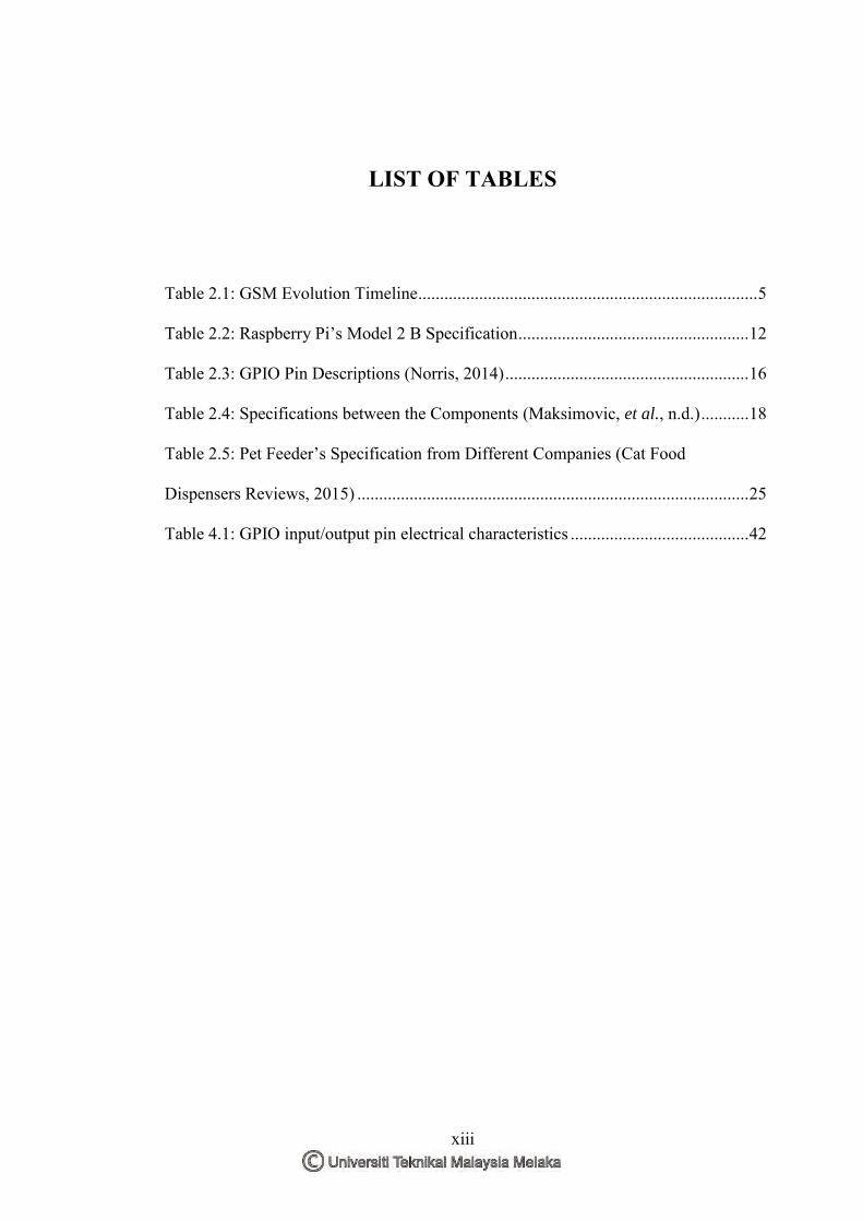
Table 2.1: GSM Evolution Timeline .............................................................................. 5
Table 2.2: Raspberry Pi’s Model 2 B Specification ..................................................... 12
Table 2.3: GPIO Pin Descriptions (Norris, 2014) ........................................................ 16
Table 2.4: Specifications between the Components (Maksimovic, et al., n.d.) ........... 18
Table 2.5: Pet Feeder’s Specification from Different Companies (Cat Food
Dispensers Reviews, 2015) .......................................................................................... 25
Table 4.1: GPIO input/output pin electrical characteristics ......................................... 42
Page 14
xiv
LIST OF FIGURES
Figure 2.1: Official Logo of GSM ................................................................................. 4
Figure 2.2: GSM Logical Architecture .......................................................................... 6
Figure 2.3: NSS and Its Environment ............................................................................ 8
Figure 2.4: Block Diagram of SMS Delivery ................................................................ 9
Figure 2.5: MOD-9001D GSM/GPRS Modem by Cytron Technologies .................... 10
Figure 2.6: Raspberry Pi Model 2B ............................................................................. 12
Figure 2.7: 5V micro USB Power Supply .................................................................... 14
Figure 2.8: Power Usage of Raspberry Pi (Liang, 2013) ............................................. 14
Figure 2.9: Pin Configuration of BMC2836 ................................................................ 15
Figure 2.10: Self-Powered USB Hub ........................................................................... 17
Figure 2.11: Farm Management Aider Block Diagram (Venkateswaran, et al., 2014)19
Figure 2.12: Automatic Pet Feeder .............................................................................. 20
Figure 2.13: Network Structure of WSN Pet Feeder ................................................... 20
Figure 2.14: Timed Pet Feeder with Arduino and Servo Motor (crazydeadmoth,
2010) ............................................................................................................................ 21
Figure 2.15: Self-replenishing Feeder by Microban .................................................... 22
Figure 2.16: Dog Boarding Malaysia’s Logo .............................................................. 23
Figure 2.17: Samples of Automatic Timed Feeders by Different Companies. ............ 24
Figure 3.1: Project Flowchart Part 1 ............................................................................ 29
Figure 3.2: Project Flowchart Part 2 ............................................................................ 30
Page 15
xv
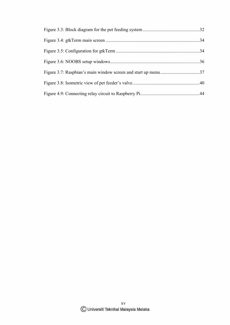
Figure 3.3: Block diagram for the pet feeding system ................................................. 32
Figure 3.4: gtkTerm main screen ................................................................................. 34
Figure 3.5: Configuration for gtkTerm ........................................................................ 34
Figure 3.6: NOOBS setup windows ............................................................................. 36
Figure 3.7: Raspbian’s main window screen and start up menu .................................. 37
Figure 3.8: Isometric view of pet feeder’s valve.......................................................... 40
Figure 4.9: Connecting relay circuit to Raspberry Pi ................................................... 44
Page 16
xvi
LIST OF ABBREVATIONS, SYMBOLS AND
NOMENCLATURES
A - Ampere
AC - Alternating Current
AuC - Authentication Centre
BSC - Base Station Controller
BSS - Base Station Subsystem
BTS - Base Transceiver Station
CEPT - European Conference of Postal and Telecommunications
DC - Direct Current
DTMF - Dual Tone Multi Frequency
EIR - Equipment Identity Register
ETSI - European Telecommunications Standards
GMSC - Gateway Mobile Switching Centre
GPIO - General Purpose Input Output
GPRS - General Packet Radio Service
GSM - Global System for Mobile Communication
HD - High Definition
HDMI - High Definition Multimedia Interface
HLR - Home Location Register
ME - Mobile Equipment
MMS - Multimedia Messaging Service
MOD - Module
MoU - Memorandum of Understanding
MS - Mobile Station
MSC - Mobile Switching Centre
NOOBS - New Out Of the Box Software
Page 17
xvii
NSS - Network and Switching Subsystem
OS - Operating System
OSI - Open System Interconnection
OSS - Operation Subsystem
PCB - Printed Circuit Board
PSTN - Public Switch Telephone Network
RSS - Radio Subsystem
SCM - Single Chip Micyoco
SIM - Subscriber’s Identity Module
SMS - Short Messaging Service
SMSC - Short Messaging Service Centre
SS7 - Signalling System No. 7
TCP/IP - Transmission Control Protocol/ Internet Protocol
TS-xx - Teleservices no. xx
USB - Universal Serial Bus
V - Volt
VLR - Visitor Location Register
Page 18
1
CHAPTER 1 INTRODUCTION
This chapter introduces the project with its background, problem statement,
objectives, scope and project significance, to provide a sense of purpose and reasons
to proceed with this project.
1.1 Background
Pet feeding system was introduced to compensate with the many excuses of
why “responsible pet owners” are hard to come by, especially when everybody is
spending most of their time out of their premise finding a living to sustain their
family. Raspberry Pi will be used in the system to function as its core; modules like
Global System for Mobile Communications (GSM) and sensors will be used to
provide inputs to the Raspberry Pi in order for the system to communicate with the
environment. The pet feeding system will then be tested with domestic pets to verify
the functionality and the flaw of the system itself.
Page 19
2
1.2 Problem Statement
Pet owners around the world are aware of that having a pet means having extra
commitment to provide the best care and support to them (Dog Boarding Malaysia,
2015). It is unfortunate that not all pet owners have the time or energy to provide
their pets’ basic needs such as food and water due to reasons like working and
travelling, sometimes both at the same time. This problem faced by the pet owners
may lead to unintentional animal abuse due to lack of feeding. Often the pet owners
find themselves troubling their friends and families to babysit their pet while they are
away, which may be inappropriate after some frequent requests. The pet feeding
system is designed to counter the problem that all pet owners are facing.
1.3 Objectives
The main objective of this research is deeply concentrated on aspect as listed below:
i. To analyse existing techniques available on long distance pet feeding
systems.
ii. To suggest, develop and implement a long distance pet feeding system
using Raspberry Pi and GSM.
iii. To evaluate and analyse the performance of the developed system.
1.4 Project Scope and Limitations
Project scope is a part of project planning that includes a list of goals,
deliverables and tasks (Rouse, 2015). This project involves in programming on
Raspberry Pi and GSM, along with testing on domestic pets on its functionalities and
its flaws.
Page 20
3
The pet feeding system produced needs both Raspberry Pi and GSM to
communicate with each other to perform the system’s desired task. A good
programming will allow the modules to send information to each other with
minimum delay.
The functionality of the pet feeding system will be verified by testing on
different domestic pets with the cooperation of neighbours who owns a pet. The
possible flaws of the system will also be verified at the time and improvements will
be made if possible.
Since the project focuses on the performances of Raspberry Pi and GSM, the
durability of the hardware itself will not be evaluated as much as the programming.
1.5 Project Significance
Living in the globalisation era, most of the people are spending most of their
time out of their home to earn a living for themselves. As stress takes a toll on our
life, a companion like a pet is needed to reduce part of the daily stress. It is such an
irony that, while a pet can provide what their owners needed, the owners themselves
are not able to provide them basic necessities such as food. The pet feeding system
will be able to help both pets and their owner happy. With the opportunity that
similar pet feeding systems are not common in Malaysia, this project will create
awareness to the pet owners’ of its feasibility and advantages it may provide in the
future.
1.6 Summary
In a nutshell, the pet feeding system uses Raspberry Pi and GSM along with
some sensors that will help the system to perform better. The purpose of this project
is to eliminate the problem that all pet owners are facing; feeding their pet while they
are unavailable like working or travelling.
Page 21
4
CHAPTER 2 LITERATURE REVIEW
This chapter provides understandings of theories and previous researches that
are related to this final year project. This includes an overview of GSM, the
specifications of Raspberry Pi, similar products from all kind of sources, and more.
2.1 Global System for Mobile Communications
Figure 2.1: Official Logo of GSM
Figure 2.1 illustrates the latest and official logo of GSM Corporation. Cellular
technology is one of the fastest growing telecommunication applications. Prior to
GSM, the cellular technology evolved so independently, it causes many problems
such as the compatibility of different technologies without the standardized
specifications. Hence GSM was founded to provide specifications that define the
function and interface of different technologies. The idea of GSM is to minimize the
limitation in technological design but still maintain a wide range of applications
(TelecomSpace, 2010).
Since then, GSM has been the most widely used and the most successful
communication system of all time, enabling over four billion subscribers to
Page 22
5
communicate with virtually everyone from every corner of the world (Saily, et al.,
2011).
2.1.1 History of GSM
Table 2.1 shows the timeline of GSM evolution throughout the history. In
1982, a standardization group, the Groupe Speciale Mobile (GSM) was started by
Conference for European Post and Telecommunications Administration (CEPT) in
order to formulate a specification of a common European telecommunication service
around 900 MHz for a mobile cellular radio system. This system introduces a new
opportunity for users to be able to use their phone anywhere within Europe at that
time.
Table 2.1: GSM Evolution Timeline
Year Description 1982 European Conference of Postal and Telecommunications Administrations
(CEPT) created the Groupe Speciale Mobile (GSM) to develop a standard for voice telephonies
1987 Europe produced the first GSM Technical Specification 1989 Groupe Speciale Mobile transferred to European Telecommunications
Standards Institute (ETSI) 1991 The first Short Messaging Service (SMS) was sent, GSM standard was
expanded to 1800 MHz frequency band 1993 Telecom Australia became the first network operator outside Europe to
implement a GSM network. 1995 New technologies like fax, data, and SMS messaging services were
launched commercially 1996 Prepaid GSM SIM cards were launched and the subscribers exceeded 10
million. 2000 GPRS services were launched commercially. GSM subscribers exceeded
500 million in this year. 2002 Multimedia Messaging Service (MMS) were introduced. 2005 75% of the worldwide cellular network uses GSM network and GSM
subscriber exceeded 1.5 billion subscribers.
Page 23
6
In 1987, the GSM Association had decided on a standard that combined the
best characteristics of different systems. At this time, 17 countries signed the
Memorandum of Understanding (MoU) committing themselves to fulfil the ‘GSM
specifications’ and confirmed their commitment to introducing mobile radio based
on the recommendations from GSM.
Later in March 1989, the GSM Association was taken over by European
Telecommunication Standard Institute (ETSI), and since 1991 has been called the
Special Mobile Group (SMG). Since then, the abbreviation of GSM stands for
Global System for Mobile Communication, thereby underlining its claim as a
worldwide standard (Stuckmann, 2003).
2.1.2 GSM Logical Architecture
Figure 2.2 is the GSM logical architecture by hierarchy. GSM specifies that
every technology is divided into the Radio Subsystem (RSS), the Network and
Switching Subsystem (NSS) and the Operation Subsystem (OSS). Each of these
systems contains an array of functions, where all system functions are combined
together. The functional units are then implemented in various form of equipment
uncontrolled by GSM themselves.
Figure 2.2: GSM Logical Architecture
ME
SIM
BTS
BSC
MSC
EIR AuC
HLR VLR
BTS
BSC
Mobile Station Base Station
Subsystem Network Subsystem
Page 24
7
2.1.2.1 The Mobile Station
A GSM Mobile Station (MS) consists of two parts. The first part contains all
the hardware and software components relating to the radio interface. The second
part, known as the Subscriber Identity Module (SIM), stores all subscribers’ personal
data. The SIM is either installed into the terminal or provided as a smart card, which
has the function of a key. Once it has been removed, the device can only be used for
emergency calls, with a requirement that the network coverage reaching that area. A
mobile subscriber can use the SIM to identify himself over any mobile station in the
network, and personalise their phone using the technology of SIM (Eberspacher, et
al., 2001).
2.1.2.2 Base Station Subsystem
The BSS is the connection between the Mobile Station (MS) and Network
Switching Subsystem (NSS) through a radio interface. The BSS comprises of a Base
Transceiver Station (BTS) and a Base Station Controller (BSC) that may control
several BTSs (Lee, 2006).
GSM uses the Open System Interconnection (OSI). There are three common
interfaces based on OSI namely air interface, interface A, and A-bis interface,
making the connection between MS and BTS, MSC and BSC, and BTS and BSC
respectively. The interface is important to connect different companies with different
protocols. Protocols and interfaces are different in a way that interface represents the
point of contact between two adjacent systems, and a protocol provides information
flows through the interface. In a simpler term, an interface is the transit point to
pertain several protocols (Lee, 2006).