32
Dr. Badreddine AYADI 2016 Design of springs Text Book : Mechanical Engineering Design, 9th Edition Chapter 10 UNIVERSITY OF HAIL College of Engineering Department of Mechanical Engineering

Dr. Badreddine AYADI
2016
Design of springs
Text Book : Mechanical Engineering Design, 9th Edition
Chapter 10
UNIVERSITY OF HAIL College of Engineering
Department of Mechanical Engineering

Chapter Outline
Introduction
Stresses in Helical Springs
The Curvature Effect
Deflection of Helical Springs
Compression Springs
Stability
Spring Materials
Helical Compression Spring Design for Static Service
Critical Frequency of Helical Springs
Fatigue Loading of Helical Compression Springs
Extension Springs
Helical Coil Torsion Springs
Slide 2 Design of springs
Slide 3 Design of springs
Introduction
Springs are Characterized By:
Ability to deform significantly without
failure.
Ability to store and release energy over
large deflections.
Provides an elastic force for useful
purpose.
Slide 4 Design of springs
How used in mechanical design?
Shock/Vibration protection
Store/Release PE
Offer resisting force or reaction force for mechanism
Example:
Torsion springs keeps door closed
Our focus will be on Helical Springs
Standard round wire wrapped into cylinder,
usually constant pitch.
We will cover design process and analysis.
Introduction
Slide 5 Design of springs
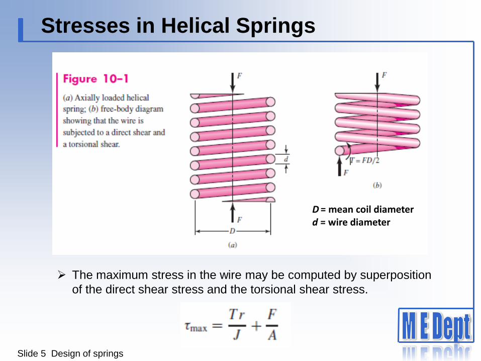
Stresses in Helical Springs
D = mean coil diameter d = wire diameter
The maximum stress in the wire may be computed by superposition
of the direct shear stress and the torsional shear stress.
Slide 6 Design of springs
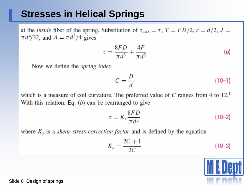
Stresses in Helical Springs
Slide 7 Design of springs
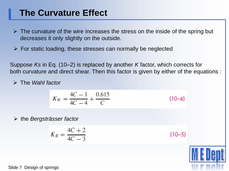
The Curvature Effect
The curvature of the wire increases the stress on the inside of the spring but
decreases it only slightly on the outside.
For static loading, these stresses can normally be neglected
Suppose Ks in Eq. (10–2) is replaced by another K factor, which corrects for
both curvature and direct shear. Then this factor is given by either of the equations :
The Wahl factor
the Bergsträsser factor

Slide 8 Design of springs
The Curvature Effect
The curvature correction factor can now be obtained by canceling out the effect of
the direct shear. Thus, using Eq. (10–5) with Eq. (10–3), the curvature correction
factor is found to be
Now, Ks , KB or KW , and Kc are simply stress-correction factors applied
multiplicatively to Tr/J at the critical location to estimate a particular stress.
There is no stress concentration factor. In this chapter we will use
to predict the largest shear stress.

Slide 9 Design of springs
Deflection of Helical Springs
The deflection-force relations are quite easily obtained by using Castigliano’s
theorem. The total strain energy for a helical spring is composed of a
torsional component and a shear component.
Substituting T = FD/2, l = πDN, J = πd4/32, and A = πd2/4 results in

Slide 10 Design of springs
Deflection of Helical Springs
Since C = D/d, Eq. (c) can be rearranged to yield
where N = Na = number of active coils. Then using Castigliano’s theorem,
to find total deflection y gives
The spring rate, also called the scale of the spring, is k = F/y, and so
Slide 11 Design of springs
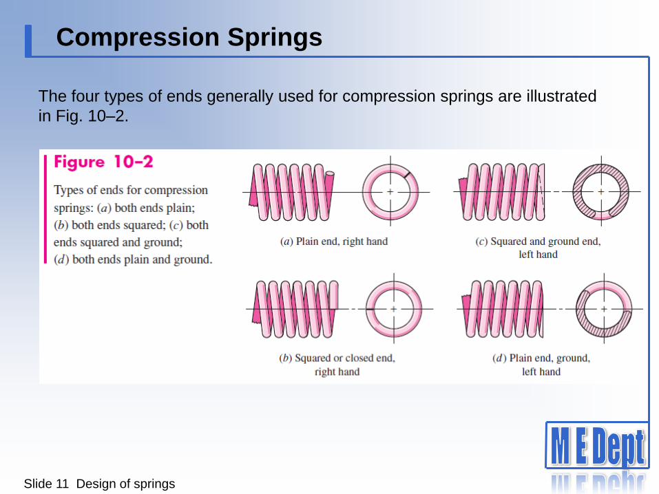
Compression Springs
The four types of ends generally used for compression springs are illustrated
in Fig. 10–2.
Slide 12 Design of springs
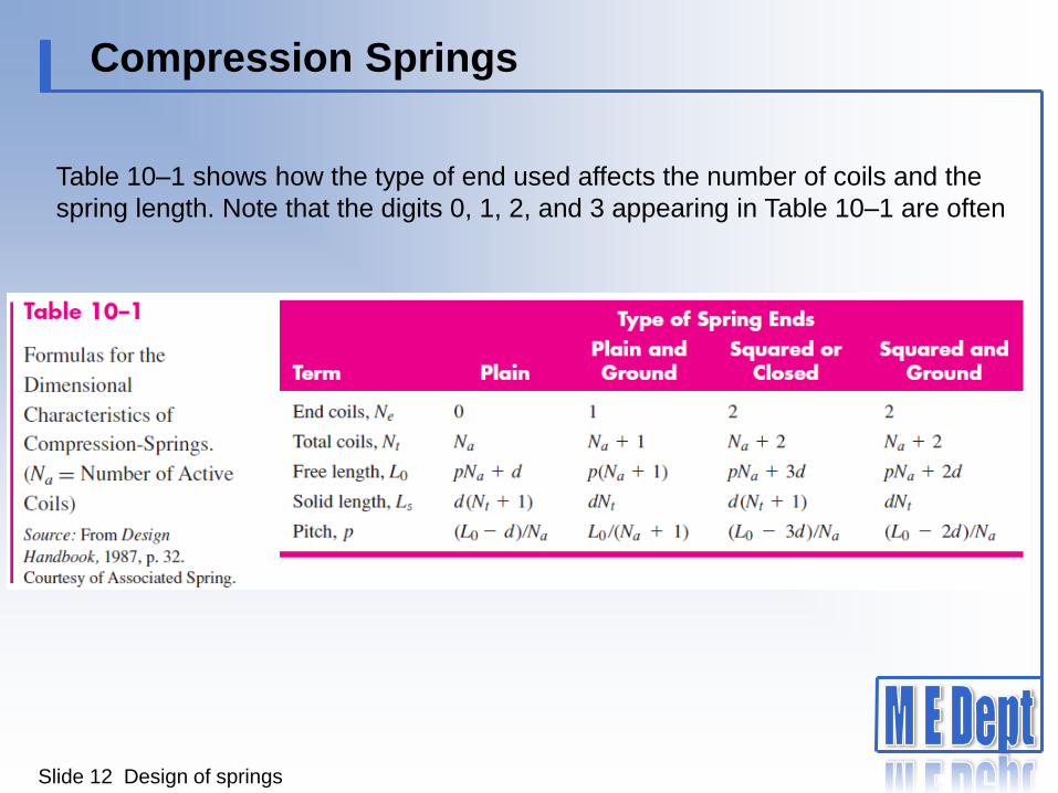
Compression Springs
Table 10–1 shows how the type of end used affects the number of coils and the
spring length. Note that the digits 0, 1, 2, and 3 appearing in Table 10–1 are often
Slide 13 Design of springs
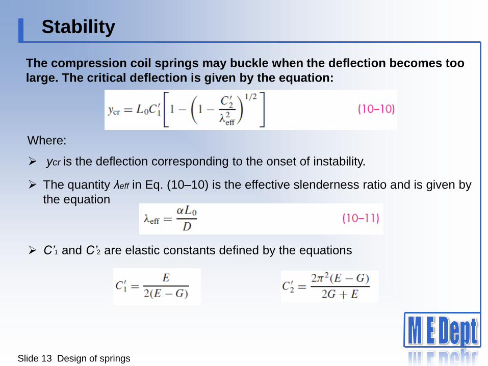
Stability
The compression coil springs may buckle when the deflection becomes too
large. The critical deflection is given by the equation:
Where:
The quantity λeff in Eq. (10–10) is the effective slenderness ratio and is given by
the equation
ycr is the deflection corresponding to the onset of instability.
C’1 and C’2 are elastic constants defined by the equations

Slide 14 Design of springs
Stability
Equation (10–11) contains the end-condition constant α. This depends upon how
the ends of the spring are supported. Table 10–2 gives values of α for usual end
conditions.
Absolute stability occurs when, in Eq. (10–10), the term C’2/λ2eff is greater than
unity. This means that the condition for absolute stability is that
For steels, this turns out to be
For squared and ground ends α = 0.5 and L0 < 5.26D.
Slide 15 Design of springs
Spring Materials
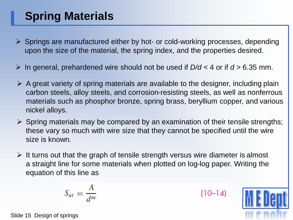
Springs are manufactured either by hot- or cold-working processes, depending
upon the size of the material, the spring index, and the properties desired.
In general, prehardened wire should not be used if D/d < 4 or if d > 6.35 mm.
A great variety of spring materials are available to the designer, including plain
carbon steels, alloy steels, and corrosion-resisting steels, as well as nonferrous
materials such as phosphor bronze, spring brass, beryllium copper, and various
nickel alloys.
Spring materials may be compared by an examination of their tensile strengths;
these vary so much with wire size that they cannot be specified until the wire
size is known.
It turns out that the graph of tensile strength versus wire diameter is almost
a straight line for some materials when plotted on log-log paper. Writing the
equation of this line as
Slide 16 Design of springs
Spring Materials
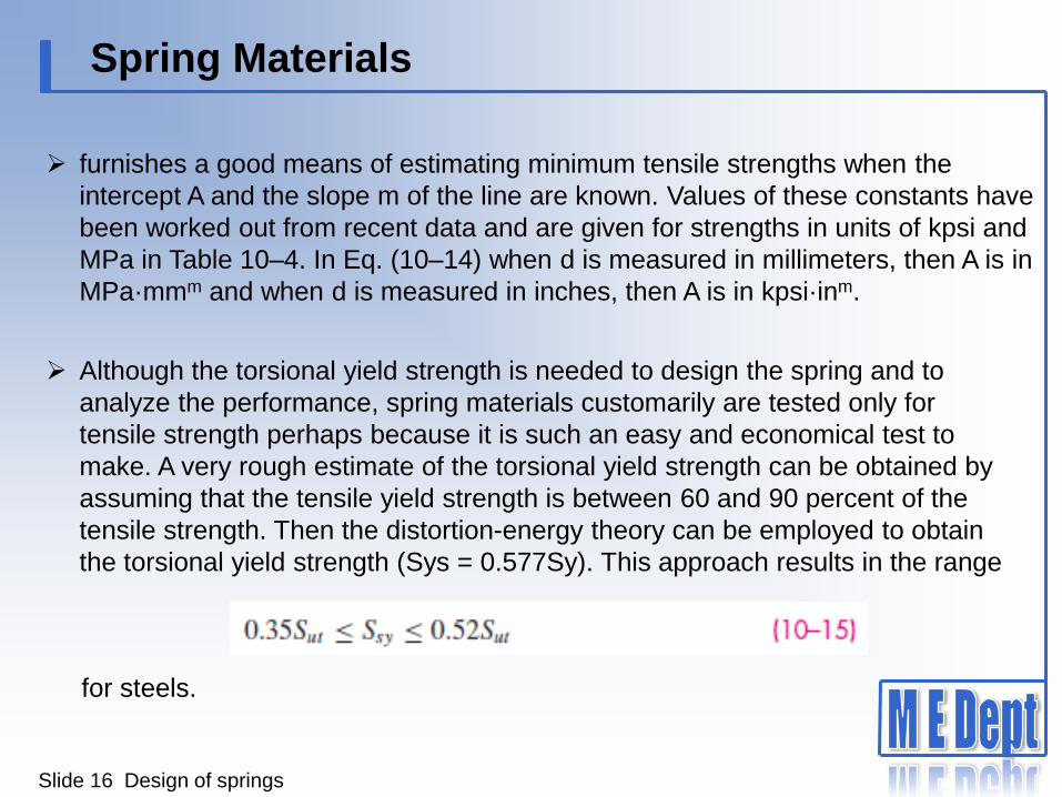
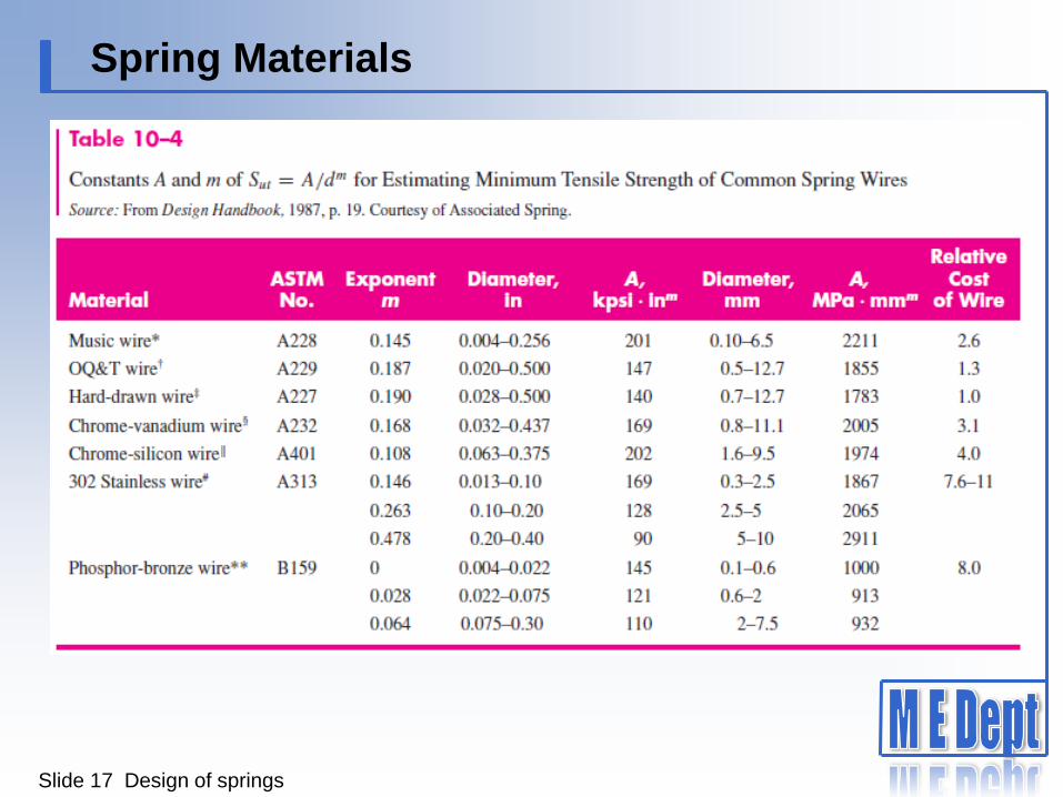
furnishes a good means of estimating minimum tensile strengths when the
intercept A and the slope m of the line are known. Values of these constants have
been worked out from recent data and are given for strengths in units of kpsi and
MPa in Table 10–4. In Eq. (10–14) when d is measured in millimeters, then A is in
MPa·mmm and when d is measured in inches, then A is in kpsi·inm.
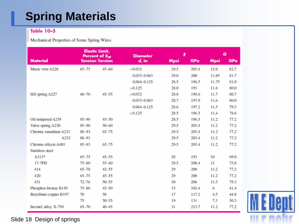
Although the torsional yield strength is needed to design the spring and to
analyze the performance, spring materials customarily are tested only for
tensile strength perhaps because it is such an easy and economical test to
make. A very rough estimate of the torsional yield strength can be obtained by
assuming that the tensile yield strength is between 60 and 90 percent of the
tensile strength. Then the distortion-energy theory can be employed to obtain
the torsional yield strength (Sys = 0.577Sy). This approach results in the range
for steels.
Slide 17 Design of springs
Spring Materials
Slide 18 Design of springs
Spring Materials

Slide 19 Design of springs
Spring Materials

EXAMPLE 10–1
Slide 20 Design of springs
A helical compression spring is made of no. 16 music wire. The outside coil
diameter of the spring is 11 mm. The ends are squared and there are 121
2
total turns.
(a) Estimate the torsional yield strength of the wire.
(b) Estimate the static load corresponding to the yield strength.
(c) Estimate the scale of the spring.
(d) Estimate the deflection that would be caused by the load in part (b).
(e) Estimate the solid length of the spring.
( f ) What length should the spring be to ensure that when it is compressed
solid and then released, there will be no permanent change in the free
length?
(g) Given the length found in part ( f ), is buckling a possibility?
(h) What is the pitch of the body coil?
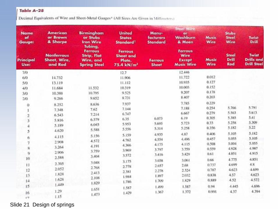
Slide 21 Design of springs
Helical Compression Spring Design for Static Service
Slide 22 Design of springs
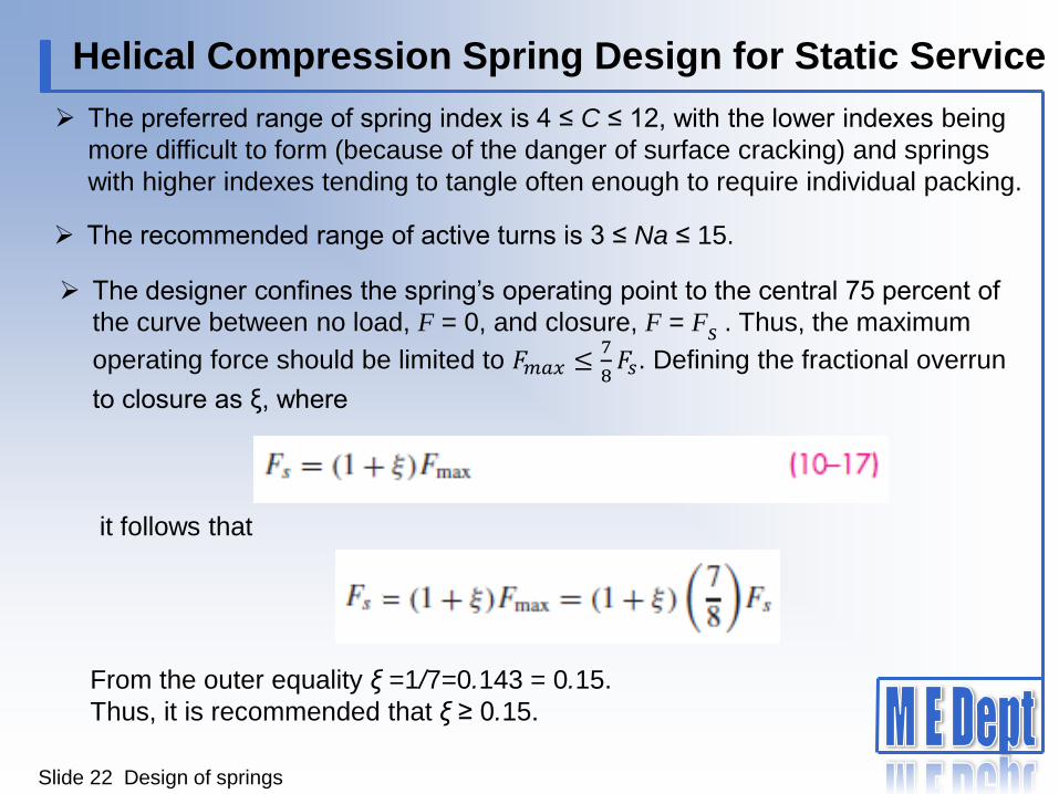
The preferred range of spring index is 4 ≤ C ≤ 12, with the lower indexes being
more difficult to form (because of the danger of surface cracking) and springs
with higher indexes tending to tangle often enough to require individual packing.
The recommended range of active turns is 3 ≤ Na ≤ 15.
The designer confines the spring’s operating point to the central 75 percent of
the curve between no load, F = 0, and closure, F = Fs . Thus, the maximum
operating force should be limited to 𝐹𝑚𝑎𝑥 ≤7
8𝐹𝑠. Defining the fractional overrun
to closure as ξ, where
it follows that
From the outer equality ξ =1/7=0.143 = 0.15.
Thus, it is recommended that ξ ≥ 0.15.

Slide 23 Design of springs
Helical Compression Spring Design for Static Service
In addition to the relationships and material properties for springs, we now have
some recommended design conditions to follow, namely:
where ns is the factor of safety at closure (solid height).
When considering designing a spring for high volume production, the figure of
merit (fom) can be the cost of the wire from which the spring is wound. The fom
would be proportional to the relative material cost, weight density, and volume:
Slide 24 Design of springs
Critical Frequency of Helical Springs
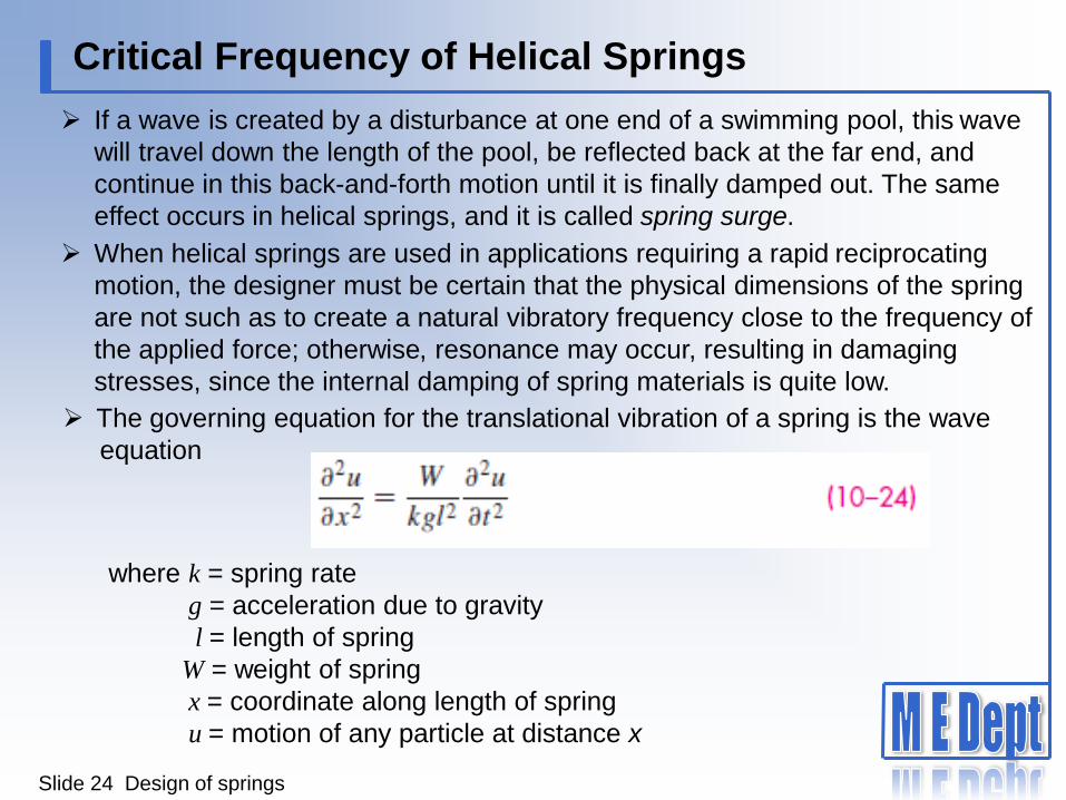
If a wave is created by a disturbance at one end of a swimming pool, this wave
will travel down the length of the pool, be reflected back at the far end, and
continue in this back-and-forth motion until it is finally damped out. The same
effect occurs in helical springs, and it is called spring surge.
When helical springs are used in applications requiring a rapid reciprocating
motion, the designer must be certain that the physical dimensions of the spring
are not such as to create a natural vibratory frequency close to the frequency of
the applied force; otherwise, resonance may occur, resulting in damaging
stresses, since the internal damping of spring materials is quite low.
The governing equation for the translational vibration of a spring is the wave
equation
where k = spring rate
g = acceleration due to gravity
l = length of spring
W = weight of spring
x = coordinate along length of spring
u = motion of any particle at distance x

Slide 25 Design of springs
Critical Frequency of Helical Springs
The solution to this equation is harmonic and depends on the given physical
properties as well as the end conditions of the spring. The harmonic, natural,
frequencies for a spring placed between two flat and parallel plates, in radians
per second, are
where the fundamental frequency is found for m = 1, the second harmonic for
m = 2, and so on. We are usually interested in the frequency in cycles per
second; since ω = 2π f , we have, for the fundamental frequency in hertz,
assuming the spring ends are always in contact with the plates. Wolford and
Smith show that the frequency is
The weight of the active part of a helical spring is

Slide 26 Design of springs
Fatigue Loading of Helical Compression Springs
Springs are almost always subject to fatigue loading. In many instances
the number of cycles of required life may be small, say, several thousand
for a padlock spring or a toggle-switch spring. But the valve spring of an
automotive engine must sustain millions of cycles of operation without
failure; so it must be designed for infinite life.
To improve the fatigue strength of dynamically loaded springs, shot
peening can be used. It can increase the torsional fatigue strength by 20
percent or more. Shot size is about 0.4 mm, so spring coil wire diameter
and pitch must allow for complete coverage of the spring surface.
Slide 27 Design of springs
Fatigue Loading of Helical Compression Springs
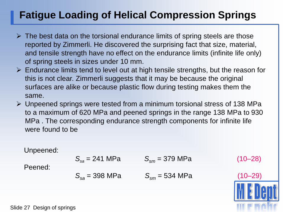
The best data on the torsional endurance limits of spring steels are those
reported by Zimmerli. He discovered the surprising fact that size, material,
and tensile strength have no effect on the endurance limits (infinite life only)
of spring steels in sizes under 10 mm.
Endurance limits tend to level out at high tensile strengths, but the reason for
this is not clear. Zimmerli suggests that it may be because the original
surfaces are alike or because plastic flow during testing makes them the
same.
Unpeened springs were tested from a minimum torsional stress of 138 MPa
to a maximum of 620 MPa and peened springs in the range 138 MPa to 930
MPa . The corresponding endurance strength components for infinite life
were found to be
Unpeened:
Ssa = 241 MPa Ssm = 379 MPa (10–28)
Peened:
Ssa = 398 MPa Ssm = 534 MPa (10–29)
Slide 28 Design of springs
Fatigue Loading of Helical Compression Springs
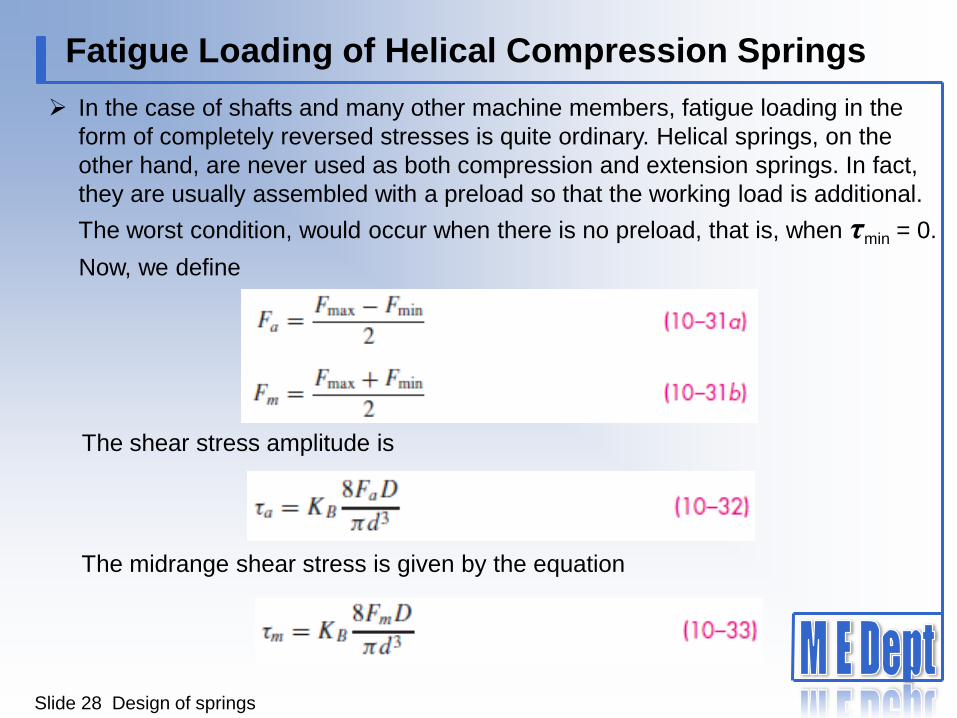
In the case of shafts and many other machine members, fatigue loading in the
form of completely reversed stresses is quite ordinary. Helical springs, on the
other hand, are never used as both compression and extension springs. In fact,
they are usually assembled with a preload so that the working load is additional.
The worst condition, would occur when there is no preload, that is, when τmin = 0.
Now, we define
The shear stress amplitude is
The midrange shear stress is given by the equation

Slide 29 Design of springs
Extension Springs
Extension springs differ from compression springs in that they carry tensile
loading, they require some means of transferring the load from the support to
the body of the spring, and the spring body is wound with an initial tension. The
load transfer can be done with a threaded plug or a swivel hook; both of these
add to the cost of the finished product.
Stresses in the body of the extension spring are handled the same as
compression springs. In designing a spring with a hook end, bending and
torsion in the hook

Slide 30 Design of springs
Extension Springs
Note: Radius r1 is in
the plane of the end
coil for curved beam
bending stress.
Radius r2 is at a
right angle to the
end coil for torsional
shear stress.
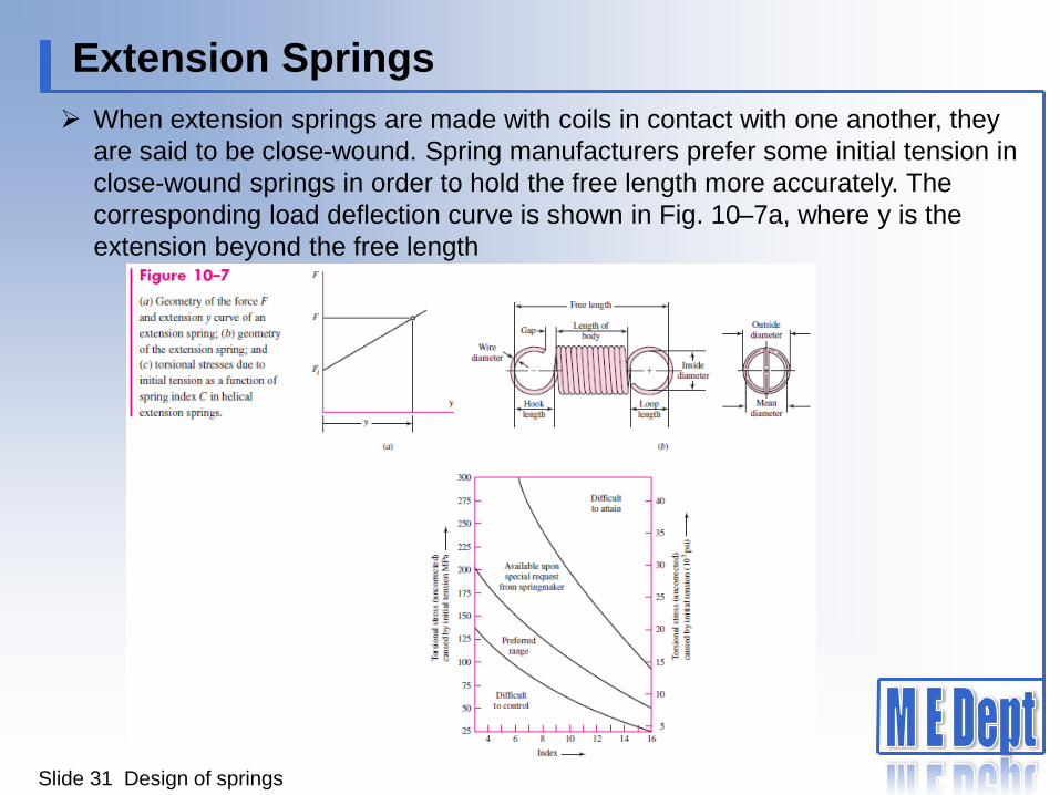
When extension springs are made with coils in contact with one another, they
are said to be close-wound. Spring manufacturers prefer some initial tension in
close-wound springs in order to hold the free length more accurately. The
corresponding load deflection curve is shown in Fig. 10–7a, where y is the
extension beyond the free length
Extension Springs
Slide 31 Design of springs
Helical Coil Torsion Springs
Slide 32 Design of springs
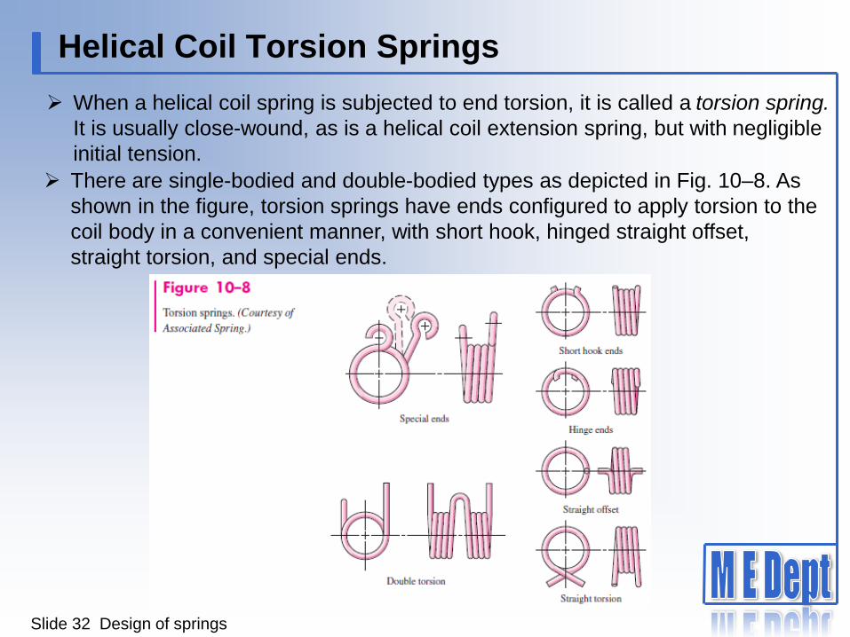
When a helical coil spring is subjected to end torsion, it is called a torsion spring.
It is usually close-wound, as is a helical coil extension spring, but with negligible
initial tension.
There are single-bodied and double-bodied types as depicted in Fig. 10–8. As
shown in the figure, torsion springs have ends configured to apply torsion to the
coil body in a convenient manner, with short hook, hinged straight offset,
straight torsion, and special ends.


![Ondulé: Designing and Controlling 3D Printable Springs · HELICAL SPRING THEORY Our approach is based on helical springs [22], which have three basic configurations—compression,](https://static.documents.pub/doc/80x56/5e97e6d886fa3e4f6f1a5e42/ondul-designing-and-controlling-3d-printable-helical-spring-theory-our-approach.jpg)


