University of Birmingham High speed imaging of biofilm removal from a dental implant model using ultrasonic cavitation Vyas, Nina; Grewal, Meher ; Kuehne, Sarah; Sammons, Rachel; Walmsley, Damian DOI: 10.1016/j.dental.2020.03.003 License: Creative Commons: Attribution-NonCommercial-NoDerivs (CC BY-NC-ND) Document Version Peer reviewed version Citation for published version (Harvard): Vyas, N, Grewal, M, Kuehne, S, Sammons, R & Walmsley, D 2020, 'High speed imaging of biofilm removal from a dental implant model using ultrasonic cavitation', Dental Materials, vol. 36, no. 6, pp. 733-743. https://doi.org/10.1016/j.dental.2020.03.003 Link to publication on Research at Birmingham portal General rights Unless a licence is specified above, all rights (including copyright and moral rights) in this document are retained by the authors and/or the copyright holders. The express permission of the copyright holder must be obtained for any use of this material other than for purposes permitted by law. • Users may freely distribute the URL that is used to identify this publication. • Users may download and/or print one copy of the publication from the University of Birmingham research portal for the purpose of private study or non-commercial research. • User may use extracts from the document in line with the concept of ‘fair dealing’ under the Copyright, Designs and Patents Act 1988 (?) • Users may not further distribute the material nor use it for the purposes of commercial gain. Where a licence is displayed above, please note the terms and conditions of the licence govern your use of this document. When citing, please reference the published version. Take down policy While the University of Birmingham exercises care and attention in making items available there are rare occasions when an item has been uploaded in error or has been deemed to be commercially or otherwise sensitive. If you believe that this is the case for this document, please contact [email protected] providing details and we will remove access to the work immediately and investigate. Download date: 04. Oct. 2021
Transcript
University of Birmingham
High speed imaging of biofilm removal from adental implant model using ultrasonic cavitationVyas, Nina; Grewal, Meher ; Kuehne, Sarah; Sammons, Rachel; Walmsley, Damian
Citation for published version (Harvard):Vyas, N, Grewal, M, Kuehne, S, Sammons, R & Walmsley, D 2020, 'High speed imaging of biofilm removal froma dental implant model using ultrasonic cavitation', Dental Materials, vol. 36, no. 6, pp. 733-743.https://doi.org/10.1016/j.dental.2020.03.003
Link to publication on Research at Birmingham portal
General rightsUnless a licence is specified above, all rights (including copyright and moral rights) in this document are retained by the authors and/or thecopyright holders. The express permission of the copyright holder must be obtained for any use of this material other than for purposespermitted by law.
•Users may freely distribute the URL that is used to identify this publication.•Users may download and/or print one copy of the publication from the University of Birmingham research portal for the purpose of privatestudy or non-commercial research.•User may use extracts from the document in line with the concept of ‘fair dealing’ under the Copyright, Designs and Patents Act 1988 (?)•Users may not further distribute the material nor use it for the purposes of commercial gain.
Where a licence is displayed above, please note the terms and conditions of the licence govern your use of this document.
When citing, please reference the published version.
Take down policyWhile the University of Birmingham exercises care and attention in making items available there are rare occasions when an item has beenuploaded in error or has been deemed to be commercially or otherwise sensitive.
If you believe that this is the case for this document, please contact [email protected] providing details and we will remove access tothe work immediately and investigate.
Millions of dental implants are fitted each year [1] and they require professional care to
maintain the health of the perimplant tissues. Maintenance of dental implants is required
to treat and prevent peri-implantitis and implant failure [2]. There is a high prevalence of
peri-implant disease which is often associated with bacterial infection [3, 4] and with the
number of dental implants increasing, it is imperative that the biofilm build-up around them
is removed effectively.
There is uncertainty about which is the most effective treatment for peri-implantitis [5, 6].
Surfaces are modified to promote osseointegration of the implant in the bone [7], but the
presence of biofilm and its accumulation around implants often leads to peri-implantitis and
bone loss [1]. This can lead to the roughened surfaces becoming exposed to the oral
environment, allowing further biofilm to accumulate. These surfaces can be easily damaged
by manual curettes or ultrasonic scaler tips which are used for periodontal therapy on teeth
[8-10]. Other techniques such as titanium or plastic scaler tips do not effectively clean these
implants, because they cannot clean in between the implant grooves and on the micro
rough surface [8, 11]. Therefore, research is being done into finding more effective implant
debridement methods [10, 12, 13].
A novel technique that could be used to remove biofilm from implants without causing
damage is the use of cavitation bubbles [14]. Acoustic cavitation is the growth and collapse
of microbubbles when exposed to an ultrasonic field [15]. They can disrupt bacterial biofilm
by collapsing and releasing shear forces through various cavitation phenomena such as
micro jet impingement and microstreaming [16]. Cavitation occurs around ultrasonic scalers
in the cooling water flowing over the vibrating tip [17] and it is being researched as a novel
method of biofilm removal which could clean dental implants without causing damage. Due
to the small size of cavitation bubbles, they may be able to reach under implant grooves, as
well as clean rough surfaces at the microscopic level. They also do not lead to any
detectable alteration of the implant surface [18] which could prevent increased biofilm
(re)growth and could help in re-osseointegration after peri-implantitis.
In order to understand how cavitation is able to remove biofilm from dental implants, real
time imaging of the cleaning process is required to visualise the bubble dynamics and
cleaning patterns. A high speed camera has been used in previous studies to image
cavitation bubbles around dental instruments [18-20]. It also has potential to be used as a
tool to evaluate biofilm disruption methods. However, there has been no detailed
investigation involving imaging of biofilm disruption occurring in real time on dental
implants in a more clinically accurate, confined space model.
Therefore there are two aims of this study:
1. To investigate if biofilm removal can be imaged in a novel way in real time from a
dental implant model in a confined space in vitro
2. To understand how cavitation from an ultrasonic scaler removes biofilm from an
implant in a restricted pocket model
Experiments were done using high speed imaging, scanning electron microscopy and image
analysis, on Strepotococcus sanguinis biofilms, which is an early coloniser on dental implant
surfaces.
2. Materials and Methods
2.1 Restricted pocket model
The implants used in this study were Xive S Plus D 4.5/L8-13 implants (supplied by Dentsply
Friadent, Mannheim Germany (now Dentsply Sirona) with a surface resembling the ‘Friadent
plus’ surface which is sand blasted and acid etched [21]. The implants have evenly spaced
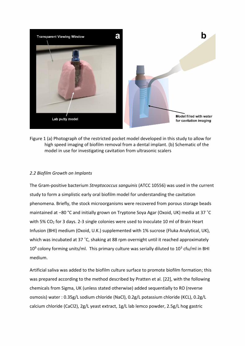
threads approximately 0.6 mm apart. A restricted pocket model was constructed (Figure 10)
using lab putty by creating an impression of the implant in a block of activated lab putty and
removing it before waiting for the lab putty to set. A section of the model was removed
using a scalpel to make a vertical cut for the viewing window. A plastic coverslip
(Thermanox™, 24 x 30mm, Nunc, ThermoFisher) was attached to the putty model to seal
and form the viewing window for high speed imaging.
Figure 1 (a) Photograph of the restricted pocket model developed in this study to allow for high speed imaging of biofilm removal from a dental implant. (b) Schematic of the model in use for investigating cavitation from ultrasonic scalers
2.2 Biofilm Growth on Implants
The Gram-positive bacterium Streptococcus sanguinis (ATCC 10556) was used in the current
study to form a simplistic early oral biofilm model for understanding the cavitation
phenomena. Briefly, the stock microorganisms were recovered from porous storage beads
maintained at −80 °C and initially grown on Tryptone Soya Agar (Oxoid, UK) media at 37 ˚C
with 5% CO2 for 3 days. 2-3 single colonies were used to inoculate 10 ml of Brain Heart
Infusion (BHI) medium (Oxoid, U.K.) supplemented with 1% sucrose (Fluka Analytical, UK),
which was incubated at 37 ˚C, shaking at 88 rpm overnight until it reached approximately
109 colony forming units/ml. This primary culture was serially diluted to 103 cfu/ml in BHI
medium.
Artificial saliva was added to the biofilm culture surface to promote biofilm formation; this
was prepared according to the method described by Pratten et al. [22], with the following
chemicals from Sigma, UK (unless stated otherwise) added sequentially to RO (reverse
mucin and 5g/L proteose peptone. Reagents were mixed on a magnetic stir plate (Fisher
scientific, Loughborough, UK) at ambient temperature for 1 hour. After autoclaving 1.25 mL
of 40% sterile filtered urea (0.22 µm filter) was added to 1 L of the prepared artificial saliva.
The prepared media was wrapped with aluminium foil to exclude light and prevent protein
degradation [23] before being stored at 4 ±1 °C. 2 ml of the artificial saliva was pipetted into
each well of a 24-well plate into which a sterile dental implant had been placed and was
removed after 15 minutes, to condition the samples.
Two ml of the diluted S. sanguinis culture was added to each well of the 24-well plates. The
24-well plates were then incubated at 37 ˚C, 88 rpm for 168h to allow biofilm formation.
The broth was replaced with 2 ml fresh BHI medium every 24 h. The dental implants were
removed from the 24 well plates after a total of 7 days of incubation and then fixed in 0.1 M
sodium cacodylate buffer and 2.5% glutaraldehyde (25% EM grade, Agar Scientific, Essex,
UK). They were then stained with 0.1% Crystal Violet stain (Pro-Lab Diagnostics, UK) for 5
minutes and gently washed in Phosphate Buffered Saline (PBS) (Sigma-Aldrich, USA).
Samples were stored in PBS at room temperature until high speed imaging to prevent
dehydration.
2.3 High speed imaging
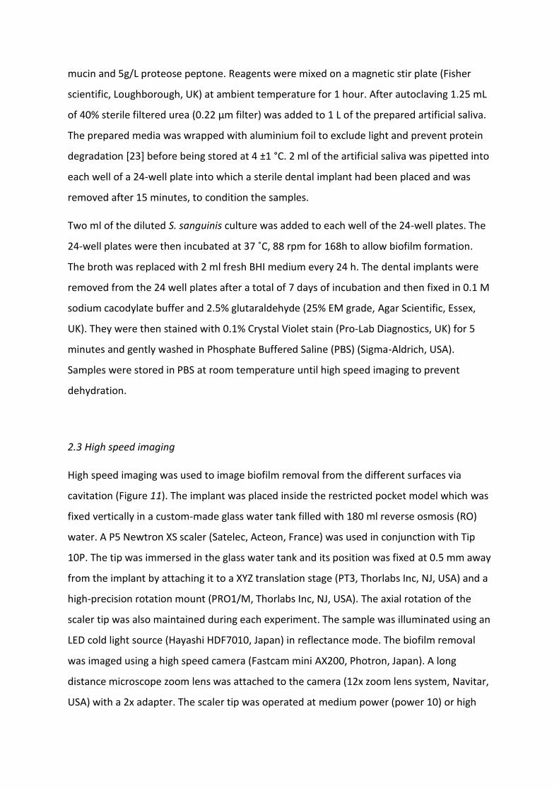
High speed imaging was used to image biofilm removal from the different surfaces via
cavitation (Figure 11). The implant was placed inside the restricted pocket model which was
fixed vertically in a custom-made glass water tank filled with 180 ml reverse osmosis (RO)
water. A P5 Newtron XS scaler (Satelec, Acteon, France) was used in conjunction with Tip
10P. The tip was immersed in the glass water tank and its position was fixed at 0.5 mm away
from the implant by attaching it to a XYZ translation stage (PT3, Thorlabs Inc, NJ, USA) and a
high-precision rotation mount (PRO1/M, Thorlabs Inc, NJ, USA). The axial rotation of the
scaler tip was also maintained during each experiment. The sample was illuminated using an
LED cold light source (Hayashi HDF7010, Japan) in reflectance mode. The biofilm removal
was imaged using a high speed camera (Fastcam mini AX200, Photron, Japan). A long
distance microscope zoom lens was attached to the camera (12x zoom lens system, Navitar,
USA) with a 2x adapter. The scaler tip was operated at medium power (power 10) or high
power (power 20) for 2s. Five samples were imaged for each test condition. High speed
imaging was done at 500 frames per second (fps), with a shutter speed of 1/1000 s, at a
magnification of x0.8 or x4 giving a resolution of 12.5 µm/pixel or 2.5 µm/pixel respectively.
Figure 2 Schematic of the high speed imaging setup
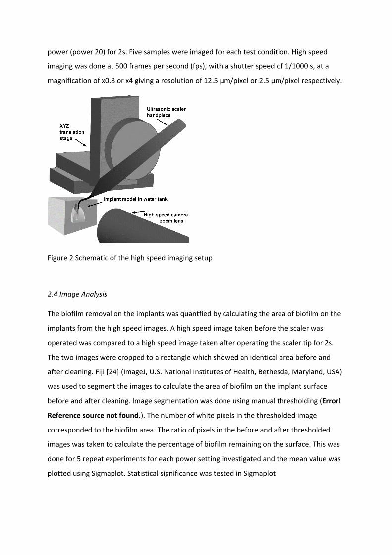
2.4 Image Analysis
The biofilm removal on the implants was quantfied by calculating the area of biofilm on the
implants from the high speed images. A high speed image taken before the scaler was
operated was compared to a high speed image taken after operating the scaler tip for 2s.
The two images were cropped to a rectangle which showed an identical area before and
after cleaning. Fiji [24] (ImageJ, U.S. National Institutes of Health, Bethesda, Maryland, USA)
was used to segment the images to calculate the area of biofilm on the implant surface
before and after cleaning. Image segmentation was done using manual thresholding (Error!
Reference source not found.). The number of white pixels in the thresholded image
corresponded to the biofilm area. The ratio of pixels in the before and after thresholded
images was taken to calculate the percentage of biofilm remaining on the surface. This was
done for 5 repeat experiments for each power setting investigated and the mean value was
plotted using Sigmaplot. Statistical significance was tested in Sigmaplot
Figure 3 Image analysis steps on an example high speed image showing how the image was cropped (b) and thresholded (c). The blue overlay (d) of the thresholded image on the original image demonstrates the accuracy of the image segmentation
2.5 Scanning Electron Microscopy
Scanning electron microscopy (SEM) was used to image the implants at high magnification
before biofilm growth and after the biofilm disruption experiments using an EVO MA-10
(Zeiss, Germany). Images were taken at x2000 and x5000 magnification, at a working
distance of 11 mm and 10 kV. Samples were dehydrated using serial ethanol gradient
immersions and then gold sputter-coated (Emitech K550X, Kent, UK) for SEM as previously
described [25]. For imaging after cleaning, images were taken at the point where the tip of
the ultrasonic scaler tip was closest to the implant (between the 5th and 6th threads, counted
from the top) and also towards the top of the implant between the 1st and 2nd threads.
3. Results
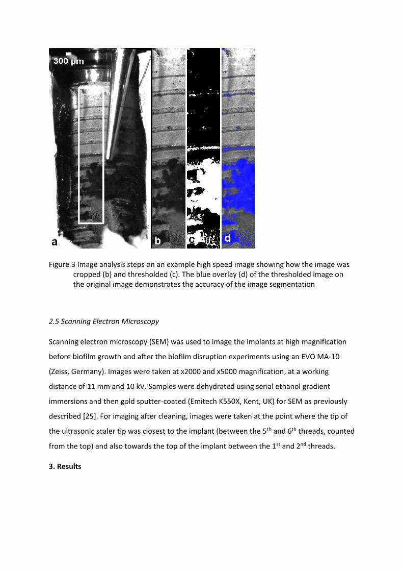
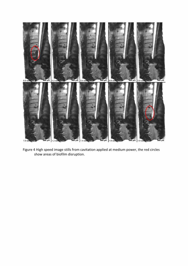
Figure 4 High speed image stills from cavitation applied at medium power, the red circles show areas of biofilm disruption.
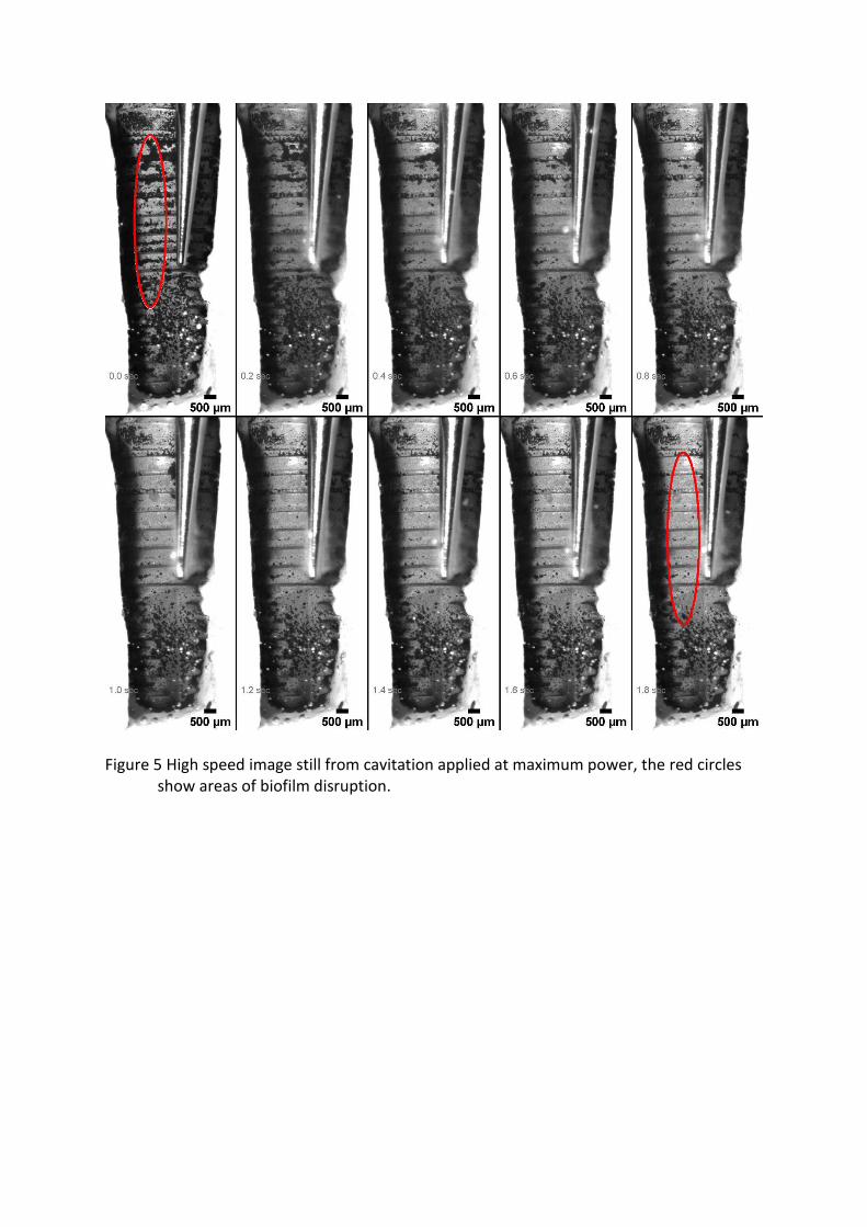
Figure 5 High speed image still from cavitation applied at maximum power, the red circles show areas of biofilm disruption.
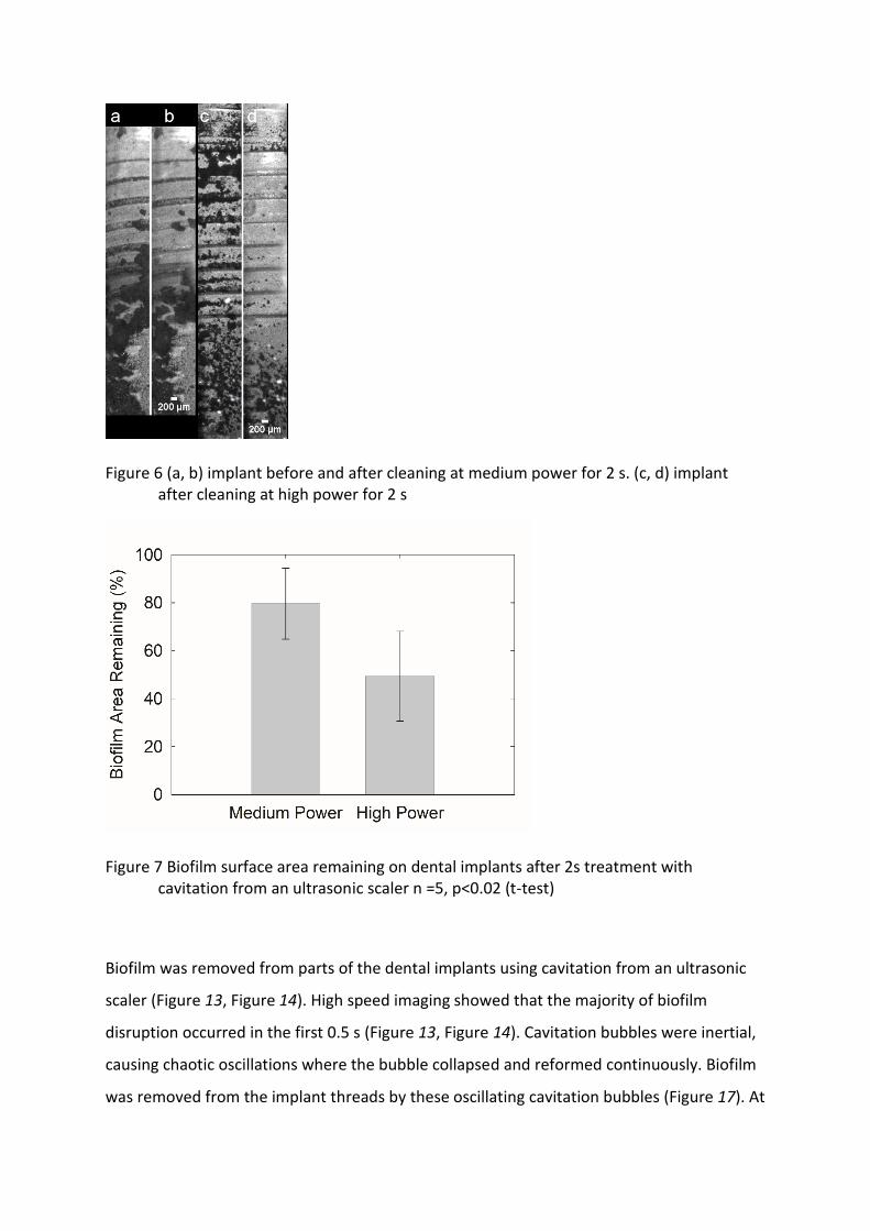
Figure 6 (a, b) implant before and after cleaning at medium power for 2 s. (c, d) implant after cleaning at high power for 2 s
Figure 7 Biofilm surface area remaining on dental implants after 2s treatment with cavitation from an ultrasonic scaler n =5, p<0.02 (t-test)
Biofilm was removed from parts of the dental implants using cavitation from an ultrasonic
scaler (Figure 13, Figure 14). High speed imaging showed that the majority of biofilm
disruption occurred in the first 0.5 s (Figure 13, Figure 14). Cavitation bubbles were inertial,
causing chaotic oscillations where the bubble collapsed and reformed continuously. Biofilm
was removed from the implant threads by these oscillating cavitation bubbles (Figure 17). At
power 10 small cavitation bubbles between 20-50µm in diameter appeared to be seen on
the implant surface (supplementary video). Larger bubble clusters were also seen with
diameters between 100-200 µm. At maximum power these bubble clusters were larger,
with diameters between 200-500µm (Figure 17). The implant grooves were evenly spaced,
but bacterial biofilm formed irregularly on the implants, either in between the grooves or on
raised surfaces. In some cases the biofilm formed in clusters with loosely attached biofilm
streamers, whereas in other cases it formed in thin, long strips running parallel to the
implant threads (supplementary videos). Both types of biofilm were removed via cavitation,
although only in certain locations on the implant.
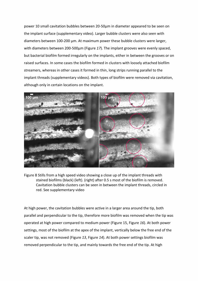
Figure 8 Stills from a high speed video showing a close up of the implant threads with stained biofilms (black) (left). (right) after 0.5 s most of the biofilm is removed. Cavitation bubble clusters can be seen in between the implant threads, circled in red. See supplementary video
At high power, the cavitation bubbles were active in a larger area around the tip, both
parallel and perpendicular to the tip, therefore more biofilm was removed when the tip was
operated at high power compared to medium power (Figure 15, Figure 16). At both power
settings, most of the biofilm at the apex of the implant, vertically below the free end of the
scaler tip, was not removed (Figure 13, Figure 14). At both power settings biofilm was
removed perpendicular to the tip, and mainly towards the free end of the tip. At high
power, some biofilm was also removed towards the implant abutment, which did not
happen at medium power (supplementary videos).
At high power the diameter of the cavitation bubbles was similar to the width of the implant
threads (Figure 17). The bubbles travelled horizontally inside the threads and caused most
of the biofilm disruption. Biofilm streamers, which are loosely attached parts at the top of a
biofilm cluster, were removed first. In some cases smaller biofilm structures which were
closer to the implant surface were not removed even after the cavitation bubble clusters
made contact with them multiple times. This was seen at both medium and high power.
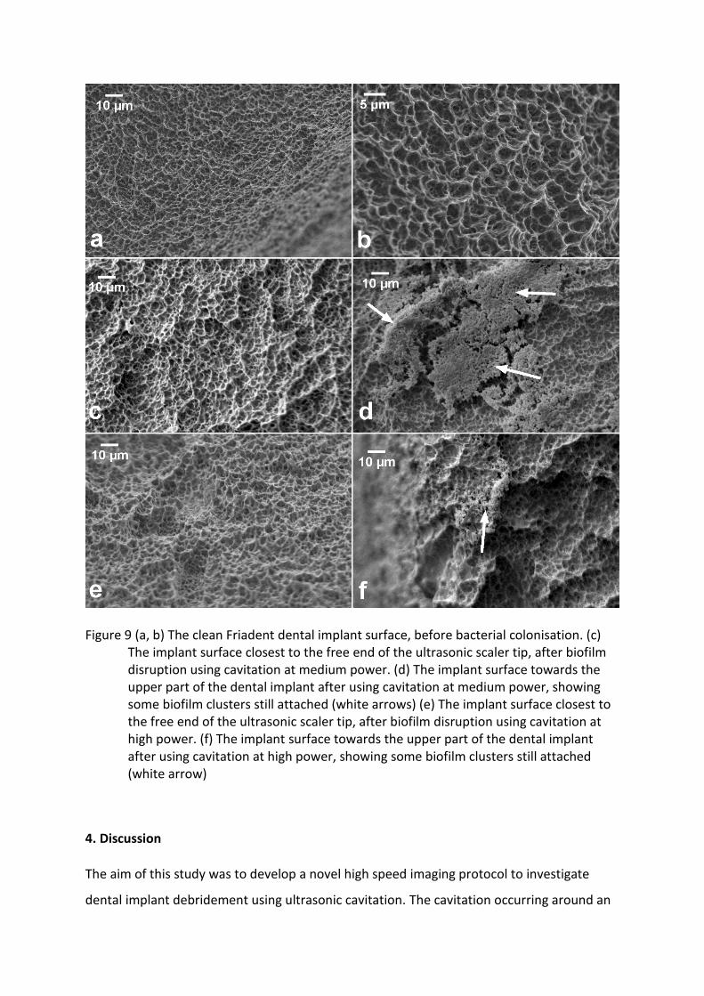
Scanning electron microscopy images showed that the implant surface was returned to its
original condition at locations where the free end of the ultrasonic scaler tip was closest to
the implant (Figure 18). This was the case when cavitation was used at both medium and
high power. However small clusters of biofilm were found still attached to the implant
surface towards the top of the implant, for both power settings, although more biofilm
remained when medium power was used.
Figure 9 (a, b) The clean Friadent dental implant surface, before bacterial colonisation. (c) The implant surface closest to the free end of the ultrasonic scaler tip, after biofilm disruption using cavitation at medium power. (d) The implant surface towards the upper part of the dental implant after using cavitation at medium power, showing some biofilm clusters still attached (white arrows) (e) The implant surface closest to the free end of the ultrasonic scaler tip, after biofilm disruption using cavitation at high power. (f) The implant surface towards the upper part of the dental implant after using cavitation at high power, showing some biofilm clusters still attached (white arrow)
4. Discussion
The aim of this study was to develop a novel high speed imaging protocol to investigate
dental implant debridement using ultrasonic cavitation. The cavitation occurring around an
ultrasonic scaler is thought to occur inside a periodontal pocket or around an implant
pocket, but its effect has not been imaged before. Therefore, this study demonstrates how
this process could be occurring in vivo using currently available instruments. We have
developed a novel imaging protocol and demonstrated how bacterial biofilm is removed
from an implant model in a confined space, which has not been reported before.
High speed videos showed that cavitation bubble clusters and small individual bubbles
oscillating on the implant surface were able to clean biofilm that was in between the
implant threads. This is difficult to achieve using currently available instruments such as
ultrasonic scaler tips made specifically for implants, air polishing, and rotating brushes, so
cavitation may be a more effective technique.
Image analysis showed that more biofilm was removed at high power (Figure 16). At high
power the area of low acoustic pressure around the tip would be larger. This would enable
the cavitation to be powerful enough at further distances which are not possible at medium
power. High speed images showed that at high power the larger cavitation bubbles cleaned
more of the biofilm between the implant threads (Figure 17). SEM images showed that the
implant surface was completely intact, after cavitation at both power settings (Figure 18).
SEM images also showed effective biofilm removal at both power settings (Figure 18). This
suggests that small cavitation bubbles are just as effective at removing biofilm, but the
larger bubbles moved quicker across the implant surface so could clean a bigger area in the
same time span. This demonstrates that the power of the instrument is a major factor that
affects biofilm removal. The instrument power is positively correlated with the vibration
displacement of the ultrasonic scaler tip [18, 26]. As it is difficult for a clinician to hold the
tip 0.5 mm away from the implant without making contact, this method is difficult to put
into practise clinically because if the ultrasonic scaler tip contacts the implant it scratches
the surface, which will increase biofilm accumulation and may cause problems with re-
osseointegration [27], but further research can be done to enable ultrasonic scalers to be
used in a non-contact mode.
Only some parts of the dental implant were cleaned. This shows that the cavitation bubbles
were effective but only in a limited area. This is likely to be because the cavitation bubbles
are active in only a small area around the tip where the acoustic pressure is low enough for
cavitation to occur. Since a large amount of biofilm on the implant was not disrupted, the
scaler should be moved every 0.5 s to ensure cleaning is more effective and biofilm is
removed from all areas of the implant during clinical use. In addition, it is important to
prioritise moving the scaler vertically within a pocket, as cavitation occurs perpendicular to
the implant tip. This has also been advised previously for using air polishing devices as they
also only clean a localised area [28].
Most of the cleaning happened in the first 0.5 s of operating the scaler tip. Holding the
scaler in the same position for longer did not significantly increase the biofilm removal. This
suggests that some biofilm clusters have a larger attachment force. High speed videos
showed cavitation bubbles crossing over some biofilm structures without disrupting them,
so it is likely that bubbles with more force are needed to remove these types of biofilm. This
could be achieved by holding the tip closer to the implant or at a higher power.
Previous work has shown that the most cavitation occurs near the free end of the ultrasonic
scaler tip [18]. In these experiments this part of the tip was positioned in the same location
for each experiment, between the 5th and 6th implant threads. Scanning electron microscopy
showed that the biofilm was completely removed at the point where there was more
cavitation (between the 5th and 6th implant threads) but there were small clusters of biofilm
remaining at other points along the implant such as on the first two threads, this was also
seen in high speed imaging. This demonstrates that the cavitation is effective at removing
biofilm at the microscopic level but only in localised areas close to the free end of the
ultrasonic scaler tip. This was observed both at power 10 and at power 20, but there was a
greater amount of cleaning at power 20 towards the top of the implant, compared to power
10. This is similar to what was seen in the lower magnification high speed images, showing
that the cavitation bubbles are not powerful enough at increasing distances away from the
tip at medium power.
Previous work has investigated the cleaning effectiveness of other dental implant
decontamination methods such air polishing, lasers, manual curettes or ultrasonic scaler tips
in contact with the implant [8, 9, 12, 28-30]. The latter two cause scratches on the implant
surface which can promote more biofilm formation. Air polishing did not cause implant
surface damage but it did leave some glycine residue on the implants when viewed under
SEM [8], as did the use of titanium curettes [9, 10], which may be problematic during re-
osseointegration [27]. The current study and a previous study showed, using SEM, that
ultrasonic cavitation did not damage the implant surface (Figure 18). In addition, because
only water was used, there was no residue left on the implants. Many previous studies in
vitro were done using an artificial biofilm such as ink or a calcium phosphate coating [8, 12,
28-30], but this is not clinically accurate as ink and biofilm have different attachment and
viscoelastic properties. Lasers were investigated using bacterial biofilm but they did not
physically disrupt the biofilm, although they had an antimicrobial effect [27]. Another
limitation of many of these studies is that the image analysis procedures used for calculating
the amount of biofilm removed were not fully explained [8, 12, 28-30]. This does not allow
accurate reproduction of the method and may increase bias in reporting of the results.
There are several advantages of using this high speed imaging protocol compared to
methods used in previous studies when assessing implant cleaning. Previous studies on the
effectiveness of cleaning dental implants have used photographic studies to rate the
cleaning potential in vitro. In one study photographs were stitched together to obtain higher
magnification images of the implant [30]. The use of high speed imaging combined with a
zoom lens allows the cleaning and evaluation to be done in one experiment. In addition the
high speed video shows in real time the cleaning mechanism including where it occurs first.
This will help in improving the use and further design of ultrasonic dental instruments.
Cleaning happens over very fast timescales (under 1s) and more research about the
disruption process is required to evaluate the initial cleaning. In addition the use of a zoom
lens helps to image removal at sub-millimetre resolution where the magnification is lower
than SEM so the whole implant can be imaged. It is higher magnification than regular
photography which was used in previous studies, therefore the biofilm and the cavitation
bubbles can be visualised more effectively.
The restricted pocket model developed in this study for high speed imaging makes the
experiment clinically relevant whilst still being able to image the cleaning process. It is cost-
effective and easy to construct and could be used in other similar studies. It can also be
easily adapted to investigate other periodontal therapy methods and also other geometries
such as interproximal spaces or root furcations.
A limitation of the study is that the tip was immersed in a water tank, whereas clinically
cavitation happens in the cooling water flowing over the ultrasonic scaler tip. This was done
to image the process with high speed imaging but it might also simulate a clinical situation
such as inside a pocket where cooling water from the tip may accumulate. However this
may not occur in all clinical situations. Nevertheless, the information gained from high
speed imaging will allow optimisation of the tip to be used clinically in a non-touch mode. In
this study the imaging protocol has been developed and tested on cavitation, but it was not
compared with other methods because it was out of the scope of this study. Further
research is required to compare this removal process alongside other implant
decontamination methods such as air polishing, implant specific scaler tips and rotating
brushes. Further work can also be done using cavitation generated from different shaped
scaler tips and on different types of dental implants to see how the different geometries
affect the cavitation bubble movements on the surface. In the current study we chose to
image a single species biofilm because we wished to test our imaging protocol and ensure
that changes in the results were not due to different bacteria in the biofilm, however this
protocol can be used to test removal on more clinically realistic, multi-species peri-implant
biofilms. It would also be interesting to investigate if multi-species biofilms have different
attachment forces on implants and how this affects their removal with different methods.
The high speed imaging method developed in this study is not able to quantify the whole
biofilm on the dental implant because it is a complex 3D structure. Therefore further
imaging methods using micro computed tomography could be developed to image biofilm in
3D. These methods, once developed, could be used in conjunction with the high speed
imaging method developed in this study. This will allow researchers to visualise how the
biofilm is removed and also show the biofilm distribution across the implant in 3D before
and after cleaning. The methods used in the current study image the same area before and
after cleaning, therefore it is an accurate representation of the cleaning ability of the
instrument in the area tested. We believe that the novel methods developed in this study
will allow all of these to be studied in more detail than before.
5. Conclusion
In conclusion this study demonstrates that cavitation removes biofilm from in between
implant threads, which is difficult to do using currently available methods. Cavitation at high
power from an ultrasonic scaler tip is able to clean more biofilm from dental implants within
2 s compared to cavitation at medium power. Further development of this method could
allow the tip to be used in a non-contact mode at high power to clean dental implants using
only cavitation.
Acknowledgements
This work was supported by the Engineering and Physical Sciences Research Council (EPSRC)
(EP/P015743/1)
References
[1] Klinge B, Hultin M, Berglundh T. Peri-implantitis. Dental Clinics. 2005;49:661-76. [2] Chen S, Darby I. Dental implants: Maintenance, care and treatment of peri‐implant infection. Aust Dent J. 2003;48:212-20. [3] Derks J, Tomasi C. Peri‐implant health and disease. A systematic review of current epidemiology. J Clin Periodontol. 2015;42:S158-S71. [4] Jung RE, Pjetursson BE, Glauser R, Zembic A, Zwahlen M, Lang NP. A systematic review of the 5‐year survival and complication rates of implant‐supported single crowns. Clinical oral implants research. 2008;19:119-30. [5] Esposito M, Grusovin MG, Worthington HV. Interventions for replacing missing teeth: treatment of peri‐implantitis. Cochrane database of systematic reviews. 2012. [6] Kotsovilis S, Karoussis IK, Trianti M, Fourmousis I. Therapy of peri‐implantitis: a systematic review. J Clin Periodontol. 2008;35:621-9. [7] Le Guéhennec L, Soueidan A, Layrolle P, Amouriq Y. Surface treatments of titanium dental implants for rapid osseointegration. Dent Mater. 2007;23:844-54. [8] Keim D, Nickles K, Dannewitz B, Ratka C, Eickholz P, Petsos H. In vitro efficacy of three different implant surface decontamination methods in three different defect configurations. Clinical oral implants research. 2019;30:550-8. [9] Schmidt KE, Auschill TM, Heumann C, Frankenberger R, Eick S, Sculean A, et al. Influence of different instrumentation modalities on the surface characteristics and biofilm formation on dental implant neck, in vitro. Clinical oral implants research. 2017;28:483-90. [10] Louropoulou A, Slot DE, Van der Weijden FA. Titanium surface alterations following the use of different mechanical instruments: a systematic review. Clinical Oral Implants Research. 2012;23:643-58. [11] Mann M, Parmar D, Walmsley AD, Lea SC. Effect of plastic-covered ultrasonic scalers on titanium implant surfaces. Clinical Oral Implants Research. 2012;23:76-82. [12] Sahrmann P, Ronay V, Hofer D, Attin T, Jung RE, Schmidlin PR. In vitro cleaning potential of three different implant debridement methods. Clinical Oral Implants Research. 2013. [13] Ioannidis A, Thurnheer T, Hofer D, Sahrmann P, Guggenheim B, Schmidlin PR. Mechanical and hydrodynamic homecare devices to clean rough implant surfaces–an in vitro polyspecies biofilm study. Clinical oral implants research. 2015;26:523-8. [14] Vyas N, Sammons RL, Addison O, Dehghani H, Walmsley AD. A quantitative method to measure biofilm removal efficiency from complex biomaterial surfaces using SEM and image analysis. Sci Rep. 2016;6:32694. [15] Brennen CE. Cavitation and Bubble Dynamics: Cambridge University Press; 2013.
[16] Verhaagen B, Rivas DF. Measuring cavitation and its cleaning effect. Ultrason Sonochem. 2016;29:619-28. [17] Lea SC, Price GJ, Walmsley AD. A study to determine whether cavitation occurs around dental ultrasonic scaling instruments. Ultrason Sonochem. 2005;12:233–6. [18] Vyas N, Pecheva E, Dehghani H, Sammons RL, Wang QX, Leppinen DM, et al. High Speed Imaging of Cavitation around Dental Ultrasonic Scaler Tips. PLoS One. 2016;11:e0149804. [19] Macedo RG, Verhaagen B, Fernandez Rivas D, Gardeniers JGE, van der Sluis LWM, Wesselink PR, et al. Sonochemical and high-speed optical characterization of cavitation generated by an ultrasonically oscillating dental file in root canal models. Ultrason Sonochem. 2014;21:324-35. [20] Blanken J, De Moor RJG, Meire M, Verdaasdonk R. Laser induced explosive vapor and cavitation resulting in effective irrigation of the root canal. Part 1: A visualization study. Lasers Surg Med. 2009;41:514-9. [21] Rupp F, Scheideler L, Rehbein D, Axmann D, Geis-Gerstorfer J. Roughness induced dynamic changes of wettability of acid etched titanium implant modifications. Biomaterials. 2004;25:1429-38. [22] Pratten J, Smith A, Wilson M. Response of single species biofilms and microcosm dental plaques to pulsing with chlorhexidine. Journal of Antimicrobial Chemotherapy. 1998;42:453-9. [23] Lodovici M, Raimondi L, Guglielmi F, Gemignani S, Dolara P. Protection against ultraviolet B-induced oxidative DNA damage in rabbit corneal-derived cells (SIRC) by 4-coumaric acid. Toxicology. 2003;184:141-7. [24] Schindelin J, Arganda-Carreras I, Frise E, Kaynig V, Longair M, Pietzsch T, et al. Fiji: an open-source platform for biological-image analysis. Nat Meth. 2012;9:676-82. [25] Sammons RL, Lumbikanonda N, Gross M, Cantzler P. Comparison of osteoblast spreading on microstructured dental implant surfaces and cell behaviour in an explant model of osseointegration: a scanning electron microscopic study. Clinical oral implants research. 2005;16:657-66. [26] Lea SC, Felver B, Landini G, Walmsley AD. Three‐dimensional analyses of ultrasonic scaler oscillations. J Clin Periodontol. 2009;36:44-50. [27] Al‐Hashedi AA, Laurenti M, Benhamou V, Tamimi F. Decontamination of titanium implants using physical methods. Clinical oral implants research. 2017;28:1013-21. [28] Tastepe CS, Lin X, Donnet M, Wismeijer D, Liu Y. Parameters that improve cleaning efficiency of subgingival air polishing on titanium implant surfaces: An in vitro study. Journal of periodontology. 2017;88:407-14. [29] Sahrmann P, Ronay V, Sener B, Jung RE, Attin T, Schmidlin PR. Cleaning potential of glycine air‐flow application in an in vitro peri‐implantitis model. Clinical oral implants research. 2013;24:666-70. [30] Wei MC, Tran C, Meredith N, Walsh LJ. Effectiveness of implant surface debridement using particle beams at differing air pressures. Clinical and experimental dental research. 2017;3:148-53.
Figure Legends:
Figure 10 (a) Photograph of the restricted pocket model developed in this study to allow for high speed imaging of biofilm removal from a dental implant. (b) Schematic of the model in use for investigating cavitation from ultrasonic scalers
Figure 11 Schematic of the high speed imaging setup
Figure 12 Image analysis steps on an example high speed image showing how the image was cropped (b) and thresholded (c). The blue overlay (d) of the thresholded image on the original image demonstrates the accuracy of the image segmentation
Figure 13 High speed image stills from cavitation applied at medium power, the red circles show areas of biofilm disruption.
Figure 14 High speed image still from cavitation applied at maximum power, the red circles show areas of biofilm disruption.
Figure 15 (a, b) implant before and after cleaning at medium power for 2 s. (c, d) implant after cleaning at high power for 2 s
Figure 16 Biofilm surface area remaining on dental implants after 2s treatment with cavitation from an ultrasonic scaler n =5, p<0.02 (t-test)
Figure 17 Stills from a high speed video showing a close up of the implant threads with stained biofilms (black) (left). (right) after 0.5 s most of the biofilm is removed. Cavitation bubble clusters can be seen in between the implant threads, circled in red. See supplementary video
Figure 18 (a, b) The clean Friadent dental implant surface, before bacterial colonisation. (c) The implant surface closest to the free end of the ultrasonic scaler tip, after biofilm disruption using cavitation at medium power. (d) The implant surface towards the upper part of the dental implant after using cavitation at medium power, showing some biofilm clusters still attached (white arrows) (e) The implant surface closest to the free end of the ultrasonic scaler tip, after biofilm disruption using cavitation at high power. (f) The implant surface towards the upper part of the dental implant after using cavitation at high power, showing some biofilm clusters still attached (white arrow)