University of Groningen Particle transport in fluidized beds Dechsiri, Chutima IMPORTANT NOTE: You are advised to consult the publisher's version (publisher's PDF) if you wish to cite from it. Please check the document version below. Document Version Publisher's PDF, also known as Version of record Publication date: 2004 Link to publication in University of Groningen/UMCG research database Citation for published version (APA): Dechsiri, C. (2004). Particle transport in fluidized beds: experiments and stochastic models Groningen: s.n. Copyright Other than for strictly personal use, it is not permitted to download or to forward/distribute the text or part of it without the consent of the author(s) and/or copyright holder(s), unless the work is under an open content license (like Creative Commons). Take-down policy If you believe that this document breaches copyright please contact us providing details, and we will remove access to the work immediately and investigate your claim. Downloaded from the University of Groningen/UMCG research database (Pure): http://www.rug.nl/research/portal. For technical reasons the number of authors shown on this cover page is limited to 10 maximum. Download date: 04-06-2018
Transcript
University of Groningen
Particle transport in fluidized bedsDechsiri, Chutima
IMPORTANT NOTE: You are advised to consult the publisher's version (publisher's PDF) if you wish to cite fromit. Please check the document version below.
Document VersionPublisher's PDF, also known as Version of record
Publication date:2004
Link to publication in University of Groningen/UMCG research database
Citation for published version (APA):Dechsiri, C. (2004). Particle transport in fluidized beds: experiments and stochastic models Groningen: s.n.
CopyrightOther than for strictly personal use, it is not permitted to download or to forward/distribute the text or part of it without the consent of theauthor(s) and/or copyright holder(s), unless the work is under an open content license (like Creative Commons).
Take-down policyIf you believe that this document breaches copyright please contact us providing details, and we will remove access to the work immediatelyand investigate your claim.
Downloaded from the University of Groningen/UMCG research database (Pure): http://www.rug.nl/research/portal. For technical reasons thenumber of authors shown on this cover page is limited to 10 maximum.
Introduction to Fluidization 2.1 Introduction “The arrival time of a space probe traveling to Saturn can be predicted more accurately than the behavior of a fluidized bed chemical reactor!.” Even though the above quotation (Geldart, 1986) is almost 20 years old it remains true in the new millennium of fluidization engineering. The difficulties in prediction stem in part from the complexity and ambiguity in defining the fundamental parameters such as size, shape and density of the particles. These parameters play an important role in the calculation and prediction of dynamic behavior in fluidized beds. Most physical properties of the particles are estimated indirectly, such as estimating particle shape by the bed voidage. All factors are explicitly and implicitly significant in the estimation of the behavior of fluidization operations. Although new technology is helping us to understand and give more precise prediction in fluidization, more research is still needed. Either a gas or a liquid can fluidize a bed of particles. In this thesis, the focus is purely on gas-solid fluidization. This chapter is a short literature survey of fluidization, which will cover mainly the topics that are relevant to this work. More information about fluidization processes can be found in the references.
2.2 Review of Fluidization Basics Fluidization is a process in which solids are caused to behave like a fluid by blowing gas or liquid upwards through the solid-filled reactor. Fluidization is widely used in commercial operations; the applications can be roughly divided into two categories, i.e.,
• physical operations, such as transportation, heating, absorption, mixing of fine powder, etc. and
• chemical operations, such as reactions of gases on solid catalysts and reactions of solids with gases etc.
The fluidized bed is one of the best known contacting methods used in the processing industry, for instance in oil refinery plants. Among its chief advantages are that the particles are well mixed leading to low temperature gradients, they are
Chapter 2: Introduction to Fluidization 8
suitable for both small and large scale operations and they allow continuous processing. There are many well established operations that utilize this technology, including cracking and reforming of hydrocarbons, coal carbonization and gasification, ore roasting, Fisher-Tropsch synthesis, coking, aluminum production, melamine production, and coating preparations. The application of fluidization is also well recognized in nuclear engineering as a unit operation for example, in uranium extraction, nuclear fuel fabrication, reprocessing of fuel and waste disposal.
2.3 Fluidization Regimes When the solid particles are fluidized, the fluidized bed behaves differently as velocity, gas and solid properties are varied. It has become evident that there are number of regimes of fluidization, as shown in Figure 2.1. When the flow of a gas passed through a bed of particles is increased continually, a few vibrate, but still within the same height as the bed at rest. This is called a fixed bed (Figure 2.1A). With increasing gas velocity, a point is reached where the drag force imparted by the upward moving gas equals the weight of the particles, and the voidage of the bed increases slightly: this is the onset of fluidization and is called minimum fluidization (Figure 2.1B) with a corresponding minimum fluidization velocity, Umf. Increasing the gas flow further, the formation of fluidization bubbles sets in. At this point, a bubbling fluidized bed occurs as shown in Figure 2.1C. As the velocity is increased further still, the bubbles in a bubbling fluidized bed will coalesce and grow as they rise. If the ratio of the height to the diameter of the bed is high enough, the size of bubbles may become almost the same as diameter of the bed. This is called slugging (Figure 2.1D). If the particles are fluidized at a high enough gas flow rate, the velocity exceeds the terminal velocity of the particles. The upper surface of the bed disappears and, instead of bubbles, one observes a turbulent motion of solid clusters and voids of gas of various sizes and shapes. Beds under these conditions are called turbulent beds as shown in Figure 2.1E. With further increases of gas velocity, eventually the fluidized bed becomes an entrained bed in which we have disperse, dilute or lean phase fluidized bed, which amounts to pneumatic transport of solids.
Chapter 2: Introduction to Fluidization 9
A: Fixed bed B: Minimumfluidization
C: Bubblingbed
D: Sluggingbed
E: Turbulentbed
F: Pneumatictransport
gas gas
gas
gasgas
gas Figure 2.1 Schematic representation of fluidized beds in different regimes (based on
Kunii and Levenspiel, 1991)
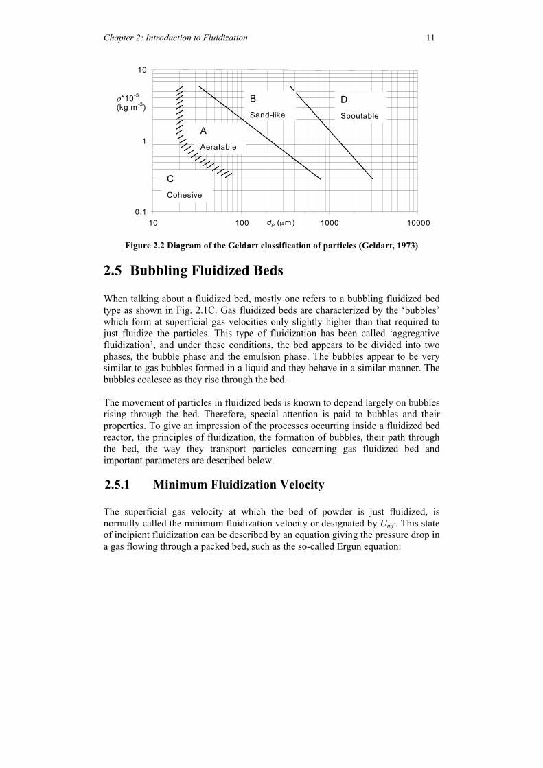
2.4 Geldart’s Classic Classification of Powders Not every particle can be fluidized. The behavior of solid particles in fluidized beds depends mostly on their size and density. A careful observation by Geldart (1973, 1978) is shown in Figure 2.2 in which the characteristics of the four different powder types were categorized as follows:
Chapter 2: Introduction to Fluidization 10
• Group A is designated as ‘aeratable’ particles. These materials have small mean particle size (dp < 30 µm) and/or low particle density (<~1.4 g/cm3). Fluid cracking catalysts typically are in this category. These solids fluidize easily, with smooth fluidization at low gas velocities without the formation of bubbles. At higher gas velocity, a point is eventually reached when bubbles start to form and the minimum bubbling velocity, Umb is always greater than Umf.
• Group B is called ‘sandlike’ particles and some call it bubbly particles. Most particles of this group have size 150 µm to 500 µm and density from 1.4 to 4 g/cm3. For these particles, once the minimum fluidization velocity is exceeded, the excess gas appears in the form of bubbles. Bubbles in a bed of group B particles can grow to a large size. Typically used group B materials are glass beads (ballotini) and coarse sand.
• Group C materials are ‘cohesive’, or very fine powders. Their sizes are usually less than 30 µm, and they are extremely difficult to fluidize because interparticle forces are relatively large, compared to those resulting from the action of gas. In small diameter beds, group C particles easily give rise to channeling. Examples of group C materials are talc, flour and starch.
• Group D is called ‘spoutable’ and the materials are either very large or very dense. They are difficult to fluidize in deep beds. Unlike group B particles, as velocity increases, a jet can be formed in the bed and material may then be blown out with the jet in a spouting motion. If the gas distribution is uneven, spouting behavior and severe channeling can be expected. Roasting coffee beans, lead shot and some roasting metal ores are examples of group D materials.
Geldart’s classification is clear and easy to use as displayed in Figure 2.2 for fluidization at ambient conditions and for U less than about 10·Umf. For any solid of a known density ρs and mean particle size dp this graph shows the type of fluidization to be expected. It also helps predicting other properties such as bubble size, bubble velocity, the existence of slugs etc.
Chapter 2: Introduction to Fluidization 11
0.1
1
10
10 100 1000 10000
C Cohesive
A Aeratable
B Sand-like
D Spoutable
ρ*10-3 (kg m-3)
dp (µm)
Figure 2.2 Diagram of the Geldart classification of particles (Geldart, 1973)
2.5 Bubbling Fluidized Beds When talking about a fluidized bed, mostly one refers to a bubbling fluidized bed type as shown in Fig. 2.1C. Gas fluidized beds are characterized by the ‘bubbles’ which form at superficial gas velocities only slightly higher than that required to just fluidize the particles. This type of fluidization has been called ‘aggregative fluidization’, and under these conditions, the bed appears to be divided into two phases, the bubble phase and the emulsion phase. The bubbles appear to be very similar to gas bubbles formed in a liquid and they behave in a similar manner. The bubbles coalesce as they rise through the bed. The movement of particles in fluidized beds is known to depend largely on bubbles rising through the bed. Therefore, special attention is paid to bubbles and their properties. To give an impression of the processes occurring inside a fluidized bed reactor, the principles of fluidization, the formation of bubbles, their path through the bed, the way they transport particles concerning gas fluidized bed and important parameters are described below.
2.5.1 Minimum Fluidization Velocity The superficial gas velocity at which the bed of powder is just fluidized, is normally called the minimum fluidization velocity or designated by Umf . This state of incipient fluidization can be described by an equation giving the pressure drop in a gas flowing through a packed bed, such as the so-called Ergun equation:
Chapter 2: Introduction to Fluidization 12
2 2
3 2 3
(1 ) (1 )150 1.75
( )mf mf mf g mf
s pmf s p mf
U UPL dd
ε µ ε ρφε φ ε
− −∆= + , (2.1)
in which ∆P is equal to the bed weight per unit cross-sectional area, and the particle sphericity, φs, is defined as the surface area of a volume equivalent sphere divided by the particle’s surface area. When applying the Ergun equation, one has to know the minimum fluidization voidage, εmf, although it is frequently an unknown. Wen and Yu (1966) developed an expression for the minimum fluidization velocity for a range of particle types and sizes by assuming the following approximations to hold based on experimental data:
2 3 3
1 111and 14mf
mf mf
εφ ε φε−
.
They combined these with the Ergun equation and obtained the relation:
( )32
2Re 33.7 0.0408 33.7p g s gp mf gmf
d gd U ρ ρ ρρµ µ
⋅ ⋅ − ⋅⋅ ⋅= = + − . (2.2)
Leva (1959) obtained empirically another widely used expression: 1.82 0.883 0.947.90 10 ( )pmf s f fU d ρ ρ µ −−= × − (2.3) This equation is valid for Re 10mf ≤ , whereas for higher values of a correction factor must be applied.
Remf
2.5.2 Bubble Size The mean size of the bubble population in fluidized beds increases with height above the distributor plate due to coalescence of bubbles. Researchers have attempted to predict the size of bubbles, not only the variation in mean size, but also the distributions of the diameters and volumes.
Chapter 2: Introduction to Fluidization 13
As far as the mean size is concerned, Geldart (1972) used the expression of Kato and Wen (1969) for the initial bubble size at the gas distributor. He asserted that a porous plate distributor behaves as a distributor plate with 1 hole per 10 cm2, and added his own empirical expression for the bubble growth with bed height due to coalescence:
0.42
0.940.2
0
( )1.43 2.05( )4mf bed
B mU U D
fD U U hNgπ −
= + −
(2.4)
where DB is the bubble diameter, Dbed is the diameter of the bed and N0 is the number of holes in the distributor plate. A number of other relationships have been proposed since then, some of which will be given and used in later chapters.
2.5.3 Bubble Wake When a bubble rises, it carries some amount of solids inside as seen in Fig. 2.3. This is called ‘wake’. The formation of a wake follows directly when the bubble forms. Hence, the bubble picks up most of its solids at the bottom of the bed as it leaves the distributor plate. An idealized bubble has an upper surface that is approximately spherical, with a radius of curvature r, and a wake at the bottom, with wake angle as shown in Figure 2.3. wθ
θwBubble volume
Wake volume
Bubble diameter
Radius of Curvature
Figure 2.3 A ideally spherical bubble (Geldart, 1962)
Chapter 2: Introduction to Fluidization 14
The bubble size is often expressed in terms of the volume equivalent diameter, Deq,
and can be calculated as
136 b
eqVDπ
=
, where Vb is a bubble volume.
Several researchers, for example Rowe and Widmer (1972) and Rowe and Yacono (1976) investigated the relationship of wake volume of a bubble as a function of its parameters, such as a bubble diameter, wake angle etc. by using X-ray techniques. The wake angle was also estimated by Naimer et al. (1982) who gave an empirical relation for the variation of the wake angle with the bubble diameter. Hoffmann (1983) proposed an improved equation for wake angle calculation: ( )160 160exp 60w BDθ = − − (2.4) where DB is the bubble diameter and θw is expressed in degrees. In some symposium publications (Hoffmann, 1991), a constant value of 55 is used instead of 60 in Equation 2.4, although the quality of the fit to the experimental data is essentially the same for the two constants. Equation 2.4 will be applied throughout this thesis. The other important parameter is the ratio of the volumes of the wake and the sphere and this is called the wake fraction fw:
334
ww
Vfrπ
= (2.5)
The wake volume, Vw can be calculated as a function of θw, DB and r. Vw is taken as the volume of that part of the circumscribing sphere not occupied by the bubble void for an approximation. Generally, moving from group A through group B to group D, the wake fraction decreases and therefore the volume of particulate phase transported per unit bubble volume decreases (Geldart, 1986). The wake of the bubble in beds of spherical material is roughly 30% of the bubble volume (Yates, 1983).
2.5.4 Bubble Rise Velocity The rise velocity of a large spherical cap bubble in a liquid is dependent on the radius of curvature at the nose of the bubble as described by Davies and Taylor (1950):
Chapter 2: Introduction to Fluidization 15
0.667bU g r= ⋅ . (2.6) A semi-empirical relation in terms of the volume-equivalent diameter is: 0.711bU g D= ⋅ eq . (2.7)
This expression is widely used for calculations of the velocity of rise of single bubbles in fluidized beds.
2.5.5 Bubble Flow Rate and the Two-Phase Theory According to the two-phase theory of fluidization proposed by Toomey and Johnstone (1952) and developed by Davidson and Harrison (1963), all gas in excess of that needed for minimum fluidization passes through the bed as bubbles. The particulate phase remains at minimum fluidizing conditions, which means that the voidage, not counting the bubbles, remains practically εmf. The visible flow rate in a fluidized bed Qb, defined as the rate at which bubble volume crosses any section A in the bed, is then approximately equal to the excess gas flow above that required for minimum fluidization (Davidson and Harrison, 1963):
bmf
Q U UA
= − (2.8)
2.5.6 The Davidson Model The movement of both gas and solid caused by the rise of bubbles can be described by the Davidson model (Davidson, 1961), assuming that the bubble is solid free and spherical, that particles behave like an incompressible fluid of bulk density ρs(1-εmf) and that the gas in the emulsion phase flows as an incompressible viscous fluid that obeys Darcy’s law. Davidson (1961) described the gas flow in terms of a stream function and found that the bubble velocity affects the geometry of the stream function. If the bubble moves slower than the gas in the emulsion phase, this gas uses the bubble as a shortcut, entering the bubble at the bottom and leaving it at the top. Some gas circulates with the bubble, moving upward with it. This circulation increases with the bubble rise velocity. If the bubble moves faster than the gas in the emulsion phase, all gas entering the bubble circulates and a “cloud” of recirculating gas is formed around the bubble, while the rest of the gas in the bed moves past it without
Chapter 2: Introduction to Fluidization 16
mixing. The gas in the bubble and the cloud is then essentially isolated from the rest of the gas in the bed except for dispersion mass transfer. Other extensions to the Davidson model can be made; for example, some workers claim that some particles fall through the bubble due to a thin, unstable layer of larger voidage around the upper boundary of the bubble, but this may be a feature of two-dimensional beds only. Another property of bubbles in dense beds is their break-up when they become too large. If the rise velocity of the bubble exceeds the terminal velocity of the particles (their free-fall velocity), the bubble becomes unstable and will break up into smaller bubbles. There are other models for the bubble movement in fluidized beds, which are more realistic than Davidson’s model for example, by Jackson (1963) and Murray (1965). However, the simple treatment of Davidson’s model is still essentially applied in many circumstances.
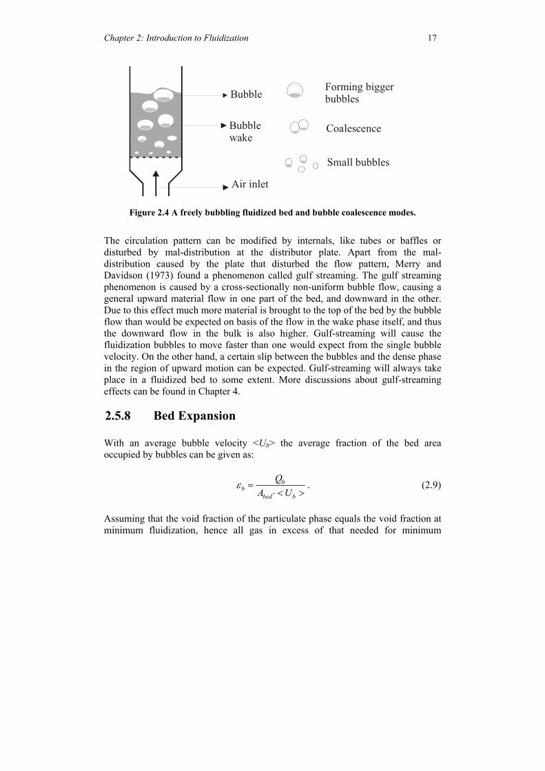
2.5.7 Flow Pattern of Fluidization Bubbles As bubbles rise through the bed, they coalesce to form bigger bubbles and when they become too large, they split (see Figure 2.4). The average bubble size equilibrates at about the maximum stable size. The location in the bed where the equilibrium size is attained depends on the kind of particles. For group A particles, the maximum stable diameter is relatively small, therefore the average bubble size stabilizes close to the distributor plate and remains constant through the rest of the bed. The maximum stable diameter for group B particles is larger and the equilibrium is reached typically only in the upper levels of the bed. The bubbles in group D particle beds behave differently; they do not rise as individual bubbles, but as horizontally associated swarms. Bubbles can coalesce in two ways, by incorporating a bubble in front or by moving side-wards into the track of another bubble and then incorporating it. At the wall of the bed, bubbles can only move inwards, while other bubbles can move in any horizontal direction. The result is an active zone away from the wall, which intensifies and moves closer to the axis with increasing distance from the distributor plate. Solid particles are dragged up by the bubbles and, by continuity, will move downwards in regions with lower bubble densities. As a consequence of fewer bubbles being close to the wall, there is a predominantly downward flow of particles near the wall, which, once established, maintains the tendency for bubbles to move inwards. The overall circulation is upwards near the axis and downwards near the wall in higher regions; the converse seems to be the case in the lower regions.
Chapter 2: Introduction to Fluidization 17
Bubble
Air inlet
Small bubbles
Coalescence
Forming bigger bubbles
Bubble wake
Figure 2.4 A freely bubbling fluidized bed and bubble coalescence modes.
The circulation pattern can be modified by internals, like tubes or baffles or disturbed by mal-distribution at the distributor plate. Apart from the mal-distribution caused by the plate that disturbed the flow pattern, Merry and Davidson (1973) found a phenomenon called gulf streaming. The gulf streaming phenomenon is caused by a cross-sectionally non-uniform bubble flow, causing a general upward material flow in one part of the bed, and downward in the other. Due to this effect much more material is brought to the top of the bed by the bubble flow than would be expected on basis of the flow in the wake phase itself, and thus the downward flow in the bulk is also higher. Gulf-streaming will cause the fluidization bubbles to move faster than one would expect from the single bubble velocity. On the other hand, a certain slip between the bubbles and the dense phase in the region of upward motion can be expected. Gulf-streaming will always take place in a fluidized bed to some extent. More discussions about gulf-streaming effects can be found in Chapter 4.
2.5.8 Bed Expansion With an average bubble velocity <Ub> the average fraction of the bed area occupied by bubbles can be given as:
bb
bed b
QA U
ε =⋅ < >
. (2.9)
Assuming that the void fraction of the particulate phase equals the void fraction at minimum fluidization, hence all gas in excess of that needed for minimum
Chapter 2: Introduction to Fluidization 18
fluidization passes through the bed as bubbles, the height h of the bed can be derived:
0
hb
mfbed b
Qh h dzA U
− =⋅ < >∫ . (2.10)
If the assumption can be made that the bubble velocity is constant throughout the bed, the bed height can be estimated from:
mf mf
mf b
h h U Uh U− −
= . (2.11)
The expansion of the bed then equals the fraction of the bed consisting of bubbles:
mfb
h hh
ε−
= . (2.12)
In practice, the bubble fraction is a bit lower than this theoretical value.
2.6 Particle Transportation Several mechanisms have been proposed to describe the movement of particles through a fluidized bed. Mechanisms governing the vertical particle transport processes in batch freely bubbling fluidized beds were first proposed by Rowe and Partridge (1962):
• Transport upwards in the wakes of fluidization bubbles and deposition on the bed surface
• Transport down to compensate for this (the combination of these two they called 'circulation') and
• Dispersion due to disturbance of the bed material by fluidization bubbles. In addition, the wake and drift exchange solids with the emulsion phase from experimental findings of Gibilaro and Rowe (1974), Chiba and Kobayashi (1977), Chiba et al. (1979) and Nienow and Chiba (1985). Mixing of solids occurs in both axial and radial directions. However, vertical solid mixing is generally many times faster than that due to lateral motion (Kunii and Levenspiel, 1991). More details of each mechanism are described below.
Chapter 2: Introduction to Fluidization 19
2.6.1 Solid Circulation Solid circulation is mainly determined by the gas velocity. At low gas velocities solids circulation is negligible. In more vigorously bubbling beds, circulation becomes appreciable and the absolute upward gas velocity through the emulsion phase does not equal the minimum fluidizing velocity anymore. Here, the velocity of the downward flowing solids has to be taken into account. Not only gas velocity, but also particle properties like shape, size, density, stickiness, and size distribution influence the mechanisms of axial and radial transport of particles within the bed. As mentioned previously, solids move in the vertical direction largely by being carried up by bubbles and carried down to the distributor by the bubble-free flow of particulate phase material. The upward movement is rapid (with the velocity of the bubbles) and the downward movement relatively slow.
2.6.2 Dispersion Dispersion is one of the mechanisms of solids mixing in a fluidized bed. It occurs due to the disturbance of the bed material caused by the motion of the bubbles. Although it is thus a discrete process, linked to the motion of each individual bubble, it can be described as a continuous dispersion process and modeled using the diffusion equation:
2
2ct
cx
∂ ∂=
∂ ∂D (2.13)
This equation is called Fick’s second law of diffusion or the diffusion equation, where is a dispersion coefficient and c the concentration of the diffusing species is a function of both x and t.
D
D In this thesis, the method for calculating the dispersion coefficient is by calculating the number and size of fluidization bubbles going through a given cross-section of the bed during a given time interval of t seconds and using empirical literature data for the particle drift caused by a single bubble. From equation 2.13, the solution to the one-dimensional diffusion of particles, the concentration of which initially forms a Dirac delta function in x = 0 is:
Chapter 2: Introduction to Fluidization 20
1( , )2
c x t etπ
−= D , where c(x,t) is the normalized particle concentration.
c(x,t)dx can, in the case of particles dispersing from a plane, be seen as the fraction
of the particles with position 1 12 2
x dx x x dx+ < < − at time t.
2
4x
tD
When comparing this with the density of the normal distribution,
1( )2
c u e σ
σ π=
−D
c u∞
−∞∫
, )x dx
D
, we see that the two are the same with σ2 = 2 t. 2
22u
Since the mean is zero, the variance σ2 is the expected value of u2: , so
that: or in other words: 2 t is the expected value of x
2( )u du
22 (t c x t∞
−∞
= ∫D D 2, which
is also the mean square particle displacement at time t. In what follows, we will use the mean square particle displacement per second, D = 2 , as a measure of dispersion. This is in line with what is common in the mathematical literature, but not in the engineering literature. After that we calculate the particle displacement caused by one bubble from the empirical profiles given by Chiba et al. (1976) and then calculate the cross-sectional mean of the square displacement. Taking t as the reciprocal of the bubble frequency at the given level in the bed, the dispersion coefficient used in our stochastic model is thus calculated. Only axial dispersion is taken into account. Horizontal and vertical diffusion differ, the axial, or vertical, dispersion coefficient being appreciably higher than the radial dispersion coefficient. An alternative to the above outlined concepts and method for estimating D is based on the notion of particle flow in and out of the bubble wake. This concept and the resulting expressions for the radial and axial dispersion coefficients are described below.
Chapter 2: Introduction to Fluidization 21
2.6.3 An Alternative Concept: Solid Exchange Between the Wake and the Emulsion
According to the extensions of bubbling bed model (the Davidson model), particles travel upwards in a wake and downwards in the particulate phase. As described before, the idealized bubble carries up solids in a closed wake, with the solids circulating within it. However, models have been proposed that include interchange of solids between the wake and the particulate phase. It was suggested that in beds of fast rising bubbles, the downward moving particles in the cloud around the bubble are swept into the wake and are fluidized there by the circulating gas. In the wake they are uniformly mixed by circulation and, by continuity, particles leave the wake at the same rate. The coefficient of interchange of solids between the cloud-wake region and the particulate phase, based on bubble size, was derived by Yoshida and Kunii (1968):
( )
( )3 1
1mf mf
wb mf b
UK
D
ε
ε ε
⋅ −= ⋅
− ⋅. (2.14)
The circulation in the wake gives rise to radial mixing of solids. Solids farther from the bubble move aside somewhat as the bubble passes by and then return close to their original position; for them, radial mixing can be neglected. Using terms of the bubbling bed model and the solids interchange model from Kunii and Levenspiel, 1991 , the following axial and radial dispersion coefficient, Dsa and Dsr respectively, can be found:
2 2( (1 ))
(1 )(1 )w b mf b
sab w b mf
f UD
Kε ε
ε ε ε−
=− −
(2.15)
substituting Kw from equation 2.14 and simplifying, thus;
2
2
3w mf b
sa Bmf
fbD D U
Uε ε
= . (2.16)
The above model for the solid exchange, Equation (2.14), was refined in the light of experimental results by Chiba et al. (1976, 1979). They have developed the following equations:
Chapter 2: Introduction to Fluidization 22
4 mfw
mf B
UK
Dπ ε= for a 2-dimensional bubble (2.17)
32
mfw
mf B
UK
Dε= for a 3-dimensional bubble (2.18)
Solid mixing in a freely bubbling fluidized bed is caused not only by the vertical movement of bubbles and bursting of bubbles at the bed surface, but also by the lateral motion of bubbles as a result of the interaction and coalescence of neighboring bubbles. However, the lateral mixing of solids which is augmented by the lateral motion of bubbles is relatively small compared to the vertical motion of solids. Our stochastic model is one-dimensional at the present time, and we therefore do not consider the issue of radial mixing. This a different concept in that the dispersion coefficient accounts for dispersion both due to the bubble's stirring action and due to take-up of particles in the bubble wake. The approach used in this thesis is to calculate a dispersion coefficient only on basis of the stirring action, and take the transport in bubble wakes into account in jumps to the bed surface. In the latter approach the material exchange between the bubble wake and bulk is assumed to be zero, although the model can easily be modified to take exchange with the bulk into account.
2.7 Particle Mixing and Segregation Until now we have implicitly assumed that the bed particles are uniform. However, if the bed particles differ in physical properties, notably size and density, then segregation can take place. Segregation of a binary mixture of particles occurs when there is a substantial difference between their drag per unit weight. A high drag per unit weight makes the particles move upwards, whereas particles with a low drag per unit weight will tend to sink to the bottom. These two types of particles are called flotsam and jetsam, respectively. A quantitative measure for segregation is given by Tanimoto et al. (1981) in terms of the segregation distance Y, made dimensionless with the radius of the fluidization bubble. It characterizes the distance over which the jetsam particles sink as a single bubble passes by. The segregation distance was modified by Hoffmann and Romp (1991) to ensure that Y becomes zero when the bed particles are uniform:
Chapter 2: Introduction to Fluidization 23
13
0.8 0.8j j
f f
dY
dρρ
= ⋅ ⋅ −
(2.19)
This shows that the particle density difference is more dominant in segregation than the size difference. The superficial segregation velocity depends on the segregation distance as follows:
( )34segr mfv Y U U= ⋅ ⋅ − (2.20)
The competitive mechanisms of segregation and mixing occur simultaneously producing equilibrium through the bed. Radial distribution is essentially uniform and axial distribution varies with height (Gibilaro and Rowe, 1973). As the gas velocity increases, the segregation pattern changes from a pure jetsam layer at the bottom through a gradient in jetsam concentration to a uniform mixture. As the composition of the mixture of particles varies with bed height, so does the minimum fluidization velocity. In some cases, segregation leads to defluidization in the bottom of the bed. The segregating fluidized bed containing two types of particles has been modeled by Gibilaro and Rowe (1974), who recognized four physical mechanisms: overall particle circulation, interchange between bulk and wake phases, axial spreading and a relative segregating flow rate. The first three are modes of mixing and only the last mechanism distinguishes jetsam and flotsam. Segregation, like mixing, depends almost solely on bubbles. Naimer et al. (1982) suggested a segregation mechanism where jetsam can overtake flotsam by falling rapidly through bubbles. Jetsam particles also descend faster through the temporarily disturbed region with lower density below each bubble. This mechanism is illustrated in Fig. 2.5, where a jetsam layer is disturbed by a bubble moving through it.
Chapter 2: Introduction to Fluidization 24
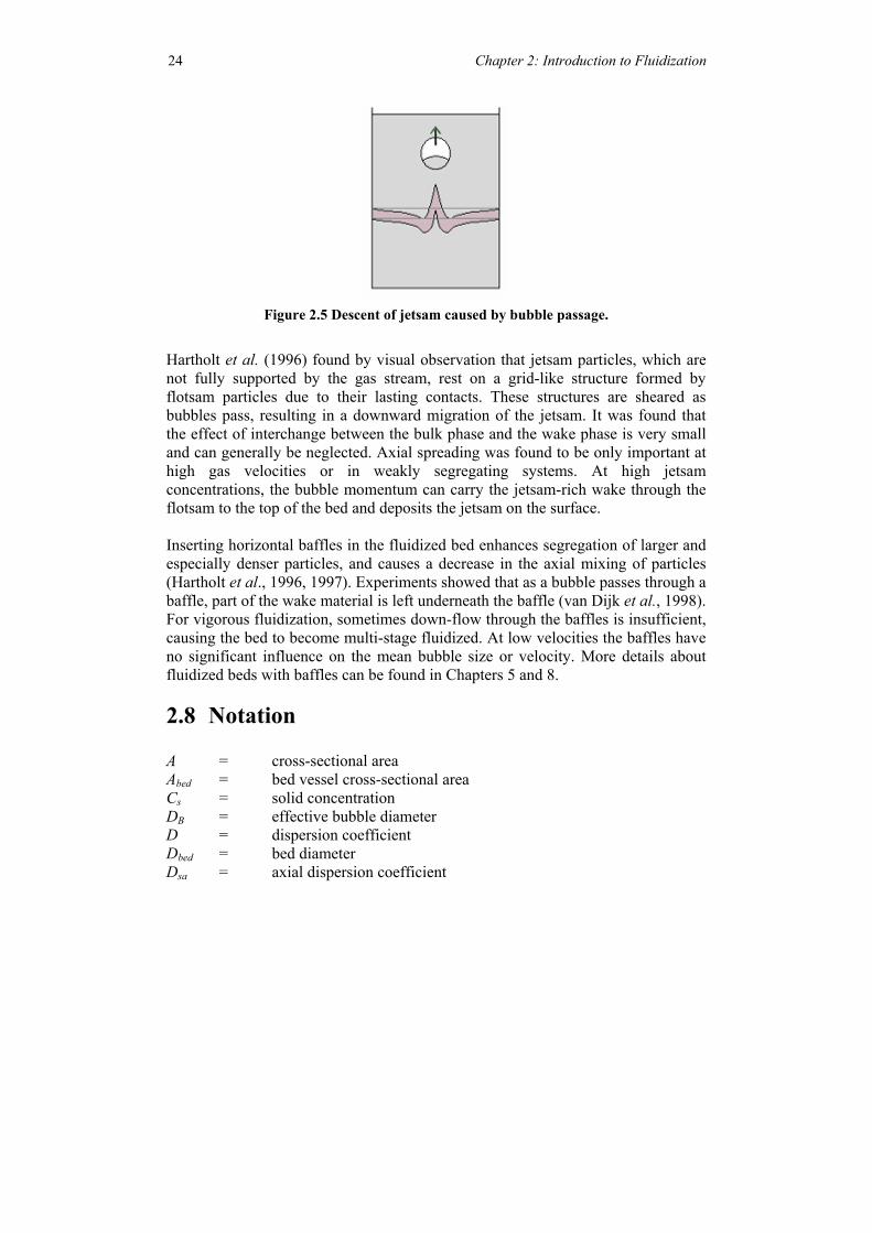
Figure 2.5 Descent of jetsam caused by bubble passage.
Hartholt et al. (1996) found by visual observation that jetsam particles, which are not fully supported by the gas stream, rest on a grid-like structure formed by flotsam particles due to their lasting contacts. These structures are sheared as bubbles pass, resulting in a downward migration of the jetsam. It was found that the effect of interchange between the bulk phase and the wake phase is very small and can generally be neglected. Axial spreading was found to be only important at high gas velocities or in weakly segregating systems. At high jetsam concentrations, the bubble momentum can carry the jetsam-rich wake through the flotsam to the top of the bed and deposits the jetsam on the surface. Inserting horizontal baffles in the fluidized bed enhances segregation of larger and especially denser particles, and causes a decrease in the axial mixing of particles (Hartholt et al., 1996, 1997). Experiments showed that as a bubble passes through a baffle, part of the wake material is left underneath the baffle (van Dijk et al., 1998). For vigorous fluidization, sometimes down-flow through the baffles is insufficient, causing the bed to become multi-stage fluidized. At low velocities the baffles have no significant influence on the mean bubble size or velocity. More details about fluidized beds with baffles can be found in Chapters 5 and 8.
2.8 Notation A = cross-sectional area Abed = bed vessel cross-sectional area Cs = solid concentration DB = effective bubble diameter D = dispersion coefficient Dbed = bed diameter Dsa = axial dispersion coefficient
Chapter 2: Introduction to Fluidization 25
Dsr = radial dispersion coefficient Deq = the diameter of a volume equivalent sphere dp = particle diameter
pd = mean particle diameter fd = drift fraction fw = wake fraction h = height in the bed hmf = height of the bed at Umf Kw = solid exchange coefficient between wake and emulsion phase L = bed height N0 = number of holes of a distributor plate ∆P = pressure drop Qb = visible gas flow rate in a fluidized bed r = radius of curvature of the bubble front Remf = Reynolds number of particle at minimum fluidization condition Reb = Reynolds number of bubbles t = time U = velocity <U> = average bubble velocity Ub = bubble velocity U0 = superficial fluid velocity Umf = superficial fluid velocity at minimum fluidizing conditions vsegr = superficial segregation velocity Vb = a bubble volume Vw = a wake volume Y = dimensionless segregation distance Greek symbols: µ = viscosity of fluid ε = void fraction εb = fraction of bed occupied by bubbles εmf = void fraction at minimum fluidization condition θw = wake angle ρ = density ρf = flotsam density ρj = jetsam density ρs = solid density
Chapter 2: Introduction to Fluidization 26
2.9 References Davies R.M. and Taylor G.I., “The mechanics of large bubbles rising through extended liquids and through liquids in tubes”, Proc. Roy. Soc., A200 (1950), 375. Davidson J.F. and Harrison D., Fluidized Particles, Cambridge University Press, New York, 1963. Geldart, D., Gas Fluidization Technology, John Wiley&Sons, New York, 1986. Geldart D., “Homogenous Fluidization in Fine Powder Using Various Gases and Pressures”, Powder Technol. 19 (1978), 133-136. Geldart D., “Types of Gas Fluidization”, Powder Technol. 7 (1973), 285-292. Gibilaro L.G. and Rowe P.N., “A Model for a Segregation Gas Fluidized Bed”, Chem. Eng. Sci. 29 (1974), 1403-1412. Hartholt G.P., Hoffmann A.C. and Janssen L.P.B.M., “Visual Observations of Individual Particle Behavior in Gas and Liquid Fluidized Beds”, Powder Technol., 88 (1996), 341. Helland E., Dalloz-Dubrujeaud B., Occelli R., Faure R. and Tadrist L., “An Investigation of Gas-Particle Flow Behavior in a Two Dimensional dens Fluidized bed”, Proceedings of the 3rd European Conference on Fluidization, Toulouse, 2000. Hoffmann, A.C., Ph.D. thesis, University College London, Department of Chemical and Biochemical Engineering, 1983. Hoffmann, A.C. and Romp, E.J. “Segregation in a Fluidised Powder of a Continuous Size Distribution”, Powder Technol. 66 (1991), 119-126. Hoffmann, A.C., Janssen, L.P.B.M and Prins, J. “Particle Segregation in Fluidised Binary Mixtures”, Chem. Eng. Sci. 48 (1993), 1583-1592. Kato, K. and C.Y. Wen, “Bubble assemblage model for fluidized bed catalytic reactors”, Chem. Eng. Sci. 24 (1969), 1351-69. Kunii D. and Levenspiel O., Fluidization Engineering, second edition, Butterworth-Heinemann, Stoneham, 1991.
Chapter 2: Introduction to Fluidization
27
Larachi F. and Chaouki J., “Non Invasive 3-D Particle Tracking in Heterogeneous Flows: Principle & Applications”, Proceedings of the 3rd European Conference on Fluidization, Toulouse, 2000. Leva M., Fluidization, McGraw-Hill, New York, 1959. Merry, J.M.D. and Davidson, J.F., “Gulf-stream circulation in shallow fluidized-beds”, Trans. Instn. Chem. Engrs. 81 (1973), 361-368. Naimer N.S., Chiba T. and Nienow A.W., “Parameter Estimation for a Solids Mixing/Segregation Model for Gas Fluidized Beds”, Chem. Eng. Sci. 37 (1982), 1047-1057. Nicklin, D.J., “Two phase bubble flow”, Chem. Eng. Sci. 17 (1962), 693-702. Nienow, A.W., Naimer N.S. and Chiba T., “Studies of segregation/mixing in fluidized beds of different size particles”, Chem.Eng.Sci. 62 (1987), 53-66. Newton D., Fiorentino M. and Smith G.B., “The Application of X-ray Imaging to the Developments of Fluidized Bed Processes”, Proceedings of the 3rd European Conference on Fluidization, Toulouse, 2000. Nowak W., Pisarek J. and Mirek P., “Application of Laser Sheet Technique for Analysis of 3D Particle Velocity Fields in Fluidized Beds”, Proceedings of the 3rd European Conference on Fluidization, Toulouse, May 2000. Rowe P.N., Nienow A.W. and Agbim A.J., “The Mechanisms by which Particles Segregate in Gas Fluidized Beds-Binary Systems of near Spherical Particles”, Transactions Institution Chemical Engineers 50 (1972), 310-323. Rowe P.N., Partridge B.A., Cheney A.G and Henwood G.A., “The Mechanics of Solids Mixing in Fluidized Beds”, Transactions Institution Chemical Engineers 43 (1965), 271-286. Rowe P.N. and Yacono C.X.R., “Bubbling behavior of fine powders when fluidized”, Chem. Engng. Sci., 31 (1976), 1179-119. Rowe P.N. and Widmer A.J., “Variation in shape with size of bubbles in fluidized-beds”, Chem. Engng. Sci., 28 (1972), 980-981.
Chapter 2: Introduction to Fluidization
28
Seville J.P.K., Ding Y.L. and Stein M., “Particle Motion in Bubbling Fluidized Beds”, Proceedings of the 3rd European Conference on Fluidization, Toulouse, 2000. Sorenson J.A. and Phelps M.E., Physics of Nuclear Medicine, second edition, W.B. Saunders Company, Philadelphia, 1987. Tanimoto H., Chiba S., Chiba T. and Kobayashi H., “Jetsam Descent Induced by a Single Bubble Passage in Three-dimensional Gas-Fluidized Beds”, Journal of chemical Engineering of Japan, 14 (1981), 273-276. Toomey, R.D. and Johnstone, H.F., “Gaseous fluidization of solid particles”, Chem.Eng.Progr., 48 (1952), 200. Van Deemster, J. J., Proc. Inst. Symp. on Fluidization: Netherlands Univ. Press, (1967), 334. Webb S., Physics of Medical Imaging, IOP Publishing Ltd., Bristol, 1988. Wen C.Y. and Yu Y.H., “A Generalized Method for Predicting the Minimum Fluidization Velocity”, American Institute of Chemical Engineering Journal, 12 (1966), 610-612. Wirsum M., Fett F., Iwanowa N. and Lukjanow G., “Particle Mixing in Bubbling Fluidized Beds of Binary Particle Systems”, Proceedings of the 3rd European Conference on Fluidization, Toulouse, 2000. Yates J.G., Fundamental of fluidized-bed chemical processes, Butterworths, London, 1983. Yoshida, K., and Kunii, D., J.Chem.Eng. Japan, 1 (1968), 11. Zarabi T. and Kantzas A., “Predictions of Bubble and Solids Movement in Laboratory Polyethylene Fluid Beds as Visualized by X-ray Computer Assisted Tomography (CAT) Scanning”, Canadian Journal of Chemical Engineering, 76 (1998), 853-865.


![PARTICLE SIZE, PARTICLE SIZE DISTRIBUTION & COMPACTION AND COMPRESSION [PREFORMULATION STUDY] (1-32)](https://static.documents.pub/doc/80x56/56649e855503460f94b87eac/particle-size-particle-size-distribution-compaction-and-compression-preformulation.jpg)