University of Huddersfield Repository Achilleos, Paris Design optimisation of a diffuser for a turbocharger compressor stage Original Citation Achilleos, Paris (2014) Design optimisation of a diffuser for a turbocharger compressor stage. Masters thesis, University of Huddersfield. This version is available at http://eprints.hud.ac.uk/id/eprint/23751/ The University Repository is a digital collection of the research output of the University, available on Open Access. Copyright and Moral Rights for the items on this site are retained by the individual author and/or other copyright owners. Users may access full items free of charge; copies of full text items generally can be reproduced, displayed or performed and given to third parties in any format or medium for personal research or study, educational or not-for-profit purposes without prior permission or charge, provided: • The authors, title and full bibliographic details is credited in any copy; • A hyperlink and/or URL is included for the original metadata page; and • The content is not changed in any way. For more information, including our policy and submission procedure, please contact the Repository Team at: [email protected]. http://eprints.hud.ac.uk/
Transcript
University of Huddersfield Repository
Achilleos, Paris
Design optimisation of a diffuser for a turbocharger compressor stage
Original Citation
Achilleos, Paris (2014) Design optimisation of a diffuser for a turbocharger compressor stage. Masters thesis, University of Huddersfield.
This version is available at http://eprints.hud.ac.uk/id/eprint/23751/
The University Repository is a digital collection of the research output of theUniversity, available on Open Access. Copyright and Moral Rights for the itemson this site are retained by the individual author and/or other copyright owners.Users may access full items free of charge; copies of full text items generallycan be reproduced, displayed or performed and given to third parties in anyformat or medium for personal research or study, educational or notforprofitpurposes without prior permission or charge, provided:
• The authors, title and full bibliographic details is credited in any copy;• A hyperlink and/or URL is included for the original metadata page; and• The content is not changed in any way.
For more information, including our policy and submission procedure, pleasecontact the Repository Team at: [email protected].
http://eprints.hud.ac.uk/
Design Optimisation of a Diffuser for a Turbocharger Compressor By Paris Achilleos, School of Computing and Engineering, University of Huddersfield, UK (2014)
DESIGN OPTIMISATION OF A DIFFUSER
FOR A TURBOCHARGER COMPRESSOR
STAGE
Paris Achilleos
M(Res)
2014
University of Huddersfield
School of Computing and Engineering
Design Optimisation of a Diffuser for a Turbocharger Compressor By Paris Achilleos, School of Computing and Engineering, University of Huddersfield, UK (2014)
ii
ABSTRACT
The need for energy saving within the automotive industry becomes greater each year due to the
continued pollution of the environment from the fossil fuels, and the amount of NOx emissions
released in the environment from ground vehicles. Turbochargers are among those components that
provide solutions to the energy saving for automotive vehicles, especially for the commercial
division of ground vehicles. Significant developments in this field have been witnessed in the last
decade using both the numerical and experimental investigations. However, the regulations of E.U
regarding the energy saving has motivated the automotive industry to investigate new methods for
improving the performance of turbochargers, decreasing the fuel consumption and lowering the
emissions release in the environment from ground vehicles. Hence, this numerical investigation is
primarily focused on the optimisation of the diffuser of a turbocharger compressor stage.
The primary goal of this study is to numerically model and investigate the compressor stage of a
turbocharger using advanced Computational Fluid Dynamics (CFD) based techniques. The model
has been investigated at lower operating speeds i.e. 60,000rpm and 80,000rpm. Multiple Reference
Frame (MRF) approach has been employed for simulating the steady flow of air through the
compressor stage of the turbocharger. In an effort to optimise the diffuser geometry, non-parallel
walls approach has been used. In this approach, the shroud side wall of the diffuser has been made
non-parallel to the hub side wall, in a number of configurations. These configurations have been
numerically analysed in order to evaluate the effects of pinching and diffusion, where pinching
corresponds to diverting the shroud wall of the diffuser by a certain angle and at a certain distance
from the inlet of the diffuser, while diffusion corresponds to the increase in the diffuser’s width at
its outlet section, as compared to its inlet section. Both qualitative and quantitative flow analysis
has been carried out in detail in order to find optimum diffuser geometry. Furthermore, this thesis
provides an insight on the flow structure within a compressor stage of a turbocharger, and reveals
possible mechanisms that affect its performance characteristics.
Design Optimisation of a Diffuser for a Turbocharger Compressor By Paris Achilleos, School of Computing and Engineering, University of Huddersfield, UK (2014)
iii
DECLARATION
The author of this thesis (including any appendices and/or schedules to this thesis) owns any
copyright in it (the “Copyright”) and he has given The University of Huddersfield the right
to use such Copyright for any administrative, promotional, educational and/or teaching
purposes.
Copies of this thesis, either in full or in extracts, may be made only in accordance with the
regulations of the University Library. Details of these regulations may be obtained from the
Librarian. This page must form part of any such copies made.
The ownership of any patents, designs, trademarks and any and all other intellectual
property rights except for the Copyright (the “Intellectual Property Rights”) and any
reproductions of copyright works, for example graphs and tables (“Reproductions”), which
may be described in this thesis, may not be owned by the author and may be owned by third
parties. Such Intellectual Property Rights and Reproductions cannot and must not be made
available for use without the prior written permission of the owner(s) of the relevant
Intellectual Property Rights and/or Reproductions.
Design Optimisation of a Diffuser for a Turbocharger Compressor By Paris Achilleos, School of Computing and Engineering, University of Huddersfield, UK (2014)
iv
ACKNOWLEDGEMENTS
First and most importantly, I would like to acknowledge my family and my supervisor Prof. Rakesh
Mishra who provided support and encouragement throughout this study and made it possible. I
would also like to acknowledge my friend Dr. Taimoor Asim who provided valuable help and
support throughout this project. I cannot express my gratitude enough to Prof. Rakesh Mishra.
I would also like to thank Dr. Paul Eynon and Dr. Michael Dolton, my industrial supervision team
from Cummins Turbo Technologies (CTT), for their support and guidance.
Design Optimisation of a Diffuser for a Turbocharger Compressor By Paris Achilleos, School of Computing and Engineering, University of Huddersfield, UK (2014)
v
CONTENTS
Abstract ............................................................................................................................................... II
Declaration ......................................................................................................................................... III
Acknowledgements ............................................................................................................................ IV
Contents .............................................................................................................................................. V
List of Figures .................................................................................................................................... IX
List of Tables .................................................................................................................................. XIII
Design Optimisation of a Diffuser for a Turbocharger Compressor By Paris Achilleos, School of Computing and Engineering, University of Huddersfield, UK (2014)
vi
1.10 Research Aims ........................................................................................................................... 15
1.11 Organisation of Thesis ............................................................................................................... 15
Chapter 2 Literature Review .......................................................................................................... 17
Design Optimisation of a Diffuser for a Turbocharger Compressor By Paris Achilleos, School of Computing and Engineering, University of Huddersfield, UK (2014)
vii
Chapter 4 Performance evaluation of the Baseline Turbocharger Compressor Stage ............. 46
4.1 Flow Characteristics of the Baseline Centrifugal Compressor Stage .......................................... 47
5.3.6 Static Temperature ...................................................................................................... 111
Design Optimisation of a Diffuser for a Turbocharger Compressor By Paris Achilleos, School of Computing and Engineering, University of Huddersfield, UK (2014)
Design Optimisation of a Diffuser for a Turbocharger Compressor By Paris Achilleos, School of Computing and Engineering, University of Huddersfield, UK (2014)
Figure 4.1 Variations in Total-to-Total Pressure Ratio with respect to Mass Flow Rate from both the
Experimental and CFD results ........................................................................................................... 48
Design Optimisation of a Diffuser for a Turbocharger Compressor By Paris Achilleos, School of Computing and Engineering, University of Huddersfield, UK (2014)
x
Figure 4.2 Variations in Efficiency with respect to Mass Flow Rate from both the Experimental and
Design Optimisation of a Diffuser for a Turbocharger Compressor By Paris Achilleos, School of Computing and Engineering, University of Huddersfield, UK (2014)
xi
Figure 4.21 Variations in static temperature (in K) within the diffuser at 4th
Design Optimisation of a Diffuser for a Turbocharger Compressor By Paris Achilleos, School of Computing and Engineering, University of Huddersfield, UK (2014)
xii
Figure 5.14 Variations in Efficiency for various suddenly expanding diffuser configurations at
Figure 5.24 Variations in azimuthal velocity (in m/s) within the optimised diffuser at 4th
design
point and 60,000rpm ........................................................................................................................ 108
Figure 5.25 Absolute azimuthal velocity variations within the optimised diffuser at 4th
design point
and 60,000rpm corresponding to (a) 0° (b) 90° (c) 180° (d) 270° ................................................... 109
Figure 5.26 Variations in static temperature (in K) within the optimised diffuser at 4th
design point
and 60,000rpm ................................................................................................................................. 111
Figure 5.27 Absolute static temperature variations within the optimised diffuser at 4th
design point
and 60,000rpm corresponding to (a) 0° (b) 90° (c) 180° (d) 270° ................................................... 112
Figure 5.28 Static Pressure Recovery within the Optimised Diffuser ............................................. 114
Design Optimisation of a Diffuser for a Turbocharger Compressor By Paris Achilleos, School of Computing and Engineering, University of Huddersfield, UK (2014)
Table 4.1 Percentage differences in absolute static pressure at various measuring locations ........... 60
Table 4.2 Percentage differences in Mach number at various measuring locations .......................... 63
Table 4.3 Percentage differences in axial velocity at various measuring locations ........................... 67
Table 4.4 Percentage differences in radial velocity at various measuring locations ......................... 70
Table 4.5 Percentage differences in azimuthal velocity at various measuring locations ................... 73
Table 4.6 Percentage differences in static temperature at various measuring locations .................... 76
Table 5.1 Diffuser design configurations for various pinch locations ............................................... 81
Table 5.2 Diffuser design configurations for various divergent angles ............................................. 82
Table 5.3 Percentage increase in pressure ratio between baseline and N/Nmax=0.5 diffuser
geometries for b2/b1=1.05 at 60,000rpm ............................................................................................ 83
Table 5.4 Percentage increase in efficiency between baseline and N/Nmax=0.5 diffuser geometries
for b2/b1=1.05 at 60,000rpm .............................................................................................................. 84
Table 5.5 Percentage increase in pressure ratio between baseline and N/Nmax=0.5 diffuser
geometries for b2/b1=1.07 at 60,000rpm ............................................................................................ 85
Table 5.6 Percentage increase in efficiency between baseline and N/Nmax=0.5 diffuser geometries
for b2/b1=1.07 at 60,000rpm .............................................................................................................. 86
Table 5.7 Percentage increase in pressure ratio between baseline and N/Nmax=0.5 diffuser
geometries for b2/b1=1.13 at 60,000rpm ............................................................................................ 87
Table 5.8 Percentage increase in efficiency between baseline and N/Nmax=0.5 diffuser geometries
for b2/b1=1.13 at 60,000rpm .............................................................................................................. 88
Table 5.9 Percentage increase in pressure ratio between baseline and N/Nmax=0.5 diffuser
geometries for b2/b1=1.18 at 60,000rpm ............................................................................................ 89
Table 5.10 Percentage increase in efficiency between baseline and N/Nmax=0.5 diffuser geometries
for b2/b1=1.18 at 60,000rpm .............................................................................................................. 90
Table 5.11 Percentage increase in pressure ratio between baseline and N/Nmax=0.5 diffuser
geometries for b2/b1=1.33 at 60,000rpm ............................................................................................ 91
Design Optimisation of a Diffuser for a Turbocharger Compressor By Paris Achilleos, School of Computing and Engineering, University of Huddersfield, UK (2014)
xiv
Table 5.12 Percentage increase in efficiency between baseline and N/Nmax=0.5 diffuser geometries
for b2/b1=1.33 at 60,000rpm .............................................................................................................. 92
Table 5.13 Percentage increase in pressure ratio between baseline and suddenly expanding diffuser
geometries at 60,000rpm .................................................................................................................... 93
Table 5.14 Percentage increase in efficiency between baseline and suddenly expanding diffuser
geometries at 60,000rpm .................................................................................................................... 94
Table 5.15 Percentage differences in absolute static pressure at various measuring locations ......... 99
Table 5.16 Percentage differences in Mach number at various measuring locations ...................... 102
Table 5.17 Percentage differences in axial velocity at various measuring locations ....................... 105
Table 5.18 Percentage differences in radial velocity at various measuring locations ..................... 108
Table 5.19 Percentage differences in azimuthal velocity at various measuring locations ............... 111
Table 5.20 Percentage differences in static temperature at various measuring locations ................ 114
INTRODUCTION
Design Optimisation of a Diffuser for a Turbocharger Compressor By Paris Achilleos, School of Computing and Engineering, University of Huddersfield, UK (2014)
1
CHAPTER 1
INTRODUCTION
his chapter provides an overview of current automotive vaneless diffusers and
their associated components. In this review, the basic performance
parameters of an automotive turbocharger are discussed, focusing on the
centrifugal compressor stage and exploring the mechanisms that affect the
performance output of a turbocharger. Additionally, the importance of vaneless
diffusers for the design and development of radial turbo-machines are discussed.
Existing design configurations and optimisation procedures were also examined, in
order to explore some of the key geometric characteristics that are related to the
vaneless diffuser’s performance output. This chapter also highlights the importance of
the interaction of diffuser-volute, where a number of key questions are raised that
correspond to the recent needs of turbochargers for higher efficiencies and reduction
of package sizing. The reasons and purpose for carrying out this research, and the
main aims of this study are emphasised in this chapter.
T
INTRODUCTION
Design Optimisation of a Diffuser for a Turbocharger Compressor By Paris Achilleos, School of Computing and Engineering, University of Huddersfield, UK (2014)
2
1.1 Introduction to Turbochargers
Turbochargers are amongst the most complicated and sophisticated pieces of engineering that
require high precision and are commonly used to a great extent for a variety of internal
combustion engines. For the automotive applications, the turbocharger utilizes the waste energy
from the exhaust gas, which is driven into the turbine housing. A typical turbocharger is shown
in figure 1.1.
Figure 1.1 Turbocharger [1]
1.2 Background of Turbochargers
Late in the 19th
century, a French Professor August Rateau invented the centrifugal compressor.
By 1899, he had a single-stage prototype on his test stand, compressing 0.5m3/s of atmospheric
air to a discharge pressure of 1.5bar (absolute) at a rotational speed of 200,000rpm (Engeda,
1988). Prof. August Rateau (1905) built the first multistage unit with five stages on one shaft of
the centrifugal compressor. The history of automotive turbochargers began as early as year 1885;
Gottlieb Daimler and Rudolf Diesel (1896) investigated increase in the power output and
reduction in the fuel consumption of their engines by recompressing the combustion air. Alferd
Büchi, chief engineer for Sulez Brothers, Switzerland (1925), was the first to be successful with
exhaust gas turbo-charging. This new technology was adopted by the automotive industry and
now it has become a major research field for ground vehicles.
INTRODUCTION
Design Optimisation of a Diffuser for a Turbocharger Compressor By Paris Achilleos, School of Computing and Engineering, University of Huddersfield, UK (2014)
3
1.3 Working of a Turbocharger
When the combustion process takes place in the engine, the waste energy exits in a form of
exhaust gas. The flow enters the turbine housing from the turbine volute (as shown in figure 1.2).
The flow enters the wheel in a radial direction, which forces the turbine to rotate at high speeds.
This process produces torque that is delivered from the shaft to the compressor’s impeller.
Figure 1.2 Working of a Turbocharger [2]
As the compressor’s impeller rotates, low pressure is created upstream of the compressor section
by the work of the impeller. Due to this low upstream pressure, the compressor section of the
turbocharger drifts in ambient air. As the impeller of the compressor stage is rotating at high
rpms, it transfers part of its momentum to the incident air flow, and forces the air to rotate at high
velocities. The flow then leaves the impeller in radial direction, and the flow discharges in an
annular passage. This passage is known as the diffuser, which is used to increase the pressure of
the air flow by diffusing it. This is achieved because the outlet area of the diffuser is more than
its inlet area. Usually a scroll follows the diffuser, where an attempt to collect the flow is made,
and then the flow is directed in to the cylinders of the engine. As the turbocharger forces more
compressed air to enter the cylinders, for a specific amount of fuel, more power can be generated
from a smaller sized engine, with reduced emissions. This is the primary purpose of a
turbocharger i.e. to increase the engine power without increasing the emissions from the engine.
.
INTRODUCTION
Design Optimisation of a Diffuser for a Turbocharger Compressor By Paris Achilleos, School of Computing and Engineering, University of Huddersfield, UK (2014)
4
1.4 Components of a Turbocharger Compressor Stage
The main components of a typical turbocharger’s compressor stage are discussed below.
Self-Recirculation Casing Treatment 1.4.1
Self-Recirculation Casing Treatment (SRCT) is the most modern method that increases a
turbocharger’s operational range by interfering with the boundary layers at the entry of the
diffuser. This is possible due to the static pressure field variations under specific operating
conditions as suggested by Hathaway et al [3] and Sivagnanasudaram et al [4]. For a typical
design in automotive turbochargers, the SRCT usually consists of grooves, circumferential into
the inlet duct, with two bleeds (as shown in figure 1.3). The first bleed is before the inducer and
the second one is after the inducer. Close to surge operating condition (which is one of the
extremities of a turbocharger’s operation), the system recycles the low energy fluid from the
bleed close to the impeller, and sends it back to the inducer through the first bleed. On the other
hand, close to choke operating condition (which is the other extremity of a turbocharger’s
operation), more flow is injected to the impeller through the bleed that is located close to the
inducer. These two procedures can remove any kind of unsteadiness that can develop at the
Design Optimisation of a Diffuser for a Turbocharger Compressor By Paris Achilleos, School of Computing and Engineering, University of Huddersfield, UK (2014)
5
The Impeller 1.4.2
The impeller is one of the most important components of a turbocharger’s compressor stage. The
impeller is rotated by a shaft, connected to the wheel of the turbine stage of the turbocharger.
The impeller transfers its energy to the incoming fluid, hence increasing fluid’s energy. This is
achieved by momentum transfer mechanism. A typical impeller of a compressor is shown in
figure 1.4.
Figure 1.4 Impeller of a Turbocharger Compressor Stage [2]
The fluid flow through the impeller is three-dimensional, the s three main velocity components
being in axial direction (Cx), in radial direction (Cr), and in azimuthal or tangential direction (Cθ).
The incidents angle of the flow with the impeller is critical, affecting the performance of the
compressor stage, and can generate series of instabilities, as discussed by Pinarbasi [5] and
Japikse [6]. The shape of the blades drives the flow into a radial direction in order to discharge
the fluid from the edge of the impeller blades.
Diffuser 1.4.3
Diffuser is also a very important component of a turbocharger’s compressor stage. A diffuser
consists of two parallel circular plates, with a gap in between them, so that the flow of air, from
the impeller, can pass through them. The diffusers are either vaneless or vaned. As this study
presents investigations into vaneless diffusers only, figure 1.5 shows a typical vaneless diffuser
for the compressor stage of a turbocharger.
INTRODUCTION
Design Optimisation of a Diffuser for a Turbocharger Compressor By Paris Achilleos, School of Computing and Engineering, University of Huddersfield, UK (2014)
6
Figure 1.5 A Vaneless Diffuser
The primary aim of a diffuser is to diffuse the air flow. Diffusion converts the kinetic energy of
the fluid into its pressure. Hence, at the outlet of the diffuser, the flow velocity is lower and the
fluid’s pressure is higher, as compared to diffuser’s inlet. Further discussion on diffusers flow
characteristics is presented in section 1.7.
Volute 1.4.4
The volute collects and guides the flow from the diffuser. The flow is finally discharged from the
volute through the delivery pipe. The volute decreases the non-uniformities and turbulence of
flow entering the delivery pipe (Aungier [7]). Typical volute geometry is shown in figure 1.6.
Figure 1.6 Volute
INTRODUCTION
Design Optimisation of a Diffuser for a Turbocharger Compressor By Paris Achilleos, School of Computing and Engineering, University of Huddersfield, UK (2014)
7
The volute has a critical area on which the overall stage performance depends on. This is known
as tongue. Its size and geometry has a significant effect on the performance of the centrifugal
compressors. If the inclination of the tongue does not conform to the flow direction, shock losses
and distributed flow conditions in this area will arise.
1.5 Types and Applications of Turbochargers
Turbochargers are being used in a variety of industrial applications like aerospace, marine,
hydro-turbines, larger centrifugal chillers for commercial and industrial applications etc.
Considering the challenges for each individual application, the turbochargers were modified
accordingly. Different applications allow the engineers to explore in detail the geometric
characteristics of turbochargers, and to modify each component accordingly. The main
configuration that distinguishes the turbomachines into two divisions is the impeller design. The
impeller can have axial or radial configurations for the turbine choice, but the compressor stage
consists mostly of centrifugal configuration, although depending on the application, axial-radial
combinations can be employed. For example, axial compressors are mostly employed in the
aerospace industry for the flight and stability purposes (figure 1.7). The use of centrifugal
compressors is common in small airplanes and automotive vehicles (figure 1.8).
Figure 1.7 Axial Compressor [8]
INTRODUCTION
Design Optimisation of a Diffuser for a Turbocharger Compressor By Paris Achilleos, School of Computing and Engineering, University of Huddersfield, UK (2014)
8
Figure 1.8 Radial Compressor [9]
Automotive turbocharging requirements are different from those of gas turbines. The stability
and flow range are the essential parameters for automotive engines. More specifically, the
automotive engines operate from idle to full power. Automotive turbochargers are used in all the
categories of ground vehicles i.e. commercial, private (passenger cars) and racing applications.
Each category has its own specific needs and the turbocharger performance is adjusted
accordingly. For example, sports cars need to achieve higher pressure ratios and efficiencies,
with operating range being of secondary importance. On the other hand, commercial vehicle
turbochargers (heavy-duty engines) give more priority to wider operating range, and in some
cases sacrifice efficiency, which is the main reason why vaneless diffusers are employed instead
of vaned diffusers. However, some subcategories of commercial vehicles require higher
efficiencies rather than wider operating range. These kinds of modifications can be made by
modifying the geometry of the inlet section or by employing a vaneless diffuser, depending on
the specific needs of each application.
1.6 Performance Characteristics of a Turbocharger Compressor Stage
The two primary performance characteristics of a turbocharger compressor stage are the pressure
ratio and the efficiency, which are described in detail below:
INTRODUCTION
Design Optimisation of a Diffuser for a Turbocharger Compressor By Paris Achilleos, School of Computing and Engineering, University of Huddersfield, UK (2014)
9
Pressure Ratio 1.6.1
The compressor pressure ratio is defined as the ratio of pressure at the outlet to the pressure at
the inlet of the compressor stage, which is represented mathematically as follows:
[
] (1.1)
Figure 1.9 depicts the variations in total-to-total pressure ratio with respect to mass flow rate
passing through the compressor stage of a turbocharger at various operating speeds. This graph is
commonly known as a Compressor Map. The left and right extremities of pressure ratio curves
are dictated by the surge and choke conditions respectively.
Figure 1.9 Total-to-Total Pressure Ratio variations in the Compressor Stage of a Turbocharger
Isentropic Efficiency 1.6.2
The isentropic efficiency of a compressor is defined as the ratio of the isentropic work required
to raise the pressure of a gas, to the actual work input.
(1.2)
or:
INTRODUCTION
Design Optimisation of a Diffuser for a Turbocharger Compressor By Paris Achilleos, School of Computing and Engineering, University of Huddersfield, UK (2014)
10
(1.3)
Using the compressible flow relationship between temperature and pressure (by substituting
Tout,isentropic in equation (1.3)), the isentropic efficiency of the compressor can be expressed as:
[
]
(1.4)
Figure 1.10 depicts the variations in total-to-total efficiency with respect to mass flow rate
passing through the compressor stage of a turbocharger at various operating speeds. The left and
right extremities of efficiency curves are dictated by the surge and choke conditions respectively.
Figure 1.10 Efficiency variations in the Compressor Stage of a Turbocharger
The choke is an extreme flow phenomenon represented by the right most operating points on a
turbocharger compressor map. It is characterised by the upper limit of flow rate through the
compressor stage, where the flow velocity reaches maximum. A further increase in the
differential pressure across the compressor stage does not increase the flow rate through the
compressor.
INTRODUCTION
Design Optimisation of a Diffuser for a Turbocharger Compressor By Paris Achilleos, School of Computing and Engineering, University of Huddersfield, UK (2014)
11
Surge is the other extreme flow phenomenon represented by the left most operating points on a
turbocharger compressor map. Under surge condition, the working fluid does not possess enough
energy to support air flow through the compressor stage. It occurs when the pressure of the
airflow in the compressor is actually higher than what it can physically maintain.
1.7 Flow Characteristics in a Diffuser
In order to understand the flow behaviour within the diffuser of a turbocharger compressor stage,
it is important to first visualise the geometrical configuration of a typical turbocharger
compressor diffuser. Figure 1.11 shows a cut section of a turbocharger compressor stage. It can
be clearly seen that a diffuser basically consistes of two parallel walls, where the flow diffuses in
order to increase the fluid’s pressure at the outlet of the diffuser. Diffusion occurs because the
diffuser’s outlet radius is more than a diffuser’s inlet radius, increasing the effective area for the
flow to take place, and hence diffusing the flow. Furthermore, the two walls of the diffuser are
known as shroud wall and the hub wall. Shroud wall is the one which is closer to the inlet of the
compressor stage. The inlet section of the shroud wall is curved, while the outlet section is
bulged, forming the tongue of the compressor. The hub wall is a straight wall.
Figure 1.11 Cut Section of a Turbocharger Compressor Stage [9]
Diffusers form a radial annular passage from the impeller tip to some limiting outer radius. It
converts the kinetic energy of the flow that leaves the impeller to static pressure rise. In a typical
design, a scroll will follow the diffuser where the discharge flow will be collected and conveyed
to the engine cylinders. The main geometric parameters of the diffuser that affect the flow are the
INTRODUCTION
Design Optimisation of a Diffuser for a Turbocharger Compressor By Paris Achilleos, School of Computing and Engineering, University of Huddersfield, UK (2014)
12
cross-sectional areas at the inlet (A1) and outlet (A2) of a diffuser. Furthermore, larger the length
of a diffuser, the less abrupt the area change would be. In automotive diffusers, it was shown that
r2/r1 ratios higher than 1.8 results in flow losses for the system (Brown [10]), where r1 and r2
represent the radius, from the axis of rotation, to the diffuser inlet and diffuser outlet sections
respectively (see figure 1.12).
Figure 1.12 Diffuser Geometry
Boundary Layer Separation 1.7.1
The main flow characteristic in a diffuser is the positive pressure gradient that favours the
development of boundary layers and sometimes flow separation. Sovan [11] states that the
positive pressure gradient depends mostly on the ratio of A2/A1 and the length of the diffuser (L).
Increase in area ratio A2/A1 increases the positive pressure gradient. Thus, there is a higher
possibility of boundary layer separation, and it may result in reverse flow within the diffuser and
reduction in pressure recovery. The flow separation phenomenon in a conical diffuser is shown
in figure 1.13.
INTRODUCTION
Design Optimisation of a Diffuser for a Turbocharger Compressor By Paris Achilleos, School of Computing and Engineering, University of Huddersfield, UK (2014)
13
Figure 1.13 Boundary Layer separation within a Conical Diffuser [12]
Increase in Length 1.7.2
The increase in the length of a diffuser, for a constant A2/A1 ratio, reduces the positive pressure
gradient as well as the possibility of flow separation, and hence results in higher pressure
recovery. If A2/A1 ratio is constant, and connected with a straight section (A2=A3), then the
reattached point of the boundary layer will be in the section (duct) that follows (Goulas [12]).
This can be seen in figure 1.14.
Figure 1.14 Flow phenomenon when A3=A2 [12]
Sudden Expansion 1.7.3
Another example is that A2/A1 ratio remains constant, but the duct that follows the diffuser exit
section has a bigger area i.e. A3>A2. This consideration results in a higher-pressure rise within
the diffuser (Goulas [12]). Therefore, the sudden increase of area A3 provides a pressure rise
with less mixing flows and losses. This can be seen in figure 1.15.
INTRODUCTION
Design Optimisation of a Diffuser for a Turbocharger Compressor By Paris Achilleos, School of Computing and Engineering, University of Huddersfield, UK (2014)
14
Figure 1.15 Flow phenomenon when A3>A2 [12]
1.8 Diffusers Performance Optimisation
The main consideration for optimal performance of a diffuser is the boundary layer separation
that is close to the diffuser walls, and causes pressure drop within the diffuser. As the primary
purpose of a diffuser is to increase the pressure, the pressure drop must be minimised. For a
given A2/A1, the designer needs to investigate the formation of the boundary layer and its
consequent separation. This can be achieved with the following recommendations by Goulas
[12]:
1. Modify/optimise the velocity distribution if it is not symmetric at the inlet of the
diffuser. In order to achieve a symmetric velocity distribution, increase the length of
the inlet section of the diffuser. This provides adequate time for the flow to fully
develop and become symmetric
2. Optimise the area ratio (A2/A1) and the length of the diffuser. This can be achieved by
tuning the diffuser geometry and shape, for example to a planar shape. The boundary
separation is thus limited in the region of high speed, and hence reduces the mixing
effects and losses
3. Intercept the boundary layer, or even use combination of the previous methods. The
SRCT is the most modern method that is employed for interception of boundary
layers
1.9 Motivation
The need for energy saving and emissions reduction around the globe is amongst the top
priorities of the modern society, and as a result, greater efforts from all the industrial sectors was
directed towards reducing the pollutants. This brings the automotive industry at the forefront for
meeting the new regulations from the EU regarding the reduction of NOx emissions from the
INTRODUCTION
Design Optimisation of a Diffuser for a Turbocharger Compressor By Paris Achilleos, School of Computing and Engineering, University of Huddersfield, UK (2014)
15
engine systems. This study focuses on the heavy-duty engine systems, and concentrates on
improving the turbocharger performance, resulting in overall performance improvement of the
engine system. Turbochargers can improve the engine performance with a significant reduction
in fuel consumption, hence reducing engine emissions. Another challenging element for the
turbocharger optimisation is the housing size, which needs to be made more compact for better
integrity with the automotive engine.
From the general review carried out in this chapter regarding diffusers of a turbocharger
compressor stage, key areas were identified for further investigations. These key areas focus on
the design characteristics of the diffuser channel, and their effect on the flow structure.
Furthermore, more in-depth research is required on the exit section of the diffuser in order to
explore the mechanisms that affect the diffuser performance. Hence, detailed numerical
investigations were carried out to analyse the performance of the diffuser for stable operating
conditions, which corresponds to lower operating speeds of the turbocharger.
1.10 Research Aims
The specific research aims formulated for this research study are described in this section,
whereas the detailed objectives are discussed after carrying out the literature review in the next
chapter. The research aims of the current study are to:
1. Analyse the flow characteristics of the baseline diffuser of a turbocharger compressor
stage at lower operating speeds
2. Develop an optimal design of the diffuser channel for turbocharger compressor stage
The aforementioned aims cover a wide range of operation of the turbocharger compressor stage,
and hence are considered satisfactory for this study. Detailed literature review is presented in the
next chapter, focusing on the aforementioned research aims, in order to fill any gaps in the
existing literature.
1.11 Organisation of Thesis
Based on the discussion presented in the previous sections, the current thesis is structured as
follows:
Chapter 1 provides an overview of turbocharger including diffuser related effects.. From this
overview, the purpose for carrying out this research is described, which identifies key areas to be
reviewed in Chapter 2.
Chapter 2 consists of a detailed review of the research that was carried out in the area of diffusers
optimisation. It includes the review of published literature regarding the effect of the diffuser
geometric characteristics on the performance output of the turbochargers. Furthermore, literature
INTRODUCTION
Design Optimisation of a Diffuser for a Turbocharger Compressor By Paris Achilleos, School of Computing and Engineering, University of Huddersfield, UK (2014)
16
for automatic optimisation techniques, available from commercial software packages, was also
presented.
Chapter 3 documents the fundamental principles of Computational Fluid Dynamics (CFD). It
includes the CFD modelling of the centrifugal compressor, including the solver settings and the
appropriate boundary conditions that were specified. Furthermore, a detailed discussion on the
Multiple Reference Frame (MRF) technique for rotating the impeller is discussed.
Chapter 4 demonstrates the capabilities of CFD solvers in predicting the performance of a
turbocharger compressor stage. This also includes validation of the numerical results with the
experimental data. Furthermore, it highlights the importance of CFD as a research and
development tool for predicting the component performance at an early stage for industrial and
non-industrial applications.
Chapter 5 consists of detailed studies on the effect of the geometrical parameters of the diffuser
on the performance characteristics of the turbocharger compressor stage. The optimisation
methodology was described, and different diffuser models were numerically evaluated. Based on
the selection criteria, the optimum diffuser geometry was picked out and its complete flow
analysis was included. The comparison of improved local and global flow characteristics against
baseline model was highlighted in this chapter.
Chapter 6 concludes the findings of this study, clearly mentioning the goals achieved and
contributions to existing knowledge. Recommendations for future work have also been included.
LITERATURE REVIEW
Design Optimisation of a Diffuser for a Turbocharger Compressor By Paris Achilleos, School of Computing and Engineering, University of Huddersfield, UK (2014)
17
2 CHAPTER 2
LITERATURE REVIEW
he following chapter provides a detailed review of the available literature in
the field of turbochargers, with emphasis on the compressor stage. The main
areas addressed in this chapter are associated with diffuser optimisation
techniques for improving compressor performance. Several geometric
characteristics that affect the performance output of a vaneless diffuser were also
examined. Amongst the geometric variables, the focus is primarily on the diffuser
width, its effects on the overall efficiency, and the stability of the stage. Within these
areas, specific limitations were identified, and used to define the scope of this study.
The specific research objectives of this thesis were outlined in an effort to improve
the efficiency of the turbocharger compressor stage from Cummins Turbo
Technologies (CTT).
T
LITERATURE REVIEW
Design Optimisation of a Diffuser for a Turbocharger Compressor By Paris Achilleos, School of Computing and Engineering, University of Huddersfield, UK (2014)
18
2.1 Introduction
In recent years, turbocharger optimisation was focused on the development of existing and new
technologies, using both experimental and numerical techniques, concentrating on specific
components that affect stage performance and increase the efficiency through traditional and
modern optimisation methods. The most common components that are being improved are the
impeller blades and the diffuser passage. The diffuser’s annular passage within the compressor
section is a major research area for optimising the overall performance of the stage, and literature
review of this aspect is the major focus of this chapter. This is mostly due to the low design and
manufacturing costs associated with diffusers as compared to other components. Moreover,
effective diffuser design can contribute to the improvement in the performance output of the
turbocharger by increasing the efficiencies and reducing the fuel consumption. This chapter
discusses the existing design configurations and technologies, concentrating on automotive
applications, providing a clear and concise review of the major works conducted in this area,
with special references of Senoon and Kinoshita [13], Jansen [14] and Japikse [15]. Additionally,
the need for better understanding regarding the geometric construction of automotive diffusers
was discussed. This chapter, emphasizes the effects of the specific geometric parameters on the
compressor performance.
2.2 Performance Characteristics of a Turbocharger Compressor Stage
The previous chapter discussed the importance of a proficient design for both the impeller and
diffuser in order to optimise the performance output of turbocharger compressors. The initial
work in the area of divergent sidewall diffusers was carried out by Japikse [15], who optimised
the performance of a turbocharger compressor stage. The performance output of the divergent
diffuser channel was reported by the author as excellent, indicating that diffusers with more axial
length can increase the overall performance output of a turbocharger compressor stage. During
the investigation, a diffusion process at the inlet section of the diffuser passage was noticed that
caused pressure drop upstream of the diffuser channel. The diffusion process mentioned can be
explained from the variation of critical flow angle φ due to the increase of A2 (b2>b1) that causes
higher flow losses upstream of the impeller. The critical flow angle is the largest tangential angle
with which the diffuser does not stall. As a result, the blades of the impeller had to be modified
accordingly in order to match the requirements of the diffuser. This demonstrated the importance
of a proficient match between impeller and diffuser for better performance output for
turbocharger compressor stage. The published results from Japikse provided the turbocharger
designers with an extra degree of freedom for diffuser design by diverging one wall of the
diffuser.
The proficient blend of impeller-diffuser is a major factor for the performance output, with a
large number of researchers concentrating on this specific aspect. The optimisation of diffuser
design is more complicated due to the mixing phenomenon that occurs at the interaction of
diffuser with volute. The air, when discharged from the impeller, enters the diffuser passage
where it develops a strong three-dimensional character. At the diffuser exit section, the flow
experiences a bend of approximately 90º to enter the volute housing, resulting again in strong
LITERATURE REVIEW
Design Optimisation of a Diffuser for a Turbocharger Compressor By Paris Achilleos, School of Computing and Engineering, University of Huddersfield, UK (2014)
19
three-dimensional flow. Optimisation of this specific section can reduce flow losses and provide
higher static pressure rise. Literature suggests that a divergent wall diffuser has higher chances of
flow losses resulting in the design process of non-parallel wall even more challenging (Goulas
[12]). Still the most challenging task is to achieve an optimal match of all the three components
for a variety of operating conditions, namely surge, choke and for several operating speeds, since
it is known that the performance output of a turbocharger compressor stage varies with operating
speeds.. This indicates that the flow regimes develop at each design point when the stage shifts
from idle to full power. These variations of flow regimes need to be taken into account by the
designer in the early stages of the design process.
As discussed earlier, the performance output of turbochargers was investigated by several
researchers, prominent among them are Senoon and Kinoshita [13], Abdelhamid [16], Dickmann
[17], Khalifallah [18] etc. They added a wide range of information in the field of turbocharger
compressor stage operations. Furthermore, literature indicates that full stage models, or isolated
components models, were used in order to study the performance of a turbocharger compressor
for optimisation purposes. These methods have advantages and disadvantages in terms of
computational time, prototype manufacturing, accuracy etc. More specifically, for numerical
investigations, researchers prefer to model either only the impeller or a single blade passage,
with or without the diffuser, in order to reduce computational time. Another common technique
is the modelling of single diffuser passages, with or without volute configuration. Similar
approaches were also observed in experimental investigations. This variety of techniques raise a
series of questions regarding the accuracy and correlation of the results obtained from each
individual investigation. The variety of the techniques mentioned above can provide reasonably
accurate results regarding the overall performance output of a turbocharger compressor stage i.e.
pressure ratio and efficiency. However, it might provide miss-leading information because of the
absence of coupled effects. For example, in the case of an isolated diffuser test, if the turbulence
levels downstream of the diffuser are not modelled accurately, it might lead to errors in
computations. In another situation, if the length or the width of the diffuser modifies during the
optimisation process, the critical flow angle will vary as well. As a result, the turbulence levels
upstream of the impeller vary, and need to be modelled accurately; otherwise the simulation does
not provide accurate results regarding the performance output of the diffuser passage (pressure
rise, boundary layer separation and kinetic energy recovery). Moreover, when modelling the
impeller diffuser without the scroll, round up errors may appear upstream of the diffuser passage
in terms of turbulence levels, close to the areas where interaction with volute takes place. This
affects the kinetic energy distribution within the scroll, and the overall stability of the stage.
Japikse [19] suggested that some of the discrepancies noticed in literature from several
investigations were due to the different turbulence structures between the compressor and
isolated diffuser tests. This opinion is also supported by Hoffman [20] who demonstrated that the
pressure recovery, and the diffuser flow regime, was dependent on the initial conditions
upstream of the diffuser, more specifically the inlet turbulence levels. However, the data
obtained from each individual investigation can form the basis for a more general theoretical
analysis, and contribute to the field of turbochargers.
The above paragraph repeatedly underlines the importance of initial conditions upstream of the
diffuser passage. Seng [21] also established the importance of the flow conditions upstream of
the diffuser for turbochargers optimisation, concluding that the initial conditions upstream of a
LITERATURE REVIEW
Design Optimisation of a Diffuser for a Turbocharger Compressor By Paris Achilleos, School of Computing and Engineering, University of Huddersfield, UK (2014)
20
diffuser passage were affected mostly by the inlet Mach number and turbulence levels, which
also affect the flow development in circumferential direction downstream of the diffuser passage.
Furthermore, it seems to be a major parameter for the overall performance of turbochargers, and
it is the author’s opinion that the initial condition is the main parameter that determines the final
flow development downstream of the diffuser. Moreover, the current investigation comments on
the specific parameters, demonstrating both qualitatively and quantitatively, the performance of
the current diffuser passage under several operating conditions. Literature indicates that the
compressor performance varies at lower operating and higher operating speeds, and the
parameters that affect this behaviour are Mach number and turbulence levels (velocity profiles
downstream of the diffuser passage). Another important parameter is the variation of critical
flow angle. This investigation examines the flow field at the entry of a diffuser passage that was
modified from parallel walls to non-parallel wall diffuser. Investigations on the effects of critical
flow angle, in terms of flow development downstream of the diffuser passage due to the variation
of velocity profiles (turbulence levels), is also an integral part of this work.
2.3 Existing Designs and Design Considerations
The numerical investigation reported in the current study focuses on the optimisation of an
annual diffuser passage, and a series of existing designs are discussed, exploring some of the key
mechanisms that affect diffuser channel’s performance output. The proficient performance of
this specific component depends on the performance output of the impeller, which is located
upstream of the diffuser, and the volute downstream of the diffuser (Japikse [6]]). This indicates
that the proficient matching of these components provide higher pressure ratios and efficiencies
for the turbocharger compressor stage. This also ensures stable operating conditions and a wide
operating range, which is more than essential for the specific operations. For this specific reason,
a discussion regarding the flow development, upstream and downstream of the diffuser passage,
is being carried out.
Generally, in all turbomachinery applications, the impeller is known to be the most important
element, and it is responsible for the energy transfer process. At design operating conditions,
flow leaving the impeller has an amount of kinetic energy, which needs to be recovered in terms
of static pressure, culminating in higher efficiencies. The kinetic energy of the flow leaving the
impeller of a turbocharger compressor stage is equivalent to approximately 30% to 40% of the
total work input under typical operating conditions (Japikse [23]). This kinetic energy must be
recovered in an effective way to achieve higher static pressure rise, and efficiencies, through the
diffuser channel. The flow leaving the impeller is highly non-uniform, with significant three-
dimensional velocity components that forms the rotating jets and wakes at the diffuser inlet
section (Pinarbasi [24]). It is necessary to remove any kind of non-uniformities in velocity
components to reduce the losses and achieve the maximum pressure recovery, and efficiency, for
the stage. The flow structures upstream of the diffuser were studied by several investigators like
Pinarbasi [24], Kämmer [25], Dickmann [17], Rohne [26], Inoue [27] etc., and led to significant
improvements using experimental and numerical methods.
LITERATURE REVIEW
Design Optimisation of a Diffuser for a Turbocharger Compressor By Paris Achilleos, School of Computing and Engineering, University of Huddersfield, UK (2014)
21
When the flow enters the diffuser, the flow structure that develops is dependent on the adverse
pressure gradient due to the area ratio of the diffuser, and the volute area ratio that follows.
Furthermore, it is known that the Mach number upstream of the diffuser has a significant effect
on the flow structure (Seng [21]). Moreover, the volute’s performance varies for high and low
mass flow rates, which has an impact on the diffuser performance and the flow structure (Eynon
[22]), indicating again that the initial conditions upstream of the diffuser might be the
determining factor for the diffuser-volute performance. The available literature provides strong
evidence that the interaction of diffuser and volute is crucial for the overall efficiency and
stability of the compressor stage (Sovran [11] and Japikse [15]). Furthermore, the distribution of
kinetic energy within the volute affects the overall pressure distribution within the stage. This
has established the importance of the geometric construction of the diffuser passage. The basic,
and more complicated, design considerations that explore the geometric construction of a
diffuser passage are discussed in the following paragraph. This underlines the most important
flow parameters that are essential for the design process of a diffuser channel and also indicates
some of the design limitations of the specific component.
Traditionally, a typical turbocharger diffuser geometric construction is simple. Usually this
consists of two parallel walls, with the main geometric characteristics that affect the performance
and stability being the diameter ratio (r2/r1) and the width ratio (b2/b1) (figure 1.12). From the
literature, it was observed that if the width ratio of the diffuser decreases, the critical flow angle
increases. On the other hand, when the diameter ratio of the diffuser is increased, the critical
flow angle is reduced. The critical flow angle is the maximum angle at which the diffuser does
not stall (Jaatinen [28] and Abidogun [29]).
A wide diffuser yields a larger area ratio, forming more severe adverse pressure gradient. This
might lead to flow losses and pressure drops downstream of the diffuser passage. Bradshaw [10]
has shown that increasing the radius ratio above 1.8 results in higher pressure drops and losses.
Furthermore, the foregoing geometric characteristics have a significant contribution to the
performance of the stage when operated under extreme conditions, namely surge. Literature
review shows that the high diffuser diameter ratio, and stall inception lead to surge. This
indicates that the stall is more intense for diffusers with relatively higher diameter ratios
(Abidogun [29] and Ljevar [30]). However, contrasting opinions were expressed on the effect of
width ratio in terms of stability by Abidogun [29]. Therefore, more detailed information is
required on this specific aspect, with indepth exploration of the mechanisms that affect the
stability of a wide diffuser.
The limitations, mentioned in the previous paragraph, have forced the designers to optimise the
performance of a diffuser channel by improving the initial conditions upstream of the diffuser
passage. The most common technique that was adopted by the turbocharger manufactures is the
pinch (figure 2.2) due to the easy design and low manufacturing costs (Jaatinen [28]). Pinch
means that the diffuser inlet width is decreased, as shown in figure 2.1. Pinch can also be made
at the shroud, the hub, or both the walls. Furthermore, the pinch at shroud is the most effective,
as reported by Jaatinen, who studied a series of pinched vaneless and vanned diffusers, and claim
that the pinch can reduce the secondary losses caused by the tip clearance flow. The authors also
state that the pinched geometry can improve impeller performance, depending on the operating
point and pinch configuration. According to the results from Jaatinen, the pinch contributes to
the increase of efficiency for the stage. Although the pressure ratio increases over a wide
LITERATURE REVIEW
Design Optimisation of a Diffuser for a Turbocharger Compressor By Paris Achilleos, School of Computing and Engineering, University of Huddersfield, UK (2014)
22
operating range, including design and low rotational speeds, there is a decrease in the pressure
ratio at the higher rotational speeds. The higher efficiencies and the lower pressure ratios that
were observed for the higher operating speeds are only possible for smaller impeller work. This
underlines again the importance of impeller diffuser matching for the optimal performance of a
turbocharger compressor stage. The pinch configurations converge and diverge at the inlet
section of the diffuser, and as a result, the walls are not considered to be parallel anymore. This
means that the adverse pressure gradient will be greater. Furthermore, it is known that the pinch
forces the flow to be more radial at the inlet section of the diffuser passage, meaning a reduction
of angular momentum.
Figure 2.1 Pinched Diffuser
Despite the fact that a larger adverse pressure gradient results in higher static pressure, the flow
losses might limit the operating range of the stage at lower mass flow rates. This explains why
traditional designs with a conical shape are not preferred in the automotive industry, although
these were employed in aerospace and hydroturbine applications with great success (Keerthana
[31] and Eisinger [32]).
The need of higher efficiencies, to meet the regulations of EU regarding the emissions released
from ground vehicles, forces the automotive industry to investigate alternatives designs for
diffuser’s geometrical construction. This is achieved by exploring the interaction of diffuser-
volute, and optimising the specific components area, in order to achieve higher efficiencies
through diffuser design, with the means of computational fluid dynamics and automatic
optimisation techniques reported by Eisinger [32], Djebedjian [33] and Lee [34]. Complicated
designs were achieved with higher efficiencies and stable operating conditions. With the housing
size not being a limiting factor anymore, turbocharger designers have an extra degree of freedom
for diffuser design. Design configurations that succeed, increase efficiency by varying the
diffuser outlet, and this aspect will be discussed in the following paragraphs.
Seng [21] developed a three-dimensional compressible flow model for predicting rotating waves
in a diffuser, and examined a series of non-parallel wall diffusers. This was achieved by
increasing the exit width of the diffuser from shroud wall, either with a constant area ratio (by
varying diffuser length), or with curved shapes (elliptical), investigating several operating points.
The author demonstrated the diffuser behaviour for several b2/b1 and L/r1 ratios, exploring the
mechanisms that affect the diffuser performance. The author also underlined the importance of
initial conditions upstream of the diffuser, based on the Mach number of the flow field. The
author, however, did not examine the performance output of the diffuser for a constant area ratio.
LITERATURE REVIEW
Design Optimisation of a Diffuser for a Turbocharger Compressor By Paris Achilleos, School of Computing and Engineering, University of Huddersfield, UK (2014)
23
As a result, the author was not able to determine the main geometric characteristics that affect
the efficiency of the diffuser passage. This was explored to a significant extent in the current
research work. Seng also observed behaviour of the diffuser as a function of Mach number and
operating speed. However, Seng has not clarified the mechanisms that affect the performance
output of the diffusers at lower and higher operating speeds. Furthermore, Zhu [35] has followed
a similar methodology by converging and diverging the shroud wall. The results from both
investigations suggest that the best design, in terms of both efficiency and stability, consists of
almost parallel walls. This is most probably due to the relatively small increase of adverse
pressure gradient. Moreover, it was also reported by Djebedjian [33] that a sudden increase of
the diffuser width, close to the interaction zone with the volute, can help to further increase static
pressure downstream of the diffuser. This design supports the idea that due to the sudden
expansion near the volute, higher efficiencies can be obtained with low manufacturing cost. A
similar design from the hub side was also found to give similar results (Kalikevych [36]).
For this reason, researchers prefer to optimise the diffuser by diverging and converging the
diffuser from the shroud wall. Lee [34] points out that the flow within the volute is important for
the overall efficiency of the stage. Clements [37] used a vaned diffuser that employed sidewall
divergent diffuser, and within this, all divergent channels show that the width of the channel had
the most significant impact on stage efficiency. This aspect also needs to be investigated for
vaneless diffuser in order to determine the mechanisms that affect the performance output of the
diffuser and volute.
Literature also indicates that the reduction of diffuser width, by diverging the shroud wall, can
also contribute to higher efficiencies and compressor map enhancement (Adachi [38]). The need
for further knowledge regarding the width ratios, and their effects on stable operating conditions,
is highlighted as the main work of the present study. The unstable nature of the instabilities at the
lower extreme of the compressor map has to be investigated under transient conditions to obtain
meaningful results. Moreover, a more in-depth understanding of the mechanism that triggers the
surge, and how it can be controlled, is also required. The focus of this study is to obtain
quantitative data for a variety of b2/b1 ratios, by varying b2 in stable operating conditions, with
top priority being the increase in efficiency.
2.4 Optimisation of a Turbocharger Compressor Diffuser
This section focuses on the optimisation methods for annular vaneless diffusers in order to
improve the overall performance of a turbocharger compressor stage. Special emphasis was
given to the diffuser width, and the mechanism that affect the flow field.
Both vaneless and vaned pinched diffusers was studied to a great extent by Jaatinen [28],
covering a wide range of flow situations, by varying the diffuser width from the inlet section,
with a series of pinched geometries, shown in figure 2.2. The pinch can be applied either at
shroud, hub or at both the walls, with a variety of shapes. The pinch from shroud wall was
reported to be more beneficial, as the pinch geometry forces the flow leaving the impeller in the
LITERATURE REVIEW
Design Optimisation of a Diffuser for a Turbocharger Compressor By Paris Achilleos, School of Computing and Engineering, University of Huddersfield, UK (2014)
24
radial direction. More radial flow leaving the impeller means that the Cr component of velocity is
increased.
(a) (b) (c) (d) (e)
Figure 2.2 Vaneless diffuser entry configurations: a) Unpinched, b) Front Pinched, c) Rear
Pinched, d) Double Pinched and e) Constant Area (b 1/r) [6]
It is well known that the increase of radial velocity, downstream of the diffuser, propels more
mass flow into the diffuser passage, damping any possible unsteadiness that may develop (Ljevar
[30]). The pinch configuration was found to contribute to increase in the efficiency over a wide
operating range. This comes, however, with a drawback in terms of increased pressure drop at
higher operating speeds of the compressor stage, which may be related to the turbulence levels
that develop downstream of the diffuser, due to the variation of critical flow angle. This specific
area needs further investigation in order to determine the mechanism that causes the higher
pressure drop at higher operating speeds. This was also observed by Japikse [19]. This might
also be related with the larger adverse pressure gradient, due to the pinch configuration with
b2>b1, which can lead to stronger mixing phenomena downstream of the diffuser passage, at the
point of interaction with volute. Furthermore, it is related to the turbulence levels upstream of
the diffuser due to the variation of critical flow angle. The variation of the velocity profiles, at
the entry of the diffuser passage, might be the key that would lead to the understanding of the
mechanism that causes higher pressure drop at higher operating speeds. Obviously, the geometric
construction of a diffuser passage has a considerable impact, in terms of efficiency and pressure
rise, on the compressor stage, due to the variation of critical flow angle, when the length and
width of the diffuser are modified.
Seng [21] and Jaatinen [28] investigated the performance output of the diffuser passage with
linear and parabolic shapes, upstream and downstream of the diffuser passage. They concluded
that the shape of the diffuser has considerable effect on the performance output of the
compressor stage at specific operating points. They further state that the area ratio is the major
geometric parameter that determines the magnitude of adverse pressure gradient, and the length
of flow development. This was well established by Sovran [11], showing that the remaining
geometric characteristics of the diffuser passage are mostly related to the stability of the flow
within the diffuser passage. Furthermore, the variations of two geometric characteristics, namely
the diffuser length and the diffuser width, affect the critical flow angle (Adidogun [25]). The
LITERATURE REVIEW
Design Optimisation of a Diffuser for a Turbocharger Compressor By Paris Achilleos, School of Computing and Engineering, University of Huddersfield, UK (2014)
25
variations in diffuser length and its width also affect the velocity profiles downstream of the
diffuser. Effective use of those velocity profiles might lead to further improvement of the
performance output.
Jaatinen [28] mentioned that the effective use of angular momentum, upstream of the diffuser,
might be more beneficial for the compressor map margins, at lower mass flow rates. The present
investigation is focused mostly at the mechanisms that result in higher efficiencies through the
diffuser passage for design operating conditions. In order to investigate the effect of Cθ on
compressor map enhancement at lower mass flow rates, off design conditions need to be
investigated as well.
The statement of Adidogun [25], regarding the increase of flow stability of a turbocharger
blower with the increase of diffuser width, agrees with the findings of Senoon and Kinoshita
[13]. However, Jansen [14] predicted a more stable blower by decreasing the diffuser width. This
raises a contrast of opinions regarding the geometric effect of the diffuser width, in terms of
performance output, and requires further investigation. It might be linked with the turbulence
levels downstream of the diffuser. The difference in opinions between the authors might depend
on the parameters that each individual researcher investigated, as mentioned by Adidogun, with
the final conclusion being that increase of diffuser width reduces the critical flow angle, and if
the rest of the geometric features remain constant, the resultant flow is more radial upstream of
the diffuser passage. This might be beneficial for stabilising the diffuser passage. The stability of
the current diffuser demonstrates different behaviours for relatively small and large variation in
b2/b1, indicating again that the variation of critical flow angle is related to the velocity profiles at
the entry of the diffuser, and it can contribute to stability under specific conditions.
From the above literature review, the importance of effect of the inlet conditions, upstream of the
diffuser, on diffuser performance, is obvious. Evidence for optimising the diffuser, by controlling
flow at the outlet section and volute are reported by Adachi [38]. The author investigated a large
sized turbocharger chiller, which is used in commercial and industrial air conditioning systems.
The author improved the performance of the compressor by adding a resistance at the diffuser
outlet section. The author achieved this by tuning the diffuser with a tapered passage, reducing
the exit area, and succeeding in increasing the overall efficiency, and improvement in surge
margin. The optimum tapered throttle ratio for the tested compressor was found to be 0.5. At a
small tapered passage ratio (e.g. 0.25), the efficiency dropped remarkably, however the surge
margin improved.
Yang [39] has followed a similar procedure for a micro-gas turbine turbocharger compressor
with a vaned diffuser. The author examined a series of b2/b1 configurations, by reducing the
width b2. It was concluded that reduction of b2 can increase the overall efficiency, but the author
did not include surge, and concentrated on stable operating range. Furthermore, the optimum
b2/b1 ratio was found to be 0.6, and the worst performing ratio was 1.1. A backflow vortex, near
the surface adjacent to the diffuser outlet, was reported for b2/b1=1.1, which explains the lower
efficiency for this width ratio, in terms of flow losses. The compressor stage indicates similar
behaviour for a width ratio of 0.8, however, for a width ratio of 0.6, the vortex disappears, and
the flow field becomes uniform, resulting in the highest efficiency. Some of the findings of this
work might be due to the characteristics of the specific micro-compressor, as the author reported.
LITERATURE REVIEW
Design Optimisation of a Diffuser for a Turbocharger Compressor By Paris Achilleos, School of Computing and Engineering, University of Huddersfield, UK (2014)
26
An important aspect of this work is that the uniform flow field reduces the flow losses, and it
was demonstrated that it is an important factor for the proficient performance of the diffuser and
the volute.
Another example of vaned diffuser, in which the diffuser width from the outlet section is
reduced, is presented by Layth [40]. The author investigated the effect of splitter blades, and the
main observation was the improvement of performance output, affected mostly by the nature of
flow in the impeller, and vaned diffuser interaction. Although the total pressure downstream of
the diffuser was found to decrease, the static pressure was found to increase.
The research studies discussed above show that the overall stage efficiency can be increased with
a reduction in b2 due to the flow phenomenon that develops in the compressor stage. The
improvement of stall margin, with the reduction of b2/b1, may result in map enhancement for
diffusers (Adachi [38]). Evidence for optimising the diffuser, by increasing diffuser outlet
section, is discussed in the following paragraphs.
Clement’s [37] investigation was part of a research project that was aimed to improve efficiency
of a turbocharger compressor by using a vaned diffuser, instead of a vaneless diffuser. As part of
the investigation, sidewall divergent diffusers were employed, which diverged from shroud. The
author reported that the channels that employ sidewall divergence produce almost identical
efficiency and flow range, as compared to channels of same area ratio without sidewall
divergence. This statement points out that the diffuser width ratio is the geometric characteristic
that affects the efficiency if the remaining geometric characteristics remain constant. This effect
is due to the variation of A2/A1, and the corresponding adverse pressure gradient.
Kalinkevych [36] examined a turbocharger compressor with a vaneless diffuser, having a width
ratio of 1.07 (see figure 2.2). This was achieved by tuning the diffuser wall from hub side, close
to the volute, but the author did not provide further information regarding diffuser’s geometric
optimisation procedure. The investigation concentrated mostly on validating the three different
methods, using a full stage turbocharger compressor. Furthermore, the author discussed the
influence of rotating jet and wakes, at the inlet section of the diffuser, at low and high mass flow
rates.
Figure 2.3 Vaneless Diffuser Design having b2/b1=1.07 [36]
LITERATURE REVIEW
Design Optimisation of a Diffuser for a Turbocharger Compressor By Paris Achilleos, School of Computing and Engineering, University of Huddersfield, UK (2014)
27
The numerical simulation employed the frozen rotor approach that does not allow to model jets
and wakes, which explains some of the discrepancies in the calculated and measured results. The
analysis of the jets and wakes need to be carried out under transient conditions, in order to
investigate the proposed model of rotating jets and wakes for vaneless diffusers. For this
particular reason, quantitative analysis of jets and wakes, in the current study, was avoided.
However, the qualitative analysis shows displacement of the jets and wakes within the optimised
diffuser, which affects the performance output of the compressor stage.
A similar approach, at the outlet section of the diffuser, was used by Djebedjian [33] in his
design that used automatic shape optimisation tools to optimise diffuser geometry. The optimum
design employs sidewall divergent diffuser, but close to the volute, the exit area was further
increased. This sudden expansion at the diffuser exit is similar to the one mentioned by
Kalikevych [36]. However, the design examined by Djebedjian considered incompressible flow,
and modelled only a single diffuser passage, and hence cannot be considered valid for
turbocharger applications, and further exploration is required. Eisinger [32] used the Adjoint
operator method for the automatic optimisation procedure. The use of this method considers the
gradient-based method, meaning that the optimisation algorithms require only the evaluation of
the objective function for a given design function. The final design consists of a divergent wall
diffuser (b2>b1), indicating that larger area ratio yields greater adverse pressure gradient. Lee
[34] followed a different approach regarding the automatic optimisation of diffusers. The
methodology followed by Lee is Direct Method for Optimisation (DMO), and is a gradient-based
approach. Even though Lee’s approach considers internal compressible flow, and can be adapted
for turbochargers applications, it still has disadvantages, like most of the automatic optimisation
methods do.
The automatic optimisation tools discussed in the previous paragraph typically consider the
performance output of a specific component, in order to provide the optimum design, based on
the objective function and quality criterion. However, these tools usually do not consider the
performance output of other components within a complex system, like a turbocharger
compressor.
Seng [21] varied the diffuser wall from shroud side, for a variety of b2/b1 values, by increasing b2
with linear and parabolic shapes. Furthermore, the diffuser performance was examined for
different diameter ratios. The first observation was the suppression of diffuser instability for non-
parallel walled diffusers. This agrees with the findings of Adidogun [25] regarding the effect of
diffuser width, on the diffuser’s performance. Although constant shape at the diffuser exit results
in more stable flow, as compared to parabolic construction, at specific operating conditions, a
larger exit area due to parabolic shape was found to be more beneficial. The construction of the
inlet section of the diffuser passage also plays an important role in the stability of the stage,
suggesting that a larger area at the inlet of the diffuser can provide more stable operating
conditions for this stage. This indicates that the most important parameter, regarding the stability
of the diffuser passage, is the velocity profile developed at the inlet. More specifically, in case of
parallel walled diffuser, the stability decreases with the increase in Mach number at the inlet
section, while for the non-parallel walled diffusers, the stability increases as the Mach number
increases (Seng [21]). Additionally, it was noticed that the distribution of kinetic energy, from
diffuser to volute, varies for parallel and non-parallel walled diffusers, and was also observed by
LITERATURE REVIEW
Design Optimisation of a Diffuser for a Turbocharger Compressor By Paris Achilleos, School of Computing and Engineering, University of Huddersfield, UK (2014)
28
Japikse [19]. This explains why, in the case of a non-parallel walled diffuser, a small increase of
b2 is more beneficial in terms of stability, considering also the variation of critical flow angle.
Zhu [35] tested a series of vaneless diffusers, with mildly divergent to strongly convergent walls,
and found that the convergent walls result in negative pressure slope.
Lee [34] investigated a vaneless diffuser, and its optimisation, by converging and diverging the
shroud wall, and observed rapid increase in efficiency across the entire compressor map. The
author used automatic shape optimisation tools (like Djebedjian [33] did), but followed a
different approach. Lee examined specific controls points along the shroud wall using gradient-
based method. Designs similar to Lee were used for industrial applications, and their
performance was considered better than parallel wall diffusers. Usually, the geometric
optimisations of designs similar to Lee are protected by industrial patent protection policies, and
are not published in open literature, limiting the amount of knowledge that is available. It is
concluded from the literature review that the effective use of velocity profiles within the diffuser
might be the key for higher efficiencies and compressor map enhancement (see figure 2.4). In-
depth analysis of the flow development and pressure distribution within a diffuser will reveal the
mechanism that affects the diffuser performance under several operating conditions.
The literature review discussed in the previous paragraphs reveals the main parameters that
affect the stability, efficiency and operating range of a diffuser passage. These parameters are
inlet conditions upstream of the diffuser passage and the adverse pressure gradient that is
determined mostly from the area ratio. The formation of boundary layer, as a result of adverse
Figure 2.4 Converging Diverging diffusers [11]
LITERATURE REVIEW
Design Optimisation of a Diffuser for a Turbocharger Compressor By Paris Achilleos, School of Computing and Engineering, University of Huddersfield, UK (2014)
29
pressure gradient, for automotive applications was studied by Sovran [11], for conical annual
diffusers. It was proved that the N/L of the diffuser has a significant effect, both on the inlet
conditions, and the flow development downstream of the diffuser (figure 2.5). This also explains
the different behaviours of parallel and non-parallel walled diffusers. In the present study, this
approach was used but only for the shroud wall i.e. only the shroud wall was diverged at
specified L values, which in-turn determines N values.
Figure 2.5 Conical Diffuser’s Geometrical Features
Eynon [22] and Japikse [15] discussed the mathematical models that can help to determine
different behaviours of parallel and non-parallel walled diffusers, due to the kinetic energy
distribution in the volute. Jaatinen [28] and Jiao [41] also referred to the distribution of Cθ and
Cr, and their effects on diffuser and compressor stage performance. These studies reveal some of
the key mechanism that increase efficiency, and result in compressor map enhancement. The
present study is focused on examining the effects of the diffuser width ratio and pinching (shown
in figure 2.5) on the compressor stage efficiency, for an automotive turbocharger.
2.5 Scope of Research
At present, a significant effort is directed towards understanding the mechanisms that affect the
diffusers performance, by all the turbochargers manufactures, and a key area for the increase of
efficiency is the optimum width ratio. Another key area in the development of the diffusers is the
effective use of angular momentum that can have a significant effect on compressor map
encashment. These areas define the general scope of this research, along-with the specific
research objectives, which are described in the next section. Combining the fact that the stage
needs to operate at different operating points makes the design process much more difficult,
since different flow phenomena are associated with different rotational speeds. In general, this
study examines the flow in the stable low speed operating range (i.e. 60,000 and 80,000rpm), and
the investigations on the mechanisms that increase compressor stage efficiency. Investigating
static pressure rise within the diffuser, and the velocity profiles developed at lower rotational
speeds of the stage, was primarily addressed.
The literature review presented in this chapter shows various geometrical variables that affect the
performance of a vaneless diffuser, especially for non-parallel walled diffusers. These
geometrical features include width ratios, radius ratios, axial length of the diffuser and
LITERATURE REVIEW
Design Optimisation of a Diffuser for a Turbocharger Compressor By Paris Achilleos, School of Computing and Engineering, University of Huddersfield, UK (2014)
30
divergence angle. Hence, several configurations with different width ratio values were examined
in the present study, with the shroud wall diverging from inlet up to 50% of the diffuser length,
while the inlet width of the diffuser was kept constant. Furthermore, some design configurations
that have a sudden expansion in the diffuser width, near the outlet section of the diffuser, have
also been analysed in the present study.
2.6 Specific Research Objectives
Based on the research aims presented in the previous chapter, and after conducting a detailed
literature review, the following objectives were formulated in order to address turbocharger
compressor stage specific issues. The research objectives of this study are to:
1. Validate the compressor stage efficiencies, at lower operating speeds, obtained from
numerical investigations, against the experimental data
2. Analyse the important flow characteristics within the compressor stage in general, and
within the baseline diffuser in particular.
3. Evaluate the performance characteristics and flow characteristics within various diffuser
configurations, represented by different pinch locations, width ratios and sudden
expansions
4. To develop an optimal diffuser geometry, yielding highest efficiency within the range
considered, and to analyse its flow characteristics in detail
In order to satisfactorily achieve the aforementioned research objectives, this study uses
Computational Fluid Dynamic (CFD) based techniques to numerically investigate the flow of air
within a turbocharger compressor stage, where the CAD model of the stage was available. The
next chapter presents the numerical modelling techniques used in this study.
PERFORMANCE EVALUATION OF THE BASELINE TURBOCHARGER COMPRESSOR STAGE
Design Optimisation of a Diffuser for a Turbocharger Compressor By Paris Achilleos, School of Computing and Engineering, University of Huddersfield, UK (2014)
31
3 CHAPTER 3
NUMERICAL MODELLING OF A
CENTRIFUGAL COMPRESSOR STAGE
n order to investigate the research objectives of this study that were identified in
the previous chapter, CFD techniques were used to computationally simulate air
flow within the compressor stage of the turbocharger, using steady state
approximation. The use of CFD, along with a novel methodology for capturing
the steady flow phenomena of the centrifugal compressor, enables prediction of the
performance output of the stage. Hence, appropriate solver settings and boundary
conditions need to be specified, which are discussed in this chapter. The Multiple
Reference Frame technique, used for the rotation of the impeller blades, was also
discussed.
I
PERFORMANCE EVALUATION OF THE BASELINE TURBOCHARGER COMPRESSOR STAGE
Design Optimisation of a Diffuser for a Turbocharger Compressor By Paris Achilleos, School of Computing and Engineering, University of Huddersfield, UK (2014)
32
3.1 Introduction
Computational Fluid Dynamics or CFD is a tool for the analysis of systems involving fluid flow,
heat transfer and associated phenomena such as chemical reactions by means of computer-based
simulation. The technique is very powerful and spans a wide range of industrial and non–
industrial application areas. From 1960s onwards, the aerospace industry has integrated CFD
techniques into the design, R&D and manufacture of aircraft and jet engines. More recently, the
method was applied to the design of internal combustion engines, combustion chambers of gas
turbines and furnaces. Furthermore, motor vehicle manufacturers now routinely predict drag
forces, under–bonnet air flows and the in–car environment with CFD. CFD is becoming a vital
component in the design of industrial products and processes.
The variable cost of an experiment, in terms of facility hire and/or person–hour costs, is
proportional to the number of data points and the number of configurations tested. In contrast,
CFD codes can produce extremely large volumes of results at no added expense, and it is very
cheap to perform parametric studies, for instance, to optimise equipment performance.
3.2 Working of CFD Codes
There are three distinct streams of numerical solution techniques. They are finite difference,
finite element and spectral methods. Finite volume method, a special finite difference
formulation, is central to the most well established CFD codes. The numerical algorithms include
integration of the governing equations of fluid flow over all the control volumes of the domain,
discretisation or conversion of the resulting integral equations into a system of algebraic
equations and the solution of these equations by an iterative method.
CFD codes are structured around the numerical algorithms that can tackle fluid flow problems.
In order to provide easy access to their solving power, all commercial CFD packages include
sophisticated user interfaces to input problem parameters and to examine the results (Versteeg
[42]). Hence, all codes contain three main elements. These are:
1. Pre – Processor
2. Solver Execution
3. Post – Processor
Pre–processing consists of the input of the flow problem to a CFD programme by means of an
operator – friendly interface and the subsequent transformation of this input into a form suitable
for use by the solver. The user activities at the pre – processing stage includes definition of the
geometry of the region of interest. It is called the computational domain. Grid generation is the
sub–division of the domain into a number of smaller, non–overlapping sub–domains. It is also
called Mesh. Selection of the physical or chemical phenomena that needs to be modelled,
definition of fluid properties and the specification of appropriate boundary conditions at cells,
which coincide with or touch the domain boundary, are also included in pre–processing.
PERFORMANCE EVALUATION OF THE BASELINE TURBOCHARGER COMPRESSOR STAGE
Design Optimisation of a Diffuser for a Turbocharger Compressor By Paris Achilleos, School of Computing and Engineering, University of Huddersfield, UK (2014)
33
The solver primarily consists of setting up the numerical model and the computation/monitoring
of the solution. The setting up of the numerical model includes the following (Pozrikidis [43]):
Selection of appropriate physical models. These included turbulence, combustion,
multiphase etc.
Defining material properties like the fluid, solid, mixture etc.
Prescribing operating conditions
Prescribing boundary conditions
Prescribing solver settings
Prescribing initial solution
Setting up convergence monitors
The computation of the solution includes:
The discretized conservation equations are solved iteratively. A number of iterations are
required to reach a converged solution
Convergence is reached when change in solution variables from one iteration to the next
is negligible. Residuals provide a mechanism to help monitor this trend
The accuracy of the converged solution is dependent upon problem setup, grid resolution,
grid independence, appropriateness and accuracy of the physical model
Figure 3.1 describes the working of the solver.
Post processing comprises the examination of the results
obtained and revision of the model based on these results.
These can be further elaborated into:
Examine the results to view solution and
extract useful data.
Visualization tools can be used to extract the
overall flow pattern, separation, shocks, shear
layers etc.
PERFORMANCE EVALUATION OF THE BASELINE TURBOCHARGER COMPRESSOR STAGE
Design Optimisation of a Diffuser for a Turbocharger Compressor By Paris Achilleos, School of Computing and Engineering, University of Huddersfield, UK (2014)
34
Numerical reporting tools are used to calculate
quantitative results like forces, moments, and
average heat transfer co-efficient, flux
balances, surface and volume integrated
quantities
Are physical models appropriate?
Are boundary conditions correct?
Is the grid adequate?
Can grid be adapted to improve results?
Does boundary resolution need to be improved?
Is the computational domain large enough?
Due to the increased popularity of engineering workstations, many of which have outstanding
graphic capabilities, the leading CFD packages are now equipped with versatile data
visualisation tools. These include domain geometry, grid display, vector plots, line and shaded
contour plots, 2D and 3D surface plots, particle tracking, view manipulations, colour post–script
output etc. More recently, these facilities may also include animation for dynamic result display,
and in addition to graphics, all codes produce trusty alphanumeric output and have data export
facilities for further manipulation external to the codes. As in many other branches of CAE, the
graphics output capabilities of CFD codes have revolutionised the communication of ideas to the
non–specialists. An overview of CFD modelling is presented in figure 3.2.
Figure 3.2 Overview of CFD Modelling
Figure 3.1 CFD Solver
Solver
PERFORMANCE EVALUATION OF THE BASELINE TURBOCHARGER COMPRESSOR STAGE
Design Optimisation of a Diffuser for a Turbocharger Compressor By Paris Achilleos, School of Computing and Engineering, University of Huddersfield, UK (2014)
35
3.3 Numerical Formulation of Fluid Flow
The governing equation of fluid flow represents mathematical statements of the conservation
laws of Physics i.e.:
The mass of a fluid is conserved
The rate of change of momentum equals the sum of the forces on a fluid particle.
(Newton’s second law)
The rate of change of energy is equal to the sum of the rate of heat addition to and the
rate of work done on a fluid particle. (first law of thermodynamics)
The fluid is regarded as a continuum. For the flow diagnostics at macroscopic length scales, the
molecular structure of matter and molecular motions may be ignored. The behaviour of the fluid
is described in terms of macroscopic properties such as velocity, pressure, density and
temperature etc. These are averages over suitably large numbers of molecules. A fluid particle or
point in a fluid is then the smallest possible element of fluid whose macroscopic properties are
not influenced by individual molecules (Cebeci [44]).
Conservation of Mass 3.3.1
The mass balance equation for the fluid element can be written as:
(3.1)
For liquids, as the density is constant, the mass conservation equation is:
(3.2)
This equation describes the net flow of mass out of the element across its boundaries. The above
equation in longhand notation can be written as:
(3.3)
This equation represents the steady, three dimensional mass conservation of the fluid or
continuity at a point in an incompressible fluid (Munson [45]).
PERFORMANCE EVALUATION OF THE BASELINE TURBOCHARGER COMPRESSOR STAGE
Design Optimisation of a Diffuser for a Turbocharger Compressor By Paris Achilleos, School of Computing and Engineering, University of Huddersfield, UK (2014)
36
Conservation of Momentum 3.3.2
Newton’s second law states that the rate of change of momentum of a fluid particle equals the
sum of the forces on the particle:
(3.4) There are two types of forces on fluid particles. These are surface forces and the body forces.
Surface forces include pressure and viscous forces while body forces include centrifugal, coriolis
and electromagnetic forces. It is a common practice to highlight the contributions due to the
surface forces as separate terms in the momentum equations and to include the effects of body
forces as source terms (Blazek [46]).
The x–component of the momentum equation is found by setting the rate of change of x –
momentum of the fluid particle equal to the total force in the x–direction on the element due to
surface stresses, plus the rate of increase of x–momentum due to sources. The equation is as
follows:
(
) (3.5)
The y and z – component of momentum equation are given by:
(
) (3.6)
(
) (3.7)
Conservation of Energy 3.3.3
The energy equation is derived from the first law of thermodynamics which stated that the rate of
change of energy of a fluid particle is equal to the rate of heat addition to the fluid particle plus
the rate of work done on the particle (Lomax [48]):
(3.8)
PERFORMANCE EVALUATION OF THE BASELINE TURBOCHARGER COMPRESSOR STAGE
Design Optimisation of a Diffuser for a Turbocharger Compressor By Paris Achilleos, School of Computing and Engineering, University of Huddersfield, UK (2014)
37
Conservation of energy of the fluid particle is ensured by equating the rate of change of energy
of the fluid particle to the sum of the net rate of work done on the fluid particle, the net rate of
heat addition to the fluid and the rate of increase of energy due to sources. The energy equation
is:
( ) [
( )
( )
( )
( )
( )
( )
( )
( )
( )
]
( ) (3.9)
Equations of State 3.3.4
The motion of a fluid in three dimensions is described by a system of five partial differential
equations, i.e. mass conservation, x, y and z momentum equations and energy equation. Among
the unknowns are four thermodynamic variables, i.e. density, pressure, temperature and internal
energy. Relationships between the thermodynamic variables can be obtained through the
assumption of thermodynamic equilibrium.
The fluid velocities may be large, but they are usually small enough that, even though properties
of a fluid particle change rapidly from place to place, the fluid can thermodynamically adjust
itself to new conditions so quickly that the changes are effectively instantaneous. Thus, the fluid
always remains in thermodynamic equilibrium. The only exceptions are certain flows with strong
shockwaves, but even some of those are often well enough approximated by equilibrium
assumptions. The state of a substance in thermodynamic equilibrium can be described by means
of just two state variables. Equations of state relate the other variables to the two state variables,
i.e. density and temperature. The equations of state are:
( ) (3.10)
( ) (3.11)
Liquids and gases flowing at low speeds behave as incompressible fluids. Without density
variations, there is no linkage between the energy equation, mass conservation equation and
momentum equations. The flow field can often be solved by considering mass conservation and
momentum conservation equations only. The energy equation only needs to be solved alongside
the others if the problem involves heat transfer (Hoffman [48]).
PERFORMANCE EVALUATION OF THE BASELINE TURBOCHARGER COMPRESSOR STAGE
Design Optimisation of a Diffuser for a Turbocharger Compressor By Paris Achilleos, School of Computing and Engineering, University of Huddersfield, UK (2014)
38
Navier – Stokes equations 3.3.5
In a Newtonian fluid, the viscous stresses are proportional to the rates of deformation. Liquids
are incompressible; the viscous stresses are twice the local rate of linear deformation times the
dynamic viscosity. The Navier – Stokes equations are (Patnakar [49]):
(
) (
) (3.12)
(
) (
) (3.13)
(
) (
) (3.14)
3.4 Pre–Processing
Further details about computational fluid dynamics and difference turbulence models can be
found in any good CFD book (Rauch [50], Barth [51], Venkatakrishnan [52], Menter [53] etc.).
The following sections provide details of the numerical modelling that was employed in the
present study. The CFD package that was used to achieve this is known as ANSYS [54]. At the
time when this study was carried out, version 14.0.0 was the latest version of this package and
hence, it was used for simulations/analysis in this thesis. The pre-processing in CFD is sub-
divided into two main categories, i.e. creation of the geometry and the meshing of the flow
domain. This section provides details of the geometric modelling and the meshing of the baseline
turbocharger compressor stage provided by CTT.
Geometry of the Compressor Stage 3.4.1
The baseline model, examined in the present study, has been designed by Cummins Turbo
Technologies (CTT). The baseline centrifugal compressor stage consists of an inlet duct with
SRCT, the impeller with seven main and splitter backswept blades, parallel walled vaneless
diffuser, volute and outlet/delivery duct.
PERFORMANCE EVALUATION OF THE BASELINE TURBOCHARGER COMPRESSOR STAGE
Design Optimisation of a Diffuser for a Turbocharger Compressor By Paris Achilleos, School of Computing and Engineering, University of Huddersfield, UK (2014)
39
Figure 3.3 Baseline Geometry
The baseline geometry has been separated in different blocks in order to control the mesh quality
in each block, especially in the diffuser. As the Frozen Rotor approach has been employed,
hence, the use of interfaces between these blocks is not necessary, since the computational
domain is fixed.
Meshing of the Flow Domain 3.4.2
In CFD, the geometry needs to be divided into many small control volumes, each being called a
mesh element, and the process as meshing. The mesh generation was performed with ANSYS
Meshing. The flow domains were meshed with tetrahedral elements because of the complex
geometry of the compressor stage (see figure 3.4). This method reduces the computational time
required for creating the mesh.
PERFORMANCE EVALUATION OF THE BASELINE TURBOCHARGER COMPRESSOR STAGE
Design Optimisation of a Diffuser for a Turbocharger Compressor By Paris Achilleos, School of Computing and Engineering, University of Huddersfield, UK (2014)
40
Figure 3.4 Flow Domain Mesh (Cut-Section)
As this study is focused on the performance analysis of the diffuser, a more rigorous approach
was used for its meshing. It is a known fact that boundary layers form on the stationary walls of
the diffuser (both shroud and hub walls). The flow phenomena within a boundary layer is very
complex, and needs to be deciphered in order to obtain meaningful results. Hence, a structured
mesh needs to be generated in the vicinity of these walls, which is able to capture the boundary
layer. Hence, five hexahedral mesh layers, with increasing distance between them, moving away
from these walls, were generated (see figure 3.5). As hexahedral mesh elements lead to lesser
numerical diffusion, it is expected that these layers (also called inflation layers) will capture the
boundary layers with reasonable accuracy.
Figure 3.5 Diffuser Mesh
PERFORMANCE EVALUATION OF THE BASELINE TURBOCHARGER COMPRESSOR STAGE
Design Optimisation of a Diffuser for a Turbocharger Compressor By Paris Achilleos, School of Computing and Engineering, University of Huddersfield, UK (2014)
41
ANSYS Meshing is a full feature program that can provide smart tools for controlling the
element size, growth development and density, on complicated curve geometries. It can also
provide the option of local refinement after the mesh generation, for further improvement. The
details on the quality of the mesh within the flow domain, also mentioning the number of
elements within each block, was summarised in table 3.1. In the table, orthogonal quality shows
how accurate the right angles were generated in hexahedral mesh elements (in the inflation
layers), where a value of zero corresponds to worst orthogonal quality, and a value of one
corresponds to ideal/best orthogonal quality. Values of 0.85 and 0.86 suggest that the orthogonal
quality of the inflation layers is extremely good. Similarly, the skewness of a grid is an apt
indicator of the mesh quality and suitability. Large skewness compromises the accuracy of the
interpolated regions, where a value of zero corresponds to no change in shape of the elements,
and a value of one corresponds to highly skewed elements. Values of 0.23 and 0.24 again show
that the mesh elements are slightly too moderately skewed, confirming the good quality of the
mesh elements within the flow domain.
Table 3.1 Mesh Quality
Diffuser
&
Volute
Impeller
Region
Inlet
Duct &
SRCT
Orthogonal
Quality 0.85 0.85 0.86
Skewness 0.23 0.24 0.23
Aspect
Ratio 1.88 1.87 1.86
Number of
Elements 1375814 3207559 1540972
Aspect ratio corresponds to the ratio of height-to-width of mesh elements. Aspect ratio of 1
corresponds to ideal situation, whereas mesh elements with higher aspect ratios (above 10) leads
to significantly higher numerical diffusion, and hence inaccurate results. It can be seen that the
aspect ratio varies between 1.86 and 1.88, which suggests that the mesh quality is very good
within the flow domain. Furthermore, the mesh was adapted using gradient adaptation method,
providing mesh independent results. Similar procedure was also employed in Jiao [41]. ANSYS
[39] also suggests this method for fast mesh independent results, and avoiding extensive
computational time for mesh independence tests.
3.5 Turbulence Modelling
There are many turbulence models available in ANSYS. Each one of these turbulence models
has their own advantages and disadvantages, which can be found out in any CFD textbook.
Menter’s [Pozrikidis 43] SST k-ω model was preferred since it can predict separated and
secondary flows with reasonable accuracy, which is required in this investigation.
PERFORMANCE EVALUATION OF THE BASELINE TURBOCHARGER COMPRESSOR STAGE
Design Optimisation of a Diffuser for a Turbocharger Compressor By Paris Achilleos, School of Computing and Engineering, University of Huddersfield, UK (2014)
42
The k-ω is a two equations model that is further divided into two types. The first type is called
Standard k-ω model whereas the second type is called Shear-Stress Transport (SST) k-ω model.
In the present study, SST k-ω model was chosen because it includes the following refinements:
The standard k-ω model and the transformed k-ε model are both multiplied by a blending
function, and both models are added together. The blending function is designed to be
one in the near-wall region, which activates the standard k-ω model, and zero away from
the surface, which activates the transformed k-ε model
The definition of the turbulent viscosity is modified to account for the transport of the
turbulent shear stress
These features make the SST k-ω model more accurate and reliable for a wider class of flows
(e.g., adverse pressure gradient flows, aerofoils, transonic shock waves) than the standard k-ω
model. Other modifications include the addition of a cross-diffusion term in the ω equation, and
a blending function to ensure that the model equations behave appropriately in both the near-wall
and far-field zones. Further details of SST k-ω model can be found in any turbulence modelling
textbook, and hence were not included here.
The present problem consists of boundary layer and separated flows (adverse pressure gradients),
combined with rotating jets and wakes. Capturing these complex flow phenomena is essential for
the accuracy of the predicted results.
3.6 Boundary Conditions
The boundary conditions that have been used in the present study are summarised in table 3.2.
As the compressor stage of a turbocharger sucks in air from atmosphere, hence, atmospheric
conditions were specified. The outlet boundary of the compressor stage was specified with a
pressure value from the compressor map (provided by CTT) at various operating speeds
considered in the present study. The outlet pressure was specified such that the total-to-total
pressure ratio remains the same as in the compressor map. Furthermore, the impeller was rotated
using an advanced technique, called Multiple Reference Frame (MRF), which is discussed in
detail in the next section. All other walls within the flow domain were specified with stationary
walls boundary condition with no-slip, which means that the velocity of the layer of fluid,
adjacent to the wall, is the same as that of the wall. Hence, as the walls are stationary, the layer
of air just next to the wall is also stationary.
PERFORMANCE EVALUATION OF THE BASELINE TURBOCHARGER COMPRESSOR STAGE
Design Optimisation of a Diffuser for a Turbocharger Compressor By Paris Achilleos, School of Computing and Engineering, University of Huddersfield, UK (2014)
43
Table 3.2 Boundary Conditions
Boundary Name Boundary Type Boundary Condition
Inlet Pressure Inlet Atmospheric (1atm absolute-total) at
288.5K
Outlet Pressure Outlet Total Pressure from Compressor Map
Impeller Rotating Wall 60,000 & 80,000rpm using MRF
Compressor Casing Stationary Wall No-Slip
3.7 Multiple Reference Frame
The Multiple Reference Frame (MRF) model, proposed by Luo [41], is the simplest approach for
rotating a zone, such as an impeller. It is a steady state approximation in which individual cell
zones move at different rotational speeds. The flow in each moving cell zone is solved using the
Moving Reference Frame equations. If the zone is stationary, the stationary equations are used.
At the interfaces between cell zones, a local reference frame transformation is performed to
enable flow variables in one zone to be used to calculate fluxes at the boundary of the adjacent
zone. It should be noted that the MRF approach does not account for the relative motion of a
moving zone with respect to adjacent zones, which may be moving or stationary. The grid
remains fixed for the computation. This is analogous to freezing the motion of the moving part in
a specific position, and observing the instantaneous flow field with the impeller in that position.
Hence, the MRF is often referred to as the Frozen Rotor Approach. While the MRF approach is
clearly an approximation, it can provide a reasonable model of the flow for many applications.
Another potential use of the MRF model is to compute a flow field that can be used as an initial
condition for a transient Sliding Mesh calculation. This eliminates the need for a startup
calculation.
The MRF formulation that is applied to the interfaces depends on the velocity formulation being
used. It should be noted that the interface treatment applies to the velocity and velocity gradients,
since these vector quantities change with a change in reference frame. Scalar quantities, such as
temperature, pressure, density, turbulent kinetic energy etc., do not require any special treatment,
and thus are passed locally without any change. In ANSYS’s implementation of the MRF model,
the flow domain of the compressor stage is divided into sub-domains (as discussed in 3.4.1),
where the impeller is rotating with respect to the inertial frame. The governing equations in each
sub-domain are written with respect to that sub-domain's reference frame. At the boundary
between two sub-domains, the diffusion and other terms in the governing equations in one sub-
domain require values for the velocities in the adjacent sub-domain (see figure 3.6). ANSYS
enforces the continuity of the absolute velocity to provide the correct neighboring values of
velocity for the sub-domain under consideration. When the relative velocity formulation is used,
velocities in each sub-domain are computed relative to the motion of the sub-domain. Velocities
PERFORMANCE EVALUATION OF THE BASELINE TURBOCHARGER COMPRESSOR STAGE
Design Optimisation of a Diffuser for a Turbocharger Compressor By Paris Achilleos, School of Computing and Engineering, University of Huddersfield, UK (2014)
44
and velocity gradients are converted from a moving reference frame to the absolute inertial
frame.
Figure 3.6 Multiple Reference Frame modeling
3.8 Solver Settings
Application based solver settings are required to accurately predict the fluid flow behaviour in
the flow domain. These settings comprise:
Pressure – Velocity Coupling
Gradient
Spatial Discretisation
The Navier-Stokes equations are solved in discretised form. This refers to the linear dependency
of velocity on pressure and vice versa. Hence, a pressure–velocity coupling is required to predict
the pressure distribution in the flow domain with reasonable accuracy. In the present study,
SIMPLE algorithm for pressure–velocity coupling was incorporated because it converges the
solution faster and is often quite accurate for flows in and around simple geometries such as
spheres, cylinders etc. In SIMPLE algorithm, an approximation of the velocity field is obtained
by solving the momentum equation. The pressure gradient term is calculated using the pressure
PERFORMANCE EVALUATION OF THE BASELINE TURBOCHARGER COMPRESSOR STAGE
Design Optimisation of a Diffuser for a Turbocharger Compressor By Paris Achilleos, School of Computing and Engineering, University of Huddersfield, UK (2014)
45
distribution from the previous iteration or an initial guess. The pressure equation is formulated
and solved in order to obtain the new pressure distribution. Velocities are corrected and a new set
of conservative fluxes is calculated.
Gradients are needed for constructing values of a scalar at the cell faces, for computing
secondary diffusion terms and velocity derivatives. Green–Gauss Node–based gradient
evaluation was used in the present study. This scheme reconstructs exact values of a linear
function at a node from surrounding cell–centered values on arbitrary unstructured meshes by
solving a constrained minimization problem, preserving a second-order spatial accuracy.
The CFD solver stores discrete values of the scalars at the cell centers. However, face values are
required for the convection terms and must be interpolated from the cell center values. This is
accomplished using an upwind spatial discretisation scheme. Upwinding means that the face
value is derived from quantities in the cell upstream, or upwind relative to the direction of the
normal velocity. In the present study, 2nd
order upwind schemes were chosen for pressure,
momentum, turbulent kinetic energy and turbulent dissipation rate. The use of 2nd
order upwind
scheme results in increased accuracy of the results obtained.
3.9 Convergence Criteria
Getting to a converged solution is often necessary. A converged solution indicates that the
solution was reached a stable state and the variations in the flow parameters, with respect to the
iterative process of the solver, have died out. Hence, only a converged solution can be treated as
one, which predicts the solution of the flow problem with reasonable accuracy.
The default convergence criterion for the continuity, velocities in three dimensions and the
turbulence parameters in ANSYS 14.0.0 is 0.001. This means that when the change in the
continuity, velocities and turbulence parameters drops down to the fourth place after decimal, the
solution is treated as a converged solution. However, in many practical applications, the default
criterion does not necessarily indicate that the changes in the solution parameters have died out.
Hence, it is often better to monitor the convergence rather than relying on the default
convergence criteria.
In the present study, the variations of mass flow rate were monitored throughout the iterative
process. The solution was considered converged once it became statistically steady i.e. the
variations in mass flow rate become negligibly small between the inlet and outlet of the
turbocharger compressor stage. The mass imbalance for industrial environments consider
unacceptable for values more than 0.1%.
After numerically simulating the flow through the compressor stage, various results were
gathered from CFD. Detailed discussions on these results are presented in the following chapters,
where the next chapter deals with the validation of the numerical results and the performance of
baseline diffuser at lower operating speeds of the turbocharger.
PERFORMANCE EVALUATION OF THE BASELINE TURBOCHARGER COMPRESSOR STAGE
Design Optimisation of a Diffuser for a Turbocharger Compressor By Paris Achilleos, School of Computing and Engineering, University of Huddersfield, UK (2014)
46
4 CHAPTER 4
PERFORMANCE EVALUATION OF THE
BASELINE TURBOCHARGER COMPRESSOR
STAGE
his chapter provides an overview of CFD capabilities for predicting the
performance output of a turbocharger compressor stage at lower operating
speeds. The numerical results, obtained through the numerical simulations,
have been validated against the experimental results, provided by CTT. The
emphasis of this chapter is on the necessity of numerical investigations, with the
efficient use of CFD, for research and development in industrial and non-industrial
applications.
T
PERFORMANCE EVALUATION OF THE BASELINE TURBOCHARGER COMPRESSOR STAGE
Design Optimisation of a Diffuser for a Turbocharger Compressor By Paris Achilleos, School of Computing and Engineering, University of Huddersfield, UK (2014)
47
4.1 Flow Characteristics of the Baseline Centrifugal Compressor Stage
Before analysing the baseline diffuser geometry in detail, on the performance output of a
centrifugal stage, it is important to first analyse the general flow structure within the baseline
compressor stage in order to develop an understanding of the local and global flow related
parameters. The discussion presented in this section, and it’s constituted sub-sections, is limited
to the 4th
design point i.e. near surge condition, at 60,000rpm.
4.2 Benchmark Tests
One of the most important steps in conducting numerical studies is the validation of the results.
This means that the results obtained from the numerical simulations are compared against
experimental data, to support the numerical model, which represents the physical model of the
real world. Hence, all the geometric, flow and solver-related parameters/variables become
important in the validation studies. The scope of this thesis comprises examination of the flow
behaviour at lower operating speeds i.e. 60,000rpm and 80,000rpm of a turbocharger compressor
stage. The baseline geometry was numerically investigated with a steady state approximation
method (Multiple Reference Frame or MRF). In this section, the capabilities of MRF model, for
predicting the performance characteristics of a turbocharger compressor stage, were
demonstrated.
Generally, the most common method for illustrating the performance of a compressor is the
compressor map that depicts the relationship between pressure ratio (total-to-total) across the
compressor stage, and the mass flow rate. The experimental measurements for the performance
evaluation of the compressor stage were carried out by CTT. These results were then used for the
validation purposes in this section. Figure 4.1 depicts this comparison at the design points
considered throughout this study. The first design point considered is the choke condition, and
the fourth design point considered is near surge condition. Two design points (2nd
and 3rd
) are in
between the choke and near surge points, going from choke to surge. Furthermore, percentage
difference between the experimental and CFD results were shown in the figure 4.1 and figure 2.
It can be seen that the maximum difference in both the results is observed at choke condition,
because at this particular design point, the flow phenomena become very complex, and this point
is normally considered as an unstable operating condition by turbocharger manufacturers.
Overall, there is a good agreement between both the results.
PERFORMANCE EVALUATION OF THE BASELINE TURBOCHARGER COMPRESSOR STAGE
Design Optimisation of a Diffuser for a Turbocharger Compressor By Paris Achilleos, School of Computing and Engineering, University of Huddersfield, UK (2014)
48
Figure 4.1 Variations in Total-to-Total Pressure Ratio with respect to. Mass Flow Rate from both
the Experimental and CFD results
Figure 4.2 depicts the variations in isentropic efficiency (discussed in section 1.6.2) with respect
to the mass flow rate of air passing through the compressor stage of the turbocharger, at lower
operating speeds. As seen in figure 4.1, the maximum difference in both the results is observed at
the choke point i.e. the 1st design point considered in the present study. However, there is a good
agreement between both the results at other design points. Hence, it can be safely argued that the
numerical model of the compressor stage considered in the present study, with its mesh and
solver settings, is capable of representing the real world compressor stage of the turbocharger,
and thus can be used for further analysis of the compressor stage.
Figure 4.2 Variations in Efficiency with respect to Mass Flow Rate from both the Experimental
and CFD results
PERFORMANCE EVALUATION OF THE BASELINE TURBOCHARGER COMPRESSOR STAGE
Design Optimisation of a Diffuser for a Turbocharger Compressor By Paris Achilleos, School of Computing and Engineering, University of Huddersfield, UK (2014)
49
After establishing that the numerical model represents the real world model of the turbocharger
compressor stage with reasonable accuracy, the next step is to analyse the important flow
features within the compressor stage, in order to understand how a compressor stage behaves.
Static Pressure 4.2.1
Figure 4.3 depicts the static pressure distribution within the compressor stage at near surge
condition and 60,000rpm. It can be seen that the static pressure is lower in the upstream of the
impeller i.e. suction side, where the atmospheric conditions were specified (at the inlet of the
stage). At the impeller blade tips, the static pressure of air drops below atmospheric pressure.
The drop in pressure at the impeller blades is associated with a rapid increase in the flow
velocity, which will be discussed in later sub-sections. As the flow enters the diffuser passage, its
pressure starts to increase due to diffusion. Within the diffuser, the static pressure of air increases
from 1.3atm at inlet section, to 1.4atm at the outlet section, indicating a static pressure rise of
33% within the diffuser. Within the volute and the delivery duct, the pressure keeps on
increasing, attaining its maximum value of 1.56atm at the outlet of the compressor stage. It can
be clearly seen in the figure that the increase in the static pressure of air starts within the diffuser,
indicating severe pressure gradients.
Figure 4.3 Variations in absolute static pressure (in atm) at 4th
design point and 60,000rpm
PERFORMANCE EVALUATION OF THE BASELINE TURBOCHARGER COMPRESSOR STAGE
Design Optimisation of a Diffuser for a Turbocharger Compressor By Paris Achilleos, School of Computing and Engineering, University of Huddersfield, UK (2014)
50
Mach Number 4.2.2
Figure 4.4 depicts the Mach number distribution within the compressor stage at near surge
condition and 60,000rpm. It can be seen that the Mach number at the inlet of the stage is very
low, indicating incompressible flow of ambient air into the compressor stage. However, as the
flow reaches the impeller, due to the high rpm of the impeller blades, the momentum is
exchanged from the impeller to the air flow, increasing the Mach number of air tremendously. It
can be seen that the Mach number reaches 0.87 at the interface between the impeller exit and the
diffuser inlet. However, within the diffuser, the Mach number starts to decrease, indicating
diffusion process, where the kinetic energy of air is converted into pressure build-up. The Mach
number keeps on decreasing in the volute, as the effective area of the volute increases.
Furthermore, the variation of Mach number within the SRCT indicates recirculation of the air.
Figure 4.4 Variations in Mach number at 4th
design point and 60,000rpm
Axial Velocity 4.2.3
Figure 4.5 depicts the axial velocity distribution within the compressor stage at near surge
condition and 60,000rpm. It can be seen that the axial velocity is higher at the inlet section of the
compressor stage, and keeps on increasing until it has left the impeller blades, and enters the
diffuser. It attains a value of 120m/s within the passages formed by the impeller blades. The
increase in axial velocity of air throughout the inlet passage of the stage is consistent with the
PERFORMANCE EVALUATION OF THE BASELINE TURBOCHARGER COMPRESSOR STAGE
Design Optimisation of a Diffuser for a Turbocharger Compressor By Paris Achilleos, School of Computing and Engineering, University of Huddersfield, UK (2014)
51
Mach number distribution, however, the subsequent decrease in axial velocity of air at the exit of
the impeller indicates that the axial velocity component of air flow was converted into the radial
and azimuthal components, which can be confirmed in the next sections. Hence, it can be safely
said that the flow of air within the diffuser has negligible axial velocity.
Figure 4.5 Variations in axial velocity (in m/s) at 4th
design point and 60,000rpm
Radial Velocity 4.2.4
Figure 4.6 depicts the radial velocity distribution within the compressor stage at near surge
condition and 60,000rpm. It can be seen that the radial velocity is very low at the inlet section of
the compressor stage, which means that the air flow is predominantly axial here. However, the
radial component of the velocity starts increasing in the impeller, and attains its highest value of
174m/s at the exit of the impeller or the entry of the diffuser. Within the diffuser, the radial
velocity remains constant, hence, it can be safely said that the flow of air within the diffuser has
significant radial velocity component.
PERFORMANCE EVALUATION OF THE BASELINE TURBOCHARGER COMPRESSOR STAGE
Design Optimisation of a Diffuser for a Turbocharger Compressor By Paris Achilleos, School of Computing and Engineering, University of Huddersfield, UK (2014)
52
Figure 4.6 Variations in radial velocity (in m/s) at 4th
design point and 60,000rpm
Azimuthal Velocity 4.2.5
Figure 4.7 depicts the azimuthal (tangential) velocity distribution within the compressor stage at
near surge condition and 60,000rpm. It can be seen that the azimuthal velocity is very low at the
inlet section of the compressor stage. However, the azimuthal component of the velocity starts
increasing in the impeller, and attains its highest value of 281m/s at the exit of the impeller or the
entry of the diffuser. Within the diffuser, the azimuthal velocity decreases. It further reduces
significantly within the volute. Hence, it can be safely said that the flow of air within the diffuser
has significant azimuthal velocity component.
From the above discussion regarding the velocity components, it is concluded that the flow of air
within the diffuser is dominated by the radial and azimuthal components of velocity, and the
axial velocity is negligible. Figure 4.8 indicates how the air flow takes place within the diffuser.
It can be further confirmed in the detailed analysis of the diffuser in section 4.3. As both the
radial and azimuthal components of velocity are strong within the diffuser, it suggests that the air
flow will attain a curved shape within the diffuser, and most probably will form air jets.
PERFORMANCE EVALUATION OF THE BASELINE TURBOCHARGER COMPRESSOR STAGE
Design Optimisation of a Diffuser for a Turbocharger Compressor By Paris Achilleos, School of Computing and Engineering, University of Huddersfield, UK (2014)
53
Figure 4.7 Variations in azimuthal velocity (in m/s) at 4th
design point and 60,000rpm
Figure 4.8 Flow of air within the diffuser
PERFORMANCE EVALUATION OF THE BASELINE TURBOCHARGER COMPRESSOR STAGE
Design Optimisation of a Diffuser for a Turbocharger Compressor By Paris Achilleos, School of Computing and Engineering, University of Huddersfield, UK (2014)
54
Static Temperature 4.2.6
Figure 4.9 depicts the static temperature distribution within the compressor stage at near surge
condition and 60,000rpm. It can be seen that the static the temperature at the inlet section of the
compressor stage is at ambient temperature i.e. 288K, and increases within the impeller section
due to the work done by the impeller. There is also a significant increase in the temperature of air
within the diffuser, where a temperature increase of 13K is observed.
Figure 4.9 Variations in static temperature (in K) at 4th
design point and 60,000rpm
4.3 Baseline Diffuser Performance Characteristics
After analysing the important flow related parameters within the compressor stage, the next step
is to evaluate the performance of the diffuser itself, both qualitatively and quantitatively,
describing the mechanisms that affect the different flow phenomena. In order to effectively
analyse the diffuser performance quantitatively, various measuring locations and points were
chosen in the present study, where important flow related parameters were computed and
critically analysed. Figure 4.10(a) depicts these locations corresponding to the overall geometry
of the compressor stage. However, more specific details are provided in figure 4.10(b) and (c),
looking from the inlet to the diffuser, and looking from the side of the compressor stage
respectively.
PERFORMANCE EVALUATION OF THE BASELINE TURBOCHARGER COMPRESSOR STAGE
Design Optimisation of a Diffuser for a Turbocharger Compressor By Paris Achilleos, School of Computing and Engineering, University of Huddersfield, UK (2014)
55
For analysis purposes, measuring locations were created at four different circumferential
locations, which are orthogonal to each other, in order to provide detailed information about the
flow behaviour within the diffuser.
(a)
These four locations correspond to 0°, 90°, 180° and 270°. Then each location was further
bisected at six different radial positions that corresponds to diffuser inlet, 20% of N, 40% of N,
60% of N, 80% of N and diffuser outlet, where N is the length of the diffuser (figure 4.10(b)).
Although the length of the baseline diffuser was represented by the symbol L in figure 1.13, but
here it is represented by N. The reason for this change is that the same measuring locations were
generated for the optimised diffuser geometry in the next chapter, where L will not remain
meaningful, and hence a new symbol (N) was designated to accommodate both the geometries
without any confusion. However, the N considered here is also different from N in figure 2.5 for
conical diffusers. This is again done in order to avoid confusion.
(b)
PERFORMANCE EVALUATION OF THE BASELINE TURBOCHARGER COMPRESSOR STAGE
Design Optimisation of a Diffuser for a Turbocharger Compressor By Paris Achilleos, School of Computing and Engineering, University of Huddersfield, UK (2014)
56
Because the analysis needs to be carried out within the diffuser (and not on the walls of the
diffuser), hence measuring locations need to be created and shown from the side view of the
compressor stage as well, which is shown in figure 4.10(c). In this figure, b2=b1 as the diffuser
geometry is baseline (consisting of parallel walls), and xmax=b2=b1. Furthermore, x/xmax = 0.1
represents 10% distance away from the hub wall, x/xmax = 0.5 represents midway between the
hub and the shroud walls, and x/xmax = 0.9 represents 10% away from the shroud wall (or 90%
away from the hub wall). The points were generated 10% distance away from the walls of the
diffuser because one of the most important parameter that needs to be analysed is the flow
velocity (and its components), represented by Mach number in this study. Now, as the boundary
condition at these walls is of no-slip i.e. the flow velocity of the layer of air adjacent to these
walls equal to that of the walls (i.e. stationary), hence, no meaningful information can be
obtained if these measuring locations are generated at the walls. These three points were
generated axially, at different circumferential and radial locations, in order to provide a very
accurate estimation of the flow behaviour within the diffuser passage of the baseline
stations front view (c) measuring stations side view
The contours of various flow related parameters that are shown in the following sections were all
generated at the mid-section of the diffuser i.e. x/xmax = 0.5.
PERFORMANCE EVALUATION OF THE BASELINE TURBOCHARGER COMPRESSOR STAGE
Design Optimisation of a Diffuser for a Turbocharger Compressor By Paris Achilleos, School of Computing and Engineering, University of Huddersfield, UK (2014)
57
Static Pressure 4.3.1
Figure 4.11 depicts the variations in the absolute static pressure within the diffuser at near surge
condition and 60,000rpm. It can be seen that the static pressure is lower on the inlet section of
the diffuser, and increases radially, where the maximum static pressure is observed at the outlet
section of the diffuser. This is because the diffusion process takes place within the diffuser. The
kinetic energy is converted into pressure due to area increase from inlet to the outlet of the
diffuser. It can be seen that the absolute static pressure increases from 1.24atm to 1.48 within the
diffuser.
Figure 4.11 Variations in absolute static pressure (in atm) within the diffuser at 4th
design point
and 60,000rpm
In order to further analyse the static pressure distribution within the baseline diffuser, figures
4.12(a-d) depict the absolute static pressure variations at various axial, radial and circumferential
locations. It can be seen in all the plots of figure 4.12 that the static pressure is lower on the
shroud side of the diffuser inlet, as compared to the hub side. This is because in the inlet section
of the diffuser, on the shroud side, is slightly curved. It can be seen in figure 1.12. Furthermore,
the flow enters from the shroud side because it the side which is in-front of the impeller, whereas
the hub wall is to the rear of the impeller. Hence, when the flow enters the diffuser, it first gets
interacted with the shroud wall of the diffuser. Now, as the flow path is curved, the resistance to
the flow is less, and hence the flow velocity will be more, and the static pressure will be less.
However, at other locations within the diffuser (radially), the static pressure distribution is
constant indicating that there is no appreciable difference between the static pressure at the hub
side and the shroud side.
PERFORMANCE EVALUATION OF THE BASELINE TURBOCHARGER COMPRESSOR STAGE
Design Optimisation of a Diffuser for a Turbocharger Compressor By Paris Achilleos, School of Computing and Engineering, University of Huddersfield, UK (2014)
58
Within the diffuser, radially, the static pressure increases from the diffuser inlet to the diffuser
outlet, as is evident from all the plots of figure 4.12. However, the rate of increase of static
pressure keeps on decreasing, indicating that maximum static pressure rise occurs within the first
half of the diffuser radially. From these discussions, it is clear that how the flow behaves axially
and radially within the baseline diffuser passage. However, further analysis needs to be carried
out in order to analyse the flow behaviour in the circumferential direction.
(a)
(b)
PERFORMANCE EVALUATION OF THE BASELINE TURBOCHARGER COMPRESSOR STAGE
Design Optimisation of a Diffuser for a Turbocharger Compressor By Paris Achilleos, School of Computing and Engineering, University of Huddersfield, UK (2014)
59
(c)
(d)
Figure 4.12 Absolute static pressure variations within the diffuser at 4th
PERFORMANCE EVALUATION OF THE BASELINE TURBOCHARGER COMPRESSOR STAGE
Design Optimisation of a Diffuser for a Turbocharger Compressor By Paris Achilleos, School of Computing and Engineering, University of Huddersfield, UK (2014)
60
Table 4.1 summarises the percentage difference in absolute static pressure, circumferentially. It
can be seen that while going from 0⁰ to 90⁰ circumferentially, the absolute static pressure
decreases by 1% at the hub side, 0.93% at the mid-section, and 0.82% at the shroud side. Static
pressure decreasing trends are observed from 90⁰ to 180⁰ and 180⁰ to 270⁰ also. From 270⁰ to 0⁰,
the absolute static pressure increases in order to repeat the cycle.
Table 4.1 Percentage differences in absolute static pressure at various measuring locations
x/xmax = 0.1 x/xmax = 0.5 x/xmax = 0.9
0⁰ to 90⁰ -1.00 -0.93 -0.82
90⁰ to 180⁰ -0.57 -0.62 -0.58
180⁰ to 270⁰ -1.02 -1.09 -0.94
270⁰ to 0⁰ 2.65 2.70 2.40
Mach Number 4.3.2
Figure 4.13 depicts the variations in the Mach number within the diffuser at near surge condition
and 60,000rpm. It can be seen that the air flow within the diffuser is jet shaped, confirming the
hypothesis presented in figure 4.8. However, further information can be deduced from this figure
i.e. there are jets of high Mach number, separated by low Mach number flow streams in-between
them. The high Mach number jets are formed at the exit of the blade tips, whereas the lower
Mach number streams are formed by the gaps between the blade tips, indicating that the
maximum energy conversion takes place at the blade tips. It is clear from the figure that Mach
number can go as high as 0.64 within the diffuser, at the conditions specified.
In order to further analyse the Mach number distribution within the baseline diffuser, figures
4.14(a-d) depict the Mach number variations at various axial, radial and circumferential
locations. It can be seen in all the plots of figure 4.14 that most of the Mach number profiles
match with the velocity profiles of fluid flowing between two stationary plates i.e. higher
velocity is observed in the mid-section, whereas lower velocities are noticed in the near wall
regions.
PERFORMANCE EVALUATION OF THE BASELINE TURBOCHARGER COMPRESSOR STAGE
Design Optimisation of a Diffuser for a Turbocharger Compressor By Paris Achilleos, School of Computing and Engineering, University of Huddersfield, UK (2014)
61
Figure 4.13 Variations in Mach number within the diffuser at 4th
design point and 60,000rpm
This is because of the boundary layer formation at the walls, due to no-slip condition. However,
one particular curve is of interest i.e. diffuser inlet Mach number profile in figure 4.14(a), where
the velocity is higher on the shroud side. This is because of the curved shroud side surface at the
diffuser inlet (as explained in the previous section). But this does not mean that the boundary
layer is not formed on the shroud wall at the diffuser inlet; it only means that the Mach number is
higher at the diffuser inlet, as compared to other locations within the diffuser. The other
unconventional trends observed in the plots are due to the formation of the jets, which dominate
the flow field within the diffuser.
(a)
PERFORMANCE EVALUATION OF THE BASELINE TURBOCHARGER COMPRESSOR STAGE
Design Optimisation of a Diffuser for a Turbocharger Compressor By Paris Achilleos, School of Computing and Engineering, University of Huddersfield, UK (2014)
62
(b)
(c)
PERFORMANCE EVALUATION OF THE BASELINE TURBOCHARGER COMPRESSOR STAGE
Design Optimisation of a Diffuser for a Turbocharger Compressor By Paris Achilleos, School of Computing and Engineering, University of Huddersfield, UK (2014)
63
(d)
Figure 4.14 Mach number variations within the diffuser at 4th
design point and 60,000rpm
corresponding to (a) 0° (b) 90° (c) 180° (d) 270°
Table 4.2 summarises the percentage difference in Mach number, circumferentially. It can be
seen that while going from 0⁰ to 90⁰ circumferentially, the Mach number decreases by 3.42% at
the hub side, increases by 4.96% at the mid-section, and again decreases by 2.33% at the shroud
side. This is because of the shape of the Mach number profile discussed i.e. higher velocity in the
center and lower velocity in the near wall regions. However, dissimilar trends are observed at
other locations, indicating that the flow field is very complex, and is dictated by the presence of
air jets emerging from the blade tips, and the subsequent flow streams formed in-between these
jets.
Table 4.2 Percentage differences in Mach number at various measuring locations
x/xmax = 0.1 x/xmax = 0.5 x/xmax = 0.9
0⁰ to 90⁰ -3.42 4.96 -2.33
90⁰ to 180⁰ -1.36 1.34 17.10
180⁰ to 270⁰ 51.00 41.93 40.53
270⁰ to 0⁰ -5.65 -15.55 28.56
PERFORMANCE EVALUATION OF THE BASELINE TURBOCHARGER COMPRESSOR STAGE
Design Optimisation of a Diffuser for a Turbocharger Compressor By Paris Achilleos, School of Computing and Engineering, University of Huddersfield, UK (2014)
64
Axial Velocity 4.3.3
Figure 4.15 depicts the variations in the axial velocity within the diffuser at near surge condition
and 60,000rpm. It can be seen that the axial velocity component is recessive within the diffuser,
with the highest axial velocity of 26.3m/s. However, the jets formation is again visible within the
diffuser. Although an important flow parameter, the axial velocity component becomes
insignificant within the diffuser.
Figure 4.15 Variations in axial velocity (in m/s) within the diffuser at 4th
design point and
60,000rpm
In order to further analyse the axial velocity distribution within the baseline diffuser, figures
4.16(a-d) depict the axial velocity variations at various axial, radial and circumferential
locations. It can be seen in all the plots of figure 4.16 that the axial velocity values are very low,
as compared to radial and azimuthal velocity components discussed in the following sections.
However, the increase in the velocity at the diffuser inlet, at 0°, is clearly visible.
PERFORMANCE EVALUATION OF THE BASELINE TURBOCHARGER COMPRESSOR STAGE
Design Optimisation of a Diffuser for a Turbocharger Compressor By Paris Achilleos, School of Computing and Engineering, University of Huddersfield, UK (2014)
65
(a)
(b)
PERFORMANCE EVALUATION OF THE BASELINE TURBOCHARGER COMPRESSOR STAGE
Design Optimisation of a Diffuser for a Turbocharger Compressor By Paris Achilleos, School of Computing and Engineering, University of Huddersfield, UK (2014)
66
(c)
(d)
Figure 4.16 Axial velocity variations within the diffuser at 4th
design point and 60,000rpm
corresponding to (a) 0° (b) 90° (c) 180° (d) 270°
PERFORMANCE EVALUATION OF THE BASELINE TURBOCHARGER COMPRESSOR STAGE
Design Optimisation of a Diffuser for a Turbocharger Compressor By Paris Achilleos, School of Computing and Engineering, University of Huddersfield, UK (2014)
67
Table 4.3 summarises the percentage difference in axial velocity, circumferentially. It can be
seen that while going from 0⁰ to 90⁰ circumferentially, the axial velocity decreases by 79.06% at
the hub side, increases almost 26.15 times at the mid-section, and again decreases by 201.57% at
the shroud side, which shows how non-linear the relation axial velocity possess within the
diffuser.
Table 4.3 Percentage differences in axial velocity at various measuring locations
x/xmax = 0.1 x/xmax = 0.5 x/xmax = 0.9
0⁰ to 90⁰ -79.06 2615.22 -201.57
90⁰ to 180⁰ -497.37 -159.31 74.23
180⁰ to 270⁰ -431.16 134.68 117.71
270⁰ to 0⁰ -65.05 -131.06 -78.34
Radial Velocity 4.3.4
Figure 4.17 depicts the variations in the radial velocity within the diffuser at near surge condition
and 60,000rpm. Jets formation is clearly visible in the figure, with radial velocity reaching a
value of 140m/s. Even the lowest value of radial velocity is still higher than the maximum axial
velocity of the flow within the baseline diffuser.
Figure 4.17 Variations in radial velocity (in m/s) within the diffuser at 4th
design point and
60,000rpm
PERFORMANCE EVALUATION OF THE BASELINE TURBOCHARGER COMPRESSOR STAGE
Design Optimisation of a Diffuser for a Turbocharger Compressor By Paris Achilleos, School of Computing and Engineering, University of Huddersfield, UK (2014)
68
In order to further analyse the radial velocity distribution within the baseline diffuser, figures
4.18(a-d) depict the radial velocity variations at various axial, radial and circumferential
locations. The trends observed in all the plots of figure 4.18 are similar to the one observed in
case of Mach number i.e. lower velocity in the near wall regions, and higher velocity at the
diffuser inlet section, at 0⁰.
(a)
(b)
PERFORMANCE EVALUATION OF THE BASELINE TURBOCHARGER COMPRESSOR STAGE
Design Optimisation of a Diffuser for a Turbocharger Compressor By Paris Achilleos, School of Computing and Engineering, University of Huddersfield, UK (2014)
69
(c)
(d)
Figure 4.18 Radial velocity variations within the diffuser at 4th
design point and 60,000rpm
corresponding to (a) 0° (b) 90° (c) 180° (d) 270°
Table 4.4 summarises the percentage difference in radial velocity, circumferentially. It can be
seen that while going from 0⁰ to 90⁰ circumferentially, the radial velocity first decreases by
PERFORMANCE EVALUATION OF THE BASELINE TURBOCHARGER COMPRESSOR STAGE
Design Optimisation of a Diffuser for a Turbocharger Compressor By Paris Achilleos, School of Computing and Engineering, University of Huddersfield, UK (2014)
70
5.39% at the hub side, then increases by 6.06% at the mid-section, and finally decreases by
1.59% at the shroud side. The trends observed in case of radial velocity are quite similar to the
one observed in case of Mach number and axial velocity, indicating that the flow field is very
complex, and is dictated by the presence of air jets emerging from the blade tips, and the
subsequent flow streams formed in-between these jets.
Table 4.4 Percentage differences in radial velocity at various measuring locations
x/xmax = 0.1 x/xmax = 0.5 x/xmax = 0.9
0⁰ to 90⁰ -5.39 6.06 -1.59
90⁰ to 180⁰ -5.57 2.05 30.08
180⁰ to 270⁰ 79.46 53.55 45.51
270⁰ to 0⁰ -3.77 -19.04 33.05
Azimuthal Velocity 4.3.5
Figure 4.19 depicts the variations in the azimuthal velocity within the diffuser at near surge
condition and 60,000rpm. It can be seen that the azimuthal velocity component is dominant
within the diffuser, with the highest azimuthal velocity of 193.9m/s, and the flow field is dictated
by the formation of jets emerging from the blade tips. The jet formation makes the flow
behaviour very complex within the baseline diffuser.
Figure 4.19 Variations in azimuthal velocity (in m/s) within the diffuser at 4th
design point and
60,000rpm
PERFORMANCE EVALUATION OF THE BASELINE TURBOCHARGER COMPRESSOR STAGE
Design Optimisation of a Diffuser for a Turbocharger Compressor By Paris Achilleos, School of Computing and Engineering, University of Huddersfield, UK (2014)
71
In order to further analyse the azimuthal velocity distribution within the baseline diffuser, figures
4.20(a-d) depict the azimuthal velocity variations at various axial, radial and circumferential
locations. The trends observed in all the plots of figure 4.20 are similar to the one observed in
case of Mach number, axial and radial velocity components i.e. lower velocity in the near wall
regions, and higher velocity at the diffuser inlet section, at 0⁰.
(a)
(b)
PERFORMANCE EVALUATION OF THE BASELINE TURBOCHARGER COMPRESSOR STAGE
Design Optimisation of a Diffuser for a Turbocharger Compressor By Paris Achilleos, School of Computing and Engineering, University of Huddersfield, UK (2014)
72
(c)
(d)
Figure 4.20 Azimuthal velocity variations within the diffuser at 4th
design point and 60,000rpm
corresponding to (a) 0° (b) 90° (c) 180° (d) 270°
PERFORMANCE EVALUATION OF THE BASELINE TURBOCHARGER COMPRESSOR STAGE
Design Optimisation of a Diffuser for a Turbocharger Compressor By Paris Achilleos, School of Computing and Engineering, University of Huddersfield, UK (2014)
73
Table 4.5 summarises the percentage difference in azimuthal velocity, circumferentially. It can
be seen that while going from 0⁰ to 90⁰ circumferentially, the azimuthal velocity decreases by
1.68% at the hub side, increases by 4.37% at the mid-section, and again decreases by 3.08% at
the shroud side.
Table 4.5 Percentage differences in azimuthal velocity at various measuring locations
x/xmax = 0.1 x/xmax = 0.5 x/xmax = 0.9
0⁰ to 90⁰ -1.68 4.37 -3.08
90⁰ to 180⁰ -1.38 0.82 12.66
180⁰ to 270⁰ 45.41 36.63 38.24
270⁰ to 0⁰ -3.91 -13.22 25.57
Static Temperature 4.3.6
Figure 4.21 depicts the variations in the static temperature within the diffuser at near surge
condition and 60,000rpm. It can be seen that the static temperature field is also influence by the
velocity fields discussed earlier, where the higher velocities are associated with lower static
temperature, and lower velocities are associated with higher static temperature. It can be seen
that, with an operating temperature of 288K, minimum and maximum static temperatures of
313.5K and 332.9K are observed within the diffuser, at the specified conditions (rpm and design
point).
Figure 4.21 Variations in static temperature (in K) within the diffuser at 4th
design point and
60,000rpm
PERFORMANCE EVALUATION OF THE BASELINE TURBOCHARGER COMPRESSOR STAGE
Design Optimisation of a Diffuser for a Turbocharger Compressor By Paris Achilleos, School of Computing and Engineering, University of Huddersfield, UK (2014)
74
It is anticipated from the discussion that static temperature profiles will be opposite to the one
observed in case of Mach number and velocity components. Figures 4.22(a-d) depict the static
temperature variations at various axial, radial and circumferential locations. It can be seen in all
the plots of figure 4.20 that most of the static temperature profiles are opposite to the velocity
profiles i.e. lower static temperature is observed in the mid-section, whereas higher static
temperatures are noticed in the near wall regions. However, one particular curve is of interest i.e.
diffuser outlet static temperature profile in figure 4.22(a), where the static temperature is lower
on the shroud side. This is because of the curved shroud side surface at the diffuser inlet, where
the velocity is high, and hence the temperature is low. The other unconventional trends observed
in the plots are due to the formation of the jets, which dominate the flow field within the diffuser.
(a)
(b)
PERFORMANCE EVALUATION OF THE BASELINE TURBOCHARGER COMPRESSOR STAGE
Design Optimisation of a Diffuser for a Turbocharger Compressor By Paris Achilleos, School of Computing and Engineering, University of Huddersfield, UK (2014)
75
(c)
(d)
Figure 4.22 Static temperature variations within the diffuser at 4th
design point and 60,000rpm
corresponding to (a) 0° (b) 90° (c) 180° (d) 270°
Table 4.6 summarises the percentage difference in static temperature, circumferentially. It can be
seen that while going from 0⁰ to 90⁰ circumferentially, the static temperature decreases by 0.03%
at the hub side, increases by 0.11% at the mid-section, and again decreases by 0.88% at the
shroud side. The difference seems negligible, but in-fact it is not. This is because the units of
static pressure considered in the present study are kelvin, and hence even a 2K change
corresponds to 0.7%, where the operating temperature is 288K.
PERFORMANCE EVALUATION OF THE BASELINE TURBOCHARGER COMPRESSOR STAGE
Design Optimisation of a Diffuser for a Turbocharger Compressor By Paris Achilleos, School of Computing and Engineering, University of Huddersfield, UK (2014)
76
Table 4.6 Percentage differences in static temperature at various measuring locations
x/xmax = 0.1 x/xmax = 0.5 x/xmax = 0.9
0⁰ to 90⁰ -0.03 0.11 0.88
90⁰ to 180⁰ -0.06 -0.33 -0.79
180⁰ to 270⁰ -0.39 -0.63 0.17
270⁰ to 0⁰ 0.49 0.87 -0.16
4.4 Static Pressure Recovery
After analysing the flow field within the baseline diffuser in detail, this section presents the
discussion on the static pressure recovery within the baseline diffuser. Static pressure recovery is
an important parameter of diffuser that indicates how much the static pressure increases within
the diffuser, in non-dimensional form. Static pressure recovery, written as Cp, is expressed
mathematically in equation (4.1) as:
(4.1)
where Ps,2 and Ps,1 are the static pressures at the outlet and inlet sections of the diffuser
respectively, ρ is the density of air, and V1 is the velocity magnitude of air at the inlet of the
diffuser. The term in the denominator is also called the dynamic pressure of air. Figure 4.23
depicts the static pressure recovery within the baseline diffuser at both the operating speeds
considered in the present study. It can be seen that the pressure recovery increases with mass
flow rate at both the operating speeds considered in the present study. As the mass flow rates are
different at different operating speeds, it is difficult to directly compare the pressure recovery
between the operating speeds, however, it can be compared with respect to the design points. It
can be seen that the pressure recovery for the first two design points i.e. choke and near choke
design points, is higher for higher rpm, however, for the 3rd
and 4th
design points, the pressure
recovery is almost similar; at 3rd
design point it is slightly higher for 80,000rpm, and at 4th
design
point, it is slightly lower. Overall, it can be concluded that the pressure recovery increases as the
operating speed of the turbocharger increases.
PERFORMANCE EVALUATION OF THE BASELINE TURBOCHARGER COMPRESSOR STAGE
Design Optimisation of a Diffuser for a Turbocharger Compressor By Paris Achilleos, School of Computing and Engineering, University of Huddersfield, UK (2014)
77
Figure 4.23 Static Pressure Recovery within the Baseline Diffuser
OPTIMISATION OF DIFFUSER GEOMETRY
Design Optimisation of a Diffuser for a Turbocharger Compressor By Paris Achilleos, School of Computing and Engineering, University of Huddersfield, UK (2014)
78
5 CHAPTER 5
OPTIMISATION OF
DIFFUSER GEOMETRY
his chapter discusses the optimisation procedure of the diffuser passage for the
turbocharger compressor stage. The procedure places emphasis on the width
ratio and pinching the shroud wall of the diffuser. The optimised diffuser
geometry was chosen on the basis of maximum pressure ratio and efficiency.
Furthermore, sudden expansion of the diffuser near the outlet is also investigated.
Detailed qualitative and quantitative analysis of the optimised diffuser is presented in
this chapter. The comparison between the baseline and the optimised diffuser
geometry is the highlight of the chapter, clearly indicating the differences in the
efficiency of the turbocharger compressor stage.
T
OPTIMISATION OF DIFFUSER GEOMETRY
Design Optimisation of a Diffuser for a Turbocharger Compressor By Paris Achilleos, School of Computing and Engineering, University of Huddersfield, UK (2014)
79
5.1 Geometrical Configurations of the Diffuser
Detailed literature review presented in chapter 2 points out the following:
1. Width ratio (b2/b1) of the diffuser has a significant influence on the compressor stage
efficiency, and the pressure rise within the diffuser
2. Conical diffusers perform better than the parallel walled diffusers
Keeping the aforementioned points in mind, and the limitations on altering the baseline diffuser
geometry, the author has decided to investigate the effects of the width ratio, on the performance
characteristics of the compressor stage, for various geometrical configurations. In these
configurations, the width of the outlet section of the diffuser was increased, with respect to the
inlet section’s width, by 5%, 7%, 13%, 18% and 33%, in order to cover a wide and practical
range for analysis.
In order to address the second point mentioned above, and keeping in mind the limitations from
the manufacturers of the turbocharger, the shroud wall of the diffuser was pinched at various
locations, where pinching means that the shroud wall is made non-parallel (diverging), for the
width ratios discussed above. These pinching locations are placed at 0% (from diffuser inlet),
10%, 20%, 30%, 40% and 50% from the inlet of the diffuser. Figure 5.1 show these pinched
diffuser geometries for a width ratio of 1.33. Please note that the design configurations shown in
figure 5.1 are not up to scale.
(a) (b)
OPTIMISATION OF DIFFUSER GEOMETRY
Design Optimisation of a Diffuser for a Turbocharger Compressor By Paris Achilleos, School of Computing and Engineering, University of Huddersfield, UK (2014)
80
(c) (d)
(e) (f)
Figure 5.1 Pinch locations on the diffuser (a) At diffuser inlet (b) 10% from diffuser inlet (c)
20% from diffuser inlet (d) 30% from diffuser inlet (e) 40% from diffuser inlet (f) 50% from
diffuser inlet
OPTIMISATION OF DIFFUSER GEOMETRY
Design Optimisation of a Diffuser for a Turbocharger Compressor By Paris Achilleos, School of Computing and Engineering, University of Huddersfield, UK (2014)
81
Table 5.1 summarises the various aforementioned diffuser design considerations.
Table 5.1 Diffuser design configurations for various pinch locations
Pinch at
1.05
0
0.1
0.2
0.3
0.4
0.5
1.07
0
0.1
0.2
0.3
0.4
0.5
1.13
0
0.1
0.2
0.3
0.4
0.5
1.18
0
0.1
0.2
0.3
0.4
0.5
1.33
0
0.1
0.2
0.3
0.4
0.5
Sudden expansion of the diffuser passage was also investigated in the present study. Figure 5.2
shows the various diffuser design configurations representing sudden expansion of the diffuser.
OPTIMISATION OF DIFFUSER GEOMETRY
Design Optimisation of a Diffuser for a Turbocharger Compressor By Paris Achilleos, School of Computing and Engineering, University of Huddersfield, UK (2014)
82
Furthermore, table 5.2 summarises the variations of the geometrical parameters considered for
analysing sudden expansion of the diffuser.
Figure 5.2 Sudden expansion of the diffuser
Table 5.2 Diffuser design configurations for various divergent angles
Pinch at
Divergent Angle θ
(°)
0.9774 0.5
0.9774 1
0.9774 2
0.9774 3
In the next section, all these various diffuser geometries are critically analysed for pressure ratio
across the diffusers, and the efficiency of the compressor stage. Based on the results, the
optimised diffuser geometry was chosen, and further analysed in the later section.
OPTIMISATION OF DIFFUSER GEOMETRY
Design Optimisation of a Diffuser for a Turbocharger Compressor By Paris Achilleos, School of Computing and Engineering, University of Huddersfield, UK (2014)
83
5.2 Performance Evaluation of the Modified Diffuser Geometries
Figure 5.3 depicts the variations in total-to-total pressure ratio at the design points considered in
the present study, for various N/Nmax diffuser configurations and 5% increase in b2 with respect
to b1, at 60,000rpm operating speed. It can be seen that as the mass flow rate increases, the
pressure ratio across all the diffuser configurations decreases almost linearly. However, the
pinched diffusers show higher pressure ratio compared to the baseline diffuser geometry,
although there is no significant difference between different pinched diffusers.
Figure 5.3 Variations in Pressure Ratio for various diffuser configurations for b2/b1 = 1.05 at
60,000rpm
From the forthcoming analysis, it is evident that pinching at mid-way of the shroud wall
(N/Nmax=0.5) shows highest pressure ratio and efficiency. Hence, percentage increase in the
pressure ratio between the baseline and N/Nmax=0.5 diffuser geometry, for b2/b1=1.05, at
60,000rpm, is summarised in table 5.3, with an average increase of 0.25%.
Table 5.3 Percentage increase in pressure ratio between baseline and N/Nmax=0.5 diffuser
geometries for b2/b1=1.05 at 60,000rpm
Operating Point Increase in Pressure Ratio for N/Nmax=0.5 with
respect to Baseline
(%)
1st (Choke) 0.44
2nd
0.29
3rd
0.18
4th
(near Surge) 0.11
OPTIMISATION OF DIFFUSER GEOMETRY
Design Optimisation of a Diffuser for a Turbocharger Compressor By Paris Achilleos, School of Computing and Engineering, University of Huddersfield, UK (2014)
84
Figure 5.4 depicts the variations in efficiency at the design points considered in the present
study, for various N/Nmax diffuser configurations and 5% increase in b2 with respect to b1, at
60,000rpm operating speed. It can be seen that as the mass flow rate increases, the efficiency
first increases, reaching its maximum value, and then it starts decreasing. All the pinched
diffuser geometries yield higher stage efficiency than the baseline diffuser. However, the
distinction between the pinched diffusers is not clear.
Figure 5.4 Variations in Efficiency for various diffuser configurations for b2/b1 = 1.05 at
60,000rpm
As already mentioned, N/Nmax=0.5 diffuser configuration shows highest percentage increase in
efficiency and pressure ratio compared to the baseline diffuser configuration. Table 5.4
summarises the percentage increase in the efficiency of the compressor stage, using N/Nmax=0.5
pinched diffuser and for b2/b1=1.05, compared to the baseline diffuser configuration. It can be
seen that appreciable increase in efficiency is noticed at all the design points, with an average
increase in the efficiency equal to 2.34%.
Table 5.4 Percentage increase in efficiency between baseline and N/Nmax=0.5 diffuser geometries
for b2/b1=1.05 at 60,000rpm
Operating Point Increase in Efficiency for N/Nmax=0.5 with respect
to Baseline
(%)
1st (Choke) 2.77
2nd
2.41
3rd
2.15
4th
(near Surge) 2.06
OPTIMISATION OF DIFFUSER GEOMETRY
Design Optimisation of a Diffuser for a Turbocharger Compressor By Paris Achilleos, School of Computing and Engineering, University of Huddersfield, UK (2014)
85
Figure 5.5 depicts the variations in total-to-total pressure ratio at the design points considered in
the present study, for various N/Nmax diffuser configurations and 7% increase in b2 with respect
to b1, at 60,000rpm operating speed. It can be seen that as the mass flow rate increases, the
pressure ratio across all the diffuser configurations decreases almost linearly. However, the
pinched diffusers show higher pressure ratio compared to the baseline diffuser geometry,
although there is no significant difference between different pinched diffusers.
Figure 5.5 Variations in Pressure Ratio for various diffuser configurations for b2/b1 = 1.07 at
60,000rpm
Table 5.5 summarises the percentage increase in pressure ratio across the diffuser, using
N/Nmax=0.5 pinched diffuser and for b2/b1=1.07, compared to the baseline diffuser configuration.
It can be seen that the pressure ratio of the pinched diffuser is, on average, 0.24% higher as
compared to the baseline diffuser, although the percentage increase decreases from choke to near
surge design points.
Table 5.5 Percentage increase in pressure ratio between baseline and N/Nmax=0.5 diffuser
geometries for b2/b1=1.07 at 60,000rpm
Operating Point Increase in Pressure Ratio for N/Nmax=0.5 with
respect to Baseline
(%)
1st (Choke) 0.48
2nd
0.28
3rd
0.14
4th
(near Surge) 0.08
OPTIMISATION OF DIFFUSER GEOMETRY
Design Optimisation of a Diffuser for a Turbocharger Compressor By Paris Achilleos, School of Computing and Engineering, University of Huddersfield, UK (2014)
86
Figure 5.6 depicts the variations in efficiency at the design points considered in the present
study, for various N/Nmax diffuser configurations and 7% increase in b2 with respect to b1, at
60,000rpm operating speed. It can be seen that as the mass flow rate increases, the efficiency
first increases, reaching its maximum value, and then it starts decreasing. All the pinched
diffuser geometries yield higher stage efficiency than the baseline diffuser. However, the
distinction between the pinched diffusers is not clear.
Figure 5.6 Variations in Efficiency for various diffuser configurations for b2/b1 = 1.05 at
60,000rpm
Table 5.6 summarises the percentage increase in the efficiency of the compressor stage, using
N/Nmax=0.5 pinched diffuser and for b2/b1=1.07, compared to the baseline diffuser configuration.
It can be seen that appreciable increase in efficiency is noticed at all the design points, with an
average increase in the efficiency equal to 2.23%. Furthermore, from choke to near surge design
point, this percentage increase in efficiency decreases.
Table 5.6 Percentage increase in efficiency between baseline and N/Nmax=0.5 diffuser geometries
for b2/b1=1.07 at 60,000rpm
Operating Point Increase in Efficiency for N/Nmax=0.5 with respect to
Baseline
(%)
1st (Choke) 3.00
2nd
2.40
3rd
1.58
4th
(near Surge) 1.95
OPTIMISATION OF DIFFUSER GEOMETRY
Design Optimisation of a Diffuser for a Turbocharger Compressor By Paris Achilleos, School of Computing and Engineering, University of Huddersfield, UK (2014)
87
Figure 5.7 depicts the variations in total-to-total pressure ratio at the design points considered in
the present study, for various N/Nmax diffuser configurations and 13% increase in b2 with respect
to b1, at 60,000rpm operating speed. It can be seen that as the mass flow rate increases, the
pressure ration across all the diffuser configurations decreases almost linearly, which is
consistent with the trends seen earlier. The pinched diffusers show higher pressure ratio
compared to the baseline diffuser geometry, and N/Nmax=0.5 pinched diffuser configuration
shows highest pressure ratio.
Figure 5.7 Variations in Pressure Ratio for various diffuser configurations for b2/b1 = 1.13 at
60,000rpm
Table 5.7 summarises the percentage increase in pressure ratio across the diffuser, using
N/Nmax=0.5 pinched diffuser and for b2/b1=1.13, compared to the baseline diffuser configuration.
It can be seen that the pressure ratio of the pinched diffuser is, on average, 0.23% higher as
compared to the baseline diffuser, although the percentage increase decreases from choke to near
surge design points. This is also consistent with the trends observed earlier.
Table 5.7 Percentage increase in pressure ratio between baseline and N/Nmax=0.5 diffuser
geometries for b2/b1=1.13 at 60,000rpm
Operating Point Increase in Pressure Ratio for N/Nmax=0.5 with
respect to Baseline
(%)
1st (Choke) 0.45
2nd
0.24
3rd
0.14
4th
(near Surge) 0.09
OPTIMISATION OF DIFFUSER GEOMETRY
Design Optimisation of a Diffuser for a Turbocharger Compressor By Paris Achilleos, School of Computing and Engineering, University of Huddersfield, UK (2014)
88
Figure 5.8 depicts the variations in efficiency at the design points considered in the present
study, for various N/Nmax diffuser configurations and 13% increase in b2 with respect to b1, at
60,000rpm operating speed. It can be seen that as the mass flow rate increases, the efficiency
first increases, reaching its maximum value, and then it starts decreasing, which is consistent
with the trends noticed earlier. All the pinched diffuser geometries yield higher stage efficiency
than the baseline diffuser. However, N/Nmax=0.5 pinched diffuser configuration yields highest
efficiency of the compressor stage.
Figure 5.8 Variations in Efficiency for various diffuser configurations for b2/b1 = 1.13 at
60,000rpm
Table 5.8 summarises the percentage increase in the efficiency of the compressor stage, using
N/Nmax=0.5 pinched diffuser and for b2/b1=1.13, compared to the baseline diffuser configuration.
It can be seen that appreciable increase in efficiency is noticed at all the design points, with an
average increase in the efficiency equal to 2.82%.
Table 5.8 Percentage increase in efficiency between baseline and N/Nmax=0.5 diffuser geometries
for b2/b1=1.13 at 60,000rpm
Operating Point Increase in Efficiency for N/Nmax=0.5 with respect
to Baseline
(%)
1st (Choke) 3.34
2nd
2.73
3rd
2.52
4th
(near Surge) 2.69
OPTIMISATION OF DIFFUSER GEOMETRY
Design Optimisation of a Diffuser for a Turbocharger Compressor By Paris Achilleos, School of Computing and Engineering, University of Huddersfield, UK (2014)
89
Figure 5.9 depicts the variations in total-to-total pressure ratio at the design points considered in
the present study, for various N/Nmax diffuser configurations and 18% increase in b2 with respect
to b1, at 60,000rpm operating speed. It can be seen that as the mass flow rate increases, the
pressure ratio across all the diffuser configurations decreases almost linearly, which is consistent
with the trends seen earlier. The pinched diffusers show higher pressure ratio compared to the
baseline diffuser geometry, and N/Nmax=0.5 pinched diffuser configuration shows highest
pressure ratio.
Figure 5.9 Variations in Pressure Ratio for various diffuser configurations for b2/b1 = 1.18 at
60,000rpm
Table 5.9 summarises the percentage increase in pressure ratio across the diffuser, using
N/Nmax=0.5 pinched diffuser and for b2/b1=1.18, compared to the baseline diffuser configuration.
It can be seen that the pressure ratio of the pinched diffuser is, on average, 0.13% higher as
compared to the baseline diffuser, although the percentage increase decreases from choke to near
surge design points. This is also consistent with the trends observed earlier.
Table 5.9 Percentage increase in pressure ratio between baseline and N/Nmax=0.5 diffuser
geometries for b2/b1=1.18 at 60,000rpm
Operating Point Increase in Pressure Ratio for N/Nmax=0.5 with respect to
Baseline
(%)
1st (Choke) 0.18
2nd
0.16
3rd
0.10
4th
(near Surge) 0.09
OPTIMISATION OF DIFFUSER GEOMETRY
Design Optimisation of a Diffuser for a Turbocharger Compressor By Paris Achilleos, School of Computing and Engineering, University of Huddersfield, UK (2014)
90
Figure 5.10 depicts the variations in efficiency at the design points considered in the present
study, for various N/Nmax diffuser configurations and 18% increase in b2 with respect to b1, at
60,000rpm operating speed. It can be seen that as the mass flow rate increases, the efficiency
first increases, reaching its maximum value, and then it starts decreasing, which is consistent
with the trends noticed earlier. All the pinched diffuser geometries yield higher stage efficiency
than the baseline diffuser. However, N/Nmax=0.5 pinched diffuser configuration yields highest
efficiency of the compressor stage, especially near the choke condition.
Figure 5.10 Variations in Pressure Ratio for various diffuser configurations for b2/b1 = 1.18 at
60,000rpm
Table 5.10 summarises the percentage increase in the efficiency of the compressor stage, using
N/Nmax=0.5 pinched diffuser and for b2/b1=1.18, compared to the baseline diffuser configuration.
It can be seen that appreciable increase in efficiency is noticed at all the design points, with an
average increase in the efficiency equal to 2.94%. It can be further noticed that as b2/b1 is
increasing (from previous results), the average efficiency of N/Nmax=0.5 diffuser configuration is
increasing as well, indicating that increase in b2/b1 increases efficiency of the compressor stage.
Table 5.10 Percentage increase in efficiency between baseline and N/Nmax=0.5 diffuser
geometries for b2/b1=1.18 at 60,000rpm
Operating Point Increase in Efficiency for N/Nmax=0.5 with respect to
Baseline
(%)
1st (Choke) 3.14
2nd
2.84
3rd
2.61
4th
(near Surge) 3.20
OPTIMISATION OF DIFFUSER GEOMETRY
Design Optimisation of a Diffuser for a Turbocharger Compressor By Paris Achilleos, School of Computing and Engineering, University of Huddersfield, UK (2014)
91
Figure 5.11 depicts the variations in total-to-total pressure ratio at the design points considered in
the present study, for various N/Nmax diffuser configurations and 33% increase in b2 with respect
to b1, at 60,000rpm operating speed. It can be seen that as the mass flow rate increases, the
pressure ratio across all the diffuser configurations decreases almost linearly, which is consistent
with the trends seen earlier. The pinched diffusers show higher pressure ratio compared to the
baseline diffuser geometry, and N/Nmax=0.5 pinched diffuser configuration shows highest
pressure ratio.
Figure 5.11 Variations in Pressure Ratio for various diffuser configurations for b2/b1 = 1.33 at
60,000rpm
Table 5.11 summarises the percentage increase in pressure ratio across the diffuser, using
N/Nmax=0.5 pinched diffuser and for b2/b1=1.33, compared to the baseline diffuser configuration.
It can be seen that the pressure ratio of the pinched diffuser is, on average, 0.08% higher as
compared to the baseline diffuser. It is also observed that as b2/b1 increases, the average pressure
ratio of N/Nmax=0.5 diffuser configuration decreases.
Table 5.11 Percentage increase in pressure ratio between baseline and N/Nmax=0.5 diffuser
geometries for b2/b1=1.33 at 60,000rpm
Operating Point Increase in Pressure Ratio for N/Nmax=0.5 with
respect to Baseline
(%)
1st (Choke) 0.11
2nd
0.03
3rd
0.09
4th
(near Surge) 0.09
OPTIMISATION OF DIFFUSER GEOMETRY
Design Optimisation of a Diffuser for a Turbocharger Compressor By Paris Achilleos, School of Computing and Engineering, University of Huddersfield, UK (2014)
92
Figure 5.12 depicts the variations in efficiency at the design points considered in the present
study, for various N/Nmax diffuser configurations and 33% increase in b2 with respect to b1, at
60,000rpm operating speed. It can be seen that as the mass flow rate increases, the efficiency
first increases, reaching its maximum value, and then it starts decreasing, which is consistent
with the trends noticed earlier. All the pinched diffuser geometries yield higher stage efficiency
than the baseline diffuser. However, N/Nmax=0.5 pinched diffuser configuration yields highest
efficiency of the compressor stage, especially near the choke condition.
Figure 5.12 Variations in Efficiency for various diffuser configurations for b2/b1 = 1.33 at
60,000rpm
Table 5.12 summarises the percentage increase in the efficiency of the compressor stage, using
N/Nmax=0.5 pinched diffuser and for b2/b1=1.33, compared to the baseline diffuser configuration.
It can be seen that appreciable increase in efficiency is noticed at all the design points, with an
average increase in the efficiency equal to 3.2%. Hence, as b2/b1 increases, the efficiency of the
compressor stage also increases.
Table 5.12 Percentage increase in efficiency between baseline and N/Nmax=0.5 diffuser
geometries for b2/b1=1.33 at 60,000rpm
Operating Point Increase in Efficiency for N/Nmax=0.5 with respect to
Baseline
(%)
1st (Choke) 3.34
2nd
2.94
3rd
3.20
4th
(near Surge) 3.34
OPTIMISATION OF DIFFUSER GEOMETRY
Design Optimisation of a Diffuser for a Turbocharger Compressor By Paris Achilleos, School of Computing and Engineering, University of Huddersfield, UK (2014)
93
Figure 5.13 depicts the variations in total-to-total pressure ratio at the design points considered in
the present study, for various suddenly expanding diffuser configurations, at 60,000rpm
operating speed. It can be seen that as the mass flow rate increases, the pressure ration across all
the diffuser configurations decreases almost linearly. The suddenly expanding diffusers show
higher pressure ratio compared to the baseline diffuser geometry. However, there is no
significant difference between different suddenly expanding diffusers.
Figure 5.13 Variations in Pressure Ratio for various suddenly expanding diffuser configurations
at 60,000rpm
Table 5.13 summarises the percentage increase in the pressure ratio for various suddenly
expanding diffuser configurations, with respect to the baseline diffuser geometry. It can be
clearly seen that all modified diffusers increase pressure ratio across them, where the maximum
increase is noticed for the diffuser with θ=0.5.
Table 5.13 Percentage increase in pressure ratio between baseline and suddenly expanding
diffuser geometries at 60,000rpm
Operating Point
Increase in
Pressure Ratio
for θ=0.5 with
respect to
Baseline
Increase in
Pressure Ratio
for θ=1 with
respect to
Baseline
Increase in
Pressure Ratio
for θ=2 with
respect to
Baseline
Increase in
Pressure Ratio
for θ=3 with
respect to
Baseline
(%) (%) (%) (%)
1st (Choke) 0.55 0.53 0.50 0.48
2nd
0.31 0.29 0.28 0.26
3rd
0.15 0.12 0.15 0.13
4th
(near Surge) 0.12 0.12 0.11 0.07
Average 0.28 0.26 0.26 0.24
OPTIMISATION OF DIFFUSER GEOMETRY
Design Optimisation of a Diffuser for a Turbocharger Compressor By Paris Achilleos, School of Computing and Engineering, University of Huddersfield, UK (2014)
94
Figure 5.14 depicts the variations in the efficiency at the design points considered in the present
study, for various suddenly expanding diffuser configurations, at 60,000rpm operating speed. It
can be seen that as the mass flow rate increases, the efficiency first increases, reaching its
maximum value, and then it starts decreasing. The suddenly expanding diffusers show higher
efficiency compared to the baseline diffuser geometry. However, there is no significant
difference between different suddenly expanding diffusers.
Figure 5.14 Variations in Efficiency for various suddenly expanding diffuser configurations at
60,000rpm
Table 5.14 summarises the percentage increase in the efficiency for various suddenly expanding
diffuser configurations, with respect to the baseline diffuser geometry. It can be clearly seen that
all modified diffusers increase the stage efficiency, where the maximum increase is noticed for
the diffuser with θ=1.
Table 5.14 Percentage increase in efficiency between baseline and suddenly expanding diffuser
geometries at 60,000rpm
Operating
Point
Increase in
Efficiency for
θ=0.5 with
respect to
Baseline
Increase in
Efficiency for
θ=1 with
respect to
Baseline
Increase in
Efficiency for
θ=2 with
respect to
Baseline
Increase in
Efficiency
for θ=3 with
respect to
Baseline
(%) (%) (%) (%)
1st (Choke) 2.85 3.04 2.88 3.06
2nd
2.01 2.11 2.23 2.21
3rd
1.80 1.78 1.68 1.53
4th
(near Surge) 2.07 2.24 1.95 1.97
Average 2.18 2.29 2.18 2.19
OPTIMISATION OF DIFFUSER GEOMETRY
Design Optimisation of a Diffuser for a Turbocharger Compressor By Paris Achilleos, School of Computing and Engineering, University of Huddersfield, UK (2014)
95
From the above discussions, it is clear that there are two different combinations that provide
optimised diffuser configuration. The first one is N/Nmax=0.5 with b2/b1=1.33, and the second
one is suddenly expanding diffuser configuration with θ=1. The N/Nmax=0.5 with b2/b1=1.33
diffuser configuration is chosen here as the optimised diffuser because this particular diffuser
configuration yields 0.29% more efficiency than θ=1 diffuser configuration. In the next section,
the optimised diffuser was analysed in detail, as the baseline diffuser was analysed in the
previous chapter.
5.3 Optimised Diffuser Analysis
In order to analyse the optimised diffuser, the same measuring locations were generated as for
the baseline diffuser in the previous chapter. However, due to the modifications in the diffuser
geometry, the measuring locations in the downstream half of the diffuser were adjusted to
maintain equality. This is shown in figure 5.15. It can be clearly seen that the measuring
locations in the second (upper) half of the diffuser were adjusted in order to accurately represent
x/xmax.
Figure 5.15 Flow parameters measuring stations for the optimised diffuser
OPTIMISATION OF DIFFUSER GEOMETRY
Design Optimisation of a Diffuser for a Turbocharger Compressor By Paris Achilleos, School of Computing and Engineering, University of Huddersfield, UK (2014)
96
Static Pressure 5.3.1
Figure 5.16 depicts the variations in the absolute static pressure within the optimised diffuser at
near surge condition and 60,000rpm. It can be seen that the static pressure is lower on the inlet
section of the diffuser, and increases radially, where the maximum static pressure is observed at
the outlet section of the diffuser. This is because the diffusion process takes place within the
diffuser. The kinetic energy is converted into pressure due to area increase from inlet to the
outlet of the diffuser. It can be seen that the absolute static pressure increases from 1.24atm to
1.47 within the diffuser.
Figure 5.16 Variations in absolute static pressure (in atm) within the optimised diffuser at 4th
design point and 60,000rpm
In order to further analyse the static pressure distribution within the optimised diffuser, figures
5.17(a-d) depict the absolute static pressure variations at various axial, radial and circumferential
locations. Except some numerical diffusion errors, it can be seen that the static pressure is
constant at various radial locations of the optimised diffuser, with static pressure being lower on
the shroud side of the optimised diffuser inlet, as compared to the hub side. This is because in the
inlet section of the diffuser, on the shroud side, is slightly curved, where the velocity is higher,
and hence the static pressure is lower. Furthermore, the static pressure rises within the optimised
diffuser, as observed in case of baseline diffuser as well. One obvious difference is the sudden
jump in static pressure from 40% of N to 60% of N, which is because of the geometry of the
optimised diffuser. From this discussion, it is clear that the flow primarily changes in
circumferential and radial direction within the diffuser passage. However, further detailed
analysis needs to be carried out in order to analyse the flow behaviour in the stage.
OPTIMISATION OF DIFFUSER GEOMETRY
Design Optimisation of a Diffuser for a Turbocharger Compressor By Paris Achilleos, School of Computing and Engineering, University of Huddersfield, UK (2014)
97
(a)
(b)
OPTIMISATION OF DIFFUSER GEOMETRY
Design Optimisation of a Diffuser for a Turbocharger Compressor By Paris Achilleos, School of Computing and Engineering, University of Huddersfield, UK (2014)
98
(c)
(d)
Figure 5.17 Absolute static pressure variations within the optimised diffuser at 4th
design point
and 60,000rpm corresponding to (a) 0° (b) 90° (c) 180° (d) 270°
Table 5.15 summarises the percentage difference in absolute static pressure, circumferentially. It
can be seen that while going from 0⁰ to 90⁰ circumferentially, the absolute static pressure
increases by 0.71% at the hub side, 0.43% at the mid-section, and 0.92% at the shroud side. The
OPTIMISATION OF DIFFUSER GEOMETRY
Design Optimisation of a Diffuser for a Turbocharger Compressor By Paris Achilleos, School of Computing and Engineering, University of Huddersfield, UK (2014)
99
same trend is observed in case of 90⁰ to 180⁰ and 270⁰ to 0⁰ also. From 180⁰ to 270⁰, the
absolute static pressure decreases. Comparing with the baseline diffuser (table 4.1), it is clear
that the increasing static pressure trend is dominant in case of optimised diffuser configuration.
Table 5.15 Percentage differences in absolute static pressure at various measuring locations
x/xmax = 0.1 x/xmax = 0.5 x/xmax = 0.9
0⁰ to 90⁰ 0.71 0.43 0.92
90⁰ to 180⁰ 0.96 0.79 0.10
180⁰ to 270⁰ -2.08 -1.90 -1.50
270⁰ to 0⁰ 0.45 0.71 0.62
Mach Number 5.3.2
Figure 5.18 depicts the variations in the Mach number within the optimised diffuser at near surge
condition and 60,000rpm. It can be seen that the air flow within the diffuser is jet shaped, as
observed in case of baseline diffuser. The high Mach number jets are formed at the exit of the
blade tips, whereas the lower Mach number streams are formed by the gaps between the blade
tips, indicating that the maximum energy conversion takes place at the blade tips. It is clear from
the figure that Mach number can go as high as 0.64 within the optimised diffuser, at the
conditions specified.
Figure 5.18 Variations in Mach number within the optimised diffuser at 4th
design point and
60,000rpm
OPTIMISATION OF DIFFUSER GEOMETRY
Design Optimisation of a Diffuser for a Turbocharger Compressor By Paris Achilleos, School of Computing and Engineering, University of Huddersfield, UK (2014)
100
Figures 5.19(a-d) depict the Mach number variations at various axial, radial and circumferential
locations. It can be seen in all the plots of figure 5.19 that most of the Mach number profiles
show higher velocity in the mid-section, whereas lower velocities are noticed in the near wall
regions. This is because of the boundary layer formation at the walls, due to no-slip condition.
However, one particular curve is of interest i.e. diffuser inlet Mach number profile in figure
5.19(a), where the velocity is higher on the shroud side. This is because of the curved shroud side
surface at the diffuser inlet (as explained in the previous section). But this does not mean that the
boundary layer is not formed on the shroud wall at the diffuser inlet; it only means that the Mach
number is higher at the diffuser inlet, as compared to other locations within the diffuser. The
other unconventional trends observed in the plots are due to the formation of the jets, which
dominate the flow field within the diffuser.
(a)
(b)
OPTIMISATION OF DIFFUSER GEOMETRY
Design Optimisation of a Diffuser for a Turbocharger Compressor By Paris Achilleos, School of Computing and Engineering, University of Huddersfield, UK (2014)
101
(c)
(d)
Figure 5.19 Absolute Mach number variations within the optimised diffuser at 4th
design point
and 60,000rpm corresponding to (a) 0° (b) 90° (c) 180° (d) 270°
Table 5.16 summarises the percentage difference in Mach number, circumferentially. It can be
seen that while going from 0⁰ to 90⁰ circumferentially, the Mach number increases by 27.55% at
the hub side, increases by 4.08% at the mid-section, and decreases by 6.25% at the shroud side.
However, dissimilar trends are observed at other locations, indicating that the flow field is very
complex, and is dictated by the presence of air jets emerging from the blade tips, and the
subsequent flow streams formed in-between these jets.
OPTIMISATION OF DIFFUSER GEOMETRY
Design Optimisation of a Diffuser for a Turbocharger Compressor By Paris Achilleos, School of Computing and Engineering, University of Huddersfield, UK (2014)
102
Table 5.16 Percentage differences in Mach number at various measuring locations
x/xmax = 0.1 x/xmax = 0.5 x/xmax = 0.9
0⁰ to 90⁰ 27.55 4.08 -6.25
90⁰ to 180⁰ 9.05 2.83 16.99
180⁰ to 270⁰ 7.03 12.31 16.37
270⁰ to 0⁰ -7.64 -5.79 17.90
Axial Velocity 5.3.3
Figure 5.20 depicts the variations in the axial velocity within the optimised diffuser at near surge
condition and 60,000rpm. It can be seen that the axial velocity component is recessive within the
diffuser, with the highest axial velocity of 32.9m/s. However, the jets formation is again visible
within the diffuser. Although an important flow parameter, the axial velocity component
becomes insignificant within the diffuser.
Figure 5.20 Variations in axial velocity (in m/s) within the optimised diffuser at 4th
design point
and 60,000rpm
In order to further analyse the axial velocity distribution within the optimised diffuser, figures
5.21(a-d) depict the axial velocity variations at various axial, radial and circumferential
OPTIMISATION OF DIFFUSER GEOMETRY
Design Optimisation of a Diffuser for a Turbocharger Compressor By Paris Achilleos, School of Computing and Engineering, University of Huddersfield, UK (2014)
103
locations. It can be seen in all the plots of figure 5.21 that the axial velocity values are very low,
as compared to radial and azimuthal velocity components discussed in the following sections.
However, the increase in the velocity at the diffuser inlet, at 0°, is clearly visible.
(a)
(b)
OPTIMISATION OF DIFFUSER GEOMETRY
Design Optimisation of a Diffuser for a Turbocharger Compressor By Paris Achilleos, School of Computing and Engineering, University of Huddersfield, UK (2014)
104
(c)
(d)
Figure 5.21 Absolute axial velocity variations within the optimised diffuser at 4th
design point
and 60,000rpm corresponding to (a) 0° (b) 90° (c) 180° (d) 270°
OPTIMISATION OF DIFFUSER GEOMETRY
Design Optimisation of a Diffuser for a Turbocharger Compressor By Paris Achilleos, School of Computing and Engineering, University of Huddersfield, UK (2014)
105
Table 5.17 summarises the percentage difference in axial velocity, circumferentially. It can be
seen that while going from 0⁰ to 90⁰ circumferentially, the axial velocity increases by 228.35% at
the hub side, decreases by 197.69% at the mid-section, and again increases by 309.38% at the
shroud side, which shows how non-linear the behavior axial velocity possess within the
optimised diffuser.
Table 5.17 Percentage differences in axial velocity at various measuring locations
x/xmax = 0.1 x/xmax = 0.5 x/xmax = 0.9
0⁰ to 90⁰ 228.35 -197.69 309.38
90⁰ to 180⁰ -98.79 -120.15 92.56
180⁰ to 270⁰ 149.56 -85.33 91.93
270⁰ to 0⁰ 91.90 -120.56 115.21
Radial Velocity 5.3.4
Figure 5.22 depicts the variations in the radial velocity within the optimised diffuser at near
surge condition and 60,000rpm. Jets formation is clearly visible in the figure, with radial velocity
reaching a value of 138.4m/s. The radial velocity component behaviour is quite similar to the
Mach number i.e. domination of jets and streams within the optimised diffuser.
Figure 5.22 Variations in radial velocity (in m/s) within the optimised diffuser at 4th
design point
and 60,000rpm
OPTIMISATION OF DIFFUSER GEOMETRY
Design Optimisation of a Diffuser for a Turbocharger Compressor By Paris Achilleos, School of Computing and Engineering, University of Huddersfield, UK (2014)
106
In order to further analyse the radial velocity distribution within the optimised diffuser, figures
5.23(a-d) depict the radial velocity variations at various axial, radial and circumferential
locations. The trends observed in all the plots of figure 5.23 are similar to the one observed in
case of Mach number i.e. lower velocity in the near wall regions, and higher velocity at the
diffuser inlet section, at 0⁰.
(a)
(b)
OPTIMISATION OF DIFFUSER GEOMETRY
Design Optimisation of a Diffuser for a Turbocharger Compressor By Paris Achilleos, School of Computing and Engineering, University of Huddersfield, UK (2014)
107
(c)
(d)
Figure 5.23 Absolute radial velocity variations within the optimised diffuser at 4th
design point
and 60,000rpm corresponding to (a) 0° (b) 90° (c) 180° (d) 270°
Table 5.18 summarises the percentage difference in radial velocity, circumferentially. It can be
seen that while going from 0⁰ to 90⁰ circumferentially, the radial velocity first increases by
305.21% at the hub side, further increases by 0.18% at the mid-section, and finally decreases by
18.34% at the shroud side. The trends observed in case of radial velocity are quite similar to the
OPTIMISATION OF DIFFUSER GEOMETRY
Design Optimisation of a Diffuser for a Turbocharger Compressor By Paris Achilleos, School of Computing and Engineering, University of Huddersfield, UK (2014)
108
one observed in case of Mach number, indicating that the flow field is very complex, and is
dictated by the presence of air jets emerging from the blade tips, and the subsequent flow streams
formed in-between these jets.
Table 5.18 Percentage differences in radial velocity at various measuring locations
x/xmax = 0.1 x/xmax = 0.5 x/xmax = 0.9
0⁰ to 90⁰ 305.21 0.18 -18.34
90⁰ to 180⁰ 7.85 1.36 31.12
180⁰ to 270⁰ 9.81 17.08 29.05
270⁰ to 0⁰ -24.74 -0.27 31.86
Azimuthal Velocity 5.3.5
Figure 5.24 depicts the variations in the azimuthal velocity within the optimised diffuser at near
surge condition and 60,000rpm. It can be seen that the azimuthal velocity component is dominant
within the optimised diffuser, with the highest azimuthal velocity of 195.7m/s, and the flow field
is dictated by the formation of jets emerging from the blade tips. The jet formation makes the
flow behaviour very complex within the optimised diffuser.
Figure 5.24 Variations in azimuthal velocity (in m/s) within the optimised diffuser at 4th
design
point and 60,000rpm
OPTIMISATION OF DIFFUSER GEOMETRY
Design Optimisation of a Diffuser for a Turbocharger Compressor By Paris Achilleos, School of Computing and Engineering, University of Huddersfield, UK (2014)
109
In order to further analyse the azimuthal velocity distribution within the optimsied diffuser,
figures 5.25(a-d) depict the azimuthal velocity variations at various axial, radial and
circumferential locations. The trends observed in all the plots of figure 5.25 are similar to the one
observed in case of Mach number i.e. lower velocity in the near wall regions, and higher velocity
at the diffuser inlet section, at 0⁰.
(a)
(b)
OPTIMISATION OF DIFFUSER GEOMETRY
Design Optimisation of a Diffuser for a Turbocharger Compressor By Paris Achilleos, School of Computing and Engineering, University of Huddersfield, UK (2014)
110
(c)
(d)
Figure 5.25 Absolute azimuthal velocity variations within the optimised diffuser at 4th
design
point and 60,000rpm corresponding to (a) 0° (b) 90° (c) 180° (d) 270°
Table 5.19 summarises the percentage difference in azimuthal velocity, circumferentially. It can
be seen that while going from 0⁰ to 90⁰ circumferentially, the azimuthal velocity increases by
OPTIMISATION OF DIFFUSER GEOMETRY
Design Optimisation of a Diffuser for a Turbocharger Compressor By Paris Achilleos, School of Computing and Engineering, University of Huddersfield, UK (2014)
111
19.54% at the hub side, increases by 6.86% at the mid-section, and then decreases by 2% at the
shroud side.
Table 5.19 Percentage differences in azimuthal velocity at various measuring locations
x/xmax = 0.1 x/xmax = 0.5 x/xmax = 0.9
0⁰ to 90⁰ 19.54 6.86 -2.00
90⁰ to 180⁰ 9.74 2.76 14.10
180⁰ to 270⁰ 3.67 10.65 12.29
270⁰ to 0⁰ -2.74 -7.92 13.04
Static Temperature 5.3.6
Figure 5.26 depicts the variations in the static temperature within the optimised diffuser at near
surge condition and 60,000rpm. It can be seen that the static temperature field is also influence
by the velocity fields discussed earlier, where the higher velocities are associated with lower
static temperature, and lower velocities are associated with higher static temperature. It can be
seen that, with an operating temperature of 288K, minimum and maximum static temperatures of
304.7K and 334.4K are observed within the diffuser, at the specified conditions (rpm and design
point).
Figure 5.26 Variations in static temperature (in K) within the optimised diffuser at 4th
design
point and 60,000rpm
OPTIMISATION OF DIFFUSER GEOMETRY
Design Optimisation of a Diffuser for a Turbocharger Compressor By Paris Achilleos, School of Computing and Engineering, University of Huddersfield, UK (2014)
112
In order to further analyse the static temperature distribution within the optimised diffuser,
figures 5.27(a-d) depict the static temperature variations at various axial, radial and
circumferential locations. The trends observed in all the plots of figure 5.27 indicate that the
static temperature is higher on the hub side, and is lower on the shroud side of the optimised
diffuser.
(a)
(b)
OPTIMISATION OF DIFFUSER GEOMETRY
Design Optimisation of a Diffuser for a Turbocharger Compressor By Paris Achilleos, School of Computing and Engineering, University of Huddersfield, UK (2014)
113
(c)
(d)
Figure 5.27 Absolute static temperature variations within the optimised diffuser at 4th
design
point and 60,000rpm corresponding to (a) 0° (b) 90° (c) 180° (d) 270°
Table 5.20 summarises the percentage difference in static temperature, circumferentially. It can
be seen that while going from 0⁰ to 90⁰ circumferentially, the static temperature increases by
0.35% at the hub side, increases by 1.03% at the mid-section, and increases by 0.37% at the
shroud side.
OPTIMISATION OF DIFFUSER GEOMETRY
Design Optimisation of a Diffuser for a Turbocharger Compressor By Paris Achilleos, School of Computing and Engineering, University of Huddersfield, UK (2014)
114
Table 5.20 Percentage differences in static temperature at various measuring locations
x/xmax = 0.1 x/xmax = 0.5 x/xmax = 0.9
0⁰ to 90⁰ 0.35 1.03 0.37
90⁰ to 180⁰ -0.01 -1.00 -0.66
180⁰ to 270⁰ -0.43 0.24 0.60
270⁰ to 0⁰ 0.12 -0.20 -0.22
5.4 Static Pressure Recovery
After analysing the flow field within the baseline diffuser in detail, figure 5.28 depicts the static
pressure recovery within the optimised diffuser. It can be seen that the pressure recovery
increases with mass flow rate at both the operating speeds considered in the present study. As the
mass flow rates are different at different operating speeds, it is difficult to directly compare the
pressure recovery between the operating speeds, however, it can be compared with respect to the
design points. It can be seen that the pressure recovery for the first two design points i.e. choke
and near choke design points, is higher for higher rpm, however, for the 3rd
design point, the
pressure recovery is almost similar. At 4th
design point, the pressure recovery is lower for
80,000rpm.
Figure 5.28 Static Pressure Recovery within the Optimised Diffuser
Comparing static pressure recovery between the optimised diffuser and the baseline diffuser
configurations reveal that the optimised diffuser configuration shows, on average, 7.4% higher
static pressure recovery than the baseline diffuser configuration.
CONCLUSIONS
Design Optimisation of a Diffuser for a Turbocharger Compressor By Paris Achilleos, School of Computing and Engineering, University of Huddersfield, UK (2014)
115
6 CHAPTER 6
CONCLUSIONS
rom the results obtained in the previous chapters, where the performance
characteristics of the turbocharger compressor stage was evaluated using
baseline and non-parallel walled diffusers, detailed conclusions are drawn in
this chapter. The major achievements and contributions to the existing
knowledge base are summarised, and wherever possible, referred back to the initial
aims of this study. Finally, the work carried out in this study is evaluated, and
requirements for future work, in the area of diffuser optimisation, are discussed.
F
CONCLUSIONS
Design Optimisation of a Diffuser for a Turbocharger Compressor By Paris Achilleos, School of Computing and Engineering, University of Huddersfield, UK (2014)
116
6.1 Research Problem Synopsis
The need for further optimisation of the turbochargers forces the turbocharger designers to
explore the geometric characteristics that can increase efficiency. The diffuser passage is a
component that not only can contribute in the increase of efficiency, but can provide more stable
operating conditions for a turbocharger compressor stage. However, limitations were found in
the literature review regarding the geometric construction of automotive turbocharger diffusers.
In order to explore these limitations, especially at the outlet section of the diffuser, numerical
investigations were carried out.
In order to accurately predict the flow behaviour within a diffuser, a set of aims and objectives
were formulated, which define the scope of this research study. A summary of the primary aims
of the thesis is provided in the following sections, along with the major achievements and
contributions. For reference, the detailed objectives within each of these aims were provided in
chapter 2. With the advent of powerful computing machines, and sophisticated software, to
analyse the flow fields, it has now become possible to computationally model a turbocharger
compressor stage, and study the flow behavior within these machines under various operating
conditions.
6.2 Research Aims and Major Achievements
The major achievements of this study, against the aims laid out in chapter 1, have been discussed
here.
Research Aim # 1: Analyse the flow characteristics of the baseline diffuser of a
turbocharger compressor stage at lower operating speeds
Achievement # 1: This study provides detailed CFD based analysis on the flow characteristics of
the baseline diffuser used in automotive turbocharger compressor stage. Flow field analysis of
important parameters revealed interesting patterns/trends, and indicated the complex velocity
fields within the diffuser. These analyses are very crucial for the turbocharger manufacturers as it
provides an in-depth understanding of the diffuser behavior under various operating conditions,
especially at lower rpms of the turbocharger. Furthermore, diffuser designers can immensely
benefit from the analysis at choke and near surge operating conditions, which are very difficult to
predict even in real world (experimental) studies. This study has established that CFD can be
used as an effective tool for the analysis of a turbocharger compressor stage with reasonable
accuracy.
Research Aim # 2: Develop an optimal design of the diffuser channel for turbocharger
compressor stage
Achievement # 2: The most important achievement of this study is the optimisation of the
turbocharger diffuser channel, keeping in mind the geometrical and manufacturing constraints.
The optimisation, and analysis, procedure adopted in this study clearly highlight the differences
CONCLUSIONS
Design Optimisation of a Diffuser for a Turbocharger Compressor By Paris Achilleos, School of Computing and Engineering, University of Huddersfield, UK (2014)
117
between the baseline and the optimal diffuser configuration, and helps the diffuser designers to
understand which geometric parameters of the diffuser that are most important in the diffuser
optimisation studies. Furthermore, detailed qualitative and quantitative analysis helps in
understanding the effects of various diffusers’ geometrical parameters on the important flow
related parameters, especially the pressure recovery coefficient.
6.3 Thesis Conclusions
A comprehensive study has been carried out to support the existing literature regarding the
optimisation and performance characteristics of automotive diffusers. The major conclusions
from each facet of this research are summarised here.
Research Objective # 1: Validate the compressor stage efficiencies, at lower operating
speeds, obtained from numerical investigations, against the experimental data
Validation of the numerical results, for baseline turbocharger compressor stage, with the
experimental data shows good agreement between the two. The only significant differences have
been noticed at the choked flow condition. As this is a very complex flow phenomena, difference
of less than 15% shows that CFD is capable of predicting the choked flow within a turbocharger
compressor stage with reasonable accuracy. At other operating conditions, this difference is less
than 5%, showing that CFD predicts the flow phenomena within a turbocharger compressor stage
with high accuracy.
Research objective # 2: Analyse the important flow characteristics within the compressor
stage in general, and within the baseline diffuser in particular
Detailed flow analysis within the baseline compressor stage has been carried out in the present
study. Both qualitative and quantitative analyses show that the static pressure is lower on the
inlet section of the stage, and the diffuser, as compared to the outlet section of the stage, and the
diffuser. Within the diffuser, the pressure rises radially, and the rate of increase of static pressure
within the diffuser decreases along the length of the diffuser. Very complex flow fields have
been observed for various velocity components, within the baseline diffuser. The main
conclusion is that the axial velocity is recessive within the diffuser, while the radial and
azimuthal velocities are dominant. Furthermore, the static temperature is higher where the flow
velocity is lower, and is lower where the flow velocity is higher.
Research objective # 3: Evaluate the performance characteristics and flow characteristics
within various diffuser configurations, represented by different pinch locations, width
ratios and sudden expansions
The performance evaluation of the baseline and various non-parallel walled diffuser
configurations show that as the mass flow rate increases, the total-to-total pressure ratio
decreases, while the stage efficiency first increases to its maximum value, and then starts
decreasing. Hence, the stage efficiency is lower on both the choke and near surge operating
conditions. Furthermore, it has been noticed that by diverging the shroud wall of the diffuser,
CONCLUSIONS
Design Optimisation of a Diffuser for a Turbocharger Compressor By Paris Achilleos, School of Computing and Engineering, University of Huddersfield, UK (2014)
118
both the pressure ratio within the diffuser and the stage efficiency increase. Moreover, increase
in diffuser width ratio increases the pressure ratio and the stage efficiency.
Research objective # 4: To develop an optimal diffuser geometry, yielding highest efficiency
within the range considered, and to analyse its flow characteristics in detail
After carrying out detailed numerical analysis of various non-parallel walled diffusers, it has
been found out that a diffuser with pinched shroud wall yields optimal efficiency of the
turbocharger compressor stage, where the shroud wall is pinched half way down the diffuser
length. Furthermore, a width ratio of 1.33 i.e. 33% increase in the width of the outlet section of
the diffuser, yields optimal/maximum stage efficiency and pressure ratio across the diffuser.
6.4 Thesis Contribution
The major contribution of this research study is summarised below in which novelties of this
research are described:
Contribution # 1
One of the major contributions of this study is the detailed CFD analysis on the flow
characteristics of the parallel walled diffuser (baseline model). The flow fields analysis of the
major parameters that affect the performance output of a diffuser reveal mechanisms that
influence the performance output of the diffuser especially at the two extremes of compressor
map. Highlighting, complex flow fields developed within the diffuser and providing in-depth
understanding of the diffuser performance under various operating conditions especially for the
lower rpm enabled thorough understanding of the linkage between micro and macro performance
parameters. It has been shown from literature of this study that diffusers performance varies at
low and high rpms, however it has not been specified the mechanisms that trigger these
variations in diffusers performance. Hence a more detail analysis of the flow fields of diffusers
for various operating conditions is necessary. Turbocharger manufactures can benefit from the
detailed flow field analysis which is very difficult to obtained from experimental studies. This
study also establishes that CFD can be used as an effective tool for predicting the performance
output of turbocharger compressor stage with reasonable accuracy.
Contribution # 2
The major contribution of this study is the use of a non-parallel walled diffuser in order to study
the performance output of a centrifugal compressor stage, emphasising the main geometric
characteristics that contribute to efficiency. The analysis procedure adopted in this study
highlights the differences between parallel and non-parallel walled diffusers. Flow field analysis
of the main flow parameters (velocity fields, pressure field) indicating the mechanisms that are
crucial for the turbochargers designers. Moreover, it provides in-depth understanding of the non-
parallel walled diffusers performance under various operating conditions corresponding to the
lower rotational speeds of a turbocharger. It has been shown from literature in this study that
most of the investigations within non-parallel walled diffuser under such operating conditions
CONCLUSIONS
Design Optimisation of a Diffuser for a Turbocharger Compressor By Paris Achilleos, School of Computing and Engineering, University of Huddersfield, UK (2014)
119
use mostly experimentally techniques. Moreover most of the literatures for non-parallel walled
diffusers do not explain r the main mechanisms that trigger the different flow phenomena within
the diffuser for various operating conditions. Furthermore, it helps diffuser designers to identify
which geometric and flow parameters are the most sensitive for the diffusers optimisations
studies.
6.5 Recommendations for Future Work
The design and optimisation processes of diffuser passage, for a desirable compressor map, have
been presented in the present study, such that the gaps identified in the literature could be
bridged. In light of the concluding remarks provided in the previous section, a vast potential for
further research in this potential area has been unlocked. The main areas identified for further
work are described below, which are associated with further performance and design
optimisation of compressor stage.
Recommendations # 1
More advanced modelling techniques are available for design and optimisation purposes,
providing two degrees of freedom for automatic shape optimisation. Using such models can
reduce the computational time significantly, obtaining a larger amount of quantitative data. The
Adjoint Optimisation Algorithm, provided by ANSYS, can effectively and efficiently optimise
the diffuser geometry with minimum computational cost. Such advance models required further
investigation for the mesh sensitivity, since the mesh will morph during the automatic
optimisation. Such optimisation algorithms can be very beneficial for the investigation of more
complicated diffuser designs.
Recommendations # 2
The present study is based on steady state approximation of the flow field within a turbocharger
compressor stage, where MRF technique has been employed to rotate the impeller blades. MRF
predicts only the revolution averaged flow parameters, and cannot predict the instabilities and
associated complex secondary flows within the diffusers. Hence, there is a need for a transient
solver, such as Sliding Mesh technique. Sliding Mesh technique has the capability of predicting
flow features instantaneously, which can increase the accuracy of the results tremendously.
Furthermore, a more in-depth understanding of the actual turbocharger operation (while the
vehicle is on road) can be obtained from such methods.
REFERENCES
Design Optimisation of a Diffuser for a Turbocharger Compressor By Paris Achilleos, School of Computing and Engineering, University of Huddersfield, UK (2014)
120
REFERENCES
[1] Fuel-Saving Turbo Technologies Highlighted at Truck Show - Products - Fuel Smarts -
TruckingInfo.com.2014. Fuel-Saving Turbo Technologies Highlighted at Truck Show - Products
[9] Cut Section of a Turbocharger Compressor Stage - Google Search. 2014. Cut Section of a Turbocharger Compressor Stage - Google Search. Available at:
Design Optimisation of a Diffuser for a Turbocharger Compressor By Paris Achilleos, School of Computing and Engineering, University of Huddersfield, UK (2014)
121
[11] Sovran G. (1967), Fluid mechanics of internal flow, Symposium on the Fluid Mechanics
of Internal Flow, General Motors Research Laboratories, Warren, Michigan, U.S.A.
[12] Goulas A. K., Fluid Mechanics, Aristotle University of Thessaloniki, Department of
Mechanical Engineering
[13] Senoon Y. and Kinoshita Y. (1987), Influence of inlet Flow Conditions and Geometries
of Vaneless Diffusers on Critical flow Angle for Reverse Flow, Journal of Fluids Engineering,
vol. 99, pp. 98-103
[14] Jasen W. (1964), Rotating Stall in Radieal Vaneless Diffuser, Journal of Basic
Engineering, vol. 86, pp. 750-758
[15] Japikse D. and Osborne C. (1972-1982), Optimization of Industrial Centrifugal
compressors, Part 6A and 6B: Studies in Component Performance-Eight Design Cases
[16] Abdelhamid A. N., Effect of vaneless diffuser on flow instability in centrifugal
compression systems, Journal Canadian Aeronautics and Space, vol. 29, pp. 259-266
[17] Dickmann H. P., Wimmel T. S., Szwedowicz J., Filsinger D. and Roduner C. H. (1986),
Unsteady Flow in a Turbocharger Centrifugal Compressor: Three-Dimensional Computational
Fluid Dynamics Simulations and Numerical And Experimental Analysis of Impeller Blade
Vibration, Journal of Turbomachinery, vol. 128, pp. 455-465
[18] Khalfallah S. and Ghenaiet A. (2009), Analyses of impeller-vaneless-diffuser-scroll
interactions in a radial compressor, International Conference on Compressors and their Systems
[19] Japikse D. (1987), Advanced diffusion levels in turbocharger compressors and
component matching, IMechE Conference on Turbocharging and Turbochargers, London
[20] Hoffman J. A., Effects of pre-stream turbulence on diffuser performance, Journal of
Fluids Engineering, vol. 103, pp. 385-390
[21] Seng F. (2012), A three-dimensional compressible flow model for rotating waves in
vaneless diffusers with unparallel walls, Journal of Mechanical Engineering Science
[22] Eynon P. A. (2000), Pressure recovery in a turbocharger compressor volute, Journal of
Power and Energy
[23] Japikse D. (1986), Future performance, design possibilities and goals for radial
compressors, IMeche conference on Turbocharging and turbochargers, pp. 31-50
[24] Pinarbasi A. and Johnson M. W. (1983), Detailed flow measurements in a centrifugal
compressor vaneless diffuser, ASME International Gas Turbine and Aeroengine Congress and
Exposition, Cincinnati, Ohio, U.S.A.
REFERENCES
Design Optimisation of a Diffuser for a Turbocharger Compressor By Paris Achilleos, School of Computing and Engineering, University of Huddersfield, UK (2014)
122
[25] Kämmer N. and Rautenberg M. (1998), A distinction between different types of stall in a
centrifugal compressor stage, ASME Journal of Engineering for Gas Turbines and Power, vol.
108, pp. 83-92
[26] Rohne K. H. and Banzhaf M. (1991), Investigation of the Flow at the Exit of an
Unshrouded Centrifugal Impeller and Comparison with the classical Jet-Wake Theory, Journal of
Fluids Engineering, vol. 113, pp. 654-659
[27] Inoue M. (1983), Radial Vaneless Diffusers: A Re-Examination of the Theories of Dean
and Senoon and of Johnston and Dean, Journal of Fluids Enginnering, vol. 105, pp. 21-27
[28] Jaatinen A. (2011), Effect of vaneless diffuser width on the overall performance of a
centrifugal compressor, Journal of Power and Energy, vol. 225
[29] Abidogun K. B. (2006), Effects of Vaneless Diffuser Geometries on Rotating Stall,
Journal of Propulsion and Power, vol. 22, pp. 542-549
[30] Ljevar S. (2006), Vaneless diffuser core flow instability and rotating stall characteristics,
Journal of Propulsion and Power, pp. 1-13
[31] Keerthana R. (2012), Flow analysis of annualar diffusers, International Journal of
Engineering Research and Applications (IJERA), vol. 23, pp. 2248-2351
[32] Eisinger R, Automatic shape optimisation of hydro turbine components based on CFD,
Institute of Fluid Mechanics and Hydraulic Machinery, University of Stuttgart
[33] Djebedjian B. (2003), Diffuser Optimization using Computational Fluid Dynamics and
[34] Lee Y. T., Luo L. and Bein T. W. (2001), Direct method for optimisation of a centrifugal
compressor vaneless diffuser, ASME Journal of Turbomachinery, vol. 123, pp. 73-80
[35] Zhu Y. and Sjolander S. (1987), Effect of geometry on the performance of radial vaneless
diffusers, ASME Journal of Turbomachinery, vol. 109, pp. 550-556
[36] Kalikevych M. and Shcherbakov O. (2013), Numerical Modelling of the Flow in a
Vaneless Diffuser of Centrifugal Compressor, ISRN Mechanical Engineering, vol. 2013
[37] Clements W. W. and Artt D. W. (1987), The Influence of channel Geometry on the Flow
Range and Efficiency of a Centrifugal Compressor, Proceedings of the Institution of Mechanical
Engineers, Part A: Journal of Power and Energy
[38] Adachi A. Y., Otsuki K. and Bantle Y. (1992), Performance Improvement of a Vaneless
Diffuser of Centrifugal Compressor
REFERENCES
Design Optimisation of a Diffuser for a Turbocharger Compressor By Paris Achilleos, School of Computing and Engineering, University of Huddersfield, UK (2014)
123
[39] Yang U., Xie R., Gong L. and Hai Y. (2011), Study of Influence of Diffuser Meridian
Channel Shape on Performance of Micro-Gas Turbine Centrifugal Compressor Power and
Energy Engineering Conference (APPEEC), Asia-Pacific, pp. 1-4
[40] Layth H., Abdullah S., Zulkifli R., Wan F. and Mahmood W. (2012), Numerical
Simulation of Flow inside a Vaned Diffuser Of a Modified Centrifugal Compressor, 18th
Australian Fluid Mechanics Conference, Launceston, Australia
[41] Jiao K., Sun H., Li X., Wu H., Krivitzky E., Schram T. and Larosiliere L. M., Numerical
simulations of air flow through turbocharger compressors with dual volute design
[42] Versteeg H. K. and Malalasekera W. (1995), An Introduction to Computational Fluid
Dynamics, Longman Scientific and Technical, U.K.
[43] Pozrikidis C. (2001), Fluid Dynamics Theory, Computation and Numerical Simulation,
Kluwer Academic Publishers, U.S.A.
[44] Cebeci T., Shao J. P., Kafyeke F. and Laurendeau E. (2005), Computational Fluid
Dynamics for Engineers, Horizons Publishing, U.S.A.
[45] Munson B. R., Young D. F. and Okiishi T. H. (2002), Fundamentals of Fluid Mechanics,
John Willey & Sons Inc., 4th ed., U.S.A.
[46] Blazek J. (2001), Computational Fluid Dynamics Principles and Applications, Elsevier
[48] Lomax H., Pulliam T. H. and Zingg D. W. (2001), Fundamentals of Computational Fluid
Dynamics, Springer
[48] Hoffmann K. A. and Chiang S. T. (2000), Computational Fluid Dynamics, Engineering
Education System, U.S.A.
[49] Patnakar S. V. and Spalding D. B. (1972), A Calculation Procedure for Heat, Mass and
Momentum Transfer in Three-Dimensional Parabolic Flows, Heat and Mass Transfer, vol. 15,
pp. 1787 – 1806
[50] Rauch R. D., Batira J. T. and Yang N. T. Y. (1991), Spatial Adaption Procedures on
Unstructured Meshes for Accurate Unsteady Aerodynamic Flow Computations, Technical
Report, American Institute of Aeronautics and Astronautics, vol. 91, pp. 1106
[51] Barth T. J. and Jespersen D. (1989), The Design and Application of Upwind Schemes on
[52] Venkatakrishnan V. (1993), On the Accuracy of Limiters and Convergence to Steady
State Solutions, Technical Report, American Institute of Aeronautics and Astronautics, vol. 93,
pp. 880
REFERENCES
Design Optimisation of a Diffuser for a Turbocharger Compressor By Paris Achilleos, School of Computing and Engineering, University of Huddersfield, UK (2014)
124
[53] Menter F. R. (1994), Two-Equation Eddy-Viscosity Turbulence Models for Engineering
Applications, American Institute of Aeronautics and Astronautics, vol. 32, pp. 1598 – 1605


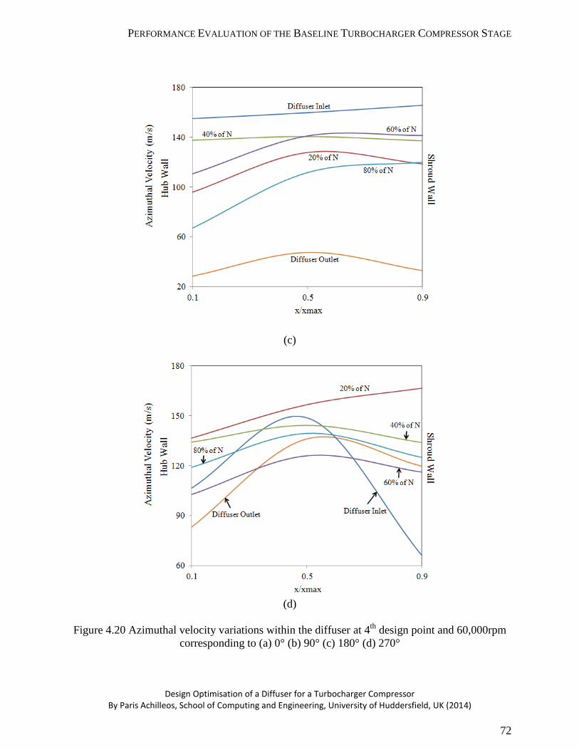


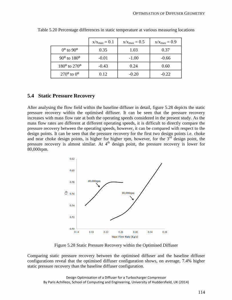


![Accornero, Franco PAGEANT Achilleos, [Chris] FREEWAY Adams, …bookscans.com/Publishers/krjohnson/defunctpages/... · 2016. 5. 10. · Daeni, Pino PAGEANT Danska, H. Lion Davidson,](https://static.documents.pub/doc/80x56/5fe6732c2dfa5734e46e8e82/accornero-franco-pageant-achilleos-chris-freeway-adams-2016-5-10-daeni.jpg)
