University of Huddersfield Repository Crosbee, David and Allen, Paul Development of a Tram-Train wheel profile for dual-operation running Original Citation Crosbee, David and Allen, Paul (2015) Development of a Tram-Train wheel profile for dual- operation running. In: 1st International IMechE Stephenson Conference, 21st - 23rd April 2015, London. This version is available at http://eprints.hud.ac.uk/id/eprint/27316/ The University Repository is a digital collection of the research output of the University, available on Open Access. Copyright and Moral Rights for the items on this site are retained by the individual author and/or other copyright owners. Users may access full items free of charge; copies of full text items generally can be reproduced, displayed or performed and given to third parties in any format or medium for personal research or study, educational or not-for-profit purposes without prior permission or charge, provided: • The authors, title and full bibliographic details is credited in any copy; • A hyperlink and/or URL is included for the original metadata page; and • The content is not changed in any way. For more information, including our policy and submission procedure, please contact the Repository Team at: [email protected]. http://eprints.hud.ac.uk/
Transcript
University of Huddersfield Repository
Crosbee, David and Allen, Paul
Development of a TramTrain wheel profile for dualoperation running
Original Citation
Crosbee, David and Allen, Paul (2015) Development of a TramTrain wheel profile for dualoperation running. In: 1st International IMechE Stephenson Conference, 21st 23rd April 2015, London.
This version is available at http://eprints.hud.ac.uk/id/eprint/27316/
The University Repository is a digital collection of the research output of theUniversity, available on Open Access. Copyright and Moral Rights for the itemson this site are retained by the individual author and/or other copyright owners.Users may access full items free of charge; copies of full text items generallycan be reproduced, displayed or performed and given to third parties in anyformat or medium for personal research or study, educational or notforprofitpurposes without prior permission or charge, provided:
• The authors, title and full bibliographic details is credited in any copy;• A hyperlink and/or URL is included for the original metadata page; and• The content is not changed in any way.
For more information, including our policy and submission procedure, pleasecontact the Repository Team at: [email protected].
http://eprints.hud.ac.uk/
Development of a Tram-Train wheel profile for dual-operation running
Crosbee D. & Allen P.D.
University of Huddersfield, United Kingdom
Carroll R.
Sheffield Supertram
ABSTRACT
This paper explores the problematic interface between a Tram-Train vehicle and two very different railway infrastructures, detailing the analysis and design process required to develop an optimised wheel profile for dual operation running.
One of the key issues in developing a dual-operation wheel profile is managing the contact conditions within the wheel/rail interface. The interface is critical not only to the safe running of the vehicle but also to maximise wheelset life and to minimise wheel-rail damage. A combination of vehicle dynamic simulations and bespoke software were used to allow the development of a new wheel profile for Tram-Train operations.
1 INTRODUCTION
The Tram-Train concept provides a dual-mode vehicle that operates as a tram on light rail infrastructure and a conventional train on heavy rail infrastructure, offering a seamless journey to the passenger into the heart of city centres and relieving capacity from mainline stations. The first Tram-Train scheme was in Karlsruhe, Germany, in the early 1990s and has spread successfully to several other European cities – but not yet to the UK.
To demonstrate that the benefits of Tram-Train can be realised in the UK, the Tram-Train pilot project was set up by the Department for Transport (DfT) with Network Rail, Northern Rail, Stagecoach Supertram and South Yorkshire Passenger Transport Executive (SYPTE) as partners. The chosen route runs for 6.5km from the centre of Sheffield on the Sheffield Supertram (SST) light-rail network before connecting with Network Rail (NR) heavy-rail infrastructure at Tinsley. From here the Tram-Train vehicle will run for a further 5.7km on the NR track to Rotherham. In order to run on both networks there are many interface issues to deal with such as signalling, platform heights, overhead line equipment and wheel/rail interaction.
Network Rail (NR) requested the support of the Institute of Railway Research (IRR) at the University of Huddersfield (UoH) to develop a wheel profile design suitable for Tram-Train operation over NR heavy-rail infrastructure and the Sheffield Supetram (SST) light-rail network. This paper discusses the challenges and the design process followed during the evolution of the wheel profile and the rationale behind the design choices that were made. The paper also describes the required design assurance which has been carried out to ensure the new profile has sufficient resistance to derailment, is compatible with switches and crossings (S&C)
and has acceptable performance in terms of wheel-rail rolling contact fatigue and wear.
2 PROFILES
There is a combination of wheel and rail profiles used on the SST and NR infrastructure, all of which needed to be considered. The following sub-sections present the various wheel and rail profiles currently in use on these two systems.
2.1 Comparison of existing wheel profiles
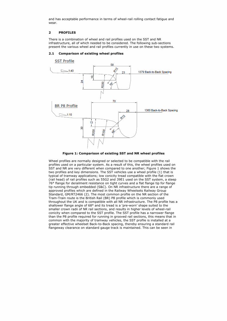
Figure 1: Comparison of existing SST and NR wheel profiles
Wheel profiles are normally designed or selected to be compatible with the rail profiles used on a particular system. As a result of this, the wheel profiles used on SST and NR are very different when compared to one another; Figure 1 shows the two profiles and key dimensions. The SST vehicles use a wheel profile (1) that is typical of tramway applications; low conicity tread compatible with the flat crown (rail head) of rail profiles such as 55G2 and 39E1 used on the SST system, a steep 76° flange for derailment resistance on tight curves and a flat flange tip for flange tip running through embedded (S&C). On NR infrastructure there are a range of approved profiles which are defined in the Railway Wheelsets Railway Group Standard, GM/RT2466 (2). The most common profile on the NR section of the Tram-Train route is the British Rail (BR) P8 profile which is commonly used throughout the UK and is compatible with all NR infrastructure. The P8 profile has a shallower flange angle of 68° and its tread is a ‘pre-worn’ shape suited to the smaller crown radii of NR rail sections, and results in higher levels of wheel-rail conicity when compared to the SST profile. The SST profile has a narrower flange than the P8 profile required for running in grooved rail sections, this means that in common with the majority of tramway vehicles, the SST profile is installed at a greater effective wheelset Back-to-Back spacing, thereby ensuring a standard rail flangeway clearance on standard gauge track is maintained. This can be seen in
Figure 1 which shows the two profiles at the correct lateral position relative to one another.
2.2 Comparison of existing rail profiles
The Tram-Train route will have a combination of new and worn rail profiles of both grooved and vignole (flat bottom) type. In order to develop an optimised wheel profile for dual-operation on both systems it was necessary to consider all the profiles that Tram-Train will encounter. Table 1 lists the installed rail profiles on the Tram-Train route.
Table 1: Rail Profiles used on Tram-Train route
Profile Standard System Rail Type
Inclination Track Type
BS80A (39E1) EN 13674-4 (3) SST Vignole Vertical S&C
1:40 Ballasted Track
55G2(41GP) EN 14811 (4) SST Grooved Vertical Embedded Track
54E1 (UIC 54) EN 13674-1 (5) SST Vignole Vertical Viaduct
BR113A (56E1)
EN 13674-1 (5) SST Vignole Vertical Ballasted Track
NR Vignole 1:20 Ballasted Track
SST Worn - SST - - -
NR Worn - NR - - -
When considering the worn rail profile shapes, the former Rail Technology Unit (RTU) at Manchester Metropolitan University compiled a report (6) on the suitability of different wheel profiles for Tram-Train. The report demonstrated that measured rail profiles of SST BS80A and 55G2 had the same worn shape and therefore only one worn rail profile for SST is considered. This is typical of ‘closed’ rail systems whereby the infrastructure sees only one vehicle and wheel profile type.
The IRR holds a significant number of measured worn NR profiles and a representative worn rail profile was selected for use in this study.
Figure 2 shows the most prevalent new rail profiles and the corresponding worn profiles found on the Tram-Train route. The new BS80A and 55G2 profiles which are installed on SST have virtually the same gauge corner and head profile giving similar contact conditions, the key difference is the keeper rail on the 55G2. When comparing the new and worn SST and NR profiles it can be seen that there is a large variation in shapes, the key differences being with the gauge corner and crown radii.
Typically as a rail wears it tends to adopt the shape of the wheels running on it, such that the NR worn rail shape is similar to a BR P8 wheel and the SST worn rail profile is similar to the SST wheel profile. This conformality is demonstrated in Figure 3Figure 3.
Figure 2: Prevalent rail profiles on Tram-Train route
Figure 3: Comparison of wheel profiles and worn rail profiles
3 PROFILE DEVELOPMENT
The Tram-Train vehicle will be the minority vehicle running on both NR and SST infrastructure. As a result, following introduction of the Tram-Train service, the existing worn rail shapes on both NR and SST will remain similar to their current shape. The design of the Tram-Train profile has therefore been optimised for the worn rail shapes on NR and SST, with the best achievable compatibility with new 55G2 (41GP), BR113a (56E1) and BS80A (39E1).
In addition, to assist in the approvals process, the profile design has also been focussed on meeting Railway Group Standard for wheelsets, GM/RT2466 (2).
The initial study conducted by the RTU considered a range of existing wheel profiles for use on Tram-Train (6). The study concluded that none of the current UK tramway wheel profiles including the current SST wheel were suitable for use on NR infrastructure due to severe two-point contact at relatively large curve radii, resulting in accelerated wheel and rail wear. However the work did find that an BR P8 wheel profile generated similar wheel-rail wear rates on SST infrastructure as the current tramway wheel profile and therefore the P8 wheel could form the basis of a possible Tram-Train profile. This is demonstrated in Figure 4 which shows the Tγ (contact patch energy – the product of creepage and creep force) generated on the tread and flange for a range of curve radii. Higher Tγ values equate to higher wear rates as shown by work carried out by British Rail Research (BRR) (7). The plots in Figure 4 for NR infrastructure show that the generated Tγ is slightly higher on the tread for the SST wheel when compared to the NR P8 and considerably higher on the flange. Plots on SST infrastructure show that the P8 and SST profiles perform in a very similar manner.
Figure 4: Tγ vs Curve Radius for SST and NR P8 wheel profiles on NR and SST infrastructure
It was therefore decided that a hybrid profile was required, based upon a combination of the SST and the P8 profile to ensure interoperability on the two systems. The profile required the following features:
P8 type geometry from flange face to tread, this maintains geometry that is compatible with NR rail profiles and avoids severe two-point contact generated using conventional tram profiles.
68° flange angle for compatibility with NR switch toes and facilitate the required 3mm of residual switch opening (RSO).
SST flat flange tip for compatibility with flange tip running through crossings in grooved rail on SST.
SST flangeback angle and position to create similar keeper/check rail contact conditions.
Cut-out in back of wheel to provide two checking faces – one for NR and one for SST.
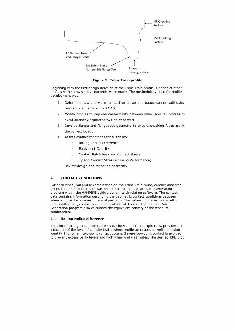
Figure 5 shows the Tram-Train profile which combines all of the required features listed above.
Figure 5: Tram-Train profile
Beginning with the first design iteration of the Tram-Train profile, a series of other profiles with stepwise developments were made. The methodology used for profile development was:
1. Determine new and worn rail section crown and gauge corner radii using
relevant standards and 2D CAD.
2. Modify profiles to improve conformality between wheel and rail profiles to
avoid distinctly separated two-point contact.
3. Develop flange and flangeback geometry to ensure checking faces are in
the correct location.
4. Assess contact conditions for suitability:
o Rolling Radius Difference
o Equivalent Conicity
o Contact Patch Area and Contact Stress
o Tγ and Contact Stress (Curving Performance)
5. Review design and repeat as necessary
4 CONTACT CONDITIONS
For each wheel/rail profile combination on the Tram-Train route, contact data was generated. The contact data was created using the Contact Data Generation program within the VAMPIRE vehicle dynamics simulation software. The contact data contains information describing the geometric contact conditions between wheel and rail for a series of lateral positions. The values of interest were rolling radius difference, contact angle and contact patch area. The Contact Data Generation program also calculates the equivalent conicity of the wheel rail combination.
4.1 Rolling radius difference
The plot of rolling radius difference (RRD) between left and right rails, provides an indication of the level of conicity that a wheel profile generates as well as helping identify if, or when, two-point contact occurs. Severe two-point contact is avoided to prevent excessive Tγ levels and high wheel-rail wear rates. The desired RRD plot
should, if possible, have a smooth transition from tread to flange contact without significant jumps which would indicate two-point contact. In addition, the gradient of the rolling radius difference plot does not want to be too great, as this would result in a high conicity wheel/rail profile combination. The conicity of the profile is important as a high conicity will provide good curving performance but will make the vehicle more susceptible to lateral instability. Although good curving performance is desirable, poor lateral stability should be avoided as it is detrimental to passenger ride comfort and also results in increased wheel and rail wear.
Figure 6 shows the RRD plots for new and worn SST wheel profiles and the Tram-Train wheel profile on worn SST rail. The new and worn SST wheel profiles provide little RRD up to the point of flange contact, at which point the RRD rises rapidly. The jump in the RRD for the worn SST profile between 6 and 7mm lateral shift is due to the way that the side worn rail profile interacts with the wheel flange resulting in the contact patch jumping up and then back down the flange. The Tram-Train wheel profile provides a higher amount of RRD on the tread indicating higher conicity and therefore better curving performance. The transition on to the flange is less abrupt than for the SST wheel profiles and does not exhibit two point contact which will help minimise rail side wear.
Figure 6: Rolling Radius Difference plot on SST infrastructure
4.2 Contact angle
The contact angle is the angle of the contact patch relative to the horizontal plane. The contact angle has been considered as a measure of flange climb derailment resistance. A steeper flange contact angle maintains a lower risk of flange climbing. Figure 7 presents a plot of contact angle for new and worn SST wheel profiles and the Tram-Train profile on SST infrastructure
The plots show that as the profiles enter flange contact, the maximum contact angle reached is equal to the wheel profile flange angle. For the current SST profile that angle is 76° and for the developed Tram-Train profiles, the angle is 68° - the same as a BR P8. The plots also show the distance over which the angle is maintained in terms of wheelset lateral shift, with a larger lateral shift being more favourable as this offers the greatest protection against flange climb.
For all of the Tram-Train profiles developed, the flange angle is reached and sustained without a significant rate of reduction in flange angle as the contact patch moves up the flange. This characteristic provides sustained flange climb protection under more demanding contact conditions.
Figure 7: Contact Angle plot for right wheel on SST infrastructure
Figure 8: Contact Patch Area plot for right wheel on SST infrastructure
4.3 Contact patch area
It is desirable to maximise the contact patch area in order to reduce the contact stress. Increased levels of contact stress can result in greater damage within the wheel/rail interface in the form of wear, Rolling Contact Fatigue (9,10) and Rail Squats (11). Higher contact stresses will cause increased levels of wear and could possibly cause plastic flow of material within the wheel and rail. The aim of this aspect of the study was to develop a new Tram-Train profile with similar or greater
contact patch areas than the existing profiles on the SST and NR systems. Figure 8 shows that although the contact patch area is slightly smaller on the flange for the Tram-Train profile, the contact patch area is similar overall to the current SST profiles.
4.4 Equivalent conicity
Equivalent conicity provides an indication of the vehicle’s curving performance and lateral stability. The conicity values of existing SST and NR wheel/rail combinations have been calculated and are used as a benchmark for the levels of conicity that the Tram-Train vehicle should be able to accommodate without increased risk of stability issues. Table 2 contains the equivalent conicity values for the different wheel/rail combinations on the Tram-Train route. It can be seen that the conicities generated by the Tram-Train profile do not exceed the maximum conicities generated by the SST and NR wheel/rail profiles.
Table 2: Equivalent Conicity values for different profile combinations
Wheel
Rail
55G2 39E1 1:40
SST Worn 56E1 1:20
NR Worn
P8 New -- -- -- 0.174 0.103
P8 Worn -- -- -- 0.264 0.163
SST New 0.338 0.083 0.024 -- --
SST Worn 0.264 0.352 0.066 -- --
Tram-Train 0.23 0.201 0.22 0.185 0.13
5 DYNAMIC SIMULATIONS
The VAMPIRE Curving Analysis program was used to assess the curving performance of all profile combinations. The simulations were carried out using a coefficient of friction of 0.45 on the tread and flange and were run at balancing speed – the speed at which the lateral forces from curving are cancelled out by the cant of the track.
The outputs from the simulations were the Tγ and the Contact Stress in the tread and flange contact patches.
5.1 Tγ
Tγ is the work done or energy dissipated in the contact patch (as defined in Section 3) and provides an accepted method of quantifying the wear at the wheel/rail interface as shown by work carried out by British Rail Research (BRR) (7). Figure 9 presents the wear function developed by BRR which relates Tγ to a rail wear rate.
Figure 9: British Rail wear function
The wear function shows that higher Tγ values equate to higher levels of wear so from this perspective it is desirable to keep Tγ values as low as possible. Figure 10 shows a typical plot of Tγ curving results for a range of curve radii. This plot shows the current new and worn SST and new Tram-Train wheel profiles on worn SST rails. It can be seen that the worn SST wheel generates much lower Tγ values than the new SST wheel on curve radii greater than 150m. The Tram-Train profile performs in a similar way to the worn SST wheel profile which demonstrates good performance on worn SST rails.
Figure 10: Tγ vs Curve Radius for Supertram Infrastrucutre
5.2 Contact stress
The contact stress calculation is linked to the contact area calculated in Section 4.3 but the calculation of contact stress takes into account the effect of the dynamic forces generated by curving and the distribution of loads between tread and flange contact patches. Figure 11 shows how the contact stresses vary with curve radius for the Tram-Train vehicle on SST infrastructure. On the right tread the Tram-Train
profile generates lower contact stresses than the new SST profile for all curve radii. On the left wheel tread the Tram-Train profile generates the highest stress on the tread out of all the profiles at large curve radii but the corresponding stress on the flange is below that of the current SST until the curve radii drops below 200m. This indicates that flange and rail side wear will be reduced when using the Tram-Train profile.
Figure 11: Contact Stress vs Curve radius for Supertram Infrastructure
6 GEOMETRIC ASSESSMENT
A series of geometric assessments were undertaken to ensure safe passage of the Tram-Train wheelset through all trackforms and S&C.
6.1 Grooved rail
When a vehicle negotiates a curve the wheelsets assume an Angle of Attack (AoA) producing a geometric effect which increases the effective wheel flange width. It is important that the effective flange width does not exceed the rail groove width and thereby ensures free wheel passage in all curves on the system. If the effective flange width is too great then both flange face and flangeback can come into contact with either side of the groove simultaneously; known as forcing of the wheel flanges in the rail groove. This scenario can pose an increased derailment risk and will also result in excessive wheel and rail wear.
The maximum effective flange width, or minimum groove width, was calculated for the maximum AoA which occurs at the smallest curve radii, 25m for SST. The calculation was performed using IRR in-house software which uses the Filkins-Wharton method to determine the effective flange width and generates a Nytram plot (12) showing the locations of the flange and flangeback contacts. Figure 12 shows the Nytram plot for the worst case - new wheels, minimum Back-to-Back spacing and maximum track gauge. The green points illustrate the flange contacts on the high and low rails and the red point the flangeback contact which would cause flange forcing. The purple point highlights where keeper rail contact would occur and hence defines the minimum groove width required to prevent keeper contact. The minimum calculated groove width for the SST system was found to be
26.7mm which is less than the 40.7mm groove width of new 55G2 groove rail. Therefore forcing of the flanges in grooved rail sections will not occur.
Figure 12: Nytram Plot
6.2 Switch and Crossing Interaction
Several methods have been applied to ensure that the Tram-Train wheelsets safely negotiate S&C. These methods have been taken from BOStrab guidelines, Network Rail standards and EuroNorms.
6.2.1 Blade vertical overlap BOStrab clause 3.10.2 (13) looks at the switch toe and requires that the wheel flange overlaps the switch toe by a minimum of 4mm. Figure 13a shows the dimensions that must overlap, H and h. Figure 13b shows the Tram-Train wheel profile located at an NR full depth and shallow switch toe with 3mm of residual opening and the dimensions H and h giving an acceptable overlap of 6.8mm.
Figure 13: a) BOStrab flange overlap b)Tram-Train profile at NR full depth switch toe with 3mm residual switch opening showing flange overlap
6.2.2 Minimum contact angle This NR Standard for ‘Inspection and repair to reduce the risk of derailment at switches’ (14), states that as a general rule, the point at which the wheel-rail contact angle reduces to 60° should typically be no less than 20-25mm below the rail head (See Figure 14a). It also mandates that contact should not occur with the switch blade at an angle lower than 60°. This is to protect against flange climb
-1000 -800 -600 -400 -200 0 200 400 600 800 1000
-800
-600
-400
-200
0
200
400
600
800
(mm)
(mm
)
b) a)
derailment at the switch toes. Figure 14b shows the Tram-Train profile on an NR switch blade. The distance to the 60° is greater than the 20mm minimum distance but the minimum contact angle does drop below 60° to 56.8°. This is however not considered a problem in this application, as the standard BR P8 profile, which has an excellent operational safety record, also fails to meet this requirement with a minimum contact angle of 50.8° under the same conditions.
Figure 14: a) Minimum contact angle b) Tram-Train profile at first point of contact with NR Full Depth switch blade showing contact angles and
positions
6.2.3 Secant contact angle Secant contact occurs when the wheel encounters an object on its route – in this case the end of the switch toe. EN 13232-9 (15) states that contact with the switch toe should not occur in the contact danger zone which is an area around the flange tip where the contact angle falls below a certain limit. This assessment protects against flange climb and switch splitting derailment.
The standard defines that the danger zone extends from the point at which the flange angle drops to 40° and extends around the flange tip, Figure 15a shows an example of a safe contact condition. Figure 15b shows the Tram-Train wheel profile located at the proposed NR switch toes with 3mm of residual opening. The ‘danger zone’ is highlighted in red and extends through an angle of 80° around the flange tip. It can be seen that the wheel flange does not contact the switch toes at any point within the defined sector and therefore the Tram-Train profile meets the requirements in this assessment.
Figure 15: a) Secant contact angle b) Tram-Train profile at NR full depth switch toe with 3mm residual switch opening showing 'Danger zone'
6.3 Check Rail Interaction
The Tram-Train profile design required a cut-out in the flangeback to provide a checking face at 1379mm Back-to-Back spacing for compatibility with SST grooved
b) a)
b) a)
rail whilst retaining a checking surface further up the flangeback with a spacing of 1360mm for compatibility with NR S&C. The cut-out extends up the flangeback to a height which was selected to ensure that the wheel profile can operate safely on SST grooved rail even when the rail head reaches its vertical wear limit.
The provision of a flangeback cut-out raises the checking face for NR infrastructure further up the flangeback, therefore NR check rails must be raised to maintain correct and safe contact conditions with the Tram-Train profile flangeback. This process requires that route gauging clearance is required for all vehicles running on the NR infrastructure as the lift takes the check rail beyond the standard NR structure gauge.
CAD software was used to determine the required check rail lift, Figure 16 shows the check rail in the nominal and raised position. The minimum amount that the check rail should be raised is 40mm to bring the vertical checking surface of the check rail in line with the NR checking surface on the flangeback.
Figure 16: NR Check rail in nominal and raised position
7 CONCLUSIONS
A dual operation wheel profile has been designed to run on Network Rail and Sheffield Supertram infrastructure. The design incorporates several features to meet the requirements of the two rail systems such as
Cut-out in the flange back to provide two checking surfaces for NR and
SST infrastructure
68° flange angle with bespoke flange toe profile to provide required
clearance on NR switch toes
Flat flange tip to facilitate flange tip running through SST embedded
switches and crossings
Tread geometry derived from the BR P8 profile that avoids hard two-point
contact, reduces wear and improves curving
The final wheel profile design is illustrated in Figure 17.
and above”, BS EN 13674-1:2003+A1:2007 4. “Railway applications – Track - Special purpose rail - Grooved and
associated construction”, BS EN 14811:2006+A1:2009 5. “Railway applications – Track - Rail - Part 4: Vignole railway rails from
27kg/m to, but excluding 46 kg/m”, EN 13674-4:2006+A1:2009 6. Allen, P. (2008) ”Support for the Introduction of Tram-Train Vehicles on
Network Rail Infrastructure”, RTU Report 81/13 Issue 2 7. McEwan I. J. and Harvey R. F. (1986), “Technical Memorandum –
Interpretation of Wheel Wear Numbers”, British Rail Research Report TM-VDY-004
8. Rail Safety and Standards Board (2012), “Railway Wheelsets”, GM/RT2466 9. Ringsberg, J.W. (2000), Cyclic Ratchetting and Failure of a Pearlitic Rail
Steel. Fatigue & Fracture of Engineering Materials & Structures. 23(9): p. 747-758.
10. Beynon, J.H., J.E. Garnham, and K.J. Sawley (1996), Rolling Contact Fatigue of Three Pearlitic Rail Steels. Wear. 192(1-2): p. 94-111.
11. Sinclair, J.C. and Allery M.B.P. (1991), “Development of a Failure Parameter for Rail Squats”, British Rail Research Report TM MF 211.
12. Transportation Research Board (2012),“Track Design Handbook for Light Rail Transit, Second Edition”, ISBN 978-0-309-25824-1
13. “Regulations on the Guidance of Rail Vehicles in accordance with the German Federal Regulations on the Construction and Operation of Light Rail Transit Systems (BOStrab) - Guidance Regulations (SpR)”, March 2004, English translation by J Snowden Sept. 2008.
14. Network Rail (2008),“Inspection and repair to reduce the risk of derailment at switches”, NR/L2/TRK/0053 Issue 5
15. “Railway applications - Track - Switches and crossings - Part 9: Layouts”, BS EN 13232-9:2006+A1:2011


![] The Smallpeice Trust Overview- IMechE February 2012.](https://static.documents.pub/doc/80x56/56649cb85503460f9497ebee/-the-smallpeice-trust-overview-imeche-february-2012.jpg)


