Page 1
University of Illinoisat
Urbana-ChampaignAeronautical and Astronautical Engineering
AAE 241
Aerospace Vehicle Design, Spacecraft SectionFinal Project Reports
Volume I
Project Groups 3 through 5
A/_Sa._- _4/55" May 1989
https://ntrs.nasa.gov/search.jsp?R=19900004947 2018-05-14T11:44:59+00:00Z
Page 2
PROJECT STINGRAE
M E 241 SPRING 1989
P r
Darrell Ahne
Deidre Caldwell
Ken Davis
Susan DelMedico
Ed Heinen
Shoeb lsmail
Carrie Sumner
UNIVERSITY OF ILLINOIS
Page 3
Table of Contents
StructuresRequirementsGeneral DescriptionPressure Vessel DesignMicrometeorite ShieldingVertical Stabilizers and Body FlapComponent LayoutThermal Protection SystemThermal Control Subsystem
Command and Data ControlDesign ConsiderationsCommunication System Configuration and DesignBreakdown of Communication Components
Attitude and Articulation ControlThree Axis Active Control SystemControl TorquesMaximum Delta VControl Moment GyrosStar TrackerSun SensorAccelerometers
Power and Propulsion SystemMission Breakdown/Power ConsumptionCircuit DiagramMass Increase with Increased KBattery SizingPropellant MassesTank SizesDelta V Calculations for Polar Orbit
Life Support and Crew SystemsCrew Size vs. Life Support RequirementsTank Sizes/PlacementCrew Volume RequirementsThreatsInteractions with other Subsystems
Mission Management, Planning and CostingPayload IdentificationVolume for Resupply MissionsLaunch Vehicle SelectionPayload IntegrationMission OutlineProgram ImplementationTestingCostingInteraction with other Subsystems
Reentry and RecoveryConfiguration AnalysisPerformance AnalysisTrajectory AnalysisThermal AnalysisLanding and Recovery Analysis
Page 4
Prelimary Design Considerations:
The study conducted under the project name STINGRAE (for Space
Transportation Integrated Resupply And Automated Evacuation System)
was designed as system intended to fill the need to rescue and supply the
space station with an adequate support for performing missions
envisioned for the year 2000 and beyond.
Because the number and type of STINGRAE missions perform in the
specified time period would have a great effect on the configuration and
effort was made to determine what the demand would be for the various
types of subsystems visualized as within the scope of project STINGRAE.
Each subsystem has specifications that must be accomplished. Seven
categories of specific subsystems were analyzed:
1. Structures
2. Communication and Command Data Systems
3. Attitude and Articulation Control
4. Life Support and Crew Systems
5. Power and Propulsion
6. Reentry and Recovery Systems
7. Mission Managament, Planning and Costing
Specific structure requirements include: Placement of components
to meet conflicting requirements, mass/inertia configurations, verify
launch vehicle compatibility, drawings of layout.
Communication and Command Data Systems requirements include:
Data rate estimates, antenna sizing/placement, geometry for antenna
pointing throughout mission, rendezvous and docking, interations with the
other subsystems.
Attitude and Articulation Control requirments include: Delta-V
required for minimum maneuver scheme, attitude control modes, selecton
and placement of AACS sensors, scanning and pointing requirements
Page 5
implementation, fuel requirements/sizing, payload loading and unloading
and interaction with other subsystems.
Life support and crew subsystems requirements include: Crew size
vs. life support requirements, tank sizing, crew volume reqm'ts, threats
(reasons for leaving space station) and interaction with other subsystems.
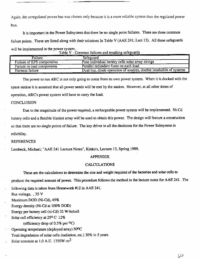
Power and propulsion requirements include: Power estimates,
selection of batteries, solar cells, fuel selection/tank sizing, thrusters
selection/configuration and interaction with other subsystems.
Reentry and recovery include: Size/shape, placement of
components, dynamic and control, crew g forces, recovery method and
interaction with other subsystems.
Mission management and costing include: Mission delta-v required,
orbit insertion altitude and velocity, mission timeline and mission
planning effect on subsystems.
These requirements served as the basis for the formulation of the
STINGRAE spacecraft design.
Page 6
STRUCTURES
Requirement_
The main requirement for the structures subsystem in the
request for proposal (RFP) submitted to group 3 is to design a
vehicle structure capable of carrying supplies to and from Space
Station Freedom repeatedly and bringing back humans (in an
emergency) and waste to earth. While it is hoped that humans will
not need to use the vehicle as a means of evacuation it must never
the less make provisions for them.
To satisfy this, more specific requirements appear. For
example, the vehicle must be capable of withstanding
pressurization, it must protect itself against hazards encountered in
launch, orbit and reentry, such as extreme thermal and structural
loads. It must be reusable and safe and use tested reliable
equipment.
STINGRAE is the response to this request.
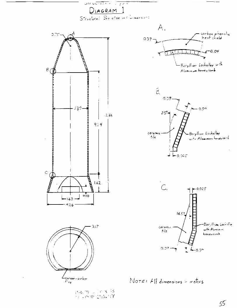
General Description of STINGRAE
The Space Station Integrated Resupply and Evacuation System
(STINGRAE) is shown in figure 1. It consists of an inside wall, a
support structure, an outer micrometeorite shield covered in
reusable surface insulation, vertical stabilizers 1, a body flap 2, a
docking hatch 3, landing gear, and a small wing structure 4. The
overall length is 17 m, the width is almost 5 m, and the height of
the vehicle is approximately 3 m. STINGRAE is constructed mainly
Page 7
of conventional aluminum and covered in reusable surface
insulation (RSI).
Pressure Vessel Design
The decision to pressurize the entire craft arose mainly from
the logistics requirements for the vehicle. Approximate ratios of
2:7 for unpressurized mass : total mass and 1:2 for unpressurized
volume: total volume made pressurization of the whole vehicle seem
the most practical. The advantages of having a smaller pressurized
area and a separate unpresssurized area were negated by the
difficulties that arose regarding the distribution of space and
therefore the construction of the vehicle to such a changeable
factor. Since it was determined that all items in the projected
payload would easily fit through the Space Station Freedom's hatch,
it was decided that the entire cargo of the vehicle would be unloaded
through that hatch and distributed through the space station's
facilities.
The calculations for STINGRAES pressure vessel interior contain
some assumptions they are as follows:
1. assumed cylindrical pressure vessel shape with a
diameter equal to the widest part of the vehicle (This is over
designing, but for lack of a more complex analysis this choice was
felt to be prudent. )
2. used a yield strength of 2.89 (108) N/m 2 for aluminum
2024-T3. This value varies with the temperature of the material of
the material and drops off rapidly for temperatures over 450 K, but
Page 8
the thermal protection system (TPS) will assure that this
temperature is not exceeded even during reentry heating.
3. assumed a safety factor of 2.5. Given the completely
reliable and tested nature of the material used and the overdesigning
mentioned in part 1 this was considered to be sufficient.
Using the equation below it is possible to calculate the pressure
vessel thickness for the given conditions:
Y.S/(s.f.)= p(ri + t/2)/t
where:
Y.S = the yield strength of the aluminum (=2.89 (108) N/m2)
s.f. = safety factor = 2.5
ri = radius of pressure vessel = 4.57m
p = is the pressure designed for (=1.013(105)N/m 2)
The thickness of the pressure vessel wall was found to be 0.2001.
Micromete0rite Shieldinq
Due to the length of time each vehicle will spend in space a
major concern is insuring the structural integrity of the spacecraft
during micrometeorite impacting. The micrometeorite shielding
must be as thin and light as possible while still guaranteeing the
pressure vessel will not be penetrated and spalling is minimal. The
main considerations for the design of a micrometeorite shield are
the diameter,mass, and velocity of the mircometeorites to be
Page 9
expected, the material properties of the inner and outer walls of the
vehicle, and the spacing between these walls.
Designing a single-wall spacecraft for a high probability of no
perforations for a large area over a long time would necessitate an
unacceptably large mass and multiwall systems have been shown to
be less efficient than dual walls. It has been found through
experimentation that the optimum design of walls for
micrometeorite protection can be predicted with the following
equation:
V =12.566 (1/E)(Str)(C)[(1-v)/(3+3v)] -5 (pd/m)2S 2 (ti)(to)
where: V=velocity of micrometeorite (km/sec) (avg. V=25 km/s)
m= mass of micrometeorite (gm) (=.0178 gm)
d= diameter of micrometeorite (cm) (= 1 cm)
v= Poisson's ratio of sheet material (=.33)
p= density of sheet material (gm/cm 3) (=2.77 gm/cm 3)
Str=critical stress of sheet (psi) (=42,000 psi)
E= Young's Modulus (psi) (=10.6(106) psi)
C= velocity of sound in sheet (km/s) (=5.140 km/s)
ti= thickness of pressure vessel (cm) (=.2001 cm)
S= sheet spacing (cm)
to= thickness of outer shield (cm)
Page 10
OUTER SHIELD THICKNESS VS_ WALL SPACING
outer shield
_hickness
(cm)
IZJt
!1,-,J
J
4
t]I
,4J
4
!I
2!I
!i
10
i
i
0,, ,_e-_Ignpoint:I
k ,b I
_-_._,._ ......t i I I I I I l
Z 4 6 8 t0 t2 !4 IE,
!
1? 20
vail spacing (cm)
C.ie-_!._qr_:-;e] ecti orl f,-_r- arl inr!er- ',f,,,_-_l]of thi c:k r! e '.-;:-: ti =.;-00 t crrl is:
t ,-,- I _"tF,¢) ,_-:Irl _Jt _ ,:;E,::_F: l r-!!_; t-_f '.-_-;= i r', c:m.
F,I_,,'e- :_
Page 11
Figure 2 shows a comparison of sheet spacing vs. thickness of
outer wall. The desired design minimizes both the spacing between
the walls and and thickness of the outer wall (and therefore the
mass). The design value is a spacing of 10 cm and an outershield
thickness of .1065 cm.
Vertical Stabilizers and Body Fla0
The vertical stabilizers on the back of the vehicle, each
consisting of a structural fin surface, a rudder/speed brake
assembly, a tip, and a lower trailing edge, are constructed of
aluminum and covered with a thermal protection surface. The rudder
splits vertically into two halves to serve as speed break during the
landing phase. The back body flap, also constructed of aluminum, is
designed to provide some thermal shielding for the back end of the
vehicle during reentry and provides pitch control during the
atmospheric flight phase following reentry.
Comoonent Layout
The five subsystems having components to layout in STINGRAE
are; power and propulsion, life support, command and data control,
attitude and articulation, and reentry. On the following diagram the
positions of the largest, heaviest items, having the most influence,
are shown. The main objective in the positioning of components is
to balance STINGRAE. The elements were laid out through the
program INERT. This program takes into account the moments of
inertia and centers of mass of each individual component and the
outerhull of STINGRAE itself and calculates a center of mass and
Page 12
c_L
r"-/
J
L_
L_
L_
Page 13
moment of inertia for the entire vehicle. The heaviest components
have the most influence on the positioning of the center of mass;
therefore they were used at opposite ends of the vehicle to balance
each other out (i.e. the fuel tanks for propulsion are in the back
while the life support tanks were kept in the .front.). The variation in
payloads make them impossible to specifically layout, so the
optimal configuration for the vehicle puts the payload area as much
in the center as possible.
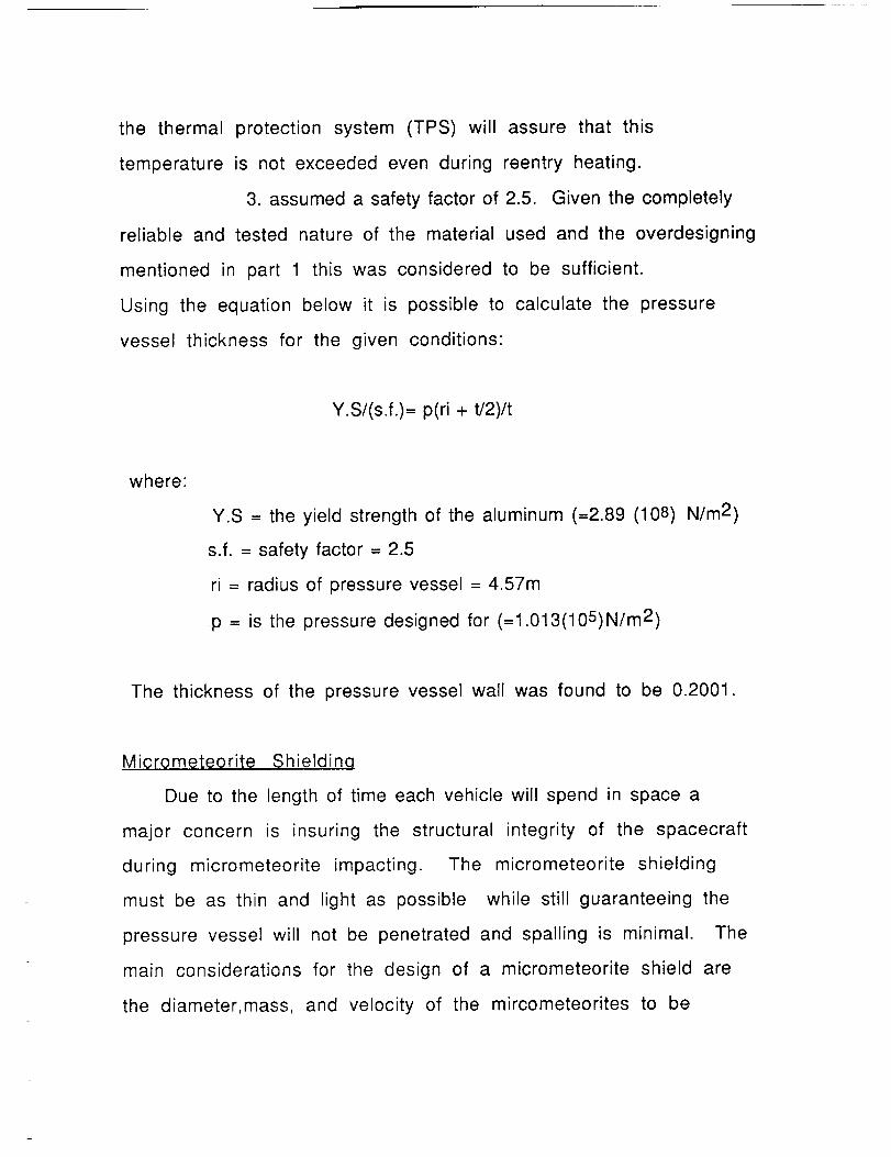
Therma, I Pr0t_¢ti0n System
The thermal protection system (TPS) consists of the external
heat shielding on the vehicle to protect the structure from excessive
reentry heating. The optimal TPS minimizes the size, mass,
complexity, and cost of the system, and maximizes ease of
application, reliability, durability. To achieve this the TPS is
composed of several different types of shielding, each one the
optimum material for its temperature range. The minimum
shielding must protect the primary structure to 450 K. The expected
temperature of a craft is dependent on the outer mold line geometry
and reentry velocity. For example sharp leading edges require the
highest temperature shielding and the smooth upper surface can
accept the lowest temperature shielding. Below is a diagram of
STINGRAE ; the shaded areas represent the minimum type of
shielding the ship will require for expected (approximate) surface
temperatures. These three types of shielding have been studied as
alternatives to the system used by the space shuttle.
Page 14
\ \ \ \ ,,
///
r_\
--\ \, \ \
k_///
\.
,_rl,/
, \ I
O-
D "3 "3 C5
Page 15
The titanium multiwall panel (figure 4) , for up to 811K, is
constructed of alternating layers of flat sheets of foil-gage
titanium and dimpled foil gage sheets, diffusion-bonded to produce
an integral prepacked tile complete with attachments.
The prepackaged superalloy bimetallic sandwich (figure 5), for
up to 1255K, consists of fibrous insulation encapsulated by inner
and outer panels, which are connected by a foil gage beaded sidewall.
The advanced carbon-carbon (ACC) standoff panel (figure 6), for
areas above 1255K, is orthogonally reinforced with carbon-carbon
ribbing and stands off the skin of the vehicle on posts. The effect is
to prevent the buildup of excessive thermal stresses and strains.
Although these materials provide a considerable weight savings
over the materials used in the space shuttle program and are
therefore quite an improvement, it should be possible with further
research to improve even these materials substantially.
/
OF POOR _UAL_TY
Page 16
OF POOR QUALi*='_
Bavone_
In¢onel
tnconel
630ram
1248 In }
Oetcri_tlon Mater,d (ram _d _n,)
/__ACC Pinet Coated ACC Typ 1.78 (0.0701
P_k_
P_ ! Used l:or ADOhc,it:r_n'. Below _ 36_ K I_O_F )
_,ze
16 PWl
S_H, Alumm= 27 8 I1 09)
(1 74 K_) m3_
/_fo (_,_,t t 305(0¸120)
(0 ¢3 K,! m_)
14 _J_x_ts C_umt_um 275x I0.187 x 1.7¢_)
44 4
3 S_on_,v CP),,ml_,m 4 75x (0 187 • 1¸751
44 4
1_ YO 40 I_. Ct AI Suo_)rt POSfS
0 91 • 091 _n J
ITh,ckt_e_s 1366 K to 1755 K [2.0OO ° - 2,700°FI
We,qt_l 11 3 Kg'm2 '2.31 t)sll
Page 17
Thermal Control Subsystem
The thermal control subsystem (TCS) consists of the equipment
required to maintain thermal control of all areas inside of the
spacecraft outershield. This control should apply during all mission
phases; including launch, earth orbit, space station docking and
reentry. The TCS must be capable of:
1. radiating the excess internal heat generated by crew
presence and onboard systems operations.
2. shielding the spacecraft's inner systems from external
heating due to reentry, solar flux, albedo flux, and earth thermal
radiation.
3. maintaining a "shirtsleeves" environment inside the
spacecraft during periods when craft is in shade.
The thermal load relationship is:
Qsol + Qalb + Qearth + Qint = Qrad
where,
Qsol = heating due to solar flux
Qalb = heating due to earth reflected solar radiation
Qearth = heating due to earth thermal radiation
Qint = heating due to internal spacecraft systems
Qrad = heat loss due to radiation
Page 18
The outside structure of STINGRAE will be painted black on the
leading edges and bottom for maximum radiation during reentry, and
white on the rest of the surface to reflect the majority of solar
radiation.
The amount of heat generated inside STINGRAE will vary
according to number of crew members, activity of systems, and
length of time spacecraft is occupied and active. This transient
heating will be controlled in part by by the presence of a thermal
capacitor (TC). The TC will be looped through a heat pipe system
circulating throughout the ship. This heat pipe system will transfer
heat from warmer to cooler regions of the ship by means evaporation
and condensation of ammonia in aluminum pipes. The primary
function of the TC is to assist in providing a steady-state thermal
environment for the spacecraft by alternately acting as a heat
source or sink. During times of excessive internal heating the" TC
will absorb much of the heat in the loop and return it during cooler
periods.
Evo porotor Condense r
Heat _n Vapour flow Heat out
Page 19
In the event that the internal thermal loads exceed the
capabilities of the heat pipe/TC combination the system will be
linked to a radiator panel located on the sloping back face of the
vehicle between the vertical stabilizers. When not in use the main
panel will be covered by another panel with reentry shielding on the
outside and a radiative surface on the inside. This outer panel will
be hinged at the top and swing out to a vertical position thereby
increasing the surface area of the radiator by a factor of two. These
inner panels will be shaded from solar flux, albedo flux, and earth
thermal radiation by the vertical stabilizers on either side and the
back of the outer panel itself.
Reentry heating is the highest thermal load the craft will be
expected to experience. The thermal protection system is capable of
shielding the outer hull of the spacecraft to about 450K (above this
temperature the yield strength of aluminum drops rapidly). To keep
the environment of the spacecraft from overheating due to this
temperature the inner wall must be insulated. Customarily,
multilayer insulation (MLI) also called the "thermal blanket" is used.
It is made up of several layers, each acting as a low emmitance
shield separated by low-conduction spaces., for example, layers of
Mylar and Kaptan foil each almost .25mm thick aluminized on one
side. A typical ten layer blanket with a total thickness of 5mm
would be equivalent to 500mm of conventional insulation.
Page 20
REFERENCES
1. Bauer, Paul, and Collicott, Howard, Entry Vehicle Heatina
and Thermal Protection Systems , Progress In Aeronautics and
Astronautics , vol 85.
2. Cooper, Paul, and Holloway, Paul, The Shuttle Tile Story,
Aeronautics and Astronautics.
3. Hays, D. , "An Assesment of Alternate Thermal Protection
Systems For The Space Shuttle Orbiter", NASA CR 3548
4. Madden, Richard, "Ballistic Limit Of Double-Walled Bumper
Systems", NASA TN D-3916.
5. Williamson, Mark "Spacecraft Thermal Design", Physics
Technology, vol 18 (1987).
6. McGraw-Hill Encyclopedia of Science and Technology, vol 17,
6th edition, (1987).
7. Lembeck,Micheal, " note sets" ,Kinko's, (1989)
Page 21
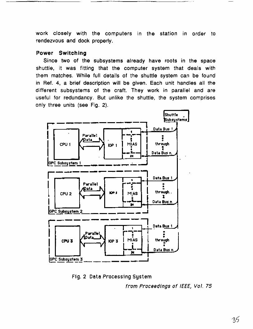
ON BOARD COMMUNICATION SYSTEMS
Desian Considerations. Functional requirements for project
STINGRAE communications system include collecting telemetry from the
subsystems, sending telemetry to the ground , command power switching,
sending commands to the subsystems and crew support avionics. The
primary function is to transmit data back to the earth. The three basic
forms of this data are: scientific, engineering (which includes
spacecraft's health), and commands.
Some STINGRAE missions would require engineering and scientific
information-gathering. It is necessary to obtain voluminous amounts of
data on the condition of the spacecraft, astronauts or cargo, and the
performance of the subsystem. In the design of the performance of the
system telemetry will be sent to the ground. Automated docking with the
space station will be controlled by an on board computer.
Considerations for design also include compatibility with the
tracking and data relay satellite system (TDRSS). TDRSS consists of two
communications relay satellites, TDRS-east and TDRS-west. These are
positioned in the geosynchronous orbit approximately 41.0 W and 1710 W
longitude, respectively. The TDRSS spare is located at 83 ° W longitude.
The TDRSS relays signals between the ground station, (in White Sands, New
Mexico), and orbiting spacecraft and user control centers, below 12,000 km
above the Earth. 1 Since the space station is located between 290 and 430
km, the STINGRAE should be compatible with TDRSS. Refer to figure 1, for
STINGRAE's compatibility features with TDRSS.
In addition to compatibility with TDRSS the system must be
standardized within itself. This standardization comes from the
requirement for versatility due to the variety of missions whether it be
Page 22
71 °vJ
STINGRAE COMPATIBILITY WITH THE TDRSS (FIG. I) _
Page 23
transporting cargo or scientists. It was first required the STINGRAE would
maneuver and rendezvous with orbiting platforms, but because of too high
&Dv requirements in the transfer of orbits, this required communication
capability was dismissed. (See propulsion and power for further details.)
Standardization with the system, however, makes different parts of the
system serve as backups for each other making the system reliable.
Communication System Confiauration and Design. A major
question to be resolved in the design process is of which band or antenna
configuration is optimal for STINGRAE's performance. Using data from the
Apollo missions and the Space Shuttle's use of TDRSS, which most space
communications of this day use, the best system for STINGRAE's
requirements were chosen.
Like Apollo, STINGRAE will use a VHF Radio link for communicaiton
and telemetry. For near Earth orbits this system can be used until the
s-band system is applied. This system also provides a secondary back up.
Although not a requirement, the VHF system could be used for a radio
communication link with an extravehicular astronaut (EVA) with direct
ground station links. The VHF system is used in conjunction with s-band ,
phase modulated (PM), frequency modulated (FM), radio links with ground
stations. STINGRAE will have four quarter - wave monopole whip antennas
located in different areas of the spacecraft and will be offset to provide
near-omnidirectional coverage. Figure 2 illustrates a standing wave on
quarter wave antenna.
Zir, " \GI_OUI,,ID PLAN -_
Figure 2: A standing wave on quarter - wave antenna. 3
Page 24
The spacecraft will use this VHF system in close range ground
station passes. The VHF system has a 5 watt output and a frequency of
296.8 MHz. 2 This system also provides communications while landing.
Landing communication frequencies need only be from 150 to 700 MHz,
which appear to be a good compromise for inexpensive systems that do not
need more accuracy than a nautical mile, (1.85 km). (See Mission
Managament and Planning for futher details on costing.)
Since the Apollo, the s-band direct ground station link system has
been upgraded. The s-band direct uplink provides 32- kilobit delta -
modulated voice channels and a data (command) channel. The resulting
uplink rate to STINGRAE is 72 kilobits per second.
The s-band direct to ground stations downlinks, 2, 32- kilobit
digital voice channels with delta modulation. Downlink also provides 128
- kilobit telemetry, which results in a time-division-multiplexed data rate
of 192 - kilobits per second. 2
The Space Shuttle uses two separate radio frequency links though
the tracking and data relay satellites. A s-band link with low - gain
antennas can be used. (Low gain causes a wider band width, therefore,
this is omnidirectional.) When the power is increased a new k-band link
with even greater capability than the s-band link can be used. For
STINGRAE's purposes, however, the high power antenna, the k-band will not
be necessary although, could be added if STINGRAE's capabilites ever
needed to be extended. Like the space shuttle, the STINGRAE will use a low
power s-band antenna which acts as an omnidirectional type antenna can
be sent to TDRSS' 3.81meter, (12 1/2 ft.), s-band dish. This particular set
up can be operated in a excess distance of 40,744 km or 22,000 nautical
miles by using STINGRAE's .9 meter , (3 ft.), s-band antenna. The space
shuttle ranges in transmitted power from 10 watts to 100 watts on the
Page 25
low power, s-band system. The STINGRAE will transmit a maximum power
to TDRSS of 100 watts. The s-band link antenna receives and transmits
telemetry , voice and commands. The schematic in figure 3 shows the
distribution of data through STINGRAE's antenna components. 4
XMIT
GLEC
Tv.A_S_o_4OB'_I__.._
Figure 3 • Schematic of antenna distribution. 4
The s-band forward link mode consists of one 24 kilobit, delta
modulation voice channel plus 8 kilobits of encoded communication data.
The s-band return link consists of two, 32 - kilobit, delta modulated voice
channels and 64 kilobits of phase coded modulation telemetry. To show
the entire component layout of STINGRAE's communication and control
systems refer to figure 4.
STINGRAE antenna design required to cope with the effects of
thermal protection system (TPS) tile, overlays the flush mounted antennas.
This tile is subject to the wear and tear of repeated atmospher.ic reentries
since each STINGRAE will fly many missions to and from the space station.
(See structures for further detatils of TPS.)
The docking mechanism of STINGRAE will be compatible with the
space station docking adapter. STINGRAE will use an optoelectronic
docking system which uses light emitters, sensors and microcomputers to
automatically control the approach of the spacecraft The range of the
automated docking is from the distance of about 1 km to and few
centimeters. 5 (See Attitde and Atriculation Control for details of
controlfing STINGRAE.)
Page 26
£ - 6,_,._D ,'s..,,j.-[e-_.,_,_
STINGRAE COMPONENT LAYOUT
FOR COMMUNICATION AND CONTROL
Page 27
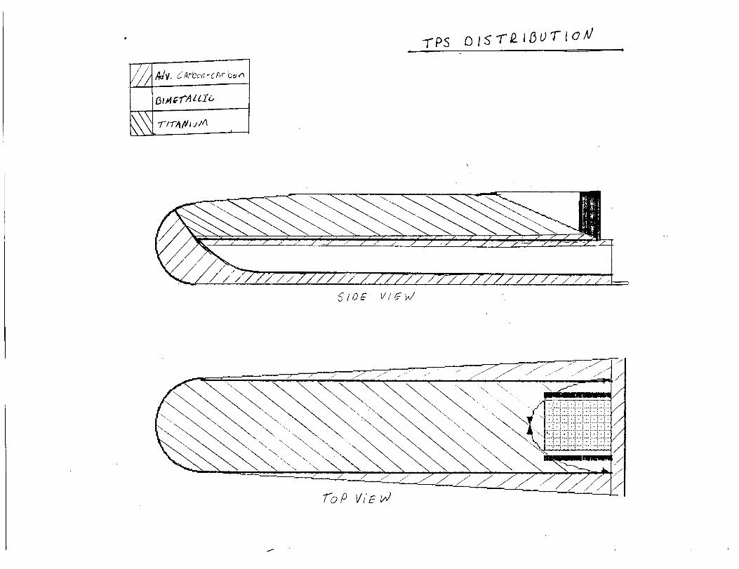
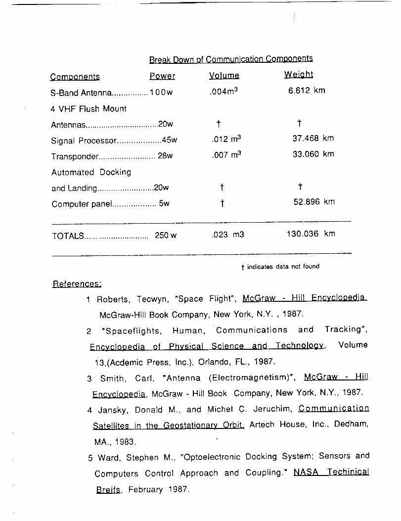
Break Down of Communication Com aonents
._ Power
S-Band Antenna ................ 1 0 0 w
4 VHF Flush Mount
Antennas ................................. 20w
Signal Processor ................... 45w
Transponder ......................... 28w
Automated Docking
and Landing ......................... 20w
Computer panel ................... 5w
Volume Weiaht
.004m 3 6.612 km
t t
.012 m 3 37.468 km
.007 m 3 33.060 km
1- t
t 52.896 km
TOTALS ............................. 250 w .023 m3 130.036 km
References:
1
t indicates data not found
2
Encvclooedia of Physical Science and Technology,
3
Roberts, Tecwyn, "Space Flight", McGraw - Hill Encvclooedia.
McGraw-Hill Book Company, New York, N.Y. , 1987.
"Spaceflights, Human, Communications and Tracking",
Volume
13,(Acdemic Press, Inc.), Orlando, FL., 1987.
Smith, Carl, "Antenna (Electromagnetism)", McGraw - Hill
Encyclopedia, McGraw- Hill Book Company, New York, N.Y., 1987.
M., and Michel C. Jeruchim, 0ommunication
Geostationary Orbit. Artech House, Inc., Dedham,
4 Jansky, Donald
Satellites in the
MA., 1983.
5 Ward, Stephen M.,
Computers Control
Breifs, February
"Optoelectronic Docking System; Sensors and
Approach and Coupling." NASA Techinical
1987.
Page 28
ATTITUDE AND ARTICULATION CONTROL
STINGRAE
The STINGRAE's attitude control system has certain
requirements. These are control of the spacecraft's attitude,
pointing device control, and payload loading and unloading.
To control the attitude, STINGRAE's system will consist of
four major functional sections. They are sensing, logic, actuation
and vehicle dynamics. The sensing function determines the
spacecraft attitude. The logic programs the electronic signals in a
correct sequence to the torque producing elements, which, in turn,
stabilize the spacecraft about its center of mass. The resulting
motion is then sensed by the vehicle sensors which thus close the
loop of the STINGRAE's attitude control system. 2
COMMANDSSENSING LO_C ACTUATIOI' t-'-- DYNAMICS
The basic type of attitude control will be provided by the
STINGRAE's three axis active control system. This system consists
of two main classes. One is the mass expulsion, which is pure jet
system and the other is a momentum exchange system, which
consists of control moment gyros and pitch wheels. The STINGRAE
will use an integrated version of both of these systems to
compensate for the internal and external torques. An integrated
2
Page 29
2
system thus will require a logic that is capable of coordinating the
efforts of both of these systems and therefore this vehicle will
demand the latest in computer science technology. External torques,
mentioned above, arise through the interaction of a vehicle with its
environment. Some type of external torques are gravitational,
aerodynamic, meteorological impact, and radiation. Calculation of
external torques requires a specification of both vehicle properties
and of the space environment within which the vehicle is situated.
Internal torques, on the other hand, are caused by fuel sloshing,
control jets, and the motion of the crew. 1
In addition to correcting for the above perturbations, an
attitude control system will allow the spacecraft to be oriented or
rotated on automatic command into a specific direction to permit
the pointing of instruments and docking with the space station.
These maneuvers will require very accurate application of small
torques.
The STINGRAE's attitude has to be controlled about three
mutually perpendicular axes, each with two degrees of freedom
giving a total of six degrees of rotational freedom. In order to apply
a true torque it is necessary to use two thrust chambers of exactly
the same thrust and equal start and stop times, placed an equal
distance from the center of mass. In order to get the maximum
torque, the thrusters will be placed at maximum distance from the
center of mass satisfying the equation T=R x F. Where the T is the
torque produced, R is the distance from the center of mass and F is
Page 30
3
the force produced by the thruster. There is a minimum of twelve
thrusters required in this system, but with STINGRAE's geometrical
design, ten thrusters in front and ten in the back of the vehicle will
be used. The placement of the thrusters is shown in figure (3).
Control torques in STINGRAE's active attitude control system
will generally be obtained from a cold gas. The main reason for the
use of cold gas is due to safety requirements. The cold gas system
will use an inert gas of nitrogen stored in a high pressure vessel
with initial pressure up to 400 atmospheres. The main reason the
nitrogen was chosen was because it offered the best theoretical
specific impulse vs. density ratio. This is illustrated on the graph in
figure (1). The gas will be passed through one or more regulators so
that the thrusters operate at nearly constant pressure. The thrust
range will be between .01 to 5 Ibs anti will provide a specific
impulse of 60 to 80 seconds. 7
The maximum Delta-V required for STINGRAE in its flight was
assumed to be .1 m/s and by using the equation •
P=W ( exp ( Delta-v ( g x Isp ) -1 )
Where the P is the propellant required, W is the weight of STINGRAE,
and g the acceleration due to gravity. For thirty maneuvers and a
safety factor of 1.5 the total propellant of nitrogen was estimated
to be 130 kg. The propellant will be stored in four high pressured
tanks and the placement of the tanks in the vehicle is in fig(3).
The other half of the active system will consist of the
momentum exchange system. In this reaction wheels or control
7
Page 31
4
moment gyros could be used. The STINGRAE will use the control
moment gyros because control moment gyros compared to reaction
wheel offers more torque capability with lower power consumption,
as well as lower weight and size for the same performance
capability.
A cluster of three control moment gyros will be used to produce
torque in pitch, roll and yaw axes. The reaction torque exerted by
the control moment gyro rotor on the gimbal is :
T= dH/dt-W x H
Where the T is the torque produced, W is the angular velocity of the
control moment gyro and H is the total momentum. The amount of
torque produced will be between .01 to 10^3 ft-lb. 2 A total attitude
with control moment gyro system is shown in figure (2).
Attitude referance for the STIGRAE will not employ Euler or
gimbal angles. The orintation of the spacecraft body to the
referance coordinate system will be specified by a nine element
direction cosine matrix. A four-element equivlent quaternion is
extracted is used from this matrix and the flight control equations
and coordinate transformations are formulated exclusively in terms
of quaternions. The quaternion formalism was adopted for use
because it offers computational efficiencies in terms of memory
usage and execution time as well as a convenient physical
interpretation of the spacecraft. 3
Selection and placement of sensors:
Page 32
5
During the STINGRAE's mission it will be necessary to
determine the vehicle's attitude relative to an inertial frame of
reference. The two type of sensors chosen for this are the rate
sensors and attitude sensors. Looking at the attitude sensors the
STINGRAE will contain the star tracker. The star tracker chosen is
the Bal Aerospace Systems Divisions' Standard Star Tracker. It is
chosen because it offered versatility, high sensitivity and flight
proven design. The tracker incorporates all the landmark features,
plus the convenience of a self contained power converter, digital
position outputs, and several performance options which increase
its utility. Its combination of large field of view and high
sensitivity enable it to detect and track stars in any portion of the
sky, thereby placing no constraints on spacecraft orientation. This
tracker is equally useful for closed loop attitude control or star
field mapping for precise attitude determination. 1 The placement of
the tracker is shown on figure (3).
Another type of attitude sensor on the STINGRAE will be the sun
sensor. This sensor will be used for backup in case of failure of star
sensor. The specific type chosen is the Digital Sun Sensor. This
sensor produces a digitally coded output that can be used directly by
the attitude determining electronics. This sensor uses a number of
solar cells arranged in a digital code form. This sensor has given
high sensitivity and a field of view ranging from several arc-
minutes to 128 by 128 degrees and resolution of less than an arc-
seconds to several degrees. 1
Page 33
6
The rate sensors on the STINGRAE are made of fiber optic gyros.
These gyros are still in research stage but before 1994 these gyros
will be able to perform the same sensing tasks as the traditional
mass gyros and the laser gyros available in the market today. The
main reason this type of gyros is chosen over its competition is that
it offers some great advantages. These advantages are its small
size, ruggedness and the prospect of modest cost. As a "strapdown"
device it does not require expensive gimbaled mounting system and
it is free of low-rotation-rate-lock in that causes other gyro types
to produce false zero outputs. 6
Accelerometers. During the ascent portion of the space
vehicle's flight, it will be subjected to large forces caused by the
thrust of the propulsion system and by aerodynamics lift. These
forces must be measured to provide guidance information and keep
the maneuvers of the vehicle within safe limits. The accelerometer
is a device which is capable of measuring these forces applied to it.
Since it is necessary to know the forces acting along all three axes
of the spacecraft, three accelerometers mounted along orthogonal
axes will be used. The type used will be the quartz resonant
accelerometers. It employs a proof mass suspended from dual
double tuning-fork, fabricated on a quartz substrate using metal
film deposition techniques. This yields a design whose performance
is relatively unchanged by environmental effects. 6
The payload loading and unloading in the STINGRAE basically
will be done manually. All the payload taken up will be able to fit
Page 34
7
through the docking adapter hatch. There is an assumption that
there is a lift arm attached to the space station and for heavy
objects this arm maybe used.
In summary, the STINGRAE spacecraft will be attitude-
stabilized by a three axis active attitude control system utilizing an
integrated on-off jet actuators and momentum exchange of control
moment gyros. The sensing units of gyros and trackers will give a
sensing rate of internal and external torques and will provide other
necessary attitude data. The total system is shown in figure (4).
Reference
1. Chety, R. D., Satellite Technology and Its Application, TAB Book
Inc., Blue Ridge, PA., 1988.
2. Chobotov, V. A., Space Attitude Dynamics and Control, Northrop
University, Spring 89.
3. Culp, R. D., Edward J.B., Doffoh W. E., Guidance and Control 1982,
Vol 48, Univelt Inc., San Diago,1982.
4. Hughes, C. P., Spacecraft Attituqle Dynamics, John Wiley and
Sons Inc., Canada, 1986.
5. Irish, A. L., Space RendezvQu_ Rescue and Recovery, Western
Periodicals Company, North Hollywood, CA., 1963.
6. Philip, J. K., Aviation Week and Space Technology, McGraw-Hill
Publication, February 13,1989.
7. Sutton, P. G., Rocket Propulsion Elements, John Wiley and Sons
Inc., New York,1949.
Page 35
Data from "Untitled Data #1"
1O0 300
80
o
E
40
20
N
200
IO0
-o,-o
0o 200 400 600 800 1000
0
1200
density kg/m3
F;9 3_
Page 36
o t
_n
-n_
=
t
0 0 m
r
....
°...
.•
.
Page 37
0_
Uo.30I
o
,
0
Z
00
Page 38
Stingrae Total Attitude Control System
CONTROL
MOMENT
GYROS
FORCE
_IACTUATORS
PATH-
CONTROL
LOGIC
POSITION
SENSORS
\m
/
/
FORCE
TORQUECONVERSIONS
_.iiI CONTROL
I MOMENTGYROS
TRANSLATIONAL
CONTROLLED-ELEMENT
DYNAMICS
PERTURBATION
FORCES
PERTURBATION
TORQUES
ROTATIONAL
CONTROLLED-ELEMENT
DYNAMICS
TORQUE
ACTUATORS
ATTITUDE
CONTROL
LOGIC
ATTITUDE
SENSORS
REF.
PATH
AND
ATTITUDE
I
I
REFERENCE 2
Page 39
Power
The power system of STINGRAE is required, by the RFP, to meet
certain specific and derived requirements which are: to meet all
subsystem power request and to do so with a system protected
against single failure destruction, to identify levels of power
consumption throughout the mission including peak consumption and
space station power taxation, and to be low cost, simple, and light
weight.
In response to these constraints, the power system of STINGRAE
is as follows. The power system consists of four source
components which perform five individual operations, each of which
is dependent upon mission time. The mission divisions are as
follows: launch to separation from Titan IV, separation from Titan
IV through rendezvous with Space Station Freedom, attachment
with Freedom, separation from Freedom to final orbit insertion,
reentry through final taxi. Storage batteries provide two of the four
power sources while the other two sources are externally provided,
the Titan IV and space station Freedom.
Just before launch, the entire power system will become
independent of ground supply and from this point until just before
separation, the Titan IV will supply "stand-by" power to the
attitude control system and full power to the life-support system
of STINGRAE (see figure 20). Seconds before separation the primary
Page 40
power system will become operable and fully activate the attitude
control system.
The primary source of power originates from a collection of
Silver Zinc (Ag Zn) cells. These cells form the main battery
system which supplies the power from Titan IV separation through
rendezvous with Freedom. This main battery system, after
recharging at Freedom, also supplies the power from space station
separation to final orbit insertion. The system will deliver a
maximum power of two kilowatts per hour for sixteen hour at a
depth of discharge of eighty percent. Since this time interval will
far surpass all estimates on elapsed time from station separation
to landing, it therefore will serve as a safety buffer. In the event
of a station separation without a reentry, i.e. an emergency
evacuation and later return to station, it is possible to maintain
two kilowatts per hour of power for twenty four hours but this will
require the batteries to completely discharged.
Page 41
Power Consumption of STINGRAE
v
t._
O
launch boost drift recharge dock wait reenty stop
Mission stage
figure 20
While docked to the space station, STINGRAE will require a
recharge of its main battery system and additional power for
"stand-by" operation of all its subsystems. Once recharge is
completed, the power drain upon Freedom will be only "stand-by"
and therefore minimal, (see figure 20). The power supplied by
Freedom will enter the circuit via a power cable (see figure 21a).
The cable will attach to an adapter specially developed for
STINGRAE which will be installed and tested prior to launch of the
initial mission. Two adapters per docking area will be installed for
the purpose of redundancy. After docking of STINGRAE is completed,
the cable, which will be stored near the docking hatch on a
motorized rapidly retracting wheel assembly, will be manually
connected to the power adapter. A second cable will be stored near
the wheel to be used as a replacement. The cable will be segmented
(figure 21b) to allow for safe separation during rapid retraction in
Page 42
the event that disconnection from the adapter is not possible, i.e. an
emergency evacuation of Freedom.
figure 21a
I I I Ifigure 21 b
The return voyage for STINGRAE begins with a check of the
primary and secondary battery systems. After station separation,
STINGRAE will again be operating under primary battery power.
Once final orbit insertion is obtained, STINGRAE will wait for its
Page 43
reentry window. During this time, all power will be supplied by the
main batteries (see figure 20).
After being cleared for reentry, the secondary battery system
will become activated and supply the power for reentry. This
battery system is also composed of Silver - Zinc cells. During
reentry, the maximum power load of the mission will occur (figure
20). The majority of power consumed during this phase of the
mission will be used to steer and stabilize STINGRAE. All active
control surfaces will be used during reentry.
During vehicle turn-around tests, the cable will be used to
supply vehicle power. Upon delivery to launch site facilities, both
the primary and secondary batteries will be recharged.
The schematic of the electrical circuit used for STINGRAE,
(figure 22), displays the redundancy introduced to eliminate single
failure destruction. The battery sources, both primary and
secondary, have been divided in half. The two halves, connected in
parallel, each posses enough storage power to complete their task
under "near normal" operations. STINGRAE'S power system, as
mentioned previously, is large enough to handle the longest mission
time required and therefore, in the event of a single failure, would
still be capable of completing the mission. The schematic also
displays the redundancy of the d.c. converter and recharge regulator.
Page 44
¢...o
__
I!I !
3 II
2>|
"-'1
|"-
-7 =<
"o--
qn
:<:
:
-<o
_ 177
177
Page 45
The use of Silver - Zinc storage batteries on STINGRAE was
based upon a need for a large storage capability (high energy
volume), low weight (high energy density), and the absence of a need
for multiple discharge and recharge of the batteries (low cycle
operation).
The sizing of the batteries for STINGRAE appears on the
following page. The calculations for approximate volume and mass
are shown. The actual dimensions of the batteries are not shown
but appear under the section entitled component layout.
References
Brij N. Agrawal, Design of Geosynchronous Spacecraft, 1986
Prentice-Hall Inc.
Lembec Mike, AAE 241 Course Notes, 1989 Kinko's
Propvl$ion
The propulsion system of STINGRAE is required, by the RFP, to
meet certain specific and derived requirements which are: to
determine and produce the delta V needed to reach space station
Freedom and the orbital platforms, both near and polar, to produce
enough delta V for reentry, to insure against single point failures,
to rendezvous with the space station under N.A.S.A. approved means
(no corrosive exhaust in a "dead" zone around station), to be low
cost and highly reliable, and to use off the shelf technology
whenever possible.
Page 46
STINGP_E
Battery
Energy density (E. D.)Storage volume (S. V.)Depth of discharge (dod)
Ag - Zn
1 20 Wh/kg200Wh/L
80
Mission Requirements
Load (Pl) 2 k W
Time (t) 1 6 h*load 6 k W*time 0.5 h
* peak values
Stored Energy (S. E.) = Pl * t / dod
[ 4 0 kW-h J
Battery Weight = S.E. / E. D.
I 333.3333 kg J
Battery Volume = S.E. / S. V.
I 0.2m^3 I
* Stored Energy
3.75 kW-h
Battery weight
31.25 kg
Battery volume
0.01875 m^3
Page 2
Page 47
In response to these constraints, the propulsion system for
STINGRAE consists of two propulsion subsystems: a chemical
system and a gas expulsion system. The propulsion system uses a
modified space shuttle orbital maneuvering engine in conjunction
with a forced Helium feeding system. The engine mixes nitrogen
tetroxide and monomethylhydrazine to achieve a Isp, at altitude, of
325. The fuel calculations, including mass and volume per tank, as
well as the necessary delta V requirements for the mission, were
determined using the rocket equation and appear on the previous
page.
The amount of delta V needed for reentry will be preset and will
not vary from mission to mission (this calculation should appear
under reentry). As a result the amount of fuel allotted for reentry
will also be constant. However, the amount of propellant needed to
obtain initial space station orbit is largely related to the altitude
of the space station at time of rendezvous. Since this will be a
variable, mission objectives will depend upon how much fuel mass
is needed to obtain rendezvous orbit (see figure 25). The
calculation on the following page represent attainment of a space
station orbit of approximately two-thirds it maximum altitude. All
further calculation, i.e. tank sizing, system mass figures, etc., will
be based on this figure.
Page 48
s'nNGRAE
Mission Data
vehicle massdown mass
up massSpec Impuls(DELTA V upDELTA V dn
3,200 00 kg13,094 00kg16,220 00kg
320 00 sec107 50m/sec315 00m/sec
JRocket eqtn delta v = Isp * g * In (Mi / Mf)
Boost Fuel
Reentry Fuel
737.29
1,721.70
1.05 times
774.15
1,807.78
Jmixture rati_p = 1.65 J
N2 04 CH3NHNH2 Helium
Spec Grvty 1.40 0.87mass 1,607.62 974.31volume 1.1 5 1.1 2
13.65kg1 . 1 9 m^3
Propellentvolume per tank (m^3) 0.29J
TOTAL
2,581.93 Kg2.27 m^3
Page 1
Page 49
The Effects of Altitude on STINGRAE's Mass
20000
A
10000
290 310 330 350 370 390 410 430
Altitude (kin)
figure 25
Since the exact altitude of Freedom will be known ahead of
time, mission schedules and specification can be properly altered.
In the event less fuel is needed for a given mission, the tanks will
simply be partially filled. In the event more fuel is needed,
additional tank, half sized, will be employed.
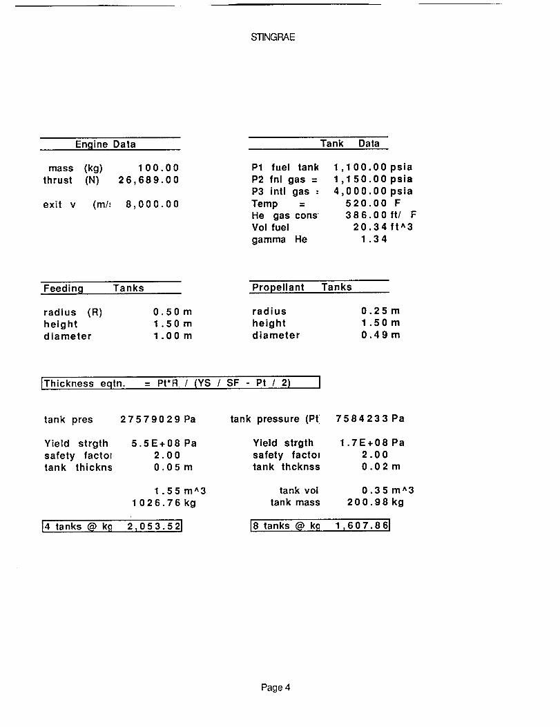
The calculation for the sizing of the propellant tank and the
feeding system appear on the following page. The tanks are
cylindrical in shape and have a diameter and height as shown. The
external volume and number of each tank appear boxed at the bottom
of the page. The helium tanks are made out of aluminium while the
propellant tanks are constructed of an internal tank of titanium and
an external tank of aluminium. The propellant tanks were design to
save weight over an all titanium tank and to protect against
Page 50
STINGRAE
Engine Data
mass (kg) 100.00thrust (N) 26,689.00
exit v (m/= 8,000.00
Tank Data
P1 fuel tank 1,100P2 fnl gas = 1,150P3 intl gas - 4,000
Temp = 520He gas cons' 386Vol fuel 20
gamma He 1
00 psia00 psia00 psia00 F00 ft/ F34 ft^334
Feeding Tanks Propellant Tanks
radius (R) 0.50m radius 0.25 mheight 1.50 m height 1.50 mdiameter 1.00 m diameter 0.49m
IThickness eqtn. = Pt*R / (YS / SF - Pt / 2)
tank pres 27579029 Pa
Yield strgth 5.5E+08 Pasafety factm 2.00tank thickns O.05m
1 .55 m^3
1026.76 kg
14 tanks @ kg 2,053.521
tank pressure (Pt 758423 3 Pa
Yield strgth 1.7E+08 Pa
safety factol 2.00tank thcknss 0.02 m
tank vol 0.35 m^3
tank mass 200.98 kg
18 tanks @ k_ 17607.86J
Page 4
Page 51
corrosion of an all aluminum tank. While the actual layout of the
system, tanks and engine, appears in the section on component
layout, a diagram of the entire system appears under the title of
Propulsion System. The system employs single point failure
protections and uses multiple storage tanks to insure against
contamination. A fuel mass of 1.05 percent is also used to insure
enough fuel is present. The pipes connecting the tanks are assume
to display Hagen-Poiseulle flow and this is accounted for through
pressurizing propellant tanks to 1100 psi instead of 1000 psi.
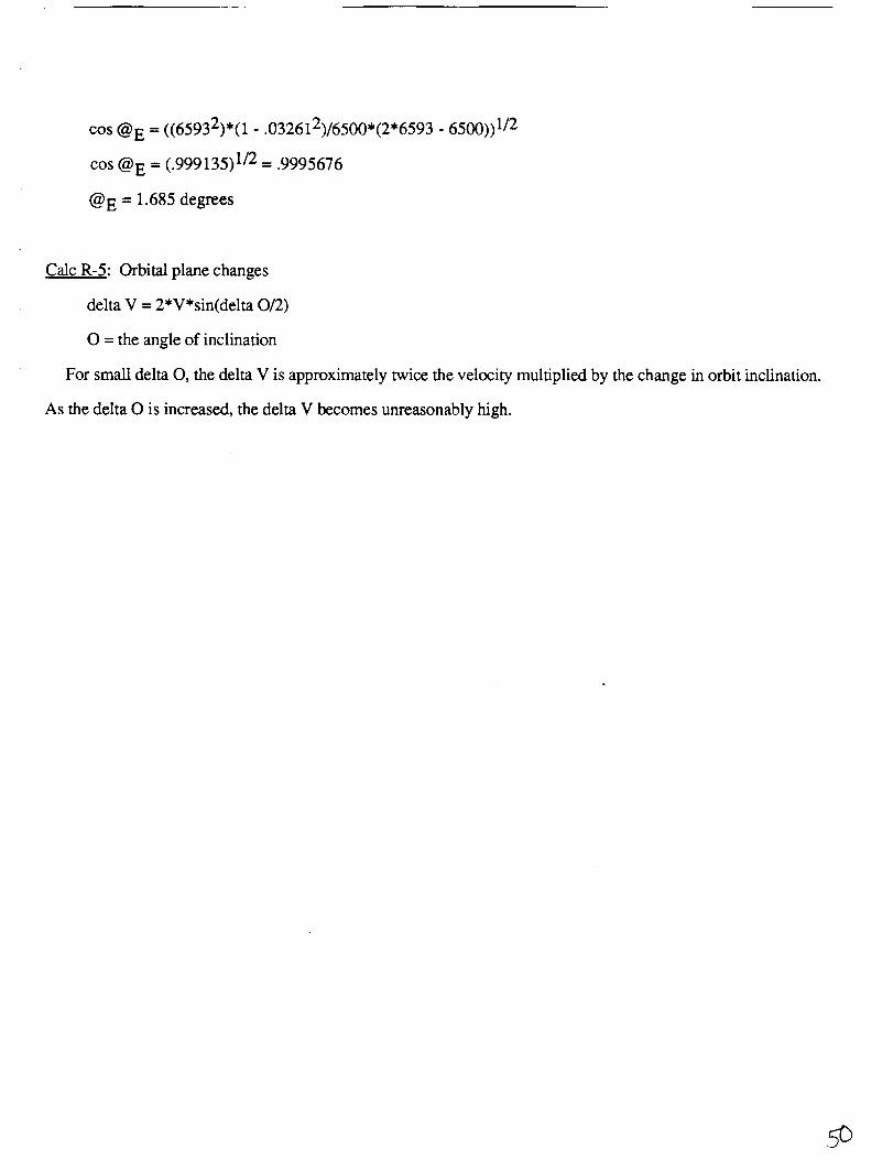
No delta V calculation are shown for platform maneuvers since
STINGRAE will not be going to the platforms. The following page
contains calculation as to how much fuel would be required for
STINGRAE to complete a mission to the polar platform. The velocity
changes necessary and their accompanying mass requirements make
this requirement infeasible. N.A.S.A. already has plans for an
orbital transfer vehicle, OTV, to assist the space station. It is
therefore STINGRAE policy that all platforms be brought to Freedom
by the OTV's and resuppied by space station personnel independent
of STINGRAE, i.e. space walk or mechanical arm.
As mention above, the engine of STINGRAE is a scaled down
version of a shuttle's orbital maneuvering system. The scale down
is in reference to the amount of times the engine is designed to fire
(500 min.). STINGRAE's engine will fire one order of magnitude less
as many times. The scale down of this aspect of the shuttle engine
Page 52
STINGRAE
ORBIT CALCULATIONSU
angle differencea
altitude
398600.001.21
6,668.146,688.146,708.14
V of space station orbit 7.73 km/sec
orbit change to polar platform from space station
Equation delta V = 2*V sin (0/2)
8.81 km/sec needed to obtain same plane
as polar platform
Now an altitude change is needed
Vneed (u*(2/r1-1/a))^.5
7.74 km/sec
delta V -- Vneeded - Vhave
delta V = 0.01 km/sec
Vneed = (u*(2/r2-1/a))^.5
= 7.70 km/sec
V2 need = (u/a)^.5
7,71 km/sec
delta V2 = 0.01 km/sec
ITotal delta V 0.02 km/sec I
Therefore the total delta V
needed for entire trip (toand from) is double the sumof the total delta V's
Using the rocket equation
an Isp of 400 (O & H)and a LRM mass of 6000kg
mass
1 7.67 km/sec
- 248792.00 kg
Page 3
Page 53
PROPULSION SYSTEM
valve
Oxidizertank
Check Checkvalve valve
_._ _/_Ta nkventvalve
__ _ High pressure
-- I gas valve
_ (remote control)
_--_I tank
Drainvalve
Gas bleedDrain
Gas filtervalve
Propellant valves(remote control)
_Restrictingorifice
Rocket thrust chamber
Page 54
is hoped to drive down STINGRAE's engine cost. In all other aspects,
the two engine should be the same.
The feeding system will use pressurized gas, helium, to displace
the propellants. This type of system has been extensively used in
space and is a simple and reliable means of throttling an engine. A
gas feed system also eliminates chugging of fuel. A feeding system
is paired with each propellant tank and several feeding lines and
valves are incorporated to insure redundancy.
The fuel will be mixed at a 1.65 ratio (same as shuttle's engine).
It has been widely used in space and can be stored for long
durations in such tanks as described above.
monomethylhydrazine possess a high Isp
therefore requiring no starting mechanism.
Nitrogen tetroxide and
and are hypergolic,
The second propulsion subsystem uses force cold nitrogen. This
subsystem is used to maneuver STINGRAE in the "dead" zone around
Freedom. The system also doubles as a attitude and articulation
system and further details of the system can be found under the
same heading.
Referenoes
Sutton George, Rocket Propulsion Elements,
Interscience.
Lembec Mike, AAE 241 Course Notes, 1989 Kinko's
1986 Wiley-
Page 55
Deidre Caldwell IrOUp #3
CS-
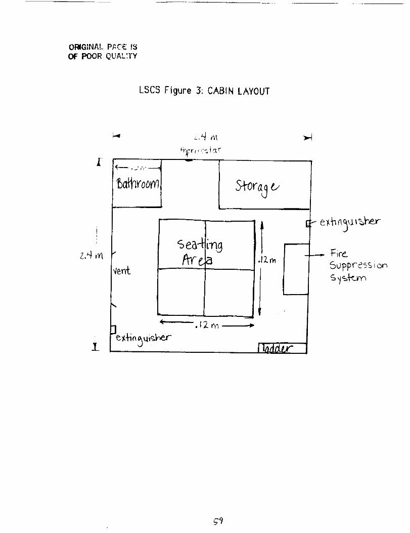
Life Suo0ort and Crew Systems
The purpose of the life support and crew systems (LSCS) is
to provide the necessary essentials for a crew's survival and
comfort in a manned spacecraft vehicle. Designing for the crew's
requirements is relatively complex in terms of the biological and
engineering aspects that have to be taken into account in order to
maintain an efficient as well as comfortable life support system.
The design requirements can be broken into three main divisions of
control and management: (1) environmental, (2) water and (3) waste.
The environmental control entails many requirements. A
shirt-sleeve environment is needed for the crew members for
comfort. With the design of an efficient LSCS, there should be no
need for a continuous use of a space suit. However, space suits will
be provided in case of an emergency. The need for supplies of the
atmosphere such as nitrogen and oxygen must be in abundance for at
least 24 hours use in space in conjunction with the other
consumables (lithium hydroxide, food, and water). There should also
include a cooling system for the metabolic and avionics heat loads
that are generated within an enclosed system. Fire detection and
suppression are important for human safety considerations. The
lithium hydroxide system will provide removal of carbon dioxide
and contaminants from the cabin's atmosphere.
Another system, water control and management, entails
providing water for drinking and sanitation purposes by storing the
water in the cryogenic tanks. In addition, the disposing of the
waste water (from water vapor) has to be taken care of in the space
vehicle.
Thirdly, waste control and management disposes of all the
wastes that has accumulated on the vehicle. The wastes includes
human solid and liquid wastes, uneaten food and expendable solid
wastes such as wet wipes, plastic gloves and liner bags. These
wastes are placed in a container and later removed after the
mission has completed.
Along with the above mentioned requirements, other factors
have to be considered to perform the project objective of STINGRAE.
Page 56
These factors are: (1) storage of foods, (2) medical supply and (3)
living space provisions. In regard to LSCS, one concern is to safelyreturn the crew members back to earth from the space station in an
emergency event. Thus, the following factors have to be taken into
account: (1) reasons for leaving the space station, (2) fail safe
redundancy and (3) equilibrium with the space station environment.To design the life support and crew systems, one vital
aspect is the duration and the number of passengers participating inthe mission. In order to determine an appropriate length and number
of men, trade studies and engineering analysis were made with
mission planning. The results for project STINGRAE are:
1. Number of Crew/Passengers
2. Mission Length/Duration
6 men
24 hours (1 day).
This duration is not the time of the return to earth from the space
station. It is the time allotted for providing consumables for the
crew members in case of trouble occurring when returning to the
planet earth.With such a short mission duration, it would not be practical
to consider a regenerative system for LSCS. The crew will be aboard
the vehicle only in emergency situations; otherwise, the vehicl.e willbe used as a logistics resupply transporter for the space station.
Taking this into consideration, there will be no reasons for intricate
designs for a kitchen galley, sleeping stations or urinal water-
flushing systems like that of the Space Shuttle Orbiter.
System Description
Environmental Control System
The single-gas system such as oxygen would be more easier
to control than a dual-gas system. However, the major disadvantage
of a single-gas system is that pure oxygen is a fire hazard. Thus,
STINGRAE is pressurized with 21% oxygen and 79% nitrogen designed
to operate at 101.325 kN/m^2. The cabin pressure is maintained by
means of a regulator. In case of an emergency, the regulator can be
Page 57
turned off and another regulator will support the cabin at 55 kN/m^2
similarly to the Space Shuttle Orbiter.
The pressurization system consist of one oxygen tank and
nitrogen tank system. For each of the consumables (oxygen,
nitrogen, lithium hydroxide and water), cryogenic tanks are used forstorage because they are condensed, light weight, and thin-walled.
Figure A.1 is a listing of how the volume sizing of the tanks where
calculated. A trade study (Figure A.2a) was done with three metals
that would be acceptable to store the consumables: steel, aluminium
and titanium. Figure A.2.b is a table of the density, yield strength
and mass values of the three materials. The aerospace material
used is aluminium 2024-T4. This metal has low density of .1000
Ib/in*3 which constitutes a lightweight mass for the storage tanks.
Aluminium was an appropriate choice due to the considerable weight
savings which in turn reflects a cost reduction compared to theother materials.
The oxygen tanks are pressurized at 20678.6 kN/m*2 by
controlled heaters and released into the cabin area in a gaseous form
to the oxygen supply valve. This gaseous oxygen flows through a
cabin heat exchanger where the gas is warmed before passing
through the regulators. Two tanks, where one is used for
emergencies (50% reserve), are provided,
The nitrogen system has two storage tanks (one for reserve)
at 20678.6 kN/m^2 (Figure A.3b). Similar to the Space Shuttle
Orbiter, the nitrogen valve controls the pressure of the nitrogen gas
to 1378.6 kN/m^2 when it arrives at the regulator. Then, the
nitrogen is joined with the oxygen by a control valve. The
nitrogen/oxygen pressurization system will provide airflow into the
cabin by means of vents and inlets. If the inside air pressure islower than the outside' pressure by 1.4 kN/m^2, the vent valves will
be opened to permit air to flow into the cabin. In addition, thesevalves can be made to emit air from the cabin when the cabin
pressure exceeds 107 kN/m*2.
The air circulation is provided by a cabin fan (an additional
one is used for emergencies). It operates much like the Space
Shuttle Orbiter by propelling air from the cabin to the lithium
Page 58
Fioure A. I
This is a listing of the equations used in calculating the total mass,
height and diameter of each type of cryogenic tank.
Unit conversion 1 1 ft^2 = 144 in^2
Unit conversion 2 .02832 m^3 = 1 ft^3
Unit conversion 3 6892,857 N-in^2 = 1 Ibf-m^2
Unit conversion 4 0.4535 kg = 1 Ib
gas constant : R [ft-lbf/Ibm-°R]
oxygen: R= 48.28
nitrogen: R= 55.15
m= molecular weight
Ro- universal gas constant
R- specific gas constant= Ro,'m
water: R= 85.772
m= 18.016 g/molRo= 8.3144 Joules/°K-mole
R= (8.3144 Jl=K-mol)(mole118.016g)(.737652ft-lbf/J)
(1 g/.0022046 Ibm)(1 K/1.8 °R)LiOH: R= 64.52
m= 23.95 g/tool
temperature : T= 540 °R
pi constant : x= 3.14159
density : p [lbs/m^3]
mass : m [kg]
tank pressure : P [Nlm^2]
inner volume :Vi [m^3]
Vi = mRT/P
m [Ibm],R [ft-lbf/Ibm-°R],T [°R],P [Ibf/in^2]and using unit
conversionI & 2.
inner radius : riIra]
ri = q(Vi/xhi)
hi [m] = assign an arbitrary value; by changing the value of hi,
the mass of the tank can be adjusted to reach a desired mass,
yield strength : Sy [N/m^2]
Factor safety : FsFs= 2
stress : s IN/m^2]
s = Sy/Fs
tank thickness : t[m]
t = Pri/(s-P/2)
outer height: h [m]
h=hi+2t
outer radius : ro [m]
ro = t + ri
outer diameter : do [m]
do = 2(ro)
outer volume : V Ira^3]
V = _(ro)^2h - _(ri)^3
tank mass : ml [m]
ml = pV
mass total : mt [m]mt = m + ml
Page 59
Iooo Trade study [Figure A.2i]
800 '
600
20O
Th,i 4 I _ _ _1 lJl_$,_, y'l_ I1rlnQ_. I_ mill VOIVII
OI SlI4_ |_Jnum. I/_ tlJ_Jm ThlSl I_ors we4e _@lefm_ _y
_e same _.444 d;s_zFe_ • F_ure AI. FrOm U%_ dall. 8 trJ_e
$1_y was con_,led _ deletm,_4 _he most _es*rable malelrlal lype
,n _e_ml _ '_,e_ht Oc,ns_enlllgnl T_ SubslanCe $1oted was wa_e_
al a _Bssu_ o_ 20678571 _m'2 and _em_e_aluto ol 540 *R
&dd,l_o hal conslra,nls:
m. 6_WQ
h. 2m
R - 95 772 (waS*r} _._t_n-'R
Matew%mlType
U&lef_aJ lyl:_ _e_s,_ ylek_ S1_englh mass
Steel
_Si 1025 17329 91 36 1092 595
5CrMo-V 17145 79 200 804 9046
Aluminum
2024-T4 4101 8_ 40 375 493
5086-H32 5857 63 25 4140367
T_lanium 988475 110 4_2.14
Page 60
C Figure A.3b I
This is the mass and dimensional factors for the nitrogen tanks.
Sample calculations 'are provided, .¢i "" ....
J fJ
Nitrogen
LeakageTank #G
T.251 m
NitrogenTank #H
mass (nitrogen)=3.59 kg
mass (tank + nitrogen)=
89.43 kg
mass (nitrogen)= 21.29 kg
mass (tank + nitrogen)=
176.45 kg
.628 m
NitrogenTank # I
T.288 m
mass (nitrogen)= 10.64 kg
mass (tank + nitrogen)-,
176.11 kg
Material type: Aluminum (cryogenic)Consumable type: Nitrogen (leakage)Tank ID: #G
Unit conversion 1 144Unit conversion 2 0.02832Unit conversion 3 6892.857Unlt conversion 4 0.4535gas conslanl 55.15temperature 540pl constant 3.1415gdensity 0. Idensity 6101.696mass 7.92mass 3.59172tank pressure 3000tank pressure 20678571
InA2/ft^2mA3/ftA3N.InA2/Ibf.m^2
k-_llb .._.fl-lbf/Ibm-OR°R
lbs/InA3Ibs/mA3IbmkgpalN/m^2
Yield strength 4 0kslYield strength 275714.3Nlm^2Safety Factor 2stress 1.38E,00 NImA2tank thickness 0.025439mouter radius 0.182311 m
• outer height 0.250878m• outer diameter 0.364623m
outer volume 0.014068mA3• tank mass 85.83991 kg
total mass 89.43163kg
Inner volume 0.015462 mInner height 0.2mInner radius 0.1 56873m
Page 61
hydroxide canisters. These canisters have to replaced on a daily
basis. The main function of the canisters is to remove non-metallic
materials, stored gas leakage, metabolic processes from the crew,
odors and contaminants. The canisters contain a layer of activated
charcoal, glass wool filter, and lithium hydroxide. The activated
charcoal absorbs the odors and noxious gases. It absorbs organic
materials such as alcohols and hydrocarbons. A glass wool
filtration minimizes the aerosol hazards such as Freon 1301(fire
extinguisher chemical). It will also trap the solid particles and
lithium hydroxide from entering the cabin's atmosphere. The carbon
dioxide is removed by means of the lithium hydroxide. This
substance is highly reliable and readily absorbs carbon dioxide in the
presence of water vapor in the gas stream. The exothermic chemical
reaction in Figure A._4 illustrates this principle. If the carbon
dioxide is not removed, the crew will suffocate. Thus, the present
design levels for the carbon dioxide partial pressure is 0-8.0 mmHg
for normal design limits and 0.3 mmHg as an optimum value.
The cabin temperature is maintained at 70 ° - 75 ° F by use of
manual temperature controllers. To regulate the humidity, the air
flow pulled over the coldplates (heat sinks or special metal plates
that contains channels through which water and mixtures flow)
from the cabin heat exchanger. Condensation occurs when the
temperature changes as the air flow passed over the coldplates. A
centrifugal water separator, fans and the cabin heat exchanger
divides the water from'the air. The air is recirculated back into theP
cabin; whereas, the water is vented overboard. An air circulation
system for the orbiter removes 1.8 kg/hr of water.
Besides circulating the desired temperature and air mixture,
the air circulation system also collects the heat from the crew and
crew avionics. Warmed cabin air is passed through the cabin heat
exchanger and the excess heat is directed to the water coolant loop.
For STINGRAE, the amount of heat released from various system can
be viewed in Figure A.5.
The water coolant loops have pumps that pass the water and
heat through a Freon interchanger and then to the radiator. Because
of the high latent he_'t of vaporization and the absence of pressure,
Page 62
water can boil at low temperatures. The radiator and the flash
evaporators will boil the water at low temperatures and pressures.
Then, the outcoming steam vapor is vented out to space by means of
a cabin pressure relief valve.Fire is detected by means of smoke detectors, which are
distributed throughout the space vehicle. The smoke detectors will
alarm when any type Of increase of gas or combustion occurs. The
fire extinguishers will be used for suppression of the fire.Bromotrifluromethane or Freon 1301 is used for chemical fires
because instead of smothering the fire, it breaks down the chemical
reaction of the fire. Figure A.8 has a listing of the number of
extinguishers used in LSCS.Figure A.7 is a schematic diagram of the environmental LSCS
system loop. Figure A.8 is a listing of the component's dimensions
and power values.
Water Control and Management.System
The water system is one of the most critical life support
requirements. Because of the duration of STINGRAE, a pressuret
control regulator will monitor the water flow from the cryogenic
water tanks to a water control valve. Even though the Space Shuttle
Orbiter provided water from the by-products of the fuel cells, it
would not be advantageous for STINGRAE in terms of extra weight of
pumps and valve. A microbial check valve and filtration system is
located in the supply line between the cryogenic tank and the water
dispenser. The dispenser will be used to allow the crew member to
gather the amount needed for drinking. Once the water tank is
empty, a water meter will signal the attachment of another water
tank. This will be done manually by a crew member. The water's
temperature will be the same as when it was stored inside the
cryogenic tank. There. will no devices for adjusting the temperature
of the water.
The collection of waste water that has been drawn from the
atmosphere is vented overboard in the form of steam by use of the
radiator and flash evaporator.
Page 63
cold _lates Fan
watercoolant
loop
\valve
!'.',_1
airflow
LiOH Canister
water
i
water
Thermal
Capacitor
Cabin
/
I Pressurecontrol system
C__ Iheater]
Wa_ner
overboard
Page 64
Fioure A.8
Listed below is the mass and dimensional factors for the
components in LSCS. Because of insufficient, data, all themeasurements could not be located. Most of the data was gatheredfrom the ECLSS of the space shuttle. The shuttle is quite larger thanour vehicle. However, most of the area is used for storage and themid deck area is very spacious. On the other hand, our vehicle's goalis to decrease the mass and volume specifications. Taking this intoconsideration and the fact that the number of men on the orbiter issimilar to our vehicle, the dimensions and power constraints of theorbiter was reduced by a factor of 1/2 in order to get themeasurements for the STINGRAE vehicle.
System Number Mess Height Width Length
(diam.)lkal (ml (m'l Ira1
Tank A 1 599.2 .435 .899Tank B 1 390.9 .398 .635Tank C 1 146.5 .358 .344Tank D 1 78.38 .344 .243Tank E 1 166.7 .283 .595Tank F 1 109.7 .259 .420Tanl¢ G 1 89.43 .251 .365Tank H 1 176.45 .324 .888Tank I 1 176.11 .288 .628
Freon 1301 4 6.35Fire Exting. 4 34.36 .8128 .2286
Notei The height, length and width are the same.
System Mass Length(kal (ml _
Cabin Heat Exchanger 9.96Coldplate Waterloop 46.67Cabin "Temp. Controller 2.22
Heaters(2) .1134Flow sensors(2) 374Pressure sensors(12) 1.02Carbon dioxide
sensors 1.21
Water Bypasscontroller 2.23
Main Cabin Fan 2.04Fan Downstream
Valve .102
Venting FanBypass valve 1.15Waterloop Pump 7.24Water bypass valve(3) 1.93Flash evaporator
system 13.13Thermal Capacitor 45.36Food and Containers' 5.44FES Duct HeatersFire SuppresionO2/N2 Supply PanelO2/N2 Control Panel
1.35.1074.1723
1.20.44.0801
.0108
1.148.1367
.0775
.261261.142
.352384.291
Powert'Wattsl
8
6.67
0.5
0.1
4.090
8.5398.54.35
4
12.511.52.25225.12
• Note: Food Calculation
food consumption: 1.5 Ib/man-day(6 men)(1 day) - 4.08 kgexpendable containers: 0.5 Ib/man-day(6 men)(1 day) - 1.36 kOTotal - 5.44 kgdensity of food as packed for storage - .008 Ib/in^3volume= .0245 m*3; length..291 m
Page 65
Waste Management and Control System=i
This system collects human wastes in addition to wastes
from food and other paper-like material. Within the area designated
as B-Room (Figure A.6), a crew member can release his wastes
(feces and .urine) into a plastic, durable, water-proof bag located in
the center of the commode assembly. Restraints for the feet and
waist and a handholds are situated for the passengers positioning
and stabilization when using the B-Room. The toilet tissue, waste
and germicide are sealed in the plastic pouch and then stored in a
trash container. The germicide kills the microorganisms that causes
the decay and odor. In addition, a vent will be located in the B-
Room for the removal of odors and gases. The tissue is a multi-ply,
absorbent and Iow-lintiag paper material. The crew member should
then clean the seat of'the commode with a biocidal cleanser and a
general purpose wet wipe while disposable plastic gloves are worn.
These items are placed in a plastic bag and stored in the trash
container. A newly bag liner should then be placed in commode seat
assembly. Wet wipes (personal hygiene miniature towels that
contain quaternary compound ammonium), uneaten food and
miscellaneous trash are disposed in a plastic, water-proof bag in
the trash container. A privacy curtain of Nomex cloth is attached to
the walls which isolates the B-Room from the rest of the cabin area.
The trash container has a liner and must be fastened. It is
located in a separate storage area and it includes a ventilation
system.'l
Food Management System
The quality and quantity of food consumed by the crew
members of the space vehicle should approximate closely to a
normal diet as on earth. The food will be freeze-dehydrated and
bite-sized compressed. Since water is removed from the food by
this process without damaging or changing the chemistry, about
70% of the bulk weight can be reduced. The food will be consumed
directly from the package. The packages are made of laminated
plastic bags that are over-wrapped in a non-flammable
flurohydrocarbon. No oven or refrigerators will be needed in order to
Page 66
reduce weight. However, utensils, mainly plastic spoons, will be
provided so that a crew member can eat right out of the plastic
pouch.
Medicine Supply
Because many possible crew illnesses and injuries will
occur on the space station, STINGRAE must be able to accommodate
for such situation. However, X-ray machines and clinicallaboratories are not feasible in terms of volumetric considerations
for STINGRAE. Only the basic medical equipment should be placed on
the spacecraft. Figure C.1 details a typical kit supplied to Geminiastronauts. For STINGRAE, these kits will provided for each crew
member in addition to extra bandages, cold packs and splints.
Living Space Requirements
Establishing an appropriate volumetric standard is vital in
order to consider the amount of living space available for the crew.
A minimum (lower limit) of 1.42 m^3/person is adequate for 1 or 2
days of confinement where no impairment or marked impairmentoccurred during this brief confinement. The other limits can be
calculated by the following tolerance volume requirements
equations:
V(min) = -(0.0040)x^2 + (1.4219)x + 81.307
V(acc) = -(0.0068)x^2 + (2.8346)x + 83.440
where x is the known mission duration measured in days
and the resultant volume is measured in ft^3/man-day.To convert the resultant volume to cubic meters, multiply
by the number of men, the number of days, and .02832.
For project STINGRAE, the calculations are:
Lower limit: V = 8.52 m^3,
Upper limit: V(min) = 14.05 m^3, and
V(acc) = 14.66 m^3.
Page 67
( Figure A.6
{, I\ I
Food Storage Area
\
scellaneou(. Water
Dispenser
\
Medical
Equipment
Reference: Sharpe, Mitchell, R., Living in Space,
Doubleday Science Series
This figure i#ustrates a typical emergency medical kitsupplied to crew members.
Drug Dose and Use AmountForm
Cyclizine hydtochloride 50 rag. tablets motion sickness 8
Dextro- amphetamine sulfate 5 rag. tablets stimulant 8
APC (aspirin, phenacetin, & tablets pain 16caffeine)
Meperidine hydrochloride 100 rag. tablets pain 4
Tdprolidine hydrochloride 2'5 rag, tablets decongeslant 16
Pseudoephedrine hydrochlotide 60 rag, tablets
Diphenoxylate hydrochlodde 2"5 rag, tablets diarrhe== 16
Atropine sulfate 0,25 rag. tablets
Tetracycline hydrochloride 250 rag. tablets antibiotic 16
Methylce(lulose solution 15 co. in bottle eyedrops 1
Parenteral cyclizine hydro- 45 rag. (0.9cc, motion sickness 2
chloride in injector)
Parenteral mepesdine hydro- 90 mg. (0.9 co. pain 2
chloride in injector)
Page 68
Threats
There are many reasons for crew members to evacuate the
space station. For instance, if a fire were developed on the space
station and could not be suppressed, the crew members would need
an emergency vehicle to transport them to safety. Below is a
listing of the possible threats and their causes:
1. Fire
2. Biological (toxic) contamination
a. experiment
b. fire
c. fuel leak
3. Injury/Illness
4. Explosion/implosion
a. leakage
b. ruptures/structural failure
c. relief valve fails to close
d. fire/overtemperature
e. chemical reaction
5. Loss of pressurization
a. puncture
b. inadvertent crew action
c. internal/external leakage
d. remove contamination
e. fire control
f. maintenance
6. Meteoroid and debris penetration
a. tracking of 1-4 cm of meteorites and debris
7. Tumbling/Ios's of control
a. pressure _essel penetration
b. thruster stuck on or off
c. collision
d. CMG failure
e. power failure
8. Out of control EVA astronaut
a. fire
b. illness/injury
Page 69
c. impact
d. explosione. penetration
f. depressurization
g. consumables depletion
9. Consumables depletion
a. leakageb. contamination
c. LRV failure
d. launch vehicle failure
10. Orbit decaya. thruster failure
b. no fuel
With these possible threats in mind, the STINGRAE should be
able to separate from the space station rapidly, availability of
pressure suits, ease of entry to the earth's atmosphere, recycling of
air, Iow-g reentry, close landing to medical facilities and the
ability to track an EVA astronauts. The other subsystems will be
able to provide these requirements for a safe and comfortable
landing to earth. In addition, injuries, illness and uncontrollable
EVA astronauts are the only causes for a partial evacuation. Theother causes will lead ;to a total evacuation. The evacuation options
that STINGRAE will be able to explore are: (1) return to earth or (2)orbit until the space station is habitable.
Other requirements
Fail safe redundancy is an important factor because it
ensures that nothing will go wrong if there are backup systems or
continous monitoring of the various components of LSCS. If
everything is redundant and fail safe, then nothing should go wrong.The STINGRAE has sensors and meters to alert the crew if a
potential problem occurs with a valve, pump, or a ventilation
system. A basic tool kit will provided for the crew. In addition, a
Page 70
manual override is provided for each subsystem in case a system is
not working properly.
When the STINGRAE is docked to the space station, it must
have similar systems so that the vehicle can use the space station's
system. The only LSCS systems that will feed off of the spacestation is the environmental control and the power-generated
systems.
Conclusions
The life support and crew system can be designed by
utilizing many different combinations of design parameters.Foremost, the vehicle must provide safety for the crew. By
selecting optimum subsystems to meet all of the requirements is
no assurance that the LSCS will be an optimum system. Taking into
consideration that the mission is not for a long duration, the vehicle
need not to be a duplicate of a well-designed apartment. By
minimizing the cost constraints, the size and the weight of the
components in the LSCS have to be kept a minimum. Thus, only thenecessary essentials for survival are needed and implemented in the
STINGRAE LSCS design.
Page 71
8Jd.I.[. ZCd
Allen, David H., Introduction to Aerospace Structural Analysis, John
Wiley and Sons, 1985.
Angelo, Joseph A., The Dictionary_ of S0ace Technotoav, Van Nostrand
Reinhold Company, 1983.
Baker, Robert, Space Exploration. McGraw-Hill, Inc., 1964.
Belew, Leland F., Skylab: A Guidebook. National Aeronautics and
Space Administration, Washington, D.C., 1973.
Chambers, Alan, Second Confere.nce of Portable Life Support
Systems, NASA SP-302, National Aeronautics and Space
Administration, Washington, D.C., 1972.
Conference on Nutrition in Spa_;0 and Related Waste Problems. NASA
SP-70, National Aeronautics and Space Administration, 1964.
Enoineerin9 and Configurations of Space Stations and Platforms,
Noyes Publications, 1985.
Issacs, Theodore, Project Nero; Near-Earth Rescue and Operation. The
M.I.T. Press, 1967.
Kammermeyer, Karl, Atmosphere in Space Cabins and Closed
Environmeqt_, Meredith Publishing Company, 1966.
Purser, Paul E., Manned S0ace_:raff; Engineering Design and Operation,
Fairchild Publications, Inc., 1964.
Sauer, Richard, Food Service and Nutrition for the Space Station,
NASA CP 2370, National Aeronautics and Space Administration,
Washington, D.C., 1985.
Sharpe, Mitchell R., IJvin0 in SoacQ, Doubleday and Company, Inc.,1969.
Space Shuttle- Sky!ab. Committee on Science and Astronautics,Washington, D.C., 1972_
Tipler, Paul A., Physics, Worth Publishers, Inc,, 1982.
Ward, Timothy J., HabitabiliW Considerations for a SDace OPerations
.C..O_E[._, University of Illinois at Urbana-Champaign, 1983.
Page 72
ED HEINEN
MISSION MANAGEMENT,
REQUIREMENTS:
PLANNING AND COSTING
Identify Payloads
Integrate Payloads into transport module
Launch vehicle selection
Trajectory options
Mission Support
After receiving the requirements set forth in the request for
proposal, they were organized according to importance. For mission
planning purposes the two most important requirements were the
establishment of payloads that would ride aboard the vehicle, and the
selection of an expendable launch vehicle to lift both vehicle and
payload. Because of their importance these two topics were dealt with
first. Establishment of payloads was the first task to be attacked
since a payload weight and volume were needed to obtain an idea of
which launch vehicle could be used.
PAYLOAD IDENTIFICATION
Since the need of the space station for periodic resupply was the
impetus behind the formation of our program, it is natural to ask what
types of supplies are necessary for the station. Needs of the station
were divided into the following categories: crew, station, and
customer support. Crew support entails the replenishment of food,
hygienic materials, medical supplies, and clothing. Station support
involves provisions necessary for housekeeping, waste management,
Page 73
trash, spares, ECLSS fluids, and EVA support.
customers must be considered due to the
modules which are supplied by the customer.
Finally, support for the
needs of the individual
Needs of the customer
fall into the categories of servicing plant, animal, and human research
along with various other scientific experiments. Once the areas in
which these supplies were going to be used was determined, it was
then necessary to determine quantity and form of the supplies.
Quantities and forms obtained by using data compiled from the NASA
Annual Resupply Mass Summary and the OSSA Missions Waste Inventory
Database were then tabulated to give the ninety requirements for
up/down mass and up/down volume. These lists further itemized the
resupply requirements in terms of pressurized, unpressurized fluids,
and propellants which was an important consideration for the
structures person when deciding to pressurize the vehicle. Finally
these areas were broken down even further into crew-station and
customer categories. The results are as follows:
MASS FOR RESUPPLY MISSIONS
CLASSIFICATION
Pressurized
crew/sta.
customer
Unpressurizedcrew/sta.
customer
Fluids
crew/sta.
customer
MASS UP(kg)
4148.56
4954.14
513.01
4152.18
360.61
365.14
MASS DOWN(kg)
3497.99
4757.39
513.01
4152.18
0.00
173.73
Page 74
Propellants
crew/sta. 45.36 0.00
customer 0.00 0.00
TOTAL 16220.92 13094.30
VOLUME FOR RESUPPLY MISSIONS
CLASSIFICATION VOLUME UP (m3) VOLUME DOWN(m 3)
Pressurized
crew/sta. 14.78 11.50
customer 13.92 13.75
Unpressurized
crew/sta. 4.53 4.53
customer 32.64 32.64
Fluids
crew/sta. 0.45 0.00
customer 0.50 0.00
Propellants
crew/sta. .57 0.00
customer 1.68 0.00
TOTAL 69.06 62.59
Two types of resupply are possible for these missions. The first
type of servicing is pranned servicing where certain supplies are
brought up in a routine manner or schedule. This involve the
replacement of consumables, refurbishment, replacement of degraded
systems at known times and the scheduled replacement of old systems
with new ones. The other form of resupply is of the contingency type
where resupply is non-routine or non-scheduled. This means that
Page 75
spares must be carried onboard the vehicle in order to be prepared for
random failures.
LAUNCH VEHICLE SELECTION
After establishing the masses and volumes to be lifted into orbit,
attention was turned toward selecting a launch vehicle. The main
launch vehicle requirement was that it had to be expendable. Using the
expendable launch vehicle information supplied in class (name of
source),various pieces of information were selected to represent the
best characteristics of each lifting the vehicle. The criteria used for
the final evaluation were: orbit and lifting capability, launch site,
payload fairing size, and Delta V needed to attain various orbits. The
next step in the process was to estimate the mass of the resupply
vehicle.
An initial craft mass estimate was needed to determine an initial
system weight so that ELV's with lighter lifting capabilities could be
ruled out. Using a structural efficiency of .2(a good estimate for a
small rocket) an initial estimate of 4055 kilograms was obtained for
the vehicle. The procedures used to obtain this value were as follows:
Ms/Mi=.2 where Mi=Ms+Mp+Mf
Mf -- Mass of fuel
Ms = Mass of structure
Mp = Mass of payload
Ms = .2Mi = .2(Ms + Mp + Mr_)
Ms = .25Mp
Page 76
Since the fuel mass was eliminated, the resulting calculation
estimates a total system mass which is lighter than the actual mass.
Initially the payload mass was assumed to be equal to the full ninety
day requirements in order to evaluate the possibility of a single launch
fulfilling the mission requirements. However, these calculations yield
system mass of 20276 kilograms without fuel. This figure cut the
possible ELV's down to a Titan IV rocket using solid rocket motor
upgrades(SRMU's). This version has the capability to lift 22,220
kilograms, but once fuel and tank mass were taken into consideration it
was also ruled out. Therefore, the possibility of lifting the total
ninety-day resupply needs in one launch was ruled out.
After learning this fact, the next step was the comparison of
Delta V needed for the various space station orbits. Knowing the
amount of Delta V necessary for each orbit would also helped in the
development of a scheme for the allocation of mass and volume for the
various launch vehicles. Data on the space station states that its orbit
ranges anywhere from 290 km up to 430 km away from Earth. 1 With
this information a range of Delta V's needed to achieve various station
orbits were calculated based on Hohmann transfers from a 100 nautical
mile orbit. The 100 nautical mile(185.20 km) orbit was used because
nearly all of the possible choices for ELV's inject their cargos into this
orbit. An orbit of 220 nautical miles(404.44 km) was also considered
because a few ELV's which can attain this orbit. Maneuvering times
from this orbit to the station orbit were also calculated for later
reference in constructing the mission timeline. The resulting figures
are as follows:
Page 77
D_I+_ v to station orbits from an initial orbit of 185.20 (km)
160
¢=
¢DQ
140
120
1O0
8O
60200 500300 400
Station Radlus(km)
Time to obtain station orbit from 185.2 km
160
140
"_" 120
EI--
100
8O
60
200 300 400
Station Radius (km)
50O
Below are the equations used for
/_,( Z
the calculations:
÷V (IR,
Page 78
After receiving mass estimates for the various subsystems, the
final percentages of the ninety-day resupply requirements to be
launched each mission was determined along with the exact launch
vehicle. Based on the Delta V's, cost per launch, ground support costs,
and lifting capabilities the Titan IV with SRMU's which lifts roughly
22220 kg into orbit was selected. After obtaining a final vehicle
weight of approximately 11000 kg, it was determined that the best
percentage of the 90-day resupply requirements to be lifted each time
was 50 percent.
Once the vehicle and payload sizes were determined,
concentration was turned toward fulfillment of the crew emergency
return requirement. The possible crew sizes were set at a minimum of
two and a maximum of eight. The minimum crew size comes from the
requirement that one person must always accompany an injured or ill
person back to Earth. Because the space station will have at most eight
people on board at a time, the crew return system need only
accommodate a maximum of eight people. This poses an interesting
dilemma. How many vehicles or how many people per vehicle is the
optimum solution? It was immediately seen that one vehicle at the
station with a capacity of eight is incapable of providing a feasible
solution for an illness situation. If one person were ill, not only would
another person have to accompany him but also the remainder of the
crew because there would not be any vehicles to return them to Earth in
case of another emergency. Likewise, a two vehicle system with each
vehicle having a capacity of four people does not work.
Page 79
The design of the optimum system is based on the double
emergency(DE) situation of a three vehicle system where an injury or
illness occurs requiring the return of a crewmember to Earth. After
the vehicle has already left the station another accident occurs and
crewmembers must be returned to Earth in the remaining vehicle. The
worst case scenario was used in which it was assumed that one of the
vehicles at the station does not work or cannot be reached. Based on
this scenario the six-person vehicle is the best choice. A two-person
vehicle and a three-person vehicle is ruled out because several vehicles
would be necessary to cover the DE situation and thus the total cost
would be enormous for launching all of the vehicles As shown earlier
the four-person vehicle will also not meet the DE situation
requirements.
The final choice between six- and eight-person vehicle was a lot
more difficult. Both can easily sustain the DE situation. However, if
two people go down in a six-person vehicle and a second emergency
occurs there will be exactly six people left to ride aboard the six
person vehicle; therefore maximizing the space available on that
vehicle. The eight-person vehicle on the other hand would be wasting
room for two extra people. If for some reason the crew cannot be
returned to Earth by the normal means of transportation, a six-person
STINGRAE has the maximum amount of waste carrying capability
available when fully loaded as can be seen by the following graph
depicting the acceptable volume for humans against time in the vehicle.
Page 80
8O
6O
Volume (m^3) 0
2o
0
Data from "vol. dat"
| |
0 1 2 3
Time (days)
------=---- 8-man
6-man
4-man
•-----e--- 3-man
2-man
Up Volume
Included in the graph is a line showing the volume resupply
requirements in order to show that the six-person vehicle possesses
the best payload capabilities at maximum crew capacities.
Overall system requirements mandate a minimum of four
vehicles, one of which must be used as a test vehicle while remaining
flight ready. The total number of vehicles at the station at any one
times is based on the DE situation. In the event of this situation
happening, two vehicles will be necessary to return the crew members
and a third will be available in case access to one vehicle is denied or
the vehicle is not working properly. On the ground the total number of
vehicles will be four. One will be used for continuous testing and spare
parts. The other three will be used in the ground-station rotation
system. Once the first three vehicles are positioned at the station,
the other three will be rotated in as they arrive at the station for their
Page 81
scheduled delivery. Each time a new vehicle arrives, it will replace the
vehicle which has been there the longest period of time. The returning
vehicle will then return to Earth for refurbishment and await
processing for the next mission.
PAYLOAD INTEGRATION
Once the crew size was selected, work on payload integration
began. The major factor involved in arranging the payloads is whether
or not they are pressurized or unpressurized. Obviously, the
unpressurized items are the first items to be loaded due to the fact
that they can be put into the vehicle before it is pressurized without
worry of damage. Items which fall into this category are: clothing,
cleaning supplies, and scientific experiments. In the same sense, some
of the pressurized cargo probably will not be able to survive extended
periods of time without pressurization. When live specimens are to be
carried aboard the vehicle care must be taken to keep the conditions in
the cargo hold at and acceptable so that they remain healthy. Medicine
is another item that must be loaded shortly before launch. The
astronauts cannot afford to become sick and then take medicine which
is bad and worsen the situation. All unnecessary trips back to Earth
are to be avoided since the major purpose of this vehicle is resupply.
Another consideration for payload integration is ease of loading
and unloading supplies. Since there are a number of double racks in the
space station, storage racks were developed similar to the double racks
in the space station. These racks have the capability of holding the
exact same drawers as used in the space station. The vehicle racks are
stocked such that all drawers that must go in the same rack on the
Page 82
station are also in the same storage rack on the vehicle, once again
allowing the payload to be more efficiently loaded and unloaded. Still
another way to increase loading and unloading efficiency is to set
standard sizes on the shapes of the containers which hold the cargo.
The drawers for the station double racks have already set a standard
size for many objects. In order to maximize the available volume,
containers which conform to the shape of cargo hold were selected.
These containers are used for the storage of clothing and nonperishable
items. Since many different sizes of payloads need to be carried, it is
not possible to require that all items be put into standardized
containers. The standardized containers will start in the rear of the
craft and work forward. Some items such as the racks holding the
drawers for the station will be on every mission so the loading is done
using them as a starting point. This means other standardized
containers will be stacked in and around the drawer racks. The further
organization of the remaining items will be based on the need to
balance the load around the center of mass. To do this, an inertia
resolving program is used to find the new moments of inertia and
center of mass for the vehicle based on the various loading schemes.
The final loaded configuration is determined a couple of months ahead
of time since the exact payload manifests are to be submitted several
months ahead of their predetermined launch time.
Finally, human cargo must also be accounted for due to the fact
that an emergency situation most likely means that they have to ride
aboard the vehicle back to Earth. There are two possible positions in
which the astronauts might have to return to Earth. One is in a sitting
Page 83
position, and the other is in a lying position. In order to satisfy both
needs the following chair in was designed: l_"_.4F_e--
This chair can be quickly and easily set up by inserting the necessary
support rods into their designated holes. In the event of an illness or
injury , the chairs will be placed in the reclined position and then
supported with the remaining support rods. These chairs will be sent
up on one of the three initial launches. Once the chairs have arrived at
the station they will be set up in each of the vehicles docked at that
time. As new vehicles arrive at the station, the chairs will be
dismantled for transfer to the new vehicle. The chairs will be returned
to the station on the next available mission.
MISSION OUTLINE
The overall mission scenario is as follows:*
1.) Liftoff from Cape Canaveral
2.) Arrival at lift vehicle orbit(185.20 km)
3.) Begin Hohmann transfer to station orbit
4.)Arrive at station
5.)Unload cargo and move chairs to the new vehicle
6.)STINGRAE with most time at station begins reentry
process
7.) STINGRAE lands at Cape Canaveral landing site**
8.)STINGRAE is returned to refurb, and proc. center
9.)STINGRAE begins payload integration
Page 84
_i _ -
!!Ii
!
!J
j,'
_,_ i¸
_ _ q
II
I
I
J
Page 85
10.)STINGRAE moved to launch pad to ready for launch
* The overall mission Delta V will vary depending on the station orbit
** In case STINGRAE is unable to land at Cape Canaveral its secondary
landing site is Vandenberg Air Force Base. In case neither one of these
landing sites is available, Reentry and Recovery has compiled a list of
alternative landing sites.
PROGRAM IMPLEMENTATION
Projections estimate that the availability of the Titan IV launch
vehicle with SRMU's to be 1994. However, design, development, and
testing of STINGRAE, will take in the neighborhood of five years. This
means that the first phase of the seven year logistics resupply plan
could begin as soon as 1995. The first launch will test STINGRAE's
ability to maneuver into the proper orbits and then dock with the
station. On the second mission, the chairs necessary for emergency
situations will be taken to the station and remain on board until they
can be distributed to the other vehicles. The third launch will lift the
initial ninety day resupply requirements. New resupply missions will
occur approximately every forty-five days and replace the craft which
has been at the station the longest. Three vehicles will be in
processing all of the time to make sure that a vehicle is ready for its
scheduled launch. One vehicle however is set aside for testing.
TESTING
Testing of the STINGRAE system will continue throughout the
program looking to always improve the performance and capabilities of
Page 86
the STINGRAE. Various forms of testing are needed to make sure that
the vehicle will be able to perform as designed and to find any flaws
which could prove to be hazardous to the equipment or to human life.
Testing is broken down into two categories: component testing and
system. Component testing is used to make sure that each small part
is working properly before it is integrated into the overall system.
Once a part is accepted for overall system integration and assembled
with all the other components system testing can begin. Some various
components to be tested are: attitude and articulation control
thrusters, main engine, computer systems, and communication system.
COSTING
One of the program requirements was to design a vehicle which is
simple and low in cost. In designing the vehicle several components
were used from already existing hardware in order to reduce design and
development costs. The total system cost is based on a power curve
cost estimating relationship, where:
COST = A WGTss B (source number) 1
The total cost is then broken down into a cost for design, development,
testing, and engineering (DDTE) and production cost (PROD). The
equations used for these two individual costs are:
COSTDDTE = A WGTss B *(PND)*(DC)*(EI) 1
COSTPROD = A WGTssB*(PC)*(EI)*(Quantity) 1
where: PND = Percent New Design
DC = Design Complexity
El = Escalation Index
PC = Production Complex
Page 87
These formulas are given in terms of millions of dollars in 1978, and
thus must be projected into1984 dollars which are then projected into
1989 dollars. The final costing analysis is as follows:
DDTE=843.306M PROD=117.218t'A TOTAL=960.524*M
* Cost given is for one vehicle
Interaction with other subsystems
In order to complete the task of coming up with a proposal for
this program, communication with the other six subsystems was very
important. Each subsystem needed some sort of information.
Structures relied on the mass/volume requirements to approximate the
size of the vehicle. Propulsion and Power needed to know what orbit
the ELV would leave the vehicle at in order to calculate the amount of
fuel needed. Life Support needed to know the crew size in order to
determine the necessary supplies and tanks to provide. Attitude and
Articulation needed to know how much maneuvering would need to be
done. Command and Data Control needed to know a general mission plan
in order to keep in touch with the vehicle. Reentry and Recovery needed
to know where the main landing site was in order that other landing
sites could be picked out in case of emergency.
References
1 Lembeck,M.F.,AAE 241 Course Notes,Spring, ]989, Kinko's.
Page 89
INTRODUCTION
Reentry and recovery is the final operational phase of the space
mission. The problems associated with decelerating a reentry vehicle
from hypersonic to subsonic speeds are complex. In addition to reentry
concerns, the recovery of the spacecraft both in nominal and abort
situations must be given full consideration.
Although the problem is complex, when broken down into its
components it becomes more manageable. Reentry and recovery of the
STINGRAE vehicle consists of the following parts: configuration analysis,
trajectory analysis, thermal analysis and landing and recovery analysis.
In general, the problem can be formulated as follows. Upon reentering the
the earths' atmosphere with speeds between 20,000 and 50,000 feet per
second, a reentry vehicle posesses an enormous amount of kinetic energy.
Due to the density of the atmosphere, a substantial amount of drag
reduces the velocity of the vehicles kinetic energy of motion and is
translated into thermal energy. During reentry the vehicle absorbs some
fraction of the total heat generated and creates unacceptable thermal
loads for the crew _and cargo inside of the vehicle. The solution is to
reduce the heat absorbed by the vehicle. This can be accomplished in at
least three ways: 1.) thermal protection systems 2.) spacecraft shape
selection and 3.) reduce exposure time. Upon successful reentry into the
earths' atmosphere, the vehicle must make either a land or water landing
and then
retrieved so that it can be readied for another mission.
The STINGRAE vehicle was designed based on reentry and recovery
requirements. The requirements were to:
a.) dissipate orbit energy in the atmosphere
b.) protect payload and crew from thermal and deceleration
loads.
Page 90
1c.) carry out logistics module/crew pickup
CONFIGURATION ANALYSIS
STINGRAE vehicle configuration selection was critically driven by
two factors volumetric efficiency and payload fairing compatibility. The
volumetric efficiency is governed by the following expression.
.y_2/3 = volumetric
cj efficiency
The STINGRAE has a volumetric efficiency of , I.5
with that of other vehicles in figure 1. below.
and can be compared
• /SPH[R_
0" 20 _ _"_ MINI APOLLO
s\_ I \IV //\ _v_1_ I "/_---_(Z.._ -,_-"-----"_
<7 i, _ -.,.,__/ ,v.,0.10 -- HIGH L,/O VEHICL[
o I I I1.0 2.0
L,/I)TRIM
Typical configuration comparisons.
3.0
Page 91
I
The Titan IV launnch vehicle used to insert the STINGRAE vehicle
into low earth orbit (LEO) will encase the STINGRAE in its payload fairing.
Therefore, considerable attention must be given to payload fairing size.
With a payload fairing diameter of 16.67 ft. and a length of 56 ft., the
STINGRAE vehicle is limited to a span of 15 ft. and a length of 54 ft.
Based on this criterion, in addition to the need for precision and
flexibility in landing, the choice was made to select a lifting body reentry
vehicle configuration. The final STINGRAE configuration emerged only
after several modifications were made to the original vehicle.
PERFORMANCE ANALYSIS
The aerodynamic characteristics of the STINGRAE vehicle must be
calculated from experimental wind tunnel test data. The single most
important aerodynamic variable is the lift coefficient which reflects the
lifting capability of a particular surface at a given angle of attack. It is
also a function of the shape of the lifting surface. Although wind tunnel
tests were not conducted for this analysis, a preliminary value for the L/D
ratio necessary to meet cross range specifications was obtained. Figure
2. yields a L/D ratio of approximately 1.3 required for a cross range
manuevering capability of 1000 n.m. A L/D ~ 1.3 places the STINGRAE
vehicle in the medium L/D ratio category ( .75 to 2.0) Flight vehicle
characteristics associated with the medium L/D category include: good
weight, volumetric efficiency, and landing characteristics along with
moderate range capabilities. The stability of the STINGRAE vehicle is
dependent on aerodynamic variables such as the pitching moment
coefficient and lateral static stability derivatives. Determination of
Page 92
these values are
or computational
obtained either through conventional wind
fluid dynamics programs.
tunnel studies
r_ 4000
,J
_E
:_ 3000I
W
Z ZOO0
n,"
-IIOOO
t_b../
,,j o
f
!
t
LIFT-TO-DRAG RATIO
/
Crossrange Maneuverability versus L/D
TRAJECTORY ANALYSIS
Protection of the crew and cargo from unacceptable deceleration or
g loads was the primary design driver in this analysis. As outlined by RFP
specifications, the maximum deceleration loads to be experienced by the
vehicle is 3g's. Of secondary importance in trajectory analysis is
obtaining values for entry velocity and deorbit delta-v so that
apppropriate propulsion sizing may be determined.
The values for the entry velocity, entry angle, and maximum
deceleration were obtained using an iterative process involving Homann
transfer calculations. First, an intelligent guess for the ( a ) value was
selected. This value was then used in eq.(4) until proper convergence
occurred for the Ama x value. Note that the Ama x convergence value is
5g's and not 3g's because the higher L/D inherent in a lifting body type
vehicle has the effect of flattening out the trajectory and thus reduces
the maximum deceleration experienced by the vehicle. Assuming a flat
Page 93
non-rotating earth and CD .,1 the following relations were used to obtain
entry angle, entry velocity and the maximum deceleration.
entry angle _. = COS-I _ o?" _ _,- E_')_ "_I/z
entry velocity X/F_" = /2 ( Q
max. deceleration ,_z
= '_'_ sin X,
2. 9{4,
GSOD
6'_50
G_60
co4.ro5
_4 70
C
• O2 5"5
, o3_8
• o_3&
.05_4
.030_
(o552
(02.5?_
co25Z,.
1.4S 3_.5855
I,BLo7
@2 _2.. _ I,-z'ZZ4
6Z77_ 1,'755
-/85o. ct
TBo_. ,5"
7£ob.
16_Z.I
z4.Z.q._,
5", ._Z_,
5",Z_£
5.00:5
Page 94
\
] TR R3KCTORY
OB I_ITAL ALTITUDE
ORBITAL 114&L. IN K_ION
I'4AX. L A-IF_. hAL _GE
EN-T_ '_ VE LOC_Ty
REENq'I_Y AIqGL E
_4A×. a aT RY AAGLE
OPTIMAL ENq'R,'Y/_RGLE
DECELE _AT_OR LII'41T
AN AL'Y 5IS lZq0 _
28.5°
J0OOd,_
7._!2 _'s
1.13 °
ORItGINAL IPA:._.;:._,.:;OF POOR QUALITY
Page 95
I)55.4
11801:))
_ 922.0112001
5
)
588 ?¢ 16oo)
255.4(o} 0
o 20oo
/
ock ict$$ure
I I 1 It !400 800 1200 1600
Time From Entry (_ecJ
11.0)
$515.B '(o.81
)757.9 ,!_10.41
4136.9(0.6)
_ 1379.010.21
THERMAL ANALYSIS
The important design requirement addressed in this analysis is the
protection of crew and payload from excessive thermal loads. One key
design driver here is the maximum allowable temperature that humans can
withstand. Consequently temperatures must not reach more than 150°F
within the vehicle. Directly related to this constraint is the maintenance
of 350 OF maximum temperature on primary structure imposed by the
structures analyst. The lower the primary structure temperatures the
less work required by the environmental control equipmenL
During reentry the STINGRAE vehicle will experience two types of
heat transfer phenomena: radiation and convection. Radiation occurs
because of the thermally activated air molecules which have passed
through the shock waves. Convection arises from the boundary layer of
air flowing across the surface of the vehicle. To simplify the analysis of
these heat transfer processes non-equilibrium effects and three
dimensional effects were considered to be negligible.
The maximum external temperature experienced by the STINGRAE
vehicle on reentry was determined to be 2400 OF. This value was selected
upon analysis of figure 3. which plots the space shuttle temperature
Page 96
tI
profile as a function of time. Since the entry velocity of the STINGRAE
vehicle (~ 7.81 km/s) differs from that of the space shuttle (~6.72km/s)
by only l km/s then similar amounts of heat are generated. The difference
here being in the mass of the two vehicles. Although the masses differ
causing the heat generated by the space shuttle to be higher, this design
approximation has its merits( for conceptual design only ! ) in that it
allows a rather large safety margin for temperature errors.
As stated previously in the introduction section, the motion of the
vehicle and the thermal energy generated are directly related. When
considering aerothermodynamics of STINGRAE the interdependence can be
clearly seen.
Quantities of primary interest in this analysis include the peak
stagnation heating rate ([:lmax) and the total heat load (Qo)- The peak
heating stagnation rate is the maximum heating rate occuring at the place
where the fluid streamline is adiabatically decelerated to zero. The total
heat load is of particular interest because it varies with the duration of
heating. Exposure to a low total heat rates for long periods of time may
absorb a larger total heat load than a vehicle with a high heat rate for a
short period of time. It can be shown that exposure time in the
atmosphere is directly proportional to the entry angle. The trade-off
which yields optimal entry angle then is the intersection of the curves in
figure 4. The expressions used to generate these values are:
PeakStag. HeatRate Cj_,_,. = 5.5-X1_7(_.13 w,
Total Heat Load
Page 97
The above quantities once determined can be used as input for
thermal protection system (TPS) mass calculations. Thermal protection
for STINGRAE was selected with the following criterion in mind.
1.) Light weight
2.) Effective isolation
3.) Durable for long service life and maintenance
The materials meeting the criterion and consequently selected are:
reinforced carbon-carbon(RCC),
carbon-carbon standoff (CCS).
Reinforced carbon-carbon
titanium multiwall(TMW) , and
will protect part of the nose of
STINGRAE in addition to the leading edges of _the Wing and vertical
stabilizer. RCC is a carbon cloth material immersed in a carbon rich
matrix, heat treated , and coated with silicon carbide. The operational
temperature range of RCC material is between (-250OF to 3000°F) .
Titanium multi-wall the titanium multi-wall panel is constructed
of alternating layers of flat sheets of foil gage titanium and dimpled foil
gage sheets, diffusion bonded to produce an integral prepackaged tiles
complete with attachments. TMW use will be confined to the upperhalf of
STINGRAE where surface temperatures are less than 1000°F.
Carbon-Carbon Standoff has insulation which is secured between
the vehicle skin and carbon-carbon panel. The heat shield is attached to
Page 98
1
the vehicle using standoff supports. CCS material can withstand
temperatures ranging from (2000°F- 2700°F).
In order to obtain the TPS mass, the weight per unit area given in
the panel specifications was multiplied by the surface area of the
spacecraft over which the material was applied. These calculations were
then handed over to the structures analyst to assist in pin-pointing the
various mass contributions. It is worth noting here that an alternate
method for calculating the TPS mass was explored but not used due to the
lengtheness of the computations. The process made use of the linear
conduction formula and the ITAS thermal analysis program in an iterative
calculation for an arbitrary material selection.
LANDING AND RECOVERY ANALYSIS
_..--
After completing a successful reentry into the earth's atmosphere
the STINGRAE vehicle will make a conventional aircraft landing tangent
to the earths surface. A horizontal landing was selected for STINGRAE on
the basis of the comparison study . The main advantage being the landing
accuracy obtainable via this landing system. A typical landing and
recovery scenario for the STINGRAE vehicle begins at deorbit and ends
when the spacecraft and its occupants are safe on the ground. During this
entire period , recovery personell will make appropriate recommendations
concerning mission flight status and keep recovery forces informed of
flight progress.
Once the vehicle is safely home it can be towed onboard any
C-130 class cargo aircraft to its processing facility and once there will
be refurbished and readied for its next mission. Safely home refers to
those landing sites within the continental U.S. Figure (7) gives the
number of opportunities to reenter per fifteen full orbits as a function of
both the orbit inclination and the required lateral range of the vehicle.
Page 99
More specific landing analysis requires investigation into landing
gear design. Tricycle landing gear were selected for the STINGRAE vehicle
because of the advantages in approach stability, longitudinal trim, and
improved ground handling capability. The type and size of the nose gear
and main landing gear depends on the maximum static and dynamic loads
placed on them. Using figure (8), the weight of the landing gear system can
be determined.
this analysis
configuration.
Also figure (9) lists the important values calculated from
along with a diagram of the proposed landing gear
5OO0
hooo
3000
zoo0
lOOO
8oo
600
50o
_oo
300
2_
150
80
70
605o
1
O_tlL=,, '-
Page 100
References
1. Loh, W.H.T., Reentry and Planetary Entry/ll, Springer-Verlag, N.Y. 1968
2. Purser, Paul E., Manned Spacecraft Design, Fairchild Publications,Inc.,
N.Y. 1964
3. Regan, Frank J., Reentry Vehicle Dynamics- AIAA Education Series,
AIAA, N.Y. 1984
4. Roscam, Jan., PartlV: Layout Design of Landing Gear and Systems,
Roscam Aviation and Engineering Corporation, Kansas 1986
5.. Scala, S.M. , Dynamics of Manned Lifting Planetary Entry , Wiley Inc.,
N.Y. 1963
6. Wood, H., Aerospace Vehicle Design, Johnson Publishing, 1968
Page 101
AUTOMATED _ESUPPLY (_AITT
°ARC o
Proposed design system in response to Request for Proposal
for a Logistics Resupply and Emergency Crew Return System for SpaceStation Freedom.
AAE 241
May 2, 1989
Group 4
Page 102
Group 4
Group Leader:
Mark Mueller Attitude and Articulation Control, Design Layout.
Analysts:
Jim Bock Mission Management, Planning and Costing.
Steve Hermann Orbital Transfer Propulsion Subsystem, Structures.
Bob Buente Power and Propulsion Subsystem.
John Selmarten Reentry and Recovery Subsystem.
Mike LeDocq Environmental Control and Life Support Subsystem.
Ron Gliane Command and Data Control Subsystem.
Page 103
"-T--
I i Z " 7_ -
p_Z
r_ _-I_
_ ZO-_I
p_ dl -El
r_, d-z- ¢7
pg,Ea- _3
_s 7_-84
-S"
Page 104
ABSTRACT
This report describes the concepted design for the ARC or Automated
Resupply Craft proposed to fulfill the requirements of the Request for
Proposal for the Aerospace Vehicle Design Course, AAE 241. The ARC is
designed to perform logistic resupply missions to Space Station Freedom. In
addition, the design allows for the use of ARC as a crew emergency return
capsule to bring astronauts back to earth from the space station. The ARC
consists of three primary components: a logistics resupply module, space
station docking adaptor, and an orbital transfer propulsion subsystem. The
ARC's components and payload will be delivered to orbit on an expendable
launch vehicle. The ARC is designed for a minimum six year lifetime, and uses
technology available by 1994.
The following report is divided into the eight following subsystems:
Mission Management, Environmental Control and Life Support, Command and
Data Control, Reentry and Recovery, Structures, Attitude and Articulation
Control, ARC Power and Propulsion, and the Orbital Transfer Propulsion
Subsystem. Due to the loss of the group member responsible for structures
midway through the course, the structure analysis and report is not as
involved as the other subsystems.
7_
Page 105
Mission Management, Planning and CostingJim Bock
The mission management, planning, and costing (MMPC) considerations of the Automated Resupply Craft
(ARC) serve to incorporate and integrate the remaining technical subsystems on the basis of several issues. These
issues represent the specific requirements inherent to the MMPC subsystem in response to the submitted request
for proposal (RFP) for a logistics resupply module and emergency crew return system, i.e., ARC, for Space
Station Freedom.
Specifically, the MMPC requirements consist of the following: analysis and selection of crew options and
vehicle number alternatives, identification and integration of required payload (for up and down missions), launch
vehicle selecton, consideration of mission trajectory options, development of a mission planning timeline,
identification of required AV for the missions, and analysis and estimation of mission costing requirements. The
following is a study of the applicable options considered, the specific components selected, as well as the related
technical rationale for each of the previously mentioned MMPC requirements.
First, an eight man crew is to be contained in a determined number of vehicles for each ARC system.
Referring to Fig. 1, an analysis of the options relating to the crew size and number of vehicles is shown. From
these choices, a system of two vehicles, each capable of accomadating four crew members, was chosen. This
selection was based largely on optimizing logistics payload capacity as well as reducing unnecessary costs; for
example, the one vehicle/eight man option was eliminated due to the resulting redundancy of consumable
quantities and the obvious constraint of payload capacity, while the three and four vehicle alternatives imposed
unfeasible costs to the system. As dictated in the RFP, a total of four of the two vehicle ARC systems will be
constructed and implemented, with three systems being flight ready and the fourth system being retained for use in
an integrated ground test system.
The required payload to be inserted in the ARC system accounts for the "logistics" term referred to in the RFP,
and is comprised of various experiments, supplies, and/or waste to be taken to or returned from Space Station
Freedom by the ARC system. In Fig. 2, the logistics totals derived for a ninety day period on Freedom are
presented and categorized in terms of required mass and volume for both up and down ARC missions. The
payload items will be neatly integrated, stored, and secured into an allowable portion of the ARC module, as
revealed in the ARC structural layout.
The up missions of the ARC systems necessitate the utilization of a launch vehicle with the capability of
allowing the ARC to gain access to Space Station Freedom. The Space Station access requirements as well as
3
Page 106
those available launch vehicles that currently satisfy the requirements are listed in Fig. 3. The selection of the
most compatible launch vehicle for the ARC system was based on a number of parameters. First, as shown in
Fig. 4, a trade study of launch vehicle reliability versus cost was considered, with the reliability factor (success
rate) carrying more influence than the cost in order to preserve the integrity and safety of the ARC missions. In
addition, the analysis of launch vehicle payload capability versus cost (Fig. 5) served as a driving factor behind
the selection of Titan IV upon consideration of the mass requirements of both the payload and ARC itself.
Specifically, the mass and volume contributions of each ARC subsystem, listed in Fig. 6 and itemized by
components in Fig.'s 7 and 8, represent a significant portion of the ARC systems total mass/volume requirements.
These requirements, combined with the previously discussed payload mass and volume up mission contributions
necessitated the division of up mission payload between two ARC vehicles in order to comply with the payload
capacity of the Titan IV. The total ARC mass/volume requirements and capacities (with special consideration of
the mass/volume capacities of the Titan IV ) for both up and down missions of the ARC system are given in Fig.
9. Lastly, because the payload capability required of the Titan IV allows the ARC to gain an orbit of 100 nautical
miles (refer to Fig. 5) while Space Station docking access dictates an orbit of 200 nautical miles (Fig. 3), an on-
board chemical propulsion unit (integrated in the ARC system) will be utilized once the 100 nautical mile orbit is
attained in order to reach the required 200 nautical mile Space Station orbit. For further explanation of the
chemical propulsion subsystem, refer to that subsystem.
The trajectories of the up and down missions of the ARC system were designed in essentially two phases. The
phases for the up missions consist of the trajectories from launch to Earth's atmosphere, and from the atmosphere
to Space Station Freedom, while the two phases of the ARC down missions comprise the trajectories from
Freedom docking to the Earth's atmosphere, and from the atmosphere to landing. The selected trajectory for the
phase in which the atmosphere and the ground are the endpoints (up or down missions) is a ballistic path, while a
Hohmann transfer trajectory will be implemented for the phase having the endpoints of the atmosphere and the
Space Station (up or down missions). The chosen trajectories were largely based on the optimization of a number
of technical issues, such as thermal shielding, g-forces experienced, and available working fuel. For a detailed
analysis of the entry and reentry technical issues, as well as related justification of selected trajectories, refer to
reentry and recovery subsystem.
The ARC system, as indicated in the RFP, is allotted a design lifetime of six years, which dictates a first launch
occurrance in mid-1995 (assuming mid-1989 implementation of the system). With the ARC, the first three years
of the design lifetime will be devoted to further conceptual design, technical study, and/or analytic research to
q
Page 107
ensure the most feasible and efficient selection of components for the entire ARC-Space Station project. The
remaining three years preceding launch will consist of the construction, installation, and testing of the ARC
system and all of the technical subsystem components required. An outline of the final three year timeline in terms
of major program milestones and integration of subsystem considerations preceding ARC's first launch at Cape
Canaveral Air Force Station is given in Fig.'s 10 and 11. One remaining schedule to be considered is an outline
of the ARC vehicle launch and return frequency. Referring to Fig. 12, two ARC vehicles are to be docked at
Space Station Freedom at all times in the case of immediate, total crew return or an otherwise impulsive crew
escape related emergency. This requires the employment of three nodes or docking facilities on the Space Station
since, once two ARC vehicles are docked, a third ARC must dock Freedom to allow one of the two previously-
docked ARC vehicles to return to Earth. The time related schedule of this cycle operates on a frequency of forty-
five days; specifically, because the payload requirements (given in Fig. 2) for an up/down mission are designed
for a ninety day duration, one division of the payload will be launched on one ARC vehicle on the first day while
the remaining portion will be sent to the Space Station forty-five days later on a second ARC vehicle.
Subsequently, with the duration of an up/down ARC mission of twenty-four hours ( refer to the environmental
control and life support subsystem for mission duration determination), a third ARC vehicle will be launched on
the eighty-ninth day and dock on the ninetieth day to allow the f'n'st ARC vehicle to simoultaneously depart on the
same ninetieth day-carrying the required ninety days of down payload. Again, this cycle is better understood with
the aid of the ARC frequency timeline provided in Fig. 12.
The final requirements of the MMPC subsystem consist of the identification of required AV for the ARC
missions and the analysis and estimation of mission costing values. A study of the determined mission AV and
the related technical analysis for Earth-to-Space Station (and vice versa) maneuvers is referred to the advanced
chemical propulsion subsystem, while the Space Station-to-orbital platform (and vice versa) AV analysis and
requirements are referred to the elecu'ic propulsion subsystem. Lastly, a methodology of computing mission
costs, and an estimation of the total ARC system costs are given in Fig. 13 in terms of each subsystem's
contributing values as well as other related expenses. It is stressed that these figures represent only an estimation
in the strictest sense, due to the potential exclusion of various program cost requirements as well as the possible
over/under estimation of past, present, and future technology expenses.
In conclusion, the issues and requirements related to the MMPC subsystem of the ARC system in response to
the submitted RFP for a logistics resupply module and emergency crew return system for Space Station Freedom
have been presented with respect to the applicable options considered, the specific components selected, and the
5
Page 108
related technical justification for each requirement. To reiterate, the particular MMPC requirements consist of the
following: analysis and selection of crew options and vehicle number alternatives, identification and integration of
required payload (for up and down missions), launch vehicle selection, consideration of mission trajectory
options, development of a mission planning timeline, identification of required AV for the missions, and analysis
and estimation of mission costing requirements. The MMPC subsystem serves to incorporate and integrate the
remaining technical subsystems on the basis of the above requirements; what follows is the presentation of the
technical studies, the analyses, and the conclusions exclusive to each of these subsystems.
REFERENCES
1Neilon, John J., Use of Expendable Launch Vehicles for OSSA Missions, Center for Space and Advanced
Technology, Arlington, Virginia, 1988, pg. 18.
2 Ibid., pgs. 6-23.
3 Ibid., pgs. 29-53.
4 "Space Station Cost Estimating Methodology for Hardware", Rockwell International (extracted from University
of Illinois, Urbana-Champalgn, AAE 241, packet #19, pgs. 13-14).
(o
Page 109
A_C- L_O_JI _ H,
Tt- Of" _/EHIC_LE_, vs. C._E_J <JIT_.F_
2
POINTS OF" INTEREST : • I VEHICLE' OPTION LIMITS, I...O(,,I_TI(:,
PA_/I..OAI_ ANI_ CREATE:_ RE't_UN_._NCY OF"
CON SUMAILLF.. GUANTI_
" _'1 ARC _'/_TEM_ CoMPKI_r.,_ OF' 2
VEHICI..E'_ G'AP.H Wlt.t. I_E' l_uIt...T
FI,,IbHT- K|AI_/ I I FOP. INTEbRAT(_I_
(,.,ROUN t_ TE_TIN
Page 111
LAUNCH _/EHICLE REGIUlREMENT$
• EXPENI_BLE
• ABILITY 1'0 LAI.tNCH PAYLOAD_ TO ].Z0 NAUTICAL MIL(_
• INCLINATION LAUNCH OF" 2_.._ o (AT CAPE" CANAWER.AL
AIR FORCE cjTAT|ON')
TIIOC, E THAT C_.LtRRENTL'_QtlALIFY :
• I_(LTA
• ATI.A_- CENTAUR
• TITAN
• TITAN IX.
Page 112
ARC-GROU.P
LAUNCH VEHICLE KELIABII.IT_/ vs. COST
DELTA
-rl TAN "T'G_
TOTAL i:t: OF
LAUNCHES
(,6
5UCCE SSFUL
LALII'aCHE S
llO
5(,
9_.'-I
9(,,._
C.05T OF
_0
I_0I_0
ib
OF _. 5
"_ NOTE; TITAN I'_ IS SCHEbULEf) T{:)BE FULLY OPERABLE" BY IC199
L CREF,')
F lc-_bIFKE- "1
i0
Page 113
_ C_- __,..i; ¸
LAUNC_ VEHICLE PA1LOAD EAPAP,ILITY
(FoR A, oRS,V or =ooN.M. X 100-._._
V_,. CO_T OF _EHIELE
Z_O00 o
v
-_ 22ooo
0...J
2.
p__ 16,0oO"X<¢
I_,0OO
I0_000
"1,000
!
25
TLTAN I__
TITAN
DELTA
/I
_0I
F_L,'J_E-5
Page 114
MASS uP
(k,_)
rAASS
13oWN
(k,_)
VOLUME
UP
(_)
VOLu(vIE
DOV,IN
AAC% Ct3C EC.LS£ PPS P,,RS %TP,,c TOTALS
1I 1. ,o
1.10
I.HO
Z'iS.gi
0.112.
311.20 5772._B
3Z20.05
5.q0
3.10
IIHO.O
IIH0.0
1.5o
1.70
4_02%.0Z
502%.01 I0,'455.11
10.OSl
TW_ESE VALU.E_ INCLUbE H- I'4AN
NOT R._]-UI_N WITH PAYLOAD ')
CREW VALL_E5 I ALTH0U£44 CKE w WILL
V0L.
AR,E" %IMPLY PAILOAB VOL. PLUS TOTAL
FIguRE GtL
Page 115
ARC - ' '_ _-t
ECLg$
"TANKS : BS.Gk,_
" 2e.D_..TIOI_ _ETS : 0.10 I,.,,)
•r-- :o. Ok.)
• uL ANTENNA§, _ cOMPL_TEE-'_ : _I3.S'_V,
" _'IAR SuN _e.NSOp.S : "lO.Ok<_
" ¢o_uM_43L_S : 23,SS k.)
• C-_AsTANKS (0=, Nz'): 2'_,SZ _,,_
• CABIN AIR 5U8$'IS. : l'_,"i'iI,,_I i
" T_E'RMAL CTRL. LoOP -- ':ll.ll 1,.,}
• PIz6ssuLRE ' ' : I.S(,kC I r_L. S'Y_.
V/ATER STORABE : H:_,5_"I,_
• IN_'I'I_.UM_.NTA'r,oM : _."tl2 k,_
• EN(niI'_W_ : 7.G.'_'-_, I,:,_
• H'iDRO_jMF. _ TANK, : F_$$._ k,}
"H'IDRO_HNE AlP. TANK: %lg.7. k,}
• 0 z ÷ TAN_ : ¿OOl.(,k_
" O_ AIR TAN| (, : _ISZ. (,_1 k 3
• Ca'_._TTE'R|E_ : iS.2 k,_
• REENTRY PAILa,U-IL_TE = 12.'tO.Ok_
•_TR_..f.oMPoN_NTb : "io'i_.(jk,)
• BOC_&N(.-, P_bAPTER. : 51_.0 k,_
• C-C. I_,@w?.KFLAP : JO_.O |_,}
• 50cAR ARRAY ARM : 't°12.0 k_
SA_E VALL_E3 A% LAP
S_NE '#AL'JE_ ._S L}P
UP VALU_% PLL)_ i H- MAN
CREW MAS"_ OF Z_O.Sk(wJ
!.}P VALUE_ MINUS 5S2.$ I<_
13_RN_. L% F_G_L
SJ_M_ VALL_Eb A% UP
SAME VALL_T_ As uP
JP TOTAL li"i.(,ok_
DOWN TOTAL"
U_ TOTAL" 2H-_.<-"II,.
BOWN TOTAL"-_'_',-.<',.
LJP TOTAL : SV1.2ok._
I'_0WN TbT/kL " C_O'_.<_0
JP TOTAL. : $112..._Ik,
I_)WN TOTAL"
LIP TOTAL : l IHO k,,
)OWN TbTAL: [2"lOb.
UP TOTAL : SOZ_;.0Z i,'
bovJN ToTaL :
FIc_uRE 7
Page 116
cr c
P_.ES_
lip VOLUME !m]{_.,CLE!
• TANKS = .13,_+
• ,Z_.ACTIOI_ 3E'TS = t.O,.., +
" R.-F+O._,_mOb : .01_-
• _ _,N_'TENA'_, 5 COMPLATE-_S: • _0'I I ,,,,)
• CONS',,MAI_LE3 : .00';2_,,_ _
• CAGtNADR SuBSet. = .0=_,,, s
• TV_ERMAL C't¢'_.. LoOP : . IGG ,,,_
• _E'%_RF-. ' ' LoOP :¢tRL. .001 _ ,,,, s
• _AIE_ SToRAe, E = .I_ =_ ,.,_
• F_Ng,,,t_E : . 1'7.Z I ,,,,,="
• 1'4"10l_.3_:1N(_ "_ TANK, : 1.10'_ _"
• I-I"IORD_INE' AlE T,e_l(, -" ._O_.,, _
• 0z+ T_NK = .l_O,, _
• 0: AIP.-TAMK : .5c12_
• 3OLAR _.EL_._ : .'I'ZG. _
• I'_AT'T_RIE_ : .0_2,,,, "_
• Argo :
• _LkP PA_IL_ I_
• = -l_,.'z(_ _
i_ '_
SA_E vALuE_ AS _P
_p vALuE_ PL_ q-MAN
CREW uOL_E OF' 2._ ,,.-,_
bA_ VAL_'_ AS _P
3A_E vALUE_ A3 U_
UP TOTAL: t."/0 ,.,_
DOWN TOTAL: ',.'_0 ,.,_
_P TOTAL .l_zq,,,,)
_0WN TOTAL: ._Z_
LIP TOTAL' ._,_'t_",_
IZ)0V,INTOTAL" 5.$2..,
UP TOTAL' 5-'_0,,,,_
DOWN TI)TAL "5.'tO,,,,_
LIP TOTAL : l':v_3- =_
£:WDWN TOTAL :
UP TOTAL' "I(, .'_,-_
)OWN TOTAL. :
Page 117
N__NEE_RC - _DuP
PA_/LOAD
_1_0.50J
15,0(_4.%0
4_.50
_,2._fl
10ql6.2_1
7.1'_5
TOTAL
22,222
2G,9_7
_.o0
_o'i.O0
AGAII_I, BOWN
MA3"-_ / v0 L.
PA'I L0 At3 .
V/_LLIE'b ACr..OLIM'I'II_L7 FOR 4- MAM
WiLL NOT /_I_ALISTIt..ALLV BE. _'.It.LLIDED
\¢
Page 118
TI
Zm,.d2£).,I
W
,J
ed
÷_b
O:
J-I
41
_L
U
_-I_
Z'
_z
eIi7
=U
-a
--_-
_,0
,r-_
0
N_
z--
O
_oI"
--]._o
i
__og
o,a
lal_o
o
0
Ct_
,J
2a_
_W
,o_"
t2
o
i_eL_z
U%
Z
"Z©
i_
_,_-
z:
..I
_-
:2v_
Z9"_",o
iJ
.0i
°E
z,o
S_r
_'1_'__I>
"l
gOE
'.
_rA
to_
Z
_'_
_-_Z
0.._
°
._1
ZOI---
uJal,-1
OZOJ4_
zt_.J
O.3U_
Page 119
<_11_
__./z
Z_
_i1_Irv,
i--
0
-5
Page 120
i
WZw°U
.
..-rf_
[Jq
c_
(D
2
J
"z
C_
1(z_a__.I
0J_
I_jz_
llJ
Page 121
DD E PR,ObUCTION
CO_FF.
H.Sl
5.'_E,
.i0
EXP.
.SZ
.S_
.2G
COEFE
.o_
._IO
.I$
ExP.
._2.
._0
COST
I "1
LAUNC..14VEHICLE
._T_Q_TA_.___ 1.12._ B,L._.,oN
"ARC S_5TEM TOTAL = 2 _t_III_.S'_ = _1.1_ B|I.,
• H ARC 5"_STEM TOTal. : fl(,2.Z_,) : 1t _I.C)_lL.
C_OMPLITATIONAL METHOBOLOG"I "
FOKMULA L_SEO " C0_T : _oo_'E ÷ C PtaO } WI4EIZE
ANb
Coo,, = A.,,VJ '%" , C..: A_._J%
ACTUAL
T_ESE
ONL'_.
VALUES FROM EQUATIONS IbO
EQUATIONS WEIKE LI_EB FOE
FIGURE i$
NoT REFLI_CT TASuLAR, VALUES "_
_u_,s'YSTE _v_ SCALING PERCENTAC_LT5
Page 122
ENVIRONMENTAL CONTROL AND LIFE SUPPORT SUBSYSTEM
Michael J. LeDocq
The logistics resupply vehicle (LRV) must also function as a crew emergency return vehicle (CERV).
Therefore, an environmental control and life support subsystem must be designed which will support space station
crew members during an evacuation. It was determined that the CERV should be able to support up to four crew
members for a maximum of 24 hours. Because the size and duration of the rescue mission are small, a
regenerative ECLSS would be too large and complex. Non-regenerative ECLSS using expendable supply of
consumables will be used. 02, N 2, and potable H20 will be supplied in tanks without recovery. LiOH will be
used for CO 2 removal. A two-phase thermal control system will be used as well as existing fine suppression and
smoke removal equipment.
CREW SIZE VS. LIFE SUPPORT REQUIREMENTS
The relationships of consumables, metabolic heat production, and volume requirements are all linearly related
to crew size. The most important design factor seems to be the mass of the O2/N 2 tanks which become very
massive as the crew size increases. It was determined with the mission planning analyst that in order to design
for sufficient volume for cargo, the crew size should be as small as possible, lin_ting the size of the ECLS
subsystem. It was also determined that the LRV system of two vehicles should be capable of evacuating the entire
crew of eight astronauts. It was decided that each vehicle should be capable of carrying up to four crew members
for a maximum of twenty-four hours.
SIZING OF CONSUMABLES
Crew rescue missions during which the ECLSS will be used is a secondary requirement of the LRV and these
missions will be no longer than twenty-four hours. Regenerative ECLS subsystems such as revitalization of cabin
air and waste water reclamation would introduce unnecessary complexity, mass, and volume to the LRV. For a
mission this short, expendable (open-loop) methods of supplying consumables are not prohibitively large. For
Page 123
thesereasons,andopen-loopECLSsubsystemwill beused.While dockedin orbit, theLRV will utilizetheair
revitalizationandthermalcontrolsystemsof thespacestationin orderto maintainahabitableatmospherein the
vehicleat all times. Thesesubsystemswill beconnectedto thespacestationthroughinterfacesin thedocking
portsof theLRV andspacestation.
02, N2 TANKS andC02REMOVAL
Consumable02 andreplacementN2canbestoredin pressurevesselsor in cryogenic vessels. A chart
showing the advantages and disadvantages of these methods is shown in Figure 1. Pressure vessels were chosen
primarily because of their longer shelf-life. This is needed because the vehicle will be docked at the space station
for 90 days, during which the gas supplies must remain intact and useable. The cryogenic tanks also require
cooling equipment which would add to the size and power requirements of the ECLS subsystem.
The O 2 required to support a four person crew for twenty-four hours was found to be 8.32 Ibm or 3.78 kg,
and the mass of N 2 required to
Pressure vessels
Advantages
Disadvantages
Small spaceAmbient temperature
Long shelf lifeHeavy
Possible explosionLeakage
Cryogenic tanks
Small spaceLight-weight
Thin walls
Cooling & insulationShort shelf-life
Figure 1. Pressure vessel vs. cryogenic storage comparison.
replace atmosphere leakage over this time period was calculated as 3.60 kg. In order to size the tanks required to
store these gases, the thin-wall pressure vessel analysis was used (see Appendix). The gases were assumed to be
stored at 3000 psi, 80 °F, with a safety factor of 3. The material used was stainless steel. The calculated tank
sizes are shown in Figure 2.
These tank masses appear unreasonably large. It can also be seen that the thicknesses of both tank walls are
approximately 1/4-th to 1/3-rd of the radius of each tank. These facts indicate that the thin-wall analysis is
71
Page 124
02
½
Volume Mass Wall Outside
(m^2) (kg) Thickness radius(m) (m)
0.0445 233.3 0.063 0.224
0.0505 274.3 0.058 0.233
Figure 2. Thin-wall pressure vessel sizes.
inadequate for these tanks. The total mass of high pressure storage tanks with stored gas has been shown to be
approximately four times the mass of the stored gas (Heitchue, 1968, p. 174). This yields gas plus tank masses
of 15.12 kg and 14.4 kg for the 0 2 and N 2 tanks respectively. These masses will be used for subsystem sizing
(see Figure 4). The previously found volumes will be used as approximations to ensure enough space for these
tanks in the vehicle.
Expendable LiOH will be used to remove CO 2 from the cabin atmosphere during crew evacuation. The
maximum required LiOH for this mission is 5.45 kg which occupies 0.00374 m^3. The LiOH will remove the
necessary amount of CO 2 from the atmosphere and the used LiOH can be removed and replaced during ground
servicing. The CO 2 removal system will remain inactive during routine resupply missions.
POTABLE H20 and SOLID FOOD
The maximum required mass of potable H20 for this vehicle is 14.70 kg and will occupy 0.148 rnA3. The
water supply system will utilize existing technology.
Most evacuation missions during which the ECLSS will be used will last no more than a few hours. Because
of this, no solid food will be stored on the LRV. If necessary, food items can be taken aboard the LRV from the
space station supplies as needed for the crew members leaving the space station. The mass and volume of these
foodstuffs would be negligible.
REQUIRED CREW VOLUME
The equations used to determine the minimum and acceptable volume required for crew members are included
in the Appendix. These equations vary quadratically with respect to mission length, making a greater volume of
7._2.
Page 125
open living space a limiting factor as mission length increases. But, if mission length is predetermined, the
volume requirements become linearly dependent on crew size, as are the rest of the required consumables. The
acceptable volume required for four crew members for twenty-four hours is 9.78 m^3, much less than the 69.06
mn3 required for resupply cargo (AAE 241, Feb 23,1989). The volume required for all eight crew members is
only 19.6 m^3, again much less than the available space in an empty LRV. The open space volume requirement
for up to four crew members is easily met with and empty LRV used for evacuation purposes, but cannot be met
in an LRV on a routine resupply return to earth when filled with waste cargo. In the case of a minor injury, e.g. a
broken leg, which may not require immediate evacuation, but a return to a 1-g environment within a short period
of time, some cargo may be stowed in the LRM with the crew member(s) if necessary or feasible.
CABIN ATMOSPHERE
A cabin atmosphere which is compatible with the space station atmosphere will be used to pressurize the
LRM. This atmosphere has a pressure of 14.7 psia with 21% oxygen content and nitrogen as a diluent. This
atmosphere will be used to pressurize the LRM for routine resupply missions as well as during crew rescue
missions. The mass of this O2/N 2 atmosphere at 14.7 psia and 75 °F which fills 75 m^3 is 88.82 kg. This value
is included in the mass totals for the LRV, and does not include CO 2 or H20 vapor.
In order to maintain an acceptable invironment for crew members, the cabin humidity and temperature must be
controUed. It is desirable to use and active thermal control system, since a passive system is controlled only by
the amount of heat generated inside the spacecraft (Heitchue, 1968, p. 196). The most effective active thermal
control method uses radiation to space for heat dissipation (Heitchue, 1968, p. 196). The systems included in
spacecraft have most often used a heat pipe system with a circulating single-phase fluid to transfer heat and a
radiator (e.g. radiator fin or coldplate) to dissipate heat to space. Another form of active thermal comtrol uses a
two-phase fluid to transport and dissipate heat. Prototypes of two-phase systems have been tested during the
1980's, and useable systems should be producible by 1994.
Heat pipe thermal control systems are reliable, have simple designs, and have high thermal efficiencies. These
systems usually require cryogenic cooling, which adds weight to the subsystem (Groll, 1987). The use of
7.3
Page 126
radiator fins is another drawback because of size limitations on this vehicle and their inability to be used during
reentry.
Two-phase systems have a small mass and require only a small pumping power. Cold plates or radiators in a
two-phase system operate at a nearly constant temperature, which can be near the ambient temperature of the cabin
atmosphere (Grote, 1987). These systems use fluids such as ammonia or freon, which could contaminate the
atmosphere if a leak occurred. A two-phase system with cold plate can dissipate up tol kW of energy. Some
systems can operate either actively or passively by using capillary forces for circulation and mechanical pumping
to start/restart circulation, or for higher rates of heat dissipation (Kreeb, 1987). Radiator fins are also capable of
dissipating large amounts of heat (> 1 kW), but can be as large as three meters long (Tanzer, 1988) and are better
suited for larger spacecraft. It was determined that a two-phase thermal control system would be used because
this system is less massive, requires less power, and because cold plates which are capable of dissipating more
than the required 625 W (see Figure 4) can be developed.
Heat pipew/or w/oradiator f'm
Two-phase
Advantages
Reliable
Simple designHigh thermal
efficency
Small mass
Small pumping power
Constant temp. operationacttve or passive
Disadvantages
Need cryogenic coolingRadiator fin(s)
no reentry uselarge radiator length
use ammonia or freon
Figure 3. Comparison of thermal control systems.
Humidity control will utilize existing technology and will be
incorporated into the thermal control subsystem where water vapor can be
condensed and collected.
FIRE DETECTION and SUPPRESSION
Fire detection and suppression can be carded out by using smoke and heat detectors and fine suppression
techniques which are currently available. This system should be automatic because of the absence of a crew or the
Page 127
limited mobility of any returning astronauts. A smoke removal device which is capable of removing smoke
particles and toxic gases produced by a fire could be included in the system. A smoke removal unit would be
useful in the LRV if a fire in the space station causes the crew to use the vehicle for evacuation. Any
contaminants in the vehicle atmosphere could be removed independently from the space station circulation system.
A smoke removal unit prototype which contains filters for smoke and toxic gases has been designed and tested for
use aboard Navy ships (Birbara, 1988), and if it is successful, a similar device could be designed for use aboard
the LRV. The prototype has dimensions of 23"W x 27"D x 72"H and would require a relatively small volume.
THREATS
The reason for providing this resupply vehicle with a life support subsystem is so that it can be used as a crew
emergency return vehicle (CERV) in the event that one or more crew members must be evacuated from the space
station. A situation which puts the crew or the spacecraft in danger is defined as a threat. Some major threats
which could cause space station evacuation are fire, biological or toxic contamination, injury/illness of crew
member(s), explosion/implosion, loss of pressurization, radiation, meteriod/debris collision or penetration,
stores/consumables depletion, tumbling/loss of control, orbit decay, and out-of-control extravehicular astronaut.
The threat of fire and contamination has been dealt with by including fire suppression and smoke removal
equipment in the LRV. Loss of pressurization, tumbling, and orbit decay can be caused by meteoroid penetration,
collision, loss of power or fuel, explosion of a pressure tank or thruster failure. If the failure cannot be repai_w.d in
a short amount of time, the space station might have to be evacuated. An out of control astronaut could be caused
by the above conditions or astronaut illness. It could be possible to configure the LRV to act as a rescue vehicle in
this event. The logistics vehicle system can evacuate part or all of the space station crew members. A partial
evacuation could be caused by an injury or illness or an out of control astronaut. All other threats would most
likely warrant a complete evacuation (AAE 241, Feb 2, 1989).
MEDICAL CONSIDERATIONS
The seats of the LRV should be designed to fold down flat and lock in place in order to serve as beds or
J
"2.2
Page 128
supports on which stretchers could be placed in the case of an injury/illness where a crew member(s) must remain
immobile. A winch or other lifting device should be mounted near the hatch in order to lower and raise the
stretcher(s) in and out of the spacecraft. When no crew members are present in the vehicle, the seats can be folded
down to increase space for stowage of cargo. The reentry analyst would design trajectories which limit g-forces
to acceptable human limits, but the seats can be equipped with a shock absorbing apparatus. Medical supplies and
fast aid treatment should be provided on the space station, thereby eliminating the need for medical supplies on the
resupply vehicle.
INTERACTION WITH OTHER SUBSYSTEMS
The ECLSS subsystem interacts with several of the other subsystems, as shown throughout this report. The
most important interaction is with the mission planning subsystem to determine the mission length and acceptable
number of crew members to be designed for. Interaction also occurs with the structures subsystem to ensure that
the spacecraft walls have been designed to protect the crew from radiation (thick wall) and from micrometeoroid
penetration and spalling (inner wall). The reentry subsystem must ensure the use of trajectories which limit
reentry g-forces to safe levels. The power and propulsion subsystem provides power to most of the ECLSS
components.
ECLSS S17_. TOTALS
The followingsummary of themass, volume, and power requirementsfortheenvironmental controland life
support subsystem. Sizes of the major components of the ECLS subsystem were scaled down, where necessary,
from figuresprovided fora crew rescuevehiclecapable of supportingsixcrew members forthirty-sixhours
(AAE 241, Feb. 7, 1989).
Mass _ Volume (m^3)
O 2 use: 3.78 0.0143
N 2 leakage: 3.60 0.0155
LiOH use: 5.45 0.00374
H20 produced: 9.98 (to be disposed) 0.010
H20 consumed: 14.70 (to be supplied) 0.0148
Figure 4. ECLSS mass, volume, power totals.
Page 129
consumablestotals:up 27.53
down 37.51gastanks:
02: 15.12
N2: 14.40ECLSScomponents:
Cabinair subsys.: 19.44Thermalcontrol
loop: 97.77Pressurecontrol
subsystem: 1.361Fluid storage(thermalcontrol): 43.35
Instrumentation: 9.412
Cabinatmosphere: 88.82
TOTALS:Up: 310.183Down: 600.5
(includes4 personsat72.6kg each)
Metabolicheat: 625.4 WVmin: 9.38m^3Vacc: 9.78m^3
Powerconsumption: 854.2W (max)
0.01854(doesnot includeO2,N2)
0.02854
0.0301
0.0354
0.0943
0.166
0.0013
0.159
0.19
75.0(insidevol. of LRV)
0.68130.6813
293.4W (ave.)
Figure4. ECLSS mass, volume, power totals (cont'd).
TECHNICAL PROBLEMS
There should be few technical problems in the development of the ECLS subsystem because all of the non-
regenerative supply processes have been used in spacecraft. New technology includes the two-phase thermal
control system and the compact smoke removal device. Prototypes for both of these types of systems have been
built and tested, but they have not been produced for actual use in a vehicle. The two-phase thermal system is
being developed for dissipation of heat loads much greater than is generated by this vehicle. Also, the prototype
and testing phase just described for both systems was reached two to three years ago, so successful, full-scale
Page 130
modelsmaybenearproductionnow. Evenif thesesystemscannotbedevelopedby 1994,anexistingsingle-
phasethermalsystemcanbeused,andthesmokeremovalunitcanbeomittedfrom thesystemwithout
endangeringcrewmembers.
CONCLUSION
Becausethesupportof acrewduringaspacestationevacuationis asecondaryfunctionfor thelogistics
resupplyvehicle,andbecauseof theshortdurationof suchamission,anon-regenerativelife supportsystemis
used.Oxygenandnitrogenfor thecabinatmospherewill bestoredandsuppliedfrom highpressuretanks.LiOH
will beusedtoremove CO 2 from the cabin, water will be provided without reclamation and no food will be
provided. A two-phase thermal control subsystem with a cold plate heat dissipater will be used for temperature
control. A fire detection and suppression subsystem utilizing current technology is used, as well as a smoke
removal device. Medical supplies will not be supplied, but immobile crew members can be transported in a prone
position, either secured into an extended seat or in a stretcher which is secured in the vehicle. Each vehicle is
designed to support four crew members for twenty-four hours; a logistics supply system consisting of two
vehicles is capable of evacuating the entire space station crew of eight if necessary.
Page 131
APPENDIX
ECLSS Requirements
02 use:
N 2 leakage:
LiOH use:
H20 exhaled:
Metabolic Heat:
2.08 lbrn/man-iday
0.33 lbm/h
3.0 Ibm/man-day5.5 Ibm/man-day
533 Btu/man-hr
(AAE 241, Feb. 7,1989)
Stainless steel properties:
P = 0.28 lbm/in 3
Sy = 30,000 psi
Gas Constants:
RO2 = 48.28 ft-lbf/lbm-°R
RN2 = 55.15 ft-lbf/lbm-°R
Potable H20 (Ibm/man-day):
Cabin Temperature (°F):Relative humidity (%):
O 2 partial pressure (psia):
CO 2 partial pressure (mm Hg):
(Miller, 1987, p. 198)
6.8-8.1
65-7525-752.85-3.35
3.0 max
Vmi n -- -(0.0040) x 2 + (1.4219) x + 81.307 ft 3 /man-day (x = days)
Vac c = -(0.0068) x 2 + (2.8346) x + 83.440 ft 3 / man-day (x = days)
Pressure Vessel Sizing (AAE 241, Feb 7, 1989)
_ _emally Pre_ T__ Wall Theo_¢Equilibrium of forces acting radially on element yields:
Pi ri dO dL = 2 _t, avt clL d0/2
Ct,av = Pi ri / t - average tangential stress (t << r i)
eft,max = Pi ray / t - maximum tangential stress, where ray = ri + t / 2
If ends of the cross-section are closed, axial force of magnitude Pi 7_ri2 is
distributed over cross-sectional area, x (ro2 - ri2). This yields
Page 132
A = 2 _ rayt, and
ga,av= Piri2 / (ro2" ri2)
Oa,max = Pi ri2 / (2ravt)
average axial stress
maximum axial stress
To size tanks:
- compute required volume from ideal gas law PV = toRT
- compute r i of tank from V = 2 _ ri3
- compute axial and tangential stresses - Ot,max will always belargest for this theory
take (largest stress) * (safety factor) = (yield strength)
- compute thickness of wall
= Sy / (safety factor) = Pi ray / t = Pi / t + Pi / 2
- compute mass of tank
Page 133
REFERENCES
AAE 241 Lecture Notes, "Space Station Threats; Need for Crew Emergency Return Vehicle (CERV),"
University of Illinois at Urbana-Champaign, February 2, 1989.
AAE 241 Lecture Notes, "Environmental Control and Life Support Systems," University of Illinois at
Urbana-Champaign, February 7, 1989.
AAE 241 Lecture Notes, "Logistics Module Requirements/Micrometeoroids," University of Illinois at
Urbana-Champaign, February 23, 1989.
AAE 241 Lecture Notes, "Environmental Control and Life Support Systems," teleconference by Dr. Randy
Humphreys, Marshall Space Flight Center, to University of Illinois at Urbana-Champaign, February 28, 1989.
Birbara, P. J., and Leonard, J. T., "A Smoke Removal Unit," SAE PAPER 871449, in SAE Transactions:
Aerospace, vol. 96, Society of Automotive Engineers, Warrendale, PA, 1988, pp. 521-27.
Groll, M., Roesler, S., and Supper, W., "Experimental Investigation of a Cryogenic Heat Pipe Diode," SAEPAPER 860962, in SAE 1986 Tr'o,nsactions: Aerospace, vol. 95, Society of Automotive Engineers, Warrendale,
PA, 1987, pp. 264-71.
Grote, M. G., Stark, J. A., and Tefft, E. C. III, "Enhanced Evaporative Surface for Two-Phase MountingPlates," SAE PAPER 860979, in SAE 1986 Transactions: Aerospace, vol. 95, Society of Automotive Engineers,
Warrendale, PA, 1987, pp. 347-56.
Heitchue, Regis D., Jr., ed., Space Systems Technolog3/, New York: Reinhold Book Corporation, 1968.
Kreeb, Helmut, and Wulz, Hans Georg, "Two-Phase Thermal Systems for Space Applications - European
Development and Test Results," SAE PAPER871459, in SAE 1987 Transactions: Aerospace, vol. 96, Society of Automotive Engineers, Warrendale, PA,
1988, pp. 577-87.
Miller, Craig W., and Kovach, Licia S., Environmental Control Life Support for the Space Station," SAEPAPER 860944, in SAE 1986 Transactions: Aerospace, vol. 95, Society of Automotive Engineers, Warrendale,
PA, 1987, pp. 196-206.
Tanzer, H. J., and Hall, ....J B, Jr, "Hybrid Honeycomb Panel Heat Rejection. System,". SAE PAPER871419, in SAE 1987 Transactions: Aerospace, vol. 96, Society of Automouve Engineers, Warrendale,
PA,1988, pp. 361-71.
Page 134
COMMAND AND DATA CONTROL
RonaldGliane
Introduction
This subsystem has four main requirements as designated in the
RFP: communications, automatic rendezvous and docking, power
switching, and crew avionics. For communications, three topics
must be discussed. The size of the antenna(s) needed for adequate
information exchange must be found. The power requirements for the
system is to be shown. Also, the way information (telemetry) is
relayed must be discussed. For rendezvous and docking, the
relationship of automated technology to space station control is
analyzed. The sphere of influence that the station has needs to found
in regards to the role that expert systems play in docking. Moreover,
the data requirements needed should be shown. For power switching,
commands from mission control needs to be transmitted to the
various subsystems. Power requests from the other subsystems
should be received, evaluated and met. For crew avionics, the level
of crew interaction must be determined.
Method of Attack
In the area of communications, the main design cjoal is to find the
sizing of the antenna. While complete details can be found in the
Appendix, a non-technical outline will be given now. First of all, the
maximum data rate required for the system must be found. From
research, it was discovered that the information flow needed for
rendezvous and docking fixed the upper limit. Using the antenna
equations, the size of the antenna(s) used are quickly found for
assumed operational conditions. Secondly, the format of the
telemetry must be chosen from various methods found in research.
Finally, existing systems must be analyzed to see if the meet the
mission requirements.
The first consideration under rendezvous and docking is to find
existing systems and also related technology. Then, the protocols
associated with close proximity operations around the space station
Page 135
were found. Application of artificial intelligence was then looked at
in light of positive space station control.
For power switching, existing systems were first researched to
see if they met requirements. After this, power requirements for the
chosen system were found.
For crew avionics, the level of desired crew interaction was first
assessed. From that discussion, human interfaces for that system
were then analyzed.
Design
Communications
Upon much evaluation, a modified version of the space shuttle
communication system was chosen. Details of the space shuttle
system can be found in Refs. 1 and 2. The system was based on the
shuttle's for several reasons. Although it is a little dated, it is a
proven, existing technology. Spare parts are obtainable from shuttle
system's inventory.
The system consists of five antennas with the related processing
equipment. Four of them operate on the S band (1.55-5.2 GHz). They
are flush mounted and spaced 90 ° apart. By covering them with a
tough dielectric, they can still receive and transmit while being
partially protected from re-entry. The fifth operates on the Ku band
(12-18 GHz) and is placed on a movable platform with associated
position sensors. Tracking is determined by the sensors and
controlled by actuators (Refer to Attitude and Articulation Control,
AACS). Both types of antennas are compatible with space station
communications. Also, they can interact with the TDRS (Tracking and
Data Relay Satellite) system (see Fig. 1). It was decided to use the
signal protocols already established for the shuttle in dealing with
both the station and TDRS. Weights and volumes were found and
relayed to Mission Management (MMPC), Power and Propulsion (PPS),
and AACS so that the necessary calculations could be performed.
Also, power requirements were given to PPC.
33
Page 136
.','°_";' "' "_. 'i'7'
STDK I ITE
Fig. I Communication network
from Proceedings of IEEE, Vol. 75
Automatic Rendezvous and Docking
Two systems were the primary choices for this task: microwave
interferometry or a shuttle derivative. The interferometer (Ref. 3)
system uses a pulse radar to measure the relative angles between
two spacecraft. The interferometer makes accurate assessments of
the angular location of the spacecraft. Diagrams and a brief
description can be found in the Appendix.
However, the system chosen was based on what the space shuttle
employs (Ref. 1). It uses the same antenna that is used for Ku band
communication with station and TDRS. Although it has not been
actually employed on a space station the research has been, or is
being, conducted.
From research (Ref. 2), it was found that the space station
commands a thirty seven kilometer radius zone. In this zone, the
spacecraft must have requests for attitude movements confirmed by
the station. Artificial intelligence controls on the craft must then
Page 137
work closely with the computers in the station in order to
rendezvous and dock properly.
Power Switching
Since two of the subsystems already have roots in the space
shuttle, it was fitting that the computer system that deals with
them matches. While full details of the shuttle system can be found
in Ref. 4, a brief description will be given. Each unit handles all the
different subsystems of the craft. They work in parallel and are
useful for redundancy. But unlike the shuttle, the system comprises
only three units (see Fig. 2).
J throughlOP 1
L '•P Data Bus n.
Fig. 2 Data Processing System
from Proceed/ngs of IEEE, Vol. 75
Page 138
Crew Avionics
Unlike the other subsystems, the role of human interaction
appears to be an arbitrary decision. Crew avionics would only be
present for psychological assurance of the crew. The routine
operation of this craft is calls for automatic maneuvers with no
crew on board. Only in emergency situation, such as injured crew or
evacuation, would people be present. But then the question arises
about injured crew trying to pilot the craft. If that situation occurs
the craft should still be able to be controlled by the station or
ground control. Therefore, for these reasons, it was decided that
crew avionics would be not emplaced.
Concluding Remarks
Although the systems described above fulfill the requirements, it
should be noted that their technology level is mostly dated. The
communication and computer systems are 1970 technology. Further
improvements have reduced the weight and power requirements for
these systems.
Another area that still needs development is AI, artificial
intelligence. Although progress has been made on expert systems and
neural networks, the systems to deal with docking are still in
development. When the shuttle first docks with the station, on the
field experience will be gained.
References
1Tu,Kwei, et al., "Space Shuttle Communications and Tracking
System," Proceedings of the IEEE, Vol. 75, Mar. 1987, pp. 356-369.
2Dietz, Reinhold H., "Space Stations Communications and Tracking
System," Proceedings of the IEEE, Vol. 75, Mar. 1987, pp. 371-382.
3Koppl, Werner and Smith, Rusty, "A microwave interferometer
radar for spacecraft rendezvous missions," IEEE Aerospace
Applications Conference, 1986.
Page 139
4Norman, P. Glenn, "The New AP101S General-Purpose Computer
(GPC) for the Space Shuttle," Proceedings of the IEEE, Vol. 75, Mar.
1987, pp. 308-319.
5Lembeck, Michael, "Class Notes," AAE 241 , Vol. 8, pp. 2-14.
Page 140
Appendix
Antenna Stzlng
From research (Ref. 5), Shannon's Law relates information
capacity with the power received.PR
B = W log2 (_NN +1) = info cap. (bits/sac)
where: W = bandwidth (Hz)
PR = received power
PN = noise power
c 1PN =_T= _
where c -- speed of lightk = Boltzmann's constant
T = Tamp (°K)
Further equations relate received signal power, transmitted power,
and antenna size.
(4c DFor parabolic dishes: PR = PT fzdrdt=)
For isotropic dishes: pR=(4 z AD2) PT
where: PT " transmitted power
f= frequencyz=efficiencydr=diameter receiver
dr=diameter transmitter
Using these equations and known constant values, shuttle designers
made their system. The antennas have a diameter of .91 meters and
can carry a data rate as high as 100 Mbits/s with sophisticated
modulation.
Page 141
Interferometer
From Ref. 3, "The position of the target vehicle is determined by
measuring line of sight range and angles to the target vehicle (see
Fig. 3). The relative attitude of the spacecraft is determined by
measuring line of sight range and angles to four passive target aids
symmetrically displaced about the spacecraft docking port (see Fig.
4). The target aids consist of passive, broadbeam antennas
terminated in delay lines each having a different time delay. The
relative pitch, yaw, and roll of the target vehicle is then calculated
with the help of the guidance computer...A phase interferometer (see
Fig. 5) is employed to measure line of sight angles to an accuracy of
a few thousandth of a degree...The system described does not require
any scanning of the radar antenna and provides instant acquisition of
the four target aids." (Figures from Ref. 3)
I',MIQE'r
#1 •
DmE.O11Z3N
FIG.5 INTERFEROHETERGEOMETRY
Page 142
,4,Ni'r.IM
Idl
FIG.4 DUAL
J_r1".,a
d
AN'r.d
POOR QUALII'Y
jlUWrI',/kl
INTIRFEROMETER
ARRAr_GEME_
_I&. 5 MSIC II_I'E_{I_(3METER BLQCK DIAGRNI
Page 143
REENTRY/RECOVERY SYSTEM
JOHN SELMARTEN
Introduction
The Reentry/Recovery System governs the vehicle from the time of depamn'e from the Space Station until it
has safely landed on the Earth and has beeen recovered. The basic driving requirements for the RRS are
protecting the payload (or crew in emergencies) from both the gravitational forces and the thermal loads during
atmospheric reentry. These requirements form the basis for the structural shape of the vehicle and the thermal
protection system utilized. The RRS must provide a suitable reentry trajectory, suppplying the Propulsion System
with a delta V needed for deorbiting from the Space Station orbit. The RRS must also provide a minimum of two
landing sites, land or water, that are within one hour of medical facilities in the event of a medical emergency. The
time of reentry must also be kept to a minimum in the event of crew medical emergencies, with an upper limit of
24 hours. Considering these driving requirements, along with others identified later, ARC meets all of the
requirements with an efficient initial design.
Deorbiting
Space Station Freedom will orbit the Earth at a 28.5 degree inclination, the same inclination as Kennedy Space
Center where most launches will occur. The altitude of the Station varies between 290 and 430 km, depending on
solar cycles and position in orbit. Once waste products or crew are ready to return to Earth, the vehicle will
undock from the Space Station via the cold gas thrusters described in the AACS. The vehicle will move to a
stationary position, relative to the Space Station, at a distance of about .5 km. This is needed so any engine firing
does not affect the Space Station's immeadiate environment. This co-orbiting condition will remain until the
reentry window is available. Since the orbital period of the Space Station is 1.553 hours maximum (calc. R-l),
this procedure will take about .2 hours for routinely planned descents and a maximum of .8 hours in an
emergency given two opposing reentry windows.
The trajectory described is very simple due to the fact that the resources needed to optimize the dynamic flight
Page 144
pathrequirescomputercodingandatmosphericmodelingtoocomplexto beperformedatthis time. However,
someassumptionscanbemadeto giveafairly accuratemodel. Usingavery simpleHohmanntransferfrom the
SpaceStationto theEarth,thedeltaV neededis .1258km/s (calc.R-2). For safetyreasons,.14krn/sof fuelwill
beallowedin theeventof a lastminutechangein trajectory.Thevelocityof thevehiclewhenit first encounters
thetraditionalboundaryof theatmosphere(122km alt.)will be7.886km/s(calc.R-3) andtheangleof attack
cominginto theatmospherewill belessthan2.4degrees(calc.R-4). Tokeeptheweightof thefuel to a
minimum,this trajectorywill occurwithnoplaneshift maneuvers,sincetheyareverycostlyin fuel requirements
asshownby equationR-5. Therefore,the landingcrossrangesareimportantandmustallow for differentlanding
sites.
A_mosphedc Reentry_
The period when the vehicle is between 120 and 18 km alt. is the most important. During this time the vehicle
must slow from hypersonic flight to subsonic. The friction between the vehicle and the surrounding air molecules
slows the vehicle's vertical speed to that of its terminal velocity, the fastest that it can pass through the increasingly
dense atmosphere. This speed of less than Mach 1 is usually attained by 18 km alt. (50,000 ft.) and is due to the
size and shape of the vehicle. Generally, communication during this portion of the flight is impossible. The great
amount of heat generated ionizes the surrounding air, creating enough electrical interference to block any form of
communication. The vehicle must be preprogrammed to perform the correct attitude adjustments to compensate
for the heat. This is accomplished through interaction with the Command and Data Control and Attitude and
Articulation Systems.
Several driving factors during this phase of the mission contribute to the shape of the vehicle. The g forces
experienced by the payload must be minimized, and the crossrange capabilities must be large enough to permit an
adequate variety of landing sites. The vehicle will be in a 28.5 degree inclination orbit. Figure R-1 shows a
ground tracking of the vehicle. For the preferred land based landing site, a significant crossrange capability must
be designed into the vehicle. Blunt bodies do not provide the required crossrange needed; they drop ballistically.
A lifting body design can provide much more acceptable crossrange capabilities. Figures R-2 and R-3 show the
crossrange and g forces as functions of the lift to drag coefficient of the body. From the requirement to minimize
Page 145
thegforceandmaximize the crossranges, a L/D coefficient of about one seems optimal. While numerous vehicle
configurations have been researched, our design is based on the requirement to have an L/D ratio of about one
during reentry to keep the g forces less than two. This design is illustrated in figure R-4.
Thermal Protection
During the atmospheric reentry, thermal loads are experienced due to the friction between the supersonic
vehicle and the air molecules. Figure R-5 shows how the density of the atmosphere increases rapidly during
descent from the 120 km boundary. The thermal loading is a dynamic function of the vehicle shape, angle of
attack, velocity, and density of the atmosphere. The lifting body design allows for a control of the angle of attack
via the rear flap. This gives some control over the heat load, but thermal protection must be included. This
thermal protection must capture and dissipate enough of the heat produced to keep the vehicle's aluminum
structure to a temperature less than 200 degrees Celsius. This requirement is due to the structural limits of the
aluminum as given by the Structures System. For the design suggested here, a maximum heating rate of 200
BTU/(s ft^2) was set.
Figure R-6 shows several different materials which can be used for a protective coating. Since a major
requirement of the design is reusability, ablative thermal protection can not be used efficiently. Ablative materials
would require re.application after each mission, creating very high costs and turnover time. A reusable thermal
protector is preferred. It is important to keep the weight low due to the propulsion considerations, therefore, a
low weight/surface area is desired. An optimum material choice is LI 900. This is the same ceramic material used
on the space shuttles and is therefore a proven technology.
Because of the geometry of the craft, the heat loads are concentrated at a few critical areas. The nose cone must
be made with a greater thickness than the cylinder because of the more concentrated heating. The tip of the nose
and the moveable flap must be made of a much more heat resistant material than L1900. For these areas, a
carbon-carbon compound has been chosen because of its excellent thermal properties.
kmcliag
q5
Page 146
Several different methods are available to slow the vehicle from its terminal velocity to the less than 5 ft/s
needed for a safe touchdown. Aerobraking is one form of deceleration, however, several drawbacks surface
when considering it. A reasonable crossrange is needed so extra fuel is not needed for orbital plane changes, but
the aerobrake method causes the vehicle to drop ballistically. It does not work easily with the lifting body design.
Also the technology associated with aerobraking is relatively new, and it has not yet been field tested; the
technology may not be available by the 1994 date set in the RFP. Retro-rockets, such as those used by the lunar
landing crafts, are not considered because of the large weight and bulky system design necessary to produce
effective deceleration. Parachutes have been used for almost all Earth reentry vehicles which have been designed
for recovery, therefore, they will be considered.
Simple conical parachutes have been used exclusively by the government to date. They provide the needed
deceleration for water landings, however, they are uncontrollable. The point of touchdown is completely
dependent on prevailing winds. Also the final vertical velocity is greater than the 5 ft/s needed to protect the
equipment or crew from shock for a land landing.
A better parachute system is the rectangular parachute. This type of parachute allows the payload to be very
maneuverable, thus further increasing the crossrange potential. Figure R-7 shows a sample crossrange
enhancement that can be achieved thru the use of a rectangular parachute. Because of the great amount of
maneuverability, prevailing winds can be compensated for and accurate landings can be realistically achieved.
Another advantage is flareout. This is the dynamic action of applying a large, impulsive force to both rear
suspension lines causing braking, which provides a temporary zero vertical velocity. If this procedure is used at
the proper time, right before touchdown, the shock of landing can be reduced significantly.
For this type of parachute a mechanical control mechanism must be employed to work the suspension lines,
providing the maneuverability. This mechanism requires about 5 Watts of power and can be remotely controlled
from the ground via a visual, handheld control unit or an autonomous computer control signal. Since the
computer control does not rely on visual confirmation or human judgement, and can benefit from a vast amount of
atmospheric conditions updated every few seconds, it will be the form of control utilized. While this mechanism
can be weighty (about 500 lbs. for mechanics, signal receiver, and power source), the rectangular parachute itself
Page 147
requireslesssurfaceareathanacomparableconicalparachute.Thereasonfor thisis rectangularparachutesare
aerodynamicallydesignedto performoptimallyfor agivenrequirement.Theconicalparachuteis simplydesigned
to slowverticaldescent,while therectangularparachuteperformssimilarto aglider,giving theoperatorhorizontal
aswell asverticalcontrolthroughactuationsof thesuspensionlines. Conicalandrectangularparachutesystems
haveverysimilarweightsfor payloadsof about5,000lbs.,butasthepayloadincreases,therectangularsystem
weighslessdueto thefactthatthecontrolboxdoesnot increasein sizeorweightfor largersizedparachutes:it is
afixedunit. Alsomanyof theinstrumentsrequiredfor thecontrolboxarealreadyavailableon thevehicle. For
example,thepowersourceandsignalreceiverhavealreadybeendesignedby thePowerSystemandthe
CommandandDataControlSystemandcanbeusedinsteadof anindependentelectronicspackagespecificallyfor
theparachutesystem.
The technology for use of a remotely controlled, rectangular parachute system is relatively new. Several tests
involving payloads of 600 and 1500 lbs. have been successfully completed (Ref. 2), but for use on the ARC the
payload limit must be about 70,000 lbs.. This doesn't seem to present a great engineering problem, since it only
involves scaling up present canopy configurations and increasing the number of suspension lines. The only real
problem would arise from the need to adequately field test the system on payload of similar weight and shape of
the vehicle. Testing of systems of this weight can be difficult due to the need to drop the test from an altitude of at
least 50,000 ft., though this expenditure would provide a useable system that would more than pay for itself in the
long run.
Figure R-8 shows a conceptual depiction of the parachute to be used on ARC. Once the vehicle has slowed to
less than Mach 1, at about 60,000 ft alt., a pilot chute will be released. This pilot chute will extract a drouge chute
placed in the rear of the vehicle. Its purpose is to slow the vehicle both horizontally as well as vertically. When
the vehicle has reached an altitude of about 50,000 ft., the main canopy will be released from an area on the top
and very close to the center of mass of the vehicle. Shortly thereafter, the drouge chute will be released. In the
event of failure of deployment or complete loss of parachute, the drouge chute will not be released, but will be
used along with the cold gas thrusters to slow the vehicle enough for an emergency water landing. This is only to
be used as a last chance option. The vehicle will fast attempt several roll and pitch maneuvers to inflate the
canopy if it is not fully inflated. It is possible to land with only 60% of the suspension lines intact, but
Page 148
maneuverabilityis drasticallycut andflareoutis generallynotpossible.Theideaof rectangularparachutesisnota
newtechnology,skydivershaveusedthemfor overadecade.Theonly newtechnologyinvolvedis scalingup
theconceptfor amuchlargerpayloadandincorporatingamechanicalcontrolmechanism.For useonARC,a
rectangular,remotelyguidedparachutesystemis idealwhenconsideringboththeweightandcontrollability.
Themajorconsiderationswhenselectinglandingsitesaretherequirementsto bewithin onehourof emergency
medicaltreatmentandto keepcostsandturnaroundtimeto aminimum. Theserequirementsindicatethata land
basedsite ispreferable.A waterlandingwouldnecessitateacostlynavalrecoveryfleet for everyroutinelanding.
Also, thecorrosivepropertiesof saltwatermakeroutinelandingsverycostlyin termsof eitherprotectivepaintsor
replacingdamagedparts. A landbasedlandingallowsfor minimalcostwhenthevehiclemustbereturnedto the
warehousefor structuralandelectronicaltestsaftereverymission.Differentmodesof transportationfrom the
landingsiteto thewarehousewould includetrainor cargoairplanedependingon theavailabilityof either.
Becauseof thetrajectory,theonly availablecontinentalU.S.landingsitesarein theSouth. Initially, thewide
openspace,suchasin theSouthwestwill beuseduntil themaneuveringparachutehasperformedwith enough
reliability topermitlandingin themorecongestedareasnearerto thelaunchpad,.KennedySpaceCenterin
Flordia. Morethanone landing site must be available because, in the event of a complete Space Station
evacuation, two vehicles will be reentering the Earth at basically the same time. Also in the event of some
emergency at one site, such as ftre or severe storm, other sites can be utilized. Military bases will be augmented,
such as Edwards Air Force Base and White Sands, in order to reduce the cost of building new landing facilities.
Each of these bases has its own medical facilities and existing personnel which could be prepared for the routine
landings every three months or the rare, unscheduled emergency landing. An additional emergency landing site
could be prepared in Australia to reduce the time to touchdown in the event of an emergency occuring after the
reentry window for a U.S. landing has passed. This site would not be used for routine logistics landings because
of the high cost of transporting the vehicle and its cargo back to the repair warehouse or launch pad.
Since the rectangular parachute is controlled by a homing beacon, it will land very close to its target. The point
Page 149
of contactwithEarthmustbepreparedby clearinganyobstaclesin a5,000squarefoot areato preventany
collisions. By preparingthegroundto absorbsomeof theshock,thevehicledoesnotneedto beoutfittedwith
anyweightyshockabsorbinggear.Thegroundshouldbe filled with loosedirt or someotherform of shock
absorbingmaterial,dependingonhoweffectivetheflareoutis atreducingthetouchdownvelocity. A suspension
systemshownin figureR-9couldbeusedtocapturetheparachuteandlower thepayloadusingviscous-damping
tensioncables.This wouldallow ARCto landwith little or no shock damage to the structure, equipment, or crew
and at the same time prevent the canopy from tangling or covering the escape hatch so medical treatment can be
administered as soon as possible.
Summary_
The basic reentry scenario is to detach from the Space Station via cold gas thrusters, and remain orbiting the
Earth with the Space Station at a reasonable distance. During this time the vehicle will attain the proper attitude for
reentry engine fh-ing. When a reentry window is available, as determined by mission control on the ground, the
main engine will fn'e the required amount of delta V to slow the vehicle and place it in a reentry orbit. Once the
engine has stopped fLring the vehicle will again adjust its attitude so it is properly positioned for reentry. The
vehicle will continue in this orbit until the atmosphere begins to change dramatically at 120 km altitude. Once in
the denser atmosphere, the lifting body design will be utilized to reduce the heating and g forces, and deliver the
needed crossrange for the intended landing site. The information for these adjustments must be preprogrammed
into the vehicle's computer since ground communication during this phase is impossible. Once the vehicle has
reached an altitude of 18 kin, its vertical descent speed will have decreased to subsonic and the pilot chute will
release the drouge chute. From this point until touchdown, the vehicle will be under the control of the landing site
computers. At about 15 kin, the main rectangular parachute will be deployed and if there are no problems, the
drouge will be detached. The parachute will be guided down to the landing site by the ground computer which
has the necessary atmospheric data (including wind velocity and temperature) updated at a reasonable rate. Just
before touchdown, flareout will be employed to reduce the vertical speed to near zero. At the moment of flareout,
the canopy will be captured by the suspension structure based on the ground and the vehicle will be slowly
lowered to the shock absorbing material prepared on the ground. For routine logistics landings, the cargo will be
Page 150
removedandshippedto its respectivelaboratorieswithin afew hours.For emergencycrewreturn,thecrewwill
beremovedimmeadiatelyby trainedmedicalpersonnelwhowill determinewhethertheycanbetransportedto
nearbymedicalfacilities. In eithercasethevehiclewill beshippedbackto arepairwarehousewithin afewdays,
whereit will beexaminedandoutfittedfor thenextmission.
BIBLIOGRAPHY
R-1 "LogisticsResupplyandEmergencyCrewReturnSystemfor SpaceStationFreedom",Universityof
Illinois, AerospaceVeehicleDesignCourse-- AAE 241,Jan.24, 1989.
R-2 Goodrick,T.F. Scale Effects on Performance of Ram-Air Wings, AIAA Paper 84-0783, AIAA 8th
Aerodynamic Decelerator and Balloon Technology Conference, Hyannis, Mass. April 2-4, 1984.
R-3 Lembeck, M. "Collection of Notes for AAE 241", Jan 24 - April 26, 1989.
R-4 Lembeck, M. "Collection of Homeworks for AAE 241", Jan 24 - April 26, 1989.
R-5 Mayer, R.T. Controlled Terminal Descent and Recovery. of Large Aerospace Components, AIAA Paper
86-2467, AIAA 9th Aerodynamic Decelerator and Balloon Technology Conference, Albuquerque, NM Oct. 7-9,
1986.
R-6 Mayer, R.T. Terminal Descent Controlled Vehicle Recovery, AIAA Paper 84-0801, AIAA 8th
Aerodynamic Decelerator and Balloon Technology Conference, Hyannis, Mass. April 2-4, 1984.
R-7 Meyer, Scott "Atmospheric Entry", Speech given in AAE 241, March 30, 1989.
R-8 Reding, J. Peter and Svendsen, Harold O. Lifting Entry_ Rescue Vehicle Confimaration, AIAA Paper 88-
4342, AIAA Atmospheric Flight Mechanics Conference, Minneapolis, Minn. Aug. 15 -17, 1988.
R-9 Sutton, George P. Rocket Protmlsion Elements, Fifth Edition, John Wiley & Sons Inc., 1986.
R-10 TeweU, J.R. An Unmanned Reentry/Recovery Vehicle for a Reusable Launch System, AIAA Paper 84-
0781, AIAA 8th Aerodynamic Decelerator and Balloon Technology Conference, Hyannis, Mass. April 2-4, 1984.
Constants:
u = 3.986 x 10⁵ km3/s 2
R(Earth ) = 6378 km
CALCULATIONS
Page 151
Calc.R-1: Orbitalperiod
S.S.orbitalperiodat 290km alt. = T(290) = (2pi)*(a3/u)1/2
assumeacircularorbit soa= r = (R+ alt.)
T(290) -- (2"pi)*((6378+290)3/3.986x 105)1/2= 5419s
T(290) = 1.5hours
T(430) = 5590s= 1.553hours
Calc. R-2: Circular to Hohmann delta V (worst case - 430 km alt.)
V2(circ) = u/r = u/(6378+430)
V(circ) = 7.6517 km/s
V2(Hoh) -- u*(2/r - I/a)
where a = (6378 + (6378 + 430))/2 = 6593 km
V2(Hoh) -- u*(2/(6378+430) - 1/6593)
V(Hoh ) = 7.5292 krn/s
delta V = V(Hoh ) - V(circ) =-.1258 km/s
Calc R-3: Velocity during Hohmann transfer - atmospheric entry
r(122km alt.) "- 6378 + 122 -- 6500 km
V2(entry) = u(2/6500 - 1/6593)
V(entry ) = 7.886 km/s
Calc R-4: Angle of attack (@) - atmospheric entry
cos @E = (a2*(1-e2)/r*(2*a" r)) 1/2
where e = (r(apogee)/a) - I --- ((6378 + 430)/6593) - I
e --- .03261
Page 152
cos@E = ((65932)*(1- "032612)/6500*(2*6593- 6500))1/2
cos@E -- (.999135)1/2= .9995676
@E = 1.685degrees
Calc R-5: Orbital plane changes
delta V = 2*V'sin(delta 0/2)
O = the angle of inclination
For small delta O, the delta V is approximately twice the velocity multiplied by the change in orbit inclination.
As the delta O is increased, the delta V becomes unreasonably high.
Page 153
OF POOR _UALITY
FIGURES R-I - R-9REENTRY/RECOVERY SUBSYSTEM
q
I10 lIO lIu go IIJI 1,0 1.l
LONGrruoIE
bco_er? Eveot* for • I_C Laumch __ID
_-I r_: _-8
0 L.,_r I I I I l !
O 0.S I.I 1.S 2
ten,[.,_O*uc _,._
P,-3re/: g--_'
1&
U
tADU
&4
0
MA(_¢. II
II/_I L/O m 1.11 (
, I , I , I , I : I i ,
4 O t1 sO IO 14
_1,,,1[ _ AI"t'ACX.
IIMal-_ll INIrl..AI'IED DU_U. IIIMOna_ll
• TOTAl. lllC_vllll_' IYS'fIM WEIGN_' ] '3_ ,IS
, CaNO@v aXlA l_?NOr?'
• &.I_[_T _ATIO 3 1
: f.g._':'l,'_
• _NG LOADi_tG $ S t.If_lPt,
_CAOID TO _1_ UNI[S aT t_( re,SEreS• ltl_l_ UN( AT'rNINT POtN?$ ,_1
• l_Cl( vO_UMI[ IO rr,
_g R-S-
'iOe lll_ 1'_ Iiifvl "_
IO i* iO"a_r I0 ll 'HI4 lea _1,'* I0 "_ It I
,,
MIlIUmI. _a
r_: _-_
ioI_r _
COWT_C)C.LED ItANO_ I[N_[LO#_
iM[P,HaES_ Ta?r,_l[ WW_O
XI KT$ AT rio OIO0IrT41_I[T_ AT _ ml_ ilr_SOKT$ AT s OOO l_T¢._¢Ut.aTE0 I0-_OW Ir'r I AT n_ _ iw'rl_l_l
WINDWARO
iml.llml _ _
Ii
1 III-_
I
R-_,
reg R-5-
Page 154
STRUCTURE SUBSYSTEM
Steve Hermann & Mark Mueller
The primary function of the ARC structure is to provide mechanical support to all the subsystems within the
framework of the spacecraft configuration. The structure must also satisfy various requirements, such as docking
capability, component layout, payload size, thermal control, reentry aerodynamics, and launch vehicle
compatibility. The spacecraft will be subject to major mechanical loads during launch and must be designed to
survive the launch loads and to protect the other subsystems. While in space, the loads will be significantly lower
than the launch loads, however, the structure must possess a high stiffness for the deployed appendages to avoid
interaction with the attitude control system.(Agrawal, 198_ p. 179) These requirements are the driving factors in
determining the size, shape and weight of the ARC and also help specify what materials will be used. Throughout
the development and designing of the ARC, the structure fabrication ease and safety factors must be taken into
account.
STRUCTURE SHAPE AND SIZE
The shape of the ARC was chosen by the Reentry and Recovery Subsystem due to the aerodynamic features
necessary for reentry into the atmosphere. The necessary volume of the ARC was estimated using the estimated
volumes required for each of the other subsystems. Then, with the dimensions of the chosen launch vehicle, the
size of the ARC was calculated. The overall dimensions of the ARC may be seen in Diagram 1 of the appendix of
this section. The ARC structure has a cargo capacity of 70.0 m 3 and can carry. 16500 kg of payload mass. Due tc
the weight restriction imposed by the launch vehicle, however, the ARC can only take up a maximum of
approximately 11500 kg. The actual liftoff weight is listed in the Mission Management, Planning and Costing
Subsystem.
STRUCTURAL MATERIAL
The body of the spacecraft will be constructed of various beryllium aluminum stringers and bulkheads. The
actual panels will be made of an aluminum honeycomb core and beryllium lockalloy sldns.(Agrawal, 19_, p.242)
This dual wall system Will protect the crew and subsystems components from possible micrometeorite impact.
This layout is shown in Diagram 1 of the appendix. The beryllium lockalloy was chosen as it combines the ductik
properties of aluminum with the higher strength properties of beryllium. It has a high modulus, low density, high
formability, and good machining characteristics. This alloy, developed specifically for space structures, also
57.,
Page 155
exhibits useful structural properties in the 315 to 425 oc service temperature range.(Agrawal, 19N p. 249). This
provides the necessary thermal control for the system.
To protect the structure form the higher temperatures of reentry, ceramic tiles like those used on the shuttle,
will be employed. The front cone and the back flange will require a 3.5 inch thick tile to sufficiently protect the
structure. The main, cylindrical body requires only one inch thick tiles. On the extreme nose of the ARC, a carbo
phenolic heat shield will be used. The flap at the end of the ARC will be constructed of a carbon-carbon material.
These materials were prescribed by the Reentry and Recovery Subsystem. The layout of these structural materials
can be seen in Diagram 1 of the appendix.
STRUCTURAL APPENDAGES
Several components are required to be attached to the structure. To fulfill the requirement of docking
capability, a docking adaptor must be
employed. Specifically, the docking adaptor must be the one used by the space station. The details are shown in
Diagram 2 in the appendix.
The Command and Data Control Subsystem requires four, one meter antennae to be located on the front corn
of the ARC. Their location can be seen in the Design Layout section. Another requirement is that of a movable
parabolic antenna. The placement of this antenna is described within the Attitude and Articulation Control
Subsystem.
The Power and Propulsion Subsystem and the Attitude and Articulation Control Subsystem require an
extendable solar array. Systems of this type have been developed for other space missions. Diagram 3 in the
appendix shows the operation of such a system. The stowed volume was approximated as a 0.50 m in diameter
cylinder stretching across the diameter of the ARC. The weight of the extendable ann was approximated by a 0.3(
m in diameter cylinder of 2 cm thickness beryllium lockalloy. The required length of the arm when fully extended
is9m.
SUMMARY
The ARC structural shape was chosen within the Reentry and Recovery Subsystem. The main structural
materials are aluminum and beryllium lockalloy. Ceramic tiles, carbon phenolic material and carbon-carbon are
employed as prescribed by the Reentry and Recovery Subsystem for thermal control. The ARC is designed to
carry a cargo of 16500 kg in a volume of 70.0 m 3. To remain compatable with the chosen launch vehicle,
Page 156
however,only approximately9000kgof payloadmaybetakenup. Thecomponentlayoutandcalculationof the
centerof massof thedesignis shownin theDesignLayoutsection.
References:
Agrawal, E., Design of Geosynchronous Spacecraft, &e,,¢,,e -l'l,,//De, Iv.,E../_ 8f,.
Page 157
D,_AM I
_C
N
N
!,
I
t
_1-I T _
_-- 1.6_
?,,_-"/
J
-- 3.17
,/ // ',_
Z'eL_ _OTE:
A •
,,," F'
!---__/-.$--a o,_
°-_? U
zo'--, /_
f,l,
¢/_---- o. O_,'
C°
16._:
t;l __
o._ ---_ _
*- 0.02 =".,
I
Page 159
' _ _ ' _ _: _ _ 1" c¸ -•
D
LMSC SEP:iARRAY *"L /'','_ " ÷ "
STOWED
ROTATE, UNLATCH IILANKETFOR EXTENSION
_AAE 24( L,¢_,,',,Nor.=,r_Z4
Page 160
ATTITUDE AND ARTICULATION CONTROL SUBSYSTEM
Mark Mueller
The Attitude and Articulation Control Subsystem is required to control the spacecraft attitude when travelling
between the launch vehicle, the space station, the space platforms, and upon reentry. It is also required to perform
the necessary docking maneuvers for attachment to the space station and to the space platforms. This subsystem
also consists of actuation control for the sensors, communications devices, and the solar array. A system for j/zf-
payload loading and unloading is also described in this section. This section of the report is thus divided into the
following components: attitude control, actuation control, and loading control.
ATITFUDE CONTROL
Attitude control may be attained by either a mass expulsion system, using reaction jets, or by a momentum
exchange system, using either reaction wheels or control moment gyros (CMGs). Mass expulsion systems are
well suited for maneuvering, but are mechanically complex, heavy, and are limited due to the fuel required.
Momentum exchange systems do not use expendables, but rather power. These systems are also mechanically
simple. Specifically, CMGs give high torque outputs, have low weight and low power requirements, and high
pointing accuracy is possible.
Based on the above mentioned advantages and the requirement of a six year lifetime, control moment gyros
were chosen as the main system for attitude control. The three configurations, shown in Diagram 1 of the appendix
at the end of this section, were looked at. The three single-gimbal CMG system contains no redundancy in
operation and contains inter-axis coupling of response. The three single-gimbal CMG pairs system minimizes the
coupling, but is much heavier and bigger. The actual momentum utilization of each CMG is also only 33%. The
Sixpac configuration is lower in weight than the paired system, has 100% redundancy, and utilizes 100% of the
momentum of each CMG.(O'Connor, 1969, p228) For these reasons, the Sixpac configuration was chosen for the
ARC attitude control system.
A double-gimbal CMG used in the Sixpac configuration is a two degree of freedom gyroscopic device which
consists of a constant speed wheel held in an inner gimbal, which is coupled ot an outer gimbal through the pivot
perpendicular to the wheel spin vector. The outer gimbal is held to the base by a pivot perpendicular to the inner
pivot. Both pivots are driven by geared motor torquers.(O'Connor, 1969, p.228) The moment of the spin-ning
gyms then creates the necessary torque required to adjust the space-craft attitude. A computer is then used for the
Page 161
controllaw governingtheCMG gimbalservos.It isproposedto usethecomputerselectedwithin theCommand
andDataControlSubsystemfor theexecutionof thecontrollaw.
AlthoughtheCMGsareeffectivefor attitudecontrolduringfright,theirusegivesinadequatemaneuverability
for dockingprocedures.Forthisreasonareactionjet systemwasdesignedfor thedockingmaneuvers.A
secondaryfunctionof thereactionjets is thatof CMG unloading.This improvesthevehicleratetransientand
overallefficiencyof thesystem(Jacot,1966,p.1317).Thereactionjet systemis smallandthusdoesnotbringUly....
problemsencounteredwith weight,mechanicalparts,andfuel thata largermassexpulsionsystemwould.
Sincesimplicity of designwasthoughtnecessary,acoldgasjet systemwaschosen.A layoutof atypical
coldgassystemis givenin Diagram2in theappendix.Typicalexhaustvelocitiesrangefrom 500to I000 m/swith
thrustvaluesof .05to 25N.(Hughes,1968,4-2) Thelowerefficiencyof this systemcomparedto othersis
outweighedby thesimplicityof thedesign,sinceonly asmallsystemis necessary.Theuseof cold gasalsoallows
for safeoperationnearthespacestation.
An approximationof therequiredfuel wascalculatedusinggaseousnitrogenstoredat 3000psiand80° F.
TheIsp wasassumedto be100seconds.TherequiredAv wastakento befour timesthatrequiredto breakaway
from thespacestationasspecifiedin homework#6,or .4876m/s. Themassof theARC wastakento be22,500
kg, whichis themaximumallowedfor usein the chosen launch vehicle. Using equations 1 and 2 from Table 1 in
the appendix, the mass and volume of fuel required may be calculated. According to W. G. Hughes in his book,
Active Stabilization, the mass of the container for this gas may be twice as much as that of the contained gas.
Using this as an approximation, the weight of the fuel and containers was estimated to be 33.6 kg.
Only two thrusters are proposed to be used. They shall be placed as shown in the Design Layout. Movement
perpendicular to the jets may be accomplished by adjustment of the ARC position by the CMGs, firing of the jets,
and then repositioning the ARC by tim CMGs.
The position of the ARC must be ascertained in order for the proper signals to be sent to the attitude control
devices. This is accomplished by two means. Star and sun sensors are used to find the initial position of the ARC.
Since this data acquisition is slow, gyros are used for rate integrated information of the position. Rate integrated
gyros, however, require updated information from primary sensors to correct for the drift offset inherent in the
system.(Chobotov, 1989, p.9) The star and sun sensors are employed again for this purpose.
Due to the low accuracy of horizon sensors, it is proposed to use two star sensors and a sun sensor. A sun
sensor is employed due to its simplicity and low weight and power requirements. The other two necessary primary
sensors will then be stellar sensors. All three of these devices will be mounted on a retractable scan platform. This
Page 162
configuration can be seen in the Design Layout section. For the rate integrated gyro system it is proposed to use
Resonant-Fiber Optic Gyros (R-FOG). This is a newly developed device. It is felt that by 1994 this instrument
will be thoroughly tested and perfected. R-FOGs are beneficial due to their extremely small size, approximately
four inches in diameter, and low weight.(Klass, 1989, p.81)
ARTICULATION CONTROL
The Command and Data Control Subsystem requires a one meter parabolic antenna that must track the space
station. Due to the requirement of an outside mounted, movable antenna, it was decided to use a retractable
platform so that the ARC will retain the desired aerodynamics for reentry. The star sensors also need to track their
target stars. It was decided to mount the antenna, star sensors and sun sensor on the retractable platform. The
antenna and star sensors would then be individually pivoted by mechanical torquers to keep their desired
orientation. Given the size of the required antenna the platform is designed to be one square meter in area. The
location of the platform and devices is shown in the Design Layout.
The Power and Propulsion Subsystem requires the use of a solar array. Again, to retain the aerodynamics of
the craft, the solar array must be retractable. This will be done mechanically since hydraulic systems are too large
and heavy. The array arm will also rotate for best solar reception by use of mechanical torquers. The size of the
array arm is further described in the Smactures Subsystem.
LOADING CONTROL
The ARC is designed to deliver and return material to the space station and to the platforms. Loading and
unloading at the space station could easily be done by the space station crew. A method of loading control must be
developed, however, for rendezvous with the space platforms. Industrial robot technology is advanced sufficiently
to allow the use of a robotic arm for the loading control. Conveyor belts would be impractical due to the low
gravity. This leads to a choice between an arm of sufficient length to reach everywhere within the ARC or an arm
on a track inside the ARC. A hydraulic system would lift heavier loads, but would be impractical within the ARC
due to the large size and weight. A robotic arm mounted on the space platforms that could reach everywhere within
the ARC would also seem impractical due to the length of arm required. It was thus concieved to use a mechanical
robotic arm on a track within the ARC capable of moving any payload to the docking adaptor. The movements of
the arm would then fall under the command of the computer chosen by the Command and Data Control Subsystem.
Further loading control would then be the responsibility of the space platform. This design is purely conceptual.
(,,0
Page 163
Noknownvehicleshaveusedsuchasystem.A possiblearrangementof thissystemis shownin theDesign
Layout.
SUMMARY
To fulfiU therequirementof attitudecontrolanddockingmaneuvers,theARC usesacombinationof acontrol
momentgyrosystemandcoldgasreactionjets. To satisfytherequirementfor antennaandsensorpointingcontrol,
aretractablescanplatformwasdesignedonwhichtheantennaandsensorsarepivotedbymechanicaltorquers.
Actuationcontrolfor thesolararrayconsistsof retractingthearrayarmandpivotingthearraybymechanical
means.Loadingis performedby atrackmounted,mechanicalroboticarm.
Reference_:
Chobotov, V.A., Lect-gr_ N0t¢S: Spac¢craft Attitgde Dynamics and (_ontrol, AAE 391, 1989.
Hughes, W.G., Active Stabilization, Farnborough, UK, 1968.
Jacot, A. Dean, "Control Moment Gyros in Attitude Control", J. Spacecraft and Rockets, Vol. 3, No. 9,
Sept. 1966.
Klass, Philip J., "Firms Research Fiber-Optic Gyros As Successors to Ring-Laser Systems", Aviation Week
& Space Technology, Feb. 13, 1989.
O'Connor, B. J., "A Description of the CMG and Its Application to Space Vehicle Control", J. Spacecraft
and Rockets, Vol. 6, No. 3, March 1969.
Page 164
Izv
j 'p
J
N
a) Three single-simbal CMG's
Izv
!
H
b) Three dnile-limbal CMG
OF POOR Qb;_LI_Y
L-vC,MG 3
_'TLIATOR _P'_I_/ INNER _L'TUAT0_ .
INNER I, _ 'q1_ii[..___mMI ,P_,_ | OUTER
L_,__, ,J O,dG2
Ixv f'_Yv
INNE]R AC TL,_TOR
ASSEMBLY
e) The Sixpae eoufilguration of$ double-lgimbal CMG'm
T_,,, [,-,,,, (o,c.....,I_,:_,pzzT)t',N..
Page 165
Of' POOR QUA tl']_f'
Xllll ProaouroTrlnedecer
L4tcldaj Vaiveo
8eo0or
Filter
Fitl ValveB i
d Prosaoro Ro|elator
' _Rellof Volvo
D-
Noaaloa
(0. 1 lb TypicaL)
B
Cold 8atau (GN2) Propulsion Subayitenm
Page 166
POWER SUBSYSTEM FOR ARC
GROUP 4
ROBERT BUENTE
INTRODUCTION
The driving facor in the Power Subsystem is reliability. In this way it differs from most of the other
subsystems where weight and volume are primary concerns and reliability is assumed. This is due that in case of
a power failure to any one of the subsystems the worst case scenario of loss of life becames not only a possibility
but a foreseeable reality. The requirements of this subsystem support this idea. There is an extensive history of
power use in spacecraft and this knowledge was drawn upon to conceive the final design.
STATEMENT OF REQUIREMENTS
The requirements, both stated and derived, are as follows:
1. Provide an uninterrupted source of power to spacecraft loads during mission life.
2. Protect main power bus and power units against damage due to load faults.
3. Protect user loads against outages and damage due to EPS unit failures.
4. Control and process power source and energy storage device outputs into forms compatible with other
subsystem payload needs.
ANALYSIS OF PROBLEM
The major differentiating criteria for this subsystem are listed below in order of importance.
1. Reliability
2. Weight
3. Packaging
4. Cost
It is felt that reliability is the most important, by far, of these criteria.
The power needs by subsystem are listed below in Table I.Table I - Power needs ;tem
424 W
RRS 5 W
AAS 90 W
CDC 1700 W
This comes to a total power need of 2219 W. This figure was rounded up to insure that there would be enough
power in case of remodeling. How is this power to be gotten? Solar cells alone cannot be used because of power
Page 167
needsduringbotheclipsetimeandreentry.Batteriesalonecannotbeusedbecauseof thelargeweighttheywould
requiresincetherewouldbeno rechargingcapabilities.Theobviouschoiceis to usebothsolararraysand
batteriesfor this system.
Therearetwo typesof batteriesthatareprojectedto beavailablefor 1994.Thesetwo areNickel-
Cadmium(Ni-Cd) andNickel-Hydrogen(Ni-H). Thereareadvantagesanddisadvantagesto bothtypesof
batteries.Thesearestatedin TableII.
TableII - Prosandconsof Ni-Cd andNi-H batteriesNi-Cd Ni-H
advantages:- Extensiveflight history- Batterydesignexists
Disadvantages:- Low specifcenergy
advantages:- Nodegradationof electrode- Massenergy,density_reaterthanNi-Cd
Disadvantages:- Some problems still exist
- Higher cost not justified- Volume energy/density less than Ni- Cd
Since the major driving factor in the power system is reliability, the battery choice is for Ni-Cd. Ni-Cd is also
more cost efficient.
There are three major types of solar arrays. These are flexible blanket, planar rigid panel, and mini-
concentration. The flexible blanket type array was chosen because it has the highest specific energy of the three.
After doing an analysis (AAE 241, Le_ 13) that is in the appendix, the particulars of the power system
could be found. These are presented in Table III.
Table III- Power __,stem weight, volumes and areas
Component We: ght Volume/area
Battery 85.2 kg .0320 m 3
Solar array 84.0 kg 51.53 m 2
The solar array will be placed on a retractable beam so that it may be used on multiple missions. The process of
positioning and placement was left to the Structures Subsystem.
The power bus chosen was the unregulated type. Table IV shows the advantages and disadvantages
between the unregulated power bus and the regulated power bus.
Table IV - Pros and Cons between
Unregulated power
Advantages:
- Low mass
Disadvanta
m voltage
bus
Re_nlated power
Advantages:- Constant stable supp17 voltage
ges:
- High mass- Less reliable
Page 168
Again,theunregulatedpowerbuswaschosenonly becauseit isamorereliablesystemthantheregulatedpower
bus.
It is importantin thePowerSubsystemthattherebenosinglepoint failures. Therearethreecommon
failurepoints. Thesearelistedalongwith theirsolutionsIn TableV (AAE 241,Lect 13). All thesesafeguards
will beimplementedin thepowersystem.TableV - Commonfailuresandresultingsafe_aards
Failure SafeguardFailureof EPScomponents FuseindividualbatterycellssolararraystringsFailurein loadcomponents ParallelredundantfusesoneachloadHarnessfailure Dualbus,diodeoperationof sources,doubleinsulationof s_,stems
Thepowerto runARC is notonly goingto comefromits own powersystem.Whenit is dockedwith the
spacestationit is assumedthatall powerneedswill bemetby thestation.However,at all othertimesof
operation,ARC'spowersystemwill haveto carry theload.
CONCLUSION
Dueto themagnitudeof thepowerrequired,arechargeablepowersystemwill beimplemented.Ni-Cd
batterycellsandaflexibleblanketarraywill beusedto obtainthispower. Thedesignwill featureaconstruction
sothattherearenosinglepointsof failure. Thekeydriver in all thedecisionsfor thePowerSubsystemis
reliability.
REFERENCES
Lembeck,Michael; "AAE 241LectureNotes",Kinko's, Lecture 13, Spring 1989.
APPENDIX
CALCULATIONS
These are the calculations to determine the size and weight required of the batteries and solar cells to
produce the required amount of power. This procedure follows the method in the lecture notes for AAE 241. The
following data is taken from Homework #12 in AAE 241.
Bus voltage, , 35 V
Maximum DOD (Ni-Cd), 45%
Energy density (Ni-Cd at 100% DOD)
Energy per battery cell (ni-Cd) 32 W-hr/cell
Solar cell efficiency at 25 ° C 12%
(efficiency drop of 0.5% per °C)
Operating temperature (deployed array) 50°C
Total degradation of solar cells (radiation, etc.) 30% in 5 years
Solar constant at 1.0 A.U. 1350W-m 2
Page 169
Packingfactorof solarcells90%
Thepowerloadrequiredis 2.3kW. It is alsostatedthat30minutesoutof every90minutesarespentwith the
solararraysshadedfrom thesun.
Thenumberof cellsneededarefoundby equation1. Thestoredenergyis foundby equation2, thisneeds
to beknownin orderto solve1.
STOREDENERGYNO. CELLS=
ENERGYPERBATYERYCELLPLTE
STOREDENERGY=_ (2)
(1)
WHERE,PL= POWER LOAD = 2300 W
T_. = TIME IN ECLIPSE MODE = .5 HOURS
DOD= DEPTH OF DISCHARGE = 45%
The stored energy is equal to 2556 W-h and the no. of cells required is 80. The battery capacity in amp-hours
may be computed by means of equation 3.PLTE
C = DOD x V (3)
WHERE V = BUS VOLTAGE = 35 V
The battery capacity is equal to 73 amp-h. The battery weight can be calculated by equation 4.STORED ENERGY
BATTERY WEIGHT = ENERGY DENSITY - 85.2 kg (5)
The solar array analysis starts by computing the total power required to run the s_,stem and to charge the battery.
This can be found by equation 6. First, however, the value for N must be found. This can be done by equation
.
CV
P_x, = PL + N (6)
Ts
N< (7)
WHERE T s = TIME EXPOSED TO SUN = I HOUR
N is found to have a maximum value of 1.11. This gives the power required to be 4601.8 W. Then this number
must be multiplied by 1 minus the degradation factor. This gives the value of 6574 W. The solar array area can
be found from equation 8.
Page 170
PBOLA = (8)
S x Crx ex (1- ct(T-25))
where,S = solarconstant,1a.u.Cr= packingfactor,90%e= cellefficiency,12%
0t= temperaturedegradationfactor, .5%
T = operatingtmperature= 25°C
Thesolararrayareais foundto be51.53m2. Theweightcanbefoundby multiplying thisbythearealdensityof
1.63kg/m2. Theweightof thesolararrayis 84kg.
Page 171
ONBOARD CHEMICAL PROPULSION SYSTEM FOR ARC
GROUP 4
BOB BUENTE
INTRODUCTION
The onboard chemical propulsion system has weight and volume as its driving factors for design. This
system has benn designed to provide the needed Av to propel ARC from the 100 mile drop off by the ELV to the
space station, and then also to return ARC to Earth from the space station. It was deemed appropriate to use liquid
oxygen and hydrazine as oxidizer and fuel, respectively. Please see Appendix A for all calculations.
STATEMENT OF SUBSYSTEM REQUIREMENTS
The requirements, both stated and derived, for the chemical propulsion subsystem are as follows:
1). Provide necessary Av to reach space station and then return to Earth from said station.
2). Have the capability to return to Earth quickly in case of injury to space station crew.
3). ARC can not be accelerated faster than three g's at any time.
4). Provide safe, reliable operation.
5). Meet lifetime requirement of 5 years.
DESIGN ¢_ONSIDERATIONS, RESULTS AND PARTICULARS
The ELV will leave ARC in a 163 x 163 km orbit with an inclination of 28.5 °. Space Station Freedom is
in a circular orbit of 290 km also with an inclination of 28.5 °. The Av required for a Hohmann transfer to the
space station from a 163 km orbit is .074 km/sec. The Av required to return to Earth was calculated by the
Reentry and Recovery Subsystem to be .14 kin/see. Therefore, the total Av required by ARC is .214 km/sec.
Table I shows the amount of fuel used and the time of each burn and also the final mass of the vehicle.
Table I - Burn schedule for recruited delta v's
bum number initial mass final mass mass expelled bum time
1 22,500 kg 21,859 kg 641 kg 54.7 see
2 21,859 k_ 20,697 kg 1162 k_ 99.3 see
The propellant/oxidizer choice is hydrazine and oxygen. Performance, weight and volume are the main
drivers for fuel selection, followed by secondary considerations of toxicity and ease of usage. Table II is a chart of
Dv for a fixed tank volume and given vehicle weight for some major fuel combinations. This chart combines both
performance and volume data. The required mass of propellants is not going to differ greatly from fuel to fuel,
Page 172
howevertheweight factorcomesin asafunc-tionof tankvolume. Theweightof thetank is proportionalto the
volumeof thetank,i.e, thesmallerthetankvolume,the lightertheweight.
Table1I- Deltav for afixed tankvolumeandvehiclemass
In this wayTableI takesthethreemaindesigndriversof fuel selectionintoconsideration.Fromthispoint
the propellantscanbe weededout due to the secondaryfactors, suchas toxicity and complexity of usage.
Fluorine, for example,is very toxic andalsois a corrosivewhenin contactwith manymaterials. For similar
reasons,nitrogentetmxidemustalsobeavoided.Thechoiceof O2/hydrazinewasmadebecauseit displaysgood
performancecharacteristicswhile harmful sideeffectsare in an acceptablerange. Oneof theadvantagesof
hydrazineis thatit is ableto beusedasaregenerativecoolantfor thethrustchamber. Someof the sideeffects
and/orprecautionsto controlthemarethefollowing:
1).Dueto thelow boiling point of liquid oxygen, all lines, tanks and valves that contain oxygen will have to be
insulated to minimize evaporation.
2). Due to the high freezing point of hydrazine its contact materials must also be insulated.
3). Hydrazine is compatible with only a few metals, among these are stainless steels and 1100 and 3003 series
of aluminum (Sutton,181).
This is by no means a perfect fuel. There are problems but it is felt that these problems are controllable
when dealt with logically and carefully.
The design thrust was chosen to be 30,000 N and the chamber pressure was chosen to be 3.4475 MPa.
Again, these were chosen to reduce weight and volume. Since engine volume and therefore weight is a function
of thrust, it was necessary to keep thrust values low. Also, it was necessary to abide by the three g acceleration
limit imposed by the system requirements. However, it must be admitted that 30,000 N, although it does meet
these requirements, was merely a choice. The chamber wall thickness, and therefore the weight of the engine, is
linearly proportional to chamber pressure. Here again 3.4475 MPa was chosen as a value within the acceptable
limit.
The engine is made of stainless steel. This material was chosen for a combination of reasons. Some of
these are high yield strength, good temperature conductivity, and ease of manufacturing. The f'trst two reasons
reduce the weight due to pressure and heat transfer aspects. The tanks were made of pressure vessel steel. The
only other material that could have been used is aluminum due to the hydrazine corrosion factor. Pressure vessel
steel has a lower ratio of density over yield strength than aluminum and thus was chosen.
CONCLUSION
Page 173
The PropulsionSystemcannotbeaccuratelydesignedby hand. Thereareanumberof instabilitiesthat
will benoticedoncein thedevelopmentandtestingstage.Thesewill haveto becorrectedandis wherethemajor
amountof costcomesin. However,thisdesignhasa solidbackground.
REFERENCES
Sutton,GeorgeP.,Rocket Propulsion Elements, Fifth edition, John Wiley and Sons, 1986.
Ashby and Jones, Engineering Materials 1, Pergamon Press, 1987.
Page 174
APPENDIX A
CALCULATIONS
The velocity of a vehicle in a circular orbit about the Earth is given by equation (1).
v (1)
From this equation the velocity of ARC at the ELV dropoff radius of 163 km is found to equal 7.806 krn/sec. The
velocity of the space station at an altitude of 290 km is 7.732 km/sec. The Av required for the maneuver from
point I to point 2 is equal to v 2 - vl = .074 krn/sec.
The method for this analysis can be found on pages 221-227 of reference [1]. The thrust of the engine
was chosen to be 30,000 N. The chamber pressure was chosen to be 3.4475 MPa. The propellants were selected
to be hydrazine and oxygen. The following values were then determined.PropellantsChamber pressure, p 1ThrustMixture ratio
Chamber temperature, T1
Mean molecular weightof exhaust gasesSpecific heat ratio
hydrazine and oxygen3.4475 Mpa (500 psi)30,000 N.74
3027 OK
18.3 kg1.25
1. Propellant mass and expulsion rate
The velocity of the gases out of the nozzle exit can now be determined by equation (2):
v2" k-1 M [1- (2).
This value, 2641 m/see, is the ideal effective exhaust velocity. By using a correction factor of .97, the actual
exhaust velocity is 2562 m/sec.
By using equation (3), known as Tsiolkovsky's equation, it is possible to find the total mass of propellant
needed for the required Av. It is assumed that the total wet mass of the vehicle will be the maximum allowed by
the ELV, which is 22,500 kg.m o
mp =m o - 1803 kg (3)
e v2
m can be found by Fly2 and is equal to 11.71 kg/sec. Due to loss of propellant during ignition because of
incomplete burning, 5 seconds worth of propellant will be added. This gives a final mp equal to1860 kg.
2. Nozzle configuration
Page 175
By usingFigure 3-7 in [1], thenozzlecoefficentCF is found to be 1.45while the nozzlearea
expansionratioe is 5. Theareaof thethroat,At, canbefoundfrom equation(4):F 2
At - - .006m (4)CFPl
Ae, theareaof thenozzleexit, is equalto eAt, andhasavalueof .03m2. Fromresearch,it seemsto beamatter
of coursethatthenozzlediffuserhalf anglebeequalto 15°.
3. Chamberconfiguration
A cylindricalshapewaschosenfor thischamberbecauseit allowsfor simplicityof calculationof the
diameters.Sincethevalueof thechambervelocityis notreadilycalculated,it is assumedthatit is 130rn/sec.This
is areasonableassumption(Sutton,p.223). Knowing this, it is possible to estimate the cross-sectional area of the
chamber. This is done by means of equation (5).
FR'T: 2A 1 - - .036 m (5)
v2MPlVl
This gives a chamber diameter, dl, of .214 m. The characteristic chamber length, L*, is the length the chamber
had if it were a true cylinder and had no converging section. This value is typically between .8 and 3.0 m. A
value of 2.5 m was chosen. Chamber volume is related to L* by equation (6). The converging angle of the
chamber wall is 30 ° .
3Ve = L*A t = .015 m (6)
Since the greatest pressure is located in the chamber, the thickness that is necessary to insure against
rupture there should be sufficient over the rest of the engine. The formula for wall thickness is equation (7).
tw__ Pl rl x safety factor (7)
The material chosen for the engine is stainless steel. It has a density of 7500 kg/m 3 and has a yield strength of
286 MN/m 2. A safety factor of three was chosen as sufficient for the propulsion system. Inserting these values
into equation (7), the wall thickness is found to be .01m. Table II lists the dimensions, volumes, weights and
center of mass for the engine.
Table II - Dimensions, volumes and weightsof ARC engine
Throat area .006 m 2
Throat diameter .087 m
Page 176
Exit areaExit diameterNozzlediffuserhalf angleChambervolumeChamberlengthChamberconvergingangleWall thickness(uniform)EnginelengthEngineweightEnginecentroid
.03m2
.195m15°.015m3.461m30°.01m.663m26.44kg.4305m from nozzleexit
4. Injectordesign
A multipleholeinjectorwasarbitrarilychosenfor this system.It features8 pairsof injectionstreams,
eachconsistingof anoxidizerandafuel stream.First it is necessaryto find themassflow of eachpropellantby
equations(8)and(9).. rnr
m o = _ = 4.98 kg/sec (8)r+l
riarhf= r---+--i- = 6.73 kg/sec (9)
It is now possible to calculate the injector hole areas using a couple of assumptions. The fin'st is that the pressure
drop through the injector is 551.6 kPa. The second assumption is that both orifice discharge coefficients have a
value of 0.75. The injector hole areas are found by equation (10). This formula gives the total area of each
propellants
Ap = rhp (10)
Cd_/2 Ap pp
injector area. By dividing these numbers by eight, the individual injector areas are found. The velocity of the
liquids as they exit the injector can be found by equation (11). The injection angles now need to be found so
v= Ca42 A_/p (11)
that the resulting momentum will be in an axial direction. First assume that the oxidizer velocity has an inclination
of 20 ° . Then by the use of equation (12) it is possible to determine the angle of declination of the fuel stream.
VO .= sin_[r (_--3_)sm_,o] (12)
vf
Injector design parameter fu_l oxidizerflow 6.73 kg/sec 4.98 kg/sec
pressure drop in injector 551.6 kPa 551.6 kPainjection velocity 25.11 rn/sec 22.46 m/sec# of injector holes 8 8area of each hole 3.404 xl0 -5 m 2 2.254 x 10 -5 m 2
Page 177
angleof holew/nozzleaxis +13.08° -20.0°
5. Heattransfer
Theprocessfor thecalculationof heattransferis filled with assumptions.Thisprocesswill haveto wait
until thedevelopmentandtestingphasefor particulars.Thechamberandnozzlewill becooledthroughthe
regenerativemethod,usinghydrazineasthecoolant. Thepressurelossthroughthecoils canbeestimatedat340
kPa.
6. Propellantstoragetanks
Therespectivevolumesof thepropellantscanbefoundbydividing theirmassby volume. Thepropellants
will bestoredin sphericaltanksmadeof apressurevesselsteel.Pressurevesselsteel hasayield strengthof
1000MN/m2 andadensityof 7800kg/m3. Theinnerradiusof thetankscanbefoundoncetherequiredvolume
is known.Thethicknessof thesetanksto insureagainstruptureandleakagecanbefoundfrom equation(14). A
safetyfactorof threewasconsideredto besufficient.
t = PPrl x safetyfactor (13)13y
The volume of the tanks can now be calculated where r2 = rl + t.
A gas pressure feed system will be used to expel the propellants from their storage tank. These tanks will
contain air at a pressure of 16MPa. A separate tank will be used for each propellant. The mass of air required
for each propellant can be found by using equation (15).
pp Vp km o =
R T o [1-(_-2)]
The volume of air required can be found using the perfect gas law.Tank l_'l_ose l;rressure volume dry_ weight
oxygen storage 4.0 MPa .720 m 3 210.6 kg
hydrazine storage 4.34 MPa 1.103 m 3 319.8 kg
air for oxygen 16.0 MPa .392 m 3 404.9 kg
air for hydrazine 17.5 MPa .603 m 3 689.9 kg
(15)
Page 178
ORBITAL TRANSFERPROPULSIONSUBSYSTEM
SteveHermann
Introduction:Theprimaryfunctionof thepropulsionsubsystemisto providethedelta-vnecessaryfor the
logisticsmoduletoreachanddockwith thespacestation,executeplatformmaneuvers,andto returnbackto
earth.Subsequently,thetotaldelta-vneededto meettheserequirementsis very large. In orderfor the
propulsionsubsystemto satisfythislargedelta-vrequirementit wouldhaveto bevery largeandveryheavy
whichwouldcreateproblemswith launchvehicleconstraints.Our solutionto theproblemis to havetwo
separatepropulsionsubsystemswhichwouldsplit upthesedelta-vrequirements.Thefirst, anadvanced
chemicalpropulsionsubsystem,will befixed to thelogisticsmoduleandwill beusedfor delta-vsnecessaryfor
reachingthespacestationandfor returningto earth.Thesecond,asolarelectricpropulsionsubsystem,will be
located at the space station with the capability of being attached to the logistics module. This system will be used
for various orbital transfers from the space station to orbiting platforms. Having this second system located at
the space station minimizes the effects on mission planning. Preferably, this subsystem will be transported to the
space station by the means of the space shuttle. By utilizing the shuttle our mass and volume constraints for the
logistics module are not as limited.
In addition to the delta-v requirements the propulsion subsystems must be able to execute certain maneuvers
within a specific time limit. The advancext chemical subsystem must be able to meet reentry time requirements
for both emergency and scheduled returns. The electric propulsion subsystem must be able to perform the
required platform maneuvers in a certain time constraint in case of an emergency at the space station; as the
logistics module will be needed for emergency crew return.
Finally and most imtxa'mnt is the protection of the crew and the space station. Certain safety precautions must
be taken into account when designing the propulsion subsystems. For example, toxicity must be considered
when selecting a propellant for the system and also whether the exhaust particles will contaminate either the
space station or the logistics module.
This section of the report will concentrate on the development and design of the Orbital Transfer Propulsion
Subsystem required to execute various platform maneuvers. The analysis of the advanced chemical propulsion
subsystem is contained in another section of this report. See table of contents.
Component Selection:
Electric Thrusters: Three basic types of electric propulsion rockets were compared to determine which would be
used for the Orbital Transfer Propulsion Subsystem. Two important performance parameters, specific impulse
Page 179
andthrust-to-weightratioswerecomparedfor Electrothermal,Electrostatic,andElectromagneticEngines.
Schematicsof theenginesalongwith aperformancechartis includedin Figure1.TheElectrostaticor Ion
Enginewasselectedbecauseof its highspecificimpulseandits technologystatus.It is with this typeof thruster
thatthegreatestimprovementin performancehastakenplaceoverthepast10-15years(l).
Typicalworking fluidsfor theElectrostaticEnginearemercury,cesium,andxenon.Fromthestandpointof
thrustperformanceandcost,mercuryisbestsuited.Mercuryalsohasahighdensitywhich in turnrequires
small,lightweighttanks(2).
PowerSupply:For ananalysisof differentpowersourcesseethepowersectionof thereport.In orderto
providethenecessarypowerto theElectrostaticEnginedifferentsolararrayconfigurationswereanalyzed.
Performanceparameterswerecomparedfor threedifferentsolararraytypes,aflexibleblanket,arigid panel,
andamini-concentrator.Figure2 Theflexibleblankettypewasselectedbecauseof its highspecificpowerand
relativelylow arrayarea.Thetwo wingsolararraywill besupportedby aretractablemast.An collectionof Ni-
Cdbatterieswill beusedasanauxiliarypowerunit.
SupportingStructure:Now thatathrusterandpowersubsystemhavebeenselectedastructureto containthese
componentsandthePowerProcessingUnit is necessary.Thesupportingframeworkwill beconstructedof a
BerylliumLockalloymaterial.This lightweightyet strongmaterialcanbefabricatedinto headers,stringers,and
panelsfor our subsystem(3).
SystemProposal:TheElectrostaticPropulsionsubsystem,havingahigh specificimpulse(4000-20000see.),
will haveextremelylow propellantmassrequirementsandalargedelta-vcapability. Most of these systems are
used for interplanetary missions such as the Mariner Mark II, the Advanced Capability Explorer (ACE), and the
Thousand Astronomical Unit Explorer (TAU)(4). The Orbital Transfer Propulsion Subsystem is designed to
supply a delta-v much lower than the delta-v required for the previously mentioned missions. Our subsystem
must provide the delta-v necessary to transport our logistics module to Platform 1 and to return it back to the
space station. An delta-v analysis is included in Appendix I. The Orbital Transfer Propulsion Subsystem will
consist of one vehicle capable of performing eight Platform 1 maneuvers. If the system is determined to be an
effective and efficient means by which to execute the platform maneuvers a second system will be constructed.
The Orbital Transfer Subsystem will have a four engine ion propulsion subsystem which has the engines
arranged in a clustered configuration around a central neutralizer subsystem. The neutralizer subsystem serves to
neutralize the ion beams exiting the engine. A benefit of the clustered propulsion subsystem is that any number
Page 180
of the30cmIonEnginescanbeuseddependingon themissionrequirements.In addition, a spare neutralizer
and auxiliary power supplies are included with this subsystem for redundancy (5).
The power source will be a deployable two wing, 13% BSF/BSR solar array with a Ni-Cd battery Auxiliary
Power Unit. As a general guideline, an overall power-to-thrust ratio of 20 to 30 kW/N will be necessary(6). Our
subsystem, with 1 engine operating, will supply a total thrust of about .9 Newtons which will require a power
source of about 20 kW. An analysis of the solar array area and mass necessary to supply 20 kW of power is
included in Appendix II along with a battery sizing analysis. For a summary of the system characteristics see
Appendix II/.
A diagram of the Orbital Transfer Propulsion Subsystem is shown in Figure 3.
Problem Areas: The major design issue with the Orbital Transfer Propulsion Subsystem is how it will be
attached to the Logistics Module.
Some sort of adapting subsystem is needed both on the Logistics Module and the Orbital Transfer Subsystem.
The design of this subsystem must attempt to minimize the effect on mission planning. The attachment process
would ideally be executed autonomously. Ways to accomplish the attachment will have to be studied further.
Another problem is operating the thrusters near the space station. The exhaust plume of the Ion Thruster
leaves the vicinity of the vehicle in a line of sight manner and should not create a problem unless the space
station surface intercepts the exhaust plume(7). However, there is concern of mercury exhaust particles possibly
contaminating the space station. The Logistics Module may need to be backed away from the space station and
platforms by a resistojet before firing the thrusters.
A problem occurs when this subsystem is executing a platform maneuver with the Logistics Module and an
accident on the space station occurs requiring an emergency crew return to earth. The Logistics Module must be
returned to the space station to evacuate the crew, hopefully in time. Possible solutions to this problem must be
looked into.
Conclusion: With the selection and integration of the components complete the remaining task is the optimization
of the subsystem. A more detailed analysis of exactly how many thrusters will most effectively execute a
particular platform change must be done along with an optimization of the solar array sizing. The Ion Thrusters,
having a large delta-v capability, may be capable of transporting the Logistics Module to platforms far from the
space station. Hopefully this subsystem will prove to be a most effective and efficient means by which to
perform the required orbital transfers.
REFERENCES
Page 181
1.)Loeb,H.W. and Bassner,H., "SolarElectricTug," 38th Congressof theInternationalAstronautical
Federation,Oct. 10-17,1987/Brighton.
2.) Smhlinger,E., "SolarElectricPropulsionfor a CometNucleusSampleReturnMission," 38thCongressof
theInternationalAstronauticalFederation,Oct. 10-17,1987/Brighton.
3.) Agrawal,Brij N., Designof GeosynchronousSpacecraft,Prentice-HallInc., EnglewoodCliffs, N.J.,
1986.
4.) Aston,G., "Ion PropulsionTechnologyRequirementsfor PlanetaryMissionApplications,"18th
InternationalElectricPropulsionConference,Sept.30-Oct.2,1985,Alexandria,VA.
5.) Aston,G.,"Ion PropulsionTechnologyRequirementsfor PlanetaryMissionApplications," 18th
InternationalElectricPropulsionConference,Sept.30-Oct.2,1985,Alexandria,VA.
6.)Loeb, H.W. and Bassner, H., "Solar and Nuclear Electric Propulsion for High Energy Orbits," 38th
Congress of the International Astronautical Federation, Oct. 10-17, 1987/Brighton.
7.) Deininger, W.D., "Electric Propulsion Produced Environments and Possible Interactions With the SP-100
Power System," 18th International Electric Propulsion Conference, Sept.30-Oct.2, 1985, Alexandria, VA.
Figure 1)
Figure 2)
Sutton, George P., Rocket Propulsion Elements 5th Edition, John Wiley & Sons Inc., 1986.
Lembeck, M., Class Notes 238.13.
APPENDI_ I
Delta-v required to reach platform 1 and return back to space station :. 114 km/sec
Space Station : inclined orbit of 28.5 degrees, altitude 290 km
Platform I : inclined orbit of 28.5 degrees, 330 by 430 km orbit
Hohmann Transfer (minimum energy)
delta-v total = 2(delta-vl+delta-v2)
delta-v total =. 1132 krn/sec.
Propellant Tank Sizing:
Mass of Logistics Module at launch :
Mass of fuel burned to reach space station :
Mass of 1/2 of payload :
delta-vl = .0116 km/sec.
delta-v2 = .0450 km/sec.
21000 kg
- 560 kg
-4000 kg
Page 182
delta-v= glspln(Mi/Mf)
delta-v=. 1132krn/sec.
Mp = Mi - Mf = 31.00kg
Massof Modulerequiredto performPlatform1maneuver(Mi)
Isp = 5978sec Mi = 16440kg
This givesMf = 16409kg
(Propellantnecessaryto executemaneuver)
Densityof Hg = 13600kg/mA3
Necessarytankvolumefor onePlatform1maneuver: .00233m^3
Necessarytankvolumefor eightPlatform1maneuvers: .01900m^3
ForeightPlatform1maneuvers:
Fourpropellanttankseachhavingradius= .1043m
APPENDIXII
PowerAnalysis : 20kw load, 30min. outof 90min.out of sunMax DOD (Ni-Cd)45%Busvoltage(nominal)35VEnergydensity (Ni-Cd at 100%DOD) 30 w-hr/kgDegradationtime.7 hrN 2.22hrPackingfactor90%Solarcell efficiency 12%,efficiencydrop.5%
Batterycellsrequired:
16440kg
No.of ceilsrequired= storedenergy/watt-hrs./ceU
storedenergy-- [PI(Te)]/DOD= 22222watt-hrs.
watt-hrs./cell= 32 for Ni-Cd battery
No. of cells= 695Batterycapacityin hours--storedenergy= 22222watt-hrs/35V=634.9
Batteryweight= storedenergy/watt-hr/kg=22222 watt-hrs/30watt-hr/kg= 740.73kg
SolarArray Powerrequired: Pbol= (PI+CV/N)/Deg.time= 29143.5watts
SolarArrayArea : Area-- Pbo!/[SCre(1-alpha(T-25))= 228.44m^2
SolarArrayWeight : (Array Areal Density 1.63 kg/m^2) Array Weight = 372.36 kg
205978
.907.0
4409
APPENDIX HI
Ion Propulsion Subsystem Characteristics
Ion Engine :Input Power, kwSpecific Impulse, see.Thrust, Newtons
Beam Current, ampBeam Voltage, volt
Power Processor Unit :
amp-hrs
Page 183
SpecificMass,k_d_w 3.6InputPower,kw 33.3Lifetime,yrs. 8
SystemSpecifications:InputPower,kw (3 enginesoperating) 60TotalThrust,Newtons 2.7TotalMass,kg (includessolararray) 1115
- scaledvaluestakenfrom AIAA paper 85-2000
%
Page 184
1
10 #ioci_ _lio. Ei.e_
Annular arc
fromlowvobee _- arhillh current source + cathode "-Nozzle
Fii 1-8. Scblmitic_ ol irc-lxiling rocketcnllinc.
O_GIi_AL Pet:-,]/ i,'17
OF. POOR QUALWy
\ Feed device ions are
Workini fluid | mechanism I------'-1 I(cesium) _ _ Electrostatic rleu_
Fi B. 1-9. Sctiemliic diqr, ilm o( I typical ion rocket.
I
c Teflon prollilanl _ Iiniter Plui
Plasma exhaust from_'.......: ! _:_] ) ) _ parallel rail nozzle
• ..... L< . << ) ) -----
; :_ .... li-7;{:<_: ; 7,:_7_;.{ ......................
Fig. 1-10. Simplilked diagram o( • rail acoek.ralor for a self-indoced malpaet/c acceleration of -,
_,nr.nl _ i Ou'rl"oN, I:' lO_ll
Engine Type
Specific Thrust to TypicldImputll Weight Ililtio Worldng(uc) FI.Id
Ek)ctrothermal "2
C4
H2
Page 185
0_
In-
_.|
--,
i
I.
|t_a
a_ta
aaaa
_!1
_a_
1
-----,.----,--.--,
I""I
,I,II",I,I1
Io
Page 186
Flg_re
ATTAC_fMENT DEVIC_
SUBSySTeM
Page 187
-- f
Af_,6J_ G.f,-ol S,,.f_,_-
• C,,Id _s __fs "/
"///////A
1_ _ 0 cF.;on
_heels
V////////_
• 9ood g_ m_e.v-r;.9
• h;sJler" e_"t=;ency (2"_/,)
. mecJu_;c,,lly s,-m t )e
. ),_ _,_;_J,/',,,d,,:,_.,_ r_,,:,-,,.d
.hick _c_r=cy po_s;_le
• );_;Gd h_e
• j:,,,_l_,l I,£_
•..,e.l_,¢d/y ,,,-m,dex
• Jo,_ ,_,:cur='_y
_¢nsor" sX, J"etw:
H_)r'_ Z o_
/. / _ . /////,4, __ I/o////////l/////
_/_RS I Ill / I,
• h_gh _cvr_y
• s,,_d/_';z,_ Oe-FOC,-3
- _Jo_ r e,pe,,_re
• s_e_ respo_s(
sd
Page 188
ISSUE
REENTRY AND RECOVERY SUBSYSTEM
PRIMARY DESIGN ISSUES,,,
CHOICES REASONS
BODY SHAPE
CROSSRANGE
THERMAL PROTECT/OI_
DECELERATION
PARACHUTE TYPE
LANDING
BLUNT OR
LIFTING BODY
COOLING, ABLATIVE
CERAMIC
AEROBRAKING, RETRO-
ROCKET,, PARACHUTE
CONICAL,RECT ANG ULAR
WATER, LAND
REDUCES G'S, INCREASE
IREUSABLE & SIMPLE, PROVEN
TECHNOLOGY
LOW WEIGHT, SIMPLE DESIGN
MANEUVERABILITY,
INCREASE CROSSRANGE
NO WATER PROTECTION
NEEDS, ACCESS TO
TRANSPORTATION
ISSUES
PROPELLANT
BATTERY TYPE
POWER AND PROPULSION SUBSYSTEM
PRIMARY DESIGN ISSUES
CHOICES REASONS
O2/H2, O2/HYDRAZINE
Ni-Cd orNi-H
D_
LESS WEIGHT, ABLE
REGENERATIVELY COOL
CHAMBER
EXTENSIVE USE,
gVELOPED TECHNOLOGY
Page 189
ISSUE
MISSIONMANAGEMENT AND PLANNINGSUBSYSTEM
PRIMARY DESIGNISSUES
SELECTION REASON
CREWOPTIONS/
VEHICLE NUMBER
LAUNCH VEHICLE
2,4-MANVEHICLES
TITAN IV
OPTIMIZESLOGISTIC
PAYLOAD AND COSTS
OPTIMIZESSUCCESSRATE,
PAYLOADCAPABILITY AND
COST
TRAJECTORY
OPTIONS
BALLISTIC PATH/
HOHMANN TRANSFER
MINIMUM ENERGY AND AV
TRAJECTORIES
REQUIRED AV REFER TO PROPULSION
SYSTEMS
Page 190
COMMAND AND DATA CONTROL
GROUP #4
ANTENNA
SYSTEMS
Isotropic
Parabolic
Dish
Combined
SELECTED
RE)
• does not need
to be aimed
• more signal
gain
• has benefits
of both
• can performmore tasks
CON
• weaker signal
gain
• must be aimed
• requires more
power
i
DOCKING PRO O3NSYSTEMS
Microwave
Interferometer
Shuttle
System
SELECTED I
• low power
• no scanning
• uses the presentKu antenna
• research already
accomplished
• requires fiveantennas in basic
configuration
• antenna must
be positioned
Page 191
ECLS Subsystem Requirements and Summary of Equipment Choices
Environmental Control and Life Support Subsystem Regenerative (closed-loop)
Non-regenerative (open-loop) '102, N2 storage Pressure vesels
Cryogenic storage tanks
CO2 removal _ LiOH cannisters - no air revitalization
Potable H20 --_ Tank storage - no reclamation
Solid food None stored on LRV - use SS stores
Required crew volume Ample
Cabin atmosphere _ Supplied by pressure vessel
Thermal control
Humidity control
Fire detection/suppression
Medical equipment
Single-phase transport fluid w/radiator
Two-phase transport fluid w/coldplate
Existing technology
Automatic - existing technology and
smoke removal device
None - provided on SS
Seats fold down to a bed or stretcher
support
E_LS_ resa, re r_ei_t5
Page 192
_r_up
CDC5 _<,A G,d,oI
_-l-,ol_J L&
&.#ol %/,_y_,.,,
S',4,y:t-¢,,,,
Page 193
_ESJ_A/ LAYouT
i_,z_
l l. gV-t4 , z'-t
67t. 63
o._'II._0ZI39,o0
l,s'o
7,14_,_0O.IE
2.gO
0,4_
59d. 76
/$8,2ZlOZ, %ci
7ZoOIGO,OO5"0,00
31_.DO
/0%00
_Ifz,oo
Z6.'i"/
0.77l Y.Z(_
9 ,0_3l Z. 2'-t
13,1L_
_._013,1(:,
I.'_o/.6O
_.00Zo3
0,77_,6G
7,_0
3(,,LI . Zz)85",Z
310.Z
87,Z_70,00
0.#$
O,'l_-Z7.oo
5"#,OO
C.lO
32._0
I Z'Io,oO
1%500.80
zL zla.z4
P,.,w,J-
7756, "-kc_
Z9#,_O
9 go,oO_ $7.00
t_GO,gOZZZ_
17 ZZ,80II,63
I / Z?.7_-
ZZ?l,_O
lO_4.zO
l14e.g7
5t¢,oo5,_z
o.6z
"--/.Y,Z O
EZ4,OD
0,70
z-s-,S77#40,00
?_0,00
/'t_,03¢ .43
C M l;_s z s7_o,z_
: ARC_,f ,_,,4,of_°,-so: ,,o.7/o.z'-tl,._ q_
Page 194
DEsI_ L_yooT
E
L
II
C, 4
Page 195
_..0,,. ponen_s; :
C
l_i°
"_.._0
?.q2
13.;/
i
Page 196
Nlultiple-Use Resupply and PersonnelSystem (MURPHS)
Habitat
Final Design Report
Submitted for AAE 241
SeniorDesign Project - Group Five
University of Illinois
May 1 1989
Page 197
-. . ... lnys design projrct has kjeen prepared by design group five. Each person - ii,2t+a , , , P ie -.I aw was responsible for a separate su$sy s&m of t.& f irial ~~iodlAe. in addition, everyone ~ ~ ~ 1 s resporlsible fol- p:irta..king ifi several grollp d. . .-• ,-. oclsluiio.
F'oxiI?er and Propulsion Systems
At.tjt.u.de and Articulation Control S=?stems I
O d Beth Bair
Life Support and Crew Systems
Sonal Thakar, & &-.add R
Reentry and RecovH ~p%ms
C~~rnrnand and Data Control Sgst.enis 8/ / A ' /
Page 198
Table of Contents
Section l::':-ige Nu.i1iber
!ntroduction
Mission Management, Planning, and Costing
Structural Systems
Power and Propulsion Systems
Attitude and Articulation Control Systems
Life Support and Crew Systems
Reentry and _covery Systems
Command and Data Control Systems
Appendices:
A: Delta V Calculations
r7
6_
73
Page 199
ORIG|NAL PA_..E _
OF POOR QUALITY
Introduction
Tl:e AAE 241 design groups were given the task of designing a logistic
resupply and emergency crew return system for Space Station Freedom.
This r[:c,dule :s to be launched on an expendable launch vehicle currently in
,*_:eU.S. inventory. It.mu.st be capable of carrying the ma::imum ar::c,)J.ntc,f
supplies :nbs,c,rbit needed by the space sL:tion and c,ther related c,rbitin::_,:
mc,,:_uiesduring a ninety day base period. Once ithas unloaded its supplies,
:tmust be able to,return waste to Earth from the station. In addition to this
primary mission.,the module must function as an emergency crew return
system to bring astronauts back to earth from the space station.
The structure of the module will consist of three primary components:
a logisticresupply capsule, a space sb:tion docking adapter, and an orbital
transfer propulsion system. The module itself will have seven separate
subsystems for the purposes of system integration: Mission Management,
Planning, and Costing, Structural Systems, Power and Propulsion Systems,
Attitude and Articulation Control Systems, Life Support and Crew Systems,
Reentry and Recovery Systems, Command and Data Control Systems. Each of
_hese individual subsystems will be covered separately in this report.
The design should allow the performance of different missions and
carrying of several different payloads. It should also have a design lifetime
that exceeds six years. The overall design should emphasize simplicity,
reliability,low cost, and any advanced technology and artificialintelligence
that are available before 1995 to allow for easier operation.
What follows in this report is Design Group Five's analysis of these
requirements and the resulting system that is intended to fulfi_this mission.
Page 200
Mission Management, Planning and Costing
This is the mission management planning and costing
subsystem of the M.U.R.P.H.'S. final design report. Included in
this section are discussions and decisions made relating to the
Request for Proposal which fall under the subsystem of Mission
Management. Some of these requirements include the Launch
Vehicle selection, the upmass and downmass, upvolume and
downvolume, space shuttle use, mission timeline, and costing of
the overall project.
In order that the Logistics Resupply Module or M.U.R.P.H.'S.
make it into a low inclination earth orbit of 28.5°at a distance
of 290 - 430 km, a launch vehicle must be selected to bring it
into orbit. This vehicle must be capable of going into low
inclination earth orbit and launching the M.U.R.P.H.'S. along
with its resupply items and other subsystem components.
Choosing the launch vehicle was a relatively easy decision
(see figure i). To reach a low inclination orbit of 28.5°the
launch must take place at Cape Canaveral, so this requirement
rules out all Vandenberg launches. Early estimates of the upmass
for all the subsystems were made and they totaled 2_,946 kg. The
only launch vehicle even close to this launch capacity is the
Titan IV which can bring into orbit a maximum mass of 22,273 kg.
Going hand in hand with the launch vehicle selection is the
selection of the number of vehicles to be used for a 90 day
resupply schedule. Since the estimated mass for one vehicle is
greater than the capability of the Titan IV, more than one
vehicle must be used to bring up all resupply items. If two
Page 201
MMPC Figure One: Launch Vehicle and VehicJe Number Seiection
S ub syste mSTRC
AACS
MMPC
RRS
PPS
LSCS
CDCS
Total mass
One Vehicle
U o Mass (kg)
6,326
200
16,220
Two Vehicles
UD Mass (kg)
6,326
200
8,110
5OO
2,300
I,I00
1,300
27,946
500
2,300
I,I00
1,300
19,836
NOTE: MMPC mass based on 90 day resupple schedule
Titan IV Types
Vehicle Type 1
Orbit 100rim x 100nm
Launch Site CCAFS
Capability 22,273 kgCost $ I 10 M
220nm x 220nm
CCAFS
18,182 kg
$110M
3100nm x 100nm
VAFB
17,995 kg
$110M
480nm x 445nm
VAFB
16,682 kg
$110M
NOTE: ** ** denotes the preferred selection
.iv).
Page 202
vehicles were used, the main factor in reducing the upmass would
come from splitting up the resupply mass in half. If this is
done (see Figure i), the upmass is reduced to 19,836 kg which is
a feasable weight to bring up in the Titan IV. So in the
M.U.R.P.H.'S. system there will be two resupply vehicles bringing
up supplies every ninety days.
There are a few variations of the Titan IV to choose from,
but the obvious choice due to all the given requirements is
vehicle type #i.
The M.U.R.P.H.'S. system will be launched by the Titan IV
into a i00 nautical mile x i00 nautical mile or 184 km x 184 km
o
low inclination orbit of 28.5. It will orbit at a velocity
V=(Ue/R) ** 1/2 where V=7.80 km/s. From this orbit the
propulsion subsystem will perform an orbital transfer to bring it
into the space station orbit where the attitude and articulation
subsystem will dock it to the space station.
One of the main purposes of the M.U.R.P.H.'S. vehicle is
that it needs to bring up all of the resupply items to the space
station. These items vary in volume and weight, pressurized and
unpressurized, frozen and room temperature, and rack/non-rack.
An itemized list of the upmass and upvolume of the resupply items
and of the other subsystems is shown in Figure 2. The resupply
items' masses are half of the 90 day total. The totals of all
the masses will then be the mass of one vehicle. In figure 3,
another breakdown is given of 90 day logistics requirements, but
these are also cut in half so that the totals will be for one
6
Page 203
MMPC Figure Two: 45 Day Resupply Mass/Volume Summary
Resupply Needs
Crew:
Food
Hygiene
Clothing
Station:
Housekeeping
Waste Management
Upmass
(kg)
735.7
65.4
56.1
Downmass
(k_)
Up-volume
(m3)
3.950
1.232
2.232
Trash
Spares
ECLSS Fluids
EVA Support
Customer:
MTL
Plant/Animal
ESA Research
53.7
27.7--4
1139.6
180.7
25O.9
177.6
37O.3
I 139.6
0
25O.9
0.5180.084
10.143
O.434
0.694
Customer ServicingHuman Research
Japanese
Other Subsystems:
1091.4
524.8
942
1002
524.8
942
5.02
4.165
4.844
AACS
PPS
LSCS
STRC
RRS
CDCS
Totals
264.2
16.1
270.5
200
2300
1100
6,326
5OO
1300
0
23.7
251.4
200
1753
1100
6,326
5OO
1300
.O523
0.056
2.072
Down-vol u me
19,836 17,826 34.53
2.232
.0420
2.184
10.143
0
0.694
4.781
4.151
4.844
0
O.O56
2.044
31.30
Resupply and waste totals only
Page 204
00,mUW0Nml
0J4.D1.10ilUtt
e,i_o
.
2_c&,,,
_mL.
_,__:__0
_mm
e_
_o
_
Page 205
vehicle. So, in actuality, one vehicle is going to bring up a 45
day supply of items to the space station.
The upvolume shown in figures 2 and 3 has a large effect on
the sizing of the cargo areas for these resupply items. Each of
the two vehicles will take up equal amounts of the same items,
thus, at least 34.53 m3must be alloted in the cargo area. Our
cargo area will be 70 _. This will allow for extra cargo to be
brought up and back at necessary times along the mission timeline
which will be discussed later, and will also allow for added
volumes of tanks, containers, loss of volume due to circular
curvature of vehicle, and room for removal. Some freezers will
also be brought up in the cargo area to be used to keep
experiment samples which need to be frozen on the way down.
Some of the items which come up and down need to be
pressurized. In order that this be possible, one half of the
cargo area or 35 _will be pressurized with air at standard
temperature and pressure. This will be done very similar to the
way the life support subsystem pressurized the crew cabin. Using
the ideal gas law of PV = mRT and using STP values and a volume
of 35 m, the mass of air needed is 41.96 kg, but this is only for
the up pressurization so 83.92 kg will be needed for the whole
cycle. This air will be put in stainless steel tanks with a
thickness of .134 m, and a radius and height of .381 m. These
values were obtained using equations from the life support
subsystem. The cargo chamber will also be heat controlled by a
system similar to the one for the crew members only it will be
larger to accomodate the larger volume.
q
Page 206
Since the upmass and upvolume are larger than the downmass
and downvolume, they were the major design criteria for the size
of the cargo area. But the down items are still an important
part of the overall system. Almost every item that comes up also
comes down, but some upmass is used up which makes the downmass
and volume less. Figures 2 and 3 show the downmass and volume in
the same way as it did the upmass and volume, with the exception
that the other subsystems' downvolume and upvolume are not given
because they will not take up space in the cargo area.
In bringing the items to the space station and back there
needs to be an organized system inside the cargo area.
Containers will be needed for some items, these will be of
varying shapes and sizes as needed but will not exceed a 1.2 m
width or height so that it will fit through the hatch. Racks
will also be put in for items to placed in so that movement
inside the cargo area is non-existent. The final placement of
the racks, containers, and other items will be determined by the
structure's subsystem.
Figures 2 and 3 only show the mass and volume totals for 90
day intervals. But every year and every two years these mass and
volume totals are markedly larger than the 90 day interval (see
figures 4 and 5). They show that every fourth and eighth
interval more mass and volume needs to go up and come down.
Every fourth interval this increase is about 300 kg and 7.35 m.
Every eighth interval this increase is about 3200 kg and 14.21 m[
The extra unused volume on the cargo area will be able to handle
these additions, but this fact needs to be pointed out because
10
Page 207
1500
1 2 3 4 5 6 7 8 9 10 11 12 13 14 15 16 17 18 19 20
4OOO
3000
I_ 20o0
10000
1 2 3 4 5 6 7 8 9 10 11 12 13 14 15 16 17 18 19 20
SHUTTLE FLIGHTS (90 DAY INTERVALS)
FIGURE3.TOTALOSSAMISSIONWASTEPER90DAYPERIOD(MASS)
/14,4qPc T-;5_r_ 4II
Page 208
4000000
300OOO0
LI
T 2000000ERS
1000000
0
4000
3000
LI
T 2000ERS
1000
0
15000
10000LITER
S 5000
Gas Volume @ Standard Temperature & Pressure(0 "C & 1 arm.)
!
IL-L-=.
m
I 2 3 4 5 6 7 8 9 10 11 12 13 14 15 16 17 18 19 20
I 2 3 4 5 5 7 B 9 10 11 12 13 14 15 1617 18 19 20
[ SOUD_
I 2 3 4 5 6 7 B
SHUTTLE FLIGHTS (90 DAY INTERVALS)
FIGURE 4. TOTAL OSSA MISSION WASTE PER 90 DAY PERIOD(VOLUME)
Page 209
some things will change with these additions, but since they only
happen once every year and once every two years these changes
will not be discussed in this report.
Now that what is going to be inside the vehicle has been
determined, a mission schedule can be worked out and the number
of vehicles in the overall system can be determined. The main
factors influencing this timeline are the vehicle turnaround
time, and the launch site schedule.
Although its hard to determine turnaround time without
knowing what will happen each mission, we have estimated a
turnaround time of sixty days for the M.U.R.P.H.'S. vehicle.
Factors influencing this choice are: possible damage on mission,
cleaning and unloading, inspections, transport, fatigue, resupply
or replace internal systems, reloading, and other unseen
problems. Sixty days is only an estimate, but it will be our
assumption in making out the mission timeline.
The launch site schedule for the Titan IV is a total of 150
shifts, each shift consisting of eight hours. This means that on
the pad a launch could take from as short as fifty days to as
long as 150 days.
Keeping these two factors in mind, a mission timeline is
prepared and can be seen in figure 6. The first two launches are
done at a time zero. The timeline shows that there will always
be at least two vehicles docked to the space station at all
times, and sometimes three. There always has to be two vehicles
docked in case of an emergency evacuation. Three vehicles will
be docked for the last fifteen days of every ninety day period,
Page 210
0
0 9
¢.-
©
c J"r-
¢,,.
---I
-
C 3"_
14
_.lt7
vnb
_ioo
_ilO
i
0 _r
Page 211
this will aid in the loading and unloading of the waste and
supplies.
The launches are staggered at forty-five and sixty day
intervals. This is to allow enough time in _ase of problems on
the launch pad, at the space station, weather, or some other
unseen difficulty causing a delay in the launch or return of a
M.U.R.P.H.'S. vehicle. New supplies arrive fifteen days early on
all resupply missions, and on each resupply, forty-five days
worth of supplies is included. The return of each vehicle full
of the waste occurs thirty days apart; this occurs due to the
early launching of the resupplies needed and the fact that there
always has to be two vehicles docked.
This timeline could be changed, but as it stands, using the
stagger of the launches allows for there to only be five vehicles
in the system. If there was no stagger, six vehicles would be
needed and this would add to the overall cost of the system.
One of the requirements in the RFP states that the LRV has
to be able to fit into the space shuttle cargo bay. It is
assumed that this is for a return of the M.U.R.P.H.'S. vehicle if
it is not capable of re-entry. The shuttle's cargo bay is 60 ft.
long x 15 ft. in diameter, while the M.U.R.P.H.'S. vehicle is 44
ft. long and 12 ft. in diameter, so the vehicle can fit in the
shuttle's bay. But the shuttle can only bring down 13,636.4 kg
and M.U.R.P.H.'S. downmass is 17,826 kg. This makes that
requirement infeaseable unless the waste downmass in the
M.U.R.P.H.'S. vehicle is removed. If this was done, the vehicle
if
Page 212
would only weigh 11,309 kg, and then the return in the shuttle
would be possible.
The space shuttle can also be used for support if needed,
but the M.U.R.P.H.'S. vehicle meets all the necessary
requirements so it will not be used unless there is an emergency.
Another RFP requirement is costing the overall system. This
is a difficult requirement to meet with any kind of accuracy.
Only certain subsystems have a good estimate of their costs and
others have none. The formula given to cost subsystems is very
ambiguous, and due to development and technology and some of the
subsystems using items not developed fully yet, the overall cost
of the whole M.U.R.P.H.'S. vehicle is unknown. Although when
design decisions were made the best systems were chosen with
cost being one of the major considerations.
To conclude, this subsystem of Mission Management, a review
of all the requirements will be given. Upmass and volume,
downmass and volume were discussed and how they affected the
design decisions. A launch vehicle was selected to fit these
masses and volumes. A timeline of missions is shown for a one
year period, along with the overall number of vehicles to be
used. And the space shuttle's input was discussed. The other
subsystems will define and answer the requirements of their
subsystems and then the project will be complete.
Page 213
MURPHS- STRUCTURESSUBSYSTEM
The most obvious challenge presented to the structures
subsystem is the design of a vehicle that will be carried into
orbit by a launch vehicle in the current United States inventory.
For MURPHS, the answer is the Titan IV, which accomodates an
approximately 16.77 meter by 5.08 meter cylinder. As can be
seen by the schematics of MURPHSreferenced a little later, this
requirement is easily fulfilled once the payload is distributed
between two modules.
Of primary concern to MURPHSis the selection of a material
to effectively combat the space environment and survive a reentry
into the Earth's atmosphere. The material used in the structure
must also be able to withstand impacts by micrometeroids less
than four inches in diameter. Those greater than four inches
are tracked and can be corrected for. In addition, the material
must be resistant to excessive radiation from space. After com-
paring many materials, it was narrowed down to the aluminum alloys,
the titanium alloys, and a carbon-carbon composite. The carbon-
carbon composite emerged as the most obvious choicedue to its
low density and extremely high Young's Modulus (STRC Fig. i).
The carbon-carbon composite is fabricated by weaving strong carbon
fibers into a two-dimensional mesh, similar to most composites.
The mesh, resembling a fabric, is then saturated with a resin
and heated to form the fiber/matrix system. After oxidation
J7
Page 214
MATERIAL
A1 Alloy
(24S-T)
Titanium
Alloy
Carbon-
Carbon
Composite
DENSITY
(lb./in i).
.I
.164
.06
WEIGHT
(lb.)
24.30E3
39.85E3
14.58E3
YOUNG'S
MODULUS
(PSI)
I0.5E6
16.0E6
44.0E6
COST/LB
(1974 $)
I .64
ii.00
40.00
TOTAL COST
(1974 $)
39.85E3
438.4E3
583.2E3
STRC Figure i. Candidate Materials for Structure of Module.
(F
Page 215
protection is completed by applying a coating, the material is
easily capable of maintaining its strength and thermal protection
up to temperatures greater than 4000 F (STRC Ref. i). This
material has been used in aircraft brakes, rocket motors, missles,
and spacecraft. It is used on the nosecone of the Space Shuttle
and on its leading edges of the wings. Advatages of the carbon-
carbon composite include high strength/density, high modulus/
3density, low density (.06 lb./in ), increasing strength to 4000 F,
excellent formability, good thermal and electrical conductivity,
very low thermal expansion, and no meltin 9 point (STRC Ref. 2).
It also will not contaminate optical surfaces due to the fact
that it does not outgas.
In order for MURPHS to avoid serious micrometeroid damage,
it will be fabricated with dual walls of the carbon-carbon composite
described above. The outer wall will be .6352 cm (I in.) thick
and the outer wall will be 1.270 (½ in.) thick. This is enough
to avoid serious damage to the inner wall, while giving thermal
protection also. Approximately two-thirds of the entire module
is covered by this material in this configuration. The bottom
third is enhanced by added insulation and is further discussed
in the reentry section. Since the composite has such a high
Young's Modulus and is thermally sound to 4000 F, this design
will be safe and light.
One item needed to be taken into consideration is the fact
that the carbon-carbon structure is a blackbody and would tend
to absorb radiation. Thus the module needs a coating that demon--
strates a low solar absorptance and a high thermal emittance.
Page 216
Solar absorptance is typically the predominant external heat
input to a spacecraft, whereas thermal emittance controls the
rate at which heat leaves the spacecraft. STRC Figure 2 shows
a variety of coatings with their respective properties. Magnesium
Oxide White Paint was chosen because of its excellent properties,
along with its lighter weight. (STRC Ref. 3)
The total mass df the structure and total inertia tensor
is shown in STRC Fig. 3. This figure is derived from the INERT
program on the IBM AT's° Each of the main components are listed
separately by inertia tensor (kg-m2), center of mass (x,y,z;
from middle of the payload area, and mass (kg). The total center
of mass needs to be a little aft and below the center of the
ship (0,6,0). This is to insure that the ship will keep a nose-
high attitude during reentry. It cannot be to drastic though
or it will cause problems when parachuting down to Earth and
trying to land straight up. The center of mass of the payload
section can be placed almost anywhere by a skilled load master
such as those on a C-5 crew. In this way, the centroid can always
be kept in the same place by moving the payload around. STRC
Fig. 4 shows the drawing of the module with the placement of
the main components.
The four ret_o rockets are placed on a platform so that
they can swivel in any direction for course correction during
landing and to slow it before contacting the ground. Also on
landing, retractable gear like that employed on the Apollo Lunar
Module will support the weight of the ship on the lakebed it
lands on. These legs will protect the rockets from ground collision.
Page 217
WHITE COATINGS
Barium Sulphate with Polyvinyl Alcohol
Biphenyl-White Solid
Cttalac _qdte Paint
Dupont Lucite Acrylic Lacquer
Dow Coming White Paint DC-007
GSFC White Paint NS43-C
GSFC White Paint NS44-B
GSFC White Print MS-74
GSFC White Paint NS-37
Hughson White Paint A-276
Hughson White Paint A-276 + 1036 ESH UV
Hughson White Paint %'-200
Hugl_on White Paint Z-202
Hughson White Paint Z-202 + 1000 ESH UV
Hughson White Paint Z-255
Mautz White Home Paint
3M-401 White Paint
M_nesium Oxide White Pmnt
Magne_um Oxide Aluminium Oxide Paint
OSO-H White Paint 63W
P764-1A White Paint
Potassium Fluorotitanate White Paint
Sherwin Williams White Paint (A8Wi 1)
Sherwin W'tlliams White Paint (F8W2030)
Sherwin W'dlisms F8W2030 with Polasol
V6V241
Sperex White Paint
Tedlat White Plastic
Titanium Oxide White Paint with Methyl
Silicone
Titanium Oxide White Paint with Potassium
Silicate
Zedau_ S-I 3G White Paint
Zerlauts Z-93 White Paint
Zinc Orthotitanate with Potassium Silicate
Zinc Oxide with Sodium Silicate
Zirconium Oxide with 650 Glas Resin
0.06
0.23
0.24
0.35
0.19
0.20
0.34
0.17
0.36
0.26
0.44
0.26
-0.25
0.40
0.25
0.30
0.25
0.09
0.09
0.28
0.27
0.23
0.15
0.28
0.39
0.36
0.34
0.39
0.20
0.17
0.20
0.17
0.13
0.15
0.23
0.88
0.86
0.90
0.90
0.88
0.92
0.91
0.92
0.91
0.88
0.88
0.89
0.87
0.87
0.89
0.90
0.91
0.90
0.92
0.87
0.83
0.92
0.88
0.87
0.82
0.87
0.85
0.87
0.90
0.92
0.90
0.92
0.92
0.92
0.88
STRC Figure 2. Candidate Coatings for HURPHS Outer Structure.
Page 218
:, _:,_: 2-, i !:,- _ .IF ,f : '_,_=i
(:i _:i_i1,, _..'S _ _'_-' : ' ::" ""
.:; , U : ,I
.', . :: :t,
... ,-,i • j. i i
i : i ii
.>t '_", _"_:,'--=:'-:: 11.;'_ i ,,_i_':-_t:i1'?.
INERTIA TENSOR
_DDING: ,-eti-o,-ocketl INERTIA TENSOR
1. 863@ _. _(,;._._l '!_ • I'-_]_-_ _
ORI¢INAL I%:,_. "'"
POOR QUALITY
([_.!i.,:.Li_.j,.,_
STRC Figure 3.Total Mass and Total Inertia Tensor and
Individual Component Ma_s and Inertias[mass(kg), inertia(kg-m )]
Page 219
_t_ cs-c,,__.:et2 MASS: P _', ° ii.._.:JJki,8
'? , .-/ L,:: '
: .i .i rC
.... ! . :'7 )" _':i
• - "''*'i'O_--Or¢ _ _'_ :[,_h::r;:'TrA F:--N::S_q
1 _A,::_Ot ::] :,;i(_!t;)55 ,;_ Gl_%,;(.;i
'!_ _P;q,!h!_ 4:,. >_<_,_,i • : ,---,:_!:.;:
?, , z: :_
ORIGINAL PAGE i;:;
OF POOR QUALITY
• ' , T _j_--r-,-r J:, "rr-- ,--,-, ",
. T"::' -,, ! :' @.
;::rr, i :'i:_ _ =u,sl N:2_O:. _,._- .... r , :_ TEN'::-7_F:_
9 _:_=7 3 _ii,{; ;!J. ,!_@,:i_,!:
,:_ "i_x:i @ ,:i;_.£i,:!i !-i !:,
.... ,-, ] b-.J_;]t.#,. Ci"1 : ,[I. *::i@_;It_l -;2 . :-266::.!I
f..i e I _-i:_!'t[3:* r,I¢,SS : 788. ::Z;{'I@H
@ o .i, i.:,l,_ @
2,-q...I. 73 _-_!]
;_ ,A,::f 7!,:;!
AEOi_*G: ,FLieI'IMH ZNERTIA
@. _l!-_{,I @
f,.:Et ] I'.!MH :::,_-! _'. ,:.3, :3@@@
¢L_e _ bI_"II-_ MASS : '-,78, :ii3HF_l
TENSOR
:2_. f_@@':i_+8. ':_7 g @
-P_ _ 866,:3
g. _k.l(4@
-_l. 6.@@@
to.i-i_'-':.,_"_.!,.,, _ It:,,. t _e,- .....___--_.' ....-:,.1 .,eE i:_!EF'T :A
batte_- ies.,/,/_[\.es MASSI 5¢.;I.!._IOFJ(I
::iJ. _;,,-t ,d_@fl, ,'!!ql d 0
-3.2'i_ 13
ADDING: antenna INERTIA TENSOR
2. 334_ 0. _.]_;!_J0.0_. 3.6_.k_._
antenna CM: 3. 079@ 5. 488_3
ac,_,enr,a MASS : _. _._I_,.'_93
Total INERTI'A TENSOR
_35828.57, 9_I - 1V.]561. 732u- _ @5_I. 7364 3948,:4. 8255
- 1 I_. 396_ 62#.I. 959,5
""- t-,_ 1 '-_" -,-_ q(;i_:_ 4t _-"_'5] I. I ...... k_.' t _ ....... I
-112.3962620.9596
_q_A 17_4
Page 220
m
m
_-J../"v._l,(l_U
.._'vJ::
_wo'j
0
_r_¢
=_,_
OR
IG,N
AL
FA
_'_:=
,..,
11
.=_
.o.g-I
¢1"--
/
'L.._
_J_
Z0U4.1Uq¢:3UrU3
4
Page 221
STRUCTURES REFERENCES
i °
°
,
Shifrin, Carole A., "LTV Begins Designing Composite Wings
for AIM-9" Aviation Week & Space Technoloqy, October 6,1986, pp. 91-93.
DeMario, William F., "New World for Aerospace Composites",
Aerospace America, October 1985, pp. 36-42.
Henninger, John H., "Solar Absorptance and Thermal Emittance
of Some Common Spacecraft Thermal-Control Coatings", NASA
Reference Publication 1121, April 1984, pp.l-3,8.
Page 222
PROPULSION
After the TITAN deliversMURPHS into a 1854 kin.orbit,the spacecraftmust
be boosted to the space stationorbitof 290 km Therefore,an orbital
maneuvering system isrequired to provide the necessary delta-v between these
orbits This delta-v iscalculatedin Appendix A. The followingchart
summarizes the potentialpropulsion subsystem options,givingthe positiveand
negative aspects of each choice
.OPTION
Nuclear - Not developed
- SocialConcerns
Electric + High Isp
- Low Thrust
- Less Developed
Chemical + Well Developed, Reliable
+ High Thrust
- Low Isp
The chemical propellantoption isthe best,because of itsdevelopment status
and high thrust.
Chemical systems fallintotwo categories:Solidand liquidpropellants. Solid
propellantsystems cannot be throttledor turned off,which isa major drawback
to the MURPHS design. A more variable,flexiblesystem isneeded for
emergency situations.Liquid propellantscan be further subdivided intotwo
more groups, monopropellant and bipropellantsystems. Monopropellant
systems have lower performance characteristicsthan bipropellantsystems.
Therefore,from thisquick summary, :tisobvious that a liquid,chemical,
bipropellantengine isthe best choice forMURPHS.
A decisionmust now be made as to which oxidizerand fuelto use. A trade
study between the most common oxidizersisin Table PPS I.
Page 223
Table PPS I :Trade study between oxidizers.
Oxidizer
Liquid Oxygen Fluorine Nitrogen Tetroxide
Advantages:
Disadvantages:
High Performance
Widely Used
:Noncorrosive
Nontomc
Very difficult
tostore
Must insulateall
materials in contact
to prevent
evaporation
High specific
gravity
High
Performance
Very corrosive
Very tox:c
Spontaneously
reactive
Expensive
Can be stored
indefinitely
High Denslty
Used Extensively
Toxic
High vapor pressure
Narrow liquid
temperature range
Nitrogen tetroxideisthe only oxidizerwhich can be stored easily.The only
disadvantages of thisoxidizerare minor. A slightlyheavier tank willbe needed
to accomodate the higher vapor pressure,and the temperature at which itis
stored must be monitored, but these are not major problems. The toxicquality
isonly a minor draWback ifitiskept away from the crew. A trade study
between fuelsisshown in Table PPS 2.
J7
Page 224
Table PPS2: Trade study between liquid fuels.
Advantages:
Disadvantages:
Fuels
Liquid Hydrogen Pure Hydrazine Monomethylhydrazine
High performanceLight
Must be keptcold
Low DensityMust insulate
tanks, lines topreventevaporation
Good
performance
High freezing
point
Tox:c
Very reactive
with many
materials
Good thermal
properties
Good liquid
temperature range
Most stable
hydrazine
Proven performance
Toxic
Reactive
Liquid hydrogen isdifficultto handle. Monomethylhydrazine (MMH) isthe
most stableform of the hydrazines,and has been used extensively.
From the above trade studies,a MMH and nitrogen tetroxide(N204)
combination isvery desirablefor the orbitaltransferengine. This isalsoWhat
the proven and very reliablespace shuttleorbitaltransferengines use. Because
of itsexceptionalreliabilityand performance, a space shuttleorbitaltransfer
engine, with some significantmodifications,willbe employed in MURPHS. These
modificationswillbe explained in the next section.
J_
Page 225
Schematic Description
A schematic of the propulsion system isshown in Figure PPS I. To
pressurizethe fuelthrough the plumbing to the engines,two gaseous helium
tanks are used. Tank I willbe used in most cases and tank 2 isfor redundancy
The gas pressure m the tanks ismonitored by pressure transducer I (PT I)and
PT2. The tanks are activatedby opening high pressure latchingvalves (HPLV)
numbered according to the tanks. The helium then branches intotwo paths.
The firstpath,utilizingHPLV3 and pressure regulator I (PR I),isnormally used,
with the option of using HPLV4 and PR2 ifa :allureoccurs in the firstpath. The
helium _hen splitsintotwo branches which lead to the propellanttanks. Each
branch containsa quad-check valve to probectthe helium pressurlza_on
components from exposure to propellant.A pressure reliefvalve isalsofound
on each branch in case of pressure overloads. A finalvalve allows the helium to
force propellantout of the tanks. Each tank has itsown redundancy option path
as used by the helium. In the case of the MMH tank,the fuelwillnormally pass
through HPLV5 and itspressure willbe monitored by PT3 The redundant path,
with PT5 and HPLV7, are to be used in the event of failurein the primary line.
The valves used to allow the propellantinto the nozzle are two seriesredundant
ballvalves,and are activatedby gaseous nitrogen,exactlyas in the shuttle
system. The high pressure nitrogen tank isalsoconnected to the cold gas
reactioncontrolsystem, formaneuvering near the space station. HPLV9 and
HPLV I0 controlthe N204 and MMH flow to the retro-rockets,respectively.
Valves lustabove the retro-rocketnozzlescontrolthe throttlingof these engines.
The retro-rocketsalso rotateon a universal jointfor vector thrustand accurate
landings.
Page 226
HPI. v/O
FIG. PP5 I" PROPuI.._/oN 5y._v.,ff.,._l E_'/'tEf_/:/TI(--
Page 227
Interactions With Other Subsystems
AACS: Because no rocket fuelcan be burned within the vicinityof the space
station,an alternatemethod of reactioncontrolmust be utilizedfor performing
certainmaneuvers that the AACS system, using inertiawheels, may not be able
to accomplish. Changing speeds isone of these tasks. Cold gas ietsa a favorable
option because they normally use inertgases which willnot corrode the outside
of the space station.Nitrogen gives the highest Isp of these gases (80 see.),and
isalsoa necessary part of the propulsion system because itisneeded to operate
the fuelvalves in the orbitalmaneuvering engine. Therefore,the sizeof the
nitrogen tank can be increased and reactioncontrolthrusterscan be attached.
The main purpose of these letsisto dock and undock. As an example, to back
away from the space station,a two second accelerationperiod from restto 0.2
ft/secisneeded. This isfollowed by a 6502 second coastand a decelerationback
to restrelativeto the space station.The delta-v required for thismaneuver is
found to be O.12 19 m/sec.
-'v= g(Isp)In(mass initial/massfinal)
Mm=Mass of MURPHS; entiremass wlthout fueland cargo= 10826kg
Mu=Mass up; mass of cargo to supply space station=81lOkg
Md=Mass down; mass of cargo brought back from space station=6547kg
Mr=Mass retro rockets;mass of fuelused by retrorockets on decent
Mr2 =Mass of fuelon second leg of mission;to get back from space station;reentry
Mf l=Mass of fuelused fororbitaltransferto get from orbitof 185.4km to the
space stationorbitof 290kin.
O.1219=9.8(80)In(Mm,Mf2,Mr+Md/final mass)=9.8(80)In(10848/final mass)
finalmass= 18045.19kg mass of nitrogen expelled=2.806kg
Because more maneuvers such as thisone w111be needed, and some nitrogen
vallbe necessary to open valves,a significantlylargeramount of nitrogen can be
added without a significantweight penalty. Twenty-five kilograms willbe
sufficientfor MURPHS. This gas vallbe stored under very high pressure, 3500
psia. The density of nitrogen at thispressure is 17.37 Ib/cu._t.Therefore,the
radius of the sphericalnitrogen tank can be found.
25kg(2 205 Ib/kg)(I/17.37)=5.1756 cu.ft.=4Plr3/5
r=.9116 ft.=I0.94 in.= 27.78 cm.
5f
Page 228
Reentry/Recovery:
The reentry delta-v has been calculated to be I00 m/sec, Also, the delta-v
necessary for landing, using the retro-rockets, w_s calculated to be only I0
m/sec, The mass of fuel used on these two parts of the mission is calculated in
the next section,
Mission Management:
Because misslon management has decided to send two capsules up every
ninety days, the mass of cargo up w_llbe 8110 kg, and the mass down willbe
6547 kg. Using thisinformation,the followingfuelmass calculationscan be
made The variablesused are the same as those defined in the AACS
nitrogen-sizingcalculations.
Note:The same fuelsystem w111be used for the retro-rocketsas the orbital
transferengine uses to save mass and the complexity of having two different
propulsion systems on MURPHS. The orbitaltransferIsp of MMH and N204 is
310 sec in space. For the retro-rockets,however, because they willhave to be
firedin the atmosphere, a lower estimate of 250 sec.willbe used.
-_v=g(Isp)In(initialmass/final mass)
-_vr=delta-v for retro-rockets=9.8(250)In(Mm+Mr+Md/Mm+Md)= I0 m/s
O.00409=Mr/Mm+Md=Mr/17373
mass of fuelneeded for retro-rockets=Mr= 71.056 kg
-_v2=delta-vfor coming back from the space station
=9.8(310)In(Mm+Mf2+Mr+Md/Mm+Mr+Md)= 100 m/sec
mass of fuelneeded toget back from space station=Mr2= 583.75 kg
--vI=delta-vneeded to get from orbit Of 185.4 km to the space station
=9.8(310)In(Mm+Mf2+Mr+Mu+Mf I/Mm+Mf2+Mr+Mu)=61.357 m/s
mass of fuelneeded to get to space station=Mf I= 399.69 kg
TotalFuel = 71.056+583.75+399.69 = 1054.5 kg
= 1265.4 kg with 20% redundancy
Total Propulsion System Mass= 1265.4
+ 120.0 kg (approximate weight of nozzle)
+ 20% of these mases (estimatefor valves,lines,
tanks, etc.)
1662.48 kg = approximate mass of total subsystem
Page 229
Fuel Tank Sizing:
From the above calculations,the mass and volumes of the MMH and N204
tanks can be found.
Totalfuel=71.056+583.75+399.69 = 1054.5 kg
An extra 20% fuelw:llbe added for redundancy, bringing the totalmass of
fuelup to 1265.4 kg. This engine operates at an oxidizer/fuelratioof 1.65.
1 65 --kg N204/kg MMH = y/x y= 1 65x
x+y = :265.4 kg = 2.65x
x = 477.5 kg MMH y = 7879 kg N204
Specificgravities:
MMH= 0.8788 kg/liter N204= 1.447 kg/liter
4775 kg/0 8788 = 543.35 ItrMMH
=054335 cu.m.
787.9 kg/1.447 = 544.5 ItrN204
= 0.5445 cu.m.
0.54335=4P:r313 0.5445 = 4Pit3/3
r = 0.5062 m r = 0.50656 m forsphericaltanks
_3
Page 230
POWER
The possible power system options for MURPHS are solar arrays, batteries,
and fuel cells. Fuel cellsystems require a thermal energy conversion system.
These systems, in general, are heavy, and designed for long-term, continuous
operation The fuel cellsused in the shuttle are quite heavy, and produce much
more power than :srequired by MURPHS. Altough a smaller system may be
feasible,fuel cellsare stillnot the best choice for MURPHS.
This narrows the decision to batteries and/or solar arrays. Solar arrays can
be attached to the actual body of the spacecraft, or they can be deployable on
extendable panels Because the capsule must return through the atmosphere,
body mounted arrays are :mmediately ruled out Deployable arrays, which can
be folded up and protected when they are not needed, are stilla reasonable
choice. Itis not preferable, however, to have the deployable arrays unfolded
during orbit transfer maneuvers. During transfer maneuvers, the probability
increases of micro-meteorite damage. In addition, thrust impulses could damage
the fragilearray structure. While the thrusters are burning, the deployed
array's natural frequency must be able to withstand the vibrat-_onsfrom the
maneuvers. This may require expensive materials. To further emphasize this
point, Table PPS 5 illustratesthe fact that deployable solar arrays are not
speclficallydesigned to deliver power in orbital transfer maneuvers unless itis
absolutely necessary. Under normal circumstances, the MURPHS vehicle will be
in transfer or reentry orbits for nearly the entire time itis not docked to the
space station. This isa definite draWback to the selection of solar arrays for
MURPHS. The high cost of materials needed for solar arrays isanother
disadvantage. In addition, at least a large fraction of the weight savings
incurred by the use of solar arrays would be loston the added complexities
required for a deployable system. A drive motor, along with the gear assembly
and other related machinery, is needed to unfold the array. An additional
protective casing for the folded array must also be fabricated to shelter the
array from damage during reentry. Furthermore, for optimum performance, an
additional motor, to move the rotating panels, and an attitude control system
must be employed to keep the arrays perpendicular to the sun at all times.
These deployable array characteristics are not very compatible with the
MURPH$ design, which will need power for only short periods of time. If
MURPHS takes power from the TITAN during the boost stage, and uses power
from the space station while docked, itwill need power for only several hours at
the most. In addition, by eliminationg arrays, the problems of being shaded by
either the earth or the space station,as well as radiation degradation, do not
need to be addressed. Now the decision becomes a choice between battery
Page 231
U_,a_,. .... i_ _ .-_. _,OF pOOR QUALITY
Tibia PPS]CompiHson of Different Deployable Solar Arrays.
Deployable Solar Array Types
ofRigid Semi- Flexible Flexible Flexible Flexible
Rigid Roll-up Fold-up Fold-up Fold-up(Extend. (Pinta- (Tale-able graph) scope)boom)
_rm__JLi
Pomer 1o
Ratio 6 5 4 3 2
SlmmdVolume 4 4 3 1 1
1 1 3 3 2
Adlllltmb¢lily 3 3 1 1 1
Potential 3 2 1 1 1
Co_ 5 4 3 2 2
PowerTrlmlferMec_lrdsm 1 1 2 1 2
Poww inTmMIw • Some Some No No No
_ ........ Power Pawer Power Power
F.xampCes 11 KW Boeing 1.5 KW 1 KWApo41o 46 KIN Hughes SolarTelescope Array Solar ArrayMount on Array; forSkyfab; AEG CTSSymponie Solar
Array
DevelopedbySNIAS,France
1
2
2
2
1
1
2
NO
PoweT
RAEProto-TypeSolarArray
Usually the Solar arrays are deployed in the parking or transferorbit whenever flexible solar arrays are carried, in the absence ofany small body mounted array for generating transfer orbit power.
"rok¢, _,..., f._//;7, r.,z...Y, ly .-.1 I_, ,qrl, t:-*;.s, _¢t1¢. cl,.._,
Page 232
systems. A trade study between battery systems isshown in Table PPS 4.
Table PPS 4:Trade study between batter:esI
CRITERIA Ni-Fe Ni-Zn Ni-Cd Ni-H 2 Ag-Cd Ag-H2 Ag-Zn
SpecificEnergy
(Whr/kg)
Norn:nal
Voltageper Cell
(Volts)
Temp, Range
(c)
CycleLife*
Energy
Density
(Whr/Ltr)
Approx.Cost
$/kWhr
27
12
-lOto
45
2000-
4000
55
60
1,6
-20to
6O
50-200
120
30
1.2
-2O to
45
500-2000
80
400-
55
1.4
Oto
55
15oo-O000
60
2000
55
1.2
-25to70
150-600
II0
I000-
80
1,4
oto5o
500-
3000
90
90
_2000
200 I000 _2000
-20 to
60
I00-
15o
180
800-
_1500
*Cycle lifedepends on DOD
NOTE: Lithium systems have been eliminated because theirdevelopment isnot
mature enough. They are in the development stage,and have an unproven
record in space applications.
3(o
Page 233
IfMURPH$ uses power from itsbatterieson the way to the space station,and
then recharges them while at the station,and uses the battery power again on
the reentry phase of the mission,itwilluse only approximately 1.5cycleson
every mission. As a result,the cycle lifecriteriaislessimportant than others.
The mass and volume criteriaare the most important forthe MURPHS
spacecraft.This iswhy the Ag-Zn batterieswere chosen Figure PPS 2
illustratesthe differencebetween the Ag-Zn batteriesand several of the other
choices Other benefitsof Ag-Zn batteriesinclude a 85% charge retention
capact1:yafter 3 months standing at room temperature This isa useful quality
:n case MURPHS has to leave the space stationquickly,without taking time to get
a fresh recharge of the batteries.The Ag-Zn system willstillhave 85% of its
nominal power. In addition,these batteriescan be recharged in 10-20 hours2
The only malor drawback to these batteriesistheircost,and thiswillbe
addressed shortly.
Power Estimates:LSCS
CDCS
Propulsion
AACS
450 W
650 W
350 W (Estimate)
I00 W
1550 W = Maxlmum power of allsubsystems
+150 W for redundancy = 1700 W = Maximum power needed forMURPHS
30 hours isthe design lifefor power. This isa very high design life.IfMURPHS
has to use itsown power for thislong,something has gone wrong.
1700W(_O hrs) _ 63750 W-hrs.80(DOD)
63750 W-hrs
90 Whr/kg= 708.33 kg= Mass of batteries
+20% (wiring,regulators,dc converters,etc.)
= 850.0 kg= Total mass of Power Subsystem
Bus voltage ischosen to be 40 volts 40 volts/1.5 = 26.667 cells
need 27 cells
63750 W-hrs/27(1.5) = 1574.O7 Arnp-hr
63750 W-hr180 W-hr/Itr = 354.17 litersof space
"3?
Page 234
120
110
80
70;
i
Ag-Zn
!
60-
50-
40-
30-
20-
10-
0
Cells Batteries
Aged Ni Zn Ni-Cd
_ (sintered, vented)
Ni-Cd (sintered, sealed)
-_jIJ -zo,.nO,I_ ,o.:,o,,,.o,,,
(a)
220
20O
180
160
140
120
8O
6O
4O
20
0
m
_ Ag-Zn
A_
m
m
o
3d
Cells Batteries
Ni-Zn Ni.Cd (sintered, _aled)
i Pb-acid (tubular./ T °'*°'] Nt-Cd (pocket. vented)
Pbmacid
(b)
FIG.PPb'.2 Energy density of the secondary battery systems at 20"C: (a) gravimetric energy
density; (b) volumetric energy density. (Adapted from Falk and Salkind. )
"r'oke, Fro.., .,"k../S.,.k ,_ S._.';.= ,..,,/r,./ _/I.: '_,,.:d L.'.,./e,,
Page 235
Although the mass isreasonable,and the Ag-Zn batterie_do not take up
much volume on MURPHS, the cost may stillbe an issue_
63.750 kW-hrs($1700/kW-hr)= $108375 using a y,gJ_ high estimate of the cost
At thisdepth of discharge,80%, a cycle lifeof i00 can be expected Ifthe
batteriesare charged before a mission,discharged on the way to the space
station,recharged at the space station,and discharged on the reentry part of the
mission,two cycleswillbe used every mission This isunder normal
circumstances As a result,a battery lifetimeof fiftymissions isfeasible.
Because of irregularities,such as emergencies, and a redundancy allowance,a 50
mission lifetimecan be expected This means, because of these worst-scenarlo
lifetimeand costestimates,a max:mum of $108375 must be spent on replacing
batteriesevery 50 missions. This isnot a very high priceconsidering the
increased mass and volume efficiencyof thiskind of battery.
For power conditioningand control,a DecentralizedRegulation Approach
(DRA) willbe utilized.This means that regulationof power, such as voltageand
current regulators,and dc-dc conversions willbe carriedout at each load end
separately. This isthe best approach for MURPH$, because the various
subsystems, with varying power needs, can individuallytailora system which
fitsthe load requirement or need. A CentralizedRegulation Approach that
would be compatible with each subsystem would be difficultto design because
of the variety and complexitiesof the differentload requirements. Because a
DRA willbe used, an unregulated main bus willalso be employed, with the
regulatingtaking place at each load or subsystem. Furthermore, an unregulated
main bus willmean a simpler,lighterpower conditioningsystem.
Failuresin load components willbe counteracted by parallelredundant fuses
on each load. This willprevent danger to the power system. A simple solution
to short-circuitfailuresin the wiring harness isto put double insulationon the
system. This isnot a guaranteed solution,but itisprobably the best thatcan be
devised. Ifan individualbattery cellfails,by open circuitfor example, a bypass
circuitwillskip over that cell.This merely requires fusing individualcells.
Page 236
REFERENCES
l.Linden. David;Handbook of Bar.ties and FuelCells;McGraw-Hill. 1984.
p :3-:o-I:-:5.
2Cromp_n, TR.,SmallBat_r:es, Volume l,Secondary Cells,The MACMILLAN
PRESS LTD. 1982. p.163
Che_y.P R.K;Sa_lli_ Technology and I_ Appllca_ons;TAB BOOKS. Inc;
1988. p100
_O
Page 237
Attitude and Articulation Control
The logistics module and crew emergency vehicle <MURPHS)
will be subjected to disturbing torques due to atmospheric
drag, solar wind, radiation pressure, magnetic fields,
gravity, micrometeorite impacts, components movin 5 in the
module, and a spin rate imparted by the Titan IV. MURPHS
must maintain a desired attitude and orbit position to be
able to rendevous with the space station, point equipment in
the proper direction, and to prevent catastrophic tumbling.
Attitude and articulation control thus comes into play to
control the spacecraft's attitude, control the pointing
devices, and also to load and unload the payload, and align
the module for docking.
A typical attitude control system is shown in AACS
Figure i. The attitude of the spacecraft must be measured
using various sensors on board MURPHS and then corrected by
using actuators. A discussion of the different
classifications of attitude control systems, sensors, and
pointing devices and the choices for MURPHS follows.
A stabilization system must be chosen. The desree of
completeness of attitude control, the controllin 5 moments for
angular motion, and the method for obtaining signals must be
decided to best suit our design. An autonomous system shall
be used to fulfill initial requirements for the design. A
three-axls system is needed so antennas and other instruments
ql
Page 238
[
can be pointed in more than one direction at a time. This
will allow more fine pointing control.
There are different types of three-axis systems that now
must be decided upon. A choice must be made between an
active, passive, or a combined system <AACS Figure 2). The
decision is based on accuracy, control, response time,
operatin_ conditions, cost, and life expectancy. The
advantages and disadvantages of all three systems can be seen
in AACS Table i. MURPHS would best benefit from a system
that could allow a fast response near the space station, but
could rely on a slower system once it maneuvers away.
Simplicity and a lifetime of at least six years will be
stressed. The use of consumables must be kept within limit
and must be safe to use near the space station. The weight
and power usage of the system must fit other subsystems'
requirements. The system must be accurate but must fit into
a budget. Keeping all this in mind, the system employed for
MURPHS will be a combined system. A three-axls magnetic
attitude control system will be used during flight and
nitrogen thrusters will be used close to the space station.
The three-axls magnetic attitude control system is
appropriate for low orbit spacecraft for which the 29@
kilometer altitude of the space station fits. It has a
pointing accuracy of better than .5 degrees in all axes. It
requires no expendables, and has an acquisition capability
that is practically independent of any initial conditions on
any or all axes. The use of a magnetic system insures its
V_
Page 239
economic value and a long service life. The system includes
a scanwheel, magnetometer, three magnetic torquers, and
l-control electronics. The weight and power for each is given
in AACS Table 2. This system is used for the despin mode and
the on-orbit mode. Near the space station a faster response
is needed, thus nitrogen thrusters are employed. These
thrusters will act under positive space station control.
This thruster aided portion is used when approaching and
leaving the space station at distances less than 5@@ meters
as seen f_%um the following maneuver:
Gg(.:,Z "_ec. Coc,_4- per,col
decetero._-Lon _c,t.V, 4-0 r--e_4-
: i ?0o;e
Sensors must be used to measure the attitude of the
spacecraft. These fall into two types: celestial and
inertial. Assorted types of Earth sensors, sun sensors, and
star sensors fall into the celestial category.
Magnetometers, gyroscopes, and accelerometers fall into the
inertial category.
The scanwheel discussed earlier is used for horizon
Page 240
sensing, However for _reater accuracy and since we are using
a combined active and passive system, additional celstial
sensors will be used, A Boresi_ht Limb Sensor, a type of
earth sensor, will be mounted on the payload, This will
maximize scientific return as it measures both the
displacement an_le and the rotational an_le as illustrated in
AACS Fl_ure 3. It provides real time position information at
a rate of four updates per second, It has an absolute
accuracy of .@9 degrees at the space station's 29@ kilometer
altitude, The size, weight, and power requirements are shown
in AACS Table 3. A star tracker will also be used, The
system selected is the Ball Aerospace Standard Star Tracker.
It is a fixed head star tracker that is a standard component
&
for NASA. There are no constraints on the spacecraft
orientation and it is very versatile as well as sensitive,
Some specifications for this fixed head star tracker are
shown in AACS Table 4,
The attitude of the spacecraft must be correctable once
sensed. The dynamics of the angular motion of the spacecraft
around one of its axes is described by the equation:
I(dw/dt) = M + M:
I is the moment of inertia of the spacecraft
w is its angular velocity
M is the moment of external forces
Mi is the moment of internal forces of the moment of
dynamic reaction of internal rotating masses.
V_
Page 241
Control systems are designed with the stipulation that
the controlling moments, developed by actuators, exceed the
8perturbing moments which act constantly on the vehicle.
External and internal force moments are used as the
controlling moments. The actutator angles and rates must be
sensed and controlled using gyros, acceierometers, etc.
These rotation angles and rates are used in calculating
torque and in the control laws, using the following equation:
T<t> = J@ + B6 + KS
8 is the rotation angle
is the rotation rate
is the rotation acceleration
J is the inertia
B is _ proportional to the damping ratio
K is the spring constant
Gyroscopes will be used to provide stability, to provide
precession, and for the gyroscopic moment. Rate gyros will
be used to measure the spacecraft angular rate and an
integrating rate gyro will be used to measure the spacecraft
angular displacement. These gyros will eliminate the
rotation around the longitudinal axis of MURPHS. The maximum
accuracy which may be achieved is estimated at a drift of . 1
degrees/hour, The power consumption is only about thlrty-one
volts dc.
The magnetic torquers described in the three-axls system
earlier are a type of actuator. For additional control we
Page 242
will also use a magnetic bearing reaction wheel. Due to the
low volume, low weight, low cost, and high reliability as
shown in AACS Table 5, the extra control will not encumber
any other subsystems requirements. The system uses a
rotating wheel suspended by means of magnetic forces <AACS
Figure 4). This wheel can accelerate to achieve a m_ment of
inertia in one or the other direction, thus rotating the
spacecraft accordingly in the opposite direction. It need
only be mounted on one side in the equipment portion of
j0
MURPHS. This additional actuator will help increase the
ability to correct the attitude and see that it stays in the
desired attitude.
Employing a fleet of five modules, two at the space
station, two on the sround, and one for testing, requires
that the payload up and down mass be:
payload up mass = 16220.92 kg - 2 vehicles = 811Q.46 kg.
payload down mass = [email protected] ® kg - 2 vehicles = 654Y. 15 kg.
The payload must be loaded and unloaded through a hatch with
dimensions of 1.2T meters x 1.27 meters. The loading and
unloading will occur at the space station and on Earth. Due
to the effect of zero gravity many methods such as conveyor
belts become infeasable. Romote control arms on rotating
bases cannot unload all the payload through the hatch. At
the space station the best method of unloading and loading
would be to manually carry the supplies and equipment. This
should be a relatively easy task in the zero gravity
Page 243
atmosphere. Due to the design of MURPHSthe pressurized
payload must be unloaded first, then the unpressurlzed,
Loading will be Just the opposite of this. The hatch is
placed right at the pressurized payload area making the task
even easier.
The systems employed by attitude and articulation
control affect many other subsystems and are affected by
their requirements also. Mission planning determined the
number of vehicles to be used, thus determining the payload
mass requirements for each module, This was taken into
consideration for loading and unloading methods. Structures
needed the placement of the equipment <mainly in the payload
and equipment areas) and the relative size and weight. The
total weight of the attitude control systems is less than
thlrty-five kilograms. This is very small in comparison to
other subsystems. This weight was taken into consideration
and incorporated in with the other instruments in calculating
the centrold and MURPHS' entire mass for launch purposes.
The total power requirement of the attitude control systems
is 97.5 Watts and slxty-six Volts de. Two nitrogen thrusters
are also included. The nitrogen tank ([?= 8@ seconds and at
our pressure ? = 2_e.55 kg/m ) required is a twenty-flve
kilogram spherical tank with radius of .278 meters. Reentry
also needs to insure stabilization of the module to prevent
catastrophic tumbling and control the spinning, thus making
attitude control very important. Command and data control is
in charge of docking, but needs to insure a quick response
_7
Page 244
for alignment changes, thus requiring the semi-actlve system.
Overall the attitude control system meets all the other
systems requirements as well as fulfilling its own duties.
Footnotes
i. Chetty, P. R. K. , Zatellite Technology and itsApplications, p. 156.
,
3.
4.
5.
6.
7.
8.
9.
i®.
ii.
12.
13.
14.
15.
16.
17.
18.
Ibld., p. 198.
Ibid., p. 198.
Lembeck, Mike, AAE 241, Spring 1989, Homework Six.
Cherty, p. 167.
Ibid., p. IZ2.
Korovkin, A. S. , Sppacecraft Control Systems, p. 19.
Ibid., p. 20.
Ibid., p. 52.
Chetty, p0 189.
Ibid., p. 16_.
Korovkln, p. 12.
Cherty, p. 168.
Ibid., p. 188.
Ibld., p. 199.
Ibid., p. 169.
Ibid., p. IZ3.
Ibid., p. 191.
Page 245
_CG _" _F_ S
%_-_cr5 I I _e_c_rc,q_C5
Peter
/-
I
I
F---- !
• I
I
[ Prep.46 icn I
AACSII
+
s_5_n_ s /
I
r_ac*\on encl',_ _-.s'
s xI s_em_
_ _ro saog_c
[ A_roq]_oscoRic{
ii
AA, CS 7,q, 2, s_b,/i v-Ai cn
Page 246
,, J/, , ,/,i I' I ./ i't i I\1 III11 i i l i
(i /lilil_i I I t11fl ltit ] i-tC_i7-C _ i? (_S _'t-_© ,',,i
_3
Magnetic feedback ring Actuator coils
Pole shoes Permanenl magnel Air gad
AAcS
5-O
Page 247
j_.2
7
0f
_2?
/dnO
(_
22
Co4"_O
d_3
D_
©G
-,
-%
P
_-.5
©._-,
©
J_
_c
¢,..I_
co
@c.
-_
,J
b'
..ff-
CC0(n'J'-d
_u._)
GJO
c3
0o
-k
__._.
a_22
__
cc
c_©
©C
C-r",¢
'_-_'2
'-_
.__J
--r"._0d"D
,U
C,:3
©
0
___lj
_
d©
L)RiCI._NAL_G
£l_S'
OF
POOR
QUALITY
Page 248
SC &k,W_EEL
_-C,T & L
Pc,w_ R-]
2,k>W
A ACS -Yobl 3.
ATTITUDE RAN¢E
ABSOLUTE
WEIGHT
POVdER
kCC0R_t_
SEWSCR
,qs K 9
q,Li W
E L_. C]" R(::)kl _CS
l_, Zo,,, x I'h_'_, _ _,3_-
I, IG K%.
TOT_ L
Z ,Oq Kc_
7,eW
AACS T_l_ie H.i"7
F IE Lib OF
$17_6
VI_ 0 ,'_ 80
WEIGHT
POWER 7, 71 _% 7
INPUT VFOLTA, G E
COMSO_PT_GN'
2_1
Page 249
A,-_LS
.J
t.'_ ec, p _'nqjs
C_¢-c_nc I
"i_ 0 L.G __ i-
|too4, _ocq_
To÷_ \
< 50 v,)
< 77_ c_-,
> ,qco
Page 250
Tr_eEnvironmental Control and Life Support System
ECLS$ _ _s responsible for sustaining life _n the CERv mncase of partial
and/or total evacuation of the crew of the Space Station. Some of tne
possible threats which would require leaving the Space Station ;nclude fire,
contaminatlon, injury/illness, an explosion or depressurlzation, in addition.
it snouid be capaDle of pressur_zed cargo transport. The des]gn centers
.around proriding a _'snirt-sleeve" environment, i.e. air comloosltlon of 2'1%
Oxygen and 79% Nitroqen at 70 °Fahrenheit and 147 psi TheJseveR
subsystems to be considered are as follows:
Temperature and Humidity Control iTHC)
Atmosohere Control Suoo1y (ACS)
Atmosohere Revital izalion (AR)
Water Management (WRM)
Waste Management (WM)
Fire Detection and Suppression (FDS) and Medical Sul3port.
Our mission is designed to accomodate eight people (8) for thirty hours(30). Based on the fact that two (2) CERV will be at the Space Station at
all times, the information that follows is for a four (4) man vehicle.The cabin size will be 12.4 cubic meters - 2.4 x 2.4 x 2.1,5 m *
The relative simplicity of the design is based on the fact that 1) mission
length is short, <= 30 hours, and 2) simplicity provides greater reliability,
shorter turnaround time and use of "tried and true" technology. Perhaps the
best reason is that this vehicle is to be used in emergencies only.
LIOH Usage - 6.9 kg
N2 Leakage - 4.5g
02 Usage - 4.8 kg
Water Exhaled - ! 2.6kg
Consumables to Accomodate and Their Quantities
EQuations for calculations
3.0(lb/man-dayXx menXy daysX 1 kg/2_21b)= kg
0,33(lb/_Xz hoursX 1 kg/22 lb) ; kg
ZOS(lbtman-dayXx menXy daysX 1kg/2.21b) = kg
5.5(lb/man-dayXx menXy daysX 1kg/2.21b) = k,gMetabolic Heat - 67.5 kJ 533(BTU/mam-tTXxmenXzr,_ursX1054<J/BPJ) = kJ
Food - 10.3 kg 45(lbs/man-dayXx menXy daysX 1 kg/2_2 kg,_ kg
* Cabln Slzing Calculations
v rain: {-(,O04)y 2+ 1.4219y+81.307)(x men)(y days)(.3048 m/ft) 3= 118 m 3
V max: [-(.O068)y2*2.8346y+83.44)(x men)(y days)(.3048 mtft)3--12.4 m 3
Choose Cabin Volume = V max = 12.4 m3
For our calculat/ons,x = 4, y = 30124 = 1 25, z = 30
ORIGINAL PAGE ISOF POOR QUALITY
Page 251
TEMPERATURE AND HUMIDITY CON[ROL
2 16" oscillating standing fans clrcuiate and cool airwithin cabin
I wall thermometer monitors cabin temperature for manuaJ
control of fan speed
after C02 removal, thermostat checks air temperature and
automatically controls speed of fan which is cooiing a_r _n
clrcuiation system
25 pint denum]difier with automat!c humldstat removes
moisture from a_r before it ]s vented ]nto the cabin
food will be timited to "add water only" dry gOOdS
any equipment cooling that needs to be done will be vented
to the atmosphere through cold plating
Sizing of dehumidifier.
H20 exhaled = 12.6 kg
Converting units, we obtain
12,6 kg = 12600 g = 12600 cm3 = 12.6L = 12.6 L(I Gal/3.786 L) = 34Gal
3.4 Gal = 217.6 ounces = 13.6 pints = H20 exhaled
13,6 <<25 pints capacity of Samsung's dehumld r
Cost Estimation
* $150 3 fans 20 kg
* $130 1 Samsung Dehur_:lifier 21 kg
* $ 50 Food 10 3 kg
* $ 25 1 Cabin thermometer 2 kq
* $100 1 internal thermostat 5 kg
TOTAL COST $455
TOTAL WEIGHT 60 kg
Page 252
ATMOSPHERE CONTROL AND SUPPLY
We will make use of pressure vessels _nstead or cyrogen_c ves_eis ,due
in large part to their extensive shelf life. Theywill be made of
stainless steel, density of 0.28 lb/in 3 andSy = 30ksi. We will be
working with a safety factor of 3. These tanks will be stored at 80 )Funder 3000 psi.
Nitrogen Tank Sizing **
r i=7,2141n'-- 19m
t = 2.55 in -.06 m
ro=9.8 in _,25m
volume = 2510 in3 =.05 m 3
mass =7051b _32i kg
stress: 0"_,_ = iO,O00 psi
__, _,, = 8,500 psi= 3,610psi
R=54,15 (ft3-1bf/ibm-OR)
Oxygen lank Sizing **
ri=8,84 in---,23m
t =3.12 in_.O8m
ro = 11.96 In _,31 m
volume = 4607 in3"_,08 m 3
massstress:
_* Computations
TOTAL
R=48.28 (ft3-1bfllbm-OR)
= 13001b :591kg
_'{._,,, = 10,000 psi= 8,500 psi: 5,600 psi
USE PV=(Mass)R T
V=Mass(RT)tP=x I_n(R)(T+460O)l{.p( 144n 2tft2)= in5
V=Pi(qS) _" ri= in
t=(Prl/lOOOO)-(P/2) = in
Sy =q-_(FS), = Pri/tpsi, =P(r i)2/t(t+2q)psi
Vol tank = _(_.w')c +2_c,t, Mass tank ={_[Y_t)Ib_1 in =.0254mWEIGHT 920 kg
Page 253
lic o.bovto.bin.
ATMOSPHERE REVITALIZATION
d_umidi_ _r_/fcr [_]_Ir_m_"T--T--
LSCSFigure 1 Circulation System 0 (_ N_.[(3_. 4ttn_s
We will use 6.9 kg of LiOH for removal of C02 from the air as shownby
2LiOH + C02 ..... LiC03 + H20 (g) _ 0This l_rocess will occur immediately after the air is drawn into therecycling system. Air Filter will _ use a 6 stage prefiiter to purifythe air before it is vented back into the cabin,
TOTAL COST $75
TOTAL WEIGHT I0 kg
WATER RECOVERY AND MANAGEHENT
Due to mission length, water recovery is not a concern but we willneed to accomodate potable water for the crew,
A person should drink 1 gallon of water per day, But for our purposeswe will restrict this value to 0,5 gal per day,
Total potable water needed (To be stored in plastic bottles)0,5 gal (3.786 L/gal) 4 (people) = 7,6 L = 7,6 kg
TOTAL COST $2.00
TOTAL WEIGHT 10 kg
57
Page 254
Waste Management
For this aspect of ECLSS, the design calls for a porta pottyenvironment to be designed for the cabin. Human waste will simply bestored in individual plastic bags which will be thrown into a trashreceptacle, The plastic bags will be placed in the stool's base to beinserted at each use. Handwashing will occur at the hands ofindividually t_acked travel handy wipes to be easily thrown in the*_h_,_,,. The *_=_h_,_,, cans will differ from those found on earth onl'/',nthat they will be securely fastened and have intermediate flal_s aic,nqthe inside to prevent losses due to the zero gravity environ, The t.opwill have a secure closure. A container of this nature will alsoexistin the main caDin, To prevent odors, a clean air machine will beinstalled here as well.
LSCSFigure 2: Porta Potty Design (.6x.6x2. 15 m)
TOTAL COST $200
5_
Page 255
ORIGINAL P/'-CE _5
OF POOR QUAL',I"Y
LSCS Figure 3: CABIN LAYOUT
I
I_
.IZm--..Ficc
5vppressi on
s,)_FJrY_
g9
Page 256
FIRE SUPPRESSION/DETECTION
it '_ *_'_ recommendation of *__,,_ _,,Is group to install an At JTPtDI II Cg"_Ptr_t('l
integrated fire detect;on/suppression system made by ANSUL Thlssystem will make useof both an ionization detector and a
photoelectric detector in order to c over most every type of
_ncident that will cause a fire, i of each will be necessary<_s i
detector is needed for every 7,1 m_ (12,4,/7, 1 = 2 detectors), Halon
is the primary extinguishing agent and is best known for itswide
use where etectronic equipment is present, l OkgofHalonwillbe
needed because ,5 kg of Halon are needed for every 1,5 n'vT(t2,4/1,5 =
8,3 kg Halon). In addition, 1 small hand held extinguisher will bestationed on each side of the cabin for a total of 2, Other benefits uf
Halon are that it is colorless, odorless, fast-acting, clean and sate forhumans,
Following are some or the reasons why other systems were not
chosen, Water sprinklers would provide extensive damage toscientific equipment, Foam as an extinguisher is difficult to clean,
Chemical extinguishing agents may cause equipment corrosion and an
irritating cloud of dust for humans. A carbon dioxide based system ;s
no good because it would eliminate 0 2 from the protected area,
Ultrasonic wave de'tots are too easily affected by rapid air
movements in a small area. Heat radiation detectors need a direct lineofvision,
Cost Estimate $2000
(Based on estimate of $5000 for a system of 1O0 lbs and I0 detectors)
Total Weight 60 kg
References Langdon-Thoma_,J,FireSafetyi nBul ]d;nas- Princ ;DIesarldP_caE,.Ltc_t,Martln'sPress,NewYork,c, 1973.pages 152-t 78.
InformationprovidedbyAnsuIFireProtect1on-HalonF/re
$_P,'I=_T,'G?._?JGte.flT_'&_'L_2_Drc,tect,,q_._o_'_,?/c
Equ/pmenL4ga/nstFme.
_o
Page 257
MEDICAL SUPPORT
Medical support will be kept minimal, because of the short duration of
flictht and Space Station support is available should the need arise.Contents of the cabinet, will be similar to that found at home includlnq
aspirinointment(Bacitricin)
bandaids/gauzesplint/sling
antacid
and rubbing alcohol.
TOTAL COST $25
INTERACTIONS WITH OTHER SUBSYSTEMS
STRC- discuss size of cabin, placement and shapeMMPC- mass, volume, approx, costPPS - power requirmentsAACS - how to remove crew when docked ( ladder leading from
cabin floor to access the supplies area and hatch to unload)
FORPPS:
THC & ATC
fans 3x70 WdehumidifierTemp.Control ierAir filter 50W
210W50W20 W
FSD detectors 50 W
aircleaner 70 W
Total 450 W
FOR MMPC TotalTotalTotal
Volume
WeightCost
12.4mI 100kg$3500
61
Page 258
Bibliography
i. Cherty, P. R. K. ; Satellite Technology and its
ApDlicatlons; TAB BOOKS, Inc; 1988.
2. Kaplan, Marshall H. ; Modern Spacecraft Dynamics and
Control; John Wiley and Sons Inc.; 1976,
3. Korovkln, A. S. ; Spacecraft Control Systems; NASA
Technical Translation; Report F-FT4; May 1973.
Page 259
REENTRY AND RECOVERY SYSTEMS
The Logistics Resupply and Crew Emergency Return Vehicle
must be designed for a safe reentry and recovery with the
possibility of a high mission frequency over a large period
of time. The reentry and recovery system of the vehicle must
protect the crew and cargo from the high thermal loads and
the considerable g-forces encountered during a ballistic
reentry and provide a reasonable time to recovery, The
M.U.R.P.H.S. concept of a ballistic reentry and a parachute-
retro-rocket land recovery is designed to meet such
requirements.
The M.U.R.P.H.S. module will deorbit from Freedom's
altitude with a delta-V of .i0 kg/sec. The reentry
trajectory options are shown graphically in figure RRS 0.
The entry flight path angle, _ , becomes the trajectory design
driver because of its inverse relation with both delta-V and
maximum acceleration. An entry flight path angle of 1.25
degrees approaches the low end of safe entry and yields a
maximum acceleration of 3.5 g's, an entry velocity of
7.875 kg/sec, and a delta-V of .10 kg/sec. This trajectory
will put the module on its way to a ballistic reentry.
The M.U.R.P.H.S. module will reenter the Earth's
atmosphere, at an altitude of 121.9 kg, by the proven method
of ballistic reentry. The M.U.R.P.H.S. concept of the
reentry vehicle calls for a bullet-shaped module. The module
will enter the Earth's atmosphere in a sideways manor with
Page 260
9
_W
v'$. 9" F'o_'c_ _._.._ Z_,_/
W
9/_q
6V : O.XO _T_=
i i III
x.,
>
0
Figure RRS @
0
Page 261
the spherical cap referenced as the top. The center of mass
of the vehicle is placed so as to cause the proper surface of
the vehicle to absorb the momentum during reentry. The
center of mass placement will bring the vehicle to a stable
equilibrium at an angle of attack of 60 degrees. This is
depicted in figure RRS i. The induced moment in both
directions around the designed center of mass will be equal
when the angle of attack is about 60 degrees. At this angle
of attack the coefficient of drag on the module will be about
0.71. A complete analysis of drag on inclined cylinders is
provided in Hoerner I.
.71
Figure RRSI. Reentry Orientation
The heat shield of the reentry vehicle will be
constructed of reinforced carbon-carbon with insulation and
will cover one-third of the surface area.
Page 262
At a thickness of 2.2 cm, the Thermal Analysis program showed
that the shield itself did not protect the inside from
overheating. A thin layer of insulation between the shield
and the vehicle would provide adequate protection. The
1987 kg, insulated, reusable, non-ablative, carbon-carbon
shield would be able to withstand temperatures of above
3500 K, according to NASA 2 . This would be sufficient for the
M.U.R.P.H.S. reentry based upon past ballistic reentries 2 .
The reusability of the shield is important. With the
high mission frequency and the likelihood of many years of
missions, a reusable shield becomes an economic necessity.
Replacing shields after every mission would be costly and
wasteful.
After the reentry is completed, the M.U.R.P.H.S. module
would be further decelerated by a parachute released from the
top of the vehicle. For this job, a remote, electronically-
guided parafoil will be employed. This parafoil has many
distinct advantages. First of all, such a parafoil has
excellent vertical deceleration properties to assure a soft,
safe landing of the module. Second, guided parafoils have a
special asset in that they can be remotely piloted from the
ground with pinpoint accuracy. The parafoil could cover over
100 km horizontally if necessary. This is a tremendous
advantage due to the questionable accuracy of ballistic
reentry when attempting a ground landing at a specific target
such as an Air Force base. Parafoils such as this are
considered by Design News 3 to be capable of large loads, such
Page 263
as a reentry vehicle, and fully available by the 1990's.
Once the parafoil was fully deployed, the module would
reach a vertical terminal velocity. The terminal velocity is
related to the parafoil's effective area. An analysis is
provided by Hoerner I and is represented by the following
equation to estimate terminal velocity in English units.
Ut=29(W/(CoA._))I/z
W is the load, Aef_ is the effective area, and Cd is the drag
coefficient which is about 2.4 for a parafoil of this size
and type I . The problem of sizing the parachute is addressed
graphically in figure RRS2.
From figure RRS2, a parachute of approximately 1300 m 2
would bring the module to a terminal velocity of about
10 m/s. This point on the graph was chosen for two reasons.
First, it is a good trade point to minimize area and
velocity. Second, from analysis in the Journal of British
Interplanetary Science, a module of about the same structure
as the M.U.R.P.H.S. crew could survive a complete retro-
rocket failure. The crew would stand a good chance of
survival during an impact at the terminal velocity . A load
of 20,000 kt was used in the analysis. This very high
estimate of down mass was used to allow for any possible
overloading.
After the parafoil has brought the module to its
terminal velocity_drogue parachutes help bring any horizontal
velocity to near zero. The parachutes would then be released
and retro-rockets would bring the module to a soft ground
_7
Page 264
• i
o
1bo*"
L_O..
i lO_,m
zOO"'
'/0
EO_,
2,o
tO
| | ) I I I ! • • 1 I
5 ao is" ao _$ ;o )£ Vo _'C' ._o Sj"
V,:A_,,,o-to% :.,_l_'-+
Page 265
landing on its retractable landing gear. The retro-rocket
system would require a delta-V of .01 kg/sec. The thrust
would be provided by four retro-rockets, from the power and
propulsion subsystem, aimed off of the axis for stability.
The thrust required is related to the parachute release
height and the retro burn time. A trade is provided in
figure RRS3. Higher thrust leads to higher g-forces
but higher release height can cause stability problems.
At a height of 18.5 m the parachute would be released
and the retro-rockets would be fired. The retro-rockets will
provide 1.25 g's of thrust acceleration or about 211925 N of
thrust for 3.75 seconds. The trust will be provided by the
four retro-rockets and the module will be brought to zero
velocity as it touches down on its landing gear.
The M.U.R.P.H.S. recovery system has many advantages
over other systems. First, a landing on land at
predetermined base allows an excellent and cost-effective
ground support. Permanent landing sites could be developed
to give a maximum of ground support. Water recovery, on the
other hand, requires expensive naval assistance for every
mission. While land recovery might be expensive at first,
with a high mission frequency it would be better in the long
run. A second choice for a land recovery would be a lifting
body. Spending billions for what would essentially be
another Space Shuttle is ridiculous; more shuttles could be
built at a lower cost than designing a new liftlng-body
vehicle. The parachute/retro-rocket system would provide a
69
Page 266
_o
Ir1D,
Q_
it
7t"
Page 267
safe, accurate landing with a total time on the order of
eight hours--which is well within acceptable limits.
71
Page 268
References
IHoerner, Sighard F., Fluid Dynamic Dra_, Hoerner Fluid
Dynamics, 1965.
=NASA Facts, "Space Shuttle Thermal Protection," pp.48-52
3Design News, "Unmanned Parafoils Soft-lands Payload,"
March 3, 1986, pp.22-24.
4Journal of British Interplanetary Science, "Ballistic
Reentry Vehicle Touchdown," November 1986, PP.36-41.
Page 269
Command and Data Control System for MURPHS
The command and data control (CDS) system is responsible for the
command of every system on the module. It also must provide
communication between the various subsystem, and between the module
and ground command centers. The discussion of this subsystem will begin
with an analysis of the basic requirements of command and data control,
followed by a discussion of the systems components, and finally an overview
of modifications and problems that will need to be researched further.
I. Discussion of the Command and Data Control Basic Requirements
The requirements of the CDS system can be outlined as the following:
collect telemetry from the various on-board systems, transmit telemetry to
ground stations, relay and send commands to the subsystems, control power
switching, and support crew interfaceaand avionics. In addition this systems
must control an auto-docking function for the module to dock with the space
station or other orbiting platform.
A. Data Collection from On-board Systems
The satellite communication system is essential to the mission success.
It includes various components of the other subsystems. The CDS system
allows all of the subsystems to communicate to each other while it acts as a
hub for the data transmission. These dialogs often circulate in closed loops
and only reach the Earth as a summary of what happened long after the
actual transmission; this is especially true when spacecraft status
information is considered.
B. Transmission of Telemetry to Ground Stations
73
Page 270
Information that must be conveyed between the ground and the
module falls into three distinct categories: housekeeping or engineering datawhich tells about the health or status of the module, commands sent from
earth or the space station, and navigation information. The engineering data
normally consists of temperature, voltages, tasks being performed, or status
of various systems. The navigation information will typically be the raw
data from various sensors or gyros. In order to communicate this
information to the ground, the spacecraft must contain a series of analog to
digital convertors, data storage devices, data compressors, data display
equipment, amplifiers, and an antenna.
This communication must be relatively error free; however, no finite
amount of redundancy can guarantee perfect data transmission. To help
insure error free transmissionj several checking methods must be employed
including parity bits, echo transmission, and redundancy. Luckily, most
instrument readings usually vary slowly, so that erroneous data points will
be easy to spot. The communication system will read data from other
subsystems and instruments sequentially. This procedure is called
commutation or multiplexing. This will produce a sequence to the data to be
sent to the ground. A chart, Figure CDS-Two, showing a sample sequence
follows:
CDS Figure Two:
10 CDS Status
6 STRC-TemoI I STRC-RadiationJ
Data Transmission Sequence
2 ) 3 4LSCS Status PPS Status AACS Status
LSCS Status PPS Status AACS StatusLSCS Status PPS Status AACS Status]
5Crew Com m unication
Payload Status
Crew Status
7(4
Page 271
In addition to the sequence shown here, several sub-multiplexers will
be used to alter the data being transmitted from each subsystems during a
particular sweep.
This telemetry format is veFy rigid with a certain number of bits
assigned to each sequence box. This produces a lot of wasted bits that can be
eliminated by intelligently changing the length assigned to each box on
command and by using a data processor to automatically eliminate leading
zeros from each word.
C, Relayin_ and Processin_ of Commands to the Related Subsy_)em
Commands for control of the module will fall into three classes: orbit
control, attitude control, and spacecraft status control. The first two involve
commands that are automatically relayed to the appropriate subsystem. The
last class involves commands that must pass through the command system
as they include standard housekeeping functions that generate stored
commands that will carry out the desired function. The command subsystem
also contains software capable of making necessary adjustment and decisions
for the entire spacecraft and for itself including functioning of the antennas,
power regulation, and and transmission rate and modulation. By definition
the control subsystem carries out those decisions not assigned to the attitude
and environmental control subsystems. Also, many of the other subsystems
contain closed-loop control systems that do not involve the CDS system. See
CDS FiguresThree and Four.
II.System Components
Good communication systems can be measured by their reliability,
cost,and data handling rates,but only when considered in a system context.
This context leads to many design trade-offs.The measurements of a good
system must be balanced against the systemJs weight, power, and
compatibilityrequirements.
A. ComouterlProcessin_ Eouipment
7:
Page 272
z
i
tl__°
s_
•_
,"=
.=
•--_]-_
"£
Z=
;
-,_--__
_
">
Z_
."
"T
--
....,-.
_-=
.._
P.,,A
•°.?_
Page 273
The first requirement of a data system is data storage and processing
equipment. Most of the onboard processing requires little more computing
power than a standard personal computer, and these can be used with minor
modifications for the environment. But as this is a manned spacecraft
operating in zero gravity and the extreme cold of outer space. Although the
shell of the module will protect the crew and computer systems from the
space environment, the systems must be designed to continue functioning
should a breach in the spacecraft exterior occur. Two computer systems
have already been developed to operate on scientific satellites that are not
hardened to the environment. These are the SC-I Spacecraft Computer
developed by the Department of Space Science at Southwest Research
Institute and NSSC-I, NASA's first Standard Spacecraft Computer selected in
1974. In addition to theso the data processing facilities of the space shuttle
orbiter need to be examined.
The SC-I processor was developed for use aboard Spacelab and was
intended to operate in the vacuum of space. Its general characteristics are
found in CDS Figure 4. As the chart shows, the processor's memory is
divided into three subsystems. It also provides an optional 2K bytes buffer.
The self-scrubbing memory controller used with the DRAM manages all
memory transactionsas read/modify/write cyclesso thatcorrected data and
check bits will be constantly written back to memory. This helps the
processor to identifyand correcterrors from subsystem inputs easily.
77
Page 274
General Specifications for SC-i Flight Computer
$05815057/8089 tri-processor on local bus
Momorv Cavacity:OnboardEPROM: 64K (expandableto128K)0nboard DRAM: 12SK(errorcorrecting,single
bitdetectcorrect:multiplebitdetect)
0nboard SRAM 2K bytes
I/0 Cavacity:P_trallel
DMA:
Serial:
48 lines programmable ($255a)using two parallel interface adaptersequipped to emulate an IBM-360 I/0channel handshakeTwo 16 bit DMA ports, at I Mbps max ttransferrateR$-232port,controlledby USART forbothstandardasynchronousand synchronouscommunications
Interrupts:Two 8-input priority interrupt controllers ( 15hardware vectored interrupt lines available).Softwareconfiguredforinputprioritiesand mode,
Two timers, each equipped with three 16-bitinterval timers.
Power Consumotion:20 W
9,38Ibs()
CDS Figure Four: Specifications for
SC-I Flight Computer
NOTE: data taken from Gibson,p.212
In addition to the design
considerations given to
frequent error bits
received from
subsyste ms,_e processoris also desig_to continue
working in a spacecraft
environment. It is
mounted on a single
3/32" (0.24 cm) thick
circuit board that is
supported at 16 points to
provide strength for the
system during launchvibrations. An aluminum
heat sink is attached to
the circuit board and to
the SC-I case to conduct
heat directly to the
baseplate. This scheme
allows the SC-I to be
operated in a vacuum
where only conductiveheat dissipation is
possible. The computer
will operate successfully
with its base plate
temperature between
85"C and -40"C as the
plate is attached to the
cabinet's structure.
The computer is designed to operate from a 28 V dc direct current.
This current is passed through a dc/dc convertor which produces a 5 V dc
current for the processor. Effort is also underway to harden the SC-I
processor to radiation to reduce its unshielded vulnerability. The computer
uses a processor that is very popular in other applications and this allows
the computer to support a variety of software written in languages like
7_
Page 275
Fortran, Pascal, Ada, C, and Unix. The advantage of this processor is that it
will be sufficiently tested after having flown on numerous Spacelab missions.
The onboard data processing system on the space shuttle orbiter
consists of four computers with another one reserved as a backup, known as
GPCs (General-Purpose Computers). The software for the system is stored in
two mass storage devices called MMUs and is retrieved when needed. A1 of
the computers are linked together using a I MHz data bus network. Most of
the software on the vehicle is written in assembler or HAL/S, a high-order
engineering language. Each of these computers weighs 120 pounds. These
computers were developed in the late 1960's, and their combined computing
power has been equalled since by a single desktop computer (Case Study:
The Space Shuttle Primary Computer System, p. 899).
The only other standard processor used by the U.S. in space is the
NSSC-I, NASA's first Standard Spacecraft Computer developed by IBM. It
was first flown on a scientific shuttle payload in 1972. The CPU and most of
the IlO logic are packaged on a 5x7 inch circuit board. The processor
provides fully redundant applications with two processor modules and eight
core memory modules of 64K. A HALLS compiler for the NSSC-I has been
developed, but not been used yet (Case Study: .... p.902).
CDS Figure Five: Comparison of On-board Computer Systems
Criteria
Weight
Power
Hardened
Capability
Developed
Language
SC- I NSSC- I Shuttle GPC
9.38 Ib unknown 120 Ibs
20 W ea unknown unknown
Yes Yes No
High Medium Medium
ongoing 1974 1967
many HALLS HALLS
It is obvious from an analysis of these three processing systems that
the SC-I computer is most applicable to the needs of MURPHS. The SC-1
processor is chosen as the primary processor for the MURPHS module
because of its very low weight and power required. The system is hardened
to the space environment to provide added safety if the environment system
should fail on the module. It also allows for'greater flexibility with its
79
Page 276
ORIGINAL PAGE IS
OF POOR QUALITY
----v ....... '-,_'-'_ ..... I _-,*,'- cnv_,roGm_: .... )"m-
s,bou,<, #-:, ........ ,- ), ,Io,, ,)),,,_ t'_r o=r_,_)__r f!ez.lb_l_y--w-iLI.[UL4 UI_. t _, ,,41,.,,.. .................
modern configuration, components, and [anguagelsoft-ware support.
It is recommended that a separate SC-I be devoted to attitude and
articulation control, life support systems, and command control. An
additional SC-I should be left in reserve for redundancy. In addition to
these four systems a desk top or personal computer should be used to
provide for an intelligent crew interface to the modules computer system.
The space shuttle utilizes a primitive keyboard and screen system that is
very outdated. It is simple to replace this with a standard personal
computer and provide more computing power to the module. A sample
personal computer weighs 25 pounds and requires a 60 W power input.
B. Communication Systems
The space craft's communication system must be capable of providing
almost continuous transmission and reception of information between the
module and a ground station. This communication is accomplished by taking
data from a memory buffer in the modules data processing system and
sending it to the ground through an antenna. In between these two
components are a number of smaller systems including modulators,
digital/analog convertors, and amplifiers. The basic measurements of this
system include reliability, power inputs and outputs, weight, cost, and
compatibility.
There are essentially two methods of transmitting the data:
microwave and lasertechnology, In addition there are two routes that can
be used: direct to the groundbase and use of a data relay satellite.
Fortunately,some research has been done on these options. If the system is
designed to communicate directlyto the ground, it must be designed with
differentparameters. Normally, the receiver antenna will be the monstrous
Goldstone Antennas arrayed around the U.S. There is one system of data
_0
Page 277
ORIG_NAL F,%C1 _::;OF POOR QUAL_Fy
_'arameters. No_::--,l!y.,the rece,.verantenna :-._.!!be the r::(_a,.-s
,"-.t_.*._.'. _ _" .......,.j:.,_.._?..,,,,,,,,,_:::_<l__ii_yed aroLifld the _. The:-ei:_one s:_
relay satellitescurrently in orbit,these are the two Tracking and Data Relay
Satellites(TDRSS) Ic_:atedin geosynchronous orbit developed for NASA by
TRW
The two categoriesof antennas ;-arelaser ;-andmicrowave. There ::are
_.h:-eetypes c,flasers wh,:::,setechnology currently meets our nee,::Is:FD
NdYAG HeNe..GaAs, and CO2. Some data concerning Uhese lasersare $ho:,',,'r:
in CDS Figure fix(Pc,nchak, :andSpence).
CDS Figure Six: Characteristics of Laser Systems
Laser
FD Nd:YAG
HeNe
GaAs
CO2
Wavelength Ave Power Transmitter Lifetime
pm Output (m W) Efficiency in hours
0.53 100 to 500 0.5 to 2% 50,000
0.63 2 to 5 I% 75,000
0.83 20to i0 5 to 10% 50,000
10.6 1000 to 2000 I0 to 15% 5.,000to 10,000
The FD Nd:YAG diode pumped laseorand the GaAs semiconductor laser
were chosen to be the most suited for I_ purposes,primarily because these
approaches are amenable to simple and efficientdirect-detectiontechniques.
the required receiver is essentiallya "photon bucket" and the phase of the
received signal is unimportant. Also the amount of support equipment
required for the CO2 laser and the low output power of the HeNe laser
remove them from consideration.
Some basic conclusionscan be derived from a study of the various
types of antenna classes.First,lasersystems using a smaller diameter optics
generally weigh less. Lasers are essentiallyinsensitiveto distance,while
microwave transmission is highly sensitive to distance in its power and
weight requirements. Therefore,for microwaves itisadvantageous to use a
larger diameter antenna to allow a lower output power requirement from
t2ieTWTA tubes that provide the signal. CDS Figure Seven allows us to
compare the different,systems ifthey operate under the _ame requirements
Page 278
,.-:._r_::re th_ ,_,_fe-.._2 _yst:.'ms if ,_hay :.'p-'r..a_e._ ,,.,a_.- +,,.. _..... ,-._.._,,, ....
of ah intersa1_llil_ link at iGbps transmission.
CDS Figure Seven: Characteristics of Various Communication
Systems
Svs.,er.a, I Diameter Req,.ared EIRP Transmit l:'o,':_e.r _,,*eio-ht.,.=.
t ,:.:JBW)i0-? BER t::XLe..:er ,:FD N,:_:YAG) 6 inch 94 t,:, !05 4 t,:, 55 mW 80 t,:, 95 -_7 t,:, 50
12 inch F;;:_to 99 0.3 to :; 5 mW 85 to 86 6;:;- q" 0.02 '"'row 90 ,o0I ?4 inch :52_tO . _ "-'. .. tO U....,_
Prime Po_r
W
L_ver ,{Gala)
,-.._GHz
32 GHz
60 OHz
6 inch 94 to I05 Ii to136 mW 80 to90 47 to50
12inch 88 to99 0.7to8.5mY 85 to86 68
24 inch 82 to93 0.04to0.5mW 90 180
3 ft 66 to77 117 to1476 W 300 to3700 76 to660
ft 63 to74 33 to916 W 90 toi000 35 to220
5 ft 61 to72 13to168 W 40 to400 28 to100
j ft 66 to77 61 to763 W 150to 1900 48 toj50
4 fX 63 to79 17to215 W 92 to5'_0 27 to120
5 ft 67 to72 7 to87 W 2J to220 24 to65
3 ft 66 to77 17to217 W 50 to560 25 to1204 ft 63 to74 5 to61 W 18 to160 20 to50
5 _ 61 to72 7 to25 W I0to70 22 toJ5
From this data we can see that the power required by the laser is
always larger than the required power for microwave transmission. This
criteriaalone, not to mention others such as complexity and reliability,allow
us to selectmicrowave transmission as the preferred method. Once this has
been done, we can look at the signal path. Traditional satellite
communication hag used either S-band (1.55 to 5.2 GHz), x-band (5.2 to 10.9
GHz), and Ku-band transmission (13.75 to 15.25 GHz). Most systems use the
S-band frequency for voice and range data that can use the lower data rate,
and the Ku-band with its higher data rate for telemetry and payload data.
Both ground base stations and the TDRSS system support C and Ku band
t_ansmission. A comparison of the systems required for direct transmission
to the ground or through a intersatellitelink (ISL) is shown in CDS Figure
Eight.
OF POOR QU!_LNY
Page 279
OF POORQUALITY
t .... '- '+ ...... " ...... " t.h:: _"'°*" ............... _.... ,_ .'*- ..l_.... , , ..................
t._ fV, ""_l+,:-V,...... +., ;I ,,,+"+.........+-..-':_f"")1+_'_.--.......-........lint, (Jz-s_L) ++:- S_O+qi'+ ii-£ ,.us"" ex_l_)-......
CDS Figure Eight: Communications System Comparison
Pgra.El÷t.er
Antenna Size,ft.
H.::'AP,:::,werW
Payload Power, W
Payload Weight, Ib
iSL weight margin, ib
C-Band
_,a+..+.hn.+. ISL
Ku-Band
Baseline ISL
1.8 by '"....7 ,_.a"-' by I ..._:,"7'f'l "I -' -+
I079 .396
-._, 278
.... 279
..... '_ 6.6 by _ 0..:,.++by _ ....
_.,r 2 n_. .... ...
376 150
:' "_ '%C'0" 2 -'".
.... 7
The weight data included here is computed assuming that the system
is composed the transponder system, the antenna subsystem, and the
portion of the power subsystem dedicated to the transponders. From other
data obtained form the same source, it can be shown that the 75 Ib ISL
weight margin for a C-band satellitecorresponds to the _timated weight of
a 60 GHz package consisting of a 5 ft antenna and a 25 W TWTA. This
package will offer a I Gbps capacity with a 10-7 Bit error Rate for
separations between the module and the ISL satelliteas large as 140 °. Also
we can see that the 279 Ib weight margin for a Ku-band ISL satellitewill
easily allow implementation of either a laser or microwave ISL package
providing capacities in excess of 4 Gbps over allangular separations.
From this data itis obvious that tremendous savings in systems size,
weight, and power can be made by sending the transmission through a
intersatellitelink instead of directly to the ground. It then naturally follows
that the selection of the TDRSS satelliteas a hub for communication is the
preferred choice. We can also assume that the same antenna can be used for
communication at both frequencies, which is indeed the standard system on
most spacecraft. Given this design parameter, we can estimate the antenna
to be 6.6 by 5.0 ft in size,require 396 W of power, and weigh 278 pounds.
This system will provide us with a minimum of 20 W signal output and a
minimum of I Gbps at C-band and 4 Gbps at Ku-band operation. Both of
these are well above the needs of our system.
Page 280
,? Q-ew Interfaces
OF POOR QUALITY
,Once the CDS sys.tem is <:apable of onboard data processing and
relaying telemetry to ground s1_ations, it must support certain crew
interfaces. First and Foremost it must provide verbal communication
between the ,:::rew,:::fthe module and the ground st;-:it._(-,n.Second it mLtSt
allow the crew to override or reset some of the soft',;,,,'arecommand functions
Finally itmust alsc,Lransmit to tile:,-roundcert.ai£iiifoimat_lOll plovl,::_e,::i:,:."- ,, # p,
:.:le,::rew ;-asnecessary
Tl:e rn,:::,:-:timp,::,rtantfuncti,:::,nc,fa ,:::re:,,,;interface :.,,ut.l:,_,:::c,mniL1.1ii,::::D..1:.IC,!i
system is to provide secure and reliable verbal communication with ,*.he
gr,:s,uncl. This is a very low data rate ,:;c,mmumcation, and can easily be
accommodated by C-band transmission. The data retrieval must be
incorporated into the processing sweep as needed when there are messages
to be sent. This would be a simple soft,ware step incorporated into the data
processing program.
Second, the crew must be able to access and alter many of the
softt,ware systems of the module as needed. This is a vital step in the
command loop. This input would allow the crew to change the destination of
the module from the space station to an other orbiting platform. It would
:_I_o:_llowthe crew to query the status of the module at random intervals.
This interface can easily be accomplished through the use of a standard
personal computer in the crew module. This "would .provide a familiar
interface and intelligentsoftware and data liandling mechanism for the crew
to enter the modules command system with.
Finally there must be the ability for the crew to enter data as needed
according to the mission plan. Most of this operation would be handled by
the PC in the crew compartment. In addition to the data that ,san be
inputted through the keyboard it would be advisable to have various
medical information gatherers in the case of an injured astronaut being
returned to Earth. Certain biomedical instruments should be placed near the
crew seats to allow attachment to an injured crew member. These
instruments would include a thermometer, pulse and blood pressure devices,
and other instruments. These instruments could be read by an analog device
and then converted to a digitalsignal. NASA at,itsJohnson Space Center has
also been developing infrared transmitters arid receivers for "_reless optical
cabin communication. This system uses gallium-aluminum-arsenide light-
Page 281
ORIGi_AL t '_'_'_" _OF POOR QUALITY
-"'_'_ff_C_ _';l_vt-'-c. f,.'_ ,:.A_.,,._I ;3. ':'_'_'¢_'_"'! t"h,',.-.,_r_'t_ t't-,,-, ,--.:,t_,_ ,..-_._ ,.-._-,-,_,_..............,_....................._.............:_,,,_.......v ............................Atta,,'hedt.c,--,.-_+-_
.-. _,-_-,_ _ • _ -_member would be a receiver the :sizeof a .,:.=_tr++t.tepackage This r_c_iver
would allow for wireless t+ransmissic,n -.',fverbal cotnrnunicationand various
:.:italsigns to the modules data-processor. Unfortunately,power and weight
estimates of this,-,,or w+.renot ....:,;..,;era , • available:andare presumed to be t<:,olarge
forour needs.
D. Dc,,:::kirtgA,::laptor
One c,fthe requirement_s c,fUse system is U:at :t be capable ,;,f
autc,r:c,mous dc,,:::_:ingwith the :::pacestatic,n. Although this is essentially:_.n
issue of at.Utude and araculat_on cot:trol>:).'stems,it is-:the cc,mr[:an,::le_+
contiol of t:t_e:,,+arioLtst:ecessarymaneLtvers t::atrequire e:-+:,lanation+:
considerationat thistime.
The Optoelect.ronicDocking System cleve!opedat Johnson Space +.:enter
automaticallycontrolsthe approach and docking of an active vehicle '+itha
passive vel:icle("OptoelectronicDocking System"). Our system communicates
through the TDRSS system and can therefore receive rather accurate
positioningdata from thissystem. When the spacecraftare 30 km apart,the
processor of the optoelectronicsystem will activate a pulse-laser ranging
subsystem. Here a GaAs laserdiode passes itslightthrough a lens to create
a fan-shaped beam of 18 to 20°. Through various sampling methods the
directionto the target isdetermined to within I° by I° sector;the distance
and closurerate are alsodetermined. When the distance.hasclosed to 30 m,
the laserswitches modes to a continuous wave, and tacks the signalreflected
from three reflectorsarranged in a triangleon the passive module. From
these three return signals the system can compute the average target
distance and its orientation relative to the active vehicles line of sight.
Through more processingof the signalthe directionto the target vehicleand
itsangle and rollratecan be found.
Once the separation distance has reached less than 3 m, a charged
coupled-device televisionpuls-ranging system takes command. The system
processes the outlineof the reflectivedocking plate in the televisionimage
to determine the target pitch and yaw rates. When the system moves to
within one meter the televisionis too closeto provide a clear image as the
docking platebecomes largerthan itsfieldof view. Here though, alignment
between four laser beams and the converging edges of a pattern in the
docking platebecomes observable.
Page 282
D. CDS System Components and Parameters Summary
After this lengthy discussion of the system components it is necessary
to summarize the component selection and location conclusions.
The main component of the system is the interconnected
computer/data processing network. This consists of five SC-I processors:
one each dedicated to attitude and articulation systems,,lifesuppo,rt systems,
auto-docking mechanism, and command control. An additional SC-I is
placed ion the network to act as a backup system for safety purposes. In
addition to these processors, there are two personal computers in the loop.
One is for command control and system software, while the other provides a
sophisticated crew interface. This system will provide more than adequate
computing power at an affordable power and weight allowance.
This computer system is supported by a series of data measurement
devices and analog to digitalconvertors that allow the processing network to
monitor allonboard functions. There are also extensive data relay networks
allow:ng the command system to relay commands to the various subsystems.
This allows the command subsystem to regulate power consumption and
subsystem actions through the use of various software running on the
processing system.
At .35 cm tl:e docking
probe enters the docking port
and closes ::,na hard-docking
indicator s'_tch at 20 cm. This
clc,sing stops t.l:esystem.
Thi_ _y_t.-.rn ,,.,allr_,]uir_
c,ne additional F::"::::.e':::,orto
analyze the ,.-signals:rc,m _2:e
:-:ens,:::,rs;it :.,',.all:.hen really
th_s_, analysis b-, _,_ -_*,_,,-_.-.. ._. _ ....- L4.a.. ::!.L_./,L._.,.'..,,_
and artic_tlation processc,r tc,
request the appropriate action
It wiU also require the other
systems show_ in CDS Figure
Nine.
0 ........ ,,_._ .,.-_:. :._
OF POOR _'UALi!FY
Page 283
ORIG,', ,',_-pOOR QUALITY
_l,_,[11,"lee P',f _'_'v_,. -_ r_te,",Ci_.C'tf_,'i i¢ ,'f_5_''.'ltf'lit't C_f_ ".'_ ,"|t'_O-'_'1 t;',_%1"% ':'!_':'_'-'_-f'rSC." _'}',':_"
,-ioesnot require any input fr,::_ma _rc,und station to effect commands.
Hc,wever, some functions will require input from the ground, in addition
much data must be transmitted between the module and the ground station
to allc,w adequate monitoring of t_zeonbc,ard systems. Finally t.1_zisinterface
is impor,t-:ntto allow for manual overriding of the onboard functions. This
interfa,:::eis a,:::cc,mpiished through _.he communic:_._.ic,ns :-:ub.partof the
,:tc,rzlrfz;-:nd ,-',,-t--"-_ _- -e - _. ., oi .. . t.h;.:to>.:......This syster: _._,._:_m.i,-ill;,o:t,n'sists,:_riantenna all:;:,,_
h_ da t;}"-__-,"....... ,.....:_;..This antenna is lo,sated ,",n..the tog,porti,:)nof ri:_.. ,,,,,,,-.,.-_,,'-'-....,.,.,...
even ::vitC:the instru.ment compartrcier:t of the module. This placement allow
the ,-_ntennato be protected from the lieat,:',freentry, while stillpermitting it
to track with a large ,degree of freedom, it also places it as close as possible
to the data processing network to allow for easier transmission of data
between the two. For further information on the exact placement, see the
Structural Subsystem presentation of this report.
The final portion of the command subsystem is the docking adapter
o_ o tkiat allow t_hemechanism. This e_entially consists of various _n_ors
command system to determine the distance, attitude,velocity, and deflection
between the MURPHS module and the space station during autodocking
maneuvers.
CDS Figure Ten:Couand aad Data Control Subsystem Specifications
Component
Name
SC- IProcesso_
PC System
Multiplexer(5]
Antenna
Docking Adapt
Totals
Purpose Size Mass Power
(m) (Ib_) (W)
AACS Control 4.26 20
LSCS Control 4.26 20
Auto-docking 4.26 20
CDS System 4.26 20
Backup System 4.26 20
CDS processing 0.1xO.3xO.5 11.36 60
Crew Interface O.IxO.3xO.5 11.36 60
Control Data Input 11.36 --
Antenna Input 2.27 --
Telemetry Relay 2.0xi.5 126.36 396
Auto-docking Ix I ....
Location
(Compartment)
Instrument Comp.
Instrument Comp.
Instrument Comp.
Instrument Comp.
Instrument Comp.
Instrument Comp.
Instrument Comp.
Instrument Comp.
Instrument Comp.
Module Exterior
Module Exterior
184.05 616
Page 284
ORIGI._;,_.L PACE IS
POOR QUALITY
This fig_]r_;......lists all ,:::fthe primary components of the rDS _'_/=t_..m.
Their combined ",,,,'eightis 184. 05 kg (404.9 pounds) and their combined
power requirement is 616 Watts. Since, these figures are based on
est:m>_tes,-and there are numerous other minor components of the system it
is advisable to in,:::ludean error margin t_ these totals. For this reason the,
t:::_b:l".'_',-"_-'_,-,,..._:_,,._...,_-""tl:e CDS _,:__._,_'_....I-_._should be estimated as ..-._:'7_',.,,k::,_,rSnn,.......
_,,::_u.nds),wr_ilethe _.:,,:::,wer:e,::lui:ement shc,ui,:::::,e_:,_,,'_W• . ..., ... .
III. Items to be Further Researched
D
Tl:isisa preliminary design and as such is subiect to a lot of error and
est_m-:t_on. Before the system is finalized, there are certain areas that
require rnore research and study.
Most importantly, the components of the system need to be tested for
compatibility, and tested against the requirements to make sure they _II
work. AIso, there must be other component options not considered in the
body of this report that should be compared to the selected components.
Also since the components in this report were hypothetical and not actually
t_sted in a laboratory, the actual equipment needs to be analyzed. The exact
weight, cost,power requirements, data rates,and computing capacity need to
be measured to allow more accurate trade studies between various
components to be undertaken.
The exact specifications for use of the TDRSS System needa to be
figured into the component selection for the communication system.
Compatibility and efficiency need to be measures.
ReYei_enceaCited
Ananasso, F..andE.Saggese, "User-0rientatedSatelliteSystems for the 1998's,"A_..
CollectionofTechnical Papers..A IAA 11th InternationalCommunication Satelli_.e
_,ystemsConference (San Diego,CA, March IJ-17,1988),pp. 1-11,AIAA,
Washington, D.C.:1988.
"C._eSt._y: The Space ShuttlePrimary Coml>uterSystem,"Communications of the ACM,
_ep_ 1984,Vol.27 No.9,pp 872-91J.
Page 285
ORIGINAL PAGE IS
OF POOR QUALITY
!:.:rli:::/i!lismR...ScientificSatellites.Scientific:._:dTechnical Information Division.
NASA, Government Printing 0fl'ice,W,._hington,D.C.:1967.
Covault Cr_i:. T:.R.,,_Deployment In',:,l',_sComplex 1]p_r_t_n_._" A-,.__ns :_._k ;_d
:_:,ac.eTechn,:,lo_gy,.j_'_ue_'y17,,198_,pp 88-100.
:""_::i_,J.,.,_._:.:,.-......-''-""'_.i..._:,._r.J,__nd-E:_ene I.M_hldc, rf.."_,ace-Commur_ication 7echni,:,_s..
Prentice-Hall:nTernationa-dSeriesin Space Technology, Prentice-H_l. In:.-..Lon,Jon,: t965.
_-_,t.,onWqliem C Zero-:::Processing Computing At,oaf:]Spac:elab,Cr,mputer r,_.-ion
Vol 22.No. 6.May i'_:_p::,.207-215
_-ol_,Timothy J.,"Machine Intelligenceand Comm:.mications in FutureNASA
Mission_,"IEEE[:ommunications Ma_:azine,November 1981,pp. 8-15.
Holloway,Paul F.,"SpaceStationlechnology," ,lot_nalof the BritishInterplanetary
Society(,IBIS),Pol J6,September 1983,pp. 909-425.
"NASA Pla.n._Infa_edDevlce_forCommunication_ in Shuttle."AviationWeek
8rid:_p,ace Technolo_v. February 2.1.198J.p.69.
"0ptoelectronicDocking System.."AAE 241 Clas_Notez 2_8.07,.Kinko'sCopiers,
Cl:ampaign,IL,1989.
Pelletier,i. and C.Stael."Ku-Band Modern TWTA'_ for SatelliteTr_ponderg."
CollectionofTechnical Papers,A IAA 12th InternationalCommunication Satellite
Sv,_temsConference (Arlington.VA, March lJ-17,1988).pp. i_8-4_j,AIAA,
W,_-hington.D.C.:1988.
Ponchak, Denise S.and Ro_ney L.Spence, "Applicationof Int_tellite Links to
Domestic SatelliteSystem_,"A CollectionofTechnical Pe_)e_,A IAA 11th
InternationalCommunication SatelliteSystems Conference (San Diego,CA, March
lJ-17,1988),pp. 29-J8,AIAA, W_hington, D.C.:1988.
Review of TrackinK and DataAcqui,itionProgram, hearings beforethe Subcommittee
on Aeronauticaland Space Iechnology of the Committee on Space andA_tronautic_-U.E House of Representatives(Oct.24,1972-Jan.29,1974)U.S.
Oovernment Printing Office,Washington, D.C.:1974.
Saint-Aubert,Ph.,E.Saggese,and C.Soprano,"PoszibleArchitecturesfor a EuropeanDataRelay SatelliteSystem," A Collectionof Technical Papers,AIAA IIth
InternationalCommunication SatelliteSystems Conference (San Diego,CA, March
lJ-17,1988),pp.59-69,AIAA, Washington, D.C.:1981).
Wolfsberger. W. and D.Rangnitt, "Strategie_ and Scheme_ for Rendezvot_ onGeostationaryTransfer Orbit,ActaAstronautica,Pol.I0,No. 8,pp. 527-538,1983.