i UNIVERSITY OF MUMBAI A PROJECT REPORT ON “Smart Continuity Tester” SUBMITTED BY- Ankit Chadha (10-809) Yogesh Baduge (10-804) Madhur Chauhan (10-810) GUIDED BY- Prof. Prathamesh Indulkar DEPARTMENT OF ELECTRONICS & TELECOMMUNICATION ENGINEERING VIDYALANKAR INSTITUTE OF TECHNOLOGY WADALA EAST, MUMBAI-400 037 YEAR-2012-13
Transcript
i
UNIVERSITY OF MUMBAI
A PROJECT REPORT ON
“Smart Continuity Tester”
SUBMITTED BY-
Ankit Chadha (10-809)
Yogesh Baduge (10-804)
Madhur Chauhan (10-810)
GUIDED BY-
Prof. Prathamesh Indulkar
DEPARTMENT OF ELECTRONICS &
TELECOMMUNICATION ENGINEERING
VIDYALANKAR INSTITUTE OF TECHNOLOGY
WADALA EAST, MUMBAI-400 037
YEAR-2012-13
ii
VIDYALANKAR INSTITUTE OF TECHNOLOGY
WADALA EAST, MUMBAI-400 037
YEAR-2012-13
CERTIFICATE
THIS IS TO CERTIFY THAT
Ankit Chadha (10-809)
Yogesh Baduge (10-804)
Madhur Chauhan (10-810)
HAVE SUCCESSFULLY COMPLETED THE ENTITLED
“Smart Continuity Tester”
IN FULFILLMENT OF DEGREE T.E. IN
EXTC (UNIVERSITY OF MUMBAI)
FOR THE ACADEMIC YEAR 2012-13
(Internal Guide) (External Examiner)
DEPARTMENT OF ELECTRONICS &
TELECOMMUNICATION ENGINEERING
VIDYALANKAR INSTITUTE OF TECHNOLOGY
WADALA EAST, MUMBAI-400 037
YEAR-2012-13
iii
ACKNOWLEDGEMENT
It is my great pleasure to acknowledge the assistance and contribution of the
individuals who co-operated us to complete the project work successfully.
First and foremost, I wish to express my gratitude and thanks to our project
guide Prof. Prathamesh Indulkar , for his guidance and helping in successful
completion of project work. He has provided us their precious time for valuable
suggestions and encouragement throughout the work. It is for their patience,
guidance and encouragement at all time that this work has shaped up the way it
is.
We would thank to our H.O.D. Prof. Ranjana Gite, Head of Department
of EXTC and all lab maintenance staff for proving us assistance in
various hardware & software problem encountered during course of our project.
A project is teamwork and reflects the contribution of many people. A
number of people contributed their time and efforts in making their project work
a success. We would like to thank everyone who contributed their time and
efforts to help in completing the project work.
iv
ABSTRACT
There are times when a simple continuity test fails to reveal the problem. For
example, vibration-induced problems in automobile wiring can be extremely
difficult to detect because a short or open is not maintained long enough for a
standard tester to respond.
This handy, pocket size smart continuity tester can check the continuity of
wires in different electronic appliances .so it can be used for checking faulty
internal components in electronic appliances,PCB tracks ,wires, passive
components etc
v
TABLE OF CONTENTS
Sr. No. Topic
Page No.
1 Introduction vi
2 Working of Circuit vii
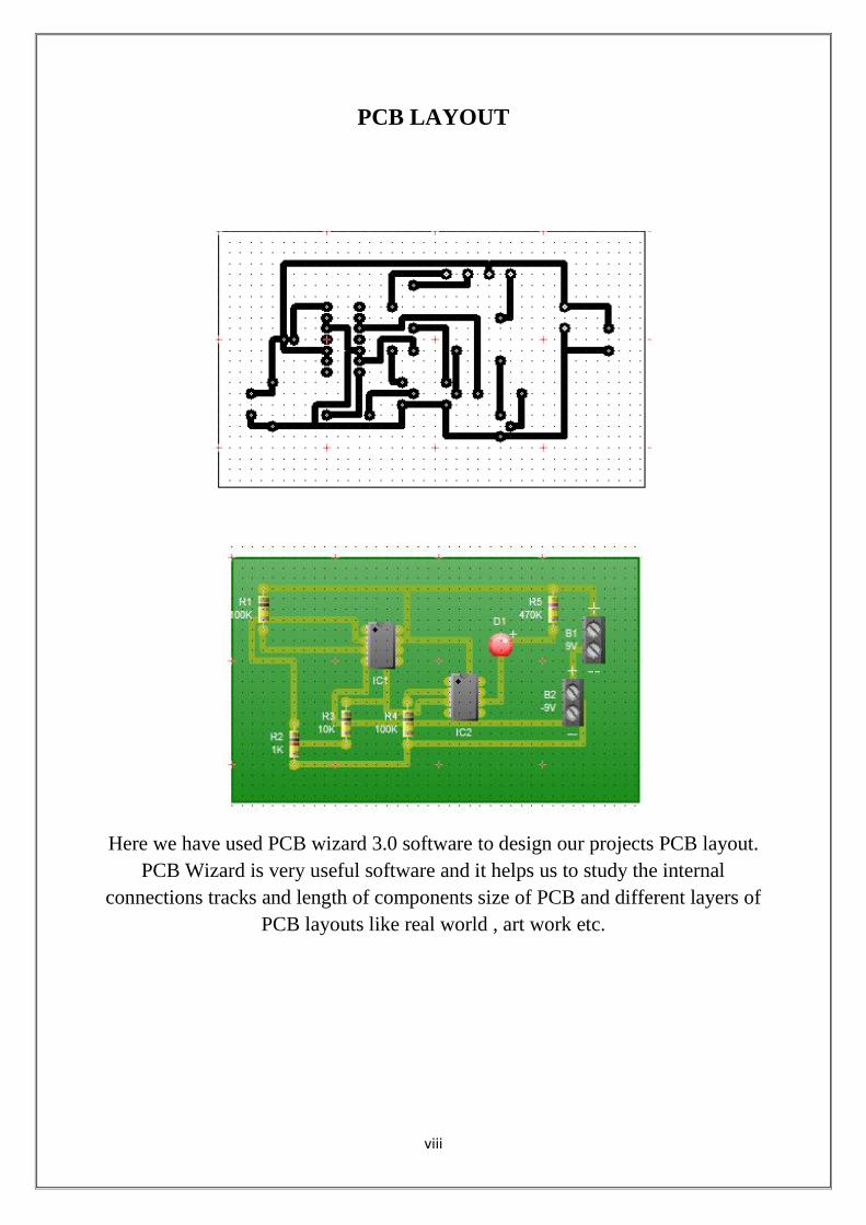
3 PCB Layout viii
4 Component List ix
5 Application x
6 Conclusion xi
7 Datasheet xii
8 References xvi
vi
INTRODUCTION
Occasionally you need a continuity test between two points in an electronic
circuit. Unfortunately, most continuity testers are prone to "lie". They don't do
that deliberately, but if they see a small resistance, they still tell you that you
have continuity. They just don't know any better.
This unit is different. If you have continuity it will tell you so. And if you're
reading even a low resistance through a component, the unit will tell you that as
well.
A continuity tester is an item of electrical test equipment used to determine if an
electrical path can be established between two points; that is if an electrical
circuit can be made. The circuit under test is completely de-energized prior to
connecting the apparatus.
The tester consists of an indicator in series with a source of electrical power -
normally a battery, terminating in two test leads If a complete circuit is
established between the test-leads, the indicator is activated. The indicator may
be an electric light or a buzzer. This led to the term "buzzing out a circuit"
which means to test for continuity. Audible continuity buzzers or beepers are
built into some models of multimeter.
For situations where continuity testing must be done on high resistance circuits,
or where delicate conductors and sensitive components that might be damaged
by excessive current are present, a low voltage, low current device must be
used. These typically use an op-amp and watch batteries to drive an LED as an