Page 1
- 1 -
UNIVERSITY OF NAIROBI
COLLEGE OF ARCHITECTURE AND ENGINEERING
DEPARTMENT OF ELECTRICAL AND ELECTRONICS ENGINEERING
PROJECT TITLE: UPRATING OF TRANSMISSION LINES-A CASE STUDY OF
132KV DANDORA – JUJA RD LINES I & II
PROJECT INDEX: 105
NAME: WANGARI KEITH MACHARIA
REG. NO.: F17/40182/2011
SUPERVISOR: DR. C. WEKESA
EXAMINER: PROF. M. MANG’OLI
Project report submitted in partial fulfillment of the requirement for the award of
Bachelor of Science Degree in Electrical and Electronic Engineering of the
University of Nairobi.
DATE OF SUBMISSION: 16TH MAY 2016
Page 2
- 2 -
DECLARATION OF ORIGINALITY
1) I understand what plagiarism is and I am aware of the university policy in this
regard.
2) I declare that this final year project report is my original work and has not been
submitted elsewhere for examination, award of a degree or publication. Where other
people’s work or my own work has been used, this has properly been acknowledged
and referenced in accordance with the University of Nairobi’s requirements.
3) I have not sought or used the services of any professional agencies to produce this
work
4) I have not allowed, and shall not allow anyone to copy my work with the intention
of passing it off as his/her own work.
5) I understand that any false claim in respect of this work shall result in disciplinary
action, in accordance with University anti-plagiarism policy.
Signature:
……………………………………………………………………………………
Date:
……………………………………………………………………………………
Page 3
- 3 -
DEDICATION
I dedicate this to my family, friends and all those who helped me through. Thank you for
your unwavering love and support.
Page 4
- 4 -
ACKNOWLEDGEMENT.
I would like to acknowledge the department of Electrical and Information Engineering
for entrusting me with this project. I thank my supervisor, DR. C. Wekesa for guiding
me throughout this endeavour. His insightful guidance cannot go unmentioned.
I would also like to thank my family for their hard work and dedication in ensuring
that I have the chance to pursue this degree.
I would also like to thank my friends and fellow classmates who believed in me and
encouraged me to always push on.
Last but not least, I would like to thank God for the gift of life, health and all the
blessings that have enabled me to come this far and to finish this project.
Page 5
- 5 -
TABLE OF CONTENTS
Contents UNIVERSITY OF NAIROBI ............................................................................................................. - 1 -
DECLARATION OF ORIGINALITY .......................................................................................................... - 2 -
DEDICATION ........................................................................................................................................ - 3 -
ACKNOWLEDGEMENT. ........................................................................................................................ - 4 -
TABLE OF CONTENTS ........................................................................................................................... - 5 -
ABSTRACT ............................................................................................................................................ - 7 -
1 CHAPTER 1................................................................................................................................... - 8 -
1.1 Introduction ........................................................................................................................ - 8 -
1.2 Main objective .................................................................................................................... - 9 -
1.3 Specific objective ................................................................................................................ - 9 -
1.4 Problem statement ........................................................................................................... - 10 -
2 CHAPTER 2: LITERATURE REVIEW. ............................................................................................ - 12 -
2.1 Growth in demand for power in the past present and the near future ........................... - 12 -
2.2 Right of way hinderances (ROW) ...................................................................................... - 12 -
2.3 Methods of increasing power flow through a transmission line. ..................................... - 13 -
2.3.1 Definition of uprating/upgrading. ............................................................................. - 13 -
2.3.2 Use of series capacitors and FACTS devices. ............................................................. - 14 -
2.3.3 Construction of high surge impedance line. ............................................................. - 16 -
2.3.4 Enhanced system and equipment monitoring .......................................................... - 17 -
2.3.5 Conversion of 3-phase systems to 6-phase systems. ............................................... - 17 -
2.4 Expanding Existing Transmission Capacity Technology .................................................... - 17 -
2.5 Fundamentals of Power Transfer Limits ........................................................................... - 18 -
2.5.1 Surge Impedance Loading ......................................................................................... - 18 -
2.5.2 Thermal Limits ........................................................................................................... - 19 -
2.5.3 System Limits ............................................................................................................ - 20 -
2.5.4 Increasing Thermal Limits ......................................................................................... - 20 -
2.5.5 Improved Transmission Structures ........................................................................... - 21 -
2.5.6 Uprating .................................................................................................................... - 21 -
2.6 Conductor hardware and accessories ............................................................................... - 47 -
Page 6
- 6 -
2.7 Conductor selection .......................................................................................................... - 47 -
3 CHAPTER 3.METHODOLOGY ..................................................................................................... - 50 -
3.1 Introduction ...................................................................................................................... - 50 -
3.2 Formulation ....................................................................................................................... - 50 -
3.2.1 Overhead line rating calculations ............................................................................. - 50 -
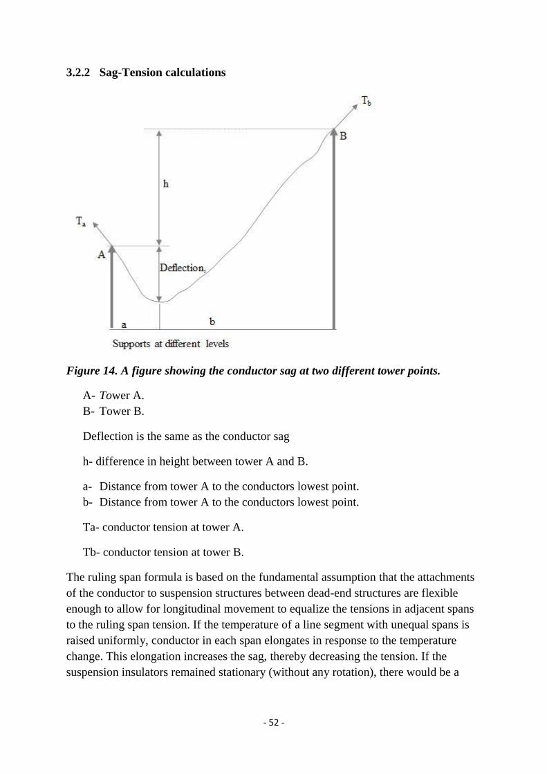
3.2.2 Sag-Tension calculations ........................................................................................... - 52 -
4 CHAPTER 4: RESULTS AND DISCUSSION .................................................................................... - 54 -
4.1 Results ............................................................................................................................... - 54 -
4.2 Discussion .......................................................................................................................... - 59 -
5 CHAPTER 5: CONCLUSION AND RECOMMENDATION ............................................................... - 61 -
5.1 Conclusion ......................................................................................................................... - 61 -
5.2 Recommendation .............................................................................................................. - 61 -
6 References ................................................................................................................................ - 62 -
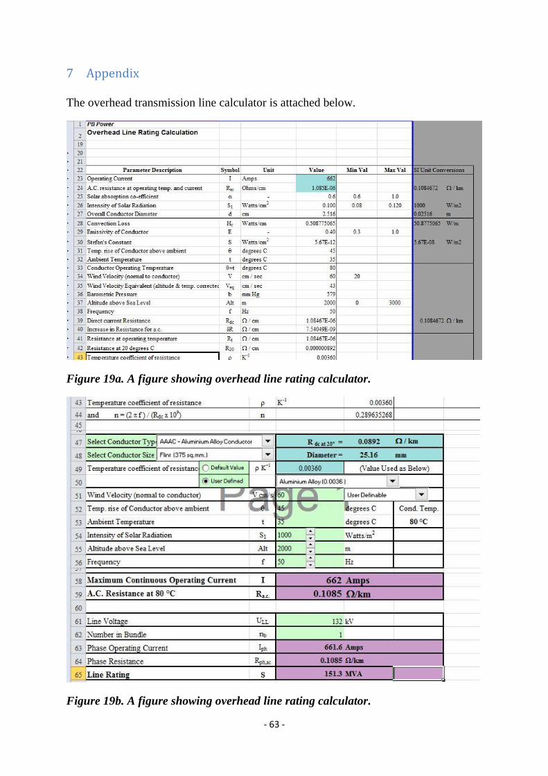
7 Appendix ................................................................................................................................... - 63 -
8 Abbreviations ............................................................................................................................ - 66 -
Page 7
- 7 -
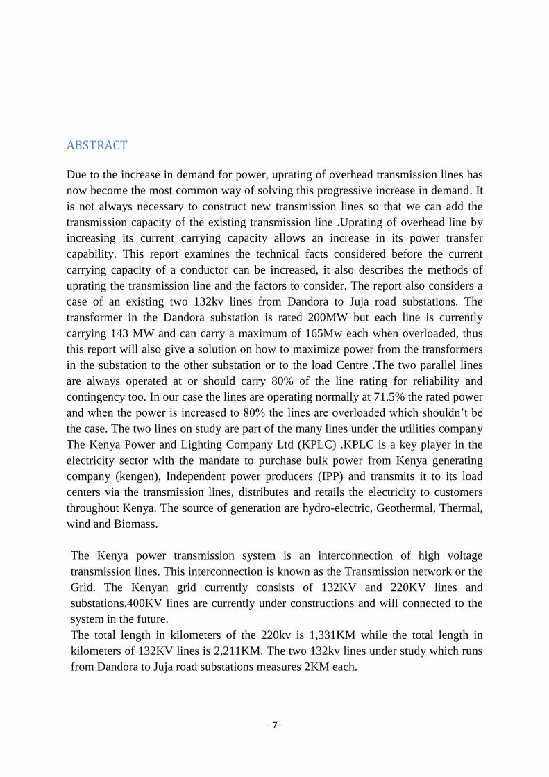
ABSTRACT
Due to the increase in demand for power, uprating of overhead transmission lines has
now become the most common way of solving this progressive increase in demand. It
is not always necessary to construct new transmission lines so that we can add the
transmission capacity of the existing transmission line .Uprating of overhead line by
increasing its current carrying capacity allows an increase in its power transfer
capability. This report examines the technical facts considered before the current
carrying capacity of a conductor can be increased, it also describes the methods of
uprating the transmission line and the factors to consider. The report also considers a
case of an existing two 132kv lines from Dandora to Juja road substations. The
transformer in the Dandora substation is rated 200MW but each line is currently
carrying 143 MW and can carry a maximum of 165Mw each when overloaded, thus
this report will also give a solution on how to maximize power from the transformers
in the substation to the other substation or to the load Centre .The two parallel lines
are always operated at or should carry 80% of the line rating for reliability and
contingency too. In our case the lines are operating normally at 71.5% the rated power
and when the power is increased to 80% the lines are overloaded which shouldn’t be
the case. The two lines on study are part of the many lines under the utilities company
The Kenya Power and Lighting Company Ltd (KPLC) .KPLC is a key player in the
electricity sector with the mandate to purchase bulk power from Kenya generating
company (kengen), Independent power producers (IPP) and transmits it to its load
centers via the transmission lines, distributes and retails the electricity to customers
throughout Kenya. The source of generation are hydro-electric, Geothermal, Thermal,
wind and Biomass.
The Kenya power transmission system is an interconnection of high voltage
transmission lines. This interconnection is known as the Transmission network or the
Grid. The Kenyan grid currently consists of 132KV and 220KV lines and
substations.400KV lines are currently under constructions and will connected to the
system in the future.
The total length in kilometers of the 220kv is 1,331KM while the total length in
kilometers of 132KV lines is 2,211KM. The two 132kv lines under study which runs
from Dandora to Juja road substations measures 2KM each.
Page 8
- 8 -
1 CHAPTER 1
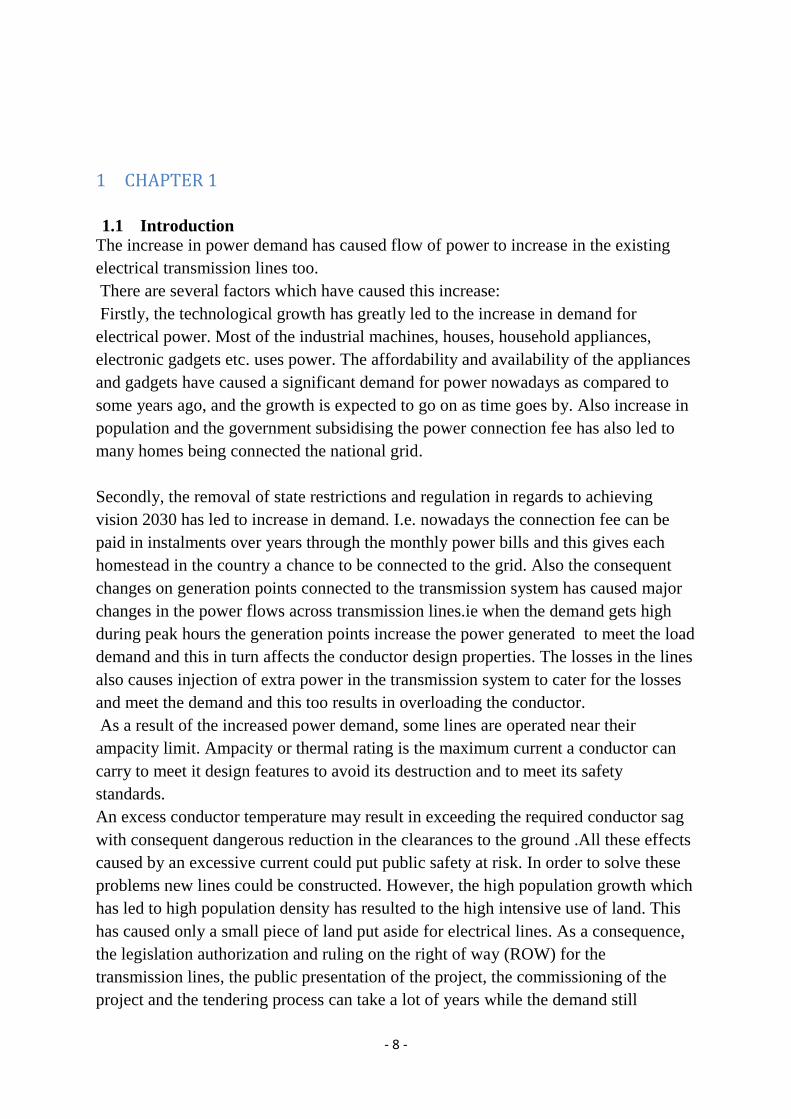
1.1 Introduction
The increase in power demand has caused flow of power to increase in the existing
electrical transmission lines too.
There are several factors which have caused this increase:
Firstly, the technological growth has greatly led to the increase in demand for
electrical power. Most of the industrial machines, houses, household appliances,
electronic gadgets etc. uses power. The affordability and availability of the appliances
and gadgets have caused a significant demand for power nowadays as compared to
some years ago, and the growth is expected to go on as time goes by. Also increase in
population and the government subsidising the power connection fee has also led to
many homes being connected the national grid.
Secondly, the removal of state restrictions and regulation in regards to achieving
vision 2030 has led to increase in demand. I.e. nowadays the connection fee can be
paid in instalments over years through the monthly power bills and this gives each
homestead in the country a chance to be connected to the grid. Also the consequent
changes on generation points connected to the transmission system has caused major
changes in the power flows across transmission lines.ie when the demand gets high
during peak hours the generation points increase the power generated to meet the load
demand and this in turn affects the conductor design properties. The losses in the lines
also causes injection of extra power in the transmission system to cater for the losses
and meet the demand and this too results in overloading the conductor.
As a result of the increased power demand, some lines are operated near their
ampacity limit. Ampacity or thermal rating is the maximum current a conductor can
carry to meet it design features to avoid its destruction and to meet its safety
standards.
An excess conductor temperature may result in exceeding the required conductor sag
with consequent dangerous reduction in the clearances to the ground .All these effects
caused by an excessive current could put public safety at risk. In order to solve these
problems new lines could be constructed. However, the high population growth which
has led to high population density has resulted to the high intensive use of land. This
has caused only a small piece of land put aside for electrical lines. As a consequence,
the legislation authorization and ruling on the right of way (ROW) for the
transmission lines, the public presentation of the project, the commissioning of the
project and the tendering process can take a lot of years while the demand still
Page 9
- 9 -
continues to increase therefore there is great pressure to increase the power flow in
existing right of ways using existing infrastructure as far as possible. Traditionally, the
upgrading of the line has been used in order to increase the line rating. The upgrading
involves increasing the line voltage or the number of conductors. The main problem of
these methods is the need to strengthen the towers. For this reason, methods without
the need to strengthen the towers that allow to increase line power flow securely and
safely, close to its ampacity limit, have been developed .One of the option is to
increase the ampacity of the line by conductor replacement. The new conductor needs
to have better properties as compared to the previous one such as lower sag-
temperature relations. I.e. the conductors sag isn’t affected much by the line
temperature. Another solution is real time monitoring of the conductor where factors
such as weather conditions i.e. wind and ice loading conditions in areas which
experiences winter are considered, conductor temperature, sag and tension are also
considered.
1.2 Main objective
One of the major reasons for uprating an existing transmission line is to maximize
utilization of the existing corridor for transfer of power. In situations where
construction of new lines is obstructed by the presence of ecologically sensitive areas,
forests or urban habitations, uprating of the existing transmission line is one of the
most appropriate solutions to meet the power flow requirements. In this project the
main objective is to uprate the existing 132kv Dandora – Juja road lines I & II which
currently have 400mm² ACSR (Aluminium core steel reinforced) conductor and
replace it with similar or small size of conductor which has almost twice the current
capacity of ACSR. This will be a high temperature-low sag conductor (HTLS) or high
capacity conductor.
Below are examples of HTLS conductors:
1. Aluminium Conductor Composite Core (ACCC) conductor.
2. Aluminium conductor core reinforced (ACCR) conductor.
3. Aluminium conductor steel supported conductor (ACSS) conductor.
4. GAP(Aluminium-zirconium strands which are steel reinforced)
conductor
They all have better thermal characteristics as compared to ACSR conductor
1.3 Specific objective
In situations where demand for power is increasing or is expected to increase in the
near future, it is highly recommendable to increase the power flow capacity of the
existing transmission line in the corridor through uprating rather than to construct a
new line. This can enable achievement of the required power demand at a very less
cost and in a very short duration as compared to construction of new lines. In this case
Page 10
- 10 -
study the maximum power that each line should carry is 200 MW, currently the line
carries 143MW due to thermal constraints. Since the transformers at Dandora
substation are rated 200 MW each, there is no power increase planned in near future
hence the need to uprate the two lines to Juja Road substation.
1.4 Problem statement
Challenge caused by increase in demand for affordable electricity has caused many
system planners and transmission engineers to try hard to find economical ways to
reduce grid congestion and improve grid reliability. In many cases, grid congestion
costs the utilities and the customers they serve millions of shillings annually
.Restrictions on permitting new lines and advances in conductor and related
technologies have changed the options available to planners and engineers trying to
solve these problems until now. However, there have been limited design tools
available that can help to show the differences between multiple conductor solutions.
Power grid congestion is a situation where the existing transmission line or
distribution line is unable to accommodate the required load during high demand
periods. Grid congestion affects the reliability and also causes a decrease in efficiency
because line losses increases greatly under high load conditions. If the transmission
lines are operated near their thermal limits, there would be a substantial loss during
high load conditions. An example of this was in 2004 in the western US where
congested transmission lines in California were unable to carry low-cost hydroelectric
power from the northwest to the southwest.
In addition to grid congestion, which is typically a function of a transmission
conductor's propensity to sag as it heats up because of its electrical resistance and
thermal properties, congested transmission lines also impact grid reliability. Should an
adjacent line fail or be taken out of service, the lines that remain in service can quickly
become overloaded. This can lead to a cascading outage, as was observed in the
eastern US in 2003. Current North American Electric Reliability Corp. (NERC)
initiatives may be further tightening acceptable conductor sag limits as it has become
apparent, in many cases, that aged conductors and ever changing under-build may
compromise safe clearances.
One of the most economical ways of addressing congestion is the use of a high-
capacity or high-temperature conductor. A widely adopted high-capacity conductor,
Aluminum Conductor Composite Core (ACCC), uses a high-strength, light-weight
carbon and glass fiber core that have a low coefficient of thermal expansion, virtually
eliminating thermal sag. The core's decreased weight compared to a steel core also
allows the incorporation of some 28 percent more aluminum in any given conductor
size. The added aluminum content decreases conductor resistance, so even under
heavily loaded conditions line losses are minimized.
Page 11
- 11 -
An ACCC conductor can carry twice the current of a conventional aluminum
conductor steel reinforced (ACSR) conductor. While an aluminum conductor steel
supported (ACSS)-high temperature version of ACSR-conductor is also capable of
carrying twice the current of a conventional ACSR conductor, because of its electrical
resistance, it does so at much higher operating temperatures. In many cases the ACSS
conductor's thermal sag can prevent its higher capacity from being fully realized. In
either case, under any load condition, the ACCC conductor's added aluminum content
and decreased resistance reduces line losses by 30 to 40 percent or more.
The ACCC conductor's high strength, low coefficient of thermal sag, superior self-
damping and resistance to load fatigue, corrosion resistance and other attributes can
help improve project economics on new and reconductoring projects in any
environment. Using ACCC to increase the capacity of an existing line can reduce or
eliminate the need to reinforce existing structures, which can save millions of shillings
and permitting challenges. For new lines, using ACCC can allow greater spans
between fewer and shorter structures, saving time and money, along with the added
and long-term energy efficiency benefits.
While increased capacity and reduced thermal sag have obvious advantages as
reduced line losses also translate into large savings for the utility company, the
consumer and the environment. When projects are considered as a whole, the early
choices made by planners and engineers can reduce the number of new structures or
modifications to existing towers, resulting in project savings that often exceed the cost
of the conductor entirely.
Page 12
- 12 -
2 CHAPTER 2: LITERATURE REVIEW.
2.1 Growth in demand for power in the past present and the near future
The increase in population growth, improved standards of living and advanced
technology in the country has caused a great rise in demand for power in the recent
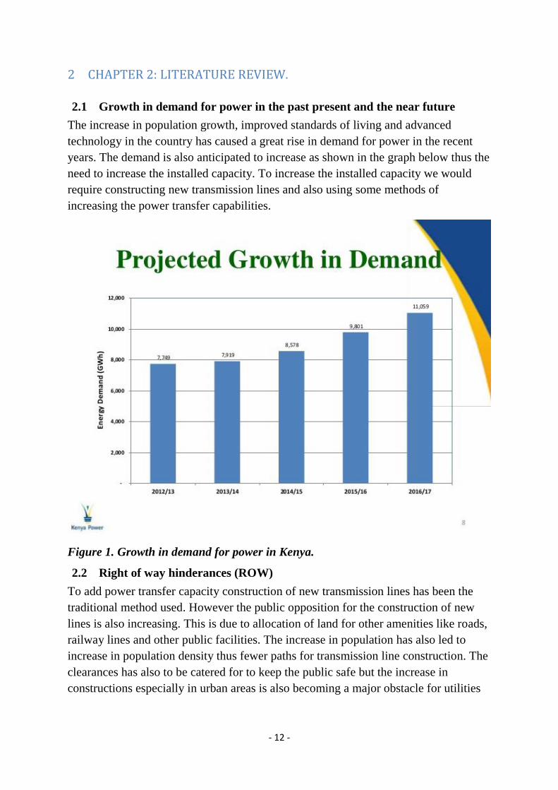
years. The demand is also anticipated to increase as shown in the graph below thus the
need to increase the installed capacity. To increase the installed capacity we would
require constructing new transmission lines and also using some methods of
increasing the power transfer capabilities.
Figure 1. Growth in demand for power in Kenya.
2.2 Right of way hinderances (ROW)
To add power transfer capacity construction of new transmission lines has been the
traditional method used. However the public opposition for the construction of new
lines is also increasing. This is due to allocation of land for other amenities like roads,
railway lines and other public facilities. The increase in population has also led to
increase in population density thus fewer paths for transmission line construction. The
clearances has also to be catered for to keep the public safe but the increase in
constructions especially in urban areas is also becoming a major obstacle for utilities
Page 13
- 13 -
companies. Environmental factors and acquiring legal rights for overhead
transmission lines have also become a challenge too.
2.3 Methods of increasing power flow through a transmission line.
The following are methods of increasing power flow through a transmission line:
1) Uprating of transmission lines.
2) Upgrading of transmission lines.
3) Use of series capacitors and FACTS (flexible alternating current transmission
systems) devices.
4) Construction of high surge impedance line such as expanded bundle, compact
lines.
5) Enhanced system and equipment monitoring.
6) Conversion of 3-phase systems to 6-phase systems.
2.3.1 Definition of uprating/upgrading.
Power flow in a 3-phase system is given by P=√3*V*I.
Where: V is the line voltage.
I is the line current.
Thus the power flow in a transmission line can either be increased by increasing the
line voltage V or the line current I.
The modification of line that results to a higher current carrying capacity is referred to
as thermal uprating and the modification of the line that allows the line to operate at a
higher voltage is referred to as voltage upgrading.
2.3.1.1 Reasons for uprating/upgrading.
The main reason for uprating/upgrading a transmission line is to fully utilize the
existing path for transfer of power. In circumstances where construction of new lines
is hindered by ROW issues, ecologically sensitive areas, forests and even urban areas,
uprating /upgrading the existing transmission line is the most economical method of
increasing the power transfer capability of the transmission line.
Also in areas where the power demand is expected to grow in the future, it is highly
advisable to increase the power flow of any existing transmission line through
uprating or upgrading rather than construction of a new line. This can help in
achieving the power demand cheaply and in less time.
2.3.1.2 Comparison between uprating and upgrading.
Uprating is the best solution for increasing the power carrying capacity of a
transmission line where power flow is limited by thermal limitations such as in short
Page 14
- 14 -
lines where power flow is as much as twice the Surge Impedance Loading (SIL). In
transmission lines where stability reasons is the main concern especially in the long
lines, the increase in the power carrying capacity of the line is solved through
upgrading .Increasing the line voltage also reduces the line per unit reactance.
Upgrading also leads to a reduction in the voltage drop along the line thus improves
the voltage control. Upgrading also leads to an increase in MVA rating of the
transmission line in relation to uprating. However upgrading requires more capital
investment, more power outage time for construction thus resulting in poor reliability
and also replacement of some substation equipment. This is because the electrical
clearance of the line will have to be increased to cater for the increased sag if the same
conductor is to be used. The existing structure will also need some modification to
cater for clearances between the conductors. Thus it is advisable to prioritize uprating
to upgrading if the reliability, time and cost factors are to be considered.
The substation is already rated at 132KV and there is no expected increase in the line
voltage thus this also positions uprating of the line as the best method to increase the
power transfer capability.
2.3.2 Use of series capacitors and FACTS devices.
2.3.2.1 Series capacitors.
The use of series capacitors for compensation part of the inductive reactance of long
transmission line will increase the transmission line capacity. It also increases the
transient stability margins, optimizes load sharing between parallel transmission lines
and reduces the overall system losses.
Transmission line compensation means modification in electric properties of the
transmission line to increase the power transfer capability.
In series compensation, the main objective is to reduce the transfer reactance of the
line at power frequency by means of series capacitors. This increases the system
stability which in turn increases the power transfer capability of the line.
Series capacitors can be connected at one or both ends of the line. The line ends are
the locations of the capacitors. Mid-point series compensation is more effective in the
case of very long transmission lines. Series capacitors located at the line ends create
more complex protection problems than those installed at the center of the line. The
power transfer along a transmission line is shown below:
Page 15
- 15 -
Figure 2. Transmission line without series compensation
The active power over the uncompensated transmission line is given by
P= (𝐸𝑆∗𝐸𝑅
𝑋𝑡)* sin ð
Where:
ES- sending end voltage
ER- receiving end voltage
Xt- transfer reactance of the transmission line
ð – Load angle.
Higher voltage gives higher power flow limit. Higher voltage for the same power
gives lesser current thus reducing I²R losses. Series compensation has been applied to
mostly long transmission lines and other locations where the transmission distances
are great and where large power transfers over this distances is required.
Modern high voltage and extra high voltage transmission lines are series compensated
to improve the power system performance, to enhance power transfer capacity, to
enhance power flow control and voltage control and to decrease the capital
investment.
Figure 3. Transmission line with series compensation.
The active power transferred by the compensated transmission line is given by:
P= (𝐸𝑆∗𝐸𝑅
𝑋𝑡−𝑋𝑐)* sin ð
Page 16
- 16 -
The effects of series compensation are:
The lower line impedance improves the system stability.
The lower line impedance improves the voltage regulation.
Adding the series capacitance provides a method of controlling the division of
load among several lines.
Increasing the loading capacity of a line improves the utilization of the
transmission system and therefore returns on the capital investment.
Increase in power capacity as compared to uncompensated line.
2.3.2.2 FACTS based devices
A flexible alternating current transmission system (FACTS) is a system composed of
static equipment used for the A.C transmission of electrical energy. It enhances
controllability and increases the power transfer capability of the network.
In series compensation, the facts based device is connected in series with the power
system. It works as a controllable voltage source. All transmission lines experiences
series inductance. When a large current flow this causes a large voltage drop and to
compensate this, series capacitors are connected to decrease the effect of inductance.
It also improves the power factor.
In shunt compensation the power system is connected in shunt with the FACTS. It
works as a controllable current source.
2.3.3 Construction of high surge impedance line.
The magnitude of power that a given transmission line can carry safely depends on
various factors. These factors can be categorized into thermal and surge impedance
loading limits. For long lines the capacity is limited by its SIL level. A decrease in line
inductance and surge impedance would in turn increase the surge impedance loading
(SIL) which would result in increase in power transfer capability.
The surge impedance which is also known as the characteristic impedance is given by
the equation below.
Zo= √𝐿
𝐶
Where: L is the per unit impedance.
C is the per unit capacitance.
The SIL is equation is shown below
SIL (MVA) = √𝑉𝐿𝐿2
𝑍ₒ
Page 17
- 17 -
VLL is the line-line voltage of the transmission line.
2.3.4 Enhanced system and equipment monitoring
Installation of tension and sag monitors can help in monitoring the transmission line.
On a cool windless day when the air temperature and wind speed is low, and there is
no sun, the MVA rating may be higher than that of a hot windy day. The line rating
will vary in such a way that is partly predictable or partly random. Also the load
variation monitoring can help in determining when the lines will carry their maximum
limits. I.e. During peak times the demand is high thus the lines can be put to their
maximum capacity while during off-peak times when the demand is low the lines can
be operated below their limits. Thus the power transfer capability is maximized only
when the demand is high.
2.3.5 Conversion of 3-phase systems to 6-phase systems.
Six phase system is one of the multiphase power systems. Due to harmonics effects
and some other reasons six phase systems and six phase machines are not common but
six phase transmission lines are popular due to the following reasons:
1. Increased power transfer capability.
2. Better voltage regulation.
3. Better efficiency.
4. Greater stability and reliability.
2.4 Expanding Existing Transmission Capacity Technology
Complex technology is necessary to increase the power flow capacity on existing
power equipment (overhead lines and power transformers), power circuits (multiple
power equipment elements in series), and power system interfaces (multiple parallel
power circuits connecting power system regions). The following three issues are basic
to all approaches:
1. For overhead lines, increase in power flow capacity is dependent on line length,
original design, environmental regulations, the condition of structures and the type of
conductors used. Increase in a line’s thermal rating could range from between 5% to
100%.
2. Overhead lines are only part of the transmission line path (circuit). The lines are
terminated at substations by air disconnects, circuit breakers, and line traps. The
power flow through all of the circuit elements must be limited to avoid damaging the
line or the terminating equipment. The maximum allowable power flow over this
circuit may be limited by any one of the circuit elements. According to the currently
Page 18
- 18 -
used rating method, a facility rating must be the minimum of all ratings between
substations.
3. Increase in maximum allowable power flow through a component circuit or circuit
element does not necessarily yield a higher rating. This is because increased power
flow on an improved element may interfere with another element’s limits.
Transmission circuit ratings are often developed on a system basis, rather than on an
individual line basis. This is because the maximum power flow on the transmission
system is a function of the overall system topology (transmission lines, transformers,
generation, series and shunt compensation, and load). Many non-thermal system
considerations (such as sag, tension and voltage) can also limit the maximum power
flow on a specific transmission circuit. The overall limit may be set between operating
areas, irrespective of ownership or individual lines, and may change during a day
based on system conditions. Increasing the capacity on a single line by 100% would
not necessarily increase the system capacity by this amount. A separate parallel
facility may have a constraint after the flow increases by only 25%.
2.5 Fundamentals of Power Transfer Limits
The following describe technical aspects of electric power transfer that will help those
evaluating alternative strategies for increasing the transfer capability of the grid.
2.5.1 Surge Impedance Loading
The surge impedance loading (SIL) of a power transmission line is the nominal power
flow capacity based on the design characteristics for the line and its operating voltage.
SIL is governed more by the overall geometry of the line and its operating voltage and
less by the conductor size. SIL is independent of the line length. SIL is not the
maximum that a particular line can carry, but rather a benchmark that can be used to
compare lines of different designs and voltage rating. SIL is a useful concept to
compare different transmission lines.
SIL (MVA) = √𝑉𝑙𝑙2
𝑍ₒ
VLL is the line-line voltage of the transmission line.
Zₒ is the lines characteristic impedance which is a function of the line’s inductance
and capacitance.
For an overhead transmission line, typical surge impedance is around 300 ohms,
compared to a cable, which may be 50 ohms or less. At 345 kV, the SIL of an
overhead line is on the order of 400 MW. Short lines may be able to carry 800 MW or
more. Long lines of the same construction may be limited to less than 400 MW by
system considerations. Underground transmission cables always operate very far
Page 19
- 19 -
below SIL because of limitations on heat dissipation. As a result, underground
transmission cables are a net source of reactive power (vars) to the system.
Reactive loading and losses can become a limiting problem if a significant number of
the lines are loaded above their SIL. As loading increases appreciably above SIL for
many lines in the system, the reactive losses will increase in relation to the square of
the current and the line reactance. Adding high-capacity lines instead of improving the
power transfer capability of the system could further increase the reactive losses and
consequently further hinder power transfers.
2.5.2 Thermal Limits
Thermal limits are the maximum flows that can be permitted through a transmission
circuit, either on a continuous basis or for a short duration, based on the circuit design.
The design parameters include the conductor type, conductor bundles, ambient
temperature, wind speed, ice loading, and span length. The thermal limitation is
critical in cases of lower voltage lines of 80 km or less.
At extra-high voltage (345 kV and above), environmental considerations, such as
corona discharge and field effects, dictate line designs and usually result in high
thermal capabilities, which can exceed the realistic power transfer. For extra-high
voltage transmission, line terminating equipment, such as wave traps and substations,
impose a thermal limit rather than the line itself. Consequently, thermal limits are
significant only for short lines at 138 kV and below.
The process of selecting a thermal rating for an overhead line can be fairly complex or
simple. Ratings are published by conductor manufacturers for a range of conservative
weather assumptions and conductor temperature limits. Ratings can also be
determined from field measurements of sag, wind direction and strength, solar
insolation, and other variables.
As power flow increases in a bare overhead power line, the conductors, connectors,
and associated hardware are heated because of the ohmic losses. Typically, lines that
are thermally limited are the shorter lines in the system and the economic cost of
electrical losses may be tolerable. However, potential damage to conductor systems or
safety concerns occasioned by violation of minimum clearances remains a concern
and must be catered for.
Thermal ratings for overhead lines are defined in amperes or megavolt amperes
(MVA) with an associated duration and, possibly, by frequency of occurrence.
Consequently, one line may have a continuous thermal rating of 100 MVA; a 4-hour,
long-time emergency rating of 115 MVA; and a 15-minute, short-time emergency
rating of 130 MVA. The system operator would understand these ratings to mean that
the power flow on this line could reach but not exceed 100 MVA indefinitely. Also, if
the flow exceeds 100 MVA, but is less than 115 MVA, the operator must reduce the
Page 20
- 20 -
flow to below 100 MVA within the next 4 hours. If the flow exceeds 115 MVA, the
operator must reduce it to below 100 MVA within 15 minutes. The temperature limits
on these lines typically serve to limit the loss of conductor tensile strength to less than
10% over the life of the line. It may be possible to exceed the thermal limits of lines
and accept some loss of life provided safe clearances are maintained especially for
lines that are scheduled for replacement or upgrade in the near future.
2.5.3 System Limits
System limits are functions of transmission line reactance in relation to the overall
power system. Series reactance, shunt admittance, and their combination can alter
system transfer limits. System planners have long recognized this relationship,
particularly where there are prospects of changing the line surge impedance, either by
adding equipment (e.g., series capacitors) or by modifying the line itself (e.g.,
reconductoring, voltage upgrading). Transmission line series inductive reactance is
determined by conductor size, phase spacing, number of conductors, relative phasing
(double-circuit lines), and line configuration. In long high-voltage overhead
transmission lines, the series reactance is larger than the series resistance and is
dominant. For this reason, simple reconductoring of many long transmission lines,
with no change to structure geometry, results in only minor changes in system power
flows.
2.5.4 Increasing Thermal Limits
The thermal limits of the conductor are the limiting factor in the capabilities of
transmission lines. As electricity flows through a transmission line, heat is produced
due to the flow of current through the resistance of the conductor. As the current
flowing through the conductor increases, additional heat is produced, which causes the
conductors temperature to increase. The temperature is a function of the electrical
current and the environmental conditions (temperature, humidity, and wind speed). If
the conductor becomes too hot, one of two problems may result.
1. Excessive heat may permanently damage the conductor. Each transmission line
has a maximum amount of power that can flow over it without damage.
2. Increasing temperature may cause the line to physically sag below design levels,
resulting in increased risk of injury to the public and conductor damage as well as
line outages. The line must not touch anything including the ground. Physical sag of
the line can be reduced by using certain types of conductors.
Other important constraints are the level of electric and magnetic fields produced
(e.g., electric fields increase as the conductor gets closer to the ground), the maximum
structure loads during occasional high wind and ice loads, and the maximum
temperature at which the energized conductors are allowed to operate. Given standard
Page 21
- 21 -
worst-case weather conditions, the thermal rating of an existing line is determined by
the maximum allowable conductor temperature. Thus, uprating (adding more current
to increase power transfer capability) such lines without reconductoring normally
requires getting ways to maintain electrical clearances above the ground when
operating at a higher conductor temperature. To protect against problems resulting
from thermal overloads on transmission lines utilities companies install relays. A relay
senses the amount of power flowing through a transmission line and operates a circuit
breaker to interrupt the power flow on the line. If it exceeds the thermal limit of the
line then the power will then flow through parallel paths. The increased loading along
the parallel paths creates the potential for an overload condition on other transmission
lines. If the system is not properly designed, operated, and maintained, thermal
overloads can lead to cascading outages of transmission lines and system breakup.
Transmission line capacity can be increased through improvements in transmission
tower design (to compensate for physical sag) and increases in conductor current
capabilities (to withstand more heat). The ability to accurately determine the
conductor thermal condition at any point in time (monitoring) is also helpful in
maintaining the line.
2.5.5 Improved Transmission Structures
Adaptations can be made to accommodate physical sag resulting from increased
transmission capacity on existing lines. Ground clearance on specific spans can be
increased by installing additional structures mid-span, if the ground contours and
permitting restrictions allow. Clearance can also be increased by modifying the
existing structures to raise the conductor attachment points. Digging the ground in
between the support structures can also be used as a method of increasing the
clearance. Alternatively existing structures can be replaced with taller structures.
These methods do not increase conductor tension, minimizing the need to replace
angle and dead-end structures. Increasing ground clearance typically results in only
modest increases in allowable ampacity (electricity through the line) before cost
becomes high.
2.5.6 Uprating
2.5.6.1 Basics of uprating
Thermal uprating is based on the fact that the tower structure / geometry, air gap
clearances and conductor bundle configuration are generally limited by the voltage of
the transmission line. If we keep the line voltage constant and we vary the line current
to a greater value we may be able to increase the power transfer capability of the
transmission line without possible need of changing the tower structure/ geometry.
Thermal uprating methods are cheapest and less time consuming as compared to other
methods.
Page 22
- 22 -
2.5.6.2 Methods of uprating.
Increase in ampacity of a transmission line may be achieved through the following
methods.
2.5.6.2.1 Increase conductor rating by changing the thermal rating criteria
The maximum operating temperature of an ACSR conductor can be reached
without getting to the annealing point of the aluminium strands. This results to
an increase in the MVA of the line.
The ACSR conductor experiences a loss in its composite strength if operated
above 95 ͦ C for an extended period of time. The strength of the steel core is not
affected for temperatures below 300 ͦ C. The increase in maximum sag of the
conductor due to an increase in the maximum operating temperature of around
5-10 ͦ C is only marginal. I.e. the approximate increase in sag is 0.2 m for 5 ͦ C
increase and 0.4 m for 10 ͦ C increase while the approximate increase in MVA
for a 400KV DC line is 150MVA and 300MVA respectively.
If the increase in sag of the transmission line lies within the safety margin,
there is no need for construction of a new tower structure or refurbishment of
the existing tower. The above method has an advantage which is:
There will be no purchase of any new conductor.
No line outages.
Thus it is therefore the most cost effective and effortless method of increasing the
MVA rating of a transmission line. If the electrical clearance corresponding to the new
higher current carrying conductor is not enough then the following should be done:
i. The supports structure must be raised.
ii. The conductor tension should be increased.
iii. The suspension clamp positions should be changed.
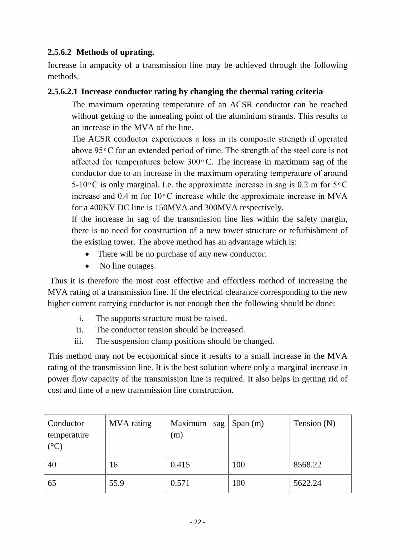
This method may not be economical since it results to a small increase in the MVA
rating of the transmission line. It is the best solution where only a marginal increase in
power flow capacity of the transmission line is required. It also helps in getting rid of
cost and time of a new transmission line construction.
Conductor
temperature
(°C)
MVA rating Maximum sag
(m)
Span (m) Tension (N)
40 16 0.415 100 8568.22
65 55.9 0.571 100 5622.24
Page 23
- 23 -
75 64.6 0.663 100 4659.04
Table 1. An indication in the variation in sag and MVA rating as a function of
conductor temperature.
The calculations were done considering an ambient temperature of 30 °C.
The conductor parameters were:
Stranding (No/diameter. mm) – 6/4.1 mm
Break load (N) -27200
Cross-sectional (area sq.mm) - 75
Modulus of elasticity (N/mm²) -79000
Coefficient of expansion- (I °C) – 1.91 * 10^-5
Weight (Kg/Km) – 320
Conductor diameter (mm) – 12.3
Calculating conditions:
Safety factor – 2
Radial ice thickness (mm) -0
Wind pressure (N/mm²) – 400
Initial conductor temperature (ͦ C) - 40
Page 24
- 24 -
Figure 4. A graph showing how an increase in temperature results to an increase in
MVA rating.
2.5.6.2.2 Dynamic environment rating.
Installation of tension and sag monitors can help in dynamic line rating. On a
cool windless day when the air temperature and wind speed is low, and there is
no sun, the MVA rating may be higher than that of a hot windy day. The line
rating will vary in such a way that is partly predictable or partly random.
The cost of monitoring the system may be a small percentage as compared to
the construction of a new line. It also has the advantage of no service outage.
This method does not change the maximum capacity of the existing conductor
but it allows the maximum utilization of the conductor.
Page 25
- 25 -
2.5.6.2.3 Increasing the conductor area
The increase in the aluminium or aluminium content of the existing conductor
results to a decrease in the conductor resistance.it is shown by the formula
below.
R= 𝜌𝐿
𝐴
Where: R is the resistance.
ρ is the conductor resistivity.
L is the conductor length.
A is the conductor area.
This result to an increase in ampacity of the conductor. It can be achieved by
the following two methods:
i. Adding new conductors to the existing conductor.
ii. Replacing the existing conductor with new conductor of different size
and shape.
ACSR Dog 100 sq.mm ACSR Zebra 400 sq.mm ACSR curlew 600 sq.mm
Temperature(°C) Current
(A)
Temperature(°C) Current
(A)
Temperature(°C) Current
(A)
50 194 50 395 50 432
75 335 75 774 75 869
100 421 100 998 100 1126
125 487 125 1167 125 1319
150 539 150 1304 150 1477
175 584 175 1423 175 1614
200 624 200 1529 200 1736
Table 2. How the increase in conductor size affects the current
carrying capability of a conductor at different working temperatures.
Page 26
- 26 -
Figure 5. A graph showing how conductor cross-sectional area affects its
current carrying capability.
2.5.6.2.3.1 There are certain factors to consider before increasing the conductor
area
a) The higher the conductor area the greater the weight. An increase in
conductor weight results to an increase in vertical load and an increase
in tension too if the conductors sag is to be limited. The increase in
tension will lead to tower reinforcement. The increased area may also
increase the wind loading on the conductor thus increasing the vertical
and transverse load on the tower structure. To get rid of increased outer
conductor’s diameter, conductor with trapezoidal strands can be used
instead of circular strands. In this conductor the aluminium area of the
conductor is increased without overall increase in diameter. This helps
in increasing the ampacity with less effect on mechanical loading of the
transmission line rather than using the latter.
Page 27
- 27 -
b) The increase in weight leads to an increase in the conductors sag. If the
conductor tension values are limited to those of the existing conductor,
the following can be done to cater for the increased sag:
Modifying the towers to increase clearance.
Installation of new towers in areas with critical spans.
Installation of negative sag devices along the conductor. The
device is altered by the changes in temperature. When there is an
increase in temperature, the conductor expands and there is an
increase in its length. The device changes geometrically to cater
for the increase in sag. As the conductor temperature decreases
the sag decrease too and the device retains its normal shape.
Excavation of key areas to increase ground clearance.
2.5.6.2.4 Reconductoring using a conductor of higher ampacity.
Reconductoring is the process of replacing the existing conductor with a higher
ampacity one so that the thermal rating of the existing transmission line can be
increased. Reconductoring using a conductor of larger diameter than the current one
can lead to an increase in wind loading. Increase in wind loading will require
improvement of the existing structure to cater for the excess weight. Reconductoring
using conductor with the same diameter as original conductor but with higher thermal
rating can lead to higher ampacity with no need to reinforce the existing tower and
structures.
Therefore the line rating is limited by the following factors:
• The properties of the conductor material
• The environmental conditions surrounding the conductor.
• The ground clearance of the line.
Today, most overhead transmission lines are aluminum conductor steel reinforced
(ACSR) conductors. Steel can withstand temperatures up to 300°C with no changes in
its properties. Aluminum, however, experiences deterioration in mechanical properties
(annealing) when the temperature is higher than 90°C. The temperature is a function
of the electrical current and the environmental conditions.
The replacement conductors can be classified into two categories:
1. Conductors to be operated at temperatures at moderated temperatures
(Temperatures < 100° C.)
2. Conductors to be operated at high temperatures (Temperatures >100° C.)
Page 28
- 28 -
2.5.6.2.4.1 Conductors for operation at moderate temperatures.
There are three types of conductors that operate at moderate temperatures:
a) AAAC (All aluminium alloy conductors).
b) Aluminium conductor aluminium alloy reinforced. (ACAR).
c) High conductivity AAAC.
The AAAC conductors have a higher strength to weight ratio as compared to
ACSR. If they are operated at the same percentage of the rated breaking strength
with ACSR, they can operate at a higher temperature than ACSR with the
maximum sag for the design catered for. Operating at the same percentage of rated
breaking strength however leads to much higher ratio of horizontal tension to the
conductor unit weight and this can cause problems to lines sensitive to vibration.
ACAR combines strands made from aluminium alloy and EC grade aluminium.
The use of EC grade aluminium increases the conductivity of the conductor. If the
number of the alloy strands is also increased, the mechanical strength of the
conductor is also increased. The use of ACAR to substitute ACSR depends mainly
on the allowable operating tension.
2.5.6.2.4.2 Conductors for operation at higher temperatures
By use of AAAC and ACAR conductors to replace ACSR conductor may not be
an economical solution since there is no much increase in current carrying capacity
of the transmission line as compared to the cost of replacing the line. Use of higher
operating temperatures conductors can be a better solution and can result in a
significant increase in thermal rating of the existing conductor; it is even twice in
some situations.
The conductors can be classified into two categories:
1. High temperature conductors
2. High temperature low-sag conductors
2.5.6.2.4.2.1 High temperature conductors
This type of conductors has the ability to operate at temperatures of at least 150°C.
Their sag increases linearly with increase in temperature. Among the most commonly
used high temperature conductors are:
2.5.6.2.4.2.1.1 TACSR (thermal resistant aluminium conductor steel
reinforced)
This conductor is made up of an inner steel core consisting of galvanized steel
wires and outer aluminium layers composed of aluminium-zirconium alloy
strands.
Page 29
- 29 -
Figure 6. A figure showing the cross sectional area of a TACSR conductor.
The aluminium alloy has a higher resistivity when compared to hard drawn aluminium
but it can be operated to temperatures of up to 210°C thus increasing the power
carrying capacity.
There are different types of aluminium alloy conductors used in the formation of this
conductor. The alloys have the following properties:
Aluminium
alloy.
Conductivity
(%)
Tensile
strength (MPa)
Continuous
operating
temperature
(°C)
Current
carrying
capacity (%)
EC 1350 61 160 85 100
TAL 60 160 150 160
This type of conductor finds applications in the following areas:
In transmission lines where the current levels have to be 1.5 to 1.6 times higher
than the capacity of a normal ACSR.
In overhead lines in areas where corrosion caused by contact of two different
metals may occur.
In overhead transmission lines where low sag is not a limiting factor.
In transmission lines which can be operated safely at a continuous temperature
of 150°C.
In reconductoring without necessarily modifying the tower.
Page 30
- 30 -
Table 3.The table below shows the technical comparison of ACSR panther
and TACSR conductor.
properties ACSR panther TACSR panther
Cross- sectional area (mm²) 262 262
Conductor Diameter (mm) 21 21
Weight (kg/km) 974 916
DC Resistance at 20°C temperature
(ohms/km)
0.139 0.12882
Maximum Operating Temperature
(°C)
75 150
Voltage Level (kV) 132 132
Line length (km) 1 1
Span (m) 325 325
Maintaining same ampacity in TACSR conductor
Calculation temperatures (°C) 75 73.43
Current to be maintained (A) 420 420
AC resistance (ohms/km) 0.1701 0.15658
Line losses (kw/circuit) 90 82.9
Power transferred (MW/circuit) 83.8 83.8
Ampacity at maximum operating temperature in TACSR conductor.
Calculation temperatures (°C) 75 150
Current (A) 420 893
AC resistance (ohms/km) 0.1701 0.196
Line losses (kw/circuit) 90 469
Power factor 0.9 0.9
Power transferred (MW/circuit) 83.8 178
Sag at the mentioned temperature
above and 0% wind (m)
7.244 9.81
Tension to be maintained at 32°c
and 100% wind.
4255 4253
The assumptions made:
Coefficient of emissivity= 0.6
Wind velocity = 0.6 m/s.
Solar absorption coefficient = 0.5
Average ambient temperature = 48°C.
Constant of mass temperature coefficient of
resistance of conductor per °C =0.004 for both
conductors.
Wind pressure = 117.96 kg/m².
Page 31
- 31 -
Solar radiation = 1200 W/m².
From the above table the following remarks can be made:
1) TACSR can operate at a maximum temperature of 150°C while ACSR
operates at 85°C thus this boosts the current carrying capacity by 112%.
The ACSR carries 420 Amps by while TACSR carries 893 Amps at
their maximum operating temperatures.
The difference in currents: 893-420=473A
(473
420) ∗ 100 = 112.6%
2) The power transferred in MW by TACSR conductor at its maximum
operating temperature is 112% higher than that of ACSR.
Maximum ACSR panther power at its maximum operating temperature
– 83.8 MW.
Maximum ACSR panther power at its maximum operating temperature
– 178 MW.
Difference 178-83.8=94.2 MW
(94.2
83.8) ∗ 100=112.4%
2.5.6.2.4.2.1.2 High conductivity AAAC conductor (Al59)
The high conductivity all aluminium alloy conductor made of aluminium –
magnesium-silicon alloy strands has been widely used by utilities companies in
the world.
This conductor can carry 25-30% more current as compared to ACSR conductor
of the same size while the sag remains the same and the working tension is lesser
than that of ACSR.it also has lower resistance than ACSR thus the losses are
reduced. It also has a higher corrosion resistance as compared to alloy series of
AAAC conductors.
When comparing AL59 conductor with conventional AAAC and ACSR
conductors, the following points can be made:
Its ultimate tensile strength is lesser when compared to the above
conductors but it can be strung in the same tension.
If the span and working tension is maintained as the same, it will have
lower sag as compared to the above conductors. Thus this conductor can
be used in uprating the existing lines or in construction of new lines.
The table below shows options for reconductoring existing ACSR with AL59
conductor.
Page 32
- 32 -
Table 4. The table below shows technical comparison of ACSR Dog and AL59
(19/2.84)
properties ACSR Dog AL59 (19/2.84)
Conductor Diameter (mm) 14.15 14.2
Weight (kg/km) 394 330
DC Resistance at 20°C temperature
(ohms/km)
0.2792 0.2457
Voltage Level (kV) 66 66
Line length (km) 1 1
Span (m) 250 250
Maintaining same ampacity in AL59 conductor
Calculation temperatures (°C) 75 71.83
Current to be maintained (A) 288 280
AC resistance (ohms/km) 0.34068 0.29543
Line losses (kw/circuit) 84.77 73.51
Ampacity at maximum operating temperature in both conductors.
Calculation temperatures (°C) 85 95
Current (A) 288 409
AC resistance (ohms/km) 0.34068 0.3176
Line losses (kw/circuit) 81 151
Power factor 0.9 0.9
Power transferred (MW/circuit) 28.74 40.81
Sag at the mentioned temperature
above and 0% wind (m)
5.255 5.84
Tension to be maintained at 32°c
and 100% wind.
2008 2008
The assumptions made:
Coefficient of emissivity= 0.6
Wind velocity = 0.6 m/s.
Solar absorption coefficient = 0.5
Average ambient temperature = 45°C.
Constant of mass temperature coefficient of
resistance of conductor per °C =0.004 for ACSR
and 0.0039 for AL59.
Wind pressure = 117.96 kg/m².
Solar radiation = 1200 W/m².
From the above table the following remarks can be made:
Page 33
- 33 -
1. The weight of AL59 conductor in kg/km is 16.24% less as compared
to the ACSR conductor.
Al 59 weight per km – 330
ACSR dog weight per km- 394
Difference: 394-330=64 64
394*100=16.24%
The decrease in weight shows that there is no need for structure
modification when reconductoring.
2. The DC resistance at temperature of 20°C of AL59 conductor is 12%
lesser as compared to that of ACSR thus increasing AL59’s ampacity
while reducing its line losses.
ACSR dog D.C resistance at 20°C – 0.2792
AL 59 D.C resistance at 20°C- 0.24750
Difference: 0.2792-0.24750=0.0317 0.0317
0.2792∗ 100=11.35%.
3. While maintaining the same ampacity, the line losses of AL59
conductor are 13.28% lesser when compared to that of ACSR.
ACSR dog line losses -84.77
AL 59 line losses -73.51
Difference: 84.77-73.51=11.26 kW. 11.26
84.77∗ 100=13.28%
4. When both conductors are operated at their maximum temperatures,
AL59 conductor carries 42% more current when compared to ACSR
conductor.
ACSR dog current- 288
AL 59 current -409
Difference: 409-288=121 121
288∗100= 42.01%.
5. The power transferred by the AL59 conductor is 42% more than that
of the ACSR conductor at their maximum operating temperature.
The power transfer at maximum operating currents.
ACSR dog-28.74 MW/cct
AL 59- 40.81
Difference: 40.81-28.74=12.07 MW/cct
12.07
28.74*100=41.99%
Page 34
- 34 -
6. While maintaining the tension of ACSR at 32° and 100% wind, the
increase in sag is 0.585 for an increase in 121 amperes.
The difference in sag between ACSR dog and AL 59 at maximum
temperature and 0% wind.
Difference: 5.84-5.255=0.585
The difference in current at maximum operating temperature
409-288=121 A.
2.5.6.2.4.2.2 High temperature-low sag conductors
This type of conductors has the ability to operate continuously at temperatures of at
least 150°C. Their increase in sag is not linear at all temperatures due to knee-point
temperature. Knee-point temperature is the temperature which the core carries all the
tension in the conductor. The conductor experiences sag due to the expansion of the
steel core alone (The coefficient of linear expansion of steel conductor is lower than
the complete conductor). The higher the thermal expansion of the aluminium causes
all its stress to be carried by the steel core. Beyond the knee point temperature, the
new conductor coefficient will be the same as that of the core resulting in low sag
when operated at high temperatures.
Replacement of ACSR conductors in existing transmission line with such types of
conductors can therefore lead to an increase in the line carrying capacity without the
need for tower modification.
Commonly used HTLS conductors
2.5.6.2.4.2.2.1 INVAR
The INVAR conductor consists of a core of iron and nickel alloy which has a low
coefficient of thermal expansion. The outer layer of INVAR conductor is composed of
aluminium-zirconium alloy. This type of conductor can be operated at temperatures of
around 200°C at low sag.
This type of conductor has the following advantages:
Its current carrying capacity is 100% or more when compared to a conventional
ACSR conductor with the same diameter.
It has lower sag than ACSR conductor under same ampacity due to its INVAR
core.
Modification or reinforcement of the existing line is less or not required if the
INVAR conductor has the same diameter as the existing ACSR conductor to be
replaced.
Page 35
- 35 -
Figure 7. A figure showing the cross-sectional area of a typical INVAR conductor.
The numerical data shows the option of using INVAR conductor for the
purpose of reconductoring in place of existing ACSR conductor.
Table 5. The table below shows the technical comparison of ACSR moose
and INVAR conductor.
properties ACSR moose INVAR
Conductor Diameter (mm) 31.77 31.77
Weight (kg/km) 2004 1950
DC Resistance at 20°C temperature
(ohms/km)
0.05595 0.0540
Maximum Operating Temperature
(°C)
75 210
Voltage Level (kV) 400 400
Line length (km) 1 1
Span (m) 400 400
Maintaining same ampacity in INVAR conductor
Calculation temperatures (°C) 75 74.17
Current to be maintained (A) 726 726
AC resistance (ohms/km) 0.0695 0.0664
Line losses (kw/circuit) 110 105
Power transferred (MW/circuit) 439 439
Ampacity at maximum operating temperature in INVAR conductor.
Calculation temperatures (°C) 75 210
Current (A) 726 1957
AC resistance (ohms/km) 0.0695 0.0955
Line losses (kw/circuit) 110 1097
Page 36
- 36 -
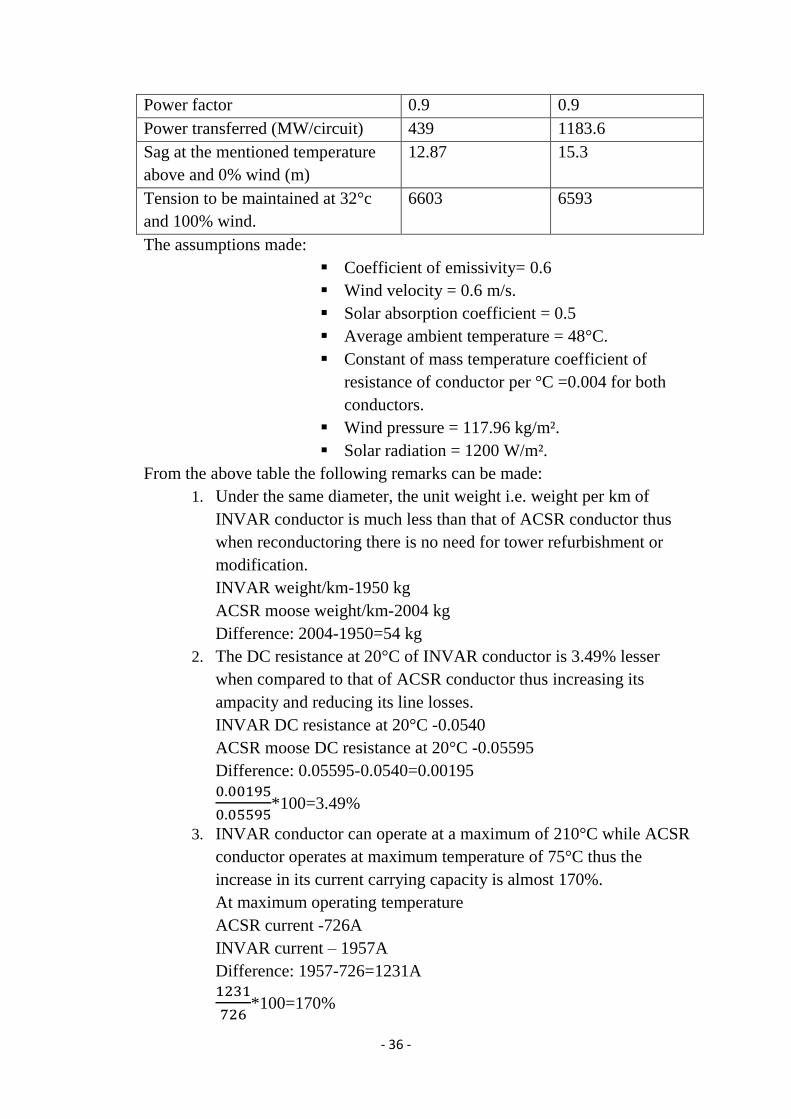
Power factor 0.9 0.9
Power transferred (MW/circuit) 439 1183.6
Sag at the mentioned temperature
above and 0% wind (m)
12.87 15.3
Tension to be maintained at 32°c
and 100% wind.
6603 6593
The assumptions made:
Coefficient of emissivity= 0.6
Wind velocity = 0.6 m/s.
Solar absorption coefficient = 0.5
Average ambient temperature = 48°C.
Constant of mass temperature coefficient of
resistance of conductor per °C =0.004 for both
conductors.
Wind pressure = 117.96 kg/m².
Solar radiation = 1200 W/m².
From the above table the following remarks can be made:
1. Under the same diameter, the unit weight i.e. weight per km of
INVAR conductor is much less than that of ACSR conductor thus
when reconductoring there is no need for tower refurbishment or
modification.
INVAR weight/km-1950 kg
ACSR moose weight/km-2004 kg
Difference: 2004-1950=54 kg
2. The DC resistance at 20°C of INVAR conductor is 3.49% lesser
when compared to that of ACSR conductor thus increasing its
ampacity and reducing its line losses.
INVAR DC resistance at 20°C -0.0540
ACSR moose DC resistance at 20°C -0.05595
Difference: 0.05595-0.0540=0.00195
0.00195
0.05595*100=3.49%
3. INVAR conductor can operate at a maximum of 210°C while ACSR
conductor operates at maximum temperature of 75°C thus the
increase in its current carrying capacity is almost 170%.
At maximum operating temperature
ACSR current -726A
INVAR current – 1957A
Difference: 1957-726=1231A
1231
726*100=170%
Page 37
- 37 -
4. The power transferred in MW by INVAR conductor at its maximum
operating temperature is 169.6% more as compared to that of ACSR
conductor.
Power at maximum operating temperature.
ACSR conductor- 439 MW/cct
INVAR conductor – 1183.6 MW/cct
Difference: 1183.6-439=744.6
744.6
439*100=169.6%
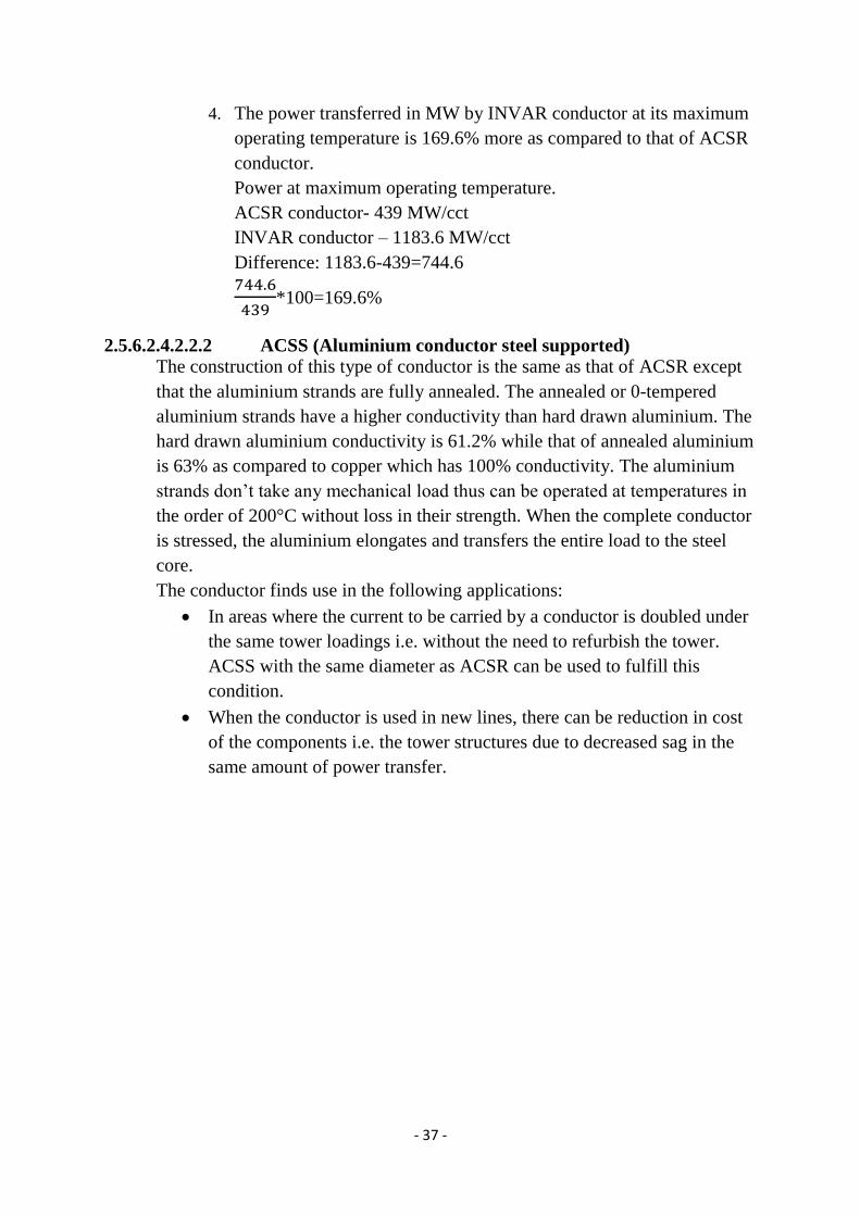
2.5.6.2.4.2.2.2 ACSS (Aluminium conductor steel supported)
The construction of this type of conductor is the same as that of ACSR except
that the aluminium strands are fully annealed. The annealed or 0-tempered
aluminium strands have a higher conductivity than hard drawn aluminium. The
hard drawn aluminium conductivity is 61.2% while that of annealed aluminium
is 63% as compared to copper which has 100% conductivity. The aluminium
strands don’t take any mechanical load thus can be operated at temperatures in
the order of 200°C without loss in their strength. When the complete conductor
is stressed, the aluminium elongates and transfers the entire load to the steel
core.
The conductor finds use in the following applications:
In areas where the current to be carried by a conductor is doubled under
the same tower loadings i.e. without the need to refurbish the tower.
ACSS with the same diameter as ACSR can be used to fulfill this
condition.
When the conductor is used in new lines, there can be reduction in cost
of the components i.e. the tower structures due to decreased sag in the
same amount of power transfer.
Page 38
- 38 -
Figure 8. A figure showing the cross sectional area of a typical ACSS
conductor with trapezoidal aluminium strands.
The numerical data shows the option of using ACSS conductor for the purpose
of reconductoring in place of existing ACSR conductor.
Table 6. The table below shows the technical comparison of ACSR panther
and ACSS lark conductor.
Properties ACSR panther ACSS lark
Conductor Diameter (mm) 21 20.44
Weight (kg/km) 974 925
DC Resistance at 20°C temperature
(ohms/km)
0.139 0.13535
Maximum Operating Temperature
(°C)
75 250
Voltage Level (kV) 132 132
Line length (km) 1 1
Span (m) 325 325
Maintaining same ampacity in ACSS conductor
Calculation temperatures (°C) 75 74.66
Current to be maintained (A) 420 420
AC resistance (ohms/km) 0.1701 0.16516
Line losses (kw/circuit) 90 87.4
Power transferred (MW/circuit) 83.8 83.8
Ampacity at maximum operating temperature in ACSS conductor.
Calculation temperatures (°C) 75 250
Current (A) 420 1180
Page 39
- 39 -
AC resistance (ohms/km) 0.1701 0.26
Line losses (kw/circuit) 90 1086
Power factor 0.9 0.9
Power transferred (MW/circuit) 83.8 235.5
Sag at the mentioned temperature
above and 0% wind (m)
7.244 10.56
Tension to be maintained at 32°c
and 100% wind.
4255 3653.5
The assumptions made:
Coefficient of emissivity= 0.6
Wind velocity = 0.6 m/s.
Solar absorption coefficient = 0.5
Average ambient temperature = 48°C.
Constant of mass temperature coefficient of
resistance of conductor per °C =0.004 for both
conductors.
Wind pressure = 117.96 kg/m².
Solar radiation = 1200 W/m².
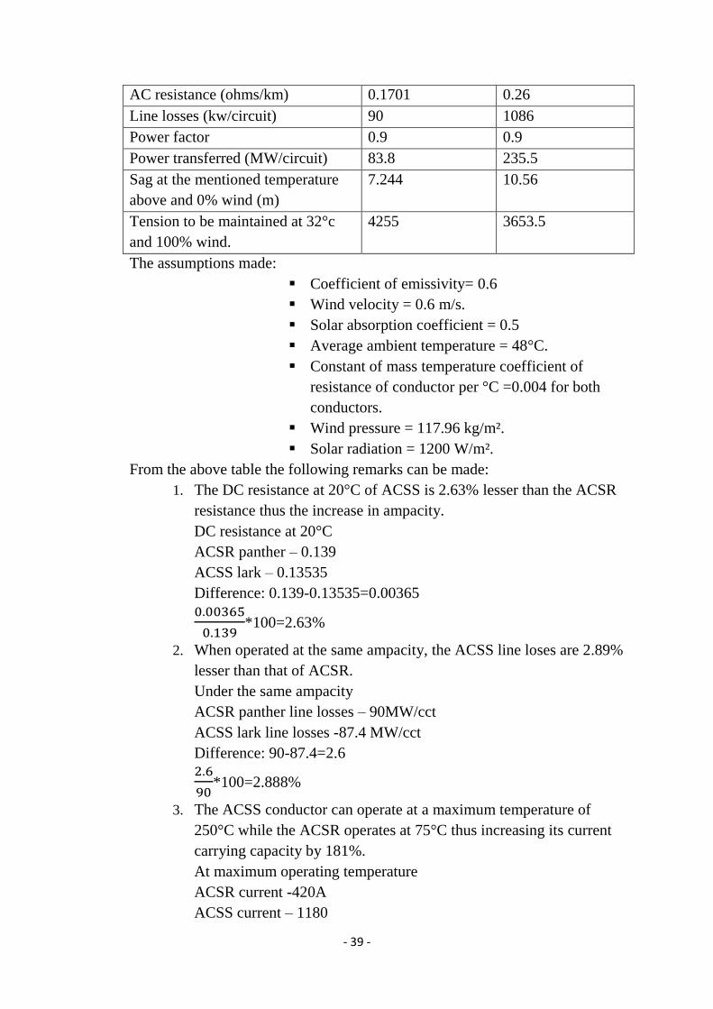
From the above table the following remarks can be made:
1. The DC resistance at 20°C of ACSS is 2.63% lesser than the ACSR
resistance thus the increase in ampacity.
DC resistance at 20°C
ACSR panther – 0.139
ACSS lark – 0.13535
Difference: 0.139-0.13535=0.00365
0.00365
0.139*100=2.63%
2. When operated at the same ampacity, the ACSS line loses are 2.89%
lesser than that of ACSR.
Under the same ampacity
ACSR panther line losses – 90MW/cct
ACSS lark line losses -87.4 MW/cct
Difference: 90-87.4=2.6
2.6
90*100=2.888%
3. The ACSS conductor can operate at a maximum temperature of
250°C while the ACSR operates at 75°C thus increasing its current
carrying capacity by 181%.
At maximum operating temperature
ACSR current -420A
ACSS current – 1180
Page 40
- 40 -
Difference: 1180-420=760A
760
420*100=180.95%
4. The power transferred at maximum conductor operating
temperatures in ACSS is 181% higher than ACSR.
At maximum operating temperature
ACSR power -83.8
ACSS power – 235.5
Difference: 235.5-83.8=151.7
151.7
83.8*100=181%
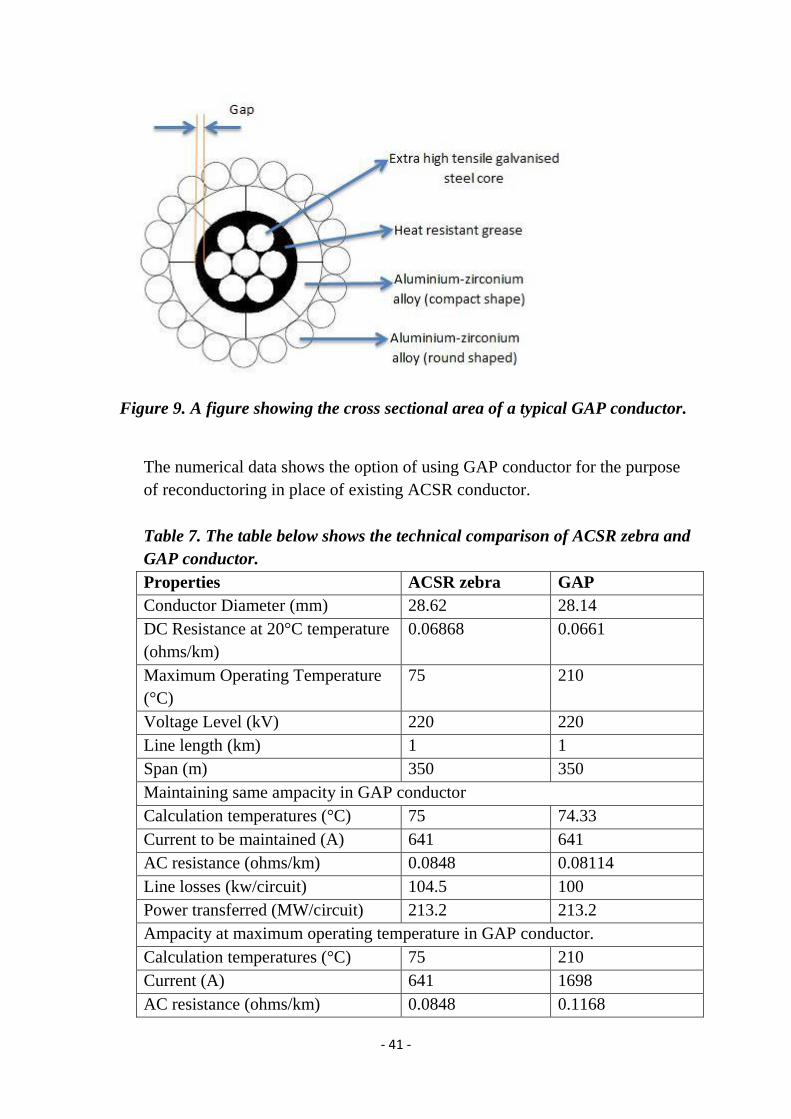
2.5.6.2.4.2.2.3 GAP conductor
This type of conductor involves a small gap maintained in between inner steel core
and outer aluminium-zirconium alloy layers. The steel core is the only one that is
tensioned and it carries the entire mechanical load. The increase in conductors sag
is determined by the coefficient of expansion of the steel core at all temperatures.
The core has low sag when operated at high temperatures in the order of 200°C.
Importance of these conductors
They have ultra-high strength steel core with temperature resistance of up to
250°C
The high temperature grease allows aluminium to move freely over the core
and protect the core from long term corrosion; the grease is resistant to
temperatures of up to 300°C.
The major drawback of these conductors is that the installation process is
complex.
This conductor does not need modification of existing tower structure if it were
to replace ACSR conductor of the same diameter.
Page 41
- 41 -
Figure 9. A figure showing the cross sectional area of a typical GAP conductor.
The numerical data shows the option of using GAP conductor for the purpose
of reconductoring in place of existing ACSR conductor.
Table 7. The table below shows the technical comparison of ACSR zebra and
GAP conductor.
Properties ACSR zebra GAP
Conductor Diameter (mm) 28.62 28.14
DC Resistance at 20°C temperature
(ohms/km)
0.06868 0.0661
Maximum Operating Temperature
(°C)
75 210
Voltage Level (kV) 220 220
Line length (km) 1 1
Span (m) 350 350
Maintaining same ampacity in GAP conductor
Calculation temperatures (°C) 75 74.33
Current to be maintained (A) 641 641
AC resistance (ohms/km) 0.0848 0.08114
Line losses (kw/circuit) 104.5 100
Power transferred (MW/circuit) 213.2 213.2
Ampacity at maximum operating temperature in GAP conductor.
Calculation temperatures (°C) 75 210
Current (A) 641 1698
AC resistance (ohms/km) 0.0848 0.1168
Page 42
- 42 -
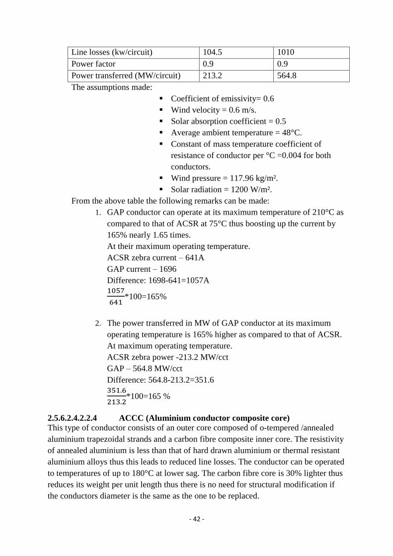
Line losses (kw/circuit) 104.5 1010
Power factor 0.9 0.9
Power transferred (MW/circuit) 213.2 564.8
The assumptions made:
Coefficient of emissivity= 0.6
Wind velocity = 0.6 m/s.
Solar absorption coefficient = 0.5
Average ambient temperature = 48°C.
Constant of mass temperature coefficient of
resistance of conductor per °C =0.004 for both
conductors.
Wind pressure = 117.96 kg/m².
Solar radiation = 1200 W/m².
From the above table the following remarks can be made:
1. GAP conductor can operate at its maximum temperature of 210°C as
compared to that of ACSR at 75°C thus boosting up the current by
165% nearly 1.65 times.
At their maximum operating temperature.
ACSR zebra current – 641A
GAP current – 1696
Difference: 1698-641=1057A
1057
641*100=165%
2. The power transferred in MW of GAP conductor at its maximum
operating temperature is 165% higher as compared to that of ACSR.
At maximum operating temperature.
ACSR zebra power -213.2 MW/cct
GAP – 564.8 MW/cct
Difference: 564.8-213.2=351.6
351.6
213.2*100=165 %
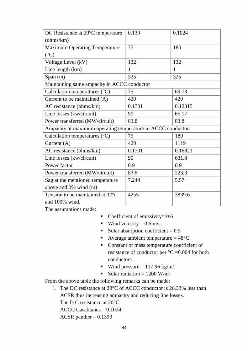
2.5.6.2.4.2.2.4 ACCC (Aluminium conductor composite core)
This type of conductor consists of an outer core composed of o-tempered /annealed
aluminium trapezoidal strands and a carbon fibre composite inner core. The resistivity
of annealed aluminium is less than that of hard drawn aluminium or thermal resistant
aluminium alloys thus this leads to reduced line losses. The conductor can be operated
to temperatures of up to 180°C at lower sag. The carbon fibre core is 30% lighter thus
reduces its weight per unit length thus there is no need for structural modification if
the conductors diameter is the same as the one to be replaced.
Page 43
- 43 -
The carbon fibre core also has a lower coefficient of thermal expansion thus the sag is
low at high operating temperatures hence increased current carrying capacity and no
need to increase the clearance.
Figure 10. A figure showing a typical cross- sectional area of an ACCC conductor.
The ACCC conductor has the following important features:
It has reduced thermal sag when compared to ACSR conductor.
It has reduced line losses when compared to ACSR conductor.
The annealed aluminium strands are in trapezoidal form and this result to an
additional aluminium content which improves the line conductivity while
reducing its losses.
It can reduce the cost of upgrading existing lines or in construction of new lines
due to its greater strength, reduced sag and its increased current carrying
capacity.
It does not corrode, rust or cause electrolysis with aluminium conductor or the
tower components thus it is suitable for polluted and zones near the ocean.
The conductor finds applications in the following areas:
1. Where reduction of line losses is required. Under equal loading
conditions they reduce the line losses by 30-40% compared to other
conductors of the same diameter and weight.
2. Ideal for reconductoring on existing line and upgradation of existing
line. They increase capacity by improving line clearance and reduce
strain on structure thus increasing their life.
The numerical data shows the option of using ACCC conductor for the purpose
of reconductoring in place of existing ACSR conductor.
Table 8. The table below shows the technical comparison of ACSR panther
and ACCC conductor.
Properties ACSR panther ACCC Casablanca
Conductor Diameter (mm) 21 20.5
Weight (kg/km) 974 834.4
Page 44
- 44 -
DC Resistance at 20°C temperature
(ohms/km)
0.139 0.1024
Maximum Operating Temperature
(°C)
75 180
Voltage Level (kV) 132 132
Line length (km) 1 1
Span (m) 325 325
Maintaining same ampacity in ACCC conductor
Calculation temperatures (°C) 75 69.73
Current to be maintained (A) 420 420
AC resistance (ohms/km) 0.1701 0.12315
Line losses (kw/circuit) 90 65.17
Power transferred (MW/circuit) 83.8 83.8
Ampacity at maximum operating temperature in ACCC conductor.
Calculation temperatures (°C) 75 180
Current (A) 420 1119
AC resistance (ohms/km) 0.1701 0.16821
Line losses (kw/circuit) 90 631.8
Power factor 0.9 0.9
Power transferred (MW/circuit) 83.8 223.3
Sag at the mentioned temperature
above and 0% wind (m)
7.244 5.57
Tension to be maintained at 32°c
and 100% wind.
4255 3839.6
The assumptions made:
Coefficient of emissivity= 0.6
Wind velocity = 0.6 m/s.
Solar absorption coefficient = 0.5
Average ambient temperature = 48°C.
Constant of mass temperature coefficient of
resistance of conductor per °C =0.004 for both
conductors.
Wind pressure = 117.96 kg/m².
Solar radiation = 1200 W/m².
From the above table the following remarks can be made:
1. The DC resistance at 20°C of ACCC conductor is 26.33% less than
ACSR thus increasing ampacity and reducing line losses.
The D.C resistance at 20°C
ACCC Casablanca – 0.1024
ACSR panther – 0.1390
Page 45
- 45 -
Difference: 0.1390-0.1024=0.0366
0.0366
0.139*100=26.33
2. By maintaining same ampacity with ACSR conductor, the line losses of
ACCC conductor are 27.59 % lesser.
By maintaining the same ampacity
ACCC losses – 65.17 MW/cct
ACSR losses – 90 MW/cct
Difference: 90-65.17=24.83
24.83
90*100=27.59%
3. ACCC conductor maximum operating temperature is 175°C while
ACSR conductor operates at maximum temperature of 75°C. This
boosts its current carrying capacity by almost 166.43%.
At their maximum operating temperature.
ACCC current-1119A
ACSR current – 420A
Difference: 1119-420=699A
699
420*100=166.43%
4. The power transfer in MW of ACCC conductor at its maximum
operating temperature is 166.45 % higher as compared to that of ACSR
conductor.
At their maximum operating temperature
ACCC power -223.3 MW/cct
ACSR power – 83.8 MW/cct
Difference: 223.3-83.8=139.5 139.5
83.8*100=166.45%
2.5.6.2.4.2.2.5 ACCR (Aluminium conductor composite reinforced)
This type of conductor consists of outer aluminium-zirconium alloy strands and an
inner composite core. The composite core consists of aluminium and aluminium oxide
matrix. The conductor can be operated continuously to temperatures of up to 200°C.
Page 46
- 46 -
Figure 11. A figure showing the cross-sectional area of a typical ACCR conductor.
Table 9. The table below shows the technical comparison of ACSR panther
and ACCC conductor.
properties ACCR 336-T16 ACSR panther
Total diameter (mm) 21 21
Cross-sectional area
(mm²)
198 262
Weight (kg/km) 566 974
Resistance DC @ 20° C
(ohms/km)
0.1614 0.1390
Resistance AC @ 75° C
(ohms/km)
0.2779 0.1701
Voltage (Kv) 132 132
Current (A) 906 509
power (MVA) 207.2 116.3
The assumptions made:
Coefficient of emissivity= 0.6
Wind velocity = 0.6 m/s.
Solar absorption coefficient = 0.5
Average ambient temperature = 48°C.
Constant of mass temperature coefficient of
resistance of conductor per °C =0.004 for both
conductors.
Wind pressure = 117.96 kg/m².
Solar radiation = 1200 W/m².
1. The weight per unit km of ACCR conductor is less by 64 kg when
compared to ACSR conductor thus there is no need for tower
reinforcement when reconductoring
ACCR weight per km-198
ACSR weight per km -262
Page 47
- 47 -
Difference: 262-198=64 kg
2. At the same conductor cross sectional area , the ACCR current carrying
capability is 78% more than that of ACSR
ACCR current-906A
ACSR current- 509A
Difference: 906-509=397
397
509*100=77.99%
3. At the same conductor cross sectional area, the ACCR power carrying
capability is 78.16% more than that of ACSR.
ACCR power-207.2MW
ACSR power- 116.3 MW
Difference: 207.2-116.3=90.9
(90.9)/(116.3)*100= 78.16%
2.6 Conductor hardware and accessories
Uprating of the transmission line to higher current carrying capacity sometimes
involves replacement of associated hardware e.g. towers and conductor accessories
e.g. insulators etc. to cope with the increased current. The hardware is designed in
such a way that they have good heat dissipation characteristics due to the increase in
operating temperatures thus making the operation safe.
Magnetic heating of the clamp as a result of increased current passing through the
conductor also increases which results to an increase in magnetic losses. To solve this
problem ferrous clamp may be replaced with non-ferrous clamps to reduce the
magnetic losses.
Also due to the increase in conductor carrying capacity, the cross-arms distance might
also be increased to cater for insulation. The tower length might also be increased to
cater for clearances effect.
2.7 Conductor selection
Conductor selection can have a significant effect on both the short and long term
economic performance of transmission line projects. Since conductors are one of the
major cost components of a line design, selecting an appropriate conductor type and
size is essential for optimal operating efficiency. Due to this reason, a number of
systematic approaches for conductor selection have been developed.
The choice of appropriate conductor depends on:
Page 48
- 48 -
Electrical load requirements.
The projections in load growth.
Support structure requirements.
Environmental considerations
Set regulations.
Cost of the project.
Some physical and economic factors that affect the choice of conductors are:
Increasing the conductor diameter results to increase in its weight, thus
the wind loading is increased on the support structures hence the need to
reinforce them.
Choosing a conductor with a higher resistance increases the power
losses along the line.
Thus the conductor selection should be based on the total system cost not the unit cost
of the conductor and the economic values it will offer as compared to other
conductors.
From the conductors discussed above, we see that they all have better characteristics
than ACSR conductor. For the purpose of reconductoring, we have to choose the
conductor with outstanding properties among them all.
Figure 12. A graph showing how the increase in temperature affects the cable sag
of different types of conductors.
Page 49
- 49 -
Among all the conductors, the ACCC conductor has lowest sag with increase in
temperature thus this shows that there is no need for structure modification to increase
the clearance when reconductoring if the conductors of the same cross sectional area
are to be used.
Figure 13. A graph showing how increase in temperature affects the current
carrying capability of the different typesof conductors.
Page 50
- 50 -
3 CHAPTER 3.METHODOLOGY
3.1 Introduction
This chapter gives the details on how reconductoring using a conductor of higher
ampacity as the best uprating method of an existing transmission line. The factors to
consider were the right of way hinderances, line losses, need for tower reinforcement
due to increase or decrease in the conductortension and weight, increase in power
transfer capability and ground clearance. The overall project economics was also a
determining factor.
3.2 Formulation
3.2.1 Overhead line rating calculations
Operating current I (A)= SQRT((convection loss-(solar absorption
coefficient*intensity of solar radiation*overall conductor diameter)+(PI*conductor
emissivity*stefans constant*overall conductor diameter)*((conductor temperature rise
above ambient+ambient temperature+273)^4 – (ambient temperature+273)^4)) /a.c
resistance at operating temperature and current)
A.C resistance at operating temperature and current Ra.c (ohms/cm)= direct current
resistance
Intensity of solar radiation Si (watts/cm²)=(intensity of solar radiation/10000)
Overall conductor diameter d(cm)=(diameter(mm)/10)
Convection loss Hc (watts/cm)= IF(wind velocity normal to conductor>= 20,
0.00138*(wind velocity equivalent*conductor diameter)^0.448 *conductor
temperature rise above ambient ,0.00128*(overall conductor diameter)^0.669
*(conductor temperature rise above ambient)^1.233
Conductor operating temperature (°C)=(conductor temperature rise above
ambient+ambient temperature)
Wind velocity equivalent Veq (cm/sec)=wind velocity normal to
conductor*(barometric pressure/760)*(293/(273+ambient temperature)
Barometric pressure b (mm Hg)=(10.33-(altitude above sea level/900)-
0.2357)*1000/13.6
Resistance at operating temperature Rt (Ω/cm)=resistance at 20°C*(1+temperature
coefficient of resistance*(conductor operating temperature-20))
Line rating S (MVA)=number of conductors in bundle*(√3*line voltage*operating
current)/1000000
Page 51
- 51 -
Line losses = phase current² * phase resistance
Calculation constants:
Coefficient of emissivity =0.4
Wind velocity=0.6m/s
Solar absorption coefficient=0.6
Wind pressure=117.96 kg/m²
Solar radiation=1200W/m²
Radiative heat gain=15.096 W/m
Radiative heat loss=11.191 W/m
Convective heat loss=51.252 W/m
Joule heat gain=47.347 W/m
Stefans constant=5.67*10^-12 watts/cm²
Intensity of solar radiation=0.1 watts/cm²
Ambient temperature=35°C
Wind velocity normal to conductor=60 cm/sec
Frequency=50Hz
Temperature coefficient of resistance ρ (k^-1)=0.0036
Page 52
- 52 -
3.2.2 Sag-Tension calculations
Figure 14. A figure showing the conductor sag at two different tower points.
A- Tower A.
B- Tower B.
Deflection is the same as the conductor sag
h- difference in height between tower A and B.
a- Distance from tower A to the conductors lowest point.
b- Distance from tower A to the conductors lowest point.
Ta- conductor tension at tower A.
Tb- conductor tension at tower B.
The ruling span formula is based on the fundamental assumption that the attachments
of the conductor to suspension structures between dead-end structures are flexible
enough to allow for longitudinal movement to equalize the tensions in adjacent spans
to the ruling span tension. If the temperature of a line segment with unequal spans is
raised uniformly, conductor in each span elongates in response to the temperature
change. This elongation increases the sag, thereby decreasing the tension. If the
suspension insulators remained stationary (without any rotation), there would be a
Page 53
- 53 -
tension difference in adjacent spans of different lengths. However, the suspension
clamps displace longitudinally to provide force resolution at each suspension clamp.
For level spans, sag and slack in each suspension span at temperature T call be
calculated from the following parabolic equations.
Sag = Di, t = (w*Si²)/ (8*HR, t) = DR,t * (Si/SR)²
Slack = βi,t = Li,t-Si,t= (8* Di²,t)/(3*Si²) = (Si³*w²)/(24*H²R,t)
Rate of slack = βi,t / Si= (8*D²i,t)/(3*Si²) = (Si²*w²)/(24*H²R,t)
Ruling Span = SR = √ (S³1 + S³2 +. . .+S³n)/(S1 + S2 +. . .+Sn)
The rate of slack at temperature T can be calculated from the following equations:
(Rate of slack)i ,t =βi,t/Si=(Li,t – Si,t)/Si
Where Li,t = Li[1+α(T-Tₒ) +(HR,t-HR)/E*A]
Si,t =Si + (ᶑi - ᶑi-1),t
Substituting for Li,t and Si,t in the rate of slack equation:
Βi,t/Si=(Li*LR,t/(Si*LR)-1-(ᶑi - ᶑi-1),t/Si)
Finally the change in the rate of slack and span length due to a change in temperature
from Tₒ to T can be calculated from the equations below:
Change [βi,t/Si]Tₒ-T = change [βR,t/ SR] Tₒ-T - (ᶑi - ᶑi-1)/Si)
Where D-sag
S-span length
L-conductor length
Β-slack
Tₒ- conductor stringing tension
H- Horizontal conductor tension
w- Conductor unit weight
A- Conductor cross-sectional area
E- Conductor modulus of elasticity
α- Coefficient of thermal expansion
ᶑ - longitudinal horizontal movement of an infinitely flexible suspension clamp.
Subscripts
ₒ- at temperature Tₒ
t- at temperature T
R- Ruling span
Page 54
- 54 -
4 CHAPTER 4: RESULTS AND DISCUSSION
4.1 Results As per the objective of the project, the current conductor ACSR canary 132 properties
were taken from KPLC and its properties compared with other conductors of almost
similar properties to see if reconductoring with a higher a capacity conductor would be
economical. All the calculations were done considering each conductor maximum
operating temperatures. The data was also used to come up with graphs.
Table 10. The table below shows different conductors properties at their maximum
working temperature.
Conductor
type
ACCR
Grosbea
k 636
ACCC
Amsterda
m 380
AAAC
Upas
BSEN5018
2
GAP
310
Goose
INVAR
(ZTACIR
)
ACSS
stilt
ACSR
Canary
132
Conductor
diameter(m
m)
25.5 23.55 24.71 22.6 20.04 20.31 26.12
Conductor
weight
(kg/km)
1079.5 1112.5 997.5 1227 761 1370 1721
D.C
resistance
@20°C
0.0828 0.0754 0.0917 0.0941 0.1580 0.0773 0.0763
4
Conductor
cross
sectional
area (mm²)
385 371.3 362.1 356.2 356 362.5 400
Maximum
operating
temperature
(°C)
200 180 95 200 200 200 75
Maximum
operating
current (A)
1342 1295 767 1217 908 1301 721
A.C
resistance at
75 °C
(Ω/km)
0.1371 0.1195 0.1172 0.1556 0.2607 0.1280 0.0923
Phase 1342.3 1295.4 766.9 1216.6 908.2 1300.9 721.3
Page 55
- 55 -
current (A)
Line- line
voltage(KV)
132 132 132 132 132 132 132
A.C phase
resistance
(Ω)
0.1371 0.1195 0.1172 0.1556 0.2607 0.1280 0.0923
Power S
(MVA)
306.9 296.2 175.3 278.1 207.6 297.4 164.9
Line losses
I²R (KW)
247.023 200.528 68.929 230.30
6
215.032 216.62
0
48.021
Line losses
as a
percentage
of line
power (%)
0.0805 0.0677 0.0393 0.0828 0.1036 0.0728 0.0291
Figure 15. A graph showing the power vs. the cross sectional area relations of
different conductor types.
Page 56
- 56 -
Figure 16. A graph showing the conductor current vs. the conductor weight per km
relations of different conductor types.
Conductor ACCR
Grosbe
ak 636
ACCC
Amsterd
am 380
AAAC
Upas
BSEN501
82
GAP
310
Goose
INVAR
(ZTACI
R)
ACSS
stilt
ACSR
Canary
132
Conductor
diameter
(mm)
25.5 23.55 24.71 22.6 20.04 20.31 26.12
Conductor
area (mm²)
385 383.7 362.1 356.2 356 362.5 400
Conductor
weight per km
1079.5 1112.5 997.5 1227 761 1370 1721
Safety factor 2 2 2 2 2 2 2
Modulus of
elasticity(N/m
m²)
57000 112300 57000 205900 139000 105000 79000
Tensile
strength (N)
113874 122600 106820 107500 89210 96740 82500
Page 57
- 57 -
Stringing
tension (N)
53070.
40
60780.0
3
49753.92 48064.
07
36237.1
8
38496.
03
35194.
07
Ambient
temperature
(°C)
20-30 20-30 20-30 20-30 20-30 20-30 20-30
Operating
temperature
(°C)
200 180 95 200 200 200 75
Radial ice
thickness
(mm)
0 0 0 0 0 0 0
Wind pressure
(N/m²)
400 400 400 400 400 400 400
Table 11. A table of various characteristics of different conductors used for span
and stringing tension calculations.
Figure 17a. A table showing the results of span vs. sag characteristics of different
conductors from sag and tension calculator.
Page 58
- 58 -
Figure 17b. A table showing the results of span vs. sag characteristics of different
conductors from sag and tension calculator.
Figure 18. A graph showing the span vs. sag characteristics of different types of
conductors
Page 59
- 59 -
4.2 Discussion From the four uprating methods discussed earlier, that is:
i. Increasing the conductor rating by changing the thermal rating criteria.
ii. Dynamic environment rating.
iii. Increasing the conductor area.
iv. Reconductoring using conductor of higher ampacity.
We saw that the last option is the one that offers the best method of increasing
ampacity if the long term economic effects were to be put in place. The choice of
conductor selection when reconductoring is also another great factor since tower and
support structure strength has to be considered to ensure no other stress other than the
required is applied to the structure after reconductoring.
From the overhead transmission rating results, it is evident that all the conductors used
for comparison has lower weight per km value than the current ACSR canary
conductor thus this means that there will be no need for structure modification when
reconductoring. It’s caused by the lesser cross sectional area of the other conductors
due to different manufacturing method and the type of material used.
The conductors also have different maximum operating temperatures for ACCR,
GAP, INVAR and ACSS is 200°C while that of ACCC and ACSR is 180°C and 75°C
respectively. ACCR conductor has the highest current capacity at its maximum
operating temperature when compared to the other conductors, 1342 A. it is followed
closely by ACSS and ACCC conductors respectively. These conductors have lesser
diameter than the current ACSR canary conductor. Due to the increase in operating
temperature, when reconductoring using any of the listed conductors above, it would
be necessary to use conductor clamps with a higher heat resistance. The increase in
current leads to an increase in power transfer capability of the transmission line.
ACCR conductor has the highest power carrying capability when operated at its
maximum temperature according to our results, which is 306.9MVA. It is followed
closely by ACSS and ACCC conductor which stands at 297.4 MVA and 296.2 MVA.
ACSR conductor has the lowest power transfer capability among them all. The
conductor line losses also vary according to their carrying capacity and the line phase
resistance at their maximum operating temperatures. The line losses are given by I²R
where I is the current and R the resistance. We can see ACCR has the greatest line
losses but this is a small ratio of its power transfer capability when compared to other
conductors. ACSR has the least line losses but when compared to its power capability,
the ratio is greater than that of the other conductors.
From the power to cross-sectional area graph characteristics, we already saw that
increasing the conductor area is a method used to increase the power transfer
Page 60
- 60 -
capability of a transmission line. However this statement doesn’t translate to the
results we got from the graph. This is because the ampacity of a transmission line
depends on many other factors apart from increasing the cross-sectional area. It’s
evident that ACSR conductor has the largest cross-sectional area among the
conductors while it has the least power transfer capability. The other conductors have
lesser surface area but more power carrying capability than the current ACSR canary
132. Reconductoring using the other conductors will be beneficial due to the increased
capacity with minimal or no tower modification. From the weight per km and
conductor carrying capacity graph, ACSR canary has the greatest weight per km and
carries the least current when compared to the other conductors. This factor is brought
about by ACSR maximum operating temperature. The reduced weight per km means
there will be no or minimal structure reinforcement or modification when
reconductoring thus the other conductors offer a greater advantage when compared to
ACSR. The decreased weight also means that there will be no extra pressure exerted
on the tower structure.
From the span versus sag characteristics graph, ACCC conductor has the lowest sag
with span increase. It is followed closely by AAAC and ACCR conductor
respectively. ACSR has greatest sag –span characteristics, 0.6m at a span of 100m
which was the basic span used for calculations.This leads to use of more materials in
the tower construction to cater for the sag and clearance. This offers another
advantage when reconductoring ACSR using the other conductors since they have
lower sag than the latter. This means there will be no need for structure modification
to cater for sag and clearance thus making it cheaper and faster to reconductor using
the HTLS conductors to increase the power transfer capability.
Page 61
- 61 -
5 CHAPTER 5: CONCLUSION AND RECOMMENDATION
5.1 Conclusion The aim of the experiment was to study the methods of uprating a transmission line
and from the tabular and graphical results we can say that the objective was met. We
see that uprating the existing Dandora to Juja road lines I and II using a high
temperature-low sag conductor (HTLS) such as ACCR would not only increase the
power transfer capability of the lines but would also require less structural
modification. This would lead to great savings when compared to the construction of a
new line. The lesser line losses to power transfer ratio can be of great benefit to the
utility company. Reconductoring process won’t be affected by right of way
hinderances since the tower structure is already in its way. This makes the process not
only efficient method but also a faster way of increasing power transfer capability as
compared to new line construction.
5.2 Recommendation For many years in our country the utility companies has adopted the use of traditional
ACSR conductors, but the technological advancement has led to the introduction of
HTLS conductors. Adoption of this technology in the construction of new
transmission line or reconductoring the existing lines would lead to:
Improved power transfer capability.
Lesser line losses ratio compared to power transfer capability.
Low sag in the HTLS conductors’ causes reduction in tower construction
material since the conductor clearance won’t be a hindering factor.
The increased power carrying capability of HTLS conductor provides room for
future connection due to the rate of increase in population.
Replacement of the current ACSR conductor with ACCR since has the best power
transfer properties among all the other conductors and its sag-span characteristics
lie within the required range. This can lead to all the advantages stated above.
Page 62
- 62 -
6 References
1) The approach to thermal uprating of Transmission line by. S.P.
Hoffmann, A.M. Clark.
2) Methods of increasing the rating of overhead lines by. I. Albizu, A. J.
Mazon, I. Zamora
3) Effective grid utilization by. S. Balser, S. Sankar, R. Miller, T. Curry, A.
Rawlins
4) A review on series compensation and its impact on performance of a
transmission line by Himanshu M. Joshi, Nshant H. Kothari
5) “High temperature conductors” A solution in uprating overhead lines by
R. Criado, I. Zamora, A. J. Mazon
6) Transmission line loadability improvement using FACT device by. R.
H. Besdadiya, C. R. Patel, R. M. Patel
7) Sag and tension calculations for overhead transmission lines at high
temperatures by. Mehran Keshavarzian, Charles H. Priebe
8) Maximizing the ratings of national grids existing transmission line using
high temperature-low sag conductors by M. J. Tunstall, S. P. Hoffmann
9) Statistical approach to thermal rating of overhead lines for power
transmission and distribution by. C. F. Price, R. R. Gibbon
10) Increasing the capacity of overhead lines in the 400KV Spanish
transmission network real time thermal ratings by. F. Soto, D. Alvira, L.
Martin
11) Determination of thermal rating and uprating methods for existing lines
by. R. Stephen, D. Muftic
12) Uprating of transmission capacity in great Riyadh 132 KV transmission
line grid system by adopting low sag and thermal rate up conductor by.
A. Kikuchi, R. Morimoto, K. Mito, Y. Kimura, A. Mikumo
13) Powering up a nation by Essel infraprojects limited. Ramnatt house
community centre, New Delhi.
Page 63
- 63 -
7 Appendix
The overhead transmission line calculator is attached below.
Figure 19a. A figure showing overhead line rating calculator.
Figure 19b. A figure showing overhead line rating calculator.
Page 64
- 64 -
The sag-tension calculator is attached below.
….
Page 66
- 66 -
8 Abbreviations
KPLC- Kenya power and lightning company
IPP - Independent power producers
ROW- Right of Way
FACTS-Flexible alternating current transmission system
NERC- North American electric reliability corporation
HTLS- High temperature Low sag
SIL- Surge impedance loading
AAAC-All aluminium alloy conductor
ACAR-Aluminium conductor alloy reinforced
ACSR-Aluminium conductor steel reinforced
ACCC-Aluminium conductor composite core
ACCR-Aluminium conductor core reinforced
ACSS- Aluminium conductor steel supported
TACSR-Thermal resistant aluminium conductor steel reinforced
SQRT-Square root
Cct-Circuit
MW-Megawatt
KM-Kilometer
KV-Kilovolt
MVA-Megavolt-amperes
A.C. - Alternating current
D.C. - Direct current
Vs. - Versus