UNIVERSITY OF PISA DEPARTMENT OF INFORMATION ENGINEERING Master of Science in Computer Engineering Automatic code generation for security requirements in AUTOSAR based on the Crypto Service Manager September 2016 SUPERVISORS Prof. Gianluca Dini Prof.ssa Cinzia Bernardeschi CANDIDATE Dario Varano
Transcript
UNIVERSITY OF PISA
DEPARTMENT OF INFORMATION ENGINEERING
Master of Science in Computer Engineering
Automatic code generation for security
requirements in AUTOSAR based on the Crypto
Service Manager
September 2016
SUPERVISORS
Prof. Gianluca Dini
Prof.ssa Cinzia Bernardeschi
CANDIDATE
Dario Varano
Abstract
ABSTRACT
The increasing complexity and autonomy of modern vehicles make security
a key issue of the design and development in the automotive industry. A
careful analysis of the security requirements and adequate mechanisms for
ensuring integrity and confidentiality of data are required to guarantee
safety. In the automotive domain, AUTOSAR (AUTomotive Open System
ARchitecture) is the standard de facto. It provides a component-based
system design at different levels of abstraction.
In this thesis a library has been developed to implement the Crypto Service
Manager (CSM) of AUTOSAR. It offers a standardized access to
cryptographic services for applications. The library is implemented in
C-language and supports the modules for MAC generation/verification and
encryption/decryption, according to the standard. In particular, modelling
extensions in AUTOSAR are proposed to address confidentiality and
integrity security constraints at the design stage. Software components are
automatically extended according to security annotations with security
elements (ports and interfaces), used to call the CSM functions.
Nowadays modern cars include technologies for the interconnection with
the outside world, which provides new functionalities for users. These
features help drivers to monitor the status of the vehicles and are helpful
for supporting safety. An example of these functionalities is the vehicle
telematics. It is a method of monitoring a vehicle. It combines a GPS system
with on-board diagnostics to record and map car’s position and speed. If the
3G network is available on the vehicle, it can be used together with the
telematics to send and receive data to a central management system. The
telematics can also include functionalities for live weather, traffic and
parking on the dashboard, apps, voice-activated features and even
Facebook integration. However, with this increased connectivity, also the
potential security threats increase.
The starting point for the security analysis objective of this thesis is the fact
that an adversary already obtained the access to the CAN 1 . It’s a hard
assumption, but it has been shown that such intrusion is possible with
different attacks. Several papers studied car’s vulnerabilities, [1] shows how
1 A Controller Area Network (CAN bus) is a vehicle bus standard designed to allow microcontrollers and devices to communicate with each other in applications without a host computer.
Section 1: Introduction
2
they can be exploited. Authors focused on 3 possible intrusion scenarios,
involving:
Indirect physical access;
Short-range wireless access;
Long-range wireless access.
The first kind of vulnerability involves the On-Board Diagnostic port OBD-II2
and the Entertainment system (Disc, USB and iPod). It’s the easiest attack,
but also the one with the shortest window of opportunity.
The short-range wireless access involves short-range connection, such as
Bluetooth, Remote Keyless Entry, Tire pressure, RFID car keys and Emerging
short-range channels. For all these channels, if a vulnerability exists (as it is)
in the ECU software responsible for parsing channel messages, then an
adversary may compromise the ECU (and, by extension, the entire vehicle)
simply by transmitting a malicious input within the automobile’s vicinity.
Long-range wireless access involves long distance (greater than 1km) digital
access channels, such as Broadcast channel and addressable channels. The
first category comprehends channels which are not specifically directed
towards a given automobile, but can be “tuned into” by receivers
2 The OBD-II standard specifies the type of diagnostic connector and its pinout, the electrical signalling protocols available, and the messaging format. It also provides a candidate list of vehicle parameters to monitor along with how to encode the data for each.
Section 1: Introduction
3
on-demand. In addition, attackers may command multiple receivers at once
and don’t require to obtain precise addressing for their victims. In general,
these channels are implemented in automobile’s media system (radio, CD
player, satellite receiver) which frequently provides access via internal
automotive networks to other key automotive ECUs. The second category
of channels are perhaps the most important part of long-range wireless
attack surface, as they are exposed by the remote telematics system that
provide continuous connectivity via cellular voice and data networks. The
features which these channels support are crash reporting, diagnostics (e.g.
early alert of mechanical issues), anti-theft (remote track and disable) and
convenience (weather and driving directions). These cellular channels offer
many advantages for attackers, they can be accessed over arbitrary distance
in a largely anonymous fashion and are individually addressed [1].
This thesis is conceptually divided into 4 parts. The first one explores
AUTOSAR, the actual standard for the modelling and developing of vehicle’s
applications. The second part shows a simple use case, where all the
concepts stated in the first part are used and an analysis of the possible
threats which may affect the system is reported. The use case analyzed is
the Front Light Management System [2]. In particular, connections have
been inspected. After the modelling phase of the system, according to the
current standard, a safety and security analysis has been performed. The
Section 1: Introduction
4
next step performed has been the identification of possible threats
following the standard S.T.R.I.D.E. threat category [3], starting from that, a
possible attack tree has been designed. The risk analysis performed on the
attack tree follows the statement of the European Project EVITA [4], which
suggests a way to estimate the attack’s potential of the possible threats over
the attack tree designed. The third part of the thesis has the aim of
inspecting how AUTOSAR allows users to include security during the
modelling phase. This can be done through an AUTOSAR service called
Crypto Service Manager, which provides cryptographic functionalities to
applications. It will be discussed how the official method is complex and
error-prone. An extension of the security modelling concepts currently
available in AUTOSAR is proposed. Developers specify integrity and
confidentiality security requirements by adding security tags in the
description field of AUTOSAR software components. A tool for the
automatic generation of security elements from the security annotations
will be presented. The last part of the thesis proposes a possible
implementation of the AUTOSAR Crypto Service Manager, in particular the
Mac Interface, the Symmetrical Block Interface and the Symmetrical
Interface have been developed. The implementation proposed follows the
AUTOSAR standard.
Section 1: Introduction
5
This work was conducted as part of the European project SAFURE [5] (Safety
And Security By Design For Interconnected Mixed-Critical CyberPhysical
Systems). The project targets the design of cyber-physical systems by
implementing a methodology that ensures safety and security "by
construction". The goals of the SAFURE project are the following:
to implement a holistic approach to safety and security of embedded
dependable systems, preventing and detecting potential attacks;
to empower designers and developers with analysis methods,
development tools and execution capabilities that jointly consider
security and safety;
to set the ground for the development of SAFURE-compliant
mixed-critical embedded products.
Section 2: AUTOSAR
6
2 AUTOSAR
Modern cars have up to 80 different ECUs 3 interacting with each other
through a complex wired network. ECUs are made by different
manufacturers and each ECU has a software embedded in it, which provides
a specific functionality. For these reasons, software of an ECU could not
work on a different manufacturers’ ECU, this means that software is not
portable. Additionally, the increasing number of ECUs (in some top of the
line models there are more than 100 such devices) and the increasing
complexity of embedded software, increase the complexity of the car’s
software development process, both in time-to-market and in the final cost.
Because of this, AUTOSAR (AUTomotive Open System ARchitecture) has
been founded.
AUTOSAR is a worldwide development partnership of automotive
interested parties founded in 2003. Some of AUTOSAR partners are BMW,
Bosch, Continental, General Motors, Volkswagen, Ford, Toyota and Renault.
It pursues the objective of creating and establishing an open and
standardized software architecture for automotive electronic control units.
3 ECU (Electronic Control Unit): is a generic term for any embedded system that controls one or more of the electrical system or subsystems in a motor vehicle (e.g. Door Control Unit, Human Machine Interface, Telematics Control Unit, and so on)
Section 2: AUTOSAR
7
2.1 AUTOSAR ARCHITECTURE
As shown in Figure 1, AUTOSAR has a three-layer architecture [6]:
1. Application layer;
2. Runtime Environment (RTE) layer;
3. Basic Software (BSW) layer.
The application layer contains the Software Components (SWCs), pieces of
information providing specific functionalities. The RTE layer is the
middleware, which provides a communication abstraction for SWCs. BSW
provides basic services and basic software modules to SWCs.
SWCs can’t access to BSW directly, all communications, both between SWC-
SWC and SWC-BSW, have to pass through the RTE. Because of the RTE
abstraction layer, SWCs can be developed independently of the underlying
hardware, so software providing specific functionalities may be reused on
vehicle having ECU made by different vendors.
Section 2: AUTOSAR
8
Figure 1: AUTOSAR: three-layer Architecture
2.1.1 Application Layer
In AUTOSAR, “application” software [7] is conceptually located above the
AUTOSAR RTE and consists of:
AUTOSAR application software-components, that are ECU and
location independent;
AUTOSAR sensor-actuator components, that are dependent on ECU
hardware and thus not readily relocatable for reasons of
performance/efficiency.
Section 2: AUTOSAR
9
Due to the RTE Abstraction Layer, they can be implemented independently
of the underlying hardware. Software components encapsulate the
implementation of their functionality and behavior and they expose well-
defined connection points, called PortPrototypes, which are the only mean
through which they can communicate with the outside world. Figure 2
shows a graphical representation of a SWC in AUTOSAR.
Figure 2: AUTOSAR: Graphical rapresentation of a SWC
The main communication paradigms between software components are
client/server, for operation-based communication, and sender/receiver, for
data-based communication:
Sender-receiver communication involves the transmission and
reception of signals consisting of atomic data elements that are sent
by one component and received by one or more components. A
Section 2: AUTOSAR
10
sender-receiver interface can contain multiple data elements.
Sender-receiver communication is one-way: any reply sent by the
receiver is sent as a separate sender-receiver communication;
Client-server communication involves, the client which is the require
(or user) of a service and the server that provides the service. The
client initiates the communication, requesting that the server
performs a service, transferring a parameter set if necessary. The
server, in the form of the RTE, waits for incoming communication
requests from a client, performs the requested service and
dispatches a response to the client’s request. The invocation of a
server is performed by the RTE itself when a request is made by a
client. The invocation occurs synchronously with respect to the RTE
(typically via a function call) however the client’s invocation can be
either synchronous (wait for server to complete) or asynchronous
with respect to the server.
2.1.2 RTE Layer
The RTE [6] provides the infrastructure services that enable communication
to occur between AUTOSAR software components as well as acting as the
means by which software components access basic software modules
including the Operating System (OS) and communication service. As already
Section 2: AUTOSAR
11
stated, the RTE make software components independent from the mapping
to a specific ECU.
2.1.3 BSW Layer
The BSW Layer is divided into three sublayers [8], this approach allows for a
better reuse of the more abstract parts of the description:
1. The upper layer, the BswModuleDescription, contains the
specification of all the provided and required interfaces including the
dependencies to other modules;
2. The middle layer, the BswInternalBehavior, contains a model of some
basic activity inside the module. This model defines the requirements
of the module for the configuration of the OS and the BSW Scheduler.
Note that it is restricted only to the scheduling behavior here and
does not describe the algorithmic behavior of the module;
3. The bottom layer, the BswImplementation contains information on
the individual code.
2.2 AUTOSAR TOOL
AUTOSAR tool refers to all tools that support the tasks of creation,
modification and interpretation of AUTOSAR models. In the development
process of an AUTOSAR compliant system, many tools (coming from
different vendors) may be involved. The data exchanged between these
Section 2: AUTOSAR
12
different tools need to agree on a common understanding about the
wording and the semantics. AUTOSAR formally defines the structure and
semantics of data by means of Unified Modeling Language (UML) class
diagrams. In addition, AUTOSAR has chosen eXtensible Markup Language
(XML) as a language for exchange of data between different AUTOSAR tools
[9]. Therefore, an AUTOSAR system can be described in AUTOSAR XML
(ARXML).
2.3 AUTOSAR META-MODELS
2.3.1 Software components
Software Component (SWC) are one of the most important architectural
elements of the AUTOSAR meta-model. They represent piece of software
which provide specific functionalities and they provide and/or require
interfaces and are connected to each other to fulfill architectural
responsibilities.
Section 2: AUTOSAR
13
Figure 3: AUTOSAR: SWC metamodel
Figure 3 shows the meta-model for SWCs:
• ApplicationSwComponentType and
SensorActuatorSwComponentType represent, respectively, the
application software and the software running on sensor/actuator
(there are other types of SwComponentType which are not shown in
figure, because they are not interesting for our purposes);
• CompositionSwComponentType is used to aggregate two or more
SwComponentPrototype (every one of which is typed by a
SwComponentType). This can be useful to represents a system
composed by two or more software components and to see how they
are connected between each other;
Section 2: AUTOSAR
14
• SwComponentPrototype represents an instance of a
SwComponentType (ApplicationSwComponentType,
SensorActuatorSwComponentType or other not shown in figure)
within a CompositionSwComponentType. Every
SwComponentPrototype is typed by one SwComponentType.
2.3.2 Ports
Software components can communicate between each other, only by
means of their PortPrototype. Every port is typed by one interface. Two
ports can be connected only if they are typed by the same interface.
Figure 4: AUTOSAR: Port meta-model
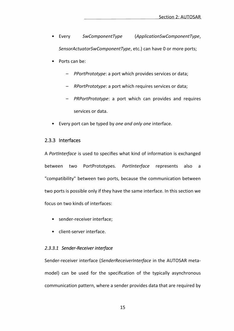
Figure 4 shows the meta-model for ports and their relations with software
components:
Section 2: AUTOSAR
15
• Every SwComponentType (ApplicationSwComponentType,
SensorActuatorSwComponentType, etc.) can have 0 or more ports;
• Ports can be:
– PPortPrototype: a port which provides services or data;
– RPortPrototype: a port which requires services or data;
– PRPortPrototype: a port which can provides and requires
services or data.
• Every port can be typed by one and only one interface.
2.3.3 Interfaces
A PortInterface is used to specifies what kind of information is exchanged
between two PortPrototypes. PortInterface represents also a
"compatibility" between two ports, because the communication between
two ports is possible only if they have the same interface. In this section we
focus on two kinds of interfaces:
• sender-receiver interface;
• client-server interface.
2.3.3.1 Sender-Receiver interface
Sender-receiver interface (SenderReceiverInterface in the AUTOSAR meta-
model) can be used for the specification of the typically asynchronous
communication pattern, where a sender provides data that are required by
Section 2: AUTOSAR
16
one or more receivers. A PortPrototypes typed by a SenderReceiverInterface
may be connected to establish a 1..n (i.e. one sender, multiple receivers)
communication relationship. SenderReceiverInterface is also used to
specifies the data elements sent and received over the ports which are
typed by that interface.
The meta-model for SenderReceiverInterface is shown in Figure 3.7.
Internal behavior (SwcInternalBehavior in the AUTOSAR meta-model)
provides means for formally defining the behavior of a software
component. In other words, it describes the relevant aspects of the
software-component with respect to the Runtime Environment (RTE), i.e.
the runnable entities (which are the smallest code-fragments that are
provided by a software component) and the RTE events they respond to.
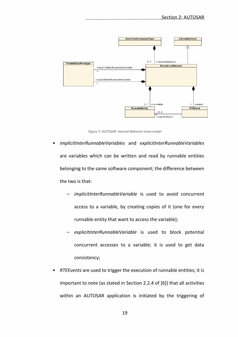
The meta-model for internal behavior is shown in Figure 7:
• SwcInternalBehavior can contain one or more RunnableEntity;
Section 2: AUTOSAR
19
Figure 7: AUTOSAR: Internal Behavior meta-model
• implicitInterRunnableVariables and explicitInterRunnableVariables
are variables which can be written and read by runnable entities
belonging to the same software component; the difference between
the two is that:
– implicitInterRunnableVariable is used to avoid concurrent
access to a variable, by creating copies of it (one for every
runnable entity that want to access the variable);
– explicitInterRunnableVariable is used to block potential
concurrent accesses to a variable; it is used to get data
consistency;
• RTEEvents are used to trigger the execution of runnable entities; it is
important to note (as stated in Section 2.2.4 of [6]) that all activities
within an AUTOSAR application is initiated by the triggering of
Section 2: AUTOSAR
20
runnable entities by the RTE as a result of RTE events. Relation
between a runnable entity and an RTEEvent is specified by means of
startOnEvent reference (as shown in figure); this means that when
an RTEEvent occurs, it is the responsibility of the RTE to trigger the
execution of the corresponding runnable entity.
One of the most common RTE events is the TimingEvent: a periodic
event whose period can be specified (in seconds) in the period
attribute of the TimingEvent class. The complete list of events is
written in section 4.2.2.4 of [6].
2.3.4 AUTOSAR Services
AUTOSAR Services can be seen as a hybrid concept between Basic Software
Modules and Software components. Software components that requires
AUTOSAR services use standardized AUTOSAR interfaces to communicate
with them.
The dependency of a software component from an AUTOSAR service is
modeled by adding provided or required ports (hereinafter referred to as
’service ports’) to the software component. The interface for these ports
needs to be one of the standardized service interfaces defined in the
AUTOSAR documentation, and the attribute isService of the interface must
be set to true. Furthermore, the internal behavior of the software
Section 2: AUTOSAR
21
component shall contain a SwcServiceDepencency, which is used to add
more information about the required service.
Figure 8: AUTOSAR: Service Dependency meta-model
The meta-model of the SwcServiceDepencency is shown in Figure 8, a
description for each element is the following:
• SwcServiceDepencency is used to associate ports, port groups and (in
special cases) data defined for a software component to a given
ServiceNeeds element;
• ServiceNeeds are used to provide detailed information about what a
software component expects from the AUTOSAR service. For
instance, CryptoServiceNeeds can be used to specify a maximum
length for the key used in cryptographic services;
Section 2: AUTOSAR
22
• RoleBasedPortAssignment is used to specify an assignment of a role
to a particular service port of a software component. With this
assignment, the role of the service port can be mapped to a specific
ServiceNeeds element. The attribute portPrototype of this class, is
used to refer a service port of the software component.
From ServiceNeeds can be derived other classes, shown in Figure 9, which
will not been considered, as they are not useful for our purpose.
Figure 9: AUTOSAR: ServiceNeeds meta-model
Section 3: Cyber Security: a use case
23
3 CYBER SECURITY: A USE CASE
3.1 SYSTEM DESCRIPTION
The system which this work will analyze is the Front Light Manager (based
on the system defined in [2]). It’s in charge of managing the low beams
feature of a car. All other light functionalities like parking orientation light,
fog lights, etc. are excluded. A graphical description of the system is shown
in Figure 10.
Figure 10: Front Light Manager: System overview
The general purpose of the low beams system is to illuminate the roadway
in the dark. The low beams are turned on by the user through the Light
Switch, if the Ignition Key is ON. System status (malfunctions included) shall
Section 3: Cyber Security: a use case
24
be reported to the driver through the Human Machine Interface (HMI in
Figure 10). In case of low beams malfunctions the Onboard Computer shall
signal the closest repair center to the driver. The functioning rules for the
Front Light Management (FLM) are the following:
1. Detection of a low beams request:
The FLM shall evaluate the Ignition Key position;
The FLM shall read the Light Switch position;
2. Evaluate the low beams light request:
The FLM shall evaluate the Light Switch status;
The FLM shall create a switch event (ON) if the Light Switch
status changes from OFF to ON;
The FLM shall create a switch event (OFF) if the Light Switch
status changes from ON to OFF;
3. Control the low beams lights:
The FLM shall activate the low beams light if the Ignition Key
position is ON and a Light Switch event is detected;
The FLM shall deactivate the low beams light if the Ignition
Key position is OFF, or a Light Switch event (OFF) is detected;
4. Monitoring the low beams light functioning:
The FLM shall supervise the low beams lights;
The FLM shall report a malfunctioning of the low beams lights;
Section 3: Cyber Security: a use case
25
The FLM shall display the low beams lights status to the user
by means of the HMI; in case of low beams malfunctioning,
FLM shall display the closest repair center through the On-
board Computer (OBC);
5. Activation of the daytime running lights:
The FLM shall activate the daytime running lights in case of a
low beams lights malfunctioning.
A communication focused view of the technical interfacing is shown in
Figure 11.
Figure 11: Front Light Management: communication focused view
3.2 ASSUMPTIONS AND LIMITATIONS
As starting point, the following assumptions are defined:
1. Implementation of Front Light Management software on one ECU;
Section 3: Cyber Security: a use case
26
2. Activation of light via switch which provides one output that is a
digital I/O;
3. Emergency light functionality is provided by hardware and not
intended to use AUTOSAR software parts;
4. All memory (volatile and non-volatile) is protected against reversible
transient faults. It is assumed that mechanisms like ECC are available;
5. Hardware means for memory partitioning are available;
6. The analysis of failure modes of the micro-controller is performed
and safety measures are defined and implemented;
7. Physical cyber-attacks are not taken into account, as they are a
special case and they have to be treated in different ways.
Additionally, subsequent constraints are defined:
1. Assuming that the ECU is working as required:
1.1. The ECU is waking up; running and going to sleep correctly;
1.2. The necessary communication network is available, up and running
correctly;
1.3. The necessary Basic Software Modules are triggered as required.
2. Failures in the board wiring system, battery or power supply are not
considered. Even though the battery is external to the FLM, its failures
will directly affect the FLM and any other vehicle’s electronics systems;
3. A startup test of the bulbs is assumed to be in place;
Section 3: Cyber Security: a use case
27
4. The light switch signal is already filtered/de-bounced. Furthermore, it is
assumed that the signal is provided in an adequate quality to match
requirements of ISO 2626.
3.3 WARNING AND DEGRADATION CONCEPT
For the low beams lights the following 2-step degradation concept shall be
implemented:
Normal Mode:
• The system work as described in 3.1.
Degraded Mode Step 1 - loss of one low beams:
• The second low beams still fulfills its function;
• A warning shall be provided to the driver (by means of HMI),
indicating partial loss of low beams, while low beams is requested
but not successfully activated (fault detected);
• The Onboard Computer shall provide the closest repair center.
Degraded Mode Step 2 - loss of both low beams4:
4 Additional driver assistance functions could be activated in this mode to assist the driver, but this is not part of this example.
Section 3: Cyber Security: a use case
28
• Day time running lights shall be activated, whenever low beams is
requested but not successfully activated (fault detected)5;
• A warning shall be provided to the driver (by means of HMI),
indicating loss of low beams and activation of daytime running lights,
while low beams is requested.
• The OBC shall provide the closest repair center.
3.4 SYSTEM MODELING
3.4.1 Modeling Tool
The tool used to model the system is IBM Rational Rhapsody Developer. It’s
a visual development environment for embedded, real time or technical
application software development based on the Unified Modeling Language
(UML). It helps to improve productivity throughout the embedded software
development lifecycle—from requirements capture to implementation, test
and deployment. In our purpose I used it to model the system, starting from
requirements and system’s description. The tool is used also within the
project SAFURE6 [5] and by Magneti Marelli7 [10].
5 This kind of usage of day time running light as fallback is just used as an example to demonstrate a degraded function. 6 SAFURE (Safety And Security By Design For Interconnected Mixed-Critical Cyber-Physical Systems): the project targets the design of cyber-physical systems by implementing a methodology that ensures safety and security "by construction". 7 Magneti Marelli is an international Group committed to the design and production of hi-tech systems and components for the automotive sector
Section 3: Cyber Security: a use case
29
3.4.2 System’s Components Definition
The system can be modeled using the following Software Components
(SWC):
• Sensor SWC (Light Switch);
• Sensor SWC (Ignition Key);
• Application SWC (Light Request);
• Application SWC (Front Light Management, FLM);
• Actuator SWC (Headlights);
• Application SWC (HMI);
• Application SWC (Onboard Computer).
Figure 12 shows the interactions between components. Communication
flow between components is shown in Figure 13.
Figure 12: Front Light Management: system Software Components overview
Section 3: Cyber Security: a use case
30
Figure 13: Front Light Management: sequence diagram
3.4.3 Software Components Behavior
• Light Switch: it waits for an incoming request from Light Request and
provide the switch status as a response;
• Ignition Key: it waits for an incoming request from Light Request and
provide the Ignition Key status;
• Light Request: it waits for an incoming request from Front Light
Management and asks Light Switch and Ignition Key for their status,
it waits for their reply and it provides this information to the Front
Light Management.
• Front Light Management:
1. it asks to the Light Request for Light Switch and Ignition Key
status;
Section 3: Cyber Security: a use case
31
2. it processes the status information obtained in the previous step
and reacts by activating/deactivating the low beams using the
Headlights actuator;
3. it sends a notification the HMI.
If one or both low beams lights fails, a notification is sent to the HMI
and to On Board Computer. In addition, if both low beams fail, Front
Light Management sends to the Headlights actuator the command to
activate the daytime running lights.
• Headlights: it applies the commands received from the Front Light
Management.
• HMI: it shows the low beams status to the user (e.g. green light if low
beams are ON and working, red light in case of low beams
malfunction).
• OBC: in case of malfunction of one or both the low beams, On Board
Computer shows the closest repair center location to the user.
3.4.4 ECU Mapping
The system shall be mapped as shown in Figure 14. The Front Light
Management and Light Request elements shall reside on the same ECU. The
technical interfacing of system elements with Front Light Management ECU
is assumed as shown in Table 1.
Section 3: Cyber Security: a use case
32
Figure 14: Front Light Manager: Components ECU mapping
System Element Interface of FLM ECU
Light Switch Position DIO
Ignition Key Position CAN Interface
Headlight PWM
HMI CAN Interface
On-Board Computer CAN Interface
Table 1: Interfaces of FLM ECU
3.4.5 Communication failure handling
The AUTOSAR standard provides a mechanism to detect and handle, at
runtime, communication failures within a communication link. The provided
mechanism is the End-to-End (E2E) protection [11]. The AUTOSAR E2E
protection can be used to protect data element within a sender-receiver
communication. It is not applicable to client-server communication
paradigm. By applying the E2E protection, basically the sender adds
protection information (such as CRC, sequence counter) to the data and the
Section 3: Cyber Security: a use case
33
receiver evaluates the received message and indicates the result to the
application. The E2E protection has the following characteristics:
1. it protects the safety-related data elements to be sent over the RTE
by attaching control data;
2. it verifies the safety-related data elements received from the RTE
using this control data;
3. it indicates that received safety-related data elements faulty, which
then has to be handled by the receiver Software Components.
Regardless where E2E is executed, the E2E Protection is for data elements.
A data element is either completely E2E-protected, or it is not protected. It
is not possible to protect a part of it. An appropriate usage of the E2E Library
alone is not sufficient to achieve a safe E2E communication according to ASIL
D (the highest ASIL value) requirements. Solely the user is responsible to
demonstrate that the selected profile provides sufficient error detection
capabilities for the considered network.
E2E communication protection aims to detect and mitigate the causes for
or effects of communication faults arising from:
1. (systematic) software faults;
2. (random) hardware faults;
Section 3: Cyber Security: a use case
34
3. transient faults due to external influences (repetition of information,
loss or delay of information, masquerading, corruption of
information and so on).
3.4.6 IBM Rational Rhapsody Model
Software Components have been implemented using Application SW
Component (FLM and Light Request) and Sensor-Actuator SW Component
(HMI, OBC, Headlight, IgnitionKey and LightSwitch).
All the interfaces defined are Sender-Receiver, as components need to
exchange data. In order to do that, communicating ports must have the
same interfaces.
At Software Component level, all the components are interconnected using
a Virtual Functional Bus (VfB), which acts as a communications matrix
connecting I/O units and Software Components.
The model obtained by modeling the use case using IBM Rational Rhapsody
is shown in Figure 15.
Section 3: Cyber Security: a use case
35
Figure 15: Front Light Manager: model from IBM Rational Rhapsody
3.4.7 Security problem
Looking at the model presented in the previous section, it is clear that no
security is modeled (or requested). At Software Component level there is no
easy way to request security services.
Security nowadays is a fundamental problem when designing a service.
Networks inside cars may be victims of cyber-attacks, like classical computer
networks. Before defining which security services are needed, it’s important
to define which cyber-attacks threaten the use case.
In the next section an analysis of the possible threats will be done, which is
the starting point to provide a solution to this security lack.
Section 3: Cyber Security: a use case
36
3.5 SAFETY AND SECURITY CONCEPTS
The following subsection outlines the safety analysis on vehicle level and its
result typically created by the OEM and partially provided to a supplier.
3.5.1 Hazard Analysis and Risks Assessment
Hazard H1: Total loss of low beams (ASIL B).
This hazard potentially could cause the driver to lose control of the vehicle,
leave the road and collide with environmental parts.
Exceptions and Boundary Conditions to H1:
• The loss of low beams is only to be seen as a risk in case of bad
viewing conditions (night, fog, etc.).
• The loss of low beams on a curvy, unlighted rural road is evaluated
as a most critical situation.
• The loss of only one low beams is not considered to be directly
leading to a hazardous situation. However, it is a latent fault and will
be included in the concept advisement.
ASIL: The ASIL B rating is based on the severity rate the exposure rate and
the controllability identified during hazard analysis and risk assessment.
Safety Goal SG01: Prevent total loss of low beams
Safe State: Low beams activated
Section 3: Cyber Security: a use case
37
Hazard H2: Lose control of the system due to an external intrusion in the
system (ASIL B).
An intruder who takes control of the system can potentially alter the low
beams status and simulate a low beams malfunction. These situations could
cause the driver to lose control of the vehicle or force the driver to stop in
one specific repair center.
Exceptions and Boundary Conditions to H2:
• In case of low beams malfunction (real or caused by an external
entity), the driver not necessarily stop to closest repair center.
• A low beams malfunction, if it happens during night, may force the
driver to stop in a dangerous area.
Others exceptions and boundary conditions expressed for H1 applies also to
H2.
Security Goal SG02: Prevent an external (not authorized) entity to access to
the system.
Secure State: An external (not authorized) entity is not able to access and
take control of the system.
Note: Additional hazards could be assumed. However, to limit our example,
H1 and H2 are assumed to be the relevant hazards.
Section 3: Cyber Security: a use case
38
3.5.2 Relevant Failure Modes
The safety goal SG01 can be violated through one or more of the following
malfunctions (MF):
• MF01: Failure of the detection of the turn-on/ turn-off conditions of
lights;
• MF02: Failure of the evaluation and implementation of the light
request function which is used to turn lights on;
• MF03: Failure of the activated lights.
The security goal SG02 can be violated through one or more of the following
malfunctions:
• MF04: Malicious injection of fake messages over the CAN8 bus;
• MF05: Malicious injection of code into FLM ECU, HMI or OBC.
3.5.3 Functional Safety and Security Requirements
3.5.3.1 FunSafReq01
FLM shall detect any valid turn on condition of low beams correctly. (ASIL B)
Relates to MF01: Low beams are not activated after a “valid LB lights ON”
request.
8 A Controller Area Network (CAN bus): a vehicle bus standard designed to allow microcontrollers and devices to communicate with each other in applications without a host computer. It is a message-based protocol, designed originally for multiplex electrical wiring within automobiles, but is also used in many other contexts.
Section 3: Cyber Security: a use case
39
3.5.3.2 FunSafReq02
FLM shall verify the validity for any low beams lights request received and
activate or deactivate the low beams accordingly. (ASIL B) Relates to MF02:
Switching lights off without receiving a “valid LB lights OFF” request.
3.5.3.3 FunSafReq03
FLM shall detect failures of the activated low beams and signal malfunctions
to the driver. (ASIL B) Relates to MF03: Failure of the activated lights.
3.5.3.4 FunSecReq01
FLM shall verify the authenticity of received CAN messages. Relates to
MF04.
3.5.3.5 FunSecReq02
The ECU’s software shall be developed according to software development
standards like MISRA C [12] and CERT [13]. Relates to MF05.
3.5.4 Technical Safety Requirements
3.5.4.1.1 SysSafReq01
The CAN connected Body Controller shall signal Ignition Key clamp 15 (CL15)
status via CAN bus message.
Section 3: Cyber Security: a use case
40
3.5.4.1.2 SysSafReq02
The light switch shall signal the state of the switch via digital HW line.
HW_LB_OFF (0=0V if lights on are requested, 1=5V if lights off are
requested). (ASIL B)
3.5.4.1.3 SysSafReq03
Failures within the light switch shall lead to the digital HW line. HW_LB_OFF
set to 0. (ASIL B)
3.5.4.1.4 SysSafReq04
FLM ECU shall ensure that the limits (like voltage and PWM) to power the
LB bulbs are kept, while FLM ECU detects that the condition for powering
the bulbs is fulfilled (as defined as part of nominal function). (ASIL B)
3.5.4.1.5 SysSafReq05
While CL15ON==1, FLM ECU shall switch the light off only if HW_LB_OFF ==1
condition is true continuously for 20ms 9 (CAN message: CL15_01; CAN
signal: CL15ON Boolean, ‘1’ if clamp 15 is set to on, ‘0’ if clamp 15 is set to
off). (ASIL B):
9 The timing condition to wait for a stable condition for some milliseconds is included to debounce the signal value. The particular value of 20ms is taken as experts’ experience. Another value could be used instead, as well.
Section 3: Cyber Security: a use case
41
3.5.4.1.6 SysSafReq06
FLM ECU shall detect circuit failures (bulbs, fuses, wiring-oc/sc) and signal
them via CAN. (ASIL B)
3.5.4.1.7 SysSafReq07
FLM ECU shall activate both daytime running lights (DRL) if a failure of both
LB bulbs is detected continuously for 200ms. (ASIL B) Note: The FTT budget
is allocated the following way: 200ms failure detection time + conservative
200ms time interval until halogen bulb reaches full intensity (failure
reaction) + 100ms buffer = 500ms.
3.5.4.1.8 SysSafReq08
FLM ECU shall use independent circuits to power left and right bulbs such
that no single fault can cause a total loss of low beams. (ASIL B)
3.5.4.1.9 SysSafReq09
HMI shall display bulb outage information according to the signal LBFailure
received via CAN. (ASIL A)
3.5.4.1.10 SysSafReq10
The data transmission via CAN between sender and receiver must be
ensured for CAN message: CL15_01 CAN signal: CL15ON Boolean, (‘1’ if
clamp 15 is set to on, ‘0’ if clamp 15 is set to off). (ASIL B)
Section 3: Cyber Security: a use case
42
3.5.4.1.11 SysSafReq11
The data transmission via CAN between sender and receiver must be
ensured for CAN message: LightStatus_01, CAN signal: LBFailure. (ASIL A)
3.5.4.1.12 SysSafReq12
FLM ECU shall activate low beams lights if a communication fault regarding
message CL15_01 is detected continuously for 200ms. Note: The FTT budget
is allocated the following way: 200ms failure detection time + conservative
200ms time interval until halogen bulb reaches full intensity (failure
reaction) + 100ms buffer = 500ms.
3.5.4.1.13 SysSafReq13
OBC shall display the closest repair center to the driver, according to the
signal LBFailure received via CAN. (ASIL A)
3.5.4.1.14 SysSafReq14
FLM ECU shall: activate both daytime running lights (DRL) if a
communication fault regarding message LightStatus_01 is detected
continuously for 200ms; provide a text message to the driver like “Light
system defect”.
Section 3: Cyber Security: a use case
43
3.5.4.2 Relation between security and safety requirements
This section shows how the non-compliance with the functional security
requirements described in section 4.3 affects the technical safety
requirements. In particular:
• if the FunSecReq01 is not satisfied, fake/replicated messages can
pass over the CAN bus;
• if the FunSecReq02 is not satisfied, system’s components can be
compromised by an external entity.
Technical safety requirements are affected by the non-compliance with the
functional security requirements according to the following statements:
• SysSafReq01: if FunSecReq01 is not respected, the CL15 status can
be altered by an external entity and thus not reflect the real status of
the ignition key;
• SysSafReq06: if FunSecReq02 is not respected, the FLM ECU can be
compromised by an external entity and then it can signal fake circuit
failures via CAN bus;
• SysSafReq09: if FunSecReq01 is not respected, LBFailure message
can be altered by an external entity and cause the HMI to display fake
bulb outage information; if FunSecReq02 is not respected, FLM ECU
Section 3: Cyber Security: a use case
44
can be compromised by an external entity and then inject fake
messages via CAN bus;
• SysSafReq10: if FunSecReq01 is not respected, the CAN message
CL15_01 can be altered by an external entity;
• SysSafReq11: if FunSecReq01 is not respected, the CAN message
LightStatus_01 can be altered by an external entity;
• SysSafReq13: if FunSecReq01 is not respected, the OBC may receive
an altered LBFailure message; if FunSecReq02 is not respected, the
FLM ECU can be compromised by an external entity and it can send
fake messages to the OBC.
Table 2 summarizes what has been specified before.
FunSecReq01 FunSecReq02
SysSafReq01 X
SysSafReq06 X
SysSafReq09 X X
SysSafReq10 X
SysSafReq11 X
SysSafReq13 X X
Table 2: Influence of functional security requirements on technical safety requirements
Section 3: Cyber Security: a use case
45
3.6 USE CASE BASED THREAT MODELING
3.6.1 Tool used
In order to determine which threats may afflict the use case described in
the previous section, it has been used the Microsoft SDL Threat Modeling
Tool [14]. The tool helps developers in finding threats in the design phase
of software projects. A threat model is representation of the software or
device components in a system, the data flows between them and the trust
boundaries in the system. When threat-modeling, potential design
vulnerabilities can be discovered by analyzing the system’s security
properties and identifying potential threats to the information assets in the
system.
Unlike pure verification techniques, such as penetration testing or fuzzing,
threat-modeling can be performed before a product or service has been
implemented; this helps ensure that a product or service is as much as
possible secure by design.
The SDL threat-modeling approach starts with a data flow diagram. From
the diagram, potential threats are identified. For each threat, mitigations
are proposed. In some cases, the mitigation takes the form of changing the
design itself, in which case the new or changed elements must be analysed
in an additional iteration. When the mitigations have been implemented,
Section 3: Cyber Security: a use case
46
the product or service is validated against the threat model to ensure that
the mitigations work and that design functionality and performance are
sufficient. If the design has serious security issues, revisiting the design and
the threat model may be appropriate.
3.6.2 Threat Model
The Microsoft SDL Threat Modeling Tool applies a particular threat-
modeling approach called STRIDE. It’s an acronym for the threat types of
Spoofing, Tampering, Repudiation, Information disclosure, Denial of
service, and Elevation of privilege. STRIDE is a way to find a wide variety of
threats using these easy-to-remember threat types. Not all threats fit easily
into a STRIDE category and some threats may fit into more than one
category. More important than fitting a threat to a category is using the
model to help you describe the threat and design an effective mitigation.
With its matching of threats to mitigating features, STRIDE is also
convenient way of moving the focus from threat to mitigation. Each threat
is matched to the feature or property that should be present in the software
to mitigate the threat, shown in Table 3.
Section 3: Cyber Security: a use case
47
Threat Property Threat Definition
Spoofing Authentication Spoofing threats involve and
adversary creating and exploiting
confusion about who is talking to
whom. Spoofing threats apply to
the entity being fooled, not the
entity being impersonated. Thus,
external elements are subject to a
spoofing threat when they are
confused about what or whom they
are talking to.
Tampering Integrity Tampering threats involve an
adversary modifying data, usually
as it flows across a network, resides
in memory, on disk, or in databases.
Repudiation Non-Repudiation Repudiation threats involve an
adversary denying that something
happened
Information
Disclosure Confidentiality Exposing information to someone
not authorized to see it.
Denial of Service Availability Deny or degrade service to users.
Elevation of
Privilege Authorization Gain capabilities without proper
authorization Table 3: STRIDE Definitions
3.6.3 Threat Model for Front Light Manager use case
The Front Light Manager use case has been modeled using the Threat
Modeling Tool in the way showed in Figure 16.
The opacity represents components and connections which are out of the
scope, as the analysis has been done only for communication over CAN bus.
Section 3: Cyber Security: a use case
48
The step after the use case modeling, is the analysis of the threats affecting
the model. The tool did a risk analysis to apply the STRIDE threat model to
the use case. The Threat Modeling Tool is intended for computer networks,
so it has to be adapted by the user to the use case, as many threats found
are not applicable to the CAN bus. A total of 38 threats have been found, 7
of which are not applicable to the use case, 5 has been mitigated, leaving us
with 26 remaining threats, which have to be considered to evaluate possible
attacks.
Figure 16: Front Light Manager: Model from Threat Modeling Tool
3.6.4 Attack tree
An attack tree is a conceptual diagrams showing how an asset, or target,
might be attacked. The root of an attack tree (Level 0) is an abstract “attack
goal” that is associated with a benefit to the attacker of some kind. Its child
Section 3: Cyber Security: a use case
49
nodes (Level 1) represent different “attack objectives” that could satisfy this
attack goal. The attack objectives have a negative impact on the
stakeholders. Thus, the severity of the outcome can be estimated at this
level. The attack objectives may be further decomposed into a number of
“attack methods” that could be employed to achieve the attack objective.
Each attack method will in turn be based on a logical combination (AND/OR)
of attacks against one or more “assets” populating the lowest levels of the
attack tree. These are described here as “asset attacks”, and are the
terminal nodes of the tree. The tree is truncated where the probability of
success can be estimated for asset attacks. These individual probabilities
can subsequently be combined using the tree logic to assess the overall
probability for each of the attack methods.
A generic structure of an attack tree is the one shown in Figure 17.
Figure 17: Generic structure of an attack tree
Section 3: Cyber Security: a use case
50
The threats found in the previous section have been used to model an
Attack Tree applicable to the use case. The root of the tree, in this case, is
an abstraction of Hazard H2, defined in section 3.5.1. Two attack objectives
have been defined in Level 1, both can possibly lead to the root: the
corruption of on-board signals and a forced turn-off of the low beams. The
attack methods to reach these attack objectives can be found in Level 2, the
AND node shows how both attack methods “Corrupt HMI” and “Corrupt
OBC” are needed to reach the upper level of the three. Leaf nodes have
simple Asset Attacks.
The tree is shown in Figure 18.
Figure 18: Front Light Manager: attack tree
Section 3: Cyber Security: a use case
51
3.7 RISK ANALYSIS
Since now, the security requirements analysis process used in this work,
involved the identification of security requirements (Section 3.5) and the
identification of threats (Section 3.6).
In this section it will be performed a risk analysis over the attack tree
obtained previously. The objective of the analysis is to identify the most
relevant security requirements, to do so we first need to assess the level of
risk posed by potential attacks and to prioritize the identified security
requirements based on the results of the risk assessment.
There are a number of risk assessment rating and processing methods
currently in use. With these methods (and methodologies), it’s possible to
determine the risk assessment rating (or ranking) of the use case. In this
work, the model chosen is EVITA (E-safety Vehicle Intrusion Protected
Applications). Within this project, a model for performing risk analysis was
proposed to assess not only the risk associated with an attack but also the
severity of the possible outcome for stakeholders, and the probability that
such an attack can be successfully done [15].
The following subsection will explain the risk assessment and rating, using
the EVITA model.
Section 3: Cyber Security: a use case
52
3.7.1 Severity Classes
To perform a threats and risks analysis, the EVITA standard will be
considered. First of all, it’s important to asses which factors are important
during the analysis phase. The starting point or this classification scheme is
the safety severity classification of ISO/DIS 26262, which is based on the
Abbreviated Injury Scale [16]. For the purposes of this analysis, this has been
adapted and augmented to consider both the greater numbers of vehicles
that may be involved and implications for aspects other than safety,
including:
• Privacy: identification and tracking of vehicles or individuals;
• Financial: financial losses that may be experienced by individuals or
ITS operators;
• Operational: interference with vehicle systems and functions that do
not impact on functional safety.
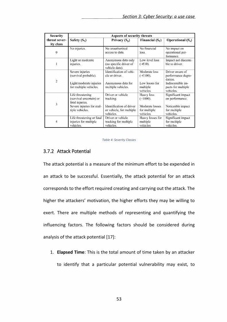
To accommodate this more complex situation the classification proposed
here (see Table 4) separates and categorizes different aspects of the
consequences of possible security breaches.
Section 3: Cyber Security: a use case
53
Table 4: Severity Classes
3.7.2 Attack Potential
The attack potential is a measure of the minimum effort to be expended in
an attack to be successful. Essentially, the attack potential for an attack
corresponds to the effort required creating and carrying out the attack. The
higher the attackers’ motivation, the higher efforts they may be willing to
exert. There are multiple methods of representing and quantifying the
influencing factors. The following factors should be considered during
analysis of the attack potential [17]:
1. Elapsed Time: This is the total amount of time taken by an attacker
to identify that a particular potential vulnerability may exist, to
Section 3: Cyber Security: a use case
54
develop an attack method and to sustain effort required mounting
the attack.
2. Specialist Expertise: This refers to the required level of general
knowledge of the underlying principles, product types or attack
methods.
3. Knowledge of the system under investigation: This refers to specific
expertise in relation to the system under investigation. Though it is
related to general expertise, it is distinct from that.
4. Window of opportunity: This has a relationship to the Elapsed Time
factor. Identification and exploitation of a vulnerability may require
considerable amounts of access to a system that may increase the
likelihood of detection of the attack. Some attack methods may
require considerable effort off-line, and only brief access to the
target to exploit. Access may also need to be continuous or over a
number of sessions.
5. IT hardware/software or other equipment: This refers to the
equipment required to identify and exploit vulnerability.
To determine for each path in an attack tree the attack potential required
to identify and exploit it, sum up the appropriate values from Table 6 and
apply Table 5 to classify the attack potential.
Section 3: Cyber Security: a use case
55
Table 5: Attack Potential
In this context the term “attack potential” is really describing the difficulty
of mounting a successful attack, while for risk analysis purposes a
probability measure is required. A high probability of successful attack is
assumed to correspond to the “basic” attack potential, since many possible
attackers will have the necessary attack potential. Conversely, a “high”
attack potential suggests a lower probability of successful attacks, since the
number of attackers with the necessary attack potential is expected to be
comparatively small. Consequently, Table 5 also proposes an associated
numerical scale that reflects the relative probability of success associated
with the attack potential in a more intuitive manner. The “attack
probability” measure (P) is higher for easier attacks that are associated with
lower attack potentials, and lower for more difficult attacks associated with
the higher attack potentials.
Section 3: Cyber Security: a use case
56
Table 6: Rating aspect of attack potential
3.7.3 Controllability
Where the severity vector includes a non-zero safety component, the risk
assessment may include an additional probability parameter that
represents the potential for the driver to influence the severity of the
Section 3: Cyber Security: a use case
57
outcome. In the MISRA Safety Analysis Guidelines [17] and ISO/DIS 26262
[18] this possibility is reflected in a qualitative measure referred to as
“controllability” (see Table 7).
Table 7: Controllability
3.7.4 Estimating Risk
Before estimating the risk for the hazard which has been used as root for
the attack tree, we need a last information, which is the Combined Attack
Potential.
In the tree, children may be connected to their parent with an AND or and
OR connection. The AND is explicitly specified through a circle, otherwise an
OR occurs implicitly.
The attack potential for OR and AND connections are:
𝐴𝑂𝑅(𝑃𝑖) = max{𝑃𝑖}
𝐴𝐴𝑁𝐷(𝑃𝑖) = min{𝑃𝑖}
The risk level (R, a vector) is determined from the severity (S) associated
with the attack objective and the combined attack potential (A) associated
Section 3: Cyber Security: a use case
58
with a particular attack method. This is achieved by mapping the severity
and attack potential to the risk using a “risk graph” approach. For severity
aspects that are not safety related the risk graph maps two parameters
(attack potential and severity) to a qualitative risk level. Combinations of
severity and combined attack potential are mapped to a range of “security
risk levels” (denoted Ri, where “i” is an integer) in Table 8 for non-safety
security threats. The security risk level attributed to an attack increases with
increasing severity and/or attack potential (the latter corresponding to
lower attack potential).
Table 8: Security Risk Level
In order to include the additional parameter (controllability) in the
assessment of safety-related security risks it is necessary to use of a
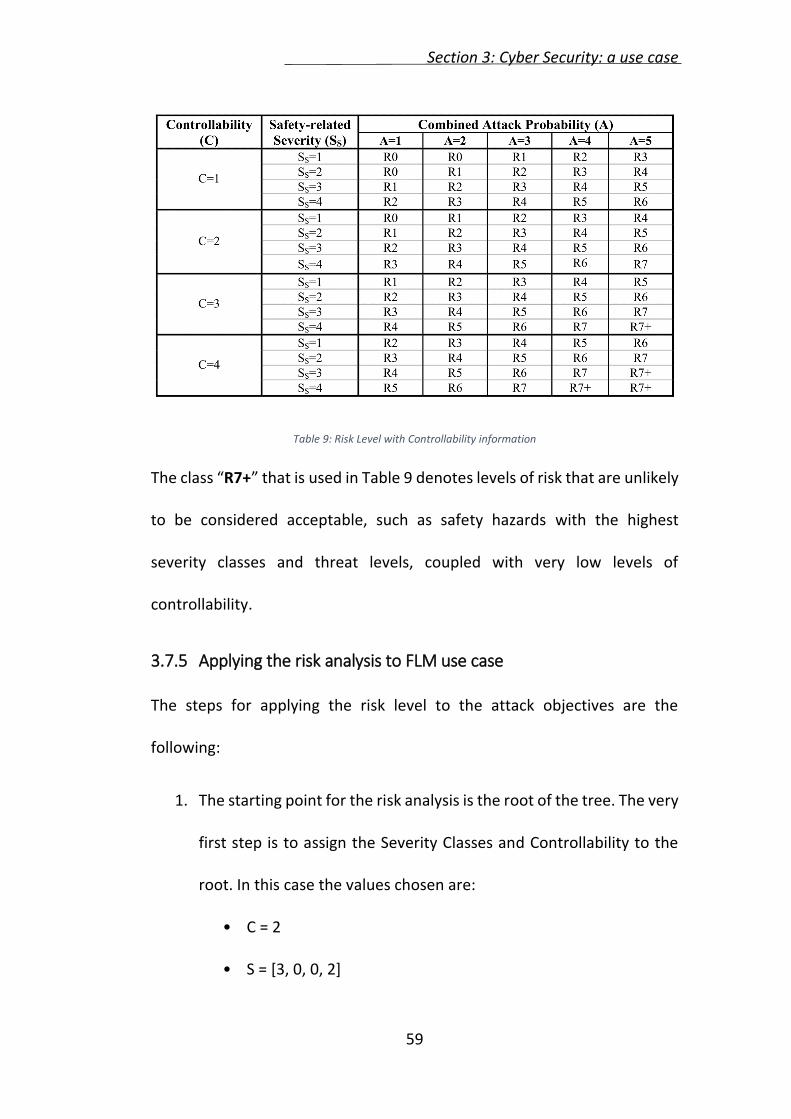
different risk graph as proposed in Table 9, which maps three parameters
(severity, attack probability, and controllability) to qualitative risk levels.
Section 3: Cyber Security: a use case
59
Table 9: Risk Level with Controllability information
The class “R7+” that is used in Table 9 denotes levels of risk that are unlikely
to be considered acceptable, such as safety hazards with the highest
severity classes and threat levels, coupled with very low levels of
controllability.
3.7.5 Applying the risk analysis to FLM use case
The steps for applying the risk level to the attack objectives are the
following:
1. The starting point for the risk analysis is the root of the tree. The very
first step is to assign the Severity Classes and Controllability to the
root. In this case the values chosen are:
• C = 2
• S = [3, 0, 0, 2]
Section 3: Cyber Security: a use case
60
2. The next step is to move to the leaves, where, for each leaf, the
attack potential has to be assigned;
After all the leaves have the attack potential assigned, the attack potential
for each leaf’s parent has to be computed, following the formulas for
AND/OR connections;
3. Following the same reasoning, the attack potential for all the nodes
has to be computed;
4. When the attack’s objectives have been reached, the risk level is
assigned following Table 8 or Table 9.
After all the computation have been done, the tree obtained is the one
shown in Figure 19.
Section 3: Cyber Security: a use case
61
Figure 19: Attack tree after risk levels are computed
It is possible to assess, by analysing the attack tree presented previously,
that the problem related to cyber security lies in the communications
flowing on the CAN bus. This result will be useful to identify which part of
the system must be enhanced.
Next sections will present the classical method for introducing security in
AUTOSAR during the modelling phase. Then an automatic process for
avoiding errors during such phase will be presented.
Section 4: Security annotations and Software Component extensions
62
4 SECURITY ANNOTATIONS AND SOFTWARE COMPONENT
EXTENSIONS
As previous sections highlighted, security is a priority to ensure that no
inconvenient occurs, which may harm the driver (and the car itself). The
solution to the lack of security is to ensure Confidentiality and Integrity to
system’s communications, in particular to those occurring over the CAN Bus.
4.1 AUTOSAR SECURITY MECHANISMS
Starting with AUTOSAR 4.0, cryptographic requirements were introduced in
order to support increasing automotive market demands in that field. In
order to implement the cryptographic requirements, AUTOSAR defines two
different specification documents:
• Crypto Abstraction Library (CAL) [19];
• Crypto Service Manager (CSM) [20].
4.1.1 Crypto Abstraction Library
The AUTOSAR library CAL provides other BSW modules and application
SWCs with cryptographic services. It offers C functions that can be called
from source code, i.e. from BSW modules, from SWC or from Complex
Drivers. As the CAL is a library, it is not related to a special layer of the
Section 4: Security annotations and Software Component extensions
63
AUTOSAR Layered Software Architecture. The services of the CAL are always
executed in the context of the calling function.
4.1.2 Crypto Service Manager
The CSM is located in the Services Layer of AUTOSAR layered architecture,
as shown in Figure 20. It offers standardized access to cryptographic services
for applications via the port mechanism.
Cryptographic services are, e.g., the computation of hashes, the verification
of asymmetrical signatures, or the symmetrical encryption of data. These
services depend on underlying cryptographic primitives and cryptographic
schemes (CRY).
CSM services use cryptographic algorithms that are implemented using a
software library or cryptographic hardware modules.
Section 4: Security annotations and Software Component extensions
64
Figure 20: AUTOSAR: Crypto Service Manager
The CSM services are generic. Consequently, the CSM allows different
applications to use the same service for different algorithms. While the
definition of the services, offered by the CSM, is part of the CSM
specification document, there is no specification in regards of the
cryptographic service primitives contained. It is up to a provider to specify,
implement and provide such for access by a CSM implementation.
Many CSM/CPL interfaces use the same cryptographic building blocks. Thus,
cryptographic building blocks should be implemented as separate modules
and be called from the CSM/CPL interfaces. This implies that the code for
cryptographic building blocks should not be implemented more than once.
Section 4: Security annotations and Software Component extensions
65
4.1.2.1 Locality of the CSM
Due to the fact that the CSM is an element of the AUTOSAR Services Layer,
the offered service can be used locally only – it is not possible to access the
service of the CSM directly via the VFB from a different ECU.
If this is needed, it is up to a provider to specify, implement and provide
some proxy for access of a CSM implementation, utilizing AUTOSAR
communication services for instance. In this case, it must be taken into
account that this raises security implications: any communication between
ECUs is done via not protected (somehow open accessible) communication
busses (e.g. CAN). This means, that unencrypted date, not yet signed data
or key material would be transmitted and might become stolen or
manipulated.
4.1.3 CSM and CAL
The AUTOSAR CSM and CAL specifications define the same cryptographic
functionality. This provided functionality covers the following areas:
Hash calculation;
Generation and verification of message authentication codes;
Random number generation;
Encryption and decryption using symmetrical algorithms;
Encryption and decryption using asymmetrical algorithms;
Section 4: Security annotations and Software Component extensions
66
Generation and verification of digital signature;
Key management operations;
As already stated, the AUTOSAR CSM and CAL specifications do not define
the cryptographic algorithms to be used in order to implement the required
functionality. It is up to the implementer to decide regarding based on his
assumptions or (better) based on customer requirements that are not
provided by AUTOSAR.
The existence of two BSW modules (a service module and a library),
providing the same (or similar) functionality, is for historical reasons: the
cryptographic library has been introduced for using cryptographic
functionality directly by bypassing the RTE, after the CSM has been defined
already. Even if both modules provide mostly the same functionality, both
use different mechanisms for communication.
4.2 USING THE CSM TO PROVIDE SECURITY FUNCTIONALITIES
As stated before, the CSM offers several security mechanisms. This section
will show how to include those functionalities in an AUTOSAR (release 4.2.2)
project. The FLM use case will be taken as example.
The manual procedure to include security is simplified in the following steps:
Section 4: Security annotations and Software Component extensions
67
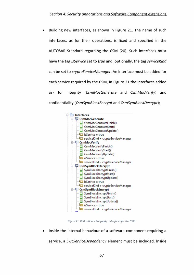
Building new interfaces, as shown in Figure 21. The name of such
interfaces, as for their operations, is fixed and specified in the
AUTOSAR Standard regarding the CSM [20]. Such interfaces must
have the tag isService set to true and, optionally, the tag serviceKind
can be set to cryptoServiceManager. An interface must be added for
each service required by the CSM, in Figure 21 the interfaces added
ask for integrity (CsmMacGenerate and CsmMacVerify) and
confidentiality (CsmSymBlockEncrypt and CsmSymBlockDecrypt);
Figure 21: IBM rational Rhapsody: Interfaces for the CSM.
Inside the internal behaviour of a software component requiring a
service, a SwcServiceDependency element must be included. Inside
Section 4: Security annotations and Software Component extensions
68
such element, it’s required to specify the client port(s)
(assignedPort), through which requiring the chosen CSM service and
the type of service (ServiceNeeds, specified in section 7.11 of [7])
required, in this case a CryptoServiceNeeds. This procedure is shown
in Figure 22.
Figure 22: IBM Rational Rhapsody: SWC Internal Behaviour specification for CSM services.
The procedure specified before has to be done for each SWC and CSM
service required. It’s clear that is a complex and error prone procedure. For
this reason, this work presents a tool for security modeling and automatic
code generation in AUTOSAR.
4.3 SECURITY MODELING AND AUTOMATIC CODE GENERATION IN
AUTOSAR
The tool produced has the aim to simplify the procedure described in the
previous section, to include security in AUTOSAR. It uses the ARXML file
Section 4: Security annotations and Software Component extensions
69
generated from the model to analyse the model and look for ad-hoc
elements inserted in the desc tag of data ports. Those elements are the
following:
NONE: no security required;
AUTH: authentication required, CsmSymEncrypt and CsmSymDecrypt
must be required to the CSM;
INTEGR: integrity required, CsmMacGenerate and CsmMacVerify
must be required to the CSM;
BOTH: both authentication and integrity are required.
In addition, the user can specify, after the security specification above, the
will of adding a brand new component (Filter) or to include security directly
inside the original component. The possible uses of the desc field is
summarized below:
SecurityNeeds={INTEG,CONF,BOTH};
NewComponent={TRUE,FALSE}.
4.4 APPLICATION TO THE FRONT LIGHT MANAGER USE CASE
In this section it is provided the application of the tool described in the
previous sections to the Front Light Manager use case scenario.
Section 4: Security annotations and Software Component extensions
70
The very first step is to identify which connections require security and
which kind of security they require.
The connection between IgnitionKey and LightRequest requires
confidentiality;
The connection between FLM and HMI requires integrity;
The connection between FLM and OBC requires integrity.
After adding the security tags to the AUTOSAR model and producing the
ARXML file, the latter is parsed by the python tool. It produces a new ARXML
file as output. The file obtained can be loaded into IBM Rational Rhapsody
to see graphically the result, which can be seen in Figure 23.
Figure 23: FLM model after python tool parsing
Section 5: Crypto Service Manager implementation
71
5 CRYPTO SERVICE MANAGER IMPLEMENTATION
This section will present an implementation of the CSM in C-language,
according with the AUTOSAR standard documentation. The modules
implemented are the symmetrical encryption/decryption, symmetrical
block encryption/decryption and the MAC generation/verification. The
following sections will present how they are designed and implemented. In
the following, the keyword <Service> will be used in place of
The CSM supports processing of a single instance of each service at a time.
The implementation of those CSM services which expect arbitrary amounts
of user data (i.e. hashing, encryption, etc.) shall be based on the streaming
approach with start, update and finish functions. This is the case of the
implementation proposed.
5.2 CONFIGURATION
Each service configuration is realized as a constant structure of type
Csm_<Service>ConfigType, and have a name which can be configured.
Section 5: Crypto Service Manager implementation
72
It is possible to configure synchronous and asynchronous job processing. In
this work the synchronous one has been chosen, so the interface functions
immediately compute the result.
5.3 SYNCHRONISATION BETWEEN APPLICATION AND CSM MODULE
CSM services which do not expect arbitrary amounts of user data, only have
to provide an API Csm_<Service>(). These services have to be handled as
simple function calls.
CSM services which expect arbitrary amounts of user data (as in the case of
this work), shall provide the APIs Csm_<Service>Start(),
Csm_<Service>Update() and Csm_<Service>Finish(). All applications have
to follow the rules presented by the next sections.
5.3.1 Initialization
The application calls the Csm_<Service>Start() request, passing a valid
service configuration to the start function. The start function checks the
validity of the configuration received.
If an instance of the service is being processed, the start function returns
CSM_E_BUSY. If no instance of the service is being processed when the
Csm_<Service>Start() is called, the function configures the CSM
immediately and return the status of the service.
Section 5: Crypto Service Manager implementation
73
5.3.2 Update
The application calls the Csm_<Service>Update() request, passing data
which are necessary for the computation of the service to the update
function. The update function checks whether the current service is already
initialized. If the service is not yet initialized, the update function returns
E_NOT_OK.
The CSM assumes that the data provided to the Csm_<Service>Update() will
not change until it returns.
If the service has been initialized, the update function immediately
processes the given data and return the status of the update.
5.3.3 Finish
The application calls the Csm_<Service>Finish() request, passing the result
buffer and optional data which is necessary for the finishing of the
cryptographic service to the finish function.
The finish function checks whether the current service is already initialized.
If it has not been initialized before, the finish function returns E_NOT_OK. If
the service has been initialized before, the finish function shall immediately
process the given data, finish the computation of the current cryptographic
service, store the result in the result buffer and returns the status of the
finish function.
Section 5: Crypto Service Manager implementation
74
The CSM assumes that the data provided to the Csm_<Service>Finish() will
not change until it returns.
5.4 API TYPES
This section will explore all the types and data structure used for the
implementation the cryptographic modules.
5.4.1 Enumerators and typedef
The starting point to describe the API types, are the description of all the
enumerators and typedefs used. The list of the typedefs follows:
typedef uint16 Csm_ConfigIdType: numeric ID of a CSM service
configuration, unique within the service;
typedef uint8 Csm_AlignType: scalar type which has maximum
alignment restrictions on the given platform. This value is configured
by the CsmMaxAlignScalarType.
The return type of the API implemented is of type Std_ReturnType, which
can assume the following values:
E_OK: all the computations have been completed correctly;
E_NOT_OK: an error occurs;
CSM_E_BUSY: the cryptographic service is already serving another
client.
Section 5: Crypto Service Manager implementation
75
In case of a MAC verification, the result is of type Csm_VerifyResultType,
which can assume the following values:
CSM_E_VER_OK: verification correct;
CSM_E_VER_NOT_OK: verification failed.
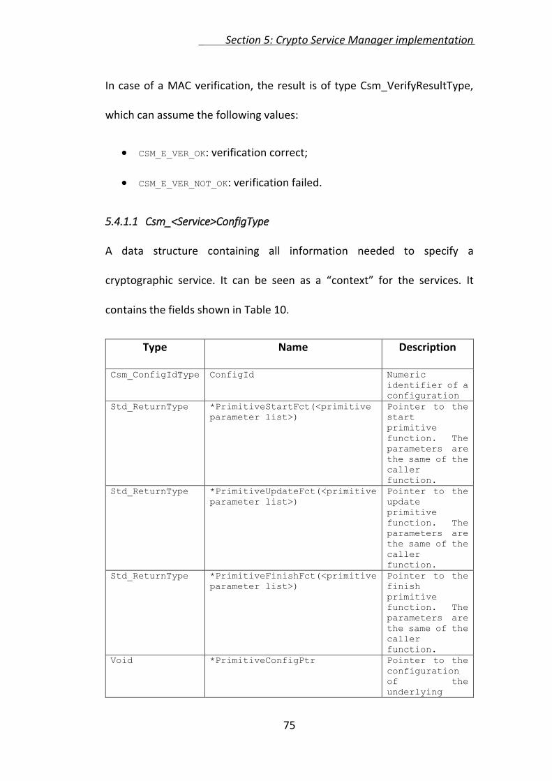
5.4.1.1 Csm_<Service>ConfigType
A data structure containing all information needed to specify a
cryptographic service. It can be seen as a “context” for the services. It
contains the fields shown in Table 10.
Type Name Description
Csm_ConfigIdType ConfigId Numeric
identifier of a
configuration
Std_ReturnType *PrimitiveStartFct(<primitive
parameter list>)
Pointer to the
start
primitive
function. The
parameters are
the same of the
caller
function.
Std_ReturnType *PrimitiveUpdateFct(<primitive
parameter list>)
Pointer to the
update
primitive
function. The
parameters are
the same of the
caller
function.
Std_ReturnType *PrimitiveFinishFct(<primitive
parameter list>)
Pointer to the
finish
primitive
function. The
parameters are
the same of the
caller
function.
Void *PrimitiveConfigPtr Pointer to the
configuration
of the
underlying
Section 5: Crypto Service Manager implementation
76
cryptographic
primitive.
Table 10: elements of the service configuration structure.
5.4.1.2 Cry_<Primitive>ConfigType
A data structure containing all information needed to specify a
cryptographic primitive. It can be seen as a “context” for the primitive. The
fields of this structure differs for each primitive, as, according to the
AUTOSAR standard, they are implementation specific.
5.5 SYMMETRICAL BLOCK INTERFACE
A block cipher is a symmetric key cipher operating on a fixed-length blocks,
with an unvarying transformation. A block cipher encryption algorithm
takes a n-block of plaintext as input, and produces an output of n-bit block
of ciphertext. The transformation is controlled by a second input: the secret
key.
Decryption is similar, the decryption algorithm takes as input a n-bit block
of ciphertext and a secret key, and produce the original n-bit block plaintext.
Next sections will present the specification of the functions used for
encryption and decryption.
5.5.1 Csm_SymBlockEncryptStart
Service name Csm_SymBlockEncryptStart
Syntax Std_ReturnType Csm_SymBlockEncryptStart(
Csm_ConfigType cfgId, const Csm_SymKeyType
*keyPtr)
Section 5: Crypto Service Manager implementation
77
Parameters (in)
cfgId Identifier of the CSM module configuration
keyPtr Pointer to the key structure, used by the encryption algorithm
Return values Std_ReturnType E_OK: request successful E_NOT_OK: request failed CSM_E_BUSY: request failed, service is still busy
Description The interface is used to initialize the symmetrical block encryption service of the CSM module. If the service is busy, the function returns CSM_E_BUSY. Otherwise the function stores the given configuration and call the Cry_<Primitive>Start of the primitive identified by the cfgId and return the value returned by that function.
5.5.2 Csm_SymBlockEncryptUpdate
Service name Csm_SymBlockEncryptUpdate
Syntax Std_ReturnType Csm_SymBlockEncryptUpdate(
Csm_ConfigType cfgId, const uint8
*plainTextPtr,
uint32 plainTextLength, uint8 *cipherTextPtr,
uint32 *cipherTextLengthPtr)
Parameters (in)
cfgId Identifier of the CSM module configuration
plainTextPtr Pointer to the plaintext buffer
plainTextLength Length of the plaintext
cipherTextPtr Pointer to the ciphertext buffer
cipherTextLengthPtr Pointer to the memory location where the length of the ciphertext is stored. On calling, this parameter shall contain the size of the buffer provided by the cipherTextPtr. When the request has finished, the amount of data that has been encrypted shall be stored
Description The interface is used to feed the symmetrical block encryption service with the input data. If the service is not busy, the function returns E_NOT_OK. Otherwise the function calls the Cry_<Primitive>Update and return the value returned by that function.
5.5.3 Csm_SymBlockEncryptFinish
Service name Csm_SymBlockEncryptFinish
Syntax Std_ReturnType Csm_SymBlockEncryptFinish(
Csm_ConfigType cfgId)
Parameters (in)
cfgId Identifier of the CSM module configuration
Return values Std_ReturnType E_OK: request successful E_NOT_OK: request failed CSM_E_BUSY: request failed, service is still busy
Description The interface is used finish the symmetrical block encryption service. If the service is not busy, the function returns E_NOT_OK. Otherwise the function calls the Cry_<Primitive>Finish and return the value returned by that function.
5.5.4 Csm_SymBlockDecryptStart
Service name Csm_SymBlockDecryptStart
Syntax Std_ReturnType Csm_SymBlockDecryptStart(
Csm_ConfigType cfgId, const Csm_SymKeyType
*keyPtr)
Parameters (in)
cfgId Identifier of the CSM module configuration
keyPtr Pointer to the key structure, used by the encryption algorithm
Return values Std_ReturnType E_OK: request successful E_NOT_OK: request failed CSM_E_BUSY: request failed, service is still busy
Description The interface is used to initialize the symmetrical block decryption service of the CSM module.
Section 5: Crypto Service Manager implementation
79
If the service is busy, the function returns CSM_E_BUSY. Otherwise the function stores the given configuration and call the Cry_<Primitive>Start of the primitive identified by the cfgId and return the value returned by that function.
5.5.5 Csm_SymBlockDecryptUpdate
Service name Csm_SymBlockDecryptUpdate
Syntax Std_ReturnType Csm_SymBlockEncryptUpdate(
Csm_ConfigType cfgId, const uint8
*cipherTextPtr,
uint32 cipherTextLength, uint8 *plainTextPtr,
uint32 *plainTextLengthPtr)
Parameters (in)
cfgId Identifier of the CSM module configuration
cipherTextPtr Pointer to the ciphertext buffer
cipherTextLength Length of the ciphertext
plainTextPtr Pointer to the plaintext buffer
plainTextLengthPtr Pointer to the memory location where the length of the plaintext is stored. On calling, this parameter shall contain the size of the buffer provided by the plainTextPtr. When the request has finished, the amount of data that has been decrypted shall be stored
Return values Std_ReturnType E_OK: request successful E_NOT_OK: request failed CSM_E_BUSY: request failed, service is still busy
Description The interface is used to feed the symmetrical block decryption service with the input data. If the service is not busy, the function returns E_NOT_OK. Otherwise the function calls the Cry_<Primitive>Update and return the value returned by that function.
Section 5: Crypto Service Manager implementation
80
5.5.6 Csm_SymBlockDecryptFinish
Service name Csm_SymBlockDecryptFinish
Syntax Std_ReturnType Csm_SymBlockEncryptFinish(
Csm_ConfigType cfgId)
Parameters (in)
cfgId Identifier of the CSM module configuration
Return values Std_ReturnType E_OK: request successful E_NOT_OK: request failed CSM_E_BUSY: request failed, service is still busy
Description The interface is used finish the symmetrical block decryption service. If the service is not busy, the function returns E_NOT_OK. Otherwise the function calls the Cry_<Primitive>Finish and return the value returned by that function.
5.6 SYMMETRICAL INTERFACE
The Symmetrical Interface implements an algorithm which uses identical
cryptographic keys for both decryption and encryption. The keys are shared
secret between two or more parties.
Next sections will describe each of the function implemented.
5.6.1 Csm_SymEncryptStart
Service name Csm_SymEncryptStart
Syntax Std_ReturnType Csm_SymEncryptStart(
Csm_ConfigType cfgId, const Csm_SymKeyType
*keyPtr,
const uint8 *InitVectorPtr, uint32
InitVectorLength)
Parameters (in)
cfgId Identifier of the CSM module configuration
keyPtr Pointer to the key structure, used by the encryption algorithm
Section 5: Crypto Service Manager implementation
81
InitVectorPtr Holds a pointer to the initialization vector used during the encryption computation
InitVectorLength Holds the length of the initialization vector used during the encryption computation
Return values Std_ReturnType E_OK: request successful E_NOT_OK: request failed CSM_E_BUSY: request failed, service is still busy
Description The interface is used to initialize the symmetrical encryption service of the CSM module. If the service is busy, the function returns CSM_E_BUSY. Otherwise the function stores the given configuration and call the Cry_<Primitive>Start of the primitive identified by the cfgId and return the value returned by that function.
5.6.2 Csm_SymEncryptUpdate
Service name Csm_SymEncryptUpdate
Syntax Std_ReturnType Csm_SymEncryptUpdate(
Csm_ConfigType cfgId, const uint8
*plainTextPtr,
uint32 plainTextLength, uint8 *cipherTextPtr,
uint32 *cipherTextLengthPtr)
Parameters (in)
cfgId Identifier of the CSM module configuration
plainTextPtr Pointer to the plaintext buffer
plainTextLength Length of the plaintext
cipherTextPtr Pointer to the ciphertext buffer
cipherTextLengthPtr Pointer to the memory location where the length of the ciphertext is stored. On calling, this parameter shall contain the size of the buffer provided by the cipherTextPtr. When the request has finished, the amount of data that has been encrypted shall be stored
E_NOT_OK: request failed CSM_E_BUSY: request failed, service is still busy
Description The interface is used to feed the symmetrical encryption service with the input data. If the service is not busy, the function returns E_NOT_OK. Otherwise the function calls the Cry_<Primitive>Update and return the value returned by that function.
5.6.3 Csm_SymEncryptFinish
Service name Csm_SymEncryptFinish
Syntax Std_ReturnType Csm_SymEncryptFinish(
Csm_ConfigType cfgId, uint8 *cipherTextPtr,
uint32 *cipherTextLengthPtr)
Parameters (in)
cfgId Identifier of the CSM module configuration
cipherTextPtr Holds a pointer to the memory location which will hold the encrypted text
cipherTextLengthPtr Holds a pointer to the memory location which holds the length of the encrypted text. On calling, this parameter shall contain the size of the buffer provided by the cipherTextPtr. When the request has finished, the amount of data that has been encrypted shall be stored
Return values Std_ReturnType E_OK: request successful E_NOT_OK: request failed CSM_E_BUSY: request failed, service is still busy
Description The interface is used finish the symmetrical encryption service. If the service is not busy, the function returns E_NOT_OK. Otherwise the function calls the Cry_<Primitive>Finish and return the value returned by that function.
Section 5: Crypto Service Manager implementation
83
5.6.4 Csm_DecryptStart
Service name Csm_SymDecryptStart
Syntax Std_ReturnType Csm_SymDecryptStart(
Csm_ConfigType cfgId, const Csm_SymKeyType
*keyPtr,
const uint8 *InitVectorPtr, uint32
InitVectorLength)
Parameters (in)
cfgId Identifier of the CSM module configuration
keyPtr Pointer to the key structure, used by the encryption algorithm
InitVectorPtr Holds a pointer to the initialization vector used during the encryption computation
InitVectorLength Holds the length of the initialization vector used during the encryption computation
Return values Std_ReturnType E_OK: request successful E_NOT_OK: request failed CSM_E_BUSY: request failed, service is still busy
Description The interface is used to initialize the symmetrical decryption service of the CSM module. If the service is busy, the function returns CSM_E_BUSY. Otherwise the function stores the given configuration and call the Cry_<Primitive>Start of the primitive identified by the cfgId and return the value returned by that function.
5.6.5 Csm_SymDecryptUpdate
Service name Csm_SymDecryptUpdate
Syntax Std_ReturnType Csm_SymDecryptUpdate(
Csm_ConfigType cfgId, const uint8
*cipherTextPtr,
uint32 cipherTextLength, uint8 *plainTextPtr,
uint32 *plainTextLengthPtr)
Parameters (in)
cfgId Identifier of the CSM module configuration
plainTextPtr Pointer to the plaintext buffer
plainTextLength Length of the plaintext.
Section 5: Crypto Service Manager implementation
84
On calling, this parameter shall contain the size of the buffer provided by the plainTextPtr. When the request has finished, the amount of data that has been decrypted shall be stored
cipherTextPtr Pointer to the ciphertext buffer
cipherTextLengthPtr Pointer to the memory location where the length of the ciphertext is stored
Return values Std_ReturnType E_OK: request successful E_NOT_OK: request failed CSM_E_BUSY: request failed, service is still busy
Description The interface is used to feed the symmetrical decryption service with the input data. If the service is not busy, the function returns E_NOT_OK. Otherwise the function calls the Cry_<Primitive>Update and return the value returned by that function.
5.6.6 Csm_SymDecryptFinish
Service name Csm_SymDecryptFinish
Syntax Std_ReturnType Csm_SymDecryptFinish(
Csm_ConfigType cfgId, uint8 *plainTextPtr,
uint32 *plainTextLengthPtr)
Parameters (in)
cfgId Identifier of the CSM module configuration
plainTextPtr Holds a pointer to the memory location which will hold the encrypted text
plainTextLengthPtr Holds a pointer to the memory location which holds the length of the decrypted text. On calling, this parameter shall contain the size of the buffer provided by the plainTextPtr. When the request has finished, the amount of data that has been decrypted shall be stored
Section 5: Crypto Service Manager implementation
85
Return values Std_ReturnType E_OK: request successful E_NOT_OK: request failed CSM_E_BUSY: request failed, service is still busy
Description The interface is used finish the symmetrical decryption service. If the service is not busy, the function returns E_NOT_OK. Otherwise the function calls the Cry_<Primitive>Finish and return the value returned by that function.
5.7 MAC INTERFACE
A Message Authentication Code (MAC) is a short piece of information used
to authenticate a message. A MAC algorithm accepts as input a secret key
and an arbitrary-length message to be authenticated, and produces a MAC
as output. The MAC protects the message both for authenticity and
integrity, as only who possesses the secret key can verify the MAC and
detect any changes to the message content.
Next sections will describe each of the function implemented.
5.7.1 Csm_MacGenerateStart
Service name Csm_SymBlockDecryptStart
Syntax Std_ReturnType Csm_SymBlockDecryptStart(
Csm_ConfigType cfgId, const Csm_SymKeyType
*keyPtr)
Parameters (in)
cfgId Identifier of the CSM module configuration
keyPtr Pointer to the key structure, used by the encryption algorithm
Description The interface is used to initialize the MAC generate service of the CSM module. If the service is busy, the function returns CSM_E_BUSY. Otherwise the function stores the given configuration and call the Cry_<Primitive>Start of the primitive identified by the cfgId and return the value returned by that function.
5.7.2 Csm_MacGenerateUpdate
Service name Csm_SymBlockDecryptUpdate
Syntax Std_ReturnType Csm_SymBlockEncryptUpdate(
Csm_ConfigType cfgId, const uint8 *dataPtr,
uint32 dataLength)
Parameters (in)
cfgId Identifier of the CSM module configuration
dataPtr Pointer to the input buffer
dataLength Length of the input buffer
Return values Std_ReturnType E_OK: request successful E_NOT_OK: request failed CSM_E_BUSY: request failed, service is still busy
Description The interface is used to feed the MAC generate service with the input data. If the service is not busy, the function returns E_NOT_OK. Otherwise the function calls the Cry_<Primitive>Update and return the value returned by that function.
5.7.3 Csm_MacGenerateFinish
Service name Csm_MacGenerateFinish
Syntax Std_ReturnType Csm_SymBlockEncryptFinish(
Csm_ConfigType cfgId, uint8 *resultPtr,
uint32 *resultLengthPtr, boolean
TruncationIsAllowed)
Parameters (in)
cfgId Identifier of the CSM module configuration
resultPtr Pointer to the output buffer
Section 5: Crypto Service Manager implementation
87
resultLengthPtr Pointer to the length of the output buffer
TruncationIsAllowed TRUE: truncation is allowed FALSE: truncation not allowed
Return values Std_ReturnType E_OK: request successful E_NOT_OK: request failed CSM_E_BUSY: request failed, service is still busy
Description The interface is used finish the MAC generation service. If the service is not busy, the function returns E_NOT_OK. Otherwise the function calls the Cry_<Primitive>Finish and return the value returned by that function.
5.7.4 Csm_MacVerifyStart
Service name Csm_SymBlockDecryptStart
Syntax Std_ReturnType Csm_SymBlockDecryptStart(
Csm_ConfigType cfgId, const Csm_SymKeyType
*keyPtr)
Parameters (in)
cfgId Identifier of the CSM module configuration
keyPtr Pointer to the key structure, used by the encryption algorithm
Return values Std_ReturnType E_OK: request successful E_NOT_OK: request failed CSM_E_BUSY: request failed, service is still busy
Description The interface is used to initialize the MAC verification service of the CSM module. If the service is busy, the function returns CSM_E_BUSY. Otherwise the function stores the given configuration and call the Cry_<Primitive>Start of the primitive identified by the cfgId and return the value returned by that function.
5.7.5 Csm_MacVerifyUpdate
Service name Csm_SymBlockDecryptUpdate
Syntax Std_ReturnType Csm_SymBlockEncryptUpdate(
Section 5: Crypto Service Manager implementation
88
Csm_ConfigType cfgId, const uint8 *dataPtr,
uint32 dataLength)
Parameters (in)
cfgId Identifier of the CSM module configuration
dataPtr Pointer to the input buffer
dataLength Length of the input buffer
Return values Std_ReturnType E_OK: request successful E_NOT_OK: request failed CSM_E_BUSY: request failed, service is still busy
Description The interface is used to feed the MAC verificatio service with the input data. If the service is not busy, the function returns E_NOT_OK. Otherwise the function calls the Cry_<Primitive>Update and return the value returned by that function.
5.7.6 Csm_MacVerifyFinish
Service name Csm_MacGenerateFinish
Syntax Std_ReturnType Csm_SymBlockEncryptFinish(
Csm_ConfigType cfgId, uint8 *MacPtr,
uint32 *MacLengthPtr, Csm_VerifyResultType
*resultPtr)
Parameters (in)
cfgId Identifier of the CSM module configuration
MacPtr Pointer to the output buffer
MacLengthPtr Pointer to the length of the output buffer
resultPtr Pointer to the memory location of the result of the MAC verification.
Return values Std_ReturnType E_OK: request successful E_NOT_OK: request failed CSM_E_BUSY: request failed, service is still busy
Description The interface is used finish the MAC verification service. If the service is not busy, the function returns E_NOT_OK. Otherwise the function calls the Cry_<Primitive>Finish and return the value returned by that function.
Section 5: Crypto Service Manager implementation
89
5.8 PRIMITIVES
All functions above call inside their body a primitive. Primitives are divided
in:
Cry_<Primitive>Start();
Cry_<Primitive>Update();
Cry_<Primitive>Finish().
Where the keyword <Primitive> is used for SymBlockEncrypt,
SymBlockDecrypt, MacGenerate and MacVerify.
All the primitives have the same argument and return type of the functions
which call them. The only exception is for start primitives, which has a
parameter of type const void *cfgPtr instead of Csm_ConfigIdType cfgId.
When calling these APIs, the parameter cfgPtr has to point to a constant
variable of type Cry_<Primitive>ConfigType, but need to be cast to const
void *. Reason for this is to have common definition of the parameter list
of this API for all primitives of one service, because in the structure
Csm_<Service>ConfigType one element is a function pointer to this API.
Section 6: Conclusions
90
6 CONCLUSIONS
This thesis analyses the problem of security in automotive applications. In
particular, integrity and confidentiality properties of inter-ECUs
communications are addressed.
An extension of the security modelling concepts currently available in
AUTOSAR have been proposed. Developers specify integrity and
confidentiality security requirements by adding security tags in the
description field of AUTOSAR software components.
A tool has been developed that, starting from the AUTOSAR model
specification with the security annotations, automatically generates
AUTOSAR security components that uses the services of the Crypto Service
Manager (CSM) to satisfy the high level requirement provided by the user.
Finally, following the standard specified for the AUTOSAR CSM, a Crypto
Service Manager library has been developed. The library, accessible by the
application layer, implements integrity by the mean of the MAC
Generation/Verification Interface and confidentiality using the Symmetric
Encryption/Decryption Interface. The library has been written in
C-programming language and uses OpenSSL as cryptographic primitives.
Section 6: Conclusions
91
As future work, the Crypto Service Manager library could be used for
simulation purposes, in particular to measure the resilience to cyber-
attacks, and for performance evaluations.
References
92
REFERENCES
[1] S. Checkoway, D. McCoy, B. Kantor, D. Anderson, H. Shacham and S.
Savage, “Comprehensive Experimental Analyses of Automotive Attack
Surfaces”.
[2] “AUTOSAR Safety use case example, release 4.2.2.,” [Online].