128
University of the Arts London Mechanical, Electrical & Plumbing Design Particulars Document UAL Estates Department Date Version April 2017 3.0

University of the Arts London Mechanical, Electrical &
Plumbing Design Particulars Document
UAL Estates Department
Date Version April 2017 3.0
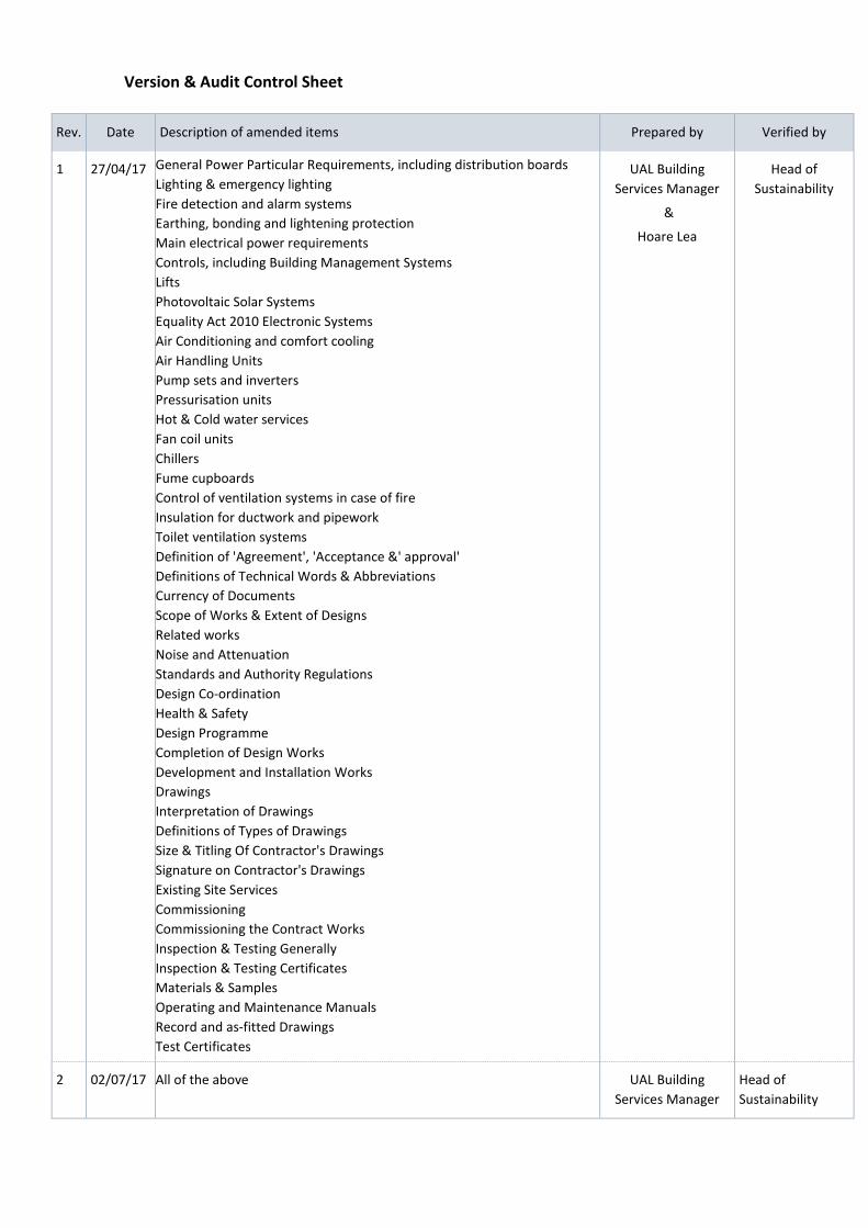
Version & Audit Control Sheet
Rev. Date Description of amended items Prepared by Verified by
1 27/04/17 General Power Particular Requirements, including distribution boards Lighting & emergency lighting Fire detection and alarm systems Earthing, bonding and lightening protection Main electrical power requirements Controls, including Building Management Systems Lifts Photovoltaic Solar Systems Equality Act 2010 Electronic Systems Air Conditioning and comfort cooling Air Handling Units Pump sets and inverters Pressurisation units Hot & Cold water services Fan coil units Chillers Fume cupboards Control of ventilation systems in case of fire Insulation for ductwork and pipework Toilet ventilation systems Definition of 'Agreement', 'Acceptance &' approval' Definitions of Technical Words & Abbreviations Currency of Documents Scope of Works & Extent of Designs Related works Noise and Attenuation Standards and Authority Regulations Design Co-ordination Health & Safety Design Programme Completion of Design Works Development and Installation Works Drawings Interpretation of Drawings Definitions of Types of Drawings Size & Titling Of Contractor's Drawings Signature on Contractor's Drawings Existing Site Services Commissioning Commissioning the Contract Works Inspection & Testing Generally Inspection & Testing Certificates Materials & Samples Operating and Maintenance Manuals Record and as-fitted Drawings Test Certificates
UAL Building Services Manager
&
Hoare Lea
Head of Sustainability
2 02/07/17 All of the above UAL Building Services Manager
Head of Sustainability

Rev. Date Description of amended items Prepared by Verified by
UAL Head of Projects
UAL Head of FM
UAL Estates Inform. Manager

Contents 1.0 Introduction 2.0 Electrical General Power Particular Requirements, including distribution boards Lighting & emergency lighting Fire detection and alarm systems Earthing, bonding and lightening protection Main electrical power requirements
Controls, including Building Management Systems Lifts Photovoltaic Solar Systems Equality Act 2010 Electronic Systems
3.0 Mechanical Air Conditioning and comfort cooling Air Handling Units Pump sets and inverters Pressurisation units Hot & Cold water services Fan coil units Chillers Fume cupboards Control of ventilation systems in case of fire Insulation for ductwork and pipework Toilet ventilation systems 4.0 Provisions & Use of Document
Definition of 'Agreement', 'Acceptance &' approval' Definitions of Technical Words & Abbreviations Currency of Documents Scope of Works & Extent of Designs Related works Noise and Attenuation Standards and Authority Regulations Design Co-ordination Health & Safety Design Programme Completion of Design Works Development and Installation Works Drawings Interpretation of Drawings Definitions of Types of Drawings Size & Titling Of Contractor's Drawings Signature on Contractor's Drawings Existing Site Services Commissioning Commissioning the Contract Works Inspection & Testing Generally Inspection & Testing Certificates Materials & Samples Operating and Maintenance Manuals Record and as-fitted Drawings Test Certificates

1.0 Introduction 1.1 General Introduction The purpose of this document is to provide design information regarding the University of the Arts London (UAL) for Main Contractors and Sub-Contractors who are engaged by the Estates Department or associated Colleges. This document shall be read in conjunction with all relevant British Standards and Codes of Practice; it does not seek to replace industry-standard design guidance or practice. It is intended to provide UAL’s aspirations to ensure building services align with the University’s strategic ambitions (http://www.arts.ac.uk/about-ual/strategy-governance/ual-strategy-2015-22/) and improve the student experience as much as possible. It should be noted that this document describes particular requirements it is to be read in conjunction with other university documentation such as the UAL Access Audit Specifications Document with regard to the Equalities Act 2010, UAL Design Brief for Sustainability and Heating and Cooling Policy (http://www.arts.ac.uk/about-ual/sustainability-at-ual/sustainability-documentation/). All approved contractors, consultants or suppliers will be expected to comply with the particular requirements when preparing any information for works that include electrical, mechanical or plumbing (MEP) assets that affect administration offices, teaching spaces (including workshops) and Halls of Residence. The university is also an accredited ISO50001 organisation. 1.2 UAL Preferred Manufacturers List The choice of components for MEP designs are to be selected with particular reference to their ease of use, frequency of maintenance, ease of maintenance, ease of upgrading or renewal and their ability to offer future flexibility and adaptability. All components shall be selected where available from the ‘UAL Preferred Manufacturers List’. Installation techniques, material selections, services installations and finishes shall all offer good value for money, and offer a solution that provides minimal environmental impact, be energy efficient, good life expectancy and low maintenance as well as conforming to any manufacturer’s requirements. 1.3 Variations Should Main Contractors or Sub-Contractors find it necessary to incorporate alternative standards or requirements to those stated within the following document then approval shall be sought in writing from the university by way of an ‘MEP Variation Report’. Main Contractors and Sub-Contractors will be required to justify (and potentially demonstrate), with written documentation, that the varied proposal will provide equivalent or better performance, energy efficiency, sustainability or result in the same or improved whole life costing and be of equal or better value.
1

1.4 Contractor responsibility This document indicates the minimum performance requirements of the system but the Contractor shall retain full responsibility for provision of a complete and satisfactory installation to meet all of the standards stated within the document, all current statutory requirements and general industry good practice. The Contractor is required to provide complete and fully functional systems incorporating the details and functions described herein. The Contractor is at liberty to satisfy the following requirements by the use of any adequate equipment or systems. Any deviations from the design intent as described herein should, however, be submitted for the approval of the Head of Projects, the Head of Facilities Management or the appointment Design team. The Contractor shall ensure that design criteria for each asset/system shall be taken from the appropriate from this document. The Contractor shall allow for all necessary site visits in order to fully ascertain and accustom himself with the overall constraints associated with the site and access limitations. No claims shall be considered based on a lack of knowledge of the existing site conditions or constraints. The design criteria (and drawings if appropriate) are intended to convey the concept for the design and indicative areas of services. This design criteria is not intended to inhibit any Contractor from developing the concept within the limitations of the indicated equipment installation zones, provided the designs are fit for purpose. For example, all services must fit within such plant room areas and spaces pre-established for services under the concept intent design.
2.0 Electrical
2.1 General Power Particular Requirements, including distribution boards
All building engineering services components shall be selected where available from Manufacturers listed within the UAL Preferred Manufacturers List v1 The Contractor is to comply with the requirements set out within the UAL Health and Safety procedures. The contractor shall consult with the UAL Authorised Engineer (or Halls Manager in the case of a Halls of Residence) prior to undertaking design works on existing or new proposed general small power to ensure UAL particular requirements are understood. The Main Contractor will be responsible for investigating and surveying electrical installations that require to be modified to check suitability of the current electrical installation and LV Switchgear for the new works. This will include assessing non-compliances with BS7671 prior to works commencing and incorporating any remedial works to ensure compliance is achieved on completion of the works.
2

The contractor will submit technical proposals to the UAL Building Services Manager (or Halls Manager in the case of a Halls of Residence) outlining the proposed works and identifying activities that will have a direct impact on the operational use of the UAL facilities. The Main Contractor will ensure the design meets the following requirements; To provide distributed power supplies using 400-V three-phase 50-Hz circuits and 230-V single-phase 50-Hz circuits and any other voltages/frequencies within the definition of LV. To provide a system of sufficient capacity to adequately meet the load characteristics of all individual circuits whilst remaining within equipment voltage and frequency tolerances. To provide a means of fault clearance and isolation on every circuit and coordinate protection of cables and switchgear. To provide a system designed to provide complete discrimination under fault conditions. To ensure that circuit design makes allowances for anticipated fault levels, installed cable length, environmental influences, diversity, installation methods, and that circuit disconnection is achieved safely within periods prescribed in BS 7671. To provide outlets that are suitable for the connected equipment and the environment in which they are installed. To ensure that all appliances are fused for the corresponding load, taking into account the manufacturer’s recommendation and any inrush current. 2.1.1 Design parameters This specification is written based on legislation, standards and guidance in force in the UK generally, and within England by default. The Main Contractor must comply fully with the edition (including amendments, replacements and associated normative references) of each of the following, current at the time of tender:
• The Building Regulations • The Disability Discrimination Act • The Electricity at Work Regulations • BS 1363 13 A plugs, socket-outlets, adaptors and connection units • BS 5424-3 Specification for control gear for voltages up to and including 1000 V
a.c. and 1200 V d.c. Additional requirements for contactors subject to certification
• BS 5467 Electric cables. Thermosetting insulated, armoured cables of rated voltages 600/1000 V and 900/3300 V for fixed installations. specification
• BS 5724 Medical electrical equipment. Particular requirements for safety. • BS 6004 Electric cables. PVC insulated and PVC sheathed cables for voltages up
to and including 300/500 V, for electric power and lighting • BS 6231 Electric cables. Single core PVC insulated flexible cables of rated voltage
600/1000 V for switchgear and controlgear wiring
3

• BS 6396 Electrical systems in office furniture and educational furniture. • BS 6724 Electric cables. Thermosetting insulated, armoured cables of rated
voltages of 600/1000 V and 1900/3300 V for fixed installations, having low emission of smoke and corrosive gases when affected by fire.
• BS 7211 Electric cables. Thermosetting insulated and thermoplastic sheathed cables for voltages up to and including 450/750 V for electric power and lighting and having low emission of smoke and corrosive gases when affected by fire
• BS 7346 Components for smoke and heat control systems • BS 7540-3 Electric cables. Guide to use for cables with a rated voltage not
exceeding 450/750 V. National standard cables not included in HD 21 and HD 22
• BS 7629-1 Electric cables. Specification for 300/500 V fire resistant, screened, fixed installation cables having low emission of smoke and corrosive gases when affected by fire. Multicore cables
• BS 7657 Specification for cut-out assemblies up to 100 A rating, for power supplies to buildings
• BS 7671 Requirements for electrical installations. IET Wiring Regulations • BS 8519 Selection and installation of fire-resistant power and control
cable systems for life safety and fire-fighting applications. Code of practice
• BS 9999 Fire safety in the design, management and use of buildings. Code of practice
• BS EN 50525 Electric cables. Low voltage energy cables of rated voltages up to and including 450/750 V (U0/U)
• BS EN 50565 Electric cables. Guide to use for cables with a rated voltage not exceeding 450/750 V (U0/U)
• BS EN 55014 Electromagnetic compatibility. Requirements for household appliances, electric tools and similar apparatus
• BS EN 60269 Low voltage fuses • BS EN 60309-1 Plugs, socket-outlets and couplers for industrial purposes.
General requirements • BS EN 60309-2 Plugs, socket-outlets and couplers for industrial purposes.
Dimensional interchangeability requirements for pin and contact-tube accessories
• BS EN 60335 Household and similar electrical appliance. Safety • BS EN 60601-1 Medical electrical equipment. General requirements for basic
safety and essential performance • BS EN 60742 Isolating transformers and safety isolating transformers. • BS EN 60896-22 Stationary lead-acid batteries. Valve regulated types. • BS EN 60898 Electrical accessories. Circuit-breakers for overcurrent
protection for household and similar installations • BS EN 60909-0 Short-circuit currents in three-phase a.c. systems. Calculation of
currents • BS EN 60947-2 Low-voltage switchgear and controlgear. Circuit-breakers
4

• BS EN 60947-3 Low-voltage switchgear and controlgear. Switches, disconnectors, switch-disconnectors and fuse-combination units
• BS EN 61180 High-voltage test techniques for low-voltage equipment. Definitions, test and procedure requirements, test equipment
• BS EN 61439 Low-voltage switchgear and control gear assemblies • BS EN 62040 Uninterruptible power systems (UPS) • BS EN 62196-2 Plugs, socket-outlets, vehicle connectors and vehicle inlets.
Conductive charging of electric vehicles. Dimensional compatibility and interchangeability requirements for a.c. pin and contact-tube accessories
• IEC 60364-7-710 Electrical installations of buildings. Requirements for special installations or locations. Medical locations.
• IET Guidance Note 7 (GN7) Special locations Design Criteria
Design distributed power fully in accordance with BS 7671, taking into consideration, amongst other applicable design criteria, the following in respect of BS 7671:
• The requirements of Chapter 52 in respect of the general design and selection of wiring systems.
• The requirements of Chapter 43 in respect of protection provided against overcurrent. • The requirements of Chapter 41 in respect of protection against electric shock.
Adopt a grouping factor not exceeding 0.8, ambient temperature of 30°C, XLPE insulated conductors, and equally sized phase, neutral and CPC conductors. Design and configure ring and radial final circuit arrangements in accordance with BS 7671 as detailed in Regulation 433.1 and informed in Appendix 15. Ensure main and radial final circuits are designed to minimise disruption on failure of a circuit or operation of a protective device. Size circuit components to achieve disconnection times as described in BS 7671, Regulation 41.1. Provide RCD protection on power circuits to meet the requirements of BS 7671 and of the rating indicated by the distribution board schedules. Space outlets on different phases not less than 2 m apart. Do not exceed row spacing of 5 m, and 2.5 m from a wall, for plug-in busbar systems within raised floor areas. Allow 20% spare capacity in all final containment routes to enable additional outlets to be added. Comply with the requirements of Part 7 of BS 7671 for special installations or locations such as swimming pools, saunas and bathrooms.
5

Connect power supplies to all equipment associated with life safety and fire protection installations to the essential sections of the distribution systems via dedicated circuits, and design in accordance with BS 9999. Design the general power distribution system to provide: Offices
• primary plant sized for 50 W/m2 small power leads • riser distribution sized for 50 W/m2 small power leads • distribution sized for 25 W/m2 - 35 W/m2 in office buildings
Teaching spaces • primary plant sized for 50 W/m2 mechanical ventilated • Primary plant sized for 35 W/m2 naturally ventilated • distribution sized for 10 W/m2 for classrooms • distribution sized for 10 W/m2 for music, drama and dance Halls of Residence • 28 W/m2 for lighting, general power and mechanical power. A figure of 1.6 kW per
student can also be employed 2.1.2 System Description 2.1.3 Control requirements 2.1.4 Scope of works Existing system Provide extensions and enhancements to, and reconfiguration of, the existing general LV power installation ensuring that all components provided are fully compatible with the existing system’s operation including any software protocol. Ensure that installation and testing are undertaken in a planned and sequenced manner, in agreement with UAL to ensure minimal disruption to existing services. Should existing LV switchgear, small power or accessories systems be obsolete, the contractor shall submit an alternative design solution. Prior to this solution being considered the proposals shall be submitted for approval to UAL’s Approved Engineer for comment. Existing UAL buildings must remain operational during additions and/or amendments to the existing electrical installation. A method statement detailing temporary works must be provided and included within the project costs to ensure the electrical installation remain operational at all times. The works shall include all record drawings and software updates to incorporate electrical equipment, accessories, devices added or deleted from existing installation. Wiring types
6

Take responsibility for the final cable selection. Provide internal cabling in accordance with the following:
• BS 6004, 6491B XL-LSF, insulated only, single-core cable, 450/750-volt grade, contained in steel trunking and/or conduit
• BS 6724, XLPE insulated, LSF bedded, single wire armoured, LSF sheathed cable, 600/1000-volt grade unless otherwise specified. Arrange single-core wire armoured cables in trefoil and provide aluminium wire armour and non-ferrous or insulated gland plates to prevent circulating currents.
Provide copper/LS0H singles in trunking and/or conduit for the final circuits from the distribution boards. Provide external cabling in accordance with the following:
• BS 5467, XLPE insulated, single wire armoured, pre-sheathed cable, 600/1000-volt grade.
• Wire all life safety systems in accordance with the requirements of BS 8519 including but not limited to the below:
• wire the smoke ventilation systems to Category 3 specification, and in accordance with the requirements of BS 8519
• wire the power supply to emergency voice communication systems to Category 3 specification, and in accordance with the requirements of BS 8519
2.1.5 System components (Installation methods and containment) Use singles within conduit to feed final socket outlets, unless otherwise specified, to allow re-wiring. Provide final circuit wiring installed in a system of containment throughout its length. Run containment generally within the fabric of the building, within ceiling or raised access floor voids, providing concealed drops to items of equipment and socket outlets. In all areas other than service voids, roof areas, risers and plant rooms, conceal all cabling behind dry-lining, chased into walls etc., and flush-mount all outlets i.e. switches, socket outlets, connection units, etc. Provide galvanized steel cable trays and ladders where several cables are installed in close proximity and in accordance with the layout drawings. Ensure that the tray and ladder are medium-duty grade and post-dipped galvanized unless otherwise specified. Ensure that tray and ladder routes are continuous and arranged to provide horizontal cable ways between panels and distribution boards, and vertical cable ways in risers to interconnect to the floors, switch panels, basement and rooftop plant rooms. Paint exposed threads with rust-resisting paint. Ensure that conduit and trunking installations are completed prior to pulling in any circuit cables. Ensure that the trunking is galvanized unless otherwise specified.
7

Ensure that the insulation of the cabling system selected is equal to the maximum circuit voltage present within the trunking compartment and that the cable can operate satisfactorily within the electromagnetic environment prevailing in the trunking compartment, ie twisted pair and screened cabling, to provide maximum immunity and to minimise emissions. Where SWA cabling terminates in enclosures/isolators, provide “banjo” type connections to an earth lug to the respective earth terminal. Support cables located in escape routes in accordance with Regulation 521.11.201 such that they are not liable to premature collapse in the event of fire. Do not use non-metallic cable clips, cable ties or cable trunking as the sole means of support. Use fire-resistant means of support designed to prevent cables from falling into escape routes in the event of fire. Segregate power and data wiring by spacing the systems apart where they run in parallel, containing power within screened cables or containment. Ensure that power and data cables cross each other at right angles. Segregate the containment systems into the following categories, where possible:
• 230/400 volt • extra-low voltage systems, IT systems, security systems, TV systems • fire alarms • generator supplies • utility main supplies
For data processing applications, segregate cable terminals in distribution boards and /power distribution units. Do not use junction boxes as part of the project work; except in situations where it is proven to be wholly unavoidable and only then with the acceptance of UAL’s Approved Engineer. Provide a multi-compartment dado trunking system (with minimum 50 mm deep back box) for power data outlets where applicable. Ensure that the dado trunking systems are suitable for Cat-6 data structural cabling. Main Low Voltage (LV) Distribution Switchboards and Panels Switchgear General Requirements All switchgear must be metal clad, totally enclosed, rated at 500 volts and be of unit or cubicle construction. Construction must comply with the appropriate British Standard Specifications. LV switchgear must be combinations of fused switches, switch fuses, switch disconnectors, distribution boards etc. fitted with HBC cartridge type fuses complying with the appropriate British Standard Specifications.
8

Switchgear shall be constructed so that cable entry plates on non-demountable units and cubicles shall be readily removable to facilitate the forming of holes for cable boxes, conduit, trunking etc. All new LV distribution switchboards shall have suitable compartments/access chambers for thermal imaging purposes. The manufacturer shall ensure that the panels have suitable insulated/caged compartments on all busbars and protective device connections to allow thermal imaging to take place without isolation of the board or exposing live conductors to the operator. All modifications to the board necessary to allow full thermal imaging shall be borne by the manufacturer. Internal paint finishes of the panel shall be such as not to reduce the performance of the thermal imaging process. For both unit and cubicle type switchboards it shall be possible to extend the main bus-bars in a horizontal direction both ends. Switchboards must be manufactured to the appropriate British Standard. Specifications and shall be Form 4 Type 2 unless stated for all non-critical areas. Switchboards and switch panels shall be mounted on preformed concrete plinths and generally be configured for incoming top entry and outgoing top. Main bus-bar systems must comprise of solid copper bars, air insulated and be housed in a separate screened compartment with removable covers. All copper work connecting switchgear components to the bus-bars or outgoing terminals shall be insulated solid copper with phase colour flashings. Outgoing cable terminations must be provided with removable PVC shrouds which shall fully enclose the connections. The types of breaker and protection devices used must be selected to suit the size of the electrical load. For larger installations (630 Amps and above) air circuit breakers are preferred. Vacuum breakers should also be considered. All outgoing ways from main switchboards, panel boards and distribution boards must have the capability to be metered, in order to provide consumption data. All passenger and goods lifts must also be separately metered. All switchboards, panel boards and distribution boards must be supplied with spare- ways, an allowance of 25% spare capacity must be provided on each for future expansion. 2.1.6 Equipment
9

LV Cubical Type Switchboards Switchboards must be complete with fuse switches or switch-fuses, mounted on angle iron framework. The framework must be filed clean at intersections before being bolted together and star washers used to ensure good electrical continuity and be securely fixed to the structure by means of built-in fixings or masonry bolts. Switchboards shall be fitted with enclosed bus-bar chambers, which must extend the full length of the switchboard frames. Bus-bars shall be colour coded with phase identification at each cover plate and shall conform to the appropriate British Standard Specification. Switchboards must be complete with copper earth continuity conductors to bond all components. The minimum dimensions of the copper earth tape shall be 25mm x 5mm. Insulated solid copper connections must be provided between bus-bars and switches to the appropriate British Standard Specification with clamps and bolts to the appropriate British Standard Specification. LV Panel Boards Panel boards must be ASTA certified and manufactured to the appropriate British Standard Specification. Bus-bar systems shall have a short circuit rating of 50kA RMS for 1 second. Boards must be factory built assemblies complete with either a fuse switch or automatic/non-automatic MCCB as incomer; outgoing ways shall be either MCCBs or fuse switches together with control and metering equipment. All bus-bar connections shall be bolted and the current rating of the copper bars shall be not less than that of the incoming device. Enclosures must be manufactured from 2mm sheet steel, phosphated and painted with high quality epoxy power coat paint and shall form a rigid assembly with vertical cable way and access panels. Internal metering panels and/or relay chambers must be provided. In areas accessible to non-technical persons all hinged general access doors shall be provided with flush fitting locks. Switchboard Connections and Termination of Cables
10

Switchboards must be provided with sealing boxes or cable glands to suit the type of cable connected to the units. Cable cores shall in all cases be taken direct to the terminals of switchgear. Cable terminations shall be sweated cable lugs, compression type cable, lugs, clamp type terminals or thimbles. Where compression type terminations are specified they shall be made using an approved type of cable lug and compression tool designed for the purpose by the cable manufacturer, and in which the crimping action and pressure is automatically controlled by the tool. Pinching screws which bear directly on the cable cores must not be used on equipment having a current rating in excess of 15 amperes. No cables shall pass through bus-bar chambers. Surge Suppression Equipment Surge suppression equipment must comply with, or be tested to, the requirements of: IEEE C62.41.1991, UL 1449. 1985, and BS6651, 1999, as appropriate. Voltage rating (nominal) 400V ac rms Operating Voltage Range : L-N 200- 300V ac rms L-L 350 - 500V ac rms Maximum Current Rating Unlimited (Parallel Connection) Maximum Surge Current Handling 30kA per phase Response Time <10ns LV Sub Main Multi-Core Wire Armoured Cables All armoured cables must be manufactured to the appropriate British Standard Specification with shaped cores and the neutral conductor of the same cross sectional area as the phase conductors. Conductors must be stranded copper. Cables must be insulated, filled, taped, single wire armoured with sheath overall and 600/1000 volt grade unless otherwise stated. Single core armoured cables must have non-magnetic armour. All sub main cables must be XLPE/SWNLSZH by default.
11

Cables must be supported on single or multi-way cleats at the distances given in the 17th Edition Wiring Regulation for Electrical Installations and Guidance Notes to the Regulations or as recommended by the cable manufacturer. Cables must be terminated in three part compression glands of the type with armour locking ring which provides an anchorage and cross-joint bonding of the armouring. The glands shall then be fitted with PVC or PCP shrouds which shall completely encase them. Where cables are to be terminated in sheet steel gland plates earth tag washers must be fitted. Cables shall not be bent during installation to a radius less than times the overall diameter of the cable or as recommended by the cable manufacturer. Cables shall not be installed in contact with thermal insulation. External Cable Installation Where cables are to be installed external to buildings manufacturer's installation instructions shall be adhered too. PVC insulated cables must only be installed when both ambient and cable temperatures are above 5°C and have been so for a previous period of 24 hours or where special precautions have been taken to maintain the cable above this temperature. LSZH compound insulated cables may be installed when both ambient and cable temperatures are above -10 °C. In the event of damage to the armouring or the sheath of a cable, the cable shall rejected and a replacement cable be provided. All cables must be run directly from point to point without joints. Cables installed in the ground shall be at a minimum depth of 600mm. Cable Joints Joints in cables shall not be made without the written authority from UAL’s Approved Engineer. Straight-through and tee joints where approved must be made in standard joint boxes purpose made for armoured and sheathed cables and filled with a cold pouring sealing compound. Cable and Cable Core Identification All cable cores at switchgear, distribution boards, junction and connection boxes etc. must be provided with identification sleeves/markers indelibly marked. On multi-core cables additional sleeves/markers shall be fitted over the cable sheath. Each sleeve must indicate the circuit reference and where the circuit is dedicated to a particular item of plant or equipment, the name of the plant/equipment shall be included.
12

Cable markers shall be either plasticised PVC or polyolefin heat-shrinkable material as manufactured by Critchley Ltd or approved equal. Segregation of Services. Independent trunking and conduit systems or segregated containment must be provided for: • Mains Voltage Lighting and Power Systems • Structured Wiring System • Emergency Lighting (Central Battery) System • Fire Alarm System • Intruder Alarm, CCTV, Access Control, BEMS and Disabled Call Systems etc. In any case, segregation of electrical services and the segregation of electrical services from non-electrical services shall comply with the British Standard. Cable Containment and Support Systems Cable Tray Trays must be galvanised, PVC dipped, or painted black bituminous compound, and galvanised finish shall be avoided where bare copper sheathed cables are to be fixed to the tray. Trays must be sized to support the cables without bunching and supported on stand-off brackets spaced so that they will carry the cable load with minimum deflection. Galvanised cable trays must be manufactured from mild steel and hot dip galvanised to the appropriate British Standard Specifications. Cables must be fixed by proprietary forms of cleats, copper clips, saddles or straps and where high temperature or humid conditions are likely to be experienced all saddles, clips, straps etc., shall be fixed to the tray by means of brass screws, bolts and nuts. Cable Trunking and Trunking Fittings Cable trunking must be manufactured from rust proofed sheet steel or high impact plastic depending on area served. Lids of all trunking must be drip proof and a tight fit and shall be securely fixed to the trunking by an approved means that will avoid damage to the cables. Self-tapping screws or fixed bridge pieces to secure lids are not acceptable. Internal fire barriers in accordance with the relevant regulations must be provided by binding the cables and filling the spaces with a non-combustible material. Fire barriers shall be provided at all points where trunking passes through fire walls etc. Metal coupling sleeves must be provided at joints to give mechanical strength and electrical continuity. Copper earth links shall be fitted between all adjacent lengths of steel cable trunking.
13

Erection of Trunking The routes of all trunking must be approved prior to installation. The complete trunking system must be erected prior to cables being installed. Trunking installed with the open side downwards must be fitted with cable retaining clips. Each individual group of cables forming circuits within trunkings must be separately taped together at 1000 mm intervals for the full length of the run. Where two or more services, which require electrical separation, are installed in a common duct or trunking they are effectively segregated by earthed steel partitions in compliance with the British Standard. Trunking Fittings All trunking fittings and accessories including connectors, angles, tees, cross-overs, sealing ends, reducers, etc. must be made of mild steel and shall be of the easy bend pattern. Connections between distribution units/switchboards etc. and cable trunking shall be made with flanged connectors End caps shall be used to blank off the ends of all runs of trunking. All parts of the trunking where the finish has been damaged must be painted with good quality matching paint before and after erection. Cable Ladder The system must be mechanically and electrically continuous, each length being supplied complete with coupling pieces which shall provide a strong continuous structure at the joints. Heavy duty steel cable ladders must be hot dip galvanised. Steel Conduit and Conduit Fittings Conduit installations must comply fully with the Wiring Regulations and in particular with WR 543-02-05. Conduit shall be Class 'B' heavy gauge welded for screwed conduit installations, solid drawn and screwed for flameproof installations. Unless stated otherwise heavy duty steel galvanised conduit shall be provided. Conduits of less than 20mm diameter shall not be used. Black stove enamel conduit shall only be used in areas where normal environmental conditions exist. In potentially damp or humid locations, i.e., boiler houses, kitchens, sluice
14

rooms, walkways, crawl-ways, plant rooms, external areas, etc., conduits and conduit fittings shall be hot dipped steel galvanised. Conduits shall not be installed in floor screed, unless specified or by permission of the KCL However when this is given steel galvanised conduit only shall be used. Where there are suspended ceilings, conduit runs must be fixed to the building structure and not to the suspended ceiling support system. Where light fittings are not of the modular type the outlet box shall be brought to the ceiling surface in the same manner as that for a fixed ceiling. All boxes for other plant such as sockets, ceiling switches, etc. shall be supported as for a fixed ceiling. Conduit must be installed in wall chases and ceiling voids in such a manner that inspection and draw boxes are in accessible positions. Conduits must be run in vertical and horizontal directions only, except where it is desirable to follow the lines of the building structure and in all cases shall harmonise with the architectural features of the building. All cables, electrical devices/outlets and containment systems which are to be hidden from view shall be inspected before concealment, and any person installing such equipment shall notify the UAL authorised engineer before such equipment is concealed Flexible metallic conduit must be of the galvanised watertight type PVC sheathed. PVC Conduit and conduit fittings, this type of installation must only be provided once approved by the UAL’s Approved Engineer PVC conduits must be three layer LSOH heavy gauge impact resistant type to EN50086 Life safety supplies Provide all life-safety-backed accessories with red rocker switches or similar to differentiate these from normal accessories. Label all life-safety and non-life-safety-backed supplies accordingly. Provide all life-safety-backed final circuit wiring either contained within its own dedicated containment system or wired as a multi-core cable, installed within the normal system trunking / conduit. This is to ensure life-safety-backed circuits are separately protected and segregated from the non-life-safety- backed distribution system. Mounting heights and accessory finishes Be responsible for the layout of the final installed distribution boards/panels, allowing for all extension boxes, control devices etc. for the complete installation.
15

As far as practically possible, ensure that all small power accessories shall be selected where available from Manufacturers listed within the “UAL Approved Suppliers Component List” and procured from the same manufacturer Refer to finishes and mounting height schedules, and any wall elevation drawings provided by the architect. Prior to installation of all electrical items, obtain agreement from the architect for the installed locations. Provide accessory finishes generally as follows, ensuring coordination between other accessories, eg lighting control switches, within these specific areas:
• plant room: metal clad • office area: white plastic in floor boxes and brushed stainless steel • Core areas: white plastic • general circulation: white plastic • reception and atrium: white plastic
Ensure compliance with Building Regulation Approved Document M with regard to providing electrical products with a contrasting colour to the surface they are mounted on. Socket outlets with outboard rockers and switches with wide rockers are to be considered for use by those with limited dexterity or sight RCD protection Provide RCD protection on power circuits to all socket-outlets up to 20 A rating to meet the requirements of BS 7671. Provide RCD protection for all mobile equipment not exceeding 32 A rating for use outdoors. Provide RCD protection to all cables concealed in a wall or partition at depth of less than 50 mm unless protection to Regulation 522.6.204 is provided. Provide RCD protection to all cables concealed in a wall or partition where construction includes metallic parts other than fixings unless protection to Regulation 522.6.204 is provided. Provide mechanical protection / earthed conduit to all circuits under Regulation 522.6.204. Select the RCD and the electrical circuit it serves such that any protective conductor current that may be expected to occur during normal operation of the connected load will be unlikely to cause unnecessary tripping of the RCD.
• high protective conductor currents in accordance with BS 7671 • maximum number of appliances to prevent nuisance tripping when energising non-
UPS circuits on load • cumulative neutral currents at common points of coupling, eg rising main busbars • means of isolation of equipment with multiple supplies
16

• provision for extension of circuits into office furniture in accordance with BS 6396 • segregated earthing arrangements if required by the brief • non-standard earth pins on computer power outlets particularly if UPS supported
Provide protection at distribution boards in the form of composite MCB/RCDs (RCBOs) with a maximum tripping current rating of 30 mA. Supplies and connections to equipment Provide low voltage dedicated power supplies for the following ancillary equipment from local sub-mains switch panels and/or LV distribution boards:
• fire detection and alarm systems • security systems • access control systems • vending machines • drinking water machines • small kitchen equipment • electric heaters • fixed network components of automatic control systems • alarm and indication panels
Wire and connect all items of fixed equipment to a permanent supply, and not into the general service or computer sockets unless otherwise specified. Provide surface- or flush-mounted switched fused connection units and/or isolators for ancillary equipment. Provide circuit wiring installed in a system of dedicated containment throughout its length. Run containment generally within the fabric of the building, within ceiling or raised access floor voids, providing concealed drops to items of equipment and socket outlets. Connect and functionally test all items of equipment supplied and installed under this contract. Liaise with other suppliers or installers to ensure the equipment is fully operational and safe. Area-specific requirements Office areas Where raised floors are being provided, provide power distribution based on direct-wired radial circuits serving an under-floor busbar system. Provide fused tap-off units from the busbar with 3 m flexible plug-in leads and power modules to serve floor outlet boxes and/or workstations. Serve the busbar system using XLPE/SWA/LSF cabling fixed to cable trays from local distribution boards.
17

Provide RCDs at each socket location, not at the supply to the busbars. Where they have been agreed to be used, provide floor outlet boxes on the basis of a minimum of one box per 10 m2 or part thereof of the office area with a minimum of one box per cellular office. Position each box mid-way along one side of a floor tile, in a location that does not compromise the loading capability of the tile. Provide flush-mounted floor grommets to suit each workstation and desk provision. Equip workstation power modules with 4 No. 13 A socket outlets. Provide floor-mounted cleaner’s sockets flush-fitted in one-compartment floor boxes with metallic lid. Provide fused connection units complete with neon indicators for, and located adjacent to, fan coil/VAV units. Reception desk Supply power for computer equipment and any other panels etc on the reception desk. Coordinate the integration of all equipment into the desk with the architect. Ensure socket outlets are compliant with BS 7671 requirements for high integrity earthing. Coordinate the final layout and counter containment details with the architect. Circulation areas Provide low voltage power socket outlet installations to circulation areas for cleaning and maintenance purposes. Mount socket outlets on walls around the perimeter of the areas and serve from local power distribution boards. Provide power supplies to all fixed equipment within the other areas which could include, but is not limited to the following:
• ventilation systems • smoke ventilation system and AOVs (fire-rated as per BS 8519) • telecommunications equipment • battery chargers and tripping battery supplies • IRS signal distribution systems • voice access control systems • fire detection and alarm systems • disable refuge alarms • disable toilet alarm system • lobby and reception desk • mechanical plant and dedicated supplies for associated control systems
18

• lighting control systems • disabled alarm system • trace heating • security equipment • CCTV equipment • energy metering system and control panels • sump pumps • BMS outstations and control panels • other equipment as shown on the small power layouts
Ablution areas Provide low voltage power supplies for ablution equipment in WCs and other ablution areas. Mount fused connection units with flush conduit outlet boxes at appropriate heights above finished floor level for wiring connection directly into the equipment in question. Ablution fixed equipment typically comprises:
• water heaters • shaver socket outlets • hand dryers • macerators • urinal control valves
Plant rooms/ancillary buildings Provide low voltage power socket outlet installations within the plant room, roof spaces and ancillary building, to provide power services for maintenance purposes within the areas, along with supplies to ancillary equipment. Mount socket outlets on walls around the perimeter of the plant areas or on columns as appropriate, served from local power distribution boards. Use metal clad sockets and accessories. Supply and install sub-main power supplies and carry out final terminations to all mechanical plant and automatic control interface (ACI) enclosures. Provide power supplies to high sensitivity smoke detection (HSSD) panels, building management system (BMS) outstations etc via dedicated switched fused connection units complete with neon indicators. Provide power supply to life safety equipment (eg smoke vent panels, fire alarm panels, BMS outstations etc) from the generator-backed switch panel, via appropriately protected and fire-resistant cable systems. Catering areas
19

Provide low voltage power supplies for catering equipment from dedicated distribution boards complete with:
• mains supply isolator • fully rated power contactor with manual on/off controls • all cabling and busbar systems • interface wiring for power-off controls from the fire alarm equipment system solenoid
operated gas valves, and manual latching emergency power off (EPO) buttons, to switch off power and gas supplies in an emergency
• outgoing circuit contactors controlled by local lockable isolating switches adjacent to equipment
• flush-mounted fascia for ease of cleaning and wiring access from the rear if possible • exposed circuit breaker dollies for ease of isolation of individual equipment items • ammeter with phase selection switch
Provide low voltage distribution to catering equipment using circuit wiring installed in a system of stainless steel containment throughout its length. Run containment generally within the fabric of the building, within ceiling or raised access floor voids, providing concealed drops to items of equipment and socket outlets. Where appropriate, supply catering and servery/island equipment from below via raised access floor void / containment buried in screed. Provide surface- or panel-mounted isolators and socket outlets for servery/island equipment. Refer to the schedule of catering equipment for details of equipment and the demarcation of contractual responsibilities. Note that this schedule is provided for tender purposes only. Use the catering equipment specialist’s final installation schedules for installation purposes. Make all final electrical connections to equipment and liaise with other suppliers or installers to ensure the equipment is fully operational and safe. Computer room power supplies General Provide power supplies for computer equipment and fixed equipment separately from those used for general small power. Serve computer equipment power supplies within electronic data processing (EDP) areas from local dedicated power distribution units (PDUs). Provide ‘A’ and ‘B’ system PDUs supplying the final power distribution to the computer equipment within the EDP area. Ensure that all cabling for both input and output circuits is by bottom entry through the raised floor directly below the panel. Use XLPE/SWA/LSF cables run on cable tray or basket. Provide PDUs in accordance with BS EN 60947, Form 4, Type 6, or higher as a floor-standing sheet steel cubicle panel with bottom access front connection cabling facility and lockable front doors. Do not use booted terminals. Provide PDUs with:
20

• interlocked mains supply and maintenance bypass isolators • fully-rated power contactor with manual on/off controls • all cabling and busbar systems • interface wiring for power-off controls from the fire alarm system and gas
extinguishing system control panel, to automatically switch off power in an emergency prior to gas discharge.
• voltmeter and ammeter with phase selector switches • at least 18 No. TP&N MCB outgoing circuit ways, configured either as SP&N or TP&N
circuits as indicated by the distribution board schedules • TP&N MCCB outgoing ways as indicated by the distribution board schedules
IT equipment cabinet power supplies Provide power to IT cabinet(s) from the PDU within the room. Supply each individual cabinet with 1 No. 32 A BS EN 60309-2 (‘Commando type’) plug and socket outlet, mounted on high-level cable basket. Supply the BS EN 60309-2 outlet from an integral 32 A type C single-pole MCB. Provide power to IT cabinets located at the base of each core from the respective on-floor distribution boards serving these floors. Supply each individual cabinet with 1 No. 32 A BS EN 60309-2 (‘Commando type’) plug and socket outlet, installed above the cabinet. Supply the BS EN 60309-2 outlet from an integral 32 A type C single-pole MCB from their corresponding distribution board. Provide power supplies to the IT / communication room ventilation units from on-floor distribution boards. External systems supplies Typically external LV power supplies will be provided by way of BS EN 60309 (Commando type) outlets – suitable sized and IP rated. Provide electrical supplies including distribution switchgear, distribution boards, feeder pillars, main cables and façade distribution systems to the following external systems:
• undercroft lighting and main power • security systems • car park lighting • façade flood lighting and signage • external features • pumping stations • site service road lighting • car park barriers/gates • car park ramp heating • decorative (seasonal) lighting • trading power sockets
21

Car charge units Provide individual pedestal type electric car charge units operated by bank card / in accordance with the requirements of the local authority, in locations indicated by the car park power layout drawings. Design and install the system in accordance with BS EN 62196-2 to provide a vehicle-charging mode 3 (fast charge) system of 32 A per phase maximum current capacity, and not exceeding 250 V ac for single-phase or 480 V ac for three-phase systems. Electric vehicle charging equipment with alternative charging mode may be provided subject to discussion with UAL. Supply the car charge units from individual radial circuits from the local landlord’s distribution board. Arrange the system to comprise either a BS EN 60309 32 A socket outlet (mounted on or adjacent to the charging equipment) or a tethered cable permanently connected to the charging equipment for onward connection directly to the vehicle inlet. Include a central vehicle charging management system in the vehicle charging facility. Lift power supplies Provide each final circuit associated with the lift installation with a protective device, to allow automatic disconnection of the supply in the event of a downstream fault. This device may also act as a means of manually isolating the circuit. Provide a means of locking-off this device. Liaise with the lift installer to agree details of the connection arrangement, cables sizes, isolator etc. Connect the incoming power supply cabling serving the lift switchboard to the lift switchboard. Control Requirements Circuit control Provide each final circuit with a protective device to allow automatic disconnection of the supply in the event of a downstream fault. This device may also act as a means of manually isolating the circuit. Provide a means of locking-off this device. Select protective devices to suit the load characteristics and the prospective short-circuit current. Use one or more of the following devices:
• Fuses conforming to BS EN 60269 • MCCBs conforming to BS EN 60947-2 • MCBs conforming to BS EN 60898, Type C or D, or BS EN 60947-2 as appropriate;
minimum fault rating 9 kA • RCDs – either combined with MCB, or protecting part or whole of a distribution board,
or located at the load; 30 mA sensitivity Local isolation
22

Provide local isolation of each LV power supply integral to an outlet or local to equipment positions by:
• unplugging • fuse removal • isolating switch • isolator • isolating switch breaking remote control circuit only if the installer complies with BS
EN 60947-3 and is suitable and marked with the symbol for isolation. Refer to BS 7671 for a full schedule of devices.
Responsibilities The Main Contractor shall be responsible for the following elements:
• Design and providing design certification • Installation and providing installation certification • Commissioning and providing commissioning certification
Detail coordination Agree all proposed methods of fixing the system(s) to structure, roof, cladding, chimneys, equipment, etc. with UAL’s Approved Engineer (or Halls Manager in the case of a Halls of Residence) Agree the colours and finishes of all exposed materials of the system(s) with UAL’s Approved Engineer. Floor outlet boxes Where there use has been agreed with the Authorised Engineer, provide floor outlet boxes of the three/four compartment type with hinged recessed lid to receive floor finish, cable outlets, and carpet trimming frame complete with the following:
• 1 No. two-gang compartment fitted with twin 13 A switched / unswitched socket outlet with standard white plastic assembly interior for general power.
• Fit accessory with integral earth strap and double earth terminals and dual CPCs if necessary to comply with BS 7671 requirements for connection of IT equipment.
• Fit accessory with nylon screws if necessary to preserve segregated earth. • Fit accessory with non-standard colour or earth pin configuration if necessary to
prevent unauthorised connections to segregated earth system or UPS supply 1. • Connect to 3 m long pre-wired metallic flexible conduit containing circuit cables with
separate CPC, and bayonet plug top for connection to the busbar power distribution system.
• 1 No. empty two-gang compartment between power and communications compartments, fitted with screw fixed blanking cover.
• 2 No. outlet plates punched to receive 4-No. RJ45 data outlets for voice and data connections with grommet cable entries into two compartment back box below floor
23

level. Fit each compartment with a 25 mm diameter flexible conduit of 6 m length complete with 1.5 mm² draw-wire, and fix to the communications containment system.
• Fix floor outlet boxes through their sidewall and into the body of the floor tile. Install earth bonding as necessary to suit the floor box and tile construction.
Standard 13 amp socket outlets and fused connection units Notwithstanding the specific areas described above, provide low voltage power socket outlet installations for general service throughout the building. Install twin / single-gang, BS 1363, 13 A switched socket outlets for tasks such as cleaning and maintenance, either wall-mounted or column-mounted or in raised floors such that:
• no area is more than 10 m from a socket outlet • socket outlets are spaced at not more than 15 m centres along a wall • each floor level within a staircore has a socket outlet
Supply these sockets from separate distribution board circuit ways from those for computer power or fixed equipment. Fit socket outlets and connection units into a back-box of sufficient depth to prevent damage to wiring tails. Use pressed steel / PVC / pressed steel and PVC boxes. Where steel back-boxes are used, fit a manufactured fly lead of 1.5mm² with green/yellow PVC insulation between the back-box earthing terminal and the socket outlet’s earthing terminal. Connect each socket outlet and fused connection unit on the ring or radial principle. Do not spur off ring circuits. Configure fused connection units and flexible cable outlets as indicated on layout drawings, or as appropriate to the design intent, from the following options:
• switched / unswitched • with or without neon indicator • flex outlet through faceplate • flex outlet at remote plate • remote outlet directly behind wall mounted equipment
Connect to equipment with white-coloured three-core flexible cable. Use heat-resisting cable with minimum 85°C rating insulated conductors, and provide a fixed base terminal block in the outlet plate box if it is located more than 2 m from the fused connection unit. For direct fixed wiring connections into equipment use heat-resisting cable with minimum 85°C rating insulated single-core LSF cables between the terminals of the connection unit and the equipment terminals. Do not introduce unnecessary terminal blocks.
24

Isolating switches In areas with flush-mounted installations, use flush-mounting, double-pole, 20 A isolating switches, with cable outlets where necessary, and cover plates finished to match lighting switches and socket outlets. In plant rooms and other areas with surface-mounted installations, use surface-mounting cover plates with metal clad finish. Fit isolating switches into a back-box of sufficient depth to prevent damage to wiring tails. Use pressed steel/PVC/pressed steel and PVC boxes. Where steel back-boxes are used, fit a manufactured fly lead of 1.5mm² with green/yellow PVC insulation between the back-box earthing terminal and the isolating switch’s earthing terminal. Connect each isolating switch on the ring or radial principle. Do not spur off ring circuits. Connect to equipment with white-coloured three-core flexible cable. Use heat-resisting cable with minimum 85⁰C rating insulated conductors, and provide a fixed base terminal block in outlet plate box if it is located more than 2 m from the isolating switch. For direct fixed wiring connections into equipment use heat-resisting with minimum 85⁰C rating insulated single-core LSF cables between the terminals of the isolating switch and the equipment terminals. Do not introduce unnecessary terminal blocks. Isolators Provide isolators for three-phase power supplies to equipment within the building. Generally, make final connections to the items of equipment with rigid steel conduit installed either flush or surface, as appropriate, to a position adjacent to the equipment terminal box terminating in a standard conduit box with fixed connector block. Make final connections to the equipment with multicore heat-resistant cable enclosed in flexible conduit, terminating directly on to the terminal box of the equipment. Fit a label to the front cover of each isolator. Use melamine identification labels, having a white background with 3.5 mm high uppercase black engraved lettering, to identify the item of equipment served. Industrial plugs and socket outlets Provide surface-mounted industrial plugs and sockets outlets. Connect each socket outlet on the radial principle. Configure socket outlets as indicated on layout drawings, or as appropriate to the design intent, from the following options:
• switched / unswitched
25

• with or without neon indicator • minimum IP44 ingress protection rating (indoor use) • minimum IP67 ingress protection rating (outdoor use)
Use heat-resisting cable with minimum 85°C rating insulated conductors and provide a fixed base terminal block in outlet plate box if it is located more than 2 m from the isolator. For direct fixed wiring connections into equipment use heat-resisting cable of minimum 85°C rating insulated single-core LSF cables between the terminals of the isolator and the equipment terminals. Do not introduce unnecessary terminal blocks. Trace heating for HWS pipework Provide a dedicated circuit to each trace heating system. Protect each circuit using a type C or type D MCB with an integral 30 mA RCD. Terminate power in a metalclad, 13 A double-pole fused connection unit with flex outlet. Use heat-resisting 3-core flexible cable for the final connection to the trace heating control unit. Provide local supplementary equipotential bonding between the HWS pipework and the fuse connection unit, using a proprietary clamp to the HWS pipework. Trace heating for freeze-protection of mechanical services Provide a dedicated circuit to each trace heating system. Protect each circuit using a type C or type D MCB with an integral 30 mA RCD. Terminate power in a local double-pole switch. Use heat-resisting 3-core flexible cable for the final connection to the trace heating control unit. Ensure that all components mounted externally have an ingress protection rating of at least IP65 or alternatively are mounted within enclosures of at least IP65 rating. Shaver socket outlets Only provide shaver socket outlets in male / all toilet areas where specific end user / UAL specific requirement. Use the standard flush-mounting type with double-wound isolating transformers, self-resetting thermal overload and cover plate. Connect to the local lighting circuit, terminating directly on to the shaver socket outlet terminals. Mounting heights (for accessories and equipment) The mounting heights advised in the table below shall be finalised in conjunction with project architect and UAL’s Approved Engineer (or Halls Manager in the case of a Halls of Residence) to suit specific project requirements. Lighting Switch 1200mm Socket Outlet (General) 450mm Socket Outlet (Above Worktops) 200mm
26

Socket Outlet (At desks) 1100mm Data Outlet Point (General) 450mm Data Outlet Point (At desks) 1100mm 3 Compartment Dado Trunking 1100mm Skirting Trunking Skirting Level Fused Connection Unit (General) 450mm Fused Connection Unit (Above Worktop) 200mm Cooker Control Unit (Above Worktop) 200mm Cooker Connection Outlet 750mm Cooker Extract Isolator 1750mm Room Thermostat/Humidistat 1600mm Telephone Outlet 450mm TV Outlet 450mm Proximity Card Reader 1200mm Egress Pushbutton 1200mm Emergency Breakglass Unit 1200mm Fire Alarm Manual Call Point 1200mm Sounder/Beacon 1900mm Key Switches 1200mm Under Counter Sockets (Washer, Dryer, Fridge) 750mm Fire Alarm Panel (To Panel Base) 1200mm EVCS Control Panel (To Panel Base) 1400mm EVCS Type B Outstation 1000mm Disabled Alarm Overdoor Indicator 2400mm Disabled Alarm Pullcord One bangle set at 100mm, Second bangle set at 800mm Disabled Alarm Reset 1000mm Hand Drier 1000mm 2.1.7 Testing and commissioning General Upon completion of the installation, carry out an NICEIC electrical certification of all distribution boards and final circuits complete with 100% circuits labelling accordingly. Ensure all specialist equipment is fully works-tested prior to installation and is provided with works test certificates for inclusion in the operating and maintenance instruction manuals. Provide full electrical and mechanical (where necessary) test certification from the various specialist suppliers/installers as detailed in this section of the specification. Issue the certificates prior to energising any specialist equipment, in certain instances energisation will only be permitted upon receipt of relevant test certificates by the specialist supplier/installer. Ensure that CAD record drawings of the installation and associated controls are completed and available on site to specialist equipment suppliers / manufacturers prior to commencing commissioning. Prepare a method statement for the tests, stating how they are to be undertaken.
27

Prepare a schedule of tests to be applied to the system to demonstrate correct operation of the installation. Perform a visual inspection of the whole installation covering equipment and cable to verify:
• compliance with all other applicable British Standards • correctly selected and erected equipment in accordance with BS 7671 • no visible damage so as to impair safety • correctly installation and labelling • freedom from defects
Test the system in accordance with the method statement and record the results. Arrange a mutually agreed programme for the above demonstrations with UAL’s Approved Engineer, providing at least ten working days’ notice. Fully demonstrate the complete operation of the installation to the satisfaction of UAL’s Approved Engineer. Provide full test results of all electrical power systems in accordance with BS 7671 and issue a record of all tests with the operating and maintenance instruction manuals. In addition to the above provide full equipment interface schematic diagrams detailing all equipment references, terminal numbers, cable types and core numbers (where applicable) for inclusion in the record drawings. Include both paper and latest version AutoCAD copies of all drawings within the operating and maintenance instruction manuals. 2.1.8 Installers submissions Submit the following for UAL’s Approved Engineer:
• small power system samples • recommended spares • manufacturer’s technical submissions for all items of equipment and associated
components • manufacturer’s design and installation drawings • installation and commissioning programme • installation method statements and proposals for the supply and installation of all
equipment • inspection details and certificates • operating and maintenance manuals for all items of installed components and
equipment • record drawings • completion certificate(s) • test and commissioning certificates
28

2.2 Lighting & emergency lighting 2.2.1 Design parameters The lighting installation must provide lighting levels of the correct quality at the stipulated working planes in accordance with the CIBSE Lighting recommendations (Code for Interior Lighting). High frequency control gear and high output fluorescent tubes must be used however UAL prefers the use of LED lighting complete with manual and automatic switching arrangements as detailed in this section. 2.2.2 System description Final luminaire types for each area will largely depend on the choice of ceiling construction either suspended or exposed soffit. Both options have advantages and disadvantages however the final choice of luminaire will try to maximise ceiling and wall illumination. All luminaire types will be subject to client and design team approval. Luminaire wiring will must be carried out in single core low smoke fume (LSF) cables contained in steel galvanized trunking and conduit systems. All cable wiring colours will comply with BS 7671, minimum size of cabling shall be 1.5mm2 complete with CPC. All luminaires must be suitable IP rated (ingress protect) to cater for the areas in which they are to be installed in. Internal lighting throughout the buildings must be provided by one of the following lamp sources:
• High frequency T5 fluorescent tubes • LED • Items listed on the Energy technology List
(https://etl.beis.gov.uk/engetl/fox/live/ETL_PUBLIC_PRODUCT_SEARCH/search )
The preferable means of lighting source is LED. Where light fittings require ballasts, fully controllable Dali ballasts must be used. The lighting load in terms of Watts I m2 of floor area will depend on the lighting level applicable to the room. However, this should not to exceed 8 W/m2 Where high levels of luminance are required consideration should be given to providing task lighting with lower levels of general background lighting. The required lighting levels for various room types must be confirmed with KCL at the initial design stage. All lighting levels must comply with CIBSE Lighting recommendations but should be as follows: Room Type Lighting level (lux) Lecture theatre 500 1ux Seminar room 300 1ux IT learning space Up to 300 lux General offices Up to 300 lux at desk level Library 300 1ux
29

Workshop 300 to 500 lux dependent on use and availability of task lighting Residence 3001ux Sports halls 300 1ux Showers 2001ux Toilet 200 1ux Plant room 150 lux generally, with high intensity task lighting above electrical panels, and other task lighting as appropriate. Corridors 1001ux Stairs 1501ux Escape routes 1501ux Where recessed luminaires are provided ceiling roses of the captive plug and socket outlet type shall be used. Generally three pin outlets must be used however where an emergency facility is to be provided four pin shall be used. Flexible multi-core cables installed between ceiling roses and light fittings must have a current carrying capacity not less than that of the circuit protective device. External Lighting External lighting must be afforded to provide safe egress to and from buildings, car parking, street and public areas in accordance with CIBSE Lighting Guide 6, BS-5489 and Secured by Design recommendations. Night time light pollution generated from external site lighting must be assessed and should comply with guidance issued by The Institution of Lighting Engineers (ILE) to limit light spillage. 2.2.3 Control requirements All lighting should be fitted with automatic controls in the form of a centralised lighting management system (LMS). The LMS must be based on a DALI network and, wherever possible, will be integrated with the predominant LMS on the campus. The system will provide the following features:
• Graphical user interface, identifying individual luminaires on floor plans. • Full control and management of individual luminaires from the GUI, including turning
on and off, dimming, setting lighting levels, readdressing ballast, scene setting, reporting and recording lamp failures, ballast failures, etc. Automatic emergency lighting tests, fulfilling statutory requirements, and producing the supporting documentation and print outs It will also report on faults with batteries, battery charging, lamp failure, etc.
• Capable of being configured as absence or presence detection. Presence detectors should interface with the BMS so that a single presence detector is used to control light fittings and other components within a room, for example fan coil units.
• The ability to control groups of luminaires in accordance with occupancy detection in adjacent areas. Example: presence is detected in an office a small number of
30
luminaires in the adjacent corridor could be activated in addition to the luminaires within the office.
• The ability to log and report on energy consumption on an individual luminaire basis. • The ability to collect presence detection data to provide room occupancy information
in a form suitable for analysis. Where small areas which are being refurbished are not in the vicinity of the existing lighting control system, then standalone controls, including those integral to a light fitting may be used. In WC areas and the like the lighting control must have the facility to be linked to the water system to ensure that leakage and excessive water usage is controlled in accordance with BREEAM and RICS SKA. Control philosophies for automatic lighting control systems must be designed to maximise energy efficiency, and must be discussed and agreed with UAL’s Approved Engineer (or Halls Manager in the case of a Halls of Residence). However, some of the control strategies which should be considered include the following: Room Type Philosophy Lecture theatre Scene setting control will generally be provided. Ensure that automatic controls default to the lowest lighting level, i.e. when a person enters the room the lowest level of luminance is provided, and lighting levels have to be manually increased. Lighting is automatically switched off when vacant. Absence detection is used Rooms with windows, including seminar rooms, offices and other learning space use photocell control for dimming of each luminaire in order to maintain the required lux level within the room. Use absence detection to switch off luminaires when no movement is detected. Rooms without window should use presence detection to switch on luminaires when movement is detected. Libraries Provide zoning control along with control of each row of luminaires between shelving Corridors In corridors having daylight, use photocell and PIR control. Use the photocell to switch luminaires off when there is sufficient daylight. Use PIR to switch luminaires on when movement is detected. Alternatively link the operation of the luminaires to occupancy in the adjacent rooms Stairs & escape routes Photocell and PIR control to be used. Use the photocell to switch luminaires off when there is sufficient daylight. When there is insufficient daylight and the area is vacant turn down the output of the luminaires to 10%, increasing to 100% when movement is detected
31

Bathrooms (excluding Halls of Residence) Use PIR control with a run down time set to a maximum of 15 minutes In large rooms zoning control is extremely important and consideration must be given to the anticipated usage of each area of the room in order to maximise energy efficiency. Sensors used with automatic lighting control systems must be specified in order to suit the type and size of room and application. Sensors are likely to include microwave detectors, PIRs and operate on presence or absence detection. Emergency Lighting The complete emergency lighting installation, including all emergency luminaires must fully comply with the current requirements of BS 5266, EN 1838 and BSEN 62034. Emergency lighting must be provided where possible by self-contained fittings, and where possible must be incorporated into the general luminaires. Central battery systems must be avoided. All emergency lighting systems must comply with the Fire Safety Standard. Automated systems are preferred for emergency lighting, where cost effective within the anticipated life of the building. Automated systems must facilitate automatic testing and generation of test records. Design Criteria Illumination levels: • Escape routes 1 lux minimum • Staircase 1 lux minimum • Open Areas 1 lux minimum • High Risk areas 10% of general lighting illuminance • Identified DDA areas 10% of general lighting illuminance • Duration of Batteries - 3 Hrs Emergency exit signage must take the form of Illuminated exit signs. All external doors must be provided with over door luminaires. All connections to both the self-contained battery/inverter units, and emergency exit signs shall be carried out using minimum 1.5mm2 fire rated cabling with white LSF sheath enclosed within containment. Emergency luminaires must be given a full duty cycle test in accordance with the recommendations contained in current British Standard Code of Practice BS 5266. All luminaires must be aesthetically pleasing with consistent symmetrical design layout that effectively illuminates the required areas. Accessibility to luminaires is essential particularity in relation to working at height stipulated by HSE guide lines.
32

2.3 Fire Detection and Alarm System 2.3.1 Design parameters All building engineering services components shall be selected where available from Manufacturers listed within the “UAL Approved Suppliers Component List”. Main Contractors should detail design of the fire detection and alarm system in accordance with this specification, including verification of the existing site information, and co-ordination with other contractors who be undertaking works. The university wishes to provide a fully automatic fire detection and alarm system to satisfy the area coverage, and operational and performance criteria that the fire alarm system fully complies with the recommendations of BS 5839-1 for non-domestic premises. The fire alarm design must be undertaken by a competent person as defined within BS5839-1.The installation and commissioning must be undertaken by a BAFE accredited specialist fire alarm contractor. The designer shall consult with UAL Chief Fire Officer and Building Services Manager to ascertain the existing or proposed fire alarm category to determine the level of automatic detection required. No installation shall be provided with a category level less than L3 subject to agreement with UAL, enforcing authorities and UAL insurers. All system components must be fully compatible with the existing fire alarm and alarm systems where additions and/or amendments are required within existing UAL buildings. New buildings shall be selected from an easily obtainable range of fire alarm panels and devices. The university wishes to ensure that call points are of type A (direct operation) to comply with BS EN 54-11 and all other components are to the relevant part/s of BS EN 54. The Main Contractor will be expected to provide a fire alarm cause and effect schedule based upon the project fire strategy, all central control and indication equipment, and, where specified, distributed and repeat indication facilities. The Main Contractor will be expected to provide audible alarms and combined audible/visual alarms of the nature and type indicated, to achieve the required sound levels and intelligibility specified, and the remote information criteria, in compliance with all relevant British Standards. The Main Contractor will be expected to provide voice alarms to BS 5839-8, alarm devices for hearing impaired to BS 5389-1 and visual alarm devices to BS EN 54-23. The Main Contractor will be expected to provide Disabled Refuge Alarm / Emergency Voice Communication of the nature and type specified. Provide Voice Alarm System of the nature and type specified.
33

The Main Contractor will be expected to provide software system and programming, including security of stored information; and re-programming capability. Ensure that all devices use open-protocol unless an alternative is agreed and accepted by client. The Main Contractor will be expected to provide dedicated power supplies to fire detection and alarm system control panels, and, where required, ancillary and field devices, including independent standby battery-charger facilities. Undertake all testing and commissioning of the system in accordance with standard and regulatory criteria, and specialised manufacturers’ standard procedures, and to the satisfaction of the Fire Officer, UAL Authorised Engineer and Chief Fire Officer and local fire authority, as required. Undertake all testing and commissioning to an integrated programme with other systems to ensure that all necessary power supplies are available, and that the correct operation of all interfaces with ancillary systems can be proved. Ensure that the commissioned system fully reflects the cause and effect schedule. Perform and demonstrate a successful BS 5839-1 ‘soak test’ for systems with 50 or more automatic fire detectors to the UAL Chief Fire Officer’s satisfaction. The Main Contractor will be expected to provide full record information, including testing results, operational and maintenance manuals, record drawings, zonal and address designations and certification. The Main Contractor will be expected to provide demonstration and instruction to selected members of UAL staff. The Main Contractor will be expected to provide all system components from a single manufacturer’s standard product range. Ensure that all components of the fire detection and alarm system are compatible and connectable to BS EN 54-13, and fully capable of delivering the requirements of this specification. The Main Contractor will not use any equipment or components identified as end-of-line or otherwise not expected to have manufacturer continuing support and spares availability. The Main Contractor will ensure all control and indicating equipment, standard power supply units and standard repeater units comply with the EMC requirements described in BS EN 54 part 2 and BS EN 54 part 4. The Main Contractor will ensure all systems, components and equipment complies with EMC Regulations. Use a BAFE scheme SP203-1 accredited company for the installation, and commissioning of the fire detection and alarm systems. Ensure that a BAFE certificated company issues a signed BAFE SP203-1 Certificate of Compliance in respect of the specified alarm system.
34

Fire protection system interfaces The Main Contractor will ensure that the fire detection and alarm system provides signals and interfaces with the operation of other fire protection systems and equipment including:
1. BMS 2. ventilation plant 3. smoke fire curtains 4. security access 5. door release units 6. smoke ventilation system 7. aspirating smoke detection systems 8. sprinkler system 9. disabled telephone systems 10. lighting control 11. lifts, escalators and travellators 12. fire protection and fire suppression systems 13. voice alarm systems 14. fire telephone systems / disabled refuge
Existing systems The Main Contractor will provide extensions and enhancements to, and reconfiguration of, the existing fire detection and alarm system, ensuring that all components provided are fully compatible with the existing system’s operation including software protocol. Ensure that installation and testing are undertaken in a planned and sequenced manner, in agreement with UAL to ensure minimal disruption to fire detection coverage to the premises. Should fire alarm devices for an existing fire alarm system not be obsolete a new fire alarm panel and detection shall be installed for the area being refurbished and networked via hardwired connection to the existing fire alarm panel. Prior to this solution being considered the proposals shall be submitted for approval to UAL’s Approved Engineer and Chief Fire Officer. Existing UAL buildings must remain operational during additions and/or amendments to the existing detection and alarm systems. A method statement detailing temporary works must be provided and included within the project costs to ensure the detection and alarm systems remain operational at all times. The works shall include all record drawings and software updates to incorporate devices added or deleted from existing detection and alarm systems. This will include front end BMS or PC based systems including graphics. This element of works must be undertaken by UAL appointed maintenance provider and will be deemed to be included within the project costs. Only UAL appointed maintenance providers will be allowed to make connections to the existing fire detection and alarm systems, or any part thereof. The contractor must employ via the contract the appointed maintenance provider for final connection and re-commissioning
35

to ensure the whole system performs correctly on completion and will be deemed to be included within the projects costs. Comply fully with the edition (including amendments, replacements and normative references) of each of the following, current at the time of drafting: Electromagnetic Compatibility Regulations Smoke Detectors Act Approved Document B Fire Safety: Volume 2 – Buildings other than dwelling houses Approved Document M Access to and use of buildings BS 5499-4 Safety signs. Code of practice for escape route signing BS 5839-1 Fire detection and fire alarm systems for buildings. Code of practice for design, installation, commissioning and maintenance of systems in non- domestic premises BS 5839-3 Fire detection and alarm systems for buildings. Specification for automatic release mechanisms for certain fire protection equipment BS 5839-6 Fire detection and fire alarm systems for buildings. Code of practice for the design, installation, commissioning and maintenance of fire detection and fire alarm systems in domestic premises BS 5839-8 Fire detection and fire alarm systems for buildings. Code of practice for the design, installation, commissioning and maintenance of voice alarm systems BS 5839-9 Fire detection and fire alarm systems for buildings. Code of practice for the design, installation, commissioning and maintenance of emergency voice communication systems BS 6266 Fire protection for electronic equipment installations. Code of practice BS 6290-2 Lead-acid stationary cells and batteries. Specification for the high- performance Plante positive type BS 6290-3 Lead-acid stationary cells and batteries. Specification for the flat positive plate type BS 6387 Test method for resistance to fire of cables required to maintain circuit integrity under fire conditions BS 7273-1 Code of practice for the operation of fire protection measures. Electrical actuation of gaseous total flooding extinguishing systems BS 7273-3 Code of practice for the operation of fire protection measures. Electrical actuation of pre-action watermist and sprinkler systems
36

BS 7273-4 Code of practice for the operation of fire protection measures. Actuation of release mechanisms for doors BS 7273-5 Code of practice for the operation of fire protection measures. Electrical actuation of watermist systems (except pre-action systems) BS 7629-1 Electric cables. Specification for 300/500 V fire resistant screened cables having low emission of smoke and corrosive gases when affected by fire. Multicore and multipair cables BS 7671 Requirements for electrical installations. IET Wiring Regulations. Seventeenth edition BS 7846 Electric cables. Thermosetting insulated, armoured, fire-resistant cables of rated voltage 600/1000 V, having low emission of smoke and corrosive gases when affected by fire. Specification BS 8434-2 Methods of test for assessment of the fire integrity of electric cables. Test for unprotected small cables for use in emergency circuits. BS EN 50200 with a 930°C flame and with water spray BS 8519 Selection and installation of fire-resistant power and control cable systems for life safety and fire-fighting applications. Code of practice BS 9991 Fire safety in the design, management and use of residential buildings. Code of practice BS 9999 Code of practice for fire safety in the design, management and use of buildings BS EN 14604 Smoke alarm devices BS EN 50200 Method of test for resistance to fire of unprotected small cables for use in emergency circuits BS EN 50272-1 Safety requirements for secondary batteries and battery installations. General safety information BS EN 54-1 Fire detection and fire alarm systems. Introduction BS EN 54-2 Fire detection and fire alarm systems. Control and indicating equipment BS EN 54-3 Fire detection and fire alarm systems. Fire alarm devices. Sounders BS EN 54-4 Fire detection and fire alarm systems. Power supply equipment BS EN 54-5 Fire detection and fire alarm systems. Heat detectors. Point detectors
37

BS EN 54-7 Fire detection and fire alarm systems. Smoke detectors. Point detectors using scattered light, transmitted light or ionization BS EN 54-10 Fire detection and fire alarm systems. Flame detectors. Point detectors BS EN 54-11 Fire detection and fire alarm systems. Manual call points BS EN 54-12 Fire detection and fire alarm systems. Smoke detectors. Line detectors using an optical light beam BS EN 54-13 Fire detection and fire alarm systems. Compatibility assessment of system components BS EN 54-16 Fire detection and fire alarm systems. Voice alarm control and indicating equipment BS EN 54-17 Fire detection and fire alarm systems. Short-circuit isolators BS EN 54-18 Fire detection and fire alarm systems. Input/output devices BS EN 54-20 Fire detection and fire alarm systems. Aspirating smoke detectors BS EN 54-21 Fire detection and fire alarm systems. Alarm transmission and fault warning routing equipment BS EN 54-23 Fire detection and fire alarm systems. Fire alarm devices. Visual alarm devices BS EN 54-24 Fire detection and fire alarm systems. Components of voice alarm systems. BS EN 54-25 Fire detection and fire alarm systems. Components using radio links BS EN 60079-0 Explosive atmospheres. Equipment. General requirements BS EN 60529 Degrees of protection provided by enclosures (IP code) BS EN 60849 Sound systems for emergency purposes BS EN 60896-11 Stationary lead-acid batteries. General requirements and methods of test. Vented types. General requirements and methods of tests BS EN 60896-21 Stationary lead-acid batteries. Valve regulated types. Methods of test BS ISO 7240-8 Fire detection and alarm systems. Carbon monoxide fire detectors using an electro-chemical cell in combination with a heat sensor
38

BS ISO 7240-8 Fire detection and alarm systems. Point type fire detectors using scattered light, transmitted light or ionization sensors in combination with a heat sensor CIBSE Guide E: Fire Safety Engineering FIA Fire Industry Association. Code of Practice for Design, Installation, Commissioning & Maintenance of Aspirating Smoke Detector (ASD) Systems Local Authority Standing Orders and Bylaws Loss Prevention Council publications British Approvals for Fire Equipment publications System parameters Provide a non-domestic system to the following BS 5839-1 category of protection: System Category (L): Not Less than L3 System Category (P): Not Less than P2 However at all times the selection of the category of protection must be in accordance with Building Control or UAL Insurers 2.3.2 System Descriptions Arrange for the fire detection and alarm system to include the following items: • main control and indication panel(s) • repeater panel(s) if required • automatic detection circuits or loops, connecting automatic detection devices, manual call points and other interface, isolation and control devices • status monitoring of all internal connections and interfaces including battery and remote signalling functions • discrete visual indications for all key functions • alarm circuits connected to combine audible and visual alarms • auxiliary circuits connected so as to automatically interface with other systems • ancillary systems, including gas shut off valves Ensure that all requirements for the UAL approved manufacturer’s equipment are included. Provide all ancillary components and items such as separate power supplies for bells, interface units, zone isolators etc. Provide for the manner in which the system is to be wired, which varies from one manufacturer to another. Determine the requirement for additional items by reference to architectural, mechanical and electrical drawings. Arrange that the fire detection and alarm system is not susceptible to nor causes electromagnetic interference. Design and install the fire detection and alarm system such that it complies with the Electromagnetic Compatibility Regulations.
39

System arrangement and detection Ensure that all equipment connected to the fire detection and alarm system, either directly or via interfaces, is resistant to electrical noise and electromagnetic interference from other equipment. Provide fire detection and alarm system of the following arrangement, or combination of arrangements. Analogue-addressable system Install and configure an analogue-addressable system in which all individual automatic detectors, manual call points, alarm devices and other field and interface devices have unique address identifications. Use devices of the analogue type providing an analogue indication of the condition status, and a panel having the facility to recognise the analogue signals and respond in accordance with pre-selected threshold alarm levels. Loop all detectors back to the main control and indicating panel. Ensure the control and indicating panel is microprocessor-based and pre-programmed with software which allows identification of both the condition and location of all devices in the system. Provide operating programs and configuration data capable of being updated. Ensure that all fire alarm equipment is analogue addressable Addressable system Install and configure an addressable system in which all individual automatic detectors, manual call points, alarm devices and other field and interface devices have unique address identifications. Use devices of the two-state type providing a ‘fire’ or ‘normal’ condition status. Loop all detectors back to the main control and indicating panel. Ensure the control and indicating panel is microprocessor-based and pre-programmed with software which allows identification of both the condition and location of all devices in the system. Provide operating programs and configuration data capable of being updated. Conventional system All new panels to be analogue addressable type. Conventional panels to be considered for smaller buildings or projects. For smaller buildings or projects the Contractor is required to provide costs for the installation of either system so that a cost appraisal can be performed and system type confirmed
40

Install and configure a system in which all automatic detectors, manual call points, alarm devices and other field devices are of the two-state type; and in which the main control and indication panel allows identification of the zone circuit in which a device has been triggered. Provide separate detection circuits zoned as specified elsewhere. Ensure that all alarm annunciation devices such as sounders and beacons are installed on separate circuits from the detection devices. Allow for and include the following sub-systems as part of the fire detection and alarm system Disabled refuge alarms (DRA) / Emergency voice communication (EVC) Install a Disabled Refuge Alarm / Emergency Voice Communication system to BS 5839-9. Ensure that the system provides two-way communication between the master station and all disabled refuge positions. Ensure that the system becomes operational automatically on activation of the fire alarm system. Power the system from the mains distribution system and incorporate battery backup capable of powering the system in a quiescent state for 24 hours after which sufficient capacity must remain in the batteries for a further 3 hours of operation. Ensure that the disabled refuge call system is a microprocessor-controlled electronic type specifically designed and dedicated to emergency communication purposes. Provide a master station located at the reception desk connected to wall mounted, recessed audio call points located at all disabled refuge positions. Provide fault monitoring of the disabled refuge call system for line faults, power supply failure or battery charger failure with remote contacts connected to the building management system for fault warning. Provide a master station, complete with microphone, in-built loudspeaker, separate fault, busy and call indicators and all call control switches. Provide each refuge station with a flush mounted panel equipped with a call button to facilitate two-way communication. Provide wiring for disabled refuge call system with standard or enhanced fire resistant cables with white LSF sheath of size to be determined by the system manufacturer on cable tray with the fire alarm system cabling. Equip all BS 5839-9 Type B outstations with audio frequency induction loops. Mount outstations where background noise is normally below 40 dB(A). Do not mount fire alarm sounders near outstations. Aspiration smoke detection (ASD) system
41

Provide aspiration smoke detection (ASD) systems in the area / location to provide early warning of a fire event. Ensure that the ASD system conforms to BS EN 54-20 with sensitivity Class A / Class B / Class C. Design, install and commission the system in accordance with FIA Code of practice for design, installation, commissioning and maintenance of aspirating smoke detectors (ASD) systems, and in accordance with manufacturer’s recommendations. Provide an ASD system based upon the air sampling principle to BS 6266 and BS 5839. Design the sampling system to detect micron particles generated at the early stages of a fire and be immune to false alarms caused by external smoke, dust, insects, airborne pollution, etc. Equip ASD with drift compensation to counter the effect of build-up of dirt in the detector. Ensure compensation does not lead to a significant reduction in the detector’s ability to detect a slowly building fire. Voice alarm system (VAS) Ensure that the audible alarm is a type V1 voice alarm system (VAS) to BS 5839-8. Provide the interface connection between the VAS and the FDAS with resilience protection against single faults by means of two diversely routed connecting cables or an equal alternative method accepted by the UAL Chief Fire Officer. Provide the VAS system with fault monitoring and reporting back to the FDAS control panel within 100 seconds for the following fault conditions: • open circuit, short circuit and earth faults • emergency microphone failure • operation of any protective devices • failure of any other part of the VAS Allow for up to four pre-recorded messages. Ensure that the message played from the sounders are dependent on the requirements of the fire alarm cause and effect schedule. Store messages in non-volatile memory with data retention of 10 years. Protect messages from unauthorised changes. 2.3.3 Control Requirements Ensure that the fire detection and alarm systems can be used to: • initiate shutting down ventilation systems • initiate operation of fire suppression and smoke control systems • release passive control measures such as automatic closing fire doors • interface with voice alarm system • interface with Disabled Refuge Alarm / Emergency Voice Alarm System • interface with gas solenoid valves Control interfaces
42
Auxiliary systems control and mounting Provide all necessary relay and termination facilities within the respective control and indication panels to achieve the requirements specified. Ensure that the fire alarm system contains a sufficient number of volt free contacts suitable for monitoring the fire protection interfaces listed in the Performance Objective (clause 1) section above. Provide five spare volt free contact sets for future connection. Arrange for the other systems to initiate the appropriate action in the event of fire or fault signals being initiated, as indicated by the cause and effect schedule. Ensure that the volt free contacts are capable of switching the current and voltage of the auxiliary systems input. Provide the following signals for monitoring to the BMS system as follows: • main building fire alarm per zone / address • fire alarm control panels common fault • fire alarm system device fault Wire all fire protection interfaces and BMS interfaces directly from the fire alarm panel, using cabling sized appropriately to the switching system operation requirements, and liaise fully with the specialist installers of those systems to affect satisfactory connections and operations. Power all relays from the fire detection system supply. Ensure that the interfaces with other systems do not prejudice the operation of the fire detection and alarm system at any time. Ensure that routine testing of the fire detection and alarm system does not have any undesirable effect on other systems interfaced to it. Sprinkler systems monitoring Sprinkler systems and sensors are to be provided and installed by others. Provide the following sprinkler system monitoring interfaces: • ‘flow switch’ monitoring input from each sprinkler system flow valve • valve status’ monitoring input from each sprinkler system isolating valve Tenant fire alarm systems
43

Where third party occupiers are located within UAL building standalone fire detection and alarm systems will be installed. The systems will be the responsibility of the tenant with interface with the main building fire detection to provide the following alarms: • Fire activation • Fault • Call point activation Communication with fire service Provide all necessary equipment for connection of systems via monitored telephone line, to transmit alarm signals automatically to the local authority fire service via a remote manned monitoring centre. Include details of all necessary rental costs for this facility, together with details of the system and remote manned centre proposed. Provide a visual indicator to confirm the activation of this facility. Provide, install and commission all necessary interface/indication units required for transmitting and receiving alarm signals to remote situations such as the local fire brigade, remote indicator panels etc. (using British Telecom landlines or similar). Ensure that these components are compatible with the existing system(s) or private network equipment. Include all associated installation costs, charges, etc. Fusible link input Provide an input interface unit for connection of the fusible link system to the fire alarm system control panel. Ensure all fusible link operations are provided with visual indication. Gas shutdown Provide integral auxiliary control facilities and interfaces for all gas solenoid valves. 2.3.4 Scope of works Responsibilities The Main Contractor shall be responsible for the following elements: • Design and providing design certification • Installation and providing installation certification • Commissioning and providing commissioning certification UAL will employ a third party for verification of the new or altered fire detection and alarm systems as deemed necessary. Warning signage
44

Ensure that the safety warning signs are erected for all high level overhead work that adequate safety space is left below the point of work, to alert and offer protection to all personnel including site operatives. Installation, cables and wiring arrangement Wiring arrangement Provide the fire alarm system installation with a totally independent, separated and segregated wiring system in accordance with BS 5839-1 and BS 7671. Ensure that the system uses the same cable type throughout, sourced from a single BASEC approved cable manufacturer. Ensure that the cable type is LPCB approved. Ensure all system equipment is connected in circuit loop formation as indicated on the schematic drawing, in conjunction with the specialist fire alarm system manufacturer’s recommendations. Install sufficient short circuit isolation devices in each detector loop to ensure that a single fault does not disable more than 20 manual call points or sensors or one fire zone. Plan the installation of the detector cables accordingly. Ensure that the maximum number of addresses allowed to be connected on each loop is not exceeded, and allows a minimum of 30% spare capacity. Ensure that the routes of each “leg” of each loop cable are segregated from each other, in order to reduce loss of the entire fire alarm loop in the event of short- or open-circuit or earth fault occurring, and that only one cable “leg” can be affected by a fault. Do not use four-core loop cables. Wire sounder circuits using the ‘A’ and ‘B’ circuit technique to provide two separate circuits for any particular area, and allocate sounders to the ‘A’ and ‘B’ circuits as indicated on the drawings. Cables Ensure that ‘standard’ fire resisting cables meet the BS EN 50200 PH 30 classification and the 30 min survival time when tested in accordance with Annex E of BS EN 50200. Ensure that ‘enhanced’ fire resisting cables meet the BS EN 50200 PH 120 classification and the 120 min survival time when tested in accordance with BS 8434-2. Provide all fire resisting cable in colour red outer sheaf. Ensure that all cable sizes comply with BS 7671. Ensure that all cable sizing is in accordance with the manufacturer’s recommendations subject to a minimum size of 1.5 mm2 for detection / actuation circuits and 2.5 mm2 for sounder circuits. Install and terminate all cable in accordance with manufacturer’s recommendations.
45

Provide all cabling for the complete system in 600 V mineral insulated copper sheathed (MICS) type. Ensure that the MICS cable and terminations comply with BS EN 60702. Ensure that the MICS cable is of the ‘enhanced’ fire resisting level. Adhere to the material standards set down in the Y sections of this specification for the MICS wiring system. Provide all cabling for the complete system in soft-skinned fire resistant cable rated at 300/500 V to BS 7629-1. Ensure that the soft-skinned cable is of the ‘standard’ / ‘enhanced’ fire resisting type. Provide armoured fire resistant cables conforming to BS 7846 for the following specify locations. Installation Ensure all cables are mechanically protected to BS 5839. Install the cables to the FAS cable trays strictly in accordance with the manufacturer’s instructions and recommendations and terminate using proprietary Type A2 brass glands or zero halogen low smoke polymeric red coloured glands. Use only zero halogen low smoke coated copper ‘P’ clips coloured red for direct fixing of cables. Use only fire resistant cable ties, eg stainless steel, for fastening to the underside of cable trays or similar structures where support is required. Install the cabling fixed to walls and on dedicated cable tray systems, to allow a practical means for future re-wiring of the system. Ensure all cable support is non-combustible and capable of withstanding an exposure to temperature at least equal to that of the supported cable. Fix cable supports and terminate cables in accordance with the recommendations of the cable manufacturer and in accordance with BS 7671. Clip single or twin runs of cable in ceiling voids direct to the structure only where cable tray is not present. Provide cable trays where two or more cables follow a common route. Fix cable tray spaced off soffit by suitable galvanized brackets. Adhere to the installation standards set down in the Y sections of this specification for the installation of the wiring system. Earth all fire alarm system cabling in accordance with the requirements of BS 7671 and the recommendations of the manufacturer. Ensure that the electrical continuity of all electromagnetic screens are maintained throughout the system. Install the wiring system concealed/flush other than in plant areas, including the final positioning and installation co-ordination of all system cabling and components together with the marking out of all associated builder’s works. Install all cables in a manner such that they are physically continuous throughout the length of each circuit other than where connection is made at the terminations of a system component. Do not use any other cable connections or joints.
46

In all areas except plant areas, provide the final connections to all the system components via suitable conduit boxes fixed flush with the underside of the ceiling or flush in the wall. In plant areas, use a surface mounted installation. Provide all necessary cabling from the main fire alarm panels to the appropriate MCCs, lift control panels, etc., and liaise fully with the installers of those systems to affect satisfactory connections and operation. Wire these services either directly from the fire alarm panels, or utilise the appropriate detector/alarm circuit loops, via suitable interface units, if required. Size cabling appropriate to the switching system’s operation requirements. Make good all penetrations through walls, floors, partitions or ceilings with fire-stopping material. 2.3.5 System components Control and Indicating Control Panel (analogue addressable / addressable) General Provide a microprocessor-based multi-zone, multi-loop main control panel of the analogue addressable/addressable type, housing all items of control and indication equipment and located and mounted as indicated on the drawings. Provide a panel with a fascia layout generally as set out in the selected manufacturer’s standard arrangement and of tamper-proof construction. Mount the components on the front panel, or internally on a chassis. Arrange the equipment mounting such that the enclosure can be fixed in position, and outgoing cables terminated, prior to the equipment being installed. Ensure the enclosure incorporates suitable internal cable management such that modular components can be easily replaced. Arrange the internal layout to provide adequate free space for cable termination. Ensure access to all outgoing terminals is possible with the panel in an operational state. Provide access to terminals at the back of the enclosure by use of a hinged chassis, if necessary. Include a series of 20 mm knockouts or gland plates at the top and bottom of the enclosure for the termination of cables. Provide a zone plan, identifying the building fire alarm zones, at the main indicating panel and any repeat indicating panels. Mount the zone plan in a glass-fronted hardwood frame and fix adjacent to the panel. With regard to intercoms, it should be fitted at 750mm-1200mm and 200mm the entrance door where practical. Intercoms should not need require high levels of manual dexterity and a hearing loop function provided (please refer to the UAL Access Audit Specification Document). Control Function Provide the panel with the following equipment as a minimum:
47

• liquid crystal display, back-lit, providing up to 80 characters per alarm condition, to
enable all alarm and fault conditions to be reported¬ • display messages in English, with all information stored in the display memory to
enable messages to be scrolled and reviewed prior to system re-setting • integral keypad for interrogation, programming, device labelling and device/zone
isolation including facilities to display index, display log and review/scroll • all necessary control cards for the number of loops required, including spare capacity • lamp/LED indications • lamp/LED test key switches for fire, fire zone and zone fault/isolated • integral battery/charger power supply unit • an integral 24-column dot matrix printer to provide a hard copy of all information
shown on the display, and stored information to provide history, full or selective, of system events
• sufficient quantity of terminals to receive all incoming and outgoing circuit wiring, including provision for future spare capacity
• at the main fire alarm system control panel, a key operated selector switch / software operated controls to inhibit shutdown of systems when carrying out routine sounder tests, or alternatively use a discreet code number entered via the control panel keypad for this function
• output port to allow communication with a suitable computer, using either RS-232 or RS-485 data interchange system.
• all necessary volt free contacts to achieve operation of ancillary systems Where indicated by the drawings, provide the panel with a standard computer keyboard and interconnection facility in addition to the integral facility listed above. Provide the panel with the following control functionality: • start sounders • test “Evacuate” alarm • stop sounders (alarm mute) • control clock and date setting • cancel fault buzzer • disable links to other systems for test purposes • panel test/enter • address isolate • change device type, add / remove devices, edit cause and effect • zone identification • two-stage alarm facilities • fault monitoring and fault indication for all internal connections and interfaces,
including all detection circuits, to monitor and indicate short circuit and earth fault conditions, with a separate alarm output provided for each of these conditions
• fault monitoring and fault indication for battery status, remote signalling status and top cover open, with a separate alarm output provided for each of these conditions
• supervisory buzzer • real-time clock accurate to one minute per year and incorporating automatic daylight
saving time adjustment • all necessary operating relay/switch devices and auxiliary devices to control remote
ancillary devices
48

• facilities for automatic remote dialling to a registered alarm centre network • alarm sounder circuits, of sufficient number as outlined elsewhere, complete with
continuous circuit fault monitoring facilities • instructions for user operation Construction Provide all details of panel construction, layout and equipment for acceptance by UAL Chief Fire Officer prior to confirming instructions to the equipment manufacturers Controls and indication Equip the panel with all necessary controls and indication to monitor, interrogate, programme, silence, test and re-set the system. Incorporate zone/address designation LED indicator boards, complete with full operating instructions and the facility to enter all zone and address allocations. Ensure that the panel is capable of indicating the exact source of the alarm condition on the display. Provide a non-volatile memory to record all system events, up to a maximum of 5000 events, and hold these available for printing out or displaying on screen. Record the time and date of each event with sufficient data to identify the device, zone and loop. Ensure that the earliest event is automatically discarded on memory overrun. Provide power supply equipment that satisfies the requirements of BS EN 54-4 and BS 5839, with fault monitoring and fault indication for failure of main power supply, standby power supply, battery charger, and reduction of battery voltage. Programming Arrange for the initial programming to be completed by the manufacturer, including zone definition in accordance with BS 5839-1. Give each zone a unique reference. Make reference to the fire compartmentation to ensure that the zones chosen give compliance with British Standards requirements. Provide a marked up drawing showing zone areas and hand to the UAL Chief Fire Officer no less than 14 days before the system is offered for acceptance. Allow for the re-programming and configuration of the system without reliance on the system manufacturer. Ensure that the operation of the test feature is indicated on the fire alarm panel. Arrange that test procedures do not release any access controlled doors and nor shut down any mechanical plant unless expressly instructed to do so as part of test. All control functions on panels to be password protected with all generic passwords removed Issue of information Issue for comment, prior to programming, all necessary information, e.g. room names and number. Provide a full chart detailing device numbers, types, loop connected, zone, address and position as part of the user’s operating and instruction manual.
49

Connection to repeat panels Incorporate means for disabling the link to the repeat panel(s), with audible and visual indication when disabled. Provide audible and visual indication of disconnection or failure of remote links with the facility to manually mute audible alarms. Ensure that all alarm link controls are key operated. Conventional control panels Repeat indicator panels Provide the number of repeat indicating panels in the designated locations as indicated elsewhere in the documents. Provide repeat indicating panels which are self-contained, have their own mains and standby power supply, and provide immediate duplication of all indications displayed on the main control and indication panel. Ensure that the repeat panel(s) are identical in all regards to the main panel, with the exception that the repeat panel(s) are not to have any control function facilities. General Confirm all proposed device locations with the UAL Chief Fire Officer and prepare installation drawings before commencing wiring or other equipment installation. Determine the full quantity of equipment, manual call points, detectors, interface units, monitors, sounders etc. during detailed design and specification requirements. Keep detectors free of any contamination due to works taking place after installation and commissioning by bagging etc., and replace any detectors contaminated at no extra cost. Mounting heights Mount items of equipment at the following typical centre line heights above floor level (except where indicated otherwise on drawings): • manual call points – 1200 mm • sounders in offices and other low ceiling rooms – 200 mm below soffit level • main control and mimic panels – 1500 mm • beam detectors – minimum 3750 mm above finished floor level and maximum 300
mm below soffit level • visual alarm devices – minimum 2100 mm Agree all fire alarm equipment heights with UAL Chief Fire Officer prior to commencing installation and subject to architects’ drawings which may be issued post tender. Remote indicators Provide remote LED indicators to indicate the operation of automatic detectors which are mounted in locations where they cannot readily be seen (e.g. within all plant rooms, switchrooms, substations, lift motor rooms, ceiling voids, and ducts). Do not connect the
50

remote LED indicator units to the respective detector back plate terminals, and install flush or surface to ceiling or wall boxes, as required. Mount indicators above plant room entrance doors, wired to their associated detector. These indicators are not necessarily detailed on either layout drawings or system schematics. Clearly label all remote indicators. Field devices Detectors – general Provide automatic detectors of the type and in the locations as indicated on the drawings and in accordance with BS 5839-1. Ensure each detector is of the analogue type and capable of being individually addressed. Agree the final location of detectors on site with UAL Chief Fire Officer. Incorporate the following facilities in each detector: • common mounting base for different types, allowing detector heads to be fully
interchangeable integral LED alarm indication of operation where directly visible, with remote indication where concealed, i.e. duct sensors, lift shafts etc., and label suitably.
• capability of automatic or manual disablement for maintenance purposes • appropriate indication on Main Control and Repeat Panel when the sensor is removed
from its base • ensure removal of detector head does not render any part of system inoperative Ensure all automatic detectors produce an analogue output which changes with smoke density or temperature, and that detectors change this to digital data for transmission to the processor. Ensure all automatic detection devices are individually compensated, at the master control panel, for any degradation in performance due to ageing, dust accumulation, component characteristic change etc. Ensure that detectors installed anywhere on any loop are capable of being assigned to any zone. Manual call points Provide manual call points of the addressable type complying fully with BS EN 54-11, made of polycarbonate/moulded ABS material and finished in red. Ensure all manual call points are of the same type. Install call points complete with suitable inscription of operation and provided with suitable proprietary enclosures for surface or flush mounting within internal/external locations. Incorporate the following facilities within each manual call point: • external test facility to operate contacts without opening manual call point
51
• an LED to indicate operation of manual call point • transparent safety covers to ensure that they are not operated inadvertently Automatic smoke detectors Optical smoke detectors Provide detectors of the obscuration or scatter light type, with sensitivity adjustment via the system control panel. Ensure that point detectors comply with BS EN 54-7. Ionisation smoke detectors Provide detectors of the twin-chambered product-of-combustion ionisation type, with sensitivity adjustment via the system control panel. Ensure that point detectors comply fully with the requirements of BS EN 54, parts 5 and 7, with regard to performance. Ensure that the radioactive source employed has an emission rating of less than 40 kBq. Optical beam detectors Provide detectors of the infra-red obscuration type, with sensitivity adjustment via the system control panel. Use transmitting and receiving units specifically designed for operation on the detector loops. Ensure that optical beam smoke detectors comply with BS EN 54-12. Ensure that access to transmitter and receiver units facilitates maintenance, all as indicated on the drawings. Allow for interfacing for connection onto the loop with appropriate interface units. Ensure that each detector is addressable. Provide beam detectors with individual isolation at the panel to facilitate maintenance. Ensure that transmitter and receiver units are carefully aligned, and mounted to establish and maintain maximum beam signal strength. Locate interface units discreetly, where appropriate. Probe detectors Provide duct-mounted probe type smoke detectors fitted with a photoelectric (optical) detector head on all main extract ductwork branches. Provide duct-mounted probe detectors with remote LED indicators. Ensure probe detectors are mounted so as to enable ease of access and routine maintenance.
52

Mount smoke sensors in straight lengths of mechanical ductwork supplied complete with the necessary sample and exhaust probes (of appropriate length to suit the size of duct) with mounting boxes fitted with transparent covers and appropriate designation labels. Automatic heat detectors Fixed temperature/rate of rise type Provide detectors of the electronic type and specifically designed for analogue operation, with sensitivity adjustment via the system control panel. Ensure that heat detectors respond to either fixed temperature heat detection or fixed temperature heat detection combined with rate-of-rise of temperature. Do not use heat detectors that respond only to rate-of-rise of temperature. Ensure that detectors comply with the sensitivity performance of BS EN 54-5. Radiation/flame detectors Provide detectors of the infra-red flame type and specifically designed for analogue operation, with sensitivity adjustment. Ensure that radiation/flame detectors comply with BS EN 54-10. Ensure that detectors are securely mounted and isolated from vibration with an unobstructed view of the probable flame source and protected area. Do not expose the detector viewing window to direct sunlight. Isolation and interface devices Short circuit (line) isolating modules Provide short circuit isolating modules to BS EN 54-17 and install between zone boundaries. Provide these as proprietary units, capable of isolating the relevant section of the wiring installation either under circuit fault conditions, or whilst alteration/extensions are affected, leaving the remainder of the system unaffected. Interface units Provide interface units of the addressable type connected to the local loop circuit and which provide the required inputs and outputs for control or indication functions. Ensure each input/output way is fully programmable from the control panel and fully monitored for open- and short-circuit conditions. Audible alarm devices Ensure all audible fire alarm devices conform to BS EN 54-3, and have similar and distinctive sound characteristics. Provide sufficient fire alarm sounders to ensure that sound pressure levels throughout all accessible levels of the building are in accordance with the recommendations of BS 5839-1. Ensure all audible alarm devices and flashing beacons are loop powered and addressable. Bells
53

No siting of FA sounder devices adjacent to disable refuge intercoms/telephones Provide bells of the underdome type with a fully enclosed operating mechanism. Ensure that bells are 150 mm or 200 mm nominal diameter. Provide weatherproof types for external areas. Ensure that bells are polarised to suit monitored sounder circuit wiring and, where appropriate, an end-ofline device is fitted to the terminals of the last sounder on the circuit. Electronic sounders Provide sounders with an output frequency of 500 to1000 Hz, providing a sound level of not less than 104 dBA at 1 metre and having an adjustable volume control. Ensure that the number of sounders on any one circuit does not exceed the manufacturer’s recommended maximum. Ensure sounders are electronic two-tone and red coloured. Ensure that sounders are polarised and suppressed as a standard. Supply units complete with a centre disc bearing the legend “Fire” in black. Flashing beacons Provide flashing beacons to operate at all times whilst sounder circuits are activated. Do not incorporate mute or isolation switches. Ensure flashing beacon units are electronic Xenon / LED and sensor-base mounted, wall mounted and where necessary combined with audible alarm devices. Visual alarm devices Ensure that visual alarm devices conform to BS EN 54-23 and only use in conjunction with audible alarms. Install visual alarm devices in accordance with BS 5839-1 and following the recommendations of the VAD manufacturer on the correct mounting height and orientation of VADs to ensure correct light dispersal and coverage. Comply with the recommendations of the Loss Prevention Council Code of Practice CoP 0001 Issue 1.0 ‘Code of Practice for visual alarm devices used for fire warning’. Arrange that the visual alarm device flashes at a rate between 30 to 120 flashes per minute. 2.3.6 Equipment Power supplies General Provide separate power supplies to each item of equipment, as required, comprising a primary mains 230 V ac supply, and a secondary/backup dc power supply unit, incorporating a battery charger, for the specified system operating voltage. Ensure that power supplies comply with BS 5839-1. Provide power supplies for the following items:
54

• main control and indication panel, including ancillary control and indication equipment
• repeat indicator panels • interface units • other ancillary items requiring power • all interfaced equipment drawing power from fire detection and alarm system Provide fault monitoring and alarm indication for: • mains power failure • battery power failure • charger output failure Mains power supplies Provide a dedicated, lockable fused switch / MCB on the essential side of the main LV distribution panel, finished red in colour by the manufacturer and labelled in a durable fade-resistant material “Fire Alarm - Do not switch off”. Terminate this supply in the main annunciator/control panel power supply section. Connect the power supplies to a dedicated distribution board for fire alarm equipment. Connect each supply to equipment via a double-pole isolation device key switch, suitably labelled. Do not use an RCD for protection unless required to comply with BS 7671. Make the final connections to the equipment in heat-resistant LSF cable of a suitable rating enclosed within steel conduit. Label fuse connection units with details of the equipment served and include the wording “Fire Alarm - Do not switch off”. Ensure each supply is dedicated to a particular equipment item (and does NOT feed any non-fire alarm device). Label appropriate MCBs in distribution boards to emphasise that supplies are serving fire alarm equipment. Do not supply power to fire detection and alarm system via an RCD unless necessary to comply with BS 7671. Standby power supplies - Battery and charger units Ensure that the secondary power supply comprises a fully-encapsulated low-maintenance type NiCad or sealed lead-acid battery to BS 6290. Ensure that the battery is able to sustain full system operation for 72 hours for Category P systems and 24 hours for Category L and M systems in quiescent mode, and thereafter operate sounders in all zones for 30 minutes continuously in the event of mains failure. Ensure that the battery can be fully charged from a fully discharged state within 24 hours. Where power supply units are required for sounder circuits, ensure that they are suitably sized to cater for any reasonable future requirements. Ensure that the units are in full compliance with the requirements of BS 5839 and BS EN 54.
55

Ensure battery chargers are high quality constant potential type, with temperature compensation. Check and record charging voltages and currents during commissioning. Do not take delivery of any batteries until the complete system is ready for test to ensure that the batteries do not degrade during the construction stage of the works. Provide all fire alarm system control panels with 15% additional battery capacity and associated charging equipment spare capacity when sized for total system operation. 2.3.7 Testing and commissioning Undertake and demonstrate post commissioning, the completion of a successful one-week period soak test for all FDAS comprising 50 or more automatic detectors. No false alarms and no unexplained and rectified false alarms are permitted during the soak test. Undertake a FULL cause and effect test of all the devices onsite, including the existing installation. Following the commissioning, allow for a two-day random demonstration including a run through of the cause and effect. Undertake general electrical testing and commissioning in accordance with BS 7671, and the manufacturer’s requirements. Provide, at a mutually agreeable time, separate training demonstrations of the full fire detection and alarm system to site engineers and the site occupier. Perform all tests and rectify all non-conformities prior to commissioning and handover. Include the following: • tests as described in the current British Standards • sounder audibility tests throughout the building • functionality tests on a sample number of detector heads and break-glass units • all fire alarm interface tests • disabled refuge alarm / emergency voice communication system tests Include the following aspiration smoke detection system tests: • overheated wire test, with 2 m of wire • open flame test with paper material • false alarm immune test with cement dust • functionality tests • all fire alarm interface tests Record all results, along with all settings, and insert into the operating and maintenance manuals and provide all necessary commissioning information. 2.3.8 Installers submissions Prepare all installation and record drawings, supply proper operating and maintenance instructions, and provide adequate demonstration to and training of UAL representatives, for
56

the system in accordance with the standards listed in the relevant ‘A’ sections of this specification. Issue a signed copy of the BS 5839: Installation Certificate / LPS 1014 certificate / SP203-1 certificate immediately on completion of the installation. Issue a Commissioning Certificate within seven days of completion of commissioning, and ensure that the certificate clearly indicates any requirement for a period of soak testing. Provide operating and maintenance instructions for all items of equipment including: • amplifiers • backup systems • fault monitoring systems • loudspeakers • microphones • disc/tape players • recording equipment • digital message store • system testing Issue the following: • details of panel construction • details of proposed field device locations • cause and effect diagram • zone diagram
2.4 Earthing, bonding and lightening protection 2.4.1 Design parameters Earth bonding must be carried out to comply with British Standard Specification 7671 and all subsequent amendments and Guidance Notes as published by the Institution of Electrical Engineers. Protective conductors must be copper tape and/or PVC insulated green/yellow stranded copper cables. The installation must be bonded to the means of earthing i.e., earth electrode system and/or the earthing terminal provided by the Supply Authority by means of an "Earthing conductor" sized in accordance with the British Standard Specification. Main equipotential bonding conductors must be provided between the installations main earthing terminal and incoming water, gas, oil etc., pipe work and exposed metallic parts of the building structure etc. Bonding to incoming service pipes shall be carried out and shall be effected by means of a suitable pipe clamp connection with safety electrical earth warning labels.
57

Supplementary bonding conductors must be provided between exposed conductive parts and extraneous conductive parts, sized in accordance with the British Standard Specification. Protective conductors must be protected against mechanical damage and chemical deterioration and electrodynamic effects. Protective conductors not forming part of a cable or enclosed in a conduit system shall not be less than 6 sq mm and shall be installed in compliance with the British Standard Specification. Main Earth Bar A main earth bar of hard drawn copper must be installed in all sub-stations, generator rooms, switch rooms etc. The earth bar must be wall mounted on robust insulators adjacent to the main switchboard. Connections to the earth bar shall be by means of conductors of specified cross-sectional area. Provision shall be made for the easy isolation, by means of a tool, of the means of earthing. Where a neutral is brought out from a transformer or generator and run direct to a switchboard or fuse board a separate insulated cable or copper bar arrangement shall be used to connect the neutral bar to the main earth bar. Provision shall be made within the neutral-earth connection for an isolation link for test purposes. Earth Electrodes Where earth electrode system is required it must, comprise of solid drawn high conductivity rod or rods in the arrangement specified to meet the site requirements. Removable test links must be provided inside the building as near as possible to the earth electrode(s), for isolation of these for testing purposes. It shall be possible to disconnect the link(s) with the use of a tool only. This test link(s) may be incorporated within the main earth bar. Where an earth rod is installed the earth resistance must be tested in the manner described in the Guidance Notes to the Wiring Regulations. Bonding of Equipment Frames of motors, generators, metal enclosures of switch gear and all metal clad or enclosed apparatus, metal sheathing and armouring of cables and conduits must be electrically continuous and connected to the means of earthing via the main earth bar. The electrical continuity of the earthing system shall be such that the electrical impedance between the main switchboard and any other part of the works shall not exceed 1 ohm. All earth tapes and conductors running underground or through walls must be either PVC served or served with a corrosion resisting compound. Where run in the ground they shall be laid in sand and mechanically protected by tiles over.
58

Earthing of sub-main distribution equipment shall be made by means of connections to the sub-main cables where these comprise lead covered and armoured cables, MIMS cables or conduit, the bonding being carried out in accordance with relevant clauses of this Specification. On test the earth continuity resistance shall not exceed the value specified in the British Standard Specification. In addition separate CPC's may be specified in addition to the above. Where the Electricity Board provide an earth terminal or earthed cable sheath, the earthing conductor must, with their permission, be connected and bonded to this point. 2.4.2 System description Labelling of Earth Conductors Each circuit protective conductor must be clearly labelled, using suitable engraved traffolyte labels, at source and termination detailing the name of service protected. Extension and Alterations to Existing Installations. For extension or alterations to existing installations the existing earth continuity conductors to the earthing point must comply with the relevant British Standard Specifications. It is not sufficient to connect to the nearest earth continuity conductor of the existing installation. Where connection is made to an existing earth continuity conductor or earthing lead a permanent label indelibly marked with the words "Safety Electrical Earth -Do Not Remove" shall be supplied and affixed thereto. Lightning Protection System Lightning protection systems, modifications and alterations works to existing must be designed and installed in accordance with the current British Standard BS EN62305, European Standards and codes of practice applicable at the time of the works. Design is required to assess the necessity for lightning protection in relation to the surrounding and probability of lightning strike hitting the structure. Where alteration to an existing system are proposed the use of suitable clamping and coupling accessories shall be reviewed, the complete system shall be re-tested to confirm low impedance readings and compliance. All protection system components shall be in accordance with BS EN 50164. All extraneous metal work and mechanical plant must be connected to the system via dedicated bonds typically 25mm x 3mm copper tape with PVC cover. Where alterations to existing networks are undertaken sheath colour shall match existing. All new down conductors positions must be agreed with UAL or appointed architect however the use of the structural steel frames shall be used as the preferred option.
59

Facilities for periodic testing and inspecting shall be allowed for as required for under the BS.
2.5 Main electrical power requirements 2.5.1 Design parameters Transformers All transformers must be of the extra low loss type and incorporate variable tapings in order to allow the output voltage to be changed. Transformer control gear must not be installed in the same room as the transformer. High Voltage Supplies (HV) Any alterations or upgrades that require connection or expansion of the substations I main switch rooms are to be carried out in accordance with the electrical safety quality and continuity regulations (ESQC) 2002 upon prior approval for this arrangement from the university. Substation must be designed in accordance and to meet with the local area distribution network operator, UK Power Networks guides. Selected equipment should meet with environmental conditions likely to be encountered and IP rated accordingly Substations should be brick built in construction or be glass reinforced GRP I Plastic housings as outlined in EDF Energy's "Building Standard for Secondary Substations and Switch rooms. Internal dimensions and ventilation should sufficient for effective ambient temperature control within the substation, without the need for forced ventilation. Cast resin transformer should only be used as an alternative to dry type due to weight. "Right of Access" is required for all equipment and cabling associated and should be assessed for all works. Levels of electromagnetic Interference are to be within the guidelines dedicated by the National Radiological Board covered by the Health Protection Agency. All equipment shall be metered. Refer to CIBSE Technical Manual 39 Power Factor Correction Total Harmonic distortion 5% of fundamental Individual odd harmonic distortion (max) 4% Individual even harmonic distortion (max) 2% Earth impedance at earth electrode <1 ohm All new LV supplies must be metered and network connected to monitor usage.
60

Standby Generators The requirement for standby generation capacity will be dependent on the criticality of the building or areas within it. Generally generators must be: • Marine grade • Manufactured within the EU • Serviced by a UK based company There may be buildings where the facility to 'plug in' a portable generator is desirable. Generator fuel storage tanks must comply with all applicable regulations at the time of the project. Advice from UAL on the capacity of the fuel storage tank in terms of the time for which they will allow the generator to run at maximum continuous rating should be sought. Adequate provision must be made for monthly load tests in line with current best practice at the time of the project. UPS Systems The requirement for UPS systems must be determined through discussions with the UAL. Where UPS systems are required static UPS systems are the preferred type. UPS systems must have: • Triac control with full wrap around bypass, so that a unit can be taken out of service
and removed from site for maintenance and testing if required • Battery unit and mains feed isolation facility • The facility for 'dead testing' as opposed to live testing Rack mounted UPS systems should generally be avoided. Where rack mounted UPS systems are considered to be appropriate they must seek an exemption in writing from UAL
2.6 Controls, including Building Management Systems All building engineering services components shall be selected where available from Manufacturers listed within the UAL Preferred Manufacturers List v1. Existing UAL buildings must remain operational during additions and/or amendments to the existing BMS. A method statement detailing temporary works must be provided and included within the project costs to ensure the BMS remains operational at all times. The works shall include all record drawings and software updates. This will include front end BMS or PC based systems including graphics. This element of works must be undertaken by UAL appointed controls provider and will be deemed to be included within the project costs.
61

Only UAL appointed controls provider will be allowed to make connections to the existing BMS or any part thereof. The contractor must employ via the contract the appointed controls provider for final connection and re-commissioning to ensure the whole system performs correctly on completion and will be deemed to be included within the projects costs. All system components must be fully compatible with the existing BMS where additions and/or amendments are required within existing UAL buildings. Provide extensions and enhancements to, and reconfiguration of, the existing BMS, ensuring that all components provided are fully compatible with the existing system’s operation including software protocol. Ensure that installation and testing are undertaken in a planned and sequenced manner, in agreement with UAL to ensure minimal disruption to the BMS. To provide, install, test and commission a complete control system to meet the functional and performance criteria as outlined within this section. To interface with the existing BMS by linking into the communication system. To provide all software and associated programming to ensure the system operates in accordance with this specification. To ensure the software is secure and that only authorised personnel are able to access and make adjustments to the controls system. To provide a system that alerts the operator to critical alarms, out-of-range values and maintenance alarms. To ensure that the system software is easy to use and that information is displayed in a clear and logical manner. To provide a long-term archiving system for the collection and subsequent retrieval of nominated data of any object such as real inputs e.g. sensors, real outputs e.g. actuator position demand and calculated system values e.g. energy consumption as collected or calculated by any controller, field devices or supervisor system. 2.6.1 Design parameters Comply fully with the edition (including amendments, replacements and associated normative references) of each of the following, current at the time of tender:
• The Low Voltage Electrical Equipment (Safety) Regulations • The Electromagnetic Compatibility Regulations • BS 5839 Fire detection and fire alarm systems for buildings • BS 7671 Requirements for electrical installations (IEE wiring regulations) • BS EN 1434 Heat meters • BS EN 14154 Water meters • BS EN 50174 Information technology – cabling installation • BS EN 61439 Low-voltage switchgear and control gear assemblies • BS EN 60529 Specification for degrees of protection provided by enclosures
62

• BS EN 61000 Electromagnetic compatibility (EMC) • BS EN 61000 Part 6-1: Generic standards. Immunity for residential,
commercial and light-industrial environments • BS EN 61000 Part 6-2: Generic standards. Immunity for industrial
environments • BS EN ISO 4064 Water meters for cold potable and hot water • BS EN ISO 16484 Building automation and control systems (BACS) • BS EN ISO 16484-2 Part 2: Hardware • BS EN ISO 16484-3 Part 3: Functions • BS EN ISO 16484-5 Part 5: Data communication protocol • BS EN ISO 16484-6 Part 6: Data communication conformance testing • ISO 11801 Information technology. Generic cabling for customer premises • BSRIA AG 7/98 Library of system control strategies • BSRIA AG 9/2001 Standard specification for BMS • CIBSE Guide H Building control systems • CIBSE Commissioning Code C Automatic controls
The contractors design will include a detailed BMS Points Schedules, MCC Schedules and drawings included with this specification, which shall be submitted to by UAL’s Approved Engineer for comment. 2.6.2 System description The University will appoint a controls specialist provider to carry out the design, supply, installation, testing and commissioning of the complete automatic control system to provide control and monitoring of all the mechanical engineering systems and plant installed within the new building, along with monitoring of the status of certain items of electrical and other plant and equipment. The automatic controls system is to comprise, as a minimum, the following:
• Communication network and communication peripherals. • Outstations installed in motor control centre panels (MCCPs). • Controllers, controls sensors (e.g. temperature, humidity, pressure), actuators (e.g.
valve, damper) and switches as indicated on the drawings and as necessary to achieve the design intent.
• Motor control centre panels containing all necessary controls, starters, etc. • Control and indication/alarm panels. • All mechanical systems power wiring, isolators and containment for equipment
supplied via MCCPs. • All sensor and communications wiring and containment. • Installation, commissioning, testing, training and manuals for the above. • Supervisor terminal, software and database.
Base the system on the principal of direct digital communication (DDC), with a number of intelligent outstations linked together in a network. Ensure that these outstations contain the controls software and exchange information with a number of input/output (I/O) units. Generally, locate outstations and I/O units within motor control centre panels (MCCPs).
63

Ensure that all sensors, controlling elements, valves, etc. are compatible with the operating characteristics of the control system outstations to provide full direct digital control of all plant. Design, supply and install all wiring systems between control panels, control devices, sensors etc., and all items of fixed equipment fed directly from control panels (pumps, fans, etc.). Design, supply and install all wiring systems between local intelligent controllers (within the ceiling voids and risers, etc.) and their motorised valves and temperature detectors. The equipment detailed within this section of the specification is the minimum required for successful system operation. Include any additional sensors, wiring, controls, relays, etc that are not specifically referred to in the specification, but that are required to give the specified mode of operation. Where there is a requirement for interfacing of control, monitoring and status functions from the control system with equipment/plant supplied by other manufacturers under the work package, ensure that such equipment/plant is designed to transmit/receive the interface signals compatible with the proposed control system installation. 2.6.3 Control requirements General Control plant and systems to meet the requirements identified in the BMS Points Schedules, MCC Schedules and drawings and as described in the following clauses: Frost protection Provide two-stage frost protection for all closed water systems (e.g. low temperature hot water and chilled water systems). Ensure that when the outside temperature falls to the operator set minimum frost-protection temperature, the selected pumps start and circulation is established through pipework systems and their components. Allow the operator to pre-select which plant is to be started. The automatic standby plant is to operate on failure of the duty plant. Ensure that when the return temperature falls below the operator pre-set minimum, the full frost-protection facility is initiated. Ensure that for heating systems, the heat source is turned on and operated to maintain the return flow temperature above the pre-set minimum. Ensure that specified protective devices activate for other liquid systems. Protect air handling unit pre-heat coils with a capillary type thermostat (mounted in a serpentine configuration on the downstream face of the coil with suitable support clips). Set the thermostat to operate at an air temperature of +5°C. Use automatic reset type air frost protection thermostats. Ensure maximum switching differential of the thermostat is 2°C. Ensure auto reset frost thermostats operate in conjunction with the frost coil return water immersion temperature sensor.
64

Provide a facility to allow activation of the frost protection routine to be logged together with date and time. Optimum start Provide separate optimum start routines for boiler and chiller plant and for different heating and cooling systems as appropriate. Fans and pumps – general Provide hand/off/auto switches and running/tripped indication at the local MCCP for each fan/pump starter. Provide differential pressure switches at each fan and pump to monitor flow. Monitor each fan and pump at the BMS for operation, failure and flow. Provide air flow failure indication at the MCCP. Include flow failure alarm inhibit features to enable flow to become established before raising an alarm or initiating automatic changeover to standby plant. Ensure all duty/standby pumps and fans can be changed over by software control. Configure standby pumps/fans to automatically enable on failure of the duty pump/fan. Ensure that an alarm is raised and a lamp illuminated at the MCCP fascia to indicate failure of the duty pump/fan even after the standby pump/fan has started. Configure all pumps/fans to duty share between duty and standby units (automatic changeover on a daily or weekly basis to ensure even wear of all components). Start all fans and pumps - that have motor ratings in excess of 2kW - sequentially to limit the maximum instantaneous current drawn at the MCC. Include other plant items with significant electrical load, such as chillers, in the start sequencing programme. Ensure that the programme staggers the energisation of plant items even when they are controlled from the same digital output. Include programmable time delays to prevent power overload on successive drive start-ups. Except where stated otherwise, configure pumps and fans for variable speed control to match the flow rate to heating, cooling and ventilation loads as applicable. Include pump/fan run on facilities for dissipation of residual energy in accordance with the component supplier’s recommendations. Microbiological control circulation routine Provide a facility in the BMS software to enable full regular circulation of all water systems (ie a circulation routine) through all parts of the distribution system and all items of connected equipment at least once a week during normal operation. Include an easily altered time setting for that circulation routine so the operator can reduce the period to less than 1 week in 1 day steps. Therefore the time settings that the operator can select will range from 1 day to 7 days. Provide a facility for the operator to select the time period in any 24 hour period when that circulation routine will take place. The circulation routine is to be a process of opening all closed valves, running all standby pumps, operating/circulating through standby plant etc to achieve the requisite flows of water treatment chemicals through stagnant/non-circulating areas. Set the opening/circulation
65

duration at 1 hour but make this easily adjustable in the range 0.5 to 1.5 hours. Arrange the circulation routine into insert number controlled groups of valves, plant, pumps, etc. so that the routine can be any group combination from 1 group to 10 groups running concurrently or consecutively in any selected combination, as selected by the operator. The mechanical installer and the controls specialist are to work out the grouping of plant/valves in liaison with one another to minimise disruption to normal operations and to prevent any system operational conflicts. Ensure liaison between the controls specialist, the mechanical installer and all specialist suppliers to establish all possible stagnant/non-circulating areas in the systems and configure the control routines accordingly. Operating schedule Provide a time-based operating schedule programmed to stop and start all of the mechanical systems. Ensure that the schedule includes weekend, bank holiday and shutdown routines. For time scheduling purposes, group the plant into insert number of zones. Produce proposals for the allocation of plant into time scheduling zones and submit for comment by UAL’s Approved Engineer (or Halls Manager in the case of a Halls of Residence) Provide a separate time schedule for each item of plant. Run-time totalisation Provide a run-time totalisation programme for all pumps, fans, chillers and boilers. Configure the system, for maintenance scheduling purposes, to initiate an identifiable alarm output wherever the set limit has been exceeded for the particular item. Hardwired interlocks Provide hardwired interlocks for the following system plant groups:
• Chillers, dedicated high and low pressure switches, primary pumps and chiller flow proving switches.
• Boilers, dedicated high and low pressure switches primary pump flow proving, gas valve, gas detection, heat detectors and panic buttons.
• Fire alarm signal to cause shut down of ventilation plant and closing of gas solenoid valve via a direct interface.
• Pressurisation units to chillers/boilers and pumps. • Frost coil stats to supply fans. • Underfloor heating high limit thermostat to two-port shut-off valve. • HWS high limit safety cutouts. • Interlocks to prevent booster sets running dry. • Hardwired fireman’s control of plant for on/off/extract only - interlocks only enabled
during fire alarm condition to enable the fire officer to reinstate the extract plant to assist with smoke clearance, by means of a key-operated switch. Locate the fireman’s override panel in an appropriate position in the entrance area and house the key to operate the switch in a break-glass unit mounted adjacent to the panel.
66

Monitoring and trend log archiving Provide flow and return temperature sensors in all air and water systems both primary and secondary. Monitor the status of all pressurisation units. Monitor the status of all chillers. Monitor all trace heating circuits for on/off and fault. Ensure that all water, gas and electricity power consumption meters are provided with pulsed output units and are monitored by the BMS. Monitor the lift car alarms (two per lift). Monitor water levels in all storage tanks. Monitor the surge protection unit for alarm status. Monitor the power factor correction unit for alarm status. Provide differential pressure switches across all filters and use them to monitor the condition of each filter. Provide a long-term archiving system as part of the operator workstation or on a dedicated bespoke archiving system where an operator workstation is not specified. Arrange that the archiving system synchronises to, and periodically collects required data from other devices such as field controllers without repetition or data loss due to overwriting of data in other devices. Ensure that archiving system is fully compatible with all other requirements and provides easy access to and from the archiving system without loss of any functionality provided to data stored in other locations with the control/BMS system. Ensure that the archiving system does not degrade the control functionality of the control/BMS system. Ensure that long-term archiving system can be manually configured to automatically collect and store the following trend log data for the specified periods:
• Energy consumption data for period of at least 365 days • Nominated controller inputs, outputs and system calculated values for a period of at
least 365 days • All other data for a period of 30 days
Calculate degree-days from the outside temperature input and a user-adjustable base temperature and trend log the calculated value each day.
67

2.6.4 Scope of works Responsibilities The contractor shall be responsible for the following elements:
• Design and providing design certification • Installation and providing installation certification • Commissioning and providing commissioning certification
UAL will employ a third party for verification of the new or altered BMS as deemed necessary. Detail co-ordination Agree all proposed methods of fixing the system(s) to structure, roof, cladding, chimneys, equipment, etc. with UAL’s Approved Engineer Agree the colours and finishes of all exposed materials of the system(s) with by UAL’s Approved Engineer (or Halls Manager in the case of a Halls of Residence) Permit to work Prior to commencement of work and where appropriate (e.g. where an existing system has to be disconnected temporarily for joining to a new system), arrange for the issue of a permit to work. Warning signage Where necessary for high level overhead work, ensure that the safety warning signs are erected and that adequate safety space is left below the point of work, to alert and offer protection to all personnel including site operatives. Integration with other systems Fire alarms systems Arrange for the BMS to interface with the fire alarm system. Obtain approval from the relevant UAL Chief Fire Officer or Building Control Officer. Comply with the requirements of BS 5839. Ensure the fire alarm system can run autonomously and will not be affected by failure of the BMS. Ensure the BMS will not be affected by failure of the fire alarm system. Provide the display of fire alarm detector status information on the BMS operator workstation.
68

Provide any specified building graphics/schematics on the BMS operator workstation indicating the location of fire detector heads or zones. Ensure that a fire alarm condition automatically displays the appropriate building graphic / schematic along with relevant detector head status or zone status Ensure that any specified building services control actions operate correctly in response to the status of the fire detection system. Ensure that any time delay in receiving fire alarm data at the operator workstation does not exceed Engineer to specify. Security detection systems Arrange for the BMS to interface with the security detection system. Ensure the security detection system can run autonomously and will not be affected by failure of the BMS. Ensure the BMS will not be affected by failure of the security detection system. Provide the display of security sensor/detector or zone status information on the BMS operator workstation. Provide any building graphics/schematics on the BMS operator workstation indicating the location of security sensors/detectors or zones along with their respective status Ensure that a security alarm condition can automatically display an appropriate building graphic / schematic along with the relevant sensor/detector status. Ensure that any time delay in receiving security detection data at the operator workstation does not exceed Engineer to specify. Access control systems Arrange for the BMS to interface with the access control system. Provide the display of access control status on the BMS operator workstation. Provide on the BMS operator workstation any specified building graphics/schematics indicating the location of access control devices along with their respective status. Ensure that an alarm condition on the access control system can automatically display the appropriate building graphic/schematic along with the relevant sensor/detector status. Ensure that no configuration of access cards is possible via the BMS. Lighting control systems Arrange for the BMS to interface with the lighting control system.
69

Ensure the lighting control system can run autonomously and will not be affected by failure of the BMS. Ensure the BMS will not be affected by failure of the lighting control system. Provide the display of lighting control module/sensor and luminaire status information on the BMS operator workstation. Provide any building graphics/schematics on the BMS operator workstation indicating the location of lighting control modules/sensors and luminaires along with their respective status. Ensure that any time delay in receiving lighting control system data at the operator workstation does not exceed Engineer to specify. Natural ventilation (window) control systems Arrange for the BMS to interface with the natural ventilation (window) control system. Ensure the window control system can run autonomously and will not be affected by failure of the BMS. Ensure the BMS will not be affected by failure of the window control system. Provide the display of window controller, actuator, sensor and switch status information on the BMS operator workstation. Provide any building graphics/schematics on the BMS operator workstation indicating the location of window controllers, actuators, sensors and switches along with their respective status. Ensure that any time delay in receiving lighting control system data at the operator workstation does not exceed Engineer to specify. Blinds control system Arrange for the BMS to interface with the blinds control system, provided by insert name of manufacturer/installer if known via a insert type of interface if known interface. Ensure the blinds control system can run autonomously and will not be affected by failure of the BMS. Ensure the BMS will not be affected by failure of the blinds control system. Provide the display of blind controller, blind motor, sensor and switch status information on the BMS operator workstation.
70

Provide any building graphics/schematics on the BMS operator workstation indicating the location of blind controllers, blind motors, sensors and switches along with their respective status. Ensure that any time delay in receiving blinds control system data at the operator workstation does not exceed Engineer to specify. 2.6.5 System components General System components are to comply with the requirements of BSRIA AG9/2001, with the following exceptions/enhancements: Operator workstation Ensure that the control of the plant is independent of the operator workstation and that if the operator workstation fails, the network of field controllers will continue to work. Ensure that the operator workstation can communicate with all addressable field controllers. Ensure that all monitored point data can be displayed at the operator workstation. Ensure that analogue, digital and soft points can be displayed simultaneously. Provide insert number operator workstation(s) (as defined in BSRIA AG 9/2001) consisting of processor, keyboard, mouse, monitor and printer. Provide connection to the internet/local area network via an RJ45 outlet, within 5 metres of each operator workstation. Submit details of proposed PC and monitor specifications to Contract Administrator for comment. Provide each desktop PC to the following minimum specification: Ensure that the processor speed of each operator workstation is adequate to meet the data processing requirements and exceed the above specification where necessary. Ensure that sufficient data storage is provided to accommodate the following, and exceed the above specification where necessary:
• All BMS and operating system software. • All long-term archiving data as described in 418. • An additional 50% (minimum) spare capacity.
Ensure that the operator workstation incorporates a data storage management system that warns against on-line storage overflow and allows for data archiving via DVD. Provide a backup system which is capable of backing up control strategies, set points and logged data.
71

Ensure the backup data can be reloaded. Fit an LCD colour monitor of at least 20” in diagonal dimension, with an image resolution of no less than 1280 x 1024 pixels. Fit an LCD touch screen colour monitor of at least 20” in diagonal dimension, with an image resolution of no less than 1280 x 1024 pixels. Provide screen with resistive / capacitive touch technology Provide a QWERTY keyboard with full upper/lower case ASCII key-set, numeric keys and mouse. Provide a printer with a printing speed of at least 20 pages per minute (ppm). Ensure that the printer can print:
• All monitored and logged data (including graphs of logged data). • All point data (hard and soft). • Control logic diagrams and plant/building schematics in colour. • Alarm data/text. • System help text.
Provide one spare of each toner cartridge for the printer and 3000 sheets of printer paper at the time of practical completion. During the installation period, provide dust protection for all operator workstation equipment to minimise damage from dust anticipated during the works. Ethernet router Provide either a modem router or a DSL router to allow communication from the TCP/IP Ethernet network over the PSTN network. Mount the modem in its own enclosure or a local outstation enclosure as appropriate. Fully configure and commission the router. UAL will provide the telephone line and fixed IP address. Auto dialler Provide an auto dialler to allow communication over the PSTN or private network. Mount the auto dialler in its own enclosure or local outstation enclosure as appropriate. Fully configure and commission the auto-dialler. UAL will provide the telephone line. Field controllers Use field controllers that meet the requirements of BSRIA AG9/2001. Fit field controllers with battery back-up (minimum backup capacity of 14 days).
72

Ensure field controllers can perform all control actions independently of the operator workstation. Ensure field controllers can continue to operate with the loss of shared data, through the use of either default values or final data reading before the loss of network communications. Construct field controller enclosures to IP54 in accordance with BS EN 60529. (Where the field controller is fitted inside a control panel that is protected to IP54 then the field controller protection can be reduced to IP41). Ensure field controller enclosures are lockable. Ensure that the field controllers are selected, installed and configured so that they are able to gather data from sensors and devices and to provide control signals to actuators and switching devices. Ensure that a momentary or prolonged (up to 21 day) power failure will not affect the software or those programmes installed in any of the controllers or outstations. Install appropriate battery back-up facilities in all such items of equipment and any other like devices which form part of the chosen and installed control system. Ensure that controllers contain sufficient memory to store 1000 items of logging data for each input/output point associated with the controller without compromising memory capacity available for strategy. Arrange for controllers to synchronise to long-term archiving system described in 418. Provide controllers with a sequence-based strategy with a cycle time of 1 second. Allow a spare point count of 20% to enable future expansion and the addition of extra monitored points while reducing the need for extra controllers or expansion modules. Provide controllers that communicate in a true peer to peer relationship and are capable of operating on a ‘stand-alone’ basis. Provide automatic addressing of each controller’s IP settings as a default setting; ensure that on power up the controller will attempt to contact a network Dynamic Host Configuration Protocol Server (DHCP server). If found the DCHP server will allocate the IP Settings. If no DHCP server is available or one is not connected to the network, then the controller will adopt an internal network privately negotiated addressing scheme (sometimes referred to as LINK-LOCAL addressing). The entire control system must automatically switch, from a DHCP address assigned scheme to an internal network privately negotiated addressing scheme if a device attempts to renew its leased IP address with a network DHCP server and it is missing. Incorporate in the controller web graphic pages together with pages of information and data, which can be viewed from a PC or PDA using a web browser. Include for all necessary hubs, routers, switches and cabling to form a complete Ethernet network.
73

FCU controllers and integration Fit each fan coil unit with a return air sensor and DDC standalone intelligent controller capable of interfacing with the BMS. The minimum facilities provided by the DDC standalone controller are:
• Individual/group local time scheduling. • P+I temperature control loops. • On board transformer for control circuitry. • On board fused starting relay for the fan (capable of starting two fans, ie master and
slave). • Additional outputs to control a slave unit. • Remote enable/stop. • Auxiliary input for PIR/window contract. • Ability to accommodate local temperature set point adjustment. • Sensor logging in controller (1 day’s data at 15 minute intervals). • Synchronisation with long-term archive described above
Input/output channels Provide each controller (except fan terminal controllers) with universal inputs suitable for analogue voltage (V), analogue current (I), thermistor (T) or digital (D). Provide each controller (except fan terminal controllers) with either analogue voltage output (0-10V); relay output (1 pole changeover rated for 240 V ac single phase 5A); relay output (1 pole changeover rated for 240 Vac single phase 5A) with hand, auto, off switches; or a combination of the three. (Note: the switches must go from hand to auto to off in order to avoid an unnecessary change of state. BMS network Provide the main network as a unidirectional, 20mA current loop. Ensure that the network performs automatic self-checking for changes or breaks and reports accordingly. Provide each controller with by-pass relays to ensure the network remains up even if the power fails to an individual controller. Ensure that the loss of one (or more) controllers from the network is automatically reported by the next healthy controller and that the supervisor also captures this alarm. Provide an Ethernet Network using TCP/IP communication and complying with the rules of structured cabling (ISO 11801). Utilise 10Base-T systems using a cable specification of Cat 5 or higher. Field devices Where possible employ field devices of the same manufacturer as the field controllers and BMS software. Be responsible for the correct output and positioning for sensors. Where sensor positions are indicated on drawings, advise any corrections to the engineer at an early stage of the project.
74

Identify each BMS field device (internally on space temperature and humidity sensors) with a common code used on points and wiring schedules, parts lists, control strategy, MCCP and installation diagrams/drawings. Mount sensors, actuators, switches and all field devices according to the manufacturer’s instructions. Install such devices with clearance to allow for servicing, and connect the conduit by methods which allow easy replacement. Occupant controls Ensure occupant controls are intuitive to use and are clearly labelled. For temperature control, ensure hot/cold or red/blue indication is used for the occupant interface (not applicable for natural ventilation systems) Ensure that the status of each occupant controller can be monitored and overridden via the operator workstation and that the high and low limits for each control can be set on the operator workstation. Control valves and actuators Provide control valves and actuators to meet the requirements of BSRIA AG9/2001. Ensure that the valve matches the control requirements and the actuator matches the valve. For modulating valves, use electrically operated actuators. Do not use ‘thermic’ actuators. For simple on/off applications such as control of individual underfloor heating circuits, ‘thermic’ actuators may be used. Ensure modulating actuators are supplied with 24V ac and are positioned by an analogue signal from the BMS. Ensure on/off actuators are supplied with 24V ac open/close signals from digital outputs on the BMS. Actuators are not to draw power from the control signal. Provide a 0-10V dc signal to provide positional feedback or indication back to the BMS for all modulating control valves except fan coil unit control valves. Provide end switches to provide positive open/close position indication back to the BMS for all on/off valves except underfloor heating circuit control valves. Ensure that the control valves selected for installation are sized for the actual pressure drop of the selected coil/controlled circuit. Select modulating valves to have an authority between 0.5 and 0.6. Select on/off valves to be line size unless there is good reason to be smaller and such reduction is agreed by UAL’s Approved Engineer Use valve bodies that are fit for purpose and comply with the following:
• Sizes 15-50mm - screwed connections. • Sizes 65mm and above - flanged.
75

Ensure that it is possible to manually open all control valves in the event of power failure or failure of the BMS control signal. Provide plug and seat type control valves (Do not use butterfly valves or rotary shoe valves. Control dampers and actuators) Provide damper actuators to meet the requirements of BSRIA AG9/2001. Ensure that the damper and its linkages match the control requirements and the actuator matches the damper. Use either modulating or on/off damper actuators. Ensure modulating actuators are supplied with 24V ac and are positioned by an analogue signal from the BMS. Ensure on/off actuators are supplied with 24V ac open/close signals from digital outputs on the BMS. Fit dampers with actuator feedback position indication and a direction reversing switch. Fit auxiliary switches as an indication to remote devices. If damper assemblies are greater than 1m2, electrically connect the damper motors as master/slave units. If damper motors are required to fail open or closed, or provide an instantaneous open to closed or closed to open reaction, use a spring return mechanism, activated by a break in the electrical supply, connected to the motor. Sensors Temperature sensors Provide temperature sensors to meet the requirements of BSRIA AG9/2001.
• Air temperature sensors are to be of the active type requiring a power supply. The power supply may be obtained from the BMS outstation/controller. Provide Pt 100 Platinum resistance temperature sensors using a 24V supply and 4-20mA signal current. Enclose each element within a protective casing, but with sufficient air vents to allow the representation of local air temperature. Do not fix any sensor directly against any hot/cold surfaces which will have a resultant effect on the local air temperature reading. Ensure that the output signals from the sensors are suitable for interfacing with the outstation/controller.
• For duct-mounted temperature sensors, as 1st paragraph of clause 654 above, but suitable for a range from 0°C to 40°C. The stem is to be made of brass anodised aluminium with a minimum length of 300mm, except where averaging elements are used. Each pre-heater temperature sensor is to be located at high level in the duct relative to the coldest air temperature.
• For outside temperature sensors, as 1st paragraph of clause 654 above, but suitable for a range from -20°C to 40°C. The housing is to be a weatherproof box to IP65 standard.
• For immersion-mounted temperature sensors, as 1st paragraph of clause 654 above, but suitable for a range from -10°C to 100°C. The well is to be made of stainless steel and the tube of anodised aluminium and have a minimum length of 100mm.
76

• For space temperature sensors, as 1st paragraph of clause 654 above, but suitable for a range of -10°C to 40°C to IP40 rating in ABS or similar enclosure.
Humidity sensors Provide humidity sensors to meet the requirements of BSRIA AG9/2001. Use room- or duct-mounted humidity sensors of the active type requiring a power supply and utilising either a capacitive sensing element (protected by a membrane or netting filter) or dispersive infra-red technology. Obtain the power supply from the BEMS intelligent outstation or from an independent source. Ensure that the output is a standard analogue signal directly proportional to the measured value of RH. Allow for appropriate protection to prevent airborne particles from contaminating performance of sensor. Tank level switches Fit horizontally mounted magnetic level switches, which are fit for purpose to cisterns, oil tanks etc. Use flange mounted units of glandless construction. Use a material which is fit for purpose for float assemblies. Manufacture the switch housing to protection class IP45 or better, use electrical contacts for changeover action. Differential pressure sensors/switches Provide differential pressure sensors/switches consisting of sensing tubes by means of which the differential pressure is applied to two sides of a diaphragm. Select a sensor/switch suitable for the working fluid. For differential pressure switches, provide a spring-loaded diaphragm. When the set value is exceeded, the spring-loaded diaphragm moves to operate the switch. Include for all accessories necessary for the sensor’s proper installation. Select a unit with the ability to adjust the set point at which the switch is operated. Ensure that the set point value (eg filter dirty condition, fan static pressure at minimum speed etc.) is in the middle third of the sensor’s range of adjustment. When installed across a fan, ensure that the sensing tube for the high pressure side is arranged to present the open end facing and parallel to the air flow. For differential pressure sensors, provide a piezoelectric transducer. Carbon dioxide (CO2) sensors Provide carbon dioxide sensors using a non-dispersive infra-red (NDIR) optical cell. Air flow sensors For measurement of air flow/velocity, for velocities in excess of 3m/s provide Wilson flow grid type sensors, consisting of an array of pitot tubes, performing an averaging function across a duct. For measurement of air flow/velocity, for velocities less than 3m/s provide hot wire anemometer type sensors.
77

Water flow switches Fit flow switches where specified to provide positive indication that flow has been established. Use pipe-mounted units in accordance with the manufacturer’s instructions and that are suitable for the size of pipe by adjustment of the paddle. Ensure that the units are selected for satisfactory operation at the conditions stated and are equipped with suitably rated changeover contacts. Water flow/heat meters Provide water flow meters to meet the requirements of BSRIA AG9/2001. Ensure each device can measure the flow down to 10% of the rated flow of the device and is capable of a pulsed output to the BMS to signify the quantity of water/energy used. Electrical energy meters Provide electric meters at main incomers and outgoing supplies to load centres and distribution boards for recording lighting and small separately. Leak detection systems Provide a leak detection system to meet the requirements of BSRIA AG9/2001. Configure each system to comprise a wall-mounted/surface type leak detection control panel complete with the following:
• Power supply and battery support unit with batteries for 12 hours operation; 230V/50Hz/SP&N operation.
• Audible alarm sounder. • Test switch facility. • Alarm mute and reset buttons. • Appropriate zone sensing circuits and controls. • Remote signalling facility to BMS.
Utilise water detection cable, which senses water continually along its length. Enclose the cable in a protective braid and ensure it has no extraneous metal parts vulnerable to corrosion. Utilise “probe” type sensors which detect water at a point location. Utilise “pad” type sensors which detect water over a small area. Utilise optical sensor probes which detect oil and other chemicals at a point location. On the water detection panel indicate the location of the sensed water to enable the contaminated area to be attended to immediately. Provide at least three separate sensors (lengths of detection cable) in each zone.
78

On detection of water on any one individual sensor, raise an audible and visible alarm at the leak detection alarm panel, and transmit a pre-alarm to the BMS. On detection of water on any two sensors simultaneously transmit, in addition, an alarm to the BMS which, in turn, shall close the 2-port motorised valve on the mains water inlet to the cold water storage cistern. Cabling and containment Check and test all electrical installation work in accordance with BS 7671 and amendments. Issue a certified test certificate upon successful completion. Make-off all control cable tails into the motor control centre panels, and suitably identify each cable by Critchley ‘Z’ type markers at the terminations. Record cable identifications on the installation diagrams and wiring schedules. Carry out final connections to terminal racks etc. within the panel using the motor control centre manufacturer’s terminal wiring diagrams. Earth signal cable screens, braid, tape and/or armour at the outstation end only and suitably insulate to ensure they do not come into contact with voltages. Run communication, control and monitoring wiring in unbroken lengths. Ensure communication and control wiring does not exceed 1000m in length. Wire analogue inputs, digital inputs and analogue outputs in cables screened to DEF standard 61-12 (Part 5). Wire communication cables, analogue inputs, digital inputs and analogue outputs in Beldon type cable selected in accordance with the following schedule to ensure that a baud rate of 19kHz can be achieved. Ensure that the cable selected has sufficient cores and is suitable for the signal distances to meet the BMS control requirements detailed in this specification. steelCable Special Characteristics 9182 (Low Smoke & Fume Zero Halogen) 700m (cable length) 9207 (Low Smoke & Fume Zero Halogen) 500m (cable length) 82761 (Low Smoke & Fume Zero Halogen) 350m (cable length) 82723 (Low Smoke & Fume Zero Halogen) 250m (cable length) 8723 SWA (Direct Buried Version of 82723) 250m (cable length) 9815 (Direct Buried Version of 9182) 700m (cable length) To avoid mixing high voltages and/or high current signals with low voltages, segregate the wiring mediums as follows: Group 1 Analogue inputs, digital inputs, analogue outputs, communication etc. Group 2 Low voltage digital outputs (less than 30 volts). Group 3 High voltage digital output or other circuits (up to 240 volts). Group 2 circuits may be contained within the same conduit/trunking compartment as Group 1 circuits, but not within the same multicore.
79

Segregate Group 1 and 2 circuits from Group 3 signals in dedicated conduit/trunking systems. In free air, maintain a 200mm separation where cables run in parallel. Motor control centres/control panels Provide control panels/motor control centres as identified on the drawings and/or equipment schedules. Ensure they comply with the requirements of sections Y72, Y90 and BSRIA AG 9/2001, Part B 3.6. Submit details of proposed intelligent HMI (Human Machine Interface) operator display specifications UAL’s Approved Engineer. Fit each panel with a fascia mounted intelligent HMI (Human Machine Interface) operator display. Ensure that the HMI provides a backlit auto dimming LCD minimum 7” colour display with resistive / capacitive touch screen technology and configurable audible sounder. Ensure that the HMI display has a low level of display latency (i.e. rapid display responses without appreciable time lag). Provide the following connectivity:
• USB • RS 232/485 • Ethernet • HDMI • Wireless
Ensure the HMI has graphic display capable of displaying alphanumeric characters and other display symbols and visualisation such as icons. Provide that the HMI is capable of showing a directory structure allowing users to easily and quickly navigate round the system to the required points. Ensure the unit permits, subject to password access, interrogation and adjustment of the BMS, including the following:
• Display current operational condition of a status point. • Display current value, in engineering units, of an analogue input. • Display current setting of a command point. • Display current setting of an analogue output point. • Display current total, in engineering units, of a totalised point. • Display current total of an hours run point. • Display current output of a control point. • Display, and provide ability to adjust, set point values, high and low limits, and time
clock settings in engineering units. Where, exceptionally, panels are mounted externally, ensure that the panel/enclosure has an ingress protection rating of at least IP65. Provide each outstation with a schedule identifying the points connected to the I/O terminals inside the panel door. Complete wiring within the outstations in a neat and professional manner with lacing/cable ties. Ensure no wired connector is in tension due to wires being cut too short. Neatly terminate
80

earthing braids/wires. Prior to commissioning clean each outstation enclosure of all cable waste. Configure the MCCPs so that, following a mains power failure, the plant starts in a sequenced manner with time delays incorporated so as to limit the total surge in demand. Where an MCCP is fitted with hand/off/auto switches, provide a common circuit to monitor their auto condition and raise an alarm when any switch is moved from the auto position. Where outstations switch circuits having potentially different mains voltage supply feeds, employ extra low voltage relay circuits. Fix a notice inside the outstation detailing how all mains feeds into it can be isolated. Where MCCPs with separate cubicles for motor starters are employed, employ an extra low voltage control circuit for motor starter and contactor coils. Give consideration to this in any case. Provide MCCP fascia mounted hand/off/auto switches and run and trip/fail lamps for all plant items including fans, pumps, boilers, chillers, dry coolers etc as applicable. Install a separate alarm lamp for each filter bank 'dirty' on the panel fascia. 2.6.6 Equipment General BMS operating and supervisory software Provide operating and supervisory software as necessary to meet the requirements of this specification and the BMS. Verify that licences to use software applications are owned by UAL. Supply software with the following features:
• Complete control and monitoring of BMS system from colour graphics pages on the supervisor machine, or from a remote web browser.
• Full UAL-server operation. • SQL server database. • Comprehensive alarm handling with alarm retransmission and logging. • Scheduled recording of logged data from controllers. • Management of multiple controller occupation times. • Multilevel security system. • International language support • Display of HTML pages from company Intranet, or Internet. • Display of live, logged, or recorded data in multi-trace graphs. • Simple engineering path using drag and drop operations. • Self-learning of all local networks. • System documentation, covering all operator functions and system fault conditions,
supplied as a Help file and in PDF format for viewing or printing. The help facility is to be resident in software in the operator workstation and not rely on access to the internet.
• Access to the configuration mode of control devices. • Display all devices on the system connected via LANs, internetworks, and ethernet
network connections. • A connection to the BMS network.
81

Provide software that includes dynamic data exchange (DDE) to allow exchange of data with other proprietary management software, such as planned maintenance packages, databases and spreadsheets. Incorporate in the software the capability to interface with an Autocad 2008 or later version. Structure the software to allow modification of application programmes and data files with the supervisory system on-line and without interruption of the monitoring and control programmes. Provide and/or generate control programmes for each mechanical system or sub-system as detailed on the schematic drawings. Enable the control system to modulate the loop control actions directly and compare any translated signals from sensors with closed loop algorithms. Provide the capability for control programmes to use three-term control techniques (PID) which will minimise control characteristics, such as tracking errors, offsets, transients etc. Provide the capability to produce variable single and multi-loop linear and non-linear control functions as necessary. System security Take all necessary steps to prevent unauthorised access to the software. Configure the system for a total of insert number of users users, grouped into insert number of user groups user groups. Provide each user with a unique username and password. Set up a security profile for each user, defining their ability to view data on the system and make adjustments. Allow each user’s access to be restricted to specific parts of the building and/or specific systems only. Examples of the different levels of access that might be applicable to individual users include:
• Ability to display monitored data only. • Ability to display monitored data and initiate data logging. • Ability to display monitored data, initiate data logging and change user-adjustable set
points and time schedules. • Ability to display monitored data, initiate data logging, change user-adjustable set
points and time schedules, and change control strategies, schematic/graphic functions and password assignment.
Ensure that password protected operator access is set up for both operator workstations and field controllers which have an operator interface. Ensure that the system creates a log of the date and time of each occasion when each user logs on to and logs off from the system. Ensure that all changes made by the operator are logged and identified by operator/time stamp. Ensure the passwords permit at least eight alpha numeric characters. Ensure that the BMS software is protected from unauthorised entry.
82

Ensure that the BMS complies with BS 7799 Graphics Prepare interactive graphical diagrams, to display real-time data on the supervisor screen. Supply colour schematics for the supervisor displaying the following features:
• Each and every connected point, status conditions (running/stopped etc), analogue values with engineering parameters (°C, %rh, l/s etc), output positions (% open, rpm. etc.).
• Animations where appropriate to make the graphical user interface more intuitive. • All calculated parameters as dictated by the controls specification, (highest, lowest,
total, rate etc.). • Selected optimiser switching times (start, stop). • Adjustable set points and overrides. • Current sequences in operation. • Energy/efficiency calculations. • Alarm conditions, shown highlighted. • Push buttons or icons to display text panels, pre-configured graphs and other displays. • Push buttons or icons to select pre-configured control actions.
Supply sketches/diagrams showing the layouts and menu forms, prior to data entry, for comment. Generally supply colour displays on the basis of one per plant item, with sequential and cross indexing/paths to allow movement between the displays in a logical manner. Make an exit to the head/index page available from each display. Check the correct performance of the displays as part of the plant commissioning procedures. Do not incorporate any suppliers’ advertisements into the displays other than on the front page. On the front page, show the supplier’s name(s), contacts and telephone number(s). On each page, identify the name of the site and the location. Prepare overview diagrams for each major system or group of systems (eg heating, cooling, ventilation, electrical utilities etc). Ensure these diagrams show overall distribution and function in a clear and concise manner. Use only codes and designations employed within the system when annotating each diagram. Ensure each graphical page starts to display within 2 seconds and is complete (with all analogue set points, actual values, alarm values and status displays) within 7 seconds. Update all variable data on the display every 10 seconds. Provide the ability to change this update rate. The speed of response, displays and action, quoted within this Specification are based on the following criteria:
• That the test graphic is dynamically updating on the screen. • A minimum of 20 analogue values. • A minimum of 10 digital values.
83

Provide a software library of plant schematics and symbols. Provide a facility to allow the operator to modify plant schematics and to generate new ones. Create and integrate the following graphics pages, tailored to the requirements of the system: Main graphic 1 - project logo Access to log in, log out and to site plan. Site plan Provide one-click access to each floor level:
• Plant level – one-click access to each item of plant/each engineering system. • Occupied floor levels – one-click access to page for each floor. • Basement car park – one-click access to each item of plant/each engineering system.
Floor plans Each floor plan may be split into two or more sections if required for speed and legibility. Show location and reference of each terminal unit, current measured temperature, set point and heating/cooling percentage output. Provide access to adjust set points and run time schedule. Plant/engineering system Fully animated schematic drawings of the plant, physical arrangement, input and output values. Provide access to set point adjustment and time programme adjustment. Provide a separate graphics page for each of the following system:
• Primary heating schematic, including gas. • Secondary heating schematics (including all modulating 2 and 3-port valves). • Primary chilled water schematic. • Secondary chilled water schematic (including all modulating 2 and 3-port valves). • Cold water systems schematic. • Hot water systems schematic. • Each supply/extract ventilation system. • Toilet ventilation systems. • Electrical systems. • Lifts (including lift motor room cooling status). • Floor plans showing fan coil unit locations and space temperature sensor readings, and
ability to call up individual fan coil unit status. • Car park ventilation systems.
Generate all graphics and issue for comment engineer to insert number months prior to installation on site. Provide engineer to insert number complete hard copy colour sets and engineer to insert number electronic sets (CD ROM format) to UAL’s Approved Engineer for comment at this
84

time. Generate a typical schematic and general arrangement plan initially, prior to the full issue, and seek comment prior to proceeding with the balance. Allow for both the installer and the controls specialist to attend a series of meetings with the UAL’s Approved Engineer to develop the graphics to the UAL’s specific requirements. Ensure that the graphics are of the highest quality and resolution and ensure that the controls specialist allows sufficient time (at least 4 weeks) to create them. Incorporate digital photographic images of all plant rooms within the graphics suite to allow direct comparison between graphics representation and the real installation via split screen. Represent equipment, sensors etc., shown operating on schematics, on the photographic images via either a change of colour or highlight box. This will allow direct comparison between engineered scheme drawings and the user’s view of the actual installation. Text pages Set up a text page for each item of plant configured to show the basic plant item description and hours-run total if required, along with maintenance details such as serial number, manufacture information, model number, and service items. This will assist with the maintenance requirements of the plant as the BMS supervisor can be set to display this page upon receipt of an hours run alarm. Alarms Group alarms by general location and type. Set up a display page(s) showing the condition of all critical alarms. Ensure that critical alarms and any other alarm specified automatically loads the relevant schematic or text page to ensure accurate identification of the event. Also group alarm information by workgroups, such that an alarm panel can be sent to the appropriate person(s) should they be logged into the system at the time of the alarm occurring. Ensure that alarm data provides:
• Condition identity. • Condition value. • Alarm source. • Alarm time and date. • Acknowledgement status.
Ensure that the operator can acknowledge alarms, including muting of audible or flashing annunciators. Provide the facility to acknowledge alarms individually or on a group basis. Ensure that alarms can be configured to ignore start-up and shut-down delays. Provide a facility for the operator to adjust the triggering limits of alarms. Ensure that alarms can be prioritised (including a high priority that will be annunciated regardless of other activity) and a low priority or information status that is only annunciated on demand.
85

Ensure that visual, audible and printed annunciation of alarms, or any combination of these, can be selected by the operator. Arrange plant alarms in outstations so that they overwrite in the alarm buffer onto the oldest stored information. The intention is to prevent the buffers becoming full and the system 'locking-up'. HTML documentation and on-line help Provide all Operating and Maintenance documentation in both paper and HTML ‘soft’ copy format. Use Tooltips to further aid users to identify the function of each button/hotspot on the schematics. External communication Ensure that the supervisory system allows connection to the World Wide Web (internet) if desired, and supports the use of web enabled devices to allow a user to browse the BMS information served by the BMS supervisor. Data monitoring and logging Log the hard and soft points of each field controller. Provide the facility for the operator to set start/stop times and logging frequency at the operator workstation. Ensure each log can be defined in terms of:
• Log identification. • Units. • Date/time stamp.
Provide the software with the capacity to display logs of at least six different connected items of plant on the same graph of a trend log. Allow trend logs to be set up, using either real-time data or stored values, and for data to be stored on the hard-disc if necessary. Ensure that for individual control zones, individual trend logs displaying the set-point temperature, return air temperature and valve positions of chilled and heating control valves are available on the software if required. At practical completion, initiate trend logs of each of the following points, to record values at hourly intervals:
• All space temperatures. • All space relative humidities. • All space CO2 levels. • External air temperature. • External air relative humidity. • Low temperature hot water primary flow and return temperatures. • Chilled water primary flow and return temperatures.
86

• All electricity meters. • All heat meters. • All water meters. • All ventilation system supply and extract air temperatures.
2.6.7 Testing and commissioning General testing and commissioning Test and commission the system in accordance BSRIA AG 9/2001, Part C2, and CIBSE Commissioning Code C. Undertake tuning of control loops as necessary in accordance with CIBSE Commissioning Code C. Ensure that the appointed controls specialists has been fully informed during the tender period of the required programming of installation, and therefore that the controls specialists has allowed sufficient monies within their particular costs for the required phasing of the installation, necessary supervision and commissioning. At the appropriate time, notify the controls specialist that installations are to commence and arrange for the controls specialist to meet the Installer's nominated representatives on site to:
• Advise on operation of control systems; • Advise on wiring runs and wiring connections. • Advice on siting of control equipment.
Ensure that the appointed controls specialist visits site at intervals to be agreed, but not less than six times during the progress of the mechanical and electrical installation to:
• Advise on correct installations of controls; • Advise on correct wiring of controls.
Works testing Thoroughly bench test all control equipment and control panels/motor control centres at the manufacturer’s factory prior to delivery to site. Ensure that these tests include a demonstration of the complete control sequence and are available for witnessing by UAL’s Approved Engineer. Demonstrate operation of the complete system including process and management level software. Provide a programme and submit a method statement for each test. Where external signals are required, provide these using physical connections to a test rig facility (ie potentiometers/switches/lamps etc.).
87

Performance and acceptance testing Check that each transducer and control point is connected to the correct terminals within the terminal cabinet, and demonstrate to UAL’s Approved Engineer satisfaction that these checks have been carried out before proceeding with commissioning. Give seven days’ notice to UAL’s Approved Engineer of the intention to provide the acceptance demonstrations once the commissioning is complete. Check each transducer to ensure that its output lies within the acceptable tolerances and that it responds to changes in the measured variable. Check sensors to ascertain accuracy within limits; check pressure switches for switch points and hysteresis; Check humidity sensors for accuracy using a wet/dry bulb thermometer. Bring any "out of bounds" readings to the notice of UAL’s Approved Engineer prior to rectification by the appropriate supplier. Check each control output to ensure that the correct item of equipment is operated by each controller within the panel, and demonstrate to UAL’s Approved Engineer satisfaction that these checks have been carried out. Carry out a demonstration to the UAL’s Approved Engineer at a supervisor terminal that every point detailed can be assessed and has a true engineering value; and that all specified modes of operation and control function correctly, including all alarms, high and low limit values. Where required by UAL’s Approved Engineer, demonstrate the accuracy of the engineering value of particular points, as shown on the BMS, by comparison with suitable calibrated measurement instrumentation. Provide sufficient manpower, all necessary test equipment, consumable items and portable telephones to conduct the demonstration efficiently. Ensure all test equipment has valid test certificates. Ensure that all safety interlocks, overrides and fail-safe conditions are operational prior to starting the plant and demonstrate these to UAL’s Approved Engineer (or Halls Manager in the case of a Halls of Residence) satisfaction prior to starting plant in BMS auto mode. Simulate, and prove effective, fault conditions for all critical alarms, safety devices and control interlocks as soon as practical once BMS control mode is selected. Carry out an audit of the wiring and hardware installation. Test start of system from power-down; review of time schedules and alarm levels, grouping and selected control parameters. Provide trend graphs to demonstrate the stable control of the plant. Employ simulated inputs to check stability over the design environmental range. Submit commissioning documentation and schedules for approval during the design phase showing each plant, point, interlock and control algorithm, and the stages of checks and commissioning required. Complete date and engineer reference against each cleared item. Make completed copies available to the engineer prior to acceptance testing. Provide a complete set of the commissioning documentation as part of the system documentation. Document the overrides, control and software configuration for each item of plant and ensure that this documentation is available on site at all times once the plant item has been left running under automatic control.
88

Performance monitoring Prepare and submit for comment a method statement for all performance monitoring at least eight weeks prior to the tests’ commencement. In addition to UAL demonstrations and commissioning works, monitor the following (by use of the BMS trend logging facility and where necessary by electronic data loggers) on a 15 minute interval basis 24 hours/day for a 7 day operational week for both winter and summer periods.
• Outdoor air temperature and humidity. • Supply and return air temperature and humidity for each individual ventilation system. • Chilled water and heating water flow and return temperatures (primary and secondary
circuits). • WC vent systems. • 4 no. space temperatures per floor and 2 no. in the atrium. • 2 no. humidities per floor.
Schedule the operating parameters and time schedules that have been set into the control systems during the two trial periods to enable the data log results to be analysed. Print out on a daily basis, graphs of all points monitored and mark-up these graphs with the control set points and design limits where applicable and submit all of these graphs and schedules to UAL’s Approved Engineer for comment. At the end of the trial period, provide all monitoring data for the entire trial period on data CD/DVD. The object of the trials is to demonstrate that the monitored systems performed as required, including scheduled starts and stops, for a 7 day period without need for adjustment of any control set points or changing of any equipment. It follows therefore that sufficient pre-trial test runs must be carried out such that you are confident that the system and its controls will operate satisfactorily during the trial periods. Should any part of the system or its controls fail during the trial or require adjustment the trial will be considered void and restarted, unless agreed otherwise by UAL’s Approved Engineer. Check the calibration of all sensors prior to starting the trial to prevent abortive work. Provide a signed certificate detailing the calibration check results for each sensor. Also provide copies of calibration certificates for all test equipment used. Agree the position of each data logger around the building in advance of the trial’s commencement with UAL’s Approved Engineer. Notwithstanding the above, place all data loggers at working plane level (0.9m above finished floor level) and site them away from the influence of draughts or direct solar gain. Reference, index and include the complete set of graphs as part of the handover documentation in their own clearly identified ring binder. It is accepted that at handover, only one of the two trial periods will have been completed and consequently that the second set of results will be recorded and enclosed at a later date. Also include all sensor and test equipment calibration certificates in this document.
89

8.2 Pre-installation software demonstration Once all comments on the written control strategy have been received, generate the complete operational software package. Ensure that this is completed no less than 3 months prior to practical completion. Once complete, demonstrate the software to the engineers either on site or at the control specialist’s office. Ensure that sufficient time is allowed to complete this exercise. Operator training Provide operator training for up to insert number personnel to Basic Operator level as defined in Part C4 of BSRIA AG 9/2001. Provide operator training for up to insert number personnel to Intermediate Operator level as defined in Part C4 of BSRIA AG 9/2001. Provide operator training for up to insert number personnel to Advanced Operator level as defined in Part C4 of BSRIA AG 9/2001. Operator training may be undertaken partly at the control specialist’s office but must include hands-on training on site at the supervisor PC and outstations. Repeat the training sessions, if required, on the return recommissioning visit to the site six months after practical completion. Handover Following satisfactory commissioning and testing, demonstrate and handover the system in accordance with BSRIA AG 9/2001, Part C3. Ensure the following are completed at hand-over:
• Any snagging to be documented and agreed date determined for clearance. • All passwords/PIN numbers, levels and operators recorded. • Disk copies of all system and data files supplied. • Proprietary software manuals & disks. • All equipment access keys handed over. • Complete sets of O&M manuals left with system, any agreed amendments/additions
required to be documented and a target date for completion agreed. • Training of engineers and operators to be complete or program for completion agreed.
Post handover attendance Allow for the controls specialist to be present on site for a period of insert time period or delete clause if not required following Practical Completion to deal with the UAL’s controls issues. Allow for the controls specialist to attend site for insert time period or delete clause if not required every insert frequency for one year after practical completion. This will be in addition to the defect liability responsibilities under the contract.
90

Allow for the controls specialist to attend site for insert time period or delete clause if not required at the end of the 12 months defects period to update schematics and controls systems. The purpose of these visits is to allow for fine tuning/adjustments/recommissioning due to differences in dynamic thermal performance due to:
• Occupation of people and equipment. • Seasonal variations from those at initial commissioning stage. • Changes in the control system load conditions. • “Bedding-in” of plant.
At the end of the 12 months defects liability period, allow for the controls specialist to update the operating and maintenance documentation, schematic drawings etc. to include any adjustments made in this period. Maintenance contract At handover provide the following post contract 'fault' support free of charge for a period of three months:
• Central service logging. • 24 hour technical helpline. • 24 hour emergency remote response within 2 hours of call logged. • 24 hour on-site response.
With the tender return, provide quotations for a one year maintenance contract in accordance with BSRIA AG 9/2001, Part C(5). Include in the quotation for an ongoing support contract provided by Trend Services or an IQ Assured Support Provider officially accredited by Trend Control Systems Limited to commence immediately upon expiry of the post contract support period described above. Ensure that the support contract comprises (as a minimum) the facilities indicated above and also encompasses other such on or off site support activities as are deemed appropriate. Upon condition that a support contract is accepted immediately after the post contract support period lapses and that support incorporates 'on site' works, extend the equipment warranty period to twenty-four months from the handover date. Labour costs associated with remedial works during this extended warranty period will be chargeable at an agreed day work rate. 2.6.8 Installers submissions Submit for UAL’s Approved Engineer in the first instance: Wiring diagrams
91

Prepare wiring diagrams and panel fascia drawings for comment by UAL’s Approved Engineer and assist in their interpretation. Indicate on the wiring diagrams the number of cores required for each item. Produce wiring diagrams in sufficient time to enable the wiring to be implemented within the building programme. Do not commence manufacture of any equipment until written comments have been given by UAL’s Approved Engineer. UAL’s Approved Engineer (or Halls Manager in the case of a Halls of Residence) comments do not constitute agreement that the approved controls specialist has provided correct wiring diagrams for their plant or the services they provide, or that the Installer has incorporated all the appointed controls specialist's wiring in the correct way into his collective wiring diagrams, to provide correct operation and function of all plant and controls in the manner specified in the Contract. This exclusion of UAL’s Approved Engineer agreement is necessary as, generally, the internal wiring of plant is peculiar to the Installer and, hence it is up to the Installer to ensure that the responsibility invested in them for the provision of correct wiring is passed to the appointed controls specialist, by agreement with them if so desired. Description of operation Prepare a written detailed description of the proposed control strategy for each system, including control and alarm parameters, before application software is commenced, for comment by UAL’s Approved Engineer The design intent for the description of operation is detailed in clause 400 and in the individual Controls Requirements clauses of each section of the particular specification. The appointed controls specialist should use this as the basis only for the development of an appropriate ‘description of operation’ for the mechanical engineering systems detailed. Points schedule Provide a points schedule showing each proposed connected point to the system. Arrange the points in a schedule showing the points allocated on a plant-by-plant basis, the controller specification(s) selected, input/output capacity supplied and the spare input/output capacity available for future use. Any points schedule supplied with this specification is to be considered as supporting information only. Take responsibility for ensuring the correct allocation of points to meet the performance specification. Equipment samples (e.g. temperature sensors, user controls) Submit a schedule of field devices, cross-referenced to the points schedule, showing the total number and specification of each device to be supplied, and showing the manufacturer, model, range, accuracy, flow characteristics, working, operating and static pressure ranges, all as applicable to the transducer or actuator. Where required by UAL’s Approved Engineer, provide a sample of each field device.
92

Provide specifications details for all proposed PCs, monitors and HMIs. Layout drawings Prepare and issue drawings detailing the locations of all field-located equipment. Prepare and issue a diagram showing the layout of the LAN(s) and any interconnections. Software licences Provide two copies of the application software on CD/DVD at Practical Completion. Commissioning/witnessing method statement and programme Submit a detailed programme for controls systems commissioning and demonstrations to UAL’s Approved Engineer prior to the commencement of commissioning. Integrate the programme with the programmed dates for commissioning of other interdependent systems (air and water balancing, electrical systems, etc.). Operating and maintenance instructions Provide Operation and Maintenance manuals and all software and associated licences in accordance with specification section A37 and the requirements of BSRIA AG 9/2001, Part C3. Include in the manuals the following “as installed/commissioned” information:
• Wiring and fascia diagrams. • LAN Schematic. • Description of operation document. • Control logic diagrams. • Location of all panels, outstations and control devices. • Control, alarm and limit for each control device. • Copies of all demonstration monitoring / trend logs. • All test/calibration certificates. • Technical details of all panel equipment, outstations, controllers, control sensors etc. • Suggested spares list.
Allow for the updating of the Operating and Maintenance manuals at the end of the 12 months after Practical Completion, following any modifications to the control systems required and for providing two further copies of the revised application software. Ensure that the manuals include instructions on equipment safety checks, start-up and closedown procedures, daily operation and full descriptions of operating features. Ensure that these match and comply fully with the software supplied and provide examples of operation with supporting flow / strategy diagrams. Provide diagrams showing the full diagrammatical (network structures, outstations and peripherals) and physical layout of the system and components.
93

Include full descriptive and maintenance details on each and every item of equipment supplied. Include suppliers and spare parts references, contacts, telephone numbers, and addresses where relevant. Include wiring schedules showing the connection of each item of equipment to the field equipment. Provide data sheets and maintenance instructions for each item of equipment. Include diagrams showing the configuration of all control and monitoring schemes, identifying the modules used, their interconnections and setting parameters. Copy printouts showing the individual outstation module configurations and sequences. Provide record drawings of the installation on the latest architect’s building outline drawings, which will be free-issued to the BMS specialist in Autocad dwg format. Supply all drawings relating to the BMS at both full size and at A3/A4 sizes bound into A4 ring binders. Include system, outstation and user terminal configuration diagrams, listings and flow charts. Supply two back-up copies of all system configuration files and master software disks, one to be left inside the control panel and the other handed to engineer to specify (eg site facilities manager). Ensure all system and data files are current as at the hand-over date, disks are suitably identified and directories and files cross-referenced in the maintenance manuals. Include a report of all settings in all controllers (set points, time schedules, etc.) Submit the manual to by UAL’s Approved Engineer (or Halls Manager in the case of a Halls of Residence) in draft form for comment. Incorporate any resulting comments and, when instructed to do so by UAL’s Approved Engineer, issue two hard copies of the manual. Also provide two electronic copies on DVD and install on the supervisor PC hard drive.
2.7 Lifts In draft. Please contact UAL Head of Facilities Management in the first instance.
2.8 Photovoltaic Solar Systems 2.8.1 Design parameters Installation, connection and full detailed design responsibility lies with Contractor under MCS scheme and as an accredited company. The following items will also need to be provided; • Snow and wind loading calculations for ballasted mounting system (EN 1991:1-3, EN 1991:1-4) • Component specifications and warranty documents • Physical component locations • PV system static details (location, pitch, Azimuth, shading factors/obstructions) • PV String Design/SLDs • Roof Layout • Structural Survey report
94
• Final electrical system schematic as built (on completion) • Design Risk Assessment • Earthing design • Fire Risk assessment D.C. System – Voltage and Current Ratings (Minimum) All d.c. component ratings (cables, isolators / disconnectors, switches, connectors, etc.) of the system must be derived from the maximum voltage and current of the relevant part of the PV array adjusted in accordance with the safety factors as below. This must take into account system voltage/currents of the series/parallel connected modules making up the array. It must also take into account the maximum output of the individual modules. Mono- and multi-crystalline silicon modules - All d.c. components must be rated, as a minimum, at a voltage of Voc(stc) x 1.15 and current of Isc(stc) x 1.25 All other module types All d.c. components must be rated, as a minimum, from specific calculations of worst case Voc and Isc, calculated from manufacturer’s data for a temperature range of -15°C to 80°C and irradiance up to 1,250 W/m2. A calculation of any increase in Voc or Isc over the initial period of operation. This increase is to be applied in addition to that calculated above. PV String & Array Voltages Double insulation is usually applied as the method of shock protection. In this instance the use of suitably rated cables, connectors and enclosures along with controlled installation techniques becomes fundamentally important to providing this protective measure as defined in BS 7671- Section 412. Double insulation of the d.c. circuit greatly minimises the risk of creating accidental shock current paths and the risk of fire. 2.8.2 System description 2.8.3 Control requirements 2.8.4 Scope of works
The Main Contractor is required to: - Survey roof areas and propose suitable location for solar array. - Provide structural survey sign off - Design solar PV array including all ancillary works for a fully functioning turnkey system which will supply electricity to the building’s current electrical system. - Provide the supply and installation of all equipment required subject to contractors design.
95

2.8.5 System Components
• Solar PV Modules • Solar PV ballasted mounting structure • Inverters • Cabling • Earthing (and lightning protection systems if required) • Monitoring system • Control system (if required) • Fireman Gateway • Operation and Maintenance Manuals and training • Product and installation warranties
A.C. Isolation and Switching To comply with the requirements of Engineering Recommendations G83 / G59 the PV system shall be connected to an isolation switch that fulfils the following conditions: Isolates line and neutral conductors Be securable in the OFF position Located in an accessible location. The switch shall clearly show the ON and OFF positions and be labelled as ‘PV system – main a.c. isolator’
Isolation and Switching of the a.c. side of the installation shall also comply with the requirements of BS 7671. This is to include the provision of an isolator adjacent to the inverter to disconnect the inverter from the source of supply (AC). 2.8.6 Equipment Cabling: Cables should be sized in accordance with BS 7671. These calculations shall also take into account the multiplication factors in 2.1.2 of this guide. Guidance on a method of cable sizing including any de-rating factor requiring to be applied and typical current carrying capacities for common cable types are provided in Appendix 4 of BS 7671. Cables should be sized such that the overall voltage drop, at array maximum operating power(stc), between the array and the inverter is <3%. The cables used for wiring the d.c. section of a grid-connected PV system need to be selected to ensure that they can withstand the extremes of the environmental, voltage and current conditions, under which they may be expected to operate. This will include heating effects of both the current and solar gain, especially where installed in close proximity to the PV modules. Purpose designed “PV cables” are readily available and it is expected that all installations would use such cables. An IEC PV cable standard is under development and it is expected cables in compliance with this standard will be required once it is issued. In the interim, it is recommended that cables should comply with UL 4703, or TUV 2 Pfg 1169 08.2007.
96

Cables routed behind a PV array must be rated for a temperature range of at least of -15°C to 80°C. External cables should be UV stable and water resistant. Where cables are likely to be subjected external movement, i.e. those mounted immediately behind the array, it is recommended that they be flexible (multi-stranded) to allow for thermal/wind movement of arrays/modules. Because PV array cables almost exclusively rely on double or reinforced insulation as their means of shock protection they should not be buried in walls or otherwise hidden in the building structure as mechanical damage would be very difficult to detect and may lead to increase instances of shock and fire risk. Where this cannot be avoided conductors should be suitably protected from mechanical damage, suitable methods may include the use of metallic trunking or conduit or the use of steel wire armoured cable in accordance with BS 7671. Where long cable runs are un avoidable labels should be fixed with ‘DANGER, Solar PV Array Cable, High Voltage DC – Live during daylight hours’ at a 10m intervals. String cables must be rated as a minimum as follows: • Voltage > Voc(stc) x Modules per string x 1.15 • Current > Isc(stc) x (Number of strings -1) x 1.25 • The cable Current Carrying Capacity (Iz) must be calculated according to the requirements of BS 7671. This shall include factors taking into account installation conditions such as cable installation method, solar gains and grouping etc. • Where a system includes string fuses, the cable size may be reduced, but in all cases the Iz after de-rating factors have been applied must exceed the string fuse rating and must exceed the Isc(stc) x 1.25. Main D.C. Cable d.c. main cables must be rated as a minimum as follows: • Voltage: Voc(stc) x Modules per string x 1.15 • Current: Isc(stc) x Number of strings x 1.25 • The cable Current Carrying Capacity (Iz) must be calculated according to the requirements of BS 7671to include cable de-rating factors to take into account factors such as cable installation method and grouping. A.C. System The PV system inverter(s) should be installed on a dedicated final circuit to the requirements of BS 7671 in which no current-using equipment is connected, and no provision is made for the connection of current-using equipment. No socket-outlets are permitted.
97

Where a single circuit feeds more than one inverter, the protective device for that circuit shall be less than the maximum MCB rating recommended by the inverter manufacturer(s). An inverter must not be connected by means of a plug with contacts which may be live when exposed and a.c. cables are to be specified and installed in accordance with BS 7671. The a.c. cable connecting the inverter(s) to the consumer unit should be sized to minimise voltage drop. A 1% drop or less is recommended. However in larger installations this may not be practicable or economic due to the very large size of cable resulting. In this case the designer should minimise voltage drop as far as possible and must remain within voltage drop limits as prescribed by BS 7671. RCD Protection Where an electrical installation includes a PV power supply system that cannot prevent d.c. fault currents from entering the a.c. side of the installation, and where an RCD is needed to satisfy the general requirements of the electrical installation in accordance with BS 7671, then the selected RCD should be a Type B RCCB as defined in IEC 62423. Where any doubt exists about the capability of the inverter to prevent d.c. fault currents entering the a.c. side of the system then the manufacturer shall be consulted. Types of RCD RCD’s are classified according to their response to d.c.signals as follows: Type A.C. This class of device generally only detect sinusoidal alternating residual currents. They may not detect non-sinusoidal, non-alternating residual components. These non-sinusoidal currents are present in many items of equipment – for example, virtually all equipment with a switched mode power supply will have a d.c. component. Type A This class of device will detect residual current of both a.c. and pulsating d.c. and are known as a d.c. sensitive RCD’s. They cannot be used on steady d.c. loads. Type B This type will detect a.c., pulsating d.c. and steady d.c. residual currents. 2.8.7 Testing & Commissioning D.C. Isolation String/ sub array and Array isolation should be readily accessible On Array level load break switch disconnector should be in place on D.C. side of inverter An additional d.c. switch or isolating device may be specified for systems with long d.c. cable runs (typically at the point of cable entry into the building) – so as to provide a means of isolating the cable for safety reasons or maintenance works.
98

Inverters Inverters must carry a Type Test certificate to the requirements of Engineering Recommendation G83 or G59) unless specifically agreed by an engineer employed by or appointed by the DNO for this purpose, and in writing. The sizing of an inverter for a grid connected PV system is influenced by a number of factors, including: • The inverters available for use in the UK (not all manufacturers have G83 / G59) • Array voltage fluctuations due to operating temperature • The maximum permissible d.c. input voltage of the inverter • The MPP (maximum power point) voltage range of the inverter • The desired inverter – array power ratio • Inverter matching is to be done using the guidance from the inverter manufacturer –
typically using the manufacturer’s system sizing software. • Where a system features multiple strings/arrays with significantly different orientation
or inclination, the strings or arrays should be connected to an inverter with a multiple MPPT function or separate inverters should be utilised. This is only required where the variations in orientation or inclination
• are such that connecting the strings/arrays to a single MPPT input may significantly reduce the overall performance of the system.
• The inverter must be selected to safely withstand the maximum array voltage and current. This must include any initial overvoltage period which is a feature of some module types. This is to include verifying that the inverter can safely withstand the array open circuit voltage maximum at -15°C.
2.8.8 Installers submission Acceptance criteria shall consist of: Proof that the system installed is compliant with all relevant regulations. Proof that the system is in full working order, via the provision of string voltages and amperages, power outputs from each inverter and meter readings, measured over no less than one full week. Provision of a full set of as built drawings including Earthing and cable layouts
2.9 Equality Act 2010 Electronic Systems 2.9.1 Design parameters Where access control is installed, the following, as per the BSIA (British Standard Industry Association) “A Guide to Assist in Compliance with the Disability Discrimination Act (now Equality Act 2010)” should be considered.
99

2.9.2 System description Access doors should be so designed as to permit operation by one person in a single motion with little effort. Power-operated doors are preferred for people with disabilities. Door types Automatic doors Can be of the sliding or swinging type. In general sliding doors are preferable to swinging doors. Automatic doors are useful when traffic is heavy. Automatic doors should have an adequate opening interval. Guard-rails can be installed near double swinging doors to indicate a door opening area and to prevent people from being hit by the door. Revolving doors Not suitable for use by disabled people or people with prams unless fitted with built in Sliding Door Function. Wherever there are revolving doors, an adjacent accessible swinging or sliding door should be provided. Auxiliary gates should be provided next to turnstiles. Pivoted doors Should swing away from the direction of travel wherever possible. Pivoted doors in series are considered as vestibules. Sliding and folding doors Manual sliding and folding doors are recommended for narrow spaces not heavily used by the public. 2.9.3 Control requirements Readers on entrance doors should be mounted at a comfortable height between 0.90m and 1.00m from the floor. Automatic Doors Hardware Automatic doors can be activated by:
1. Push buttons located at a comfortable height between 750mm – 1000mm; 2. Activating mats which can also serve as a location cue. 3. Access Control Readers: readers on entrance doors should be mounted at a
comfortable height between 750mm – 1000mm from the floor. 4. Remote control. 5. No more than 22.5N of force required to open the door 6. Movement Detection Devices.
Turnstiles Turnstiles are often used in the reception areas of a building or its perimeter. These are used to provide a higher level of security than a door, by checking each individual is authorised and
100

denying access to those who are not. Here is a summary of the types of turnstiles available along with a brief introduction to their operation and suitability. Optical Turnstiles Well managed reception areas where aesthetics and speed of throughput are the key issues. Optical Turnstiles are designed to replace traditional fixed arm turnstiles used to control building access. They utilize infrared beams between pedestals to remove the need for the physical barrier. Optical Turnstiles provide a similar level of security as a traditional half height turnstile, yet the open appearance created by an optical turnstile ensures acceptance in most office environments where the overall design is of paramount importance to the aesthetics of the building. Optical Turnstiles automatically monitor the passage of every individual entering and leaving a building. Security staffs are therefore only required to deal with exceptions such as unauthorised users or visitors without a valid pass. Lane widths can be adjusted to accommodate wheelchairs without the need for a separate passgate; therefore all system users utilise the same technology with no discrimination. Most models also feature audible and visual feedback. Half Height Fixed Arm Turnstiles Constantly manned reception areas where appearance is not the highest requirement. Fixed arm turnstiles are available in a wide variety of formats and can be made up of three stainless steel tubes making a tripod mechanism or glass panels to make a more discreet finish. A half height turnstile is not compliant in its own right. This type of turnstile may be compliant if a ‘reasonable adjustment’ is made i.e. a separate passgate is installed. Although not stated explicitly in the Act it may be argued that a passgate is discriminatory because it forces disabled users to use a different kind of technology and to be supervised or even aided – often a guard needs to be summoned to open the gate (rather than the person using a card like other people) so they can make sure only one person goes through when the gate is open. Normally passgates and turnstiles do not feature audible and visual feedback so this should also be considered. Speedgates Reception areas where aesthetics, speed of throughput and security are key issues. Speedgates combine features of optical turnstiles and physical turnstiles. A lane is monitored by infrared beams and a physical barrier is used to physically deter entrants. They are available in normally open or normally closed models and combine the open look and speed of throughput of optical turnstiles with the deterrent factor of traditional turnstiles. This combination of benefits makes the speedgate an ideal choice for the corporate office lobby. Most manufacturers make compliant versions. However, for some units, this can mean a significantly wider pedestal is needed to accommodate the longer barriers (which will affect the aesthetics and available space). Most models also feature audible and visual feedback. Full Height Turnstiles
101

Full height turnstiles are normally used on external perimeters in unguarded areas or higher security sites e.g. football stadiums etc. They are a good option for commercial and industrial facilities where security and guarding costs are more important than appearance. Full height turnstiles are designed to stop people jumping over the units hence they can be unmanned. In some designs it is possible to get 2 people in a section at one time. The barriers are normally finished in steel but some units use clear perspex to give an improved aesthetic appearance. Full height turnstiles are generally not compliant. They cannot accommodate wheelchairs. Alternative measures need to be provided. Additionally turnstiles do not normally feature audible and visual feedback so this should be considered as well. Tailgate Detection Devices Primarily used on the main entrance for small sites and back doors and key doors within larger sites, e.g. cash rooms, computer suites etc. Tailgate Detection devices uniquely answer the problem of tailgating at access controlled doors by creating an infrared field across the door opening to monitor the passage of every individual entering and leaving through that door. In the event of an unauthorised person following an authorised user through a door after it has been opened the system can provide local and remote indications to alert the individual concerned and security. Additionally the system can lock doors and trigger cameras to monitor illegal transactions and ensure events are recorded for later analysis. This ensures only one person gains access through a secured door for each valid card transaction thereby providing improved security at any access controlled door. Detectors can operate at up to 2.5 metres apart (subject to door widths) to accommodate wheelchairs; therefore all system users utilise the same technology with minimal supervision and no discrimination. They can be used across wide corridors and double doors; however, people should be restricted to passing through single-file i.e. one door leaf should be secured for normal application. Most models also feature some form of audible and visual feedback. 2.9.6 Control requirements Access Control Reader Types Contactless Proximity Card Readers with read range of 2-5cm. Reader visually contrasts with wall. Placed at 750mm – 1200mm above floor level and set-back 400mm from any corner Door Types When choosing Automatic door openers they have to be fit for purpose (preferably to be manually operated when used by able bodied persons). Revolving Doors with built in Sliding Door or additional Swinging or Sliding Door. Half Height Fixed Arm Turnstiles with additional
102

Swinging DDA Passgate for Internal Areas. Full Height Turnstiles with additional swinging or sliding Passdoor for external areas.
3.0 Mechanical
3.1 Air Conditioning and comfort cooling 3.1.1 Design parameters 3.1.2 System description 3.1.3 Control requirements 3.1.4 Scope of works 3.1.5 System Components 3.1.6 Equipment 3.1.7 Testing & commissioning 3.1.8 Installers submissions The mechanical services are to be designed to maintain the following internal mean conditions based upon the following design criteria: External Conditions Winter -4°C Summer 30°C db, 21°C wb Internal conditions Please refer to the UAL Heating & Cooling Policy (http://www.arts.ac.uk/about-ual/sustainability-at-ual/sustainability-documentation/) Replacement of Refrigerant Air Conditioning Systems Condensers The contractor shall ensure that the refrigerant used within the specified systems shall be supported up to 2015, e.g. R410a and R32. All condensers shall comprise high efficiency compressors. The contractor shall allow provision to carry out investigation works to determine the following: 1. Heating and cooling duties of the systems which are currently not known. 2. The location, duties of the indoor units. 3. The type of indoor units used. 4. Refrigerant pipework routes. 5. Weights of existing condensers.
103

6. Controls strategy of the units. The system shall be replaced with a refrigerant split system capable of interchanging between heating and cooling modes. Indoor Units The contractor shall make provision for the procurement and installation of the following specification of the indoor units. • An equivalent number recessed ceiling mounted cassette fan coil units • 5kW cooling duty for each fan coil unit. • 4 fan speed settings • Each fan coil unit shall be supplied with controller complete with a temperature sensor. • 5m of condense pipework including 2 No. bends for each fan coil unit. • Electrical connection using existing small power serving existing units. • Complete with integral condense pump. However, it shall be the responsibility of the contractor to determine the design duties/details of the systems from their survey as described earlier in this section to replace the refrigerant systems on a like-for-like basis. The contractor shall ensure that all specified condensers are either equivalent or below the weights of the existing condensers. The contractor shall make provision for the procurement and installation of big foot supports for all new condenser complete with acoustic mountings. Refrigerant Pipework The installation shall be executed by competent qualified/certified refrigerant operators fully experienced in the type of work being carried out. Copper tube shall be suitable for the operating pressures that will occur throughout the system. Copper tubes for refrigerant pipework shall comply with BS EN 12735 and shall be suitable for the refrigerant and oil used. Pipework shall be dry, completely free from scale and internally degreased. The number of joints shall be kept to a minimum and the longest possible lengths of copper pipe shall be utilized where possible. The installation shall comply with BS EN 378. Refrigeration pipework joints shall be brazed or silver soldered. Joints shall be kept to the absolute minimum. Formed bends shall be used in preference to fittings. Flared or screwed joints shall only be used with the approval of the CA. The CA will place a strong emphasis on the standard of brazing and the associated quality control procedures in order that the required standards are achieved in all cases. Brazing and bronze welding shall be executed by competent qualified/certified operators fully experienced in the type and size of work being carried out. Brazers shall hold a valid certificate of competency issued by an approved body. Brazers without valid certificates and those without relevant brazing work experience within the preceding three months shall undertake an approved competency test, witnessed and certified by an approved body. Submit a copy of current certificates for all brazers for examination by the CA before any works are commenced. Copper joints shall be silver soldered, brazed or bronze welded to suit the operating temperature and pressure and shall comply with BS EN 14324. In addition the recommendations of the HVCA and Copper Development Association shall be adhered to.
104

Appropriate refrigeration installation tools must be utilised. The ends of the pipework shall be cleaned and reamed out to the original internal diameter before brazing. Dry nitrogen shall be passed continuously through the pipework at minimal pressure and at an adequate velocity during brazing or soldering to eliminate internal oxidation. All excess solder and flux shall be removed on completion of joints. Piping and other components which have been prepared and are not to be used immediately shall be capped and sealed. During installation no component or length of tubing shall be left un-blanked longer than necessary for installation. The ingress of moisture, dirt and any other contaminants to the interior of pipework and other components shall be prevented during storage. Arrange all exposed pipe runs to present neat appearance, parallel with other pipe or service runs and building structure. Ensure all vertical pipes are plumb or follow building line. Space pipe runs in relation to one another, other services runs and building structure, allow for specified thickness of thermal insulation and ensure adequate space for access to pipe joints, etc. On completion of all site joints but immediately before connecting to the system components high pressure nitrogen shall be flushed through the pipe. Provision should be made for the universities maintenance provider to be able to conduct thorough leak tests so joints in void spaces should be avoided. The entire length of the pipework shall be insulated to minimise the transfer of heat and to avoid contact between the copper pipe and galvanising of support tray. Pipework insulation shall be closed cell nitrile rubber preformed flexible sections and shall be CFC free with a fire performance rating of Class 0. The thickness of insulation shall be to BS 5422. Where the indicated thickness in BS 5422 is not a commercial size, the nearest larger commercially available thickness shall be provided. Wrap fittings and valves with same insulation as pipework. External refrigerant pipes subject to solar radiation shall either be shielded or have weather-proofed closed-cell insulation applied, of the correct thickness, with a reflective or of a light coloured finish. Include expansion joints if required to accommodate expansion and contraction. Cold bridging is to be prevented. Discharge pipes likely to cause burns to personnel shall be shielded. After completion, the refrigerant pipework shall be subjected to pressure and leakage testing as BS EN 378. After installation of pipework and prior to sealing of insulation joints and starting of equipment, pipework should be pressure tested, held for 24 hours and checked for leaks, vacuumed/dehydrated and held for 12 hours (minimum). Refrigerant charge weight shall be calculated, to the actual installed length of pipework in accordance with the manufacturer’s recommendations. The charging shall be carried out with an appropriate charging station. Refrigerant pipework shall be adequately supported with maximum support spacing as follows: 1. Pipe nominal bore 15 to 20 (mm) - Spacing 1.0 (m) 2. Pipe nominal bore 22 to 54 (mm) - Spacing 2.0 (m)
105

3. Pipe nominal bore 54 to 67 (mm) - Spacing 3.0 (m) Where the pipework cannot be adequately supported at the spacing indicated directly from the building structure, continuous proprietary channel, angle or tray support systems shall be provided. Pipework shall be supported using sheradised steel clips with a rubber or plastic sleeve to prevent chafing or vibration. For refrigeration copper pipework 15 to 28 mm diameter support on continuous plastic coated cable tray. The arrangement of pipework and support shall be agreed with the CA before commencement of the Works The fixing and/or supports shall not allow any vibration to be transmitted to the structure. All pipework shall be labelled with a reference number or other identification relating to the respective condensing unit served. Identification shall be at 3m intervals and be clearly visible. After completion, the refrigerant pipework shall be subjected to pressure and leakage testing as BS EN 378. After installation of pipework and prior to sealing of insulation joints and starting of equipment, pipework should be pressure tested, held for 24 hours and checked for leaks, vacuumed/dehydrated and held for 12 hours (minimum). Refrigerant pipework shall be tested for leakage using dry nitrogen prior to connection of external units and application of pipework insulation. Insulate entire length of pipework for thermal insulation and to avoid contact between copper and galvanising of support tray. Electrical cables shall not be fixed to refrigerant pipework. All pipework shall be installed and tested in accordance with HVCA TR/20 – Installation and Testing Pipework Systems and HVCA TR/6 unless the manufacturer specifies different requirements. Drainage The condense drain pipework from the indoor units shall be PVC-U pipework and shall have a fall of 1:50 where achievable. The contractor shall use the same routes of the existing condense makes and shall make provision for connections to drainage stacks. Each condense pipe connection to an indoor unit shall be complete with a waterless trap which will be installed as per the manufacturer’s recommendation and shall be accessible. Controls The installation of a controller for each fan coil unit. Each controller shall have an inbuilt temperature sensor. All system shall be able to connect to a central BMS system without the use of individual controllers Builder’s Work The Main Contractor shall make good to any damages caused by the works carried out as per this specification. The Main Contractor shall reseal or fire barriers affected by the works carried out in this specification. The Main Contractor shall advise the client of any intrusive works to be carried out which may affect the operation of the building. The contractor may only initiate the works once approval has been received by the client.
3.2 Air Handling Units & extracts systems
106

3.2.1 Design parameters 3.2.2 System description 3.2.3 Control requirements 3.2.4 Scope of works 3.2.5 System Components 3.2.6 Equipment 3.2.7 Testing & commissioning 3.2.8 Installers submissions AHUs must be specified on the basis of efficiency of air delivery, and must achieve the lowest electricity consumption in W/m3 of delivered air available at the time of the project, whilst still achieving value for money. AHUs will generally include the following features: • IE2/3 fan motors • Specific Fan Powers in accordance with Part L • Energy efficient fan design • Variable speed drives on fans in order to match the required air volumes • Direct drive fans as opposed to belt driven (where possible • Heat recovery • Control via the BMS or packaged controls which interface with the BMS • Provide a high level of reliability and serviceability • Provide good access to all maintainable components with hinged access doors. • Noise levels which do not increase the existing background noise measured at day and night. For externally mounted AHUs, noise levels must comply with College and the Planning Authority requirements, and must be assessed on a project by project basis. • Lighting to be provided within AHU • Condensate drains to be provided from cooling coils with gully located beside coil to avoid
excessive drainage runs Duty and standby fan motors located within the same chamber of the AHU must be avoided as they offer little benefit. Instead of this a spare motor should be provided and stored within the plant room. Alternatively for critical areas, duty and standby AHUs should be considered. Here the additional cost must be balanced against the criticality of the area served. Heat Recovery Heat recovery must be included in the AHU design, and must be the most efficient method of heat recovery that can be used within the constraints of the location and system design. The following list shows methods of heat recovery are shown in order of efficiency: 1. Thermal wheels (min. 65% efficient) 2. Plate type recuperates (min 50% efficient) 3. Run around coils (where space constraints preclude other methods) (min. 45% efficient) Controls and Monitoring All AHUs must either be directly controlled via the BMS, or where that have their own integral controls these must be capable of communicating fully with the BMS (refer to Controls in Section 2) • Pressure drop across filters and indication of dirty filters, where this can be achieved • VSD outputs • Temperatures upstream and downstream of any heating or cooling element
107
• Supply and return air temperatures • Relative humidity (where applicable) • Control valve positions Where the areas served have variable occupancy the fresh air flow rates to the areas must be controlled in a variable manner based on C02 measurement in the space or return air-duct. Please refer to the UAL Specification for Building Management Systems and Controls. Filtration The specification for the level of filtration will be dependent on the classification of the area served and must be considered on a case by case basis. Primary and secondary filters must be provided. Generally rigid filters are preferred to bag filters from a longevity point of view. Primary filters should be of the pleated type. Post commissioning the constructor must install a new set of filters in all AHUs prior to hand over. The Designers must specify filters which optimise life cycle costs while still achieving the required level of filtration. Here consideration must be given to the cost of replacing filters and the anticipated replacement frequency. Maintenance and Cleaning Good access must be provided to all maintainable components within the AHU and associated ductwork. Adequate access doors and adequate clearance must be provided in the vicinity of the AHU Due consideration must be given to the pipework serving coils within the AHU. The location of pipework must not impede access doors to any other maintainable item. The use of trunking or conduit should also not impede the access and top deck base height should be increased if required to facilitate any trunking required. Gantries shall be provided where required for items which require regular maintenance. Access hatches must be provided at regular intervals on ductwork in accordance with current HVCA and CIBSE standards, in order facilitate internal cleaning and to allow access for maintenance and testing of components including fire dampers, smoke dampers, volume control dampers, re heat coils and other maintainable components. Fire and Smoke Dampers Fire and smoke dampers must be installed to meet Building Regulations as well as in accordance with the fire compartmentation of the building. The dampers should be fitted with an external visual indicator so that the position of the blades can be seen without the need to access the inside of the ductwork All dampers must be easily accessible for testing. Extract Fans As with AHUs, extract fans must be specified on the basis of efficiency of air extracted, and must achieve the lowest electricity consumption in W/m3 of extracted air available at the time of the project, whilst still achieving value for money. Extract fans will generally include the following features: • IE2/3 fan motors
108

• Energy efficient fan design • Variable speed drives (in situations where this will increase energy efficiency) • Anti-vibration mounts as appropriate Smoke Fans Consideration must be given to replacement and maintenance of any duty/standby smoke fans which are required for life safety purposes. A duty / standby fan arrangement which is in series should not be considered and a parallel fan arrangement must be installed.
3.3 Pump sets and inverters 3.3.1 Design parameters 3.3.2 System description 3.3.3 Control requirements 3.3.4 Scope of works 3.3.5 System Components 3.3.6 Equipment 3.3.7 Testing & commissioning 3.3.8 Installers submissions All circulation pumps must have: • Variable speed drives in order to control output on system pressure. (In order to maximise the
efficiency of pumping two port control valves must be used at all control points). Inverter drives shall have suitable casing to protect from ingress of dust and dirt
• High efficiency motors -IE3 rated as a minimum • Differential pressure sensors installed across the pump flanges, linked to the
BMS in order to confirm water flow • Pressure gauges on the suction and discharge side of the pump in order to provide clear visual
confirmation that the pump is running. • Upstream and downstream isolation valves in order to allow pumps to be replaced without
draining down part or all of the system. Drain off cocks should also be provided each side of the pump
• Glanded pumps for LPHW and chilled water, while DHW pumps may be of the canned rotor
type All pump sets must comprise duty and standby pumps in conjunction with non-return valves of the spring loaded soft seat type. Twin head pump sets must not be specified. Vibration installed on pump connections must be avoided unless absolutely necessary.
3.4 Pressurisation units TBC. Please contact UAL’s Approved Engineer in the first instance.
109

3.5 Hot & Cold water services 3.5.1 Design parameters 3.5.2 System description 3.5.3 Control requirements 3.5.4 Scope of works 3.5.5 System Components 3.5.6 Equipment 3.5.7 Testing & commissioning 3.5.8 Installers submissions Cold Water Water services must be design and installed in accordance with • WRAS Regulations • BS6700 • HSE ACOP L8 • lOP Guides The design of all cold water systems must avoid stagnation and minimize dead legs. The design of cold water tanks must ensure that water doesn't reach temperatures above 20°C and tanks should not be located in areas with high heat generation such as boiler rooms. Cold Water Storage Tanks Where possible cold water storage should be avoided, and buildings should be mains fed. The exception to this is residences, where an element of water storage is likely to be required. The cold water services must be designed in order to minimise the risk of Legionella. Consideration must also be given to the water hygiene control regime which will be required following hand over and the design must ensure that this regime is simple and can be readily implemented. Where buildings are mains fed the water supply pipework must be sized to accommodate the higher volumetric flow rates associated with mains fed systems. Designers must ensure that appliance such as WC cisterns are suitable for mains operation. Where storage tanks are required they must be GRP sectional type manufactured by Braithwaite or equal and approved. Tanks must include: • Differential level control in order to minimise the volume of water stored and maximise
turnover and avoid stagnation. • Include vision panels • Be pre-insulated • Have a detailed overflow arrangement complete with an overflow alarm • Contents gauges Potable Water Tanks Tanks should be as follows: • Construction to be of insulated GRP panels with external flanges. • All components to be WRAS approved.
110

• Hinged access panels at top of tanks, to be dust proof and incorporate lockable stainless steel fixings.
• Tanks to be of side by side coupled construction. Always two individually isolatable tanks to be fitted per system.
• All overflow and breather fittings to include vermin screens. • Drains to be at lowest point of tanks for complete drain down of all contents. • Valves to be accessible without having to climb under tanks. • Tanks are to be as tall and narrow as possible to allow for differential level control. • PVC or stainless steel internal ladders are to be fitted for tank cleaning. • Tank bracing and stiffening to be as per manufacturers recommendations. • Any internal nuts, bolts or washers shall be stainless steel. Valves • All valves up to 2 % inches (65mm)" to be %turn WRAS approved • Valves above 2 % inches (65mm)" to be butterfly, stainless steel wafer with EPDM seals. Level control • Full level to be adjustable and 6" below overflow. • Fill level to be adjustable and no less than 6" above outlet. Cold water tanks, up to a maximum of 30°C with a capacity of 3,000 LITRES (for example) Insulated Hot Pressed Moulded G.R.P. Tank, externally flanged construction with division and heavy duty cover. Internal nuts, bolts and washer's stainless steel, all other nuts, bolts and washers galvanised. Tank panel colour- Ivory. Fittings • 2no. 600mm bolted clear PVC manhole in tank side • 2no. 1OOmm screened air vent • 2no. 600mm manhole with hinged lid (lockable)
Pipe Connections Inlet 2no. Outlet 2no. Overflow 2no. Warning Pipe 2no. Drain-Panel 2no. 40mm Bronze BSP Screwed Socket 65mm ABS Flanged Stool (NP16) 50mm PVC Screwed Socket including filter (P) 20mm PVC Screwed Socket including filter (P) 40mm Bronze BSP Screwed Socket (situated in tank base sump Pre-insulation to side, base & cover panels with CFC free polyurethane insulation 50mm thick having a 'U' value of 0.43 W/m2 K
111

Tank Support/Clearances Requirements Externally flanged tanks must be supported on dwarf walls at 1 metre panel centres, with a minimum height of 500mm. Walls to be levelled to ± 3mm, and shall not vary in level more than 2mm in any one metre measured laterally or diagonally, with no local high spots exceeding 1mm. For installation & maintenance purposes, clearance of 500mm (subject to the use of scaffolding) is required all around the tank and 900mm (based on hinged lid manhole) above its cover. Cold Water Booster Sets Where cold water booster sets are required they must be multi stage units in order to minimise energy consumption. Scale Inhibitors Electromagnetic water conditions shall be provided to prevent scale formation. Anti-scale devices must be fitted on all water supplies to areas where the water will be heated. The following devices, or similar an approved should be considered: • For supplies up to 50mm- Salamander Cracker anti scale unit, or Sandblaster unit • For supplies greater than 50mm - Eco Systems anti scale unit Metering Water meters must be installed at strategic points within the water distribution systems. Designers must liaise with the college in order to confirm the required locations for metering. All water meters must have an electronic output and be linked to the BMS. This should be read in conjunction with the UAL Environmental requirements Grey Water Systems Where appropriate Designers should consider the use of grey water systems for WC flushing. It is recognized that this may not be an option for refurbishment projects, but may offer cost benefits for new build projects. Where grey water systems are used Designers must liaise with the Project Board and HSEPO in order to agree the water treatment regime to be employed and legionella control measures. Drainage – Above and Below Ground With the exception of laboratories where specialist materials are required for drainage systems, there are no specific requirements for drainage systems, other than: • Complying with all current standards and design guides • Having falls in accordance with design guidance and being sized in order to meet the
anticipated volumetric flow rates of a busy Central London University • Include sufficient access & redding points for inspection and maintenance. All redding points
shall be easily accessible without the need for erection of towers. • Constructed using appropriate materials, as agreed with the Project Board. • Full detailed plans of drainage runs are required to be approved by Campus • Operations teams prior to commencement of works
112

3.6 Fan coil units TBC. Please contact UAL’s Approved Engineer in the first instance.
3.7 Chillers 3.7.1 Design parameters 3.7.2 System description 3.7.3 Control requirements 3.7.4 Scope of works 3.7.5 System Components 3.7.6 Equipment 3.7.7 Testing & commissioning 3.7.8 Installers submissions Where possible chilled water should be used for cooling as opposed to direct expansion (OX) cooling systems. The exception to this is small localised cooling loads, where OX systems are likely to provide the most cost effective solution. Low or zero carbon cooling solutions must be considered. The choice of chiller must be driven by efficiency. Chillers must be selected on the basis of seasonal efficiency and part load efficiency as opposed to efficiencies quoted at maximum continuous rating. Chiller Efficiency Chiller efficiencies should be the highest available at the time of the project, whilst providing value for money in terms of overall life cycle costs. Chiller efficiencies must be specified in terms of Seasonal Energy Efficiency Rating (SEER), and values of at least 4.3 shall be achieved. All multiple chiller installations must include a free cooling unit(s) in order to enable free cooling to be provided during periods of cooler weather if the additional cost for a free cooling chiller is deemed to be cost effective in terms of life cycle. Chiller Controls All chiller plant and chilled water systems must be controlled via a BMS system. Please refer to KCL 'Specification for Building Management Systems and Controls'. All chillers must also be provided with the manufacturer's controls package. Intelligent sequence control of multiple chiller installations, based on the measurement of system load from flow and return temperatures, shall be used. Chiller Type Chillers having rotary compressors are preferred, and reciprocating compressors should be avoided. The chiller plant will generally be air cooled and must be selected to meet the following criteria: • Suit the proposed location, for example IP rated and suitable for external temperatures if
externally mounted • Meet the required resilience levels
113

• Meet the noise levels required by the local authority (for externally mounted chillers). In order to satisfy this condition the designer and installer will be required to demonstrate that the chiller noise does not increase the existing background noise, measured at day and night, at the position specified by Kings College. The noise levels of chillers will need to be individually assessed for each installation in order to meet the requirements of the College and Planning Authority.
• If a chiller is above 90kW it should have a minimum of two independent refrigeration circuits for maintenance purposes
• Automatic refrigerant leak detection alarm system must be provided and connected to the BMS
• Each chiller shall be provided with a thermal and electrical energy meter and connected to the BMS
Where multiple chillers are installed each chiller must have its own primary pump in order to maintain a constant flow through the chiller, and the chillers should feed a low loss header, from which the various secondary cooling circuits are served. Chillers should be designed so that no inlet or discharge ductwork is required. Refrigerant Types The refrigerant used must be the one having the lowest ozone depletion potential, lowest cost and longest life expectancy available at the time of the installation, while also having low toxicity properties. Ammonia must not be used. Resilience The level of resilience should be commensurate with the criticality of the areas served by the system: Criticality I System size Level of Resilience Critical areas n+ 1 Large centralised chiller installations n+ 1 Non critical areas 2 chillers @ 66% load Small installations serving non critical areas 1 chiller @ 100% load Chilled Water Resilience IT Server Rooms IT server rooms should not be cooled to below 25°C, and where possible this should be achieved by mechanical ventilation as opposed to refrigerant cooling. Free cooling should be employed if deemed viable and cost effective Ancillary Plant This section discusses ancillary plant items which are associated with boiler and chiller installations. Circulation Pumps All circulation pumps must have: • Variable speed drives in order to control output on system pressure. (In order to maximise the
efficiency of pumping two port control valves must be used at all control points). Inverter drives shall have suitable casing to protect from ingress of dust and dirt
114

• High efficiency motors -IE3 rated as a minimum • Differential pressure sensors installed across the pump flanges, linked to the
BMS in order to confirm water flow • Pressure gauges on the suction and discharge side of the pump in order to provide clear visual
confirmation that the pump is running. • Upstream and downstream isolation valves in order to allow pumps to be replaced without
draining down part or all of the system. Drain off cocks should also be provided each side of the pump
• Glanded pumps for LPHW and chilled water, while DHW pumps may be of the canned rotor type
All pump sets must comprise duty and standby pumps in conjunction with non-return valves of the spring loaded soft seat type. Twin head pump sets must not be specified. Vibration installed on pump connections must be avoided unless absolutely necessary.
3.8 Fume cupboards 3.8.1 Design parameters 3.8.2 System description 3.8.3 Control requirements 3.8.4 Scope of works 3.8.5 System Components 3.8.6 Equipment 3.8.7 Testing & commissioning 3.8.8 Installers submissions Fume cupboards should be VAV controlled with a setback facility when not in use. Variable speed fans with inverter drives shall be used in conjunction with variable volume fume cupboards. Each fume cupboard shall be provided with its own dedicated fan. Fume cupboard controls shall be interfaced with the building BMS system to alert users in the event of central plant problems or failures. The Designer shall investigate any viable methods of heat recovery from the fume cupboard exhaust air.
3.9 Control of ventilation systems in case of fire TBC. Please contact UAL’s Approved Engineer (or Halls Manager in the case of a Halls of Residence) in the first instance.
3.10 Insulation for ductwork and pipework TBC. Please contact UAL’s Approved Engineer (or Halls Manager in the case of a Halls of Residence) in the first instance.
3.11 Toilet ventilation systems TBC. Please contact UAL’s Approved Engineer (or Halls Manager in the case of a Halls of Residence) in the first instance.
115

4.0 Provisions & Use of Documents The design criteria must be read in conjunction with the other university documents (please refer to the introduction). The Contractor shall be responsible for the production of services drawings to working drawing level, based upon the university’s requirements. Working drawings shall be provided by the Main Contractor and shall reflect the individual site conditions, location limitations and regional aspects of the site location. Full sets of working drawings shall be submitted to the University for Comment prior to undertaking work on site. General concept detail submissions SHALL NOT be acceptable. The Main Contractor shall undertake their design by CAD (computer aided design) recognised and approved software programme. All drawings shall be produced on AutoCAD latest version. Working drawings shall be prepared under individual service disciplines and shall be presented but not limited to the following:- 1. Builders work drawings for mechanical, electrical and public health services. 2. Fully dimensioned services layouts (minimum 1/50 scale) with builders work holes
requirements shown on a separate set of drawings. 3. Infrastructure and general services layout. 4. Mechanical Services general layout and sections. 5. Electrical Services general layout and sections. 7. Mechanical Services diagrammatic details and schematics. 8. Electrical Services diagrammatic details and schematics. 9. Site and external services layout and infrastructure drawing fully co-ordinated with
civil works. Where co-ordination with structural and architectural finishes requires clarification, the Contractor shall be required to produce the necessary sectional detail to clearly indicate his intent. General Definitions and Abbreviations The following initials, words and phrases shall have the following meanings: BBA - British Board of Agreement BEC - Building Employers’ Confederation BS - British Standard BSRIA - Building Services Research and Information Association CIBSE - Chartered Institution of Building Services Engineers CP - British Standard Code of Practice DTP - Department of Transport EC - European Community HSE - Health and Safety Executive IET - Institution of Engineering and Technology IOP - Institute of Plumbing JCT - Joint Contracts Tribunal LPC - Loss Prevention Council LPCB - Loss Prevention Certification Board Ltd NFBTE - National Federation of Building Trades Employers
116

NFPA - National Fire Prevention Association NJCC - National Joint Consultative Committee for Building RIBA - Royal Institute of British Architects RICS - Royal Institution of Chartered Surveyors SI - Statutory Instrument IEE Regulations - The Wiring Regulations for Electrical Installation within Buildings Definitions of Technical Words & Abbreviations The definitions for words and phrases commonly associated with the design, manufacture and site work for public health, mechanical and electrical installations shall be those of the IEE Regulations, the IOP, Plumbing Services Design Guide, CIBSE Guides, BS, CP and associated Statutory Acts. The terminology related to the voltages stated in the Contract Documents shall be that used in the IEE Regulations unless specifically identified by values or descriptions which are not covered by such terminology. For example, LV shall be taken as meaning 'low voltage', and HV shall be taken as meaning 'high voltage' under the IEE Wiring Regulations. Any reference to HV shall be for voltages in excess of 1000V AC. or 500V DC. between conductors, or 600V AC. or 900V DC. between any conductor and earth. 'Systems' - includes all necessary equipment, accessories, controls, racks, suspension members, sheet metal supports, miscellaneous steel members, etc. 'Fixing only' or - includes the unloading, getting in, unpacking, returning 'Fix only' - empty cases, wrappings, etc., carriage paid, stacking, safely storing, protecting, taking from store, handling, hoisting, lowering, fitting, lacing in position, fixing and connecting. 'Allow' - means that the cost of the item shall be at the sole risk and expense of the Contractor who is given the opportunity of inserting such prices as he considers relevant including overheads, profit and establishment charges, as no subsequent claim for such items shall be accepted. 'As necessary' - means that the work referred to shall be carried out to the extent and by a method consistent with good practice. Words in the documents importing the singular only also include the plural, and vice versa where the context requires. Where any possible doubt exists as to the meaning of words or terms used in the Contract Documents the matter shall be referred by the Head of Projects, Head of Facilities Management or the appointed Design Team. Scope of Works & Extent of Designs The university’s portfolio of buildings requires the provision of mechanical ventilation, comfort cooling, heating, hot cold water, electrical etc. as described further in this document. The general guidance specifications for structure, fabric and interior detail forms part of this document for information only - refer to the Projects Team and Architects and Structural Engineers documents as guidance to the Services Contractors of the standards of finishes which are to be achieved in respect of the building.
117

The Contractor shall make all due allowance for the development of his services details in conjunction with the Architect and Structural Engineer in each and every case and shall ensure that his services are co-ordinated with these developed details. The Contractor shall make all due allowance in conjunction with services coordination, setting out, containment etc. The client’s Specialist Contractors i.e. IT, waste and recycling and security. Permit to work Prior to commencement of work and where appropriate (eg where an existing system has to be disconnected temporarily for joining to a new system), arrange for the issue of a permit to work in line with UAL safe systems of works. Noise and Attenuation The Contractor shall ensure that all plant is selected to a low noise level acceptable to the university. All noise levels shall be in compliance with the Regulations as laid down by the Environmental Health Office and Building Control Office or the respective Local Authority. If necessary, an ambient sound survey shall be included to establish background noise levels. The Contractor shall undertake all necessary checks with his manufactures and undertake and submit his calculations to establish that the level stated by the Authority is not exceeded. The Contractor shall obtain from the manufacturer, certified attenuator regenerated noise levels in the frequencies of 63Hz – 8kHz under operating conditions if required by the engineer. Standards and Authority Regulations The execution of all Services installation works shall comply strictly with all applicable laws, rules, regulations and codes of practice of all authorities having jurisdiction including but not necessarily limited to the latest standards, codes, rules and regulations of the following: 1. British Standard Specifications, 2. British Standard Codes of Practice, 3. Building Regulations, Part L and Part F, 4. The Construction (Design & Management) Regulations 2015 (CDM 2015) 5. All CIBSE Guides, Technical Memorandum and Codes, 6. Local Authority Byelaws, 7. Water Regulations 1999 (WRAS), 8. The UAL Design Brief for Sustainability (http://www.arts.ac.uk/about-ual/sustainability-
at-ual/sustainability-documentation/ ) 9. 17th Edition IEE Wiring Regulations (BS 7671 : 2008) Latest Amendment 10. Building Control, 11. Local and National Gas Safety Regulations and Codes of Practice 12. Applicable Fire Brigade and Fire Officers Requirements 13. Clean Air Act 14. Institution of Plumbing Engineers, Guides, Codes and Engineers Handbook 15. Health and Safety at Work 16. Noise at Work Regulations 17. Workplace Health, Safety and Welfare Regulations 18. Electricity at Work Act
118

Manufacturers and Specialist Plant Suppliers recommendations shall be adhered to where applicable in both design and installation activities. The Contractor shall be responsible for preparing and issuing a programme for documents and drawings submittals, details and necessary calculations of the systems and equipment to the Buildings Control Inspector and all other necessary authorities prior to the ordering of equipment and shall ensure that the designs and installations comply fully with their requirements. Design Co-ordination (where not provided elsewhere in the document) The Contractor shall be responsible for supplying all information relating to their design as described in this document to the Head of Projects, the Head of Facilities Management or the appointed Design Team. After appointment the Contractor may become a member of the Project Design Team and, as such, shall be required to integrate his design work/working drawings into the overall design process. The Main Contractor must be represented at all site meetings, attend site to survey the proposed site, establish utility services locations and routing to enable the development of the whole site infrastructure. Periodic reviews of Mechanical & Electrical, BMS and Public Health working drawings specifications shall take place at which time the Contractor shall be represented by experienced Contract Managers/Services Co-ordinators of each discipline who shall be required to explain in detail the installation proposed. Detailed BMS proposals and specifications shall be produced and submitted for approval. The drawings presented shall include symbols, plans, sections, elevations and isometric and/or diagrammatic details as previously described in this Section. The Contractor shall prepare reports, cost analysis and material price comparisons, where specifically required to do so by the University where the equipment or systems proposed by the Contractor warrants such a study. The Contract Documents shall be deemed to include, whether or not specifically mentioned or shown, any materials, accessories or works as may be necessary for the satisfactory completion of the Contract Works in accordance with accepted current practice or procedure. Where a discrepancy exists between the drawings and or between drawings and other parts of the Contract Documents or where the interpretation of either is in doubt, the Contractor shall obtain written clarification from the university on such matters before commencing the work. The symbol notation for all drawings to be produced by the contractor shall be in accordance with applicable standards and regulations and shall be agreed by the contract administrator and shown on a separate drawing. Should any differences exist between the drawings or should there be any discrepancy in the figures, scale or other respects, the Contractor shall refer the same to the Contract Administrator for clarification before proceeding with the work. Installation Drawings Shall mean the drawings based on the Contract Drawings and/or Co-ordination Drawings showing details of the contractor's proposals for the execution of the contract works. The drawings shall be to such scales, in such detail and with all necessary dimensions as to enable the works to be installed.
119

The drawings shall indicate all pipe layouts, bends, tees, flanges, valves, connections, etc., necessary for installation and also any particular installation methods to be applied in certain instances, e.g. where connecting to existing services. These drawings shall also relate to builder's work drawings confirming relationships to valve pits', cable intakes, etc. All BWIC drawings shall be fully dimensioned off grid lines. In respect of drainage drawings shall take account of the exact location and type of sanitary ware scheduled by the Contract Administrator, and all manholes and access points shall be shown and dimensioned to take account of walls, paving and other adjacent permanent work. In respect of gas installations there shall be in addition a 'line diagram' indicating the positions of all gas installation pipes, meters, meter controls, valves or cocks, pressure test points and electrical bonding, all in accordance with the 'Gas Safely Regulations'. In respect of the mechanical, electrical and public health installations they shall include but not necessarily be limited to: (i) Site distribution and cable routes; (ii) General layout drawings of all plant and equipment included in the Sub- contract; (iii) Schematics for main and sub-main distribution; Manufacturers and Equipment Drawings Shall mean the drawings of any item of plant or equipment produced by a manufacturer or equipment supplier indicating principle dimensions, fixings, connections and all other relevant details. Where manufacturers' original drawings are used they shall be specific to the relevant Sub- contract Works and all references to optional features, other machines of a range, etc., shall be deleted or the original drawings redrawn to comply with this clause. Each drawing shall be stamped CERTIFIED by the Manufacturer, which shall mean that:
1. The drawing represents accurately the item concerned with correct dimensions and all connections precisely located;
2. The item conforms to the specific description given in the Contract Documents, quoting the reference numbers from the Contract Documents;
3. The item is shown complete and entire as it shall be supplied for the Contract Works and no extraneous or alternative parts are indicated
Controls Drawings Shall mean the drawings and schematics of plant and equipment showing the control layout with each item uniquely identified, and including a brief description of the controls operation and any associated interlocking. In respect of electric controls shall mean logic sequence and wiring diagrams showing the connections of all items of electric control equipment and interlocking on the plant control schematics. Progress Drawings Shall be a full set of white prints of the Installation Drawings kept on the Site showing the progress of all work in connection with this Contract. Such prints shall be kept up-to-date and all conduit, cable, pipe, trunking and duct runs, positions of equipment and apparatus shall be recorded by the Contractor on the drawings as they are installed. Record Drawings
120

Shall mean the drawings, diagrams and Schedules produced as negatives on plastic base material A1 size and prints A1 & A3 sizes plus electronic copies on CD in AutoCAD format & PDF format. These drawings shall provide an accurate record of the whole of the services as installed which shall:
1. Show major items of plant and system controls. 2. Show the disposition and depth of all cables, pits, ducts, pipes, etc., buried direct in
the ground, recorded with all necessary dimensions at intervals and direction occurs. Increase or decrease in the number of cables shall be indicated at every point where the cables enter into or emerge from cable ducts and conduits. Sections across service routes shall be included at intervals locating all services and shall show all cables in pits and ducts to a scale of 1:20.
3. In respect of electrical works, show any other items required by the Installation Drawings.
Existing Site Services The Contractor shall check to ensure that any existing site services are sufficient, functional, protected and as necessary re-routed. The Contractor shall undertake all negotiations with the utility companies and allow for associated costs. The Contractor shall also undertake any re-routing of existing services and all negotiations with neighbouring properties affected by any re-routed services. Commissioning and UAL Handover Procedure The Contractor will be required for commissioning the complete system and for all specialist equipment manufacturers to attend site for the purpose of commissioning their equipment. Mechanical and Electrical systems shall be commissioned in accordance with the BSRIA, CIBSE Codes, the International Performance Measurement and Verification Protocol, SKA certification and in compliance with Building Regulation Part L. The commissioning shall be managed and executed by the member of the Contractor’s team who has adequate experience and resources to undertaken the task. The University reserves the right to appoint an independent commissioning company. The Contractor shall put forward three companies to be interviewed by the Building Services Manager. This Specialist shall have full understanding of all systems and shall be responsible for the co-ordination of all systems including BMS, gas suppression etc. The Contractor pays any costs incurred by the Employer or Contract Administrator and other consultants in connection with unsuccessful tests, including costs incurred due to the inability of the Contractor to make or complete a test, having given the notice required above. This company shall offer the system new Building Regulations to the Consultants for witnessing. The Contractor is required to complete the UAL Handover Procedure to ensure the asset is maintained to a good standard in the future. The Procedure is overseen by the Building Services Engineer. The Contractor shall provide all equipment necessary to carry out the commissioning of the services and to provide a detailed record of the results. The Contractor shall ensure that sufficient time is included in his programme for this work and for the demonstration of the
121

services performance to the Contract Administrator or his representative. All equipment used must have up to date calibration certificates. Testing of individual items of plant and equipment at manufacturers' works and on site, and final testing of completed installations or parts of installations shall all be in accordance with the relevant sections of this document. Works tests certificates shall include, whenever applicable, full information to enable the item tested to be identified, such as project title, Contractors name, manufacturer's nameplate or serial numbers, the location in the Works and the delivery or batch which the sample represents. Four weeks prior to Practical Completion, the Main Contractor shall submit a schedule of the additional spare parts that should be supplied over and above those consumable spares required for routine maintenance. Each item on the schedule shall have the manufacturer's current price inserted, which shall also include for packaging and delivery to site. Spare parts shall be completely interchangeable and suitable for use in place of the corresponding part supplied with the plant and referenced in the equipment list in the Operation and Maintenance Manual (see below). Therefore the order of events are;
1. Client brief provided 2. Works checked against Asbestos Tracker (If un-known instruct Asbestos Survey 3. UAL’s Approved Engineer review against MEP Design Particulars Document and
complete the ISO50001 Projects Sustainability Check List), costs and route to market 4. Client to approve 5. Project Manager awards contract 6. PM to Provide Asset List for Entry to Maximo 7. M&E to Check List and Location Details before Sending to TFM Supplier for Asset Entry
on Maximo Performance Tests When the Contractor has completed the commissioning of the whole of the Contract Works they shall give to the Main Contractor written certification of this fact. The certificate shall be signed by the Manager responsible for the Contract. Only when this written certification has been received by the university shall performance tests be allowed to commence. Unless otherwise agreed by the Building Services Manager in writing, where engineering systems involve the works of more than one Contractor, performance tests shall only be allowed to commence when written certification from all the relevant sub- contractors has been received. The Building Services Manager may at their discretion waive any part of the full test procedure if he considers it has been satisfactorily demonstrated, recorded and properly certified at any earlier time but the Contractor shall however allow in his costs for carrying out all of the provisions in this clause. Records of Weather Conditions Keep a daily record throughout the Contract Period of the maximum, minimum and average outside shade temperature, humidity and wind speed.
122

Summer and Winter Performance Tests Test the performance of the whole of the Contract Works in both summer and winter design conditions as stated in the document and allow for any special visits to site and provide any necessary attendance during the Defects Liability Period to set up, monitor and remove test and recording equipment. If appropriate allow for a heat load test of sample areas. Samples of materials, workmanship, components and equipment accepted as complying with the Contract Documents shall be retained by the Building Services Manager, and all related items included in the Contract Works shall be at least equal in all respects to these samples. Operating and Maintenance Manuals One month before date of Practical Completion submit a preliminary set of Operating and Maintenance Manuals. Three weeks after acknowledgement that the Manuals are acceptable, the Main Contractor shall hand over two complete paper copies bound in vinyl covered hard backed covers and 5 sets produced on CD’s to the Building Services Manager. Manuals to be set out and contain information as recommended by CIBSE Guide No. TM17. Title sheet, in each book, to be labelled ‘Maintenance and Operating Manuals’ and bear the following:-
(i) Project Name (ii) Date (iii) List of Contents
Each book is to contain the following: -
(i) List of Sub Contractors, Suppliers, Professional Team and Responsible Authorities (ii) Control schematics for each system (iii) Description of each system and associated control elements (iv) Control operating sequences at various load conditions, reset schedules and
anticipated seasonal variances. (v) Operating instructions for each system and each component (vi) Description of actions to be taken in event of equipment failure (vii) Valves schedule and flow diagram (viii) Service piping identification chart (ix) List of Formal Consents and Certificates obtained (x) Details of all Guarantees and Warranties (xi) Commissioning Reports and all detailed results that have been approved after
witnessing of systems. (xii) Manufacturers operating instructions and recommendations for servicing and
maintenance, parts lists, reviewed shop drawings, name and address of closest service organisation and spare parts source for each item of equipment
(xiii) Voltage and ampere rating for each item of electrical equipment (xiv) Suitably fold colour drawings in clear plastic envelopes, punched for inclusion in
books. A1 and A3 size (refer also to Clause 1.11)
123

(xv) A simple, easy to read detailed description of the systems installed and how they are operated/controlled. This is to be able to be read and understood by a non-technical layperson.
Once the O & M manuals have been approved by the Building Services Manager, the Main Contractor shall transfer all of the information on CD a dedicated industry standard package in the latest Adobe Acrobat format that is easy to search and gives the user the same functionality for updating drawings. Building Log Books The Main Contractor shall assist the preparation and delivery of a building log book. The format of the log book shall be as described in CIBSE documents TM31. It is intended that the building log book and the operating and maintenance manuals are entirely separate documents; any information common to both documents must be replicated. The building log book shall be presented as three paper copies each with the digital contents on a CD placed inside the front cover. The CD shall contain the current test in PDF format and also “Word” format to facilitate future changes and updates by the building user using a password protection. Defects Liability (where not previously mentioned in the document) Defects, shrinkages or other faults appearing at any time during the Defects Liability Period which have led, or, in the opinion of the Building Services Manager, are likely to lead to failure or malfunction of any part of the Contract Works shall be made good immediately upon receipt of any instruction of the of the Main Contractor. The Building Services Manager shall prepare and submit a record of any failure or malfunction of any part of the Contract Works, and the Main Contractor shall advise of the remedial action taken, subsequent re-testing and the results thereof. The Main Contractor will advise the university of any malfunction in, or damage to, the Contract Works which the Main Contractor can demonstrate had been caused by incorrect operation of the system, vandalism or action of a third party.
124


