Prof. Satogata / Spring 2014 ODU University Physics 227N/232N 1 Dr. Todd Satogata (ODU/Jefferson Lab) [email protected]http://www.toddsatogata.net/2014-ODU Wednesday, April 16 2014 Happy Birthday to Gina Carano, Bill Belichick, Gerry Rafferty, Dusty Springfield, Charlie Chaplin, and Gotthold Eisenstein! University Physics 227N/232N Chapters 30-32: Optics Homework “Optics 1” Due this Friday at class time Quiz This Friday Exam Statistics were posted last night
Transcript
Prof. Satogata / Spring 2014 ODU University Physics 227N/232N 1
Wednesday, April 16 2014 Happy Birthday to Gina Carano, Bill Belichick, Gerry Rafferty, Dusty Springfield, Charlie Chaplin, and Gotthold Eisenstein!
University Physics 227N/232N
Chapters 30-32: Optics Homework “Optics 1” Due this Friday at class time
Quiz This Friday Exam Statistics were posted last night
Prof. Satogata / Spring 2014 ODU University Physics 227N/232N 2
Review: Electromagnetic Waves and Geometric Optics
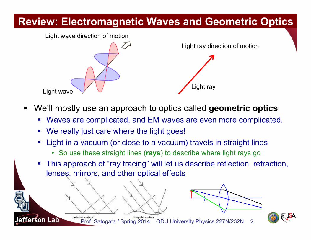
§ We’ll mostly use an approach to optics called geometric optics § Waves are complicated, and EM waves are even more complicated. § We really just care where the light goes! § Light in a vacuum (or close to a vacuum) travels in straight lines
• So use these straight lines (rays) to describe where light rays go § This approach of “ray tracing” will let us describe reflection, refraction,
lenses, mirrors, and other optical effects
Light wave Light ray
Light wave direction of motion Light ray direction of motion
Prof. Satogata / Spring 2014 ODU University Physics 227N/232N 3
Review: Reflection
§ Let’s start optics with reflection § We’re pretty familiar with reflection!
§ For smooth surfaces, incident and reflected rays have the same angle as measured to the normal to the surface
§ Equal angle reflection is seen in more than just optics • e.g. elastic collisions such as billiards
Incident Light ray
Reflected Light ray
Refracted Light ray
✓reflected = ✓incident
✓incident ✓reflected
Dotted line: normal to surface
Prof. Satogata / Spring 2014 ODU University Physics 227N/232N 4
Review: Reflection and Images
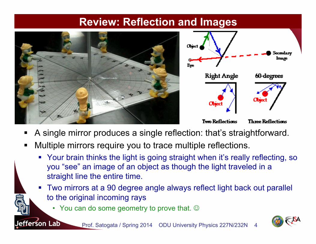
§ A single mirror produces a single reflection: that’s straightforward. § Multiple mirrors require you to trace multiple reflections.
§ Your brain thinks the light is going straight when it’s really reflecting, so you “see” an image of an object as though the light traveled in a straight line the entire time.
§ Two mirrors at a 90 degree angle always reflect light back out parallel to the original incoming rays
• You can do some geometry to prove that. J
Prof. Satogata / Spring 2014 ODU University Physics 227N/232N 5
90 Degree Mirrors and Images
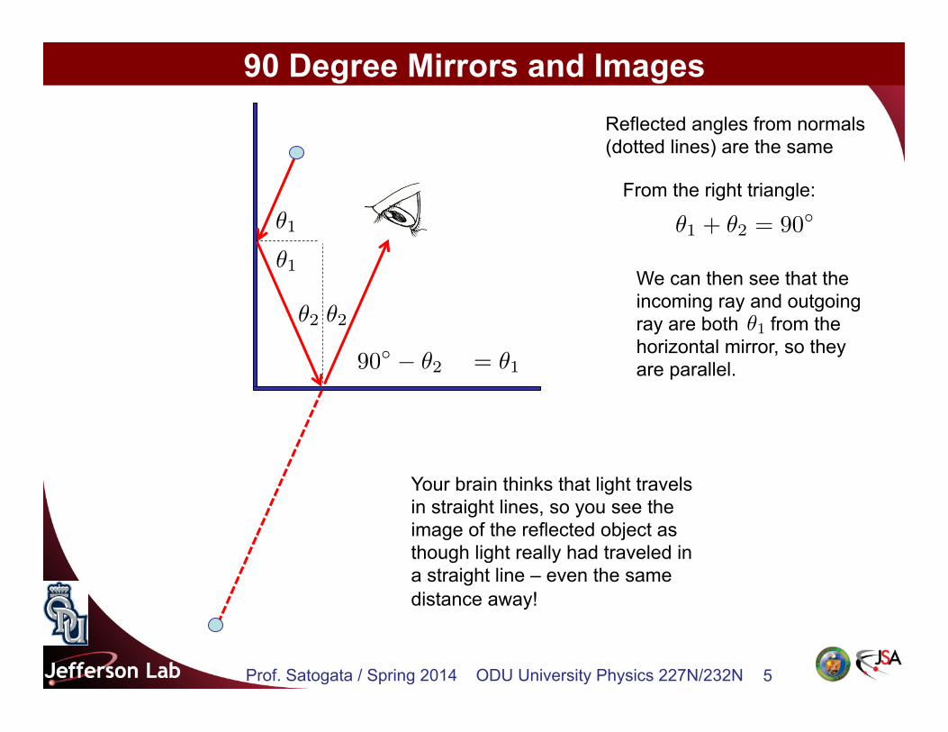
✓1
✓1
✓2 ✓2
✓1 + ✓2 = 90�From the right triangle:
Reflected angles from normals (dotted lines) are the same
90� � ✓2 = ✓1
Your brain thinks that light travels in straight lines, so you see the image of the reflected object as though light really had traveled in a straight line – even the same distance away!
We can then see that the incoming ray and outgoing ray are both from the horizontal mirror, so they are parallel.
✓1
Prof. Satogata / Spring 2014 ODU University Physics 227N/232N 6
How Many Images? In a corner mirror, you see as many images as your brain can “fit” into normal space, as though the reflections really existed. So with a 90 degree mirror, you see four areas in total – one real one and three “virtual” ones. Remember that your brain thinks in visual straight lines, so the locations of the three images that you see here are where your brain thinks the straight line ray of light came from. Note that every intervening mirror (or “wall”) must be a bounce, so here two of the images are only one reflection away, and one image is two reflections away. One reflection
One reflection
Two reflections
Prof. Satogata / Spring 2014 ODU University Physics 227N/232N 7
Other Angles and Images
60�
You can get multiple images from mirrors bent at a smaller angle than 90 degrees. What you see are reflections of the reflections! (And…) Here the green is a single reflection of the light blue “image”.
The smaller the angle, the more images you have until the mirrors are parallel and you have infinite images stretching off into the distance…
This only shows paths for four of the six images!
Prof. Satogata / Spring 2014 ODU University Physics 227N/232N 8
Quick Question
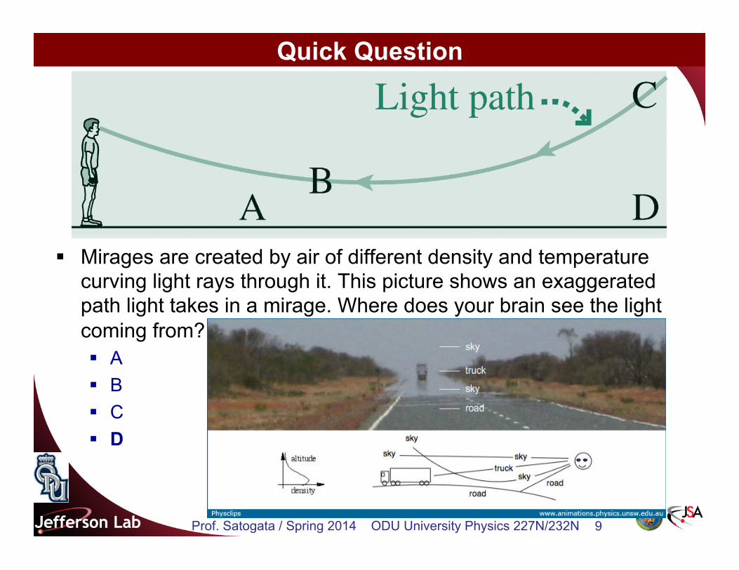
§ Mirages are created by air of different density and temperature curving light rays through it. This picture shows an exaggerated path light takes in a mirage. Where does your brain see the light coming from? § A § B § C § D
Prof. Satogata / Spring 2014 ODU University Physics 227N/232N 9
Quick Question
§ Mirages are created by air of different density and temperature curving light rays through it. This picture shows an exaggerated path light takes in a mirage. Where does your brain see the light coming from? § A § B § C § D
Prof. Satogata / Spring 2014 ODU University Physics 227N/232N 10
Review: Index of Refraction
§ Refraction is the bending of light as it crosses an interface between two different transparent media § Occurs because the apparent light wave speed changes between the
two media. § Index of refraction n:
§ c is the speed of light in a vacuum • So n=1 for a vacuum, n>1 for all other materials
Incident Light ray
Reflected Light ray
Refracted Light ray
✓incident
✓refracted
n ⌘ c
v
Water Crazy
metamaterial
Prof. Satogata / Spring 2014 ODU University Physics 227N/232N 11
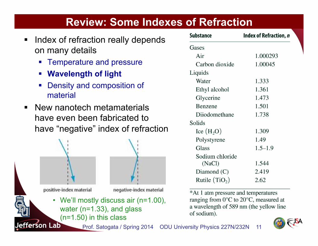
Review: Some Indexes of Refraction § Index of refraction really depends
on many details § Temperature and pressure § Wavelength of light § Density and composition of
material § New nanotech metamaterials
have even been fabricated to have “negative” index of refraction
• We’ll mostly discuss air (n=1.00), water (n=1.33), and glass (n=1.50) in this class
Prof. Satogata / Spring 2014 ODU University Physics 227N/232N 12
Refraction: Snell’s Law § The angles of incidence and refraction and the indexes of
refraction for two materials are related by Snell’s Law:
§ Remember that the angles are measured from the normal to the surface.
§ There is also a reflected light ray from the surface.
n1 sin ✓1 = n2 sin ✓2
Incident Light ray
Reflected Light ray
Refracted Light ray
✓1
✓2
n1
n2
If n1 < n2 then θ1>θ2
If n1 > n2 then θ1<θ2
Prof. Satogata / Spring 2014 ODU University Physics 227N/232N 13
Example
§ You are looking for a ring you accidentally dropped in your pool, so you shine a laser pointer at the pool surface at an angle of 30 degrees from vertical. What is the angle of the laser ray in the pool?
Incident Light ray
Reflected Light ray
Refracted Light ray
✓1
✓2
n1 sin ✓1 = n2 sin ✓2
(1.0) sin(30�) = 1.33 sin ✓2 ) ✓2 = 22�
n1 = 1.0
n2 = 1.33
Prof. Satogata / Spring 2014 ODU University Physics 227N/232N 14
(Refraction Example: Slab Displacement) § Refraction through a plane slab
of glass doesn’t change the direction of rays but displaces them slightly
✓1 = ✓4
✓2 = ✓3
sin(✓1 � ✓2) =x
l
=
x cos ✓2
d
cos ✓2 =
d
l) 1
l=
cos ✓2d
sin(✓1 � ✓2) = sin ✓1 cos ✓2 � cos ✓1 sin ✓2
x
d
= sin ✓1 � cos ✓1 tan ✓2
x
d
= sin ✓1
"1� cos ✓1p
n
2 � sin
2✓1
#
Prof. Satogata / Spring 2014 ODU University Physics 227N/232N 15
– TIR occurs when the incidence angle is greater than the critical angle given by
Total Internal Reflection
§ Total internal reflection (TIR) occurs at the interface from a material with greater refractive index to one with lesser refractive index.
– TIR is used in prism-based reflectors.
– TIR is the basis of optical fibers, guiding light along the fibers that, among other applications, carry data on the interwebz.
sin ✓c =n2
n1
Prof. Satogata / Spring 2014 ODU University Physics 227N/232N 16
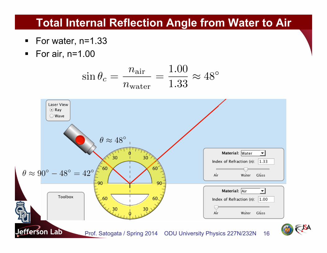
Total Internal Reflection Angle from Water to Air § For water, n=1.33 § For air, n=1.00
sin ✓c =nair
nwater=
1.00
1.33⇡ 48�
✓ ⇡ 48�
✓ ⇡ 90� � 48� = 42�
Prof. Satogata / Spring 2014 ODU University Physics 227N/232N 17
Prof. Satogata / Spring 2014 ODU University Physics 227N/232N 18
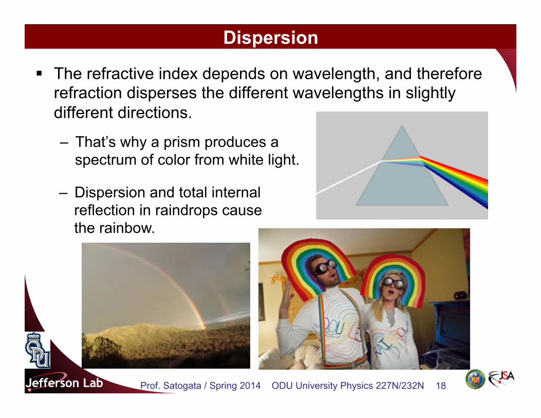
Dispersion
§ The refractive index depends on wavelength, and therefore refraction disperses the different wavelengths in slightly different directions.
– That’s why a prism produces a spectrum of color from white light.
– Dispersion and total internal reflection in raindrops cause the rainbow.
Prof. Satogata / Spring 2014 ODU University Physics 227N/232N 19
Dispersion: Rainbows
§ This reflection and dispersion is why rainbows appear with the sun behind you, and at a certain particular angle in the sky.
Prof. Satogata / Spring 2014 ODU University Physics 227N/232N 20
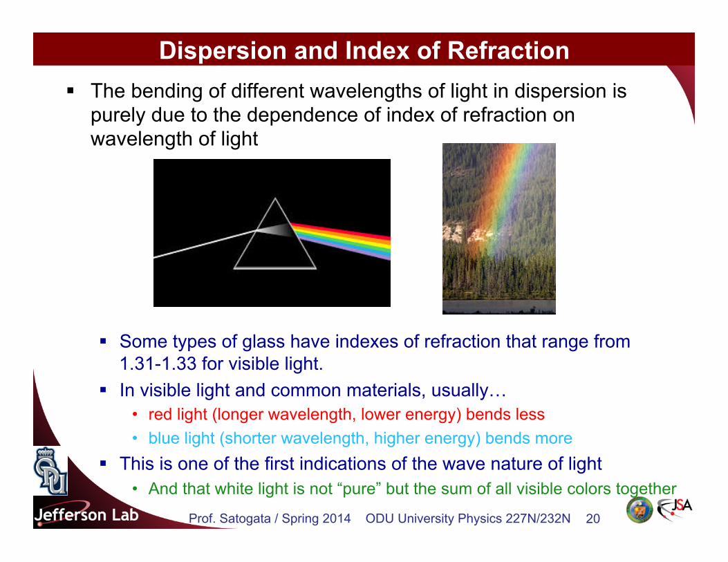
Dispersion and Index of Refraction § The bending of different wavelengths of light in dispersion is
purely due to the dependence of index of refraction on wavelength of light
§ Some types of glass have indexes of refraction that range from
1.31-1.33 for visible light. § In visible light and common materials, usually…
• red light (longer wavelength, lower energy) bends less • blue light (shorter wavelength, higher energy) bends more
§ This is one of the first indications of the wave nature of light • And that white light is not “pure” but the sum of all visible colors together
Prof. Satogata / Spring 2014 ODU University Physics 227N/232N 21
xkcd: Dorm Poster (part 1)
Prof. Satogata / Spring 2014 ODU University Physics 227N/232N 22
xkcd: Dorm Poster (part 2)
http://xkcd.com/964/
This is an example of an optical system called an achromat
Prof. Satogata / Spring 2014 ODU University Physics 227N/232N 23
Dispersion and Spectra
§ Dispersion provided the first insights into the atomic and subatomic nature of material § “White” light (e.g. sunlight) really has dark absorption lines
• Correspond to absorption of certain light frequencies by gases/plasmas § Light from heating or burning different substances shows different
emission lines § Spectroscopy has a myriad of uses on its own
• Ranging from composition analysis to expansion of the universe
Hydrogen lines
Prof. Satogata / Spring 2014 ODU University Physics 227N/232N 24
Prisms and Bending Light
§ Prisms nicely bend light twice § Once at each interface between materials
§ What happens if we stack two prisms on top of each other? § Two thin prisms will take two incoming parallel light ray (like those from
the sun) and make them meet at a point § If we make the surfaces of the prisms curved instead of straight,
maybe we can make all the incoming rays meet at a point § This brings us to reflection and refraction with curved surfaces: lenses
• Let’s do this with curved mirrors first
Prof. Satogata / Spring 2014 ODU University Physics 227N/232N 25
Parabolic and Spherical Mirrors
§ A parabolic mirror focuses rays parallel to the mirror axis to a common focal point.
– A portion of a sphere is a good approximation to a parabola.
• Then the focal point is at half the sphere’s radius.
– In the paraxial approximation, we assume that all rays are nearly parallel to the mirror axis.
– Parabolic mirrors are used as light and energy concentrators
• Solar energy applications • Fire starters
Prof. Satogata / Spring 2014 ODU University Physics 227N/232N 26
(1) A ray parallel to the mirror axis reflects through the focal point.
(2) A ray passing through the focal point reflects parallel to the axis.
(3) A ray striking the center of the mirror reflects symmetrically about the mirror axis.
(4) A ray through the center of curvature of the mirror returns on itself.
Ray Tracing with Curved Mirrors
§ The image formed in a curved mirror can be found using any two of four special light rays:
CF
C: Center of curvature (center of the semicircular mirror) F: Focal point of mirror
Prof. Satogata / Spring 2014 ODU University Physics 227N/232N 27
Image Formation with Curved Mirrors
§ Concave mirrors can form either real or virtual images. § If the object is beyond the center of curvature, the image is real,
inverted, and reduced in size. § If the object is between the center of curvature and the focal point, the
image is real, inverted, and enlarged. § If the object is closer to the mirror than the focal point, the image is
virtual, upright, and enlarged. § The diagram below uses rays (1) and (2) of the previous slide to show
this point.
Prof. Satogata / Spring 2014 ODU University Physics 227N/232N 28
Convex Mirrors
§ Convex mirrors can form only virtual images. § The image is always upright and reduced in size.
Prof. Satogata / Spring 2014 ODU University Physics 227N/232N 29
§ Analysis using similar triangles yields the mirror equation, relating object distance s, image distance s', and the focal length f:
§ The image magnification M is the negative ratio of image distance s' to object distance s:
The Mirror Equation
1
s+
1
s0=
1
f
M =h0
h= �s0
s
Prof. Satogata / Spring 2014 ODU University Physics 227N/232N 30
Sign Conventions for Mirrors § The mirror equation describes all possible cases of image
formation, according to the following sign conventions: