96
NORTHEASTERN UNIVERSITY University Student Launch Initiative 2017-2018 Critical Design Review January 12, 2018

NORTHEASTERN
UNIVERSITY University Student Launch Initiative
2017-2018
Critical Design Review
January 12, 2018

Northeastern University 2017-2018 Student Launch Critical Design Review 1
Table of Contents 1. Team Summary ........................................................................................................................... 3
1.1. Team Summary ................................................................................................................ 3
1.2 Launch Vehicle Summary ................................................................................................ 3
1.3 Payload Summary ............................................................................................................ 3
1.4. Changes Made Since PDR ................................................................................................... 4
1.4.1. Changes Made to Vehicle Criteria ................................................................................. 4
1.4.2. Changes Made to Payload Criteria ................................................................................ 4
1.4.3. Changes Made to Project Plan ....................................................................................... 4
2. Vehicle Criteria ........................................................................................................................... 5
2.1. Design and Verification of Launch Vehicle ......................................................................... 5
2.1.1. Flight Reliability and Confidence .................................................................................. 5
2.1.2 Design Alternatives from PDR ....................................................................................... 5
2.1.3 Computer Aided Design (CAD) Drawings ..................................................................... 7
2.1.4. Discuss the Integrity of Design ...................................................................................... 9
2.1.3. Justification for material selection, dimensioning, component placement, and other
unique design aspects ............................................................................................................. 12
2.2. Subscale Flight Results ...................................................................................................... 14
2.2.1. Subscale Flight Results ................................................................................................ 14
2.2.2. Perform an Analysis of the Subscale Flight ................................................................. 18
2.2.3. Impact of Subscale Flight Data on Full Scale Launch Vehicle ................................... 22
2.3. Recovery Subsystem .......................................................................................................... 23
2.4. Mission Performance Predictions ....................................................................................... 30
3. Safety ........................................................................................................................................ 36
3.1. Launch Concerns and Operation Procedures ..................................................................... 36
3.2. Safety and Environment (Vehicle and Payload) ................................................................ 40
Likelihood Definitions ........................................................................................................... 54
Severity Definitions ............................................................................................................... 54
Environmental Concerns ........................................................................................................ 55
Table 3.2.5 : Environmental Concerns ...................................................................................... 55
4. Payload Criteria ........................................................................................................................ 57
4.1. Design of Payload Equipment ............................................................................................ 57
4.1.1. Wheels.......................................................................................................................... 57
4.1.2. Ejection ........................................................................................................................ 58
4.1.3. Solar Panel Deployment .............................................................................................. 59
4.2. System Level Design Review ............................................................................................. 59
4.2.1. Electronics.................................................................................................................... 59
4.2.2. Solar Panel ................................................................................................................... 60
4.2.2. Solar Panel ................................................................................................................... 60
4.2.3. Wheels.......................................................................................................................... 60
4.2.3. Payload Ejection System.............................................................................................. 60
4.3. Drawings and Specifications for Components and Assembly ........................................... 60
4.4. Payload Component Interaction Description ..................................................................... 64

Northeastern University 2017-2018 Student Launch Critical Design Review 2
4.4.1. Payload Component Interaction Overview .................................................................. 64
4.4.2. NUFR Component Interaction ..................................................................................... 64
4.4.3. PES Component Interaction ......................................................................................... 67
4.5. Payload Integration Plan .................................................................................................... 67
4.6. Demonstration of Payload Design Completion .................................................................. 68
4.7. Payload Electrical Drawings and Dimensions ................................................................... 70
4.8. Payload Block Diagrams .................................................................................................... 72
4.9. Payload Battery and Power Consumption .......................................................................... 74
4.10. Switch and Indicator Wattage and Location .................................................................... 74
4.11. Payload Justification ......................................................................................................... 76
5. Project Plan ............................................................................................................................... 78
5.1. Testing ................................................................................................................................ 78
5.1.1. Payload Tests ............................................................................................................... 78
5.1.2. Rover Test Plans .......................................................................................................... 78
5.2. Requirements Compliance ................................................................................................. 80
5.3. Budgeting and Timeline ..................................................................................................... 92

Northeastern University 2017-2018 Student Launch Critical Design Review 3
1. Team Summary
1.1. Team Summary Team name: NU Frontiers Mailing Address: Northeastern University, 267 Snell Engineering, Boston, MA 02115 Mentor: Robert DeHate Certification Level: L3 Nar/TRA #75198/TAP 9956
1.2 Launch Vehicle Summary The Launch Vehicle has been designed to propel itself and the payload secured inside to an apogee of
5,303 feet. The Launch Vehicle will be made of 4 independent sections (Nose Cone, Payload, Lower
Avionics Bay, and Booster) that will separate during flight events controlled from two avionics bays.
Both avionics bays will contain StratoLogger CF altimeters while the lower avionics bay also will also
contain an XBEE Pro XSC (S3) GPS. Power to the avionics bays will be supplied by 9V batteries, with
each altimeter using a dedicated battery. At apogee, the Lower Avionics Bay and the Booster section will
separate from each other while remaining tethered, deploying a 48 inch drogue parachute. At an altitude
of 800 feet, two events will separate the Launch Vehicle into four independent sections. The Nose Cone
section and the Payload section will be tethered together and will descend on a 72 inch main elliptical
parachute. The Lower Avionics Bay and the Booster will be tethered together and will descend using the
previously deployed drogue parachute and another 72 inch elliptical main parachute. The length of the
Launch Vehicle is 148 inches with an outer diameter of 6.17 inches. The Launch Vehicle, including the
loaded motor, will have a mass of 47.4 pounds, and will be propelled by a Cesaroni L1115 Classic
reloadable motor. The Launch Vehicle will be launching off of a 12 foot 1515 rail.
1.3 Payload Summary NU-FRONTIERS The design experiment chosen was Option 2, the deployable rover. A custom rover and deployment
mechanism has been designed to interface with the launch vehicle. The goal of the experiment is to have
the payload secured in the launch vehicle payload bay throughout the flight and remain safely
encapsulated until the end of the flight path. Once the payload section is safely and successfully on the
ground, the rover deployment method will be activated. The deployment method will utilize a custom
pneumatic piston that will guide the rover along linear bearings until the rover has been fully released
from the launch vehicle body tube. Once the rover is fully deployed, the rover onboard electronics will
measure and record position from the starting point and chassis orientation. The motors will drive the two
main wheels and one supporting wheel to a distance of 5 feet from the landing location, overcoming any
obstacles in the terrain. Onboard electronics will sense if there is an obstacle obstruction the rover
trajectory and navigate a new path. When the rover reaches 5 feet, the custom program logic will
autonomously stop the driving motion. At this point, a servo motor will initiate the foldable solar panel
deployment by means of the rotating fan method. The solar energy collectors will start in a folded and
enclosed position within the rover casing and will be expanded to have panels from 0 to 180 degrees for
Northeastern University 2017-2018 Student Launch Critical Design Review 4
an increase in surface area. The solar panels will be connected to the onboard electronics bay and when
power is generated an indicator light will blink.
1.4. Changes Made Since PDR
1.4.1. Changes Made to Vehicle Criteria
The most significant changes to the Launch Vehicle between the Preliminary Design Review and
the Critical Design Review include revised mass estimates, a relocation of the payload in the
rocket, changes in the recovery system, and a different motor selection. The Launch Vehicle will
still consist of four sections: the Nose Cone, Payload, Lower Avionics Bay, and Booster sections.
At PDR, the Nose Cone section was planned to separate at 800 feet from the remainder of the
Launch Vehicle and fall independently. This has been changed as the Payload section will now
also separate with the Nose Cone section at 800 feet. This allows the payload to be deployed on
the downwards facing end of section instead of the upwards facing end. The final concept of operations is that, at apogee, the drogue parachute will be deployed through
separation of the Booster and Lower Avionics Bay sections. At 800 feet, two events will occur.
The first event will separate the Nose Cone and Payload sections, deploying a 72 inch main
elliptical parachute that tethers these two sections together. Very shortly after, a second event will
separate the payload and lower avionics sections, releasing another 72 inch main elliptical
parachute tethered to the Lower Avionics Bay and Booster sections. In order to allow the launch vehicle to be assembled more simply, the airframe of the Lower
Avionics Bay section splits in two. The Lower Avionics Bay will now be housed in a 12 inch
section of coupler and will be set screwed in the center of the two split airframe pieces. This will
make the installation of the lower avionics bay much easier as the assembler does not have to
reach their arm down the airframe. With the addition of another coupler tube and a heavier
payload estimate, mass estimation of the Launch Vehicle has increased since PDR leading to a
change in motor selection. The new selected motor is the Cesaroni L1115 Classic reloadable
motor, bringing the Launch Vehicle to a new estimated 5,302 feet. The final launch rail selection
will be a twelve foot 1515 rail. 1.4.2. Changes Made to Payload Criteria
No major design changes were made to the payload since PDR. The design has been refined and
the specifics such as which motors, servos, and electronics would be used were figured out. The
initial concept of a two wheeled rover with a folding counter torque tail was maintained and the
layout was adjusted to maximize usable space within the chassis.
1.4.3. Changes Made to Project Plan
No major changes have been made to our project plan. We have added a great deal of detail with
regard to funding and travel plans. We are on track with our timeline and have multiple potential
dates for full scale launches.

Northeastern University 2017-2018 Student Launch Critical Design Review 5
2. Vehicle Criteria
2.1. Design and Verification of Launch Vehicle
2.1.1. Flight Reliability and Confidence
The mission is to construct a Launch Vehicle capable of sending the Payload to an
apogee of 5,374 feet. The Launch Vehicle will then split into two subsections and use a
dual-deploy parachute system to land safely back on the ground. The Booster Stage will
split into the Lower Avionics Bay Section and the Booster Section when the main
parachute is deployed at 800 feet. The Payload Section will split into the Nose Cone
Section and Payload Section at 800 feet as well. For the mission to be successful there
must be minimal damage to the vehicle when the four subsections land. The vehicle must
also:
Reach an apogee of 5,280 feet
Be able to sit armed on the launch pad for 1 hour while remaining functional
Have a total impulse of no more than 5,120 Newton-seconds
Exit the launch rail with:
o A minimum static stability margin of 2.0 calibers of stability
o A minimum velocity of 52 feet per seconds
Deploy drogue parachute at apogee
Separate into the Booster Stage and the Payload Section at apogee and remain tethered
together
Successfully deploy a 48 inch diameter drogue parachute out of the Booster Stage after
initial separation, without the parachute tangling with the other section’s parachute
Booster Section separate into Payload Section, Lower Avionics Bay Section and Booster
Section that are tethered together also at 800 feet
Nose Cone Section separate from Payload Section at 800 feet and deploy 72 inch
parachute
Deploy a 72 inch elliptical main parachute that is connected to the two booster
subsections that are tethered together, slowing the velocity of the sections from 57.81 feet
per second to a final speed of 19.62 feet per second
At landing Launch Vehicle must:
o Sustain minimal damage to payload when landing
o Land in a 2500 foot radius from launch pad
o Land such that the launch vehicle can immediately launch again with minimal to
no repairs
o Safely house the electronics bay for data recovery
o Land at a kinetic energy no greater than 75 ft-lb
2.1.2 Design Alternatives from PDR
Nose Cone:
The design alternatives considered for the nose cone were all material alternatives. The
two main options that were being decided between were fiberglass and carbon fiber.
Northeastern University 2017-2018 Student Launch Critical Design Review 6
Fiberglass was chosen as the leading design because it is a tougher material than carbon
fiber. This means that it can endure more than carbon fiber before breaking. Fiberglass
also is not conductive and is radiolucent, meaning the material allows radiation to pass
through its walls which is especially helpful for allowing signals to pass to and from the
Launch Vehicle. This allows the altimeters to send the altitude data back to base.
Additionally, fiberglass is nearly half the price of carbon fiber and the carbon fiber would
not have been able to be machined by the team. Taking all of this into account the Nose
Cone will be made of fiberglass.
Payload:
The Payload section of the Launch Vehicle needs to house the rover payload. As with any
section of the Launch Vehicle, the material that comprises the body tube is crucial, and
difficult to decide upon. The first main alternative selection was the decision to use
carbon fiber instead of Blue Tube. The second decision was how to attach the parachute
to the Launch Vehicle.
As with other sections of the Launch Vehicle, fiberglass was the material ultimately
chosen. The other options that were considered were Blue Tube and carbon fiber. Blue
Tube was ruled out because it is not as durable as fiberglass and does not handle rough
weather conditions well. Carbon fiber was determined to be too expensive and difficult to
work with, so it was also decided against. In the end, fiberglass is the best choice for the
body tube of the Payload section because it is durable, inexpensive, and easy to work
with.
The attachment method for the parachute to the Launch Vehicle needs to be able to
ensure that the cords do not tangle during deployment. If the parachute cords were to
tangle during the separation, it would cause the parachute not to deploy and potentially
create a safety hazard while also harming the Launch Vehicle. The options for the
attachment method are an eye bolt, a U-bolt or a swivel hoist ring. The swivel hoist ring
was decided as the best option because it will ensure that the cords will be able to move
so would not tangle. The parachute will be connected to the aft bulkhead via a ¼-20
swivel hoist ring.
Booster Section:
The Booster Section of the Launch Vehicle will hold the motor. This means that the
section needs to be sturdy. The Booster Section is also where the fins are attached,
creating another challenge for design. The Motor Section will also use fiberglass with
carbon fiber and blue tube as the possible alternatives explored. The four fins will be a
trapezoidal shape rather than a triangular or elliptical shape.
As with other sections of the Launch Vehicle, fiberglass was ultimately chosen as the
material while Blue Tube and carbon fiber were considered. Blue Tube was ruled out
because it is not as durable as fiberglass and it does not last in rough weather conditions.
Carbon fiber was determined to be too expensive and difficult to work with, so it was
also decided against. In the end, fiberglass is the best choice for the body tube of the
Booster section because it is durable, inexpensive, and easy to work with.
Northeastern University 2017-2018 Student Launch Critical Design Review 7
Another alternative in the Booster section was the number of fins used. In the
OpenRocket simulation software, when the Launch Vehicle was tested with 3 fins, the
stability of the rocket was greatly reduced to the point that the design would not work.
Because of the stability issue, the number of fins on the Launch Vehicle was increased to
four fins. These fins increased the stability of the Launch Vehicle and allowed it to
function properly.
In addition to number of fins, both triangular and elliptical shapes were considered for the
fins, however both were decided against for different reasons. The triangular design was
decided against due to the fact that the Launch Vehicle will be colliding with the ground,
and the triangular design is not structurally sound enough and has a tendency to break.
Elliptical shaped fins were also decided against due to their increased difficulty in
machining. Trapezoidal shaped fins avoid both of these problems because they will be
less likely to break during landing, and the straight lines allow easy fabrication.
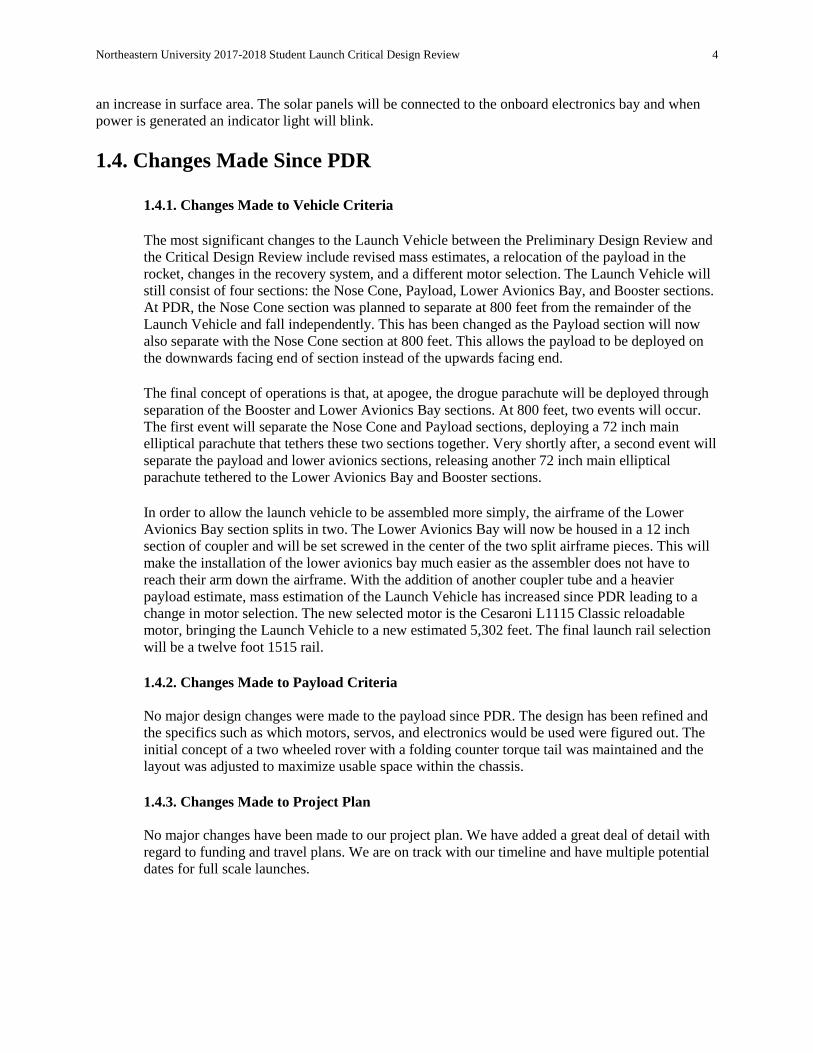
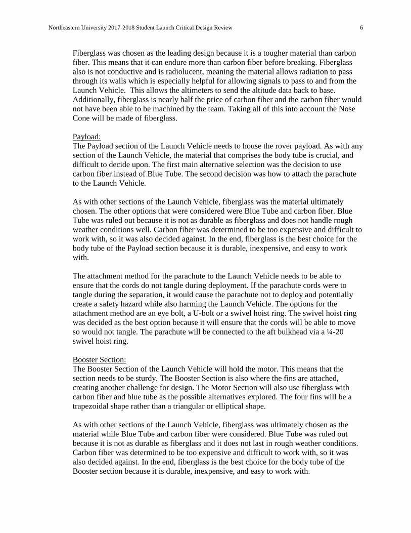
2.1.3 Computer Aided Design (CAD) Drawings
Figure 2.1.3.1 - OpenRocket Design of the Launch Vehicle
Figure 2.1.3.2 - CAD Dimensional Drawing of Launch Vehicle

Northeastern University 2017-2018 Student Launch Critical Design Review 8
Figure 2.1.3.3 - CAD Dimensional Drawing of Nose Cone Section
Figure 2.1.3.4 - CAD Dimensional Drawing of Payload Section

Northeastern University 2017-2018 Student Launch Critical Design Review 9
Figure 2.1.3.5 - CAD Dimensional Drawing of Avionics Bay Section
Figure 2.1.3.6 - CAD Dimensional Drawing of Booster Section
2.1.4. Discuss the Integrity of Design
When deciding the shape of the fin, it is crucial to consider the drag properties of the
various shapes. An ideal design for a fin would minimize drag while ensuring stability
and the lift of the Launch Vehicle. The fins also must be sturdy enough to withstand the
Northeastern University 2017-2018 Student Launch Critical Design Review 10
landing of the motor section of the Launch Vehicle. If the fins are not in a durable enough
they will break when landing. During the design of the fins, trapezoidal, elliptical, and
triangular fins were considered. The trapezoidal fins used provided lower drag than
elliptical fins, allowing the Launch Vehicle to reach its highest potential. In addition, the
tips of the four trapezoidal fins are effective at creating lift and provide stability in cases
where the path of the Launch Vehicle is disturbed.
Throughout the initial design process, great care was taken in deciding the materials to
make up the structural elements of the Launch Vehicle. A structure element can be
considered a load bearing element at least point throughout out the flight mission. The
main structural elements that were taken into consideration were the airframe, coupler,
bulkheads, fins, and the electronics bays. The airframe and coupler will be made of
composite G12 fiberglass from Mad Cow Rocketry. This material was chosen due to its
strength and stiffness as compared to alternatives such as Blue Tube. The G12 fiberglass
also has good impact resistance for landing on harder surfaces, for increased flight
mission success and re-launchability. The nose cone will also be made from G12
fiberglass from Mad Cow Rocketry for the same structural reasons. A similar material for
the fins was chosen as the fins of the rocket can often break on landings. G10 Fiberglass
was chosen for the fin material as it is a lightweight and thin fin material. While plywood
fins for the Northeastern University AIAA Student Chapter have been popular and
successful in the past, fins made of composite wood are susceptible to water damage, and
are often thicker with a rougher surface finish. G12 has similar mechanical properties to
G10 fiberglass, but also features more electrical resistance.
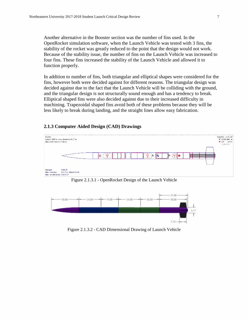
Table 2.1.4.1. - G10 Fiberglass Material Properties
Density 0.0650 lb/in3
Tensile Strength at Break 38000 psi Crosswise
45000 psi Lengthwise
Flexural Strength 65000 psi Crosswise
75000 psi Lengthwise
One of the most important components to design for is the bulkheads and centering rings.
The bulkheads receive a variety of tensile and compressive forces and large impulses
from ejection charges and parachute deployments. Centering rings transfer the forces
from the motor to the airframe on launch and also experience large force loads. The
selected material for is laser cut ¼ inch thick Mil-P-6070 aircraft mahogany plywood,
whose specifications are found in Table 2.1.4.2.

Northeastern University 2017-2018 Student Launch Critical Design Review 11
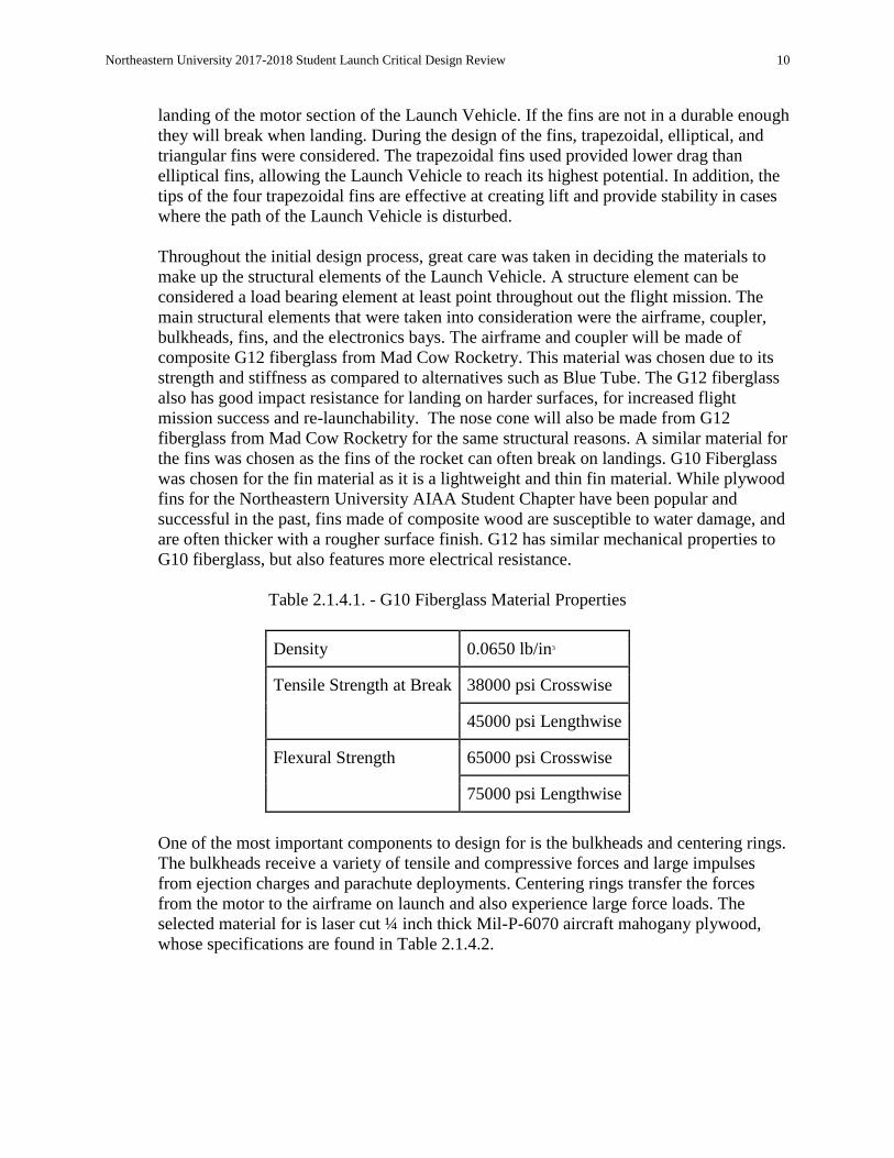
Table 2.1.4.2. MIL-P-6070 Aircraft Mahogany Plywood Material Properties
Material Type Laminate (Orthotropic)
Young's Modulus (Longitudinal) 1.39 - 1.7 x 10⁶ psi
Young’s Modulus (Transverse) 0.119 - 0.133 x 10⁶ psi
Tensile Strength (Longitudinal) 8.96 - 10.9 ksi
Tensile Strength (Transverse) 0.479 - 0.595 ksi
Shear Strength (Longitudinal) 1.35 - 1.65 ksi
Shear Strength (Transverse) 4.06 - 4.95 ksi
Flexural Strength (Longitudinal) 9.63 - 11.8 ksi
Flexural Strength (Transverse) 0.479 - 595 ksi
While typically not load bearing, the avionics bay can experience large forces throughout
the flight and should be designed with this in mind. The avionics bays will be made out
of ABS plastic, which has a higher melting point than PLA. Although they will be 3D
printed, which could reduce structural integrity; it provides freedom in the design of the
electronics bay as a whole. In addition, 3D printed, ABS electronics bays have been
proven to work in the past for Northeastern’s AIAA chapter
The motor being used is a 75 millimeter 4 grain Cesaroni reloadable motor type. The
reusable casing will be loaded into the aft end of the rocket into a 75 millimeter Blue
Tube motor mount tube. The motor casing will be inserted in its entirety into the Launch
Vehicle and secured into the motor mount tube with a motor retainer made of 6061-T6
aluminum with a corrosion resistant black anodize coating. The selected motor retainer is
produced by Aero Pack and has been shown to be successful in previous Northeastern
University AIAA Student Chapter launches. This is a very popular method of motor
retention due to its ease of use, and ability to quickly secure or remove a loaded motor
casing. The Aero Pack motor retainer will be secured to the Launch Vehicle using the
adhesive JB Weld. The motor retainer secures the motor in the axial direction and
distributes the thrust load on the rocket through the motor mount tube and centering
rings. The motor mount tube secures the motor radially and aligns the motor axially to the
airframe. The friction fit between the motor casing and the motor mount tube and the
motor retainer fixes the casing from rotating during the flight mission.
Northeastern University 2017-2018 Student Launch Critical Design Review 12
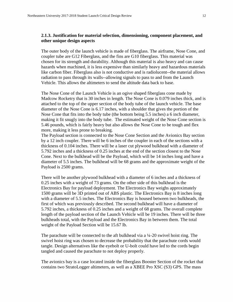
2.1.3. Justification for material selection, dimensioning, component placement, and
other unique design aspects
The outer body of the launch vehicle is made of fiberglass. The airframe, Nose Cone, and
coupler tube are G12 Fiberglass, and the fins are G10 fiberglass. This material was
chosen for its strength and durability. Although this material is also heavy and can cause
hazards when machined, it is less expensive than similarly heavy and hazardous materials
like carbon fiber. Fiberglass also is not conductive and is radiolucent--the material allows
radiation to pass through its walls--allowing signals to pass to and from the Launch
Vehicle. This allows the altimeters to send the altitude data back to base.
The Nose Cone of the Launch Vehicle is an ogive shaped fiberglass cone made by
Madcow Rocketry that is 30 inches in length. The Nose Cone is 0.079 inches thick, and is
attached to the top of the upper section of the body tube of the launch vehicle. The base
diameter of the Nose Cone is 6.17 inches, with a shoulder that gives the portion of the
Nose Cone that fits into the body tube (the bottom being 5.5 inches) a 6 inch diameter,
making it fit snugly into the body tube. The estimated weight of the Nose Cone section is
5.46 pounds, which is fairly heavy but also allows the Nose Cone to be tough and flex
more, making it less prone to breaking.
The Payload section is connected to the Nose Cone Section and the Avionics Bay section
by a 12 inch coupler. There will be 6 inches of the coupler in each of the sections with a
thickness of 0.104 inches. There will be a laser cut plywood bulkhead with a diameter of
5.792 inches and a thickness of 0.25 inches at the end of the section closest to the Nose
Cone. Next to the bulkhead will be the Payload, which will be 14 inches long and have a
diameter of 5.5 inches. The bulkhead will be 68 grams and the approximate weight of the
Payload is 2500 grams.
There will be another plywood bulkhead with a diameter of 6 inches and a thickness of
0.25 inches with a weight of 73 grams. On the other side of this bulkhead is the
Electronics Bay for payload deployment. The Electronics Bay weighs approximately
1500 grams will be 3D printed out of ABS plastic. The Electronics Bay is 8 inches long
with a diameter of 5.5 inches. The Electronics Bay is housed between two bulkheads, the
first of which was previously described. The second bulkhead will have a diameter of
5.792 inches, a thickness of 0.25 inches and a weight of 68 grams. The overall complete
length of the payload section of the Launch Vehicle will be 19 inches. There will be three
bulkheads total, with the Payload and the Electronics Bay in between them. The total
weight of the Payload Section will be 15.67 lb.
The parachute will be connected to the aft bulkhead via a ¼-20 swivel hoist ring. The
swivel hoist ring was chosen to decrease the probability that the parachute cords would
tangle. Design alternatives like the eyebolt or U-bolt could have led to the cords begin
tangled and caused the parachute to not deploy properly.
The avionics bay is a case located inside the fiberglass Booster Section of the rocket that
contains two StratoLogger altimeters, as well as a XBEE Pro XSC (S3) GPS. The mass
Northeastern University 2017-2018 Student Launch Critical Design Review 13
of the avionics bay is 750 grams. This bay is between two bulkheads of diameter 6 inches
and thickness 0.25 inches. The two bulkheads are 11 inches apart from each other. There
are two blast caps on each bulkhead, on the side facing out and away from the Electronics
Bay. There are also two terminal blocks on each side of the bulkhead. There are ⅜-16
inch forged eye bolts on each side of the bulkheads. The total mass of the lower avionics
bay section is 8.97 lbs.
The Booster Section is 36 inches long and has an inner diameter of 6 inches and outer
diameter of 6.17 inches. The material of the Booster Section is made of fiberglass. The
Booster Section also contains an inner tube with an outer diameter 3.1 inches. This inner
tube is made from Blue Tube and is attached to the body tube with four 0.25 inch birch
centering rings placed at 0, 8.25, 14.25, and 21 inches from the bottom of the rocket. The
section ends with a 12 coupler tube connecting the two lowest body tube sections. At the
end of the coupler tube, a 0.25 inch birch bulkhead separates marks the end of the booster
section. On this bulkhead, a half-inch 20 swivel hoist ring is in place to anchor the main
parachute to the booster section of the rocket. The estimated mass of the Booster Section
is 7.76 lbs with a loaded motor.
The Booster Section has 4 fiberglass trapezoidal fins. OpenRocket simulations
demonstrated that 4 fins would optimize the stability of the rocket. The trapezoidal design
is simple to machine and is a structurally sound shape for ground impact.
The motor mount of the launch vehicle is 24.25 inches long, has an inner diameter of
54mm inches, and an outer diameter of 3.1 inches. It is composed of Blue Tube. The
subsystem will house the Cesaroni L1115 Classic reloadable motor. Simulations
performed on the open source flight simulation software OpenRocket predict that this
motor will the launch the Launch Vehicle at an altitude of approximately 5302 feet.

Northeastern University 2017-2018 Student Launch Critical Design Review 14
2.2. Subscale Flight Results
2.2.1. Subscale Flight Results
Figure 2.2.1.1

Northeastern University 2017-2018 Student Launch Critical Design Review 15
Figure 2.2.1.2
Figure 2.2.1.3

Northeastern University 2017-2018 Student Launch Critical Design Review 16
Figure 2.2.1.4
The data gathering devices used during test launch were four StratoLogger CF altimeters. The
altimeters were located in the avionics bay and recorded a starting altitude of -1 meters, or -3.28
feet, and an apogee of 705 meters, or 2,313 feet. Thus, the recorded apogee, if the Launch
Vehicle had launched from 0 meters or feet, was 706 meters, or 2,316.28 feet. This is in
comparison to the Open Rocket flight simulation which had a predicted apogee of 2,723 feet. The
graphs of the recorded altitude over time are located above.
Scaling Factors The size of the subscale compared to the full size Launch Vehicle generally followed a ratio of
2:3. The figure below shows the design of the final full scale launch vehicle.
Figure 2.2.1.5
Northeastern University 2017-2018 Student Launch Critical Design Review 17
The inner diameter of the final Launch Vehicle was 6 inches and the inner diameter of the
subscale measured 4 inches. The length of the full scale Launch Vehicle will be 148 inches while
the subscale Launch Vehicle was a length of 108 inches. This deviated from the general rule to
ensure greater stability. The subscale model is located below.
Figure 2.2.1.6
The size changes were made to increase the safety factor of the design when testing the
experimental ejection system for the parachutes. The subscale Launch Vehicle had two
parachutes; a main parachute measured 48 inches and a drogue parachute measured 36 inches.
The full scale Launch Vehicle will include two parachutes; a main parachute measuring 72
inches, following the 2:3 ratio, and a drogue parachute measuring 48 inches. In both models the
drogue parachutes have 0.8 drag coefficients and the main parachutes have 2.2 drag coefficients.
The result of this is that the subscale design can more accurately represent the behavior of the
final design. The stability of the full scale Launch Vehicle was 3.35 caliber, and the stability of
the subscale Launch Vehicle was 1.76 caliber. The stability between both models was intended to
stay relatively constant so that the subscale Launch Vehicle and full scale Launch Vehicle would
behave in similar manners in similar launch conditions.
Launch Day Conditions The launch took place in Church Hill, Maryland on December 16th, 2017. The temperature then
ranged from a low of -5 degrees Celsius to a high of 7 degrees Celsius. There was a cover of
scattered clouds, but no precipitation. The wind speed was recorded at 9 miles per hour on the
ground, so the Launch Vehicle was launched at a 5 degree angle. A simulation using these
conditions can be found below.

Northeastern University 2017-2018 Student Launch Critical Design Review 18
Figure 2.2.1.7
2.2.2. Perform an Analysis of the Subscale Flight
Predicted Flight Model vs. Actual Flight Data
In preparation for the launch of the subscale model of the Launch Vehicle, taking place on
December 16th, the team generated simulation data to predict the successfulness of the launch
utilizing the Open Rocket software. That simulation can be seen below.
Figure 2.2.2.1: Open Rocket Simulation

Northeastern University 2017-2018 Student Launch Critical Design Review 19
In comparison, displayed below is the sub-scale’s flight data in the actual launch as recorded by
one of the Launch Vehicle’s stratologers during flight.
Figure 2.2.2.2: 12/16/17 Flight Data
As displayed in the figures above, the direct apogee of the Launch Vehicle may have been
slightly lower than estimated due to a number of possible factors such as slight differences in
weight, weather patterns, etc. The general path of descent, and velocity throughout its movement
were generally accurate to the simulated data, this can be observed by the similar slopes of the
two graphs. The test launch for the subscale in Church Hill, Maryland had an apogee of 705 meters, or 2,313
feet. The predicted apogee based on the Open Rocket software was 830 meters, or 2723 feet.
Potential causes for the difference in apogee may include weather conditions and launching at a 5
degree angle.
Estimate the drag coefficient of full scale rocket with subscale data. For the full scale rocket, the drag coefficient was estimated utilizing flow similarity. Due to the
parallels in the geometry of both rockets, the streamlines that go along the bodies of the launch
vehicles are also proportionally similar. Using this knowledge combined with the Buckingham Pi
Theorem, which relates fluid density flowing along the launch vehicle (ρ), dynamic viscosity (μ),
characteristic linear dimension (L), and fluid velocity (v), the team is able to define the
corresponding Reynolds number derived in the equation below,
This Reynolds Number is the ratio between inertia force and viscous force, and is able to be
utilized to characterize the flow's behavior, and thereby determine whether it is laminar,
Northeastern University 2017-2018 Student Launch Critical Design Review 20
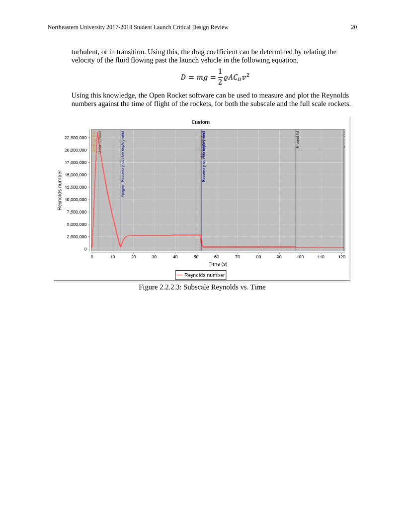
turbulent, or in transition. Using this, the drag coefficient can be determined by relating the
velocity of the fluid flowing past the launch vehicle in the following equation,
Using this knowledge, the Open Rocket software can be used to measure and plot the Reynolds
numbers against the time of flight of the rockets, for both the subscale and the full scale rockets.
Figure 2.2.2.3: Subscale Reynolds vs. Time
Northeastern University 2017-2018 Student Launch Critical Design Review 21
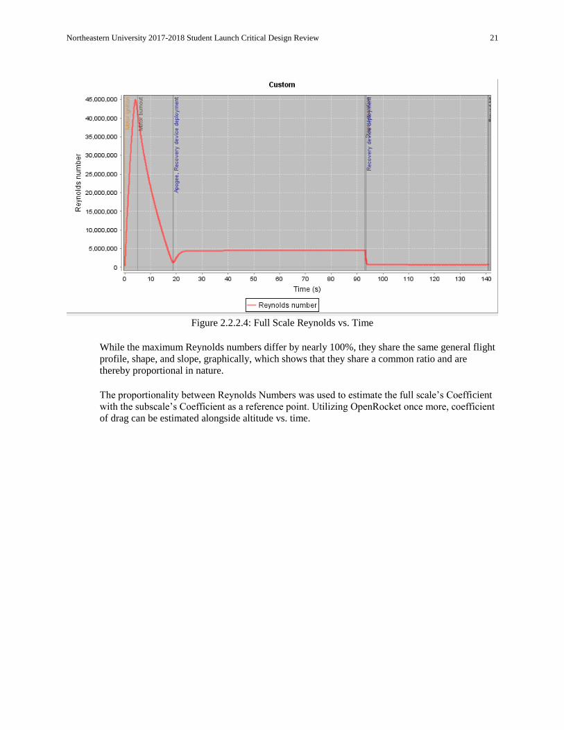
Figure 2.2.2.4: Full Scale Reynolds vs. Time
While the maximum Reynolds numbers differ by nearly 100%, they share the same general flight
profile, shape, and slope, graphically, which shows that they share a common ratio and are
thereby proportional in nature. The proportionality between Reynolds Numbers was used to estimate the full scale’s Coefficient
with the subscale’s Coefficient as a reference point. Utilizing OpenRocket once more, coefficient
of drag can be estimated alongside altitude vs. time.

Northeastern University 2017-2018 Student Launch Critical Design Review 22
Figure 2.2.2.5: Subscale Coefficient of Drag
Focusing on the data pertaining to the drag coefficient leading up to recovery device deployment,
the coefficient of drag is to be estimated an average of roughly 0.604125. With this the coefficient
of drag of the full scale can be estimated to be relatively close.
2.2.3. Impact of Subscale Flight Data on Full Scale Launch Vehicle
Design choices made in the subscale version of the Launch Vehicle have influenced future
decisions that apply to the full scale Launch Vehicle. The general design of the launch vehicle
and recovery systems were reliable and should be implemented into the full scale. However, the
subscale flight data has had a slight impact on the full scale. In the first launch of our subscale
launch vehicle, the ejection charge responsible for splitting the rocket at the junction between the
payload and booster sections deployed, but failed to separate the sections. In the second subscale
launch, this issue was fixed by increasing the charge and using 2 shear pins instead of 4 shear
pins in the coupler between those two sections. This second launch proved this change to be
effective, so it will be utilized in the full scale design. Another change to the full scale design will
be organization of the electronics bays. Wire management needs to be improved for organization
and spatial optimization. In addition, the plastic structure needs to be revised as a result of issues
with battery placement and due to increased space in the full scale. Lastly, due to issues with the
labeling of the different body tube sections, there was confusion with how each section was
oriented with one another. In the full scale, labeling will be more precise and easier to understand
in order to avoid this confusion. Overall we have been able to learn from the subscale. We have
implemented changes and as a result the full scale Launch Vehicle will be better off.
Northeastern University 2017-2018 Student Launch Critical Design Review 23
2.3. Recovery Subsystem
Chose recovery design alternative from PDR
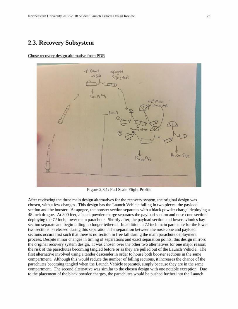
Figure 2.3.1: Full Scale Flight Profile
After reviewing the three main design alternatives for the recovery system, the original design was
chosen, with a few changes. This design has the Launch Vehicle falling in two pieces: the payload
section and the booster. At apogee, the booster section separates with a black powder charge, deploying a
48 inch drogue. At 800 feet, a black powder charge separates the payload section and nose cone section,
deploying the 72 inch, lower main parachute. Shortly after, the payload section and lower avionics bay
section separate and begin falling no longer tethered. In addition, a 72 inch main parachute for the lower
two sections is released during this separation. The separation between the nose cone and payload
sections occurs first such that there is no section in free fall during the main parachute deployment
process. Despite minor changes in timing of separations and exact separation points, this design mirrors
the original recovery system design. It was chosen over the other two alternatives for one major reason;
the risk of the parachutes becoming tangled before or as they are pulled out of the Launch Vehicle. The
first alternative involved using a tender descender in order to house both booster sections in the same
compartment. Although this would reduce the number of falling sections, it increases the chance of the
parachutes becoming tangled when the Launch Vehicle separates, simply because they are in the same
compartment. The second alternative was similar to the chosen design with one notable exception. Due
to the placement of the black powder charges, the parachutes would be pushed further into the Launch
Northeastern University 2017-2018 Student Launch Critical Design Review 24
Vehicle before being jerked out by the separation. Even though this design requires fewer sections of
coupler tube, it greatly increases the chance the parachutes become caught, preventing them from
deploying correctly. Therefore, the third and original design alternative was chosen, as it presented the
least risk of parachute entanglement which would result in failure of the recovery system as a whole. Parachute, harnesses, bulkheads, and attachment hardware
Parachutes
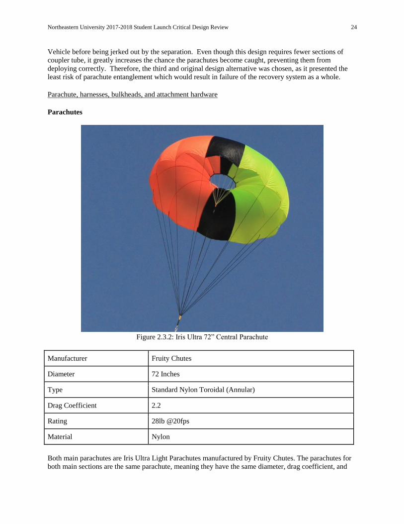
Figure 2.3.2: Iris Ultra 72” Central Parachute
Manufacturer Fruity Chutes
Diameter 72 Inches
Type Standard Nylon Toroidal (Annular)
Drag Coefficient 2.2
Rating 28lb @20fps
Material Nylon
Both main parachutes are Iris Ultra Light Parachutes manufactured by Fruity Chutes. The parachutes for
both main sections are the same parachute, meaning they have the same diameter, drag coefficient, and

Northeastern University 2017-2018 Student Launch Critical Design Review 25
rating. By this metric, both parachutes have a 72 inch diameter, a rating of descent of 20 feet per second
at 28 pounds of weight.
Figure 2.3.3: Drogue Parachute
Manufacturer Sunward Group Ltd
Diameter 48”
Type Octagonal
Drag Coefficient 0.8
Rating 65lb @22fps
Material Nylon
The drogue parachute located in the lower booster main has a 48 inch diameter and unlike the main
parachutes which have toroidal shapes, has an octagonal shape instead. With a lower drag coefficient of
0.8 compared to the main parachutes of 2.2, it is able to maintain a higher rating of 22 feet per second for
65 pounds. Bulkheads The bulkheads featured on the full-scale design of the Launch Vehicle are crafted from ¼ inch birch
plywood, and total to eight throughout the length of the Length Vehicle. All bulkheads have a diameter of
5.787402 inches, save for the bulkhead nearest the nose cone, and the bulkhead nearest the motor section,
which each have a diameter of 5.984252 inches.
Northeastern University 2017-2018 Student Launch Critical Design Review 26
Eyebolt
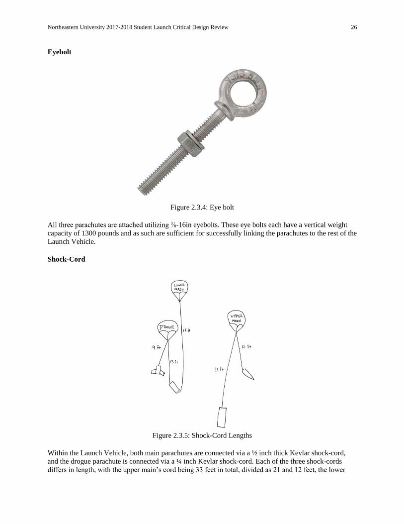
Figure 2.3.4: Eye bolt
All three parachutes are attached utilizing ⅜-16in eyebolts. These eye bolts each have a vertical weight
capacity of 1300 pounds and as such are sufficient for successfully linking the parachutes to the rest of the
Launch Vehicle. Shock-Cord
Figure 2.3.5: Shock-Cord Lengths
Within the Launch Vehicle, both main parachutes are connected via a ½ inch thick Kevlar shock-cord,
and the drogue parachute is connected via a ¼ inch Kevlar shock-cord. Each of the three shock-cords
differs in length, with the upper main’s cord being 33 feet in total, divided as 21 and 12 feet, the lower
Northeastern University 2017-2018 Student Launch Critical Design Review 27
main being 18 feet in total, and the drogue being 22 feet in total, divided as 9 and 13 feet. Each shock
cord is connected via eyebolts, as detailed above.
Electrical Components
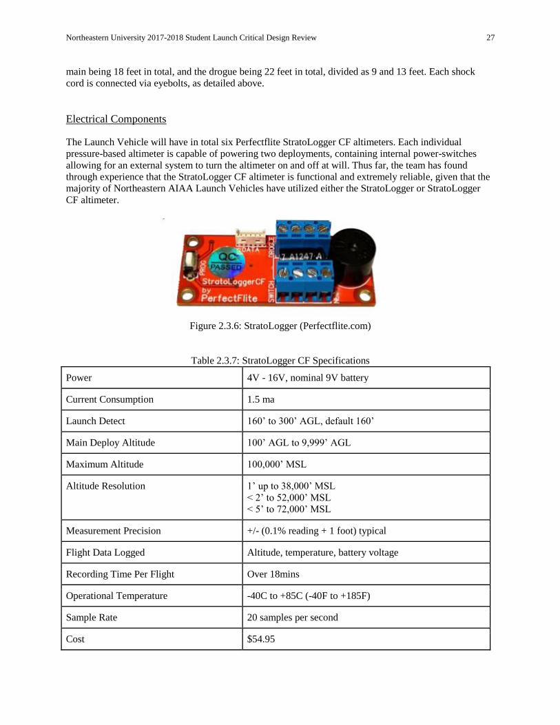
The Launch Vehicle will have in total six Perfectflite StratoLogger CF altimeters. Each individual
pressure-based altimeter is capable of powering two deployments, containing internal power-switches
allowing for an external system to turn the altimeter on and off at will. Thus far, the team has found
through experience that the StratoLogger CF altimeter is functional and extremely reliable, given that the
majority of Northeastern AIAA Launch Vehicles have utilized either the StratoLogger or StratoLogger
CF altimeter.
Figure 2.3.6: StratoLogger (Perfectflite.com)
Table 2.3.7: StratoLogger CF Specifications
Power 4V - 16V, nominal 9V battery
Current Consumption 1.5 ma
Launch Detect 160’ to 300’ AGL, default 160’
Main Deploy Altitude 100’ AGL to 9,999’ AGL
Maximum Altitude 100,000’ MSL
Altitude Resolution 1’ up to 38,000’ MSL < 2’ to 52,000’ MSL < 5’ to 72,000’ MSL
Measurement Precision +/- (0.1% reading + 1 foot) typical
Flight Data Logged Altitude, temperature, battery voltage
Recording Time Per Flight Over 18mins
Operational Temperature -40C to +85C (-40F to +185F)
Sample Rate 20 samples per second
Cost $54.95

Northeastern University 2017-2018 Student Launch Critical Design Review 28
In order to provide the safest recovery of the Launch Vehicle, there needs to be redundancy in the
recovery system. For every ejection event, an e-match will spark and ignite a small black powder charge
to separate the rocket. There will be two Stratologger altimeters responsible for every separation event.
Two Strataloggers will be located in the Lower Avionics Bay for the separation at apogee. There will be
another two Stratologgers in the same Avionics Bay and the Nose Cone Avionics Bay for the two
separation events that occur at 800 feet on the descent. Traditionally, one Stratologger is able to provide
enough power for two ejection events. By having six Stratologgers perform the job that can be performed
by two; we are ensuring that each altimeter will have sufficient current to ignite the e-match and record
data for the entirety of the flight. In terms of power-sources, each Altimeter utilizes a nine volt battery, specifically, the Duracell Quantum
Series 9-Volt Battery. After having compared this battery to several alternatives, including the Energizer
Lithium Battery, the Amazon Brand 9-Volt Batteries, the team determined the Duracell model to be the
best battery. In making this choice, the team considered capacity, battery construction, and internal
resistance. The Duracell was chosen following these specifications, and those mentioned in the below
table:
Figure 2.3.8. : Duracell Quantum 9V
Table 2.3.9. Duracell Quantum 9V Specifications
Manufacturer Duracell
Nominal Voltage 9.6 V
Capacity 4700
Impedance 1.7 ohm
Mass 46 grams

Northeastern University 2017-2018 Student Launch Critical Design Review 29
Figure 2.3.10: Sample Recovery System Circuit Diagram
Figure 2.3.11: XBee PRO S3B
The tracking system used is contained within the payload sections and lower avionics sections of the
launch vehicle and operates at a frequency dependent on the electronic systems. The factors that this
frequency is dependent on include the polling rate of the GPS, the rate at which the Arduino runs the
code, and the rate at which the XBee transmits data. The limiting factor of these processes is the 10Hz
rate at which the GPS polls for new data. Therefore, we will be receiving location updates at a rate of
approximately 10 times per second.

Northeastern University 2017-2018 Student Launch Critical Design Review 30
2.4. Mission Performance Predictions Flight Profile Simulations
Figure 2.4.1: Flight profile simulation.
20 simulation runs on OpenRocket found an expected apogee of 5,303 feet, plus or minus 6 feet.
MATLAB simulations find slightly lower values: 17 s for time to apogee and 4700 ft for apogee.
Table 2.4.2: Component Mass Distribution
Component Mass
Nose Cone Section
Body Tube 1182 g
Ogive Fiberglass Nose Cone 1043 g
Bulkhead 73 g
Nose Cone Avionics Bay 200 g
Shock Cord 3.29 g
Parachute 50.6 g
Payload/Booster Section
Body Tube 936 g
Body Tube 2217 g

Northeastern University 2017-2018 Student Launch Critical Design Review 31
Body tube 1478 g
Bulkhead x3 68 g each
Bulkhead x4 73 g each
Centering ring x4 53.5 g each
Tube coupler x3 697 g each
Shock Cord x2 4.11 g each
Payload Mechanical 2250 g
Payload Deployment Electronics Bay 1000 g
Booster Section Avionics Bay 1000 g
Parachute Booster Main 181 g
Parachute Booster Drogue 81.5 g
Trapezoidal fin set 1066 g
Inner Tube 248 g
Figure 2.4.3: L1115 Thrust Curve.
Northeastern University 2017-2018 Student Launch Critical Design Review 32
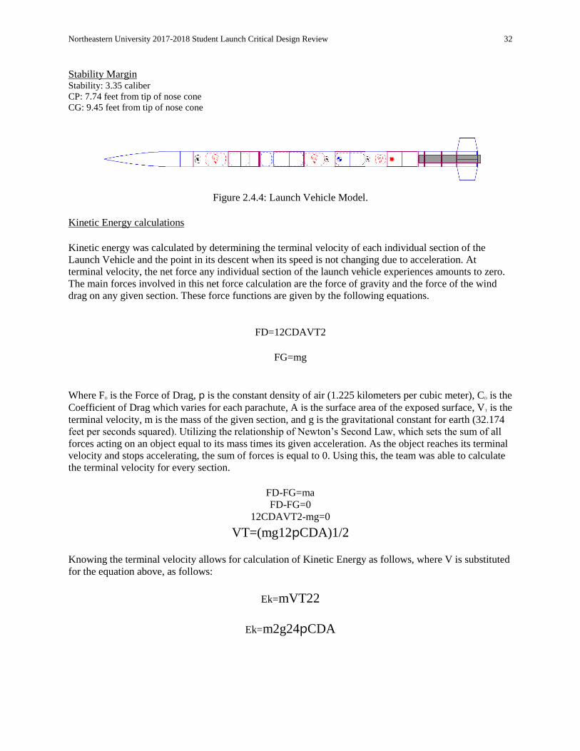
Stability Margin Stability: 3.35 caliber CP: 7.74 feet from tip of nose cone CG: 9.45 feet from tip of nose cone
Figure 2.4.4: Launch Vehicle Model.
Kinetic Energy calculations Kinetic energy was calculated by determining the terminal velocity of each individual section of the
Launch Vehicle and the point in its descent when its speed is not changing due to acceleration. At
terminal velocity, the net force any individual section of the launch vehicle experiences amounts to zero.
The main forces involved in this net force calculation are the force of gravity and the force of the wind
drag on any given section. These force functions are given by the following equations.
FD=12CDAVT2
FG=mg
Where FD is the Force of Drag, ⲣ is the constant density of air (1.225 kilometers per cubic meter), CD is the
Coefficient of Drag which varies for each parachute, A is the surface area of the exposed surface, VT is the
terminal velocity, m is the mass of the given section, and g is the gravitational constant for earth (32.174
feet per seconds squared). Utilizing the relationship of Newton’s Second Law, which sets the sum of all
forces acting on an object equal to its mass times its given acceleration. As the object reaches its terminal
velocity and stops accelerating, the sum of forces is equal to 0. Using this, the team was able to calculate
the terminal velocity for every section.
FD-FG=ma FD-FG=0
12CDAVT2-mg=0
VT=(mg12ⲣCDA)1/2
Knowing the terminal velocity allows for calculation of Kinetic Energy as follows, where V is substituted
for the equation above, as follows:
Ek=mVT22
Ek=m2g24ⲣCDA

Northeastern University 2017-2018 Student Launch Critical Design Review 33
Using the Kinetic Energy equation listed above, the team began calculations based on the relevant
parachute data and section. Because the relevant data for the force of drag in the kinetic energy equation
above was related to the parachutes, the table is organized by parachute instead of section.
Table 2.4.5: Parachute Coefficients and Area
Parachute CD A(in2)
Nose Cone Main 2.2 6840
Drogue 0.8 1564.4
Booster Main 2.2 6840
Given the parachute data and the mass of each section, the team was able to calculate the Kinetic Energy
of the rocket. The data for these calculations are listed in the following table, which is organized by
section, mass, parachute, and Kinetic Energy.
Table 2.4.6: Kinetic Energy Data by Section
Section Mass Total (lb) Parachute Data (CD * A) Kinetic Energy (ft * lb)
Nose-Cone 2.86 Nose Cone Main 21.8
Payload 15.67 Drogue + Booster Main 62.4
Lower Avionics Bay 6.50 Drogue + Booster Main 33.4
Booster 7.75 Drogue + Booster Main 45.8
The team was conscious of the maximum Kinetic Energy for any given section, 75 foot-pounds, and
attempted to obey that constraint. As observed in the table above, all sections stay within this limit.
Wind Drift Calculations Drift due to wind can conservatively be calculated by simulating a flight profile to find flight time and
multiplying by the wind speed. Under a nominal flight configuration, the rocket would experience the
following drifts:

Northeastern University 2017-2018 Student Launch Critical Design Review 34
Table 2.4.7: Launch Vehicle Drift Calculations Using OpenRocket Simulation Software, 10 Simulation
Average
Wind Speed (mph) Drift (ft)
0 9
5 525
10 1,125
15 1,782
20 2,490
Table 2.4.8: Launch Vehicle Drift Calculations Using Hand Calculations
Wind Speed (mph) Flight Time (s) Drift (ft)
0 142 0
5 141 1,034
10 156 2,288
15 158 3,476
20 156 4,576
The drifts show above are of the tethered lower avionics bay and booster sections, as these two lower
sections have a slower descent velocity as compared to the upper two sections, and will experience a
further drift. To calculate the total lateral drift of the rocket, simulations were performed in OpenRocket
and by hand. The OpenRocket simulation results are the average of 10 simulations. Using the total
descent time of the rocket from the terminal velocity of the Launch Vehicle under drogue and main
parachute and using the various wind speeds, the team calculated the total lateral drift using the following
equation:
Lateral Drift = Vw*t Where “t” is the total descent time and “Vw” is the wind speed. Calculations of the total lateral drift were
performed for the following wind speeds: 0, 5, 10, 15, and 20 miles per hour. These calculated values for
lateral drift are shown in the table above. For these hand calculations, it is assumed that the Launch
Vehicle does not drift on its ascent and its descent begins directly above the launch location. In reality this
is not the case as the Launch Vehicle will drift into the wind on its ascent due to the fins. The simulations
can take this factor into account while the hand calculations do not. For this reason, the hand calculations
can be considered to be conservative. For wind speeds of 15 and 20 mph, the Launch Vehicle under a nominal flight configuration would
exceed the maximum 2500 ft recovery in the hand calculations. For these speeds, the Launch Vehicle
would need a different descent profile that would allow the launch vehicle to spend less time in the wind,

Northeastern University 2017-2018 Student Launch Critical Design Review 35
and thereby have a lower lateral drift. In these high wind environments, it would be safer to deploy the
two main parachutes later in the descent profile in order to decrease drift. In such a scenario, the
stratologgers would be reprogrammed to deploy parachutes at a minimum of 400 feet above ground level
instead of 800 feet. The results of this change can be seen in the table below.
Table 2.4.9: Wind drift under high-wind flight configuration
Wind Speed (mph) Flight Time (s) Drift (ft)
15 126 2,772
20 123 3,607
Northeastern University 2017-2018 Student Launch Critical Design Review 36
3. Safety
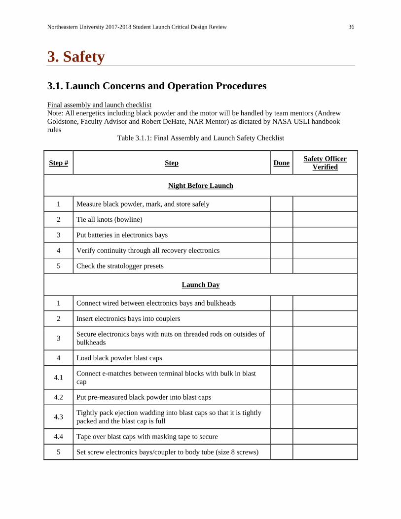
3.1. Launch Concerns and Operation Procedures Final assembly and launch checklist
Note: All energetics including black powder and the motor will be handled by team mentors (Andrew
Goldstone, Faculty Advisor and Robert DeHate, NAR Mentor) as dictated by NASA USLI handbook
rules
Table 3.1.1: Final Assembly and Launch Safety Checklist
Step # Step Done Safety Officer
Verified
Night Before Launch
1 Measure black powder, mark, and store safely
2 Tie all knots (bowline)
3 Put batteries in electronics bays
4 Verify continuity through all recovery electronics
5 Check the stratologger presets
Launch Day
1 Connect wired between electronics bays and bulkheads
2 Insert electronics bays into couplers
3 Secure electronics bays with nuts on threaded rods on outsides of
bulkheads
4 Load black powder blast caps
4.1 Connect e-matches between terminal blocks with bulk in blast
cap
4.2 Put pre-measured black powder into blast caps
4.3 Tightly pack ejection wadding into blast caps so that it is tightly
packed and the blast cap is full
4.4 Tape over blast caps with masking tape to secure
5 Set screw electronics bays/coupler to body tube (size 8 screws)
Northeastern University 2017-2018 Student Launch Critical Design Review 37
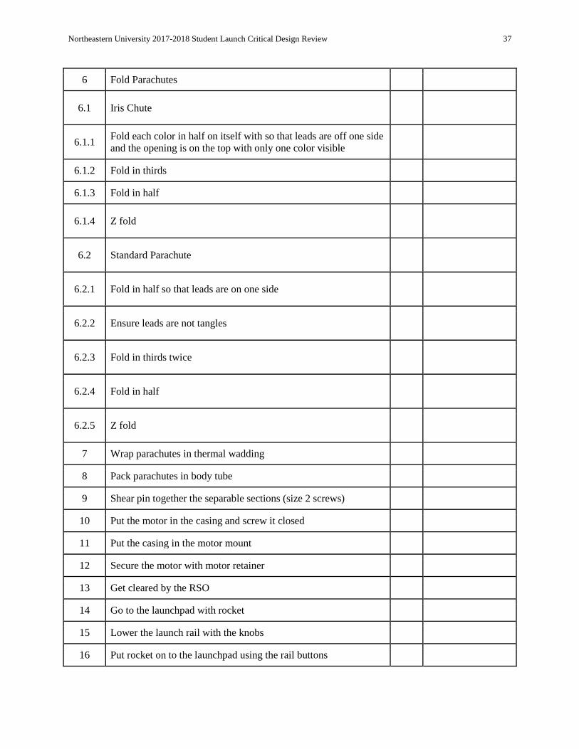
6 Fold Parachutes
6.1 Iris Chute
6.1.1 Fold each color in half on itself with so that leads are off one side
and the opening is on the top with only one color visible
6.1.2 Fold in thirds
6.1.3 Fold in half
6.1.4 Z fold
6.2 Standard Parachute
6.2.1 Fold in half so that leads are on one side
6.2.2 Ensure leads are not tangles
6.2.3 Fold in thirds twice
6.2.4 Fold in half
6.2.5 Z fold
7 Wrap parachutes in thermal wadding
8 Pack parachutes in body tube
9 Shear pin together the separable sections (size 2 screws)
10 Put the motor in the casing and screw it closed
11 Put the casing in the motor mount
12 Secure the motor with motor retainer
13 Get cleared by the RSO
14 Go to the launchpad with rocket
15 Lower the launch rail with the knobs
16 Put rocket on to the launchpad using the rail buttons
Northeastern University 2017-2018 Student Launch Critical Design Review 38
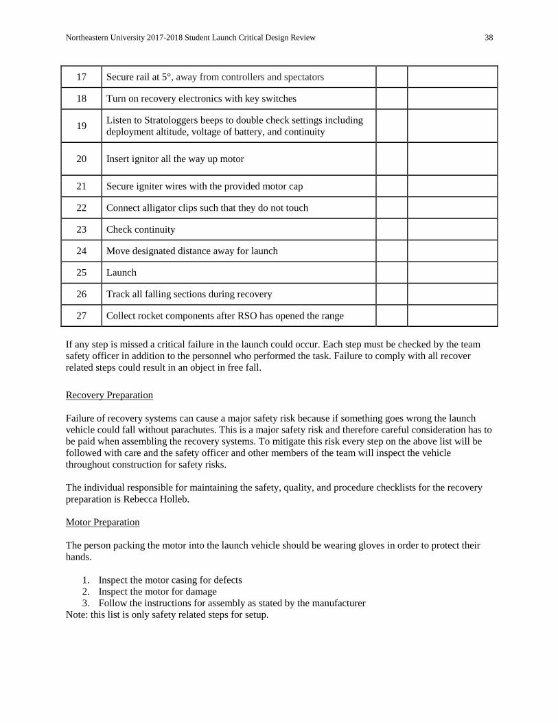
17 Secure rail at 5°, away from controllers and spectators
18 Turn on recovery electronics with key switches
19 Listen to Stratologgers beeps to double check settings including
deployment altitude, voltage of battery, and continuity
20 Insert ignitor all the way up motor
21 Secure igniter wires with the provided motor cap
22 Connect alligator clips such that they do not touch
23 Check continuity
24 Move designated distance away for launch
25 Launch
26 Track all falling sections during recovery
27 Collect rocket components after RSO has opened the range
If any step is missed a critical failure in the launch could occur. Each step must be checked by the team
safety officer in addition to the personnel who performed the task. Failure to comply with all recover
related steps could result in an object in free fall.
Recovery Preparation
Failure of recovery systems can cause a major safety risk because if something goes wrong the launch
vehicle could fall without parachutes. This is a major safety risk and therefore careful consideration has to
be paid when assembling the recovery systems. To mitigate this risk every step on the above list will be
followed with care and the safety officer and other members of the team will inspect the vehicle
throughout construction for safety risks.
The individual responsible for maintaining the safety, quality, and procedure checklists for the recovery
preparation is Rebecca Holleb.
Motor Preparation
The person packing the motor into the launch vehicle should be wearing gloves in order to protect their
hands.
1. Inspect the motor casing for defects
2. Inspect the motor for damage
3. Follow the instructions for assembly as stated by the manufacturer
Note: this list is only safety related steps for setup.

Northeastern University 2017-2018 Student Launch Critical Design Review 39
A faulty motor could cause a safety issue because it could partially burn and fall too soon without
deploying parachutes, it could explode on the launch pad, or it could explode in the air over bystanders.
This can be mitigated by inspecting the motor and the casing for defects before launching.
The individual responsible for maintaining the safety, quality, and procedure checklists for the motor
preparation is Rebecca Holleb.
Setup on Launcher
The risks to the individuals setting the launch vehicle up on the launch pad are centered on the parachute
charges. The armed e-bays could set off the black powder charges, however the chances are slim since the
e-matches will not go off until the altimeters register a specified altitude.
The individual responsible for maintaining the safety, quality, and procedure checklists for the setup on
the launcher is Rebecca Holleb.
Igniter Installation
The biggest risk to individuals undertaking the igniter installation is the accidental ignition of the motor.
We will be instructed when to set up our rocket on the pad by the RSO and it is his or her responsibility to
make sure that while we are installing the igniter that no signal to launch be received by the launch pad
while we are setting up. The risk of such a thing happening is extremely low and as we have never heard
of or witnessed such an event; we consider the risk acceptable. There are no environmental risks related to
igniter installation.
The individual responsible for maintaining the safety, quality, and procedure checklists for the igniter
installation is Rebecca Holleb.
Troubleshooting
Below is a list of systems that could require troubleshooting. Note this is an abbreviated version focused
on safety.
1. Xbee: this system is important for vehicle recovery and data collection, yet is not crucial for
safety
2. Sensor Data: again important for data collection yet not crucial to safety
3. Electronics Bay: failure to troubleshoot if armed incorrectly could result in failure of parachutes
to deploy
If there is an electronics failure it could pose a risk to bystanders if the parachutes do not deploy. This will
be mitigated by checking continuity in the wiring before assembly and listening for the altimeter beeps
when the keys are turned closing the circuit. If there is a problem with the electronics the day of the
launch the vehicle will not be launched until the problem is solved.
The individual responsible for maintaining the safety, quality, and procedure checklists for
troubleshooting is Rebecca Holleb.
Post Flight Inspection

Northeastern University 2017-2018 Student Launch Critical Design Review 40
1. Make sure there is no un-detonated black powder. Failure to complete this step successfully
could result in serious injury due to potential unplanned detonation.
2. Check for any shrapnel or hazardous parts of rocket. Failure to complete this step could result in
injury.
Possible safety issues in retrieving the launch vehicle include possible broken material that could result in
injuries such as cuts as well as undetonated black powder charges that could pose serious safety
risks. The mitigation for these safety risks are that the vehicle will be inspected for both hazards before
being moved. If hazards are found they will be treated accordingly.
The individual responsible for maintaining the safety, quality, and procedure checklists for post-flight
inspection is Rebecca Holleb.
3.2. Safety and Environment (Vehicle and Payload)
Personnel Hazard Analysis
Table 3.2.1 : Personnel Hazard Analysis
Section Hazard Effects Causes Sever
ity
Probabi
lity
Mitigatio
n
Verificati
on
Launch
Hazards
Prematu
re
Motor
Ignition
Severe
burns/bodil
y harm,
general fire
hazard
Improper
storage and
handling of
motor.
Motor placed
near heat
source.
4 1 Follow
MSDS
storage
requireme
nts. Keep
away
from
ignition
sources
Use a
written
procedure
in
accordanc
e with
MSDS
requireme
nts to
ensure
safe
storage.
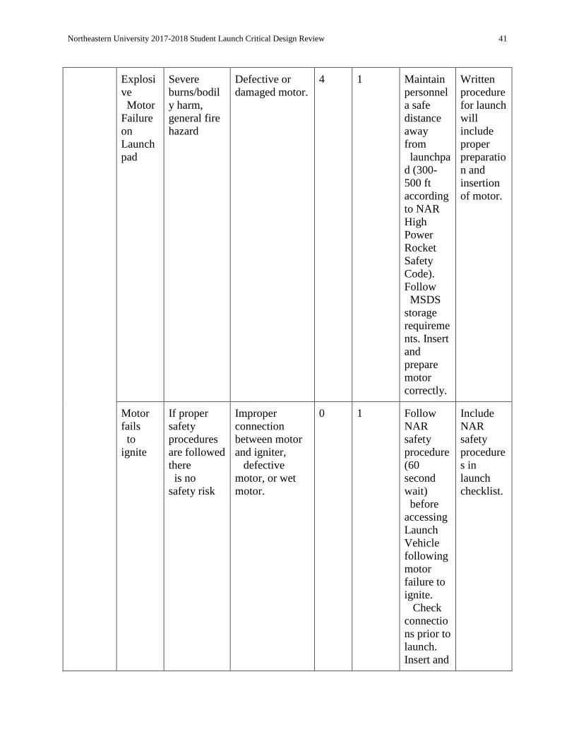
Northeastern University 2017-2018 Student Launch Critical Design Review 41
Explosi
ve
Motor
Failure
on
Launch
pad
Severe
burns/bodil
y harm,
general fire
hazard
Defective or
damaged motor.
4 1 Maintain
personnel
a safe
distance
away
from
launchpa
d (300-
500 ft
according
to NAR
High
Power
Rocket
Safety
Code).
Follow
MSDS
storage
requireme
nts. Insert
and
prepare
motor
correctly.
Written
procedure
for launch
will
include
proper
preparatio
n and
insertion
of motor.
Motor
fails
to
ignite
If proper
safety
procedures
are followed
there
is no
safety risk
Improper
connection
between motor
and igniter,
defective
motor, or wet
motor.
0 1 Follow
NAR
safety
procedure
(60
second
wait)
before
accessing
Launch
Vehicle
following
motor
failure to
ignite.
Check
connectio
ns prior to
launch.
Insert and
Include
NAR
safety
procedure
s in
launch
checklist.

Northeastern University 2017-2018 Student Launch Critical Design Review 42
prepare
motor
properly
before
launch
sequence
is
initiated.
Motor
will be
inspected
before
launch.
Unstabl
e
Flight
Path
The Vehicle
goes on a
flight path
that was
unanticipate
d
One or more
fins fall off,
unintended
oscillation of
the rocket as a
result of
dislodged
internal
components, or
high winds
during launch
4 1 Maintain
personnel
a safe
distance
away
from
launchpa
d (300-
500 ft
according
to NAR
High
Power
Rocket
Safety
Code).
Verify
internal
compone
nts in
electronic
s bays
and
payload
are
secure.
Do not
launch in
Include
NAR
specificati
on and
compone
nt
verificatio
n in the
launch
checklist.

Northeastern University 2017-2018 Student Launch Critical Design Review 43
high wind
condition
s.
Total
Recov
ery
Systems
Failure
No
parachutes
are
deployed,
the Vehicle
is in freefall
The charges do
not detonate or
the sections do
not separate to
release the
parachutes.
4 1 Confirm
that
quantity
of black
powder in
ejection
charges is
sufficient
to
separate
launch
vehicle
sections,
check
recovery
systems
in
electronic
s bay for
proper
connectio
ns, and
verify
altimeter
performa
nce.
Maintain
personnel
a safe
distance
away
Include
extensive
prelaunch
review of
recovery
systems.

Northeastern University 2017-2018 Student Launch Critical Design Review 44
from
launchpad
(300-
500 ft
according
to NAR
High
Power
Rocket
Safety
Code).
Partial
Recov
ery
Systems
Failure
Either the
drogue
parachutes
or the main
parachute
is not
deployed,
the Vehicle
descends
faster than
anticipated
The charges do
not separate
some of the
sections, the
sections do not
release the
parachutes, or
the parachutes
get
tangled on
release. Drogue
parachute or
main parachute
fails to deploy.
3 2 Confirm
that
quantity
of black
powder in
ejection
charges is
sufficient
to
separate
launch
vehicle
sections,
check
recovery
systems
in
electronic
s bay for
proper
connectio
ns, and
verify
altimeter
performa
Include
extensive
prelaunch
review of
recovery
systems.
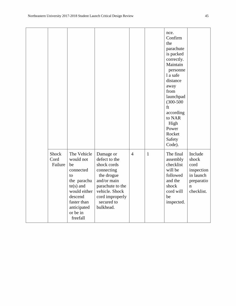
Northeastern University 2017-2018 Student Launch Critical Design Review 45
nce.
Confirm
the
parachute
is packed
correctly.
Maintain
personne
l a safe
distance
away
from
launchpad
(300-500
ft
according
to NAR
High
Power
Rocket
Safety
Code).
Shock
Cord
Failure
The Vehicle
would not
be
connected
to
the parachu
te(s) and
would either
descend
faster than
anticipated
or be in
freefall
Damage or
defect to the
shock cords
connecting
the drogue
and/or main
parachute to the
vehicle. Shock
cord improperly
secured to
bulkhead.
4 1 The final
assembly
checklist
will be
followed
and the
shock
cord will
be
inspected.
Include
shock
cord
inspection
in launch
preparatio
n
checklist.

Northeastern University 2017-2018 Student Launch Critical Design Review 46
Construct
ion
Hazards
Power
Tool
Injury
Injury
incurred
while using
a power tool
Improper
training or tool
maintenance.
Human
error
4 2 Properly
train team
members
on power
tool
handling
, wear
proper
Personal
Protective
Equipmen
t
according
to each
power
tool’s
operator’s
manuals.
Distribute
guidelines
on proper
tool
handling
and PPE.
Tool
Injury
Injury
incurred
while using
a power tool
Improper
training or tool
maintenance.
Human
error
4 2 Properly
train team
members
on tool
handling,
wear
proper
PPE, and
ensure
First Aid
equipmen
t is
available.
Distribute
guidelines
on proper
tool
handling
and PPE.

Northeastern University 2017-2018 Student Launch Critical Design Review 47
Chemic
al
Hazar
ds
Injury
incurred
while using
chemicals
Improper
training or
equipment
maintenance H
uman error
4 2 Train
team
members
on
chemical
handling,
and
follow
proper
storage
requireme
nts listed
on
MSDS,
provide
proper
PPE
accordin
g to the
material’s
instructio
ns, utilize
chemicals
only in
areas
designat
ed for
their use.
Distribute
chemical
handling
and
storage
guidelines
in
accordanc
e are
MSDS
requireme
nts.
Fire
Hazard
Injury
incurred due
to a fire
Improper
training. Huma
n error
4 2 Keep fire
hazardous
materials
stored
properly
accordin
g to
MSDS.
Use
written
procedure
in
accordanc
e with
MSDS.
Northeastern University 2017-2018 Student Launch Critical Design Review 48
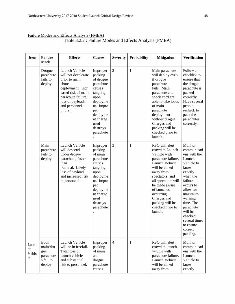
Failure Modes and Effects Analysis (FMEA)
Table 3.2.2 : Failure Modes and Effects Analysis (FMEA)
Item Failure
Mode Effects Causes Severity Probability Mitigation Verification
Laun
ch
Vehic
le
Drogue
parachute
fails to
deploy
Launch Vehicle
will not decelerate
prior to main
chute
deployment. Incr
eased risk of main
parachute failure,
loss of payload,
and personnel
injury.
Improper
packing
of drogue
parachute
causes
tangling
upon
deployme
nt. Impro
per
deployme
nt charge
used
destroys
parachute
.
2 1 Main parachute
will deploy even
if drogue
parachute
fails. Main
parachute and
shock cord are
able to take loads
of main
parachute
deployment
without drogue.
Charges and
packing will be
checked prior to
launch.
Follow a
checklist to
ensure that
the drogue
parachute is
packed
correctly.
Have several
people
recheck to
pack the
parachutes
correctly.
Main
parachute
fails to
deploy
Launch Vehicle
will descend
under drogue
parachute, faster
than
nominal. Likely
loss of payload
and increased risk
to personnel.
Improper
packing
of main
parachute
causes
tangling
upon
deployme
nt. Impro
per
deployme
nt charge
used
destroys
parachute
.
3 1 RSO will alert
crowd to Launch
Vehicle with
parachute failure,
Launch Vehicle
will be aimed
away from
spectators, and
all spectators will
be made aware
of launches
occurring.
Charges and
packing will be
checked prior to
launch.
Monitor
communicati
ons with the
Launch
Vehicle to
know
exactly
when the
failure
occurs to
allow for
maximum
warning
time. The
parachute
will be
checked
several times
to ensure
correct
packing.
Both
main/dro
gue
parachute
s fail to
deploy
Launch Vehicle
will be in freefall.
Total loss of
launch vehicle
and substantial
risk to personnel.
Improper
packing
of main
and
drogue
parachute
causes
4 1 RSO will alert
crowd to launch
vehicle with
parachute failure,
Launch Vehicle
will be aimed
away from
Monitor
communicati
ons with the
Launch
Vehicle to
know
exactly

Northeastern University 2017-2018 Student Launch Critical Design Review 49
tangling
upon
deployme
nt. Impro
per
deployme
nt charge
used
destroys
parachute
s.
spectators, and
all spectators will
be made aware
of launches
occurring.
Charges and
packing will be
checked prior to
launch.
when the
failure
occurs to
allow for
maximum
warning
time. The
parachute
will be
checked
several times
to ensure
correct
packing.
Shock
cord
failure
(drogue)
Parachute
detaches from
Launch
Vehicle. Increase
d loads on main
parachute
deployment. Incr
eased risk of main
parachute failure,
loss of payload,
and personnel
injury.
Weakeni
ng or
damage
to shock
cord from
accidenta
l cutting
or epoxy.
2 1 Shock cord will
be kept away
from
unintentional
cutting and
epoxy. Main
parachute and
shock cord are
able to take loads
of main
parachute
deployment
without drogue.
Shock
cord
failure
(main)
Parachute
detaches from
Launch
Vehicle. Launch
Vehicle will
descend under
drogue parachute
at increased
speed. Likely
loss of payload
and increased risk
to personnel.
Weakeni
ng or
damage
to shock
cord from
accidenta
l cutting
or epoxy.
3 1 Attachment point
is
reinforced. Shoc
k cord is ½”
Kevlar. Finite
element analysis
of shock cord
and bulkhead
performed to
ensure they can
withstand
parachute
deployment. Sho
ck cord will be
kept away from
unintentional
cutting and
epoxy.
Shock
cord
failure
(both)
Both parachutes
detach from
Launch Vehicle.
Launch Vehicle
will be in freefall.
Total loss of
launch vehicle
Weakeni
ng or
damage
to shock
cord from
accidenta
l cutting
4 1 Shock cord will
be kept away
from
unintentional
cutting and
epoxy. Shock
cord will be
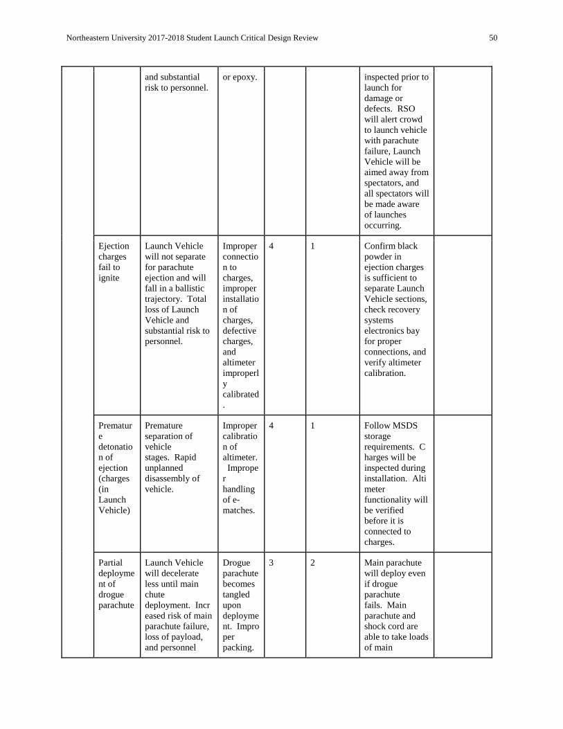
Northeastern University 2017-2018 Student Launch Critical Design Review 50
and substantial
risk to personnel. or epoxy. inspected prior to
launch for
damage or
defects. RSO
will alert crowd
to launch vehicle
with parachute
failure, Launch
Vehicle will be
aimed away from
spectators, and
all spectators will
be made aware
of launches
occurring.
Ejection
charges
fail to
ignite
Launch Vehicle
will not separate
for parachute
ejection and will
fall in a ballistic
trajectory. Total
loss of Launch
Vehicle and
substantial risk to
personnel.
Improper
connectio
n to
charges,
improper
installatio
n of
charges,
defective
charges,
and
altimeter
improperl
y
calibrated
.
4 1 Confirm black
powder in
ejection charges
is sufficient to
separate Launch
Vehicle sections,
check recovery
systems
electronics bay
for proper
connections, and
verify altimeter
calibration.
Prematur
e
detonatio
n of
ejection
(charges
(in
Launch
Vehicle)
Premature
separation of
vehicle
stages. Rapid
unplanned
disassembly of
vehicle.
Improper
calibratio
n of
altimeter.
Imprope
r
handling
of e-
matches.
4 1 Follow MSDS
storage
requirements. C
harges will be
inspected during
installation. Alti
meter
functionality will
be verified
before it is
connected to
charges.
Partial
deployme
nt of
drogue
parachute
Launch Vehicle
will decelerate
less until main
chute
deployment. Incr
eased risk of main
parachute failure,
loss of payload,
and personnel
Drogue
parachute
becomes
tangled
upon
deployme
nt. Impro
per
packing.
3 2 Main parachute
will deploy even
if drogue
parachute
fails. Main
parachute and
shock cord are
able to take loads
of main

Northeastern University 2017-2018 Student Launch Critical Design Review 51
injury. parachute
deployment
without drogue.
Packing will be
checked prior to
launch.
Partial
deployme
nt of
main
parachute
Launch Vehicle
will descend
under drogue
parachute and
partially deployed
main, faster than
nominal. Likely
loss of payload
and increased risk
to personnel.
Main
parachute
becomes
tangled
upon
deployme
nt. Impro
per
packing.
3 2 Launch Vehicle
will be aimed
away from
spectators, and
all spectators will
be made aware
of launches
occurring.
Packing will be
checked prior to
launch.
Partial
deployme
nt of both
drogue/m
ain
parachute
s
Vehicle will fall
at increased speed
under partially
deployed
parachutes.
Potential loss of
launch vehicle
and substantial
risk to personnel.
Main and
drogue
chutes
could
become
tangled
with one
another.
Improper
packing.
3 1 RSO will alert
crowd to launch
vehicle with
parachute failure,
Launch Vehicle
will be aimed
away from
spectators, and
all spectators will
be made aware
of launches
occurring. Packi
ng will be
checked prior to
launch.
Rapid
unplanne
d
disassem
bly of
Vehicle
(RUD)
Vehicle will break
apart in an
unplanned
manner. Loss of
vehicle structural
integrity and
increased risk to
personnel due to
vehicle
components in
freefall.
Structural
defect in
Launch
Vehicle
body.
4 1 In the event of a
RUD with the
vehicle breaking
apart along its
coupler tubes,
parachutes may
passively deploy
for each
section. Verify
that the Vehicle
is structurally
stable.
Explosive
motor
failure on
launch pad
Significant risk of
severe personnel harm
and fire
hazard. Significant risk
of loss of vehicle and
payload.
Defective or
damaged motor. 4 1 Follow MSDS storage
requirements. Insert and
prepare motor properly
before launch sequence is
initiated. Motor will be
inspected before launch.
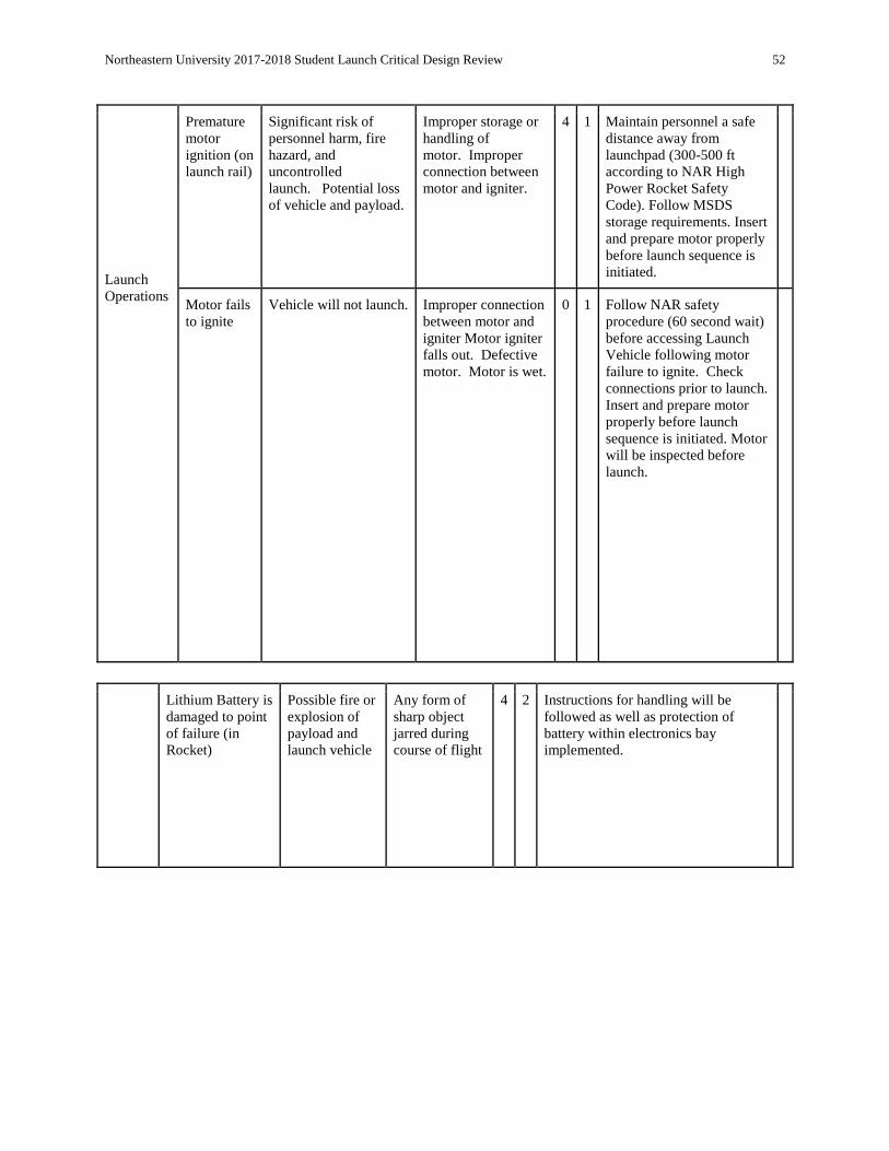
Northeastern University 2017-2018 Student Launch Critical Design Review 52
Launch
Operations
Premature
motor
ignition (on
launch rail)
Significant risk of
personnel harm, fire
hazard, and
uncontrolled
launch. Potential loss
of vehicle and payload.
Improper storage or
handling of
motor. Improper
connection between
motor and igniter.
4 1 Maintain personnel a safe
distance away from
launchpad (300-500 ft
according to NAR High
Power Rocket Safety
Code). Follow MSDS
storage requirements. Insert
and prepare motor properly
before launch sequence is
initiated.
Motor fails
to ignite Vehicle will not launch. Improper connection
between motor and
igniter Motor igniter
falls out. Defective
motor. Motor is wet.
0 1 Follow NAR safety
procedure (60 second wait)
before accessing Launch
Vehicle following motor
failure to ignite. Check
connections prior to launch.
Insert and prepare motor
properly before launch
sequence is initiated. Motor
will be inspected before
launch.
Lithium Battery is
damaged to point
of failure (in
Rocket)
Possible fire or
explosion of
payload and
launch vehicle
Any form of
sharp object
jarred during
course of flight
4 2 Instructions for handling will be
followed as well as protection of
battery within electronics bay
implemented.

Northeastern University 2017-2018 Student Launch Critical Design Review 53
Payload
Lithium Battery is
damaged to point
of failure (on
ground)
Possible fire or
explosion of
payload
Any form of
sharp object
dislocated upon
landing
2 2 Instructions for handling will be
followed as well as protection of
battery within electronics bay
implemented.
Punctured
pressurized gas
containment
Leak and
possible
explosion
Any jagged
edges 3 2 All guidelines set forth by NASA
USLI will be followed for pressurized
air in vehicle, all containment systems
for the pressurized air will have high
safety factors and possible sources of
punctured minimized.
Launch
Operations
Explosive
motor
failure on
launch pad
Significant risk of
severe personnel harm
and fire
hazard. Significant risk
of loss of vehicle and
payload.
Defective or
damaged motor. 4 1 Follow MSDS storage
requirements. Insert and
prepare motor properly
before launch sequence is
initiated. Motor will be
inspected before launch.
Premature
motor
ignition (on
launch rail)
Significant risk of
personnel harm, fire
hazard, and
uncontrolled
launch. Potential loss
of vehicle and payload.
Improper storage or
handling of
motor. Improper
connection between
motor and igniter.
4 1 Maintain personnel a safe
distance away from
launchpad (300-500 ft
according to NAR High
Power Rocket Safety
Code). Follow MSDS
storage requirements. Insert
and prepare motor properly
before launch sequence is
initiated.
Motor fails
to ignite Vehicle will not launch. Improper connection
between motor and
igniter Motor igniter
falls out. Defective
motor. Motor is wet.
0 1 Follow NAR safety
procedure (60 second wait)
before accessing Launch
Vehicle following motor
failure to ignite. Check
connections prior to launch.
Insert and prepare motor
properly before launch
sequence is initiated. Motor
will be inspected before

Northeastern University 2017-2018 Student Launch Critical Design Review 54
launch.
Ground
Support
Equipment
Launch
Vehicle falls
off launch
rail
Launch Vehicle falls off
launch rail. If motor is lit,
Launch Vehicle will fire
off in uncontrolled
direction. Substantial risk
to personnel and
bystanders.
Launch rail
improperly secured
by RSO
4 1 RSO properly sets up
launch rail.
Premature
motor
ignition
(prior to
installation)
Significant risk of
personnel harm and
general fire hazard.
Heat source placed
near
motors. Improper
handling of motors.
4 1 Motors will be
provided the day of
launch. Will only be
handled by qualified
personnel. Follow
MSDS storage
requirements.
Premature
detonation of
ejection
charges (prior
to
installation)
Significant risk of
personnel harm and
general fire hazard.
Heat source placed
near
charges. Improper
handling of charges.
4 1 Charges will be
provided the day of
launch. Will only be
handled by qualified
personnel. Follow
MSDS storage
requirements.
Likelihood Definitions
Table 3.2.3 : Likelihood Definitions
Likelihood Definition Ranking
Remote Significant negligence and major defects required for hazard to occur. 1
Unlikely Significant negligence or defects required for hazard to occur. 2
Possible May occur despite proper safety measures and equipment checks taking place. 3
Likely Expected to occur despite proper safety measures and equipment checks taking
place. 4
Severity Definitions
Table 3.2.4 : Severity Definitions
Severity Definition Rank
Catastrophic Environment causes complete loss of system, or system causes significant permanent 4

Northeastern University 2017-2018 Student Launch Critical Design Review 55
damage to environment.
Major Major depletion of system functionality, substantial effect on environment. 3
Moderate Partial effect on system functionality, some effect on environment. 2
Minor Small effect on system functionality, mild environmental concern. 1
No Effect System stays intact, environmental conditions never altered. 0
The following table represents a list of environmental concerns associated with the launch vehicle.
Environmental Concerns
Table 3.2.5 : Environmental Concerns
Environmental
Concern Effects Causes Severi
ty Probab I l ity
Mitigation Verification
Motor
Chemicals Possible
contamination of
environment
surrounding Launch
Vehicle during
launch preparations
or launch sequence.
Improper handling
of
motor. Propellant
falls out of
dropped motor.
1 1 Transport and
load motor into
launch vehicle
properly,
according to
MSDS and
motor operator’s
manuals.
Have a
written
launch
procedure in
accordance
with MSDS
and motor
operator’s
manuals.
Impact of Motor
Ignition on
Launch Area
Possible fire or heat
damage to
immediate area
around launch
area. Potential fire
hazard.
No shield between
motor exhaust and
ground.
1 1 Plate mounted
on launch rail
between motor
to prevent motor
exhaust from
burning launch
area.
Verify launch
setup with
site
personnel.
Debris from
rapid unplanned
disassembly of
Launch Vehicle
Depending on the
scale of the vehicle
failure, debris
consistency and size
may vary. Debris
may consist of
carbon fiber and
“blue tube”
fragments.
Catastrophic
failure of
separation charges
or recovery
system of vehicle.
2 1 Launch Vehicle
systems will be
fully inspected
before launch to
mitigate
probability of
vehicle
failure. In the
event of a
failure, area will
be policed for
debris.
Checklist for
Launch
Vehicle
inspection.
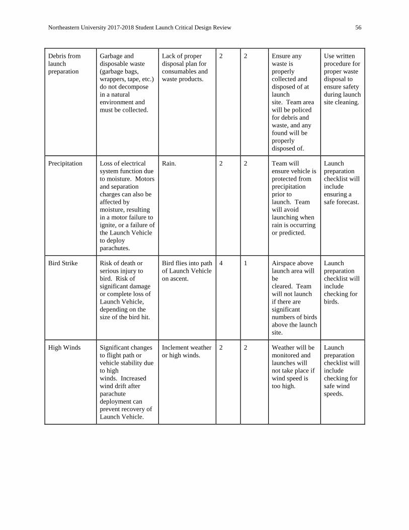
Northeastern University 2017-2018 Student Launch Critical Design Review 56
Debris from
launch
preparation
Garbage and
disposable waste
(garbage bags,
wrappers, tape, etc.)
do not decompose
in a natural
environment and
must be collected.
Lack of proper
disposal plan for
consumables and
waste products.
2 2 Ensure any
waste is
properly
collected and
disposed of at
launch
site. Team area
will be policed
for debris and
waste, and any
found will be
properly
disposed of.
Use written
procedure for
proper waste
disposal to
ensure safety
during launch
site cleaning.
Precipitation Loss of electrical
system function due
to moisture. Motors
and separation
charges can also be
affected by
moisture, resulting
in a motor failure to
ignite, or a failure of
the Launch Vehicle
to deploy
parachutes.
Rain. 2 2 Team will
ensure vehicle is
protected from
precipitation
prior to
launch. Team
will avoid
launching when
rain is occurring
or predicted.
Launch
preparation
checklist will
include
ensuring a
safe forecast.
Bird Strike Risk of death or
serious injury to
bird. Risk of
significant damage
or complete loss of
Launch Vehicle,
depending on the
size of the bird hit.
Bird flies into path
of Launch Vehicle
on ascent.
4 1 Airspace above
launch area will
be
cleared. Team
will not launch
if there are
significant
numbers of birds
above the launch
site.
Launch
preparation
checklist will
include
checking for
birds.
High Winds Significant changes
to flight path or
vehicle stability due
to high
winds. Increased
wind drift after
parachute
deployment can
prevent recovery of
Launch Vehicle.
Inclement weather
or high winds. 2 2 Weather will be
monitored and
launches will
not take place if
wind speed is
too high.
Launch
preparation
checklist will
include
checking for
safe wind
speeds.

Northeastern University 2017-2018 Student Launch Critical Design Review 57
4. Payload Criteria
4.1. Design of Payload Equipment
4.1.1. Wheels The decision making process was completed through the use of comparison charts to weigh the pros and
cons of various options as seen in Table 4.1.1.1. The first design decision was to consider the number of
wheels on the rover. One option was for the rover to have four wheels. This idea has a number of pros
such as a robust, simple design, and the ability to maneuver over rough terrain. Some of the cons are that
it severely limits chassis size, limits wheel size, and the rover would be unable to self-right itself, which
would make the ejection system more complicated and dependent on payload orientation. A four-wheeled
rover would cause many severe problems, led the team to rule it out as one of the options for our final
design.
Another concept for wheel design on the rover is a tracked design, similar to tank treads. The pro that
come with this design is that it is best for rough terrain and turning. This rover would also have a robust
interface with the ejection system; another positive. Many of the limitations from the four-wheel design
carry are also applicable. It is a complex design and there is the possibility of the rover separating from
the tracks. The tracks would also limit the space and size of the rover because they take up space inside
the Launch Vehicle. The idea for a tracked design was also ruled out because of the complexity and the
challenges that face this design such as timing and idler wheels.
The third, and final, design is for a two-wheeled rover with one additional support appendage for
stabilization. This rover would be self-righting and allow a maximum chassis size compared to the
Launch Vehicle diameter. This design will allow for the rover to utilize counter-torque for self-righting
capability. The two-wheeled rover would allow for a larger wheel size and therefore utilize space in the
Launch Vehicle. Although this design has many positives, there are also some drawbacks. One of the
drawbacks is that the ejection process will be the amount of force between the wheel surface and launch
vehicle interface. This has the potential to cause problems on the wheel axle such as wheel deformation.
The material design will take into account the applied forces. Rough terrain is also more of a challenge
for the two-wheeled rover because it has less stability and ability to navigate the ground surface.
Although the design is less stable, a two-wheeled rover was determined to be the best design to complete
the challenge criteria.
Table 4.1.1.1: Decision Matrix for Wheel Design where each criterion was ranked and the design
alternative with the highest total value was considered the best design. Green indicates the chosen primary
design.
Criteria 4- Wheels 2-Wheels Treads
Size 2 3 1
Maneuverability 3 1 2
Stability 1 3 2
Complexity -2 -1 -3

Northeastern University 2017-2018 Student Launch Critical Design Review 58
Total 4 6 2
4.1.2. Ejection Another challenging design aspect is to determine how to eject the rover from the Launch Vehicle. Three
designs were evaluated in Table 4.1.2.1 one of the designs that was considered was a side hatch in the
Launch Vehicle which would be ejected by an airbag. This concept would bring the least amount of
potential damage to the rover during separation. A hatch also does not require separating the launch
vehicle sections on the ground. However, a hatch in the side of the rocket would severely reduce the
structural integrity of the Launch Vehicle. This hatch idea also depends on the Launch Vehicle landing in
the correct orientation so the hatch can open and the rover can properly exit the Vehicle. To add to the
negative aspect of this design, the rover may have trouble exiting the Launch Vehicle under its own
power. This is because the Launch Vehicle is cylindrical and creates a “U” shape when the hatch is
opened; thus creating a difficulty for the rover to exit. After considering all of these pros and cons, it was
determined that the hatch idea would be too difficult to execute successfully.
The second concept that was considered was a spring system to push the rover out of the Launch Vehicle.
The spring system would function independent of the orientation of the Launch Vehicle after it lands,
which is a pro compared to the hatch concept, which depends upon the orientation. The spring system
also occupies less space than the pneumatic piston design, which is explained below. It is desirable for the
ejection system to be as compact as possible so that more space can be allotted to the rover. A larger rover
will be more capable of completing its requirements. One of the pitfalls of the spring system is that it
cannot be gradually controlled, like the pneumatic piston can, so it has a greater chance of damaging the
rover. Another con is that the Motor Section needs to be ejected far enough away from the Payload
Section so that it does not obstruct the deployment of the rover. The spring system may not be able to
consistently and successfully push the rover out of the Launch Vehicle, and therefore was determined not
to be a viable option as an ejection method.
The final idea that was considered is the pneumatic piston. This is the concept that was ultimately
determined to be the most successful and the best idea to deploy the rover. The system does require space
for the pneumatic components, which is a downside. Also, there is a risk of puncture and the Motor
Section needs to be ejected far enough away from the Payload section as to not obstruct the rover exiting
the Launch Vehicle. With the pneumatic system, the rover can be deployed safely because the regulator,
valve, and speed controller can be controlled to adjust for the correct pressure and flow rate. This system
also does not depend on the orientation that the Launch Vehicle lands in. When considering all of these
factors and concepts, the best design to eject the rover from the Launch Vehicle is to use the pneumatic
piston.
Table 4.1.2.1: Decision Matrix for Rover Deployment, each criterion was ranked and design
alternative with least negative total value was the best design. Green indicates the chosen primary design.
Criteria Side Hatch Spring Forced Pneumatic Piston
Orientation 1 2 3
Structural Integrity of LV -3 -2 -1
Complexity -1 -2 -3
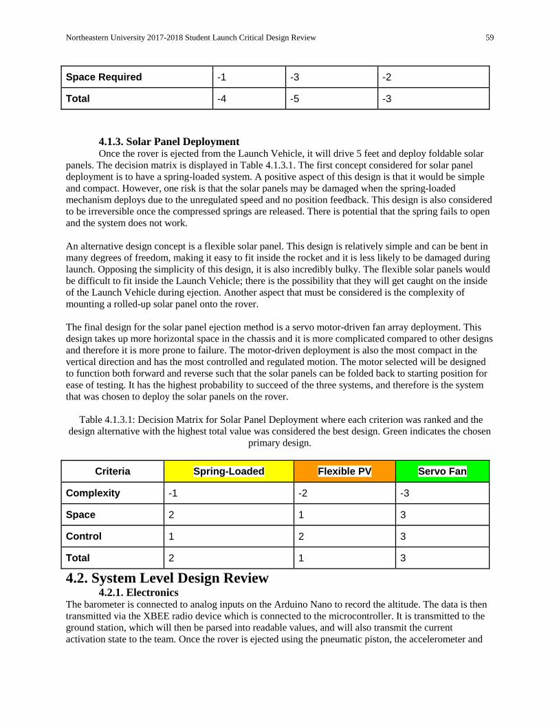
Northeastern University 2017-2018 Student Launch Critical Design Review 59
Space Required -1 -3 -2
Total -4 -5 -3
4.1.3. Solar Panel Deployment Once the rover is ejected from the Launch Vehicle, it will drive 5 feet and deploy foldable solar
panels. The decision matrix is displayed in Table 4.1.3.1. The first concept considered for solar panel
deployment is to have a spring-loaded system. A positive aspect of this design is that it would be simple
and compact. However, one risk is that the solar panels may be damaged when the spring-loaded
mechanism deploys due to the unregulated speed and no position feedback. This design is also considered
to be irreversible once the compressed springs are released. There is potential that the spring fails to open
and the system does not work.
An alternative design concept is a flexible solar panel. This design is relatively simple and can be bent in
many degrees of freedom, making it easy to fit inside the rocket and it is less likely to be damaged during
launch. Opposing the simplicity of this design, it is also incredibly bulky. The flexible solar panels would
be difficult to fit inside the Launch Vehicle; there is the possibility that they will get caught on the inside
of the Launch Vehicle during ejection. Another aspect that must be considered is the complexity of
mounting a rolled-up solar panel onto the rover.
The final design for the solar panel ejection method is a servo motor-driven fan array deployment. This
design takes up more horizontal space in the chassis and it is more complicated compared to other designs
and therefore it is more prone to failure. The motor-driven deployment is also the most compact in the
vertical direction and has the most controlled and regulated motion. The motor selected will be designed
to function both forward and reverse such that the solar panels can be folded back to starting position for
ease of testing. It has the highest probability to succeed of the three systems, and therefore is the system
that was chosen to deploy the solar panels on the rover.
Table 4.1.3.1: Decision Matrix for Solar Panel Deployment where each criterion was ranked and the
design alternative with the highest total value was considered the best design. Green indicates the chosen
primary design.
Criteria Spring-Loaded Flexible PV Servo Fan
Complexity -1 -2 -3
Space 2 1 3
Control 1 2 3
Total 2 1 3
4.2. System Level Design Review 4.2.1. Electronics
The barometer is connected to analog inputs on the Arduino Nano to record the altitude. The data is then
transmitted via the XBEE radio device which is connected to the microcontroller. It is transmitted to the
ground station, which will then be parsed into readable values, and will also transmit the current
activation state to the team. Once the rover is ejected using the pneumatic piston, the accelerometer and

Northeastern University 2017-2018 Student Launch Critical Design Review 60
gyroscope is used to measure and record the position and the chassis orientation of the rover starting from
its initial point.
4.2.2. Solar Panel
A flexible 6V 1W solar panel will be deployed using a servo motor driven fan array to rotate the panels
from 0 to 180 degrees. The panels will be connected to the onboard electronics, and the energy generated
will be used to light up an indicator light. The motor is designed to function both forward and backwards
in order for the solar panels to be folded back into its initial position.
4.2.2. Solar Panel A flexible 6V 1W solar panel will be deployed using a servo motor driven fan array to rotate the panels
from 0 to 180 degrees. The panels will be connected to the onboard electronics, and the energy generated
will be used to light up an indicator light. The motor is designed to function both forward and backwards
in order for the solar panels to be folded back into its initial position.
4.2.3. Wheels
The rover has 2 wheels that have a diameter of 5.9 inches each. The cores of the wheels are 3D printed
and then sprayed with a rubber coating to provide traction on the rough terrain. Two Vex 2 Wire Motors
are used to drive the wheels of the rover.
4.2.3. Payload Ejection System
Prior to launch, a Peregrine CO2 ejection system pressurizes the pneumatic system. A compact regulator
will drop the pressure to approximately 35 psi. A 3 ported, 2 way internally piloted normally closed valve
following the regulator will remain shut until a 12V signal is received from the PES electronics bay (after
a signal from the ground station is received). A speed controller (set prior to launch) will control the flow
of the CO2 once the valve is opened. Bellows, constructed from polyester film, will be expanded, pushing
the forward bulkhead and the rover from the rocket. The bellows will be clamped to the forward and rear
bulkheads. The forward bulkhead has three bushings epoxied to it. These bushings slide along steel rods
which are affixed to the rear bulkhead. All components are connected with nylon tubing (1/4” OD and
11/64” ID) and barbed fittings (¼ NPT).
4.3. Drawings and Specifications for Components and Assembly The Payload Ejection System has two states: retracted and extended. The major dimensions of both states
are shown below in Figure 4.3.1. Note that the polyester film is not shown.

Northeastern University 2017-2018 Student Launch Critical Design Review 61
Figure 4.3.1: Extended and Retracted Payload Ejection System
The PES contains 3 bulkheads: The forward bulkhead, the rear bulkhead, and the pneumatic base
bulkhead. The forward and rear bulkheads have the same profile and are shown below in Figure 4.3.2.
Note that the rear bulkhead has no bushings, but rather epoxy to retain the steel rods.
Figure 4.3.2: Profile of forward and rear bulkheads

Northeastern University 2017-2018 Student Launch Critical Design Review 62
The pneumatic components are mounted to the pneumatic base bulkhead and are shown below in Figure
4.3.3.
Figure 4.3.3: Pneumatic layout
The electronics to control the pneumatic system and to communicate with the ground station and the rover
are shown below in Figure 4.3.4. They are mounted to the pneumatic components bulkhead.
Figure 4.3.4: Electronic layouts
An engineering drawing of the rover body is shown below in Figure 4.3.5.
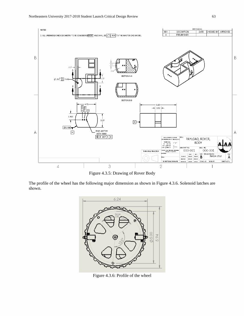
Northeastern University 2017-2018 Student Launch Critical Design Review 63
Figure 4.3.5: Drawing of Rover Body
The profile of the wheel has the following major dimension as shown in Figure 4.3.6. Solenoid latches are
shown.
Figure 4.3.6: Profile of the wheel

Northeastern University 2017-2018 Student Launch Critical Design Review 64
The length of the rover is shown below in Figure 4.3.7.
Figure 4.3.7: Length of the Rover
4.4. Payload Component Interaction Description
4.4.1. Payload Component Interaction Overview
The NU-Frontiers payload consists of two major sections which must interface with one another. The
payload section includes the NU-Frontiers Rover (NUFR) and Payload Ejection System (PES). These
sections must effectively communicate with one another to assure successful payload ejection and on
ground performance.
To begin, we will start with a high level overview of the NUFR payload, what NUFR consists of, and
how these components are composed to create a functioning rover.
4.4.2. NUFR Component Interaction
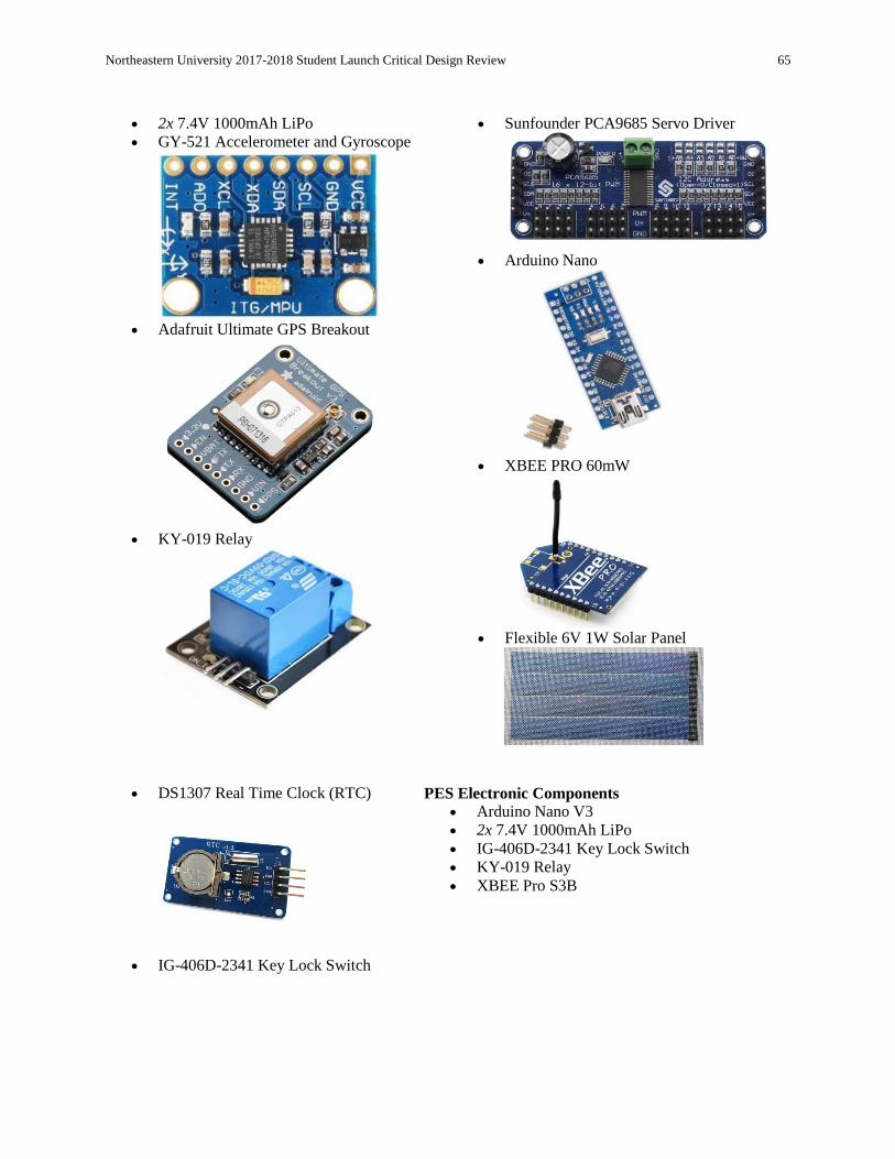
Northeastern University 2017-2018 Student Launch Critical Design Review 65
2x 7.4V 1000mAh LiPo
GY-521 Accelerometer and Gyroscope
Adafruit Ultimate GPS Breakout
KY-019 Relay
Sunfounder PCA9685 Servo Driver
Arduino Nano
XBEE PRO 60mW
Flexible 6V 1W Solar Panel
DS1307 Real Time Clock (RTC)
IG-406D-2341 Key Lock Switch
PES Electronic Components Arduino Nano V3
2x 7.4V 1000mAh LiPo
IG-406D-2341 Key Lock Switch
KY-019 Relay
XBEE Pro S3B

Northeastern University 2017-2018 Student Launch Critical Design Review 66
S3170G Servo (Tail Servo)
BLS-173SV Servo (Solar Servo)
Vex 2 Wire 393 Motor (Drive Motor)
BMP180 Barometer/Altimeter
Relieving air regulator
3 ported, 2 way internally piloted solenoid
valve
The NU-Frontiers Rover is designed with autonomous function in mind. Once the rover exits the launch
vehicle and separates from the PES ejection system, it must complete tasks without outside interference.
Keeping that in mind, the rover must still be able to interface with the PES ejection system, and by proxy,
the ground station.
This system consists of a microcontroller, keylock switch, radio device, relay, gyroscope, GPS, servo
driver, and RTC. During launch the system will remain in a ‘sleep state’, waiting for the signal to activate,
while in this sleep state the GPS position will be relayed to the ejection system back to the ground station.
On signal reception by the ejection system, another signal will be sent to the rover via the ejection system,
activating the system.

Northeastern University 2017-2018 Student Launch Critical Design Review 67
On activation, the RTC will begin counting. During ejection tests a safe time estimate for ejection will be
determined, and the Arduino - RTC system will wait until that time is reached. Once the timer has
reached this predetermined count, the rover will begin operation. First the servo driver will flip out a ski to provide counter moment for rover movement, following this
event the relay onboard the rover will activate, connecting the wheel motors to ~7.4V of power (two 7.4V
LiPos connected in parallel). At this point the RTC will begin another count, this time to a predetermined
estimate (based on tests for rover distance), after this time has passed, the relay will switch to its ‘off’
position, cutting off wheel motor power. Next the PWM driver will actuate the solar servo, deploying
solar panels and completing the rover task.
4.4.3. PES Component Interaction This system consists of an Arduino Nano microcontroller, XBee Pro 60mW, KY-019 relay, two 7.4 V
1000mAh LiPo Batteries, BMP180 barometer, 5V and 12V voltage regulators, and a keylock switch.
These components are all soldered to a protoboard. The pneumatic components consist of the CO2
cartridge (standard 12g size), a Peregrine CO2 Ejection System, a compact pressure regulator with an
internal relief valve, a 3 ported, 2 way internally piloted solenoid valve, a speed controller, and a
polyester bellow. Structurally, the system consists of 3 bulkheads and 3 steel rods. The bulkheads are the
pneumatic base bulkhead will be set screwed in place. The rear bulkhead (between the front bulkhead and
the pneumatic base bulkhead) will be epoxied in place. The forward bulkhead will not be fixed to the
body tube; instead it will be free to slide along the steel rods affixed to the rear bulkhead. All bulkheads
will be within the body and will have a diameter slightly smaller than the body tube ID (~5.95 inches). Before launch, the keylock switch (wired in series with the battery and microcontroller) will be turned,
powering the system. At this point the barometer, connected to analog inputs on the microcontroller will
begin recording altitude. This data will be transmitted via XBEE radio device connected to the
microcontroller. In turn, the ground station will receive this data and parse it as human readable values.
Additionally the radio will transmit the current ‘activation state’ (see definition below) for the rover. The activation state will be set as 0 from rocket launch to landing, once the activation signal is sent from
the ground station and received by the PES; the activation state will be set as 1. On system ‘activation’, a signal will be sent from the high powered XBEE in PES to the low powered
XBEE on the rover. On signal reception, the ejection system will activate. On activation the relay will be
powered, which will in turn send a 12V signal to the solenoid valve, starting the ejection process. Prior to vehicle assembly, a CO2 ejection system will pressurize the pneumatic system. After receiving a
signal from the ground station and changing the state to “activation state” to 1, the valve will open and fill
the bellows. The pressure within the bellows will push the rover out of the launch vehicle. Once rover ejection has completed the PES will work as a proxy, relaying data from the rover to the
ground station.
4.5. Payload Integration Plan The full scale rocket contains a payload section that is placed into the body tube of the launch vehicle.
This payload section contains the NU Frontiers rover (NUFR) and the Payload Ejection System (PES).
Two bulkheads of the PES are rigidly connected to the body tube of the launch vehicle by two bulkheads.
The pneumatic base bulkhead is set screwed in place and the rear bulkhead is epoxied in place. The
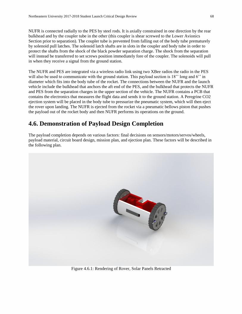
Northeastern University 2017-2018 Student Launch Critical Design Review 68
NUFR is connected radially to the PES by steel rods. It is axially constrained in one direction by the rear
bulkhead and by the coupler tube in the other (this coupler is shear screwed to the Lower Avionics
Section prior to separation). The coupler tube is prevented from falling out of the body tube prematurely
by solenoid pull latches. The solenoid latch shafts are in slots in the coupler and body tube in order to
protect the shafts from the shock of the black powder separation charge. The shock from the separation
will instead be transferred to set screws position immediately fore of the coupler. The solenoids will pull
in when they receive a signal from the ground station. The NUFR and PES are integrated via a wireless radio link using two XBee radios the radio in the PES
will also be used to communicate with the ground station. This payload section is 18’’ long and 6’’ in
diameter which fits into the body tube of the rocket. The connections between the NUFR and the launch
vehicle include the bulkhead that anchors the aft end of the PES, and the bulkhead that protects the NUFR
and PES from the separation charges in the upper section of the vehicle. The NUFR contains a PCB that
contains the electronics that measures the flight data and sends it to the ground station. A Peregrine CO2
ejection system will be placed in the body tube to pressurize the pneumatic system, which will then eject
the rover upon landing. The NUFR is ejected from the rocket via a pneumatic bellows piston that pushes
the payload out of the rocket body and then NUFR performs its operations on the ground.
4.6. Demonstration of Payload Design Completion The payload completion depends on various factors: final decisions on sensors/motors/servos/wheels,
payload material, circuit board design, mission plan, and ejection plan. These factors will be described in
the following plan.
Figure 4.6.1: Rendering of Rover, Solar Panels Retracted
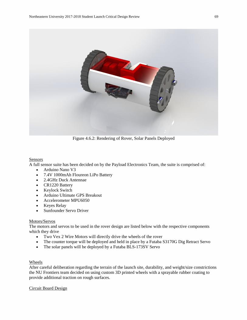
Northeastern University 2017-2018 Student Launch Critical Design Review 69
Figure 4.6.2: Rendering of Rover, Solar Panels Deployed
Sensors A full sensor suite has been decided on by the Payload Electronics Team, the suite is comprised of:
Arduino Nano V3
7.4V 1000mAh Floureon LiPo Battery
2.4GHz Duck Antennae
CR1220 Battery
Keylock Switch
Arduino Ultimate GPS Breakout
Accelerometer MPU6050
Keyes Relay
Sunfounder Servo Driver
Motors/Servos The motors and servos to be used in the rover design are listed below with the respective components
which they drive Two Vex 2 Wire Motors will directly drive the wheels of the rover
The counter torque will be deployed and held in place by a Futaba S3170G Dig Retract Servo
The solar panels will be deployed by a Futaba BLS-173SV Servo
Wheels After careful deliberation regarding the terrain of the launch site, durability, and weight/size constrictions
the NU Frontiers team decided on using custom 3D printed wheels with a sprayable rubber coating to
provide additional traction on rough surfaces. Circuit Board Design

Northeastern University 2017-2018 Student Launch Critical Design Review 70
As highlighted in the drawings section of the CDR, the PCB design for the NU Frontiers rover has been
completed and is in its final form. The PCB will allow for maximization of space, optimization of
soldering connections, and will reduce the chance of solder bridges which would be a failure mode if the
team used a proto board instead Mission Plan The mission plan for the NU Frontiers Rover has been clearly defined in the CDR. Ejection Plan The ejection plan for the NU Frontiers Rover, utilizing the PES ejection system has been clearly defined
in the CDR.
4.7. Payload Electrical Drawings and Dimensions Included in this section is the Fritzing diagram and PCB schematic for the NU-Frontiers Rover.
Figure 4.7.1: Fritzing diagram for NU-Frontiers Rover
Not seen above:
2x 7.4v LiPo connected in parallel to provide a redundant power source
1x Keylock switch connected in series to circuit, to be armed on pad
The above schematic is indicative of the final PCB design; all hookups will be identical for the final
design. Switches and wires will be separate from this design, mounted on the rover itself and wired into
the PCB.

Northeastern University 2017-2018 Student Launch Critical Design Review 71
The Fritzing software was used to design the payload layout. As Fritzing is a relatively new software,
there were some hurdles to overcome. Especially the DRC (Design Rule Checks) for the PCB design
were carefully check to make sure that no wires crossed or created shorts.
After several attempts, some utilizing the Autoroute functionality provided with the Fritzing software, the
team determined that it would best to manually route all connections.
Screw holes were placed on the outside of the PCB; it is the team’s intention to mount the PCB directly
within a side of the rover.
Figure 4.7.2: Initial PCB layout, based off autoroute functionality within the Fritzing software

Northeastern University 2017-2018 Student Launch Critical Design Review 72
Figure 4.7.3: Final PCB layout, manually routed with added via connections
4.8. Payload Block Diagrams The diagram below describes the connections between the different components used in the PES, NUFR
and ground station and the connections that are made between these components.
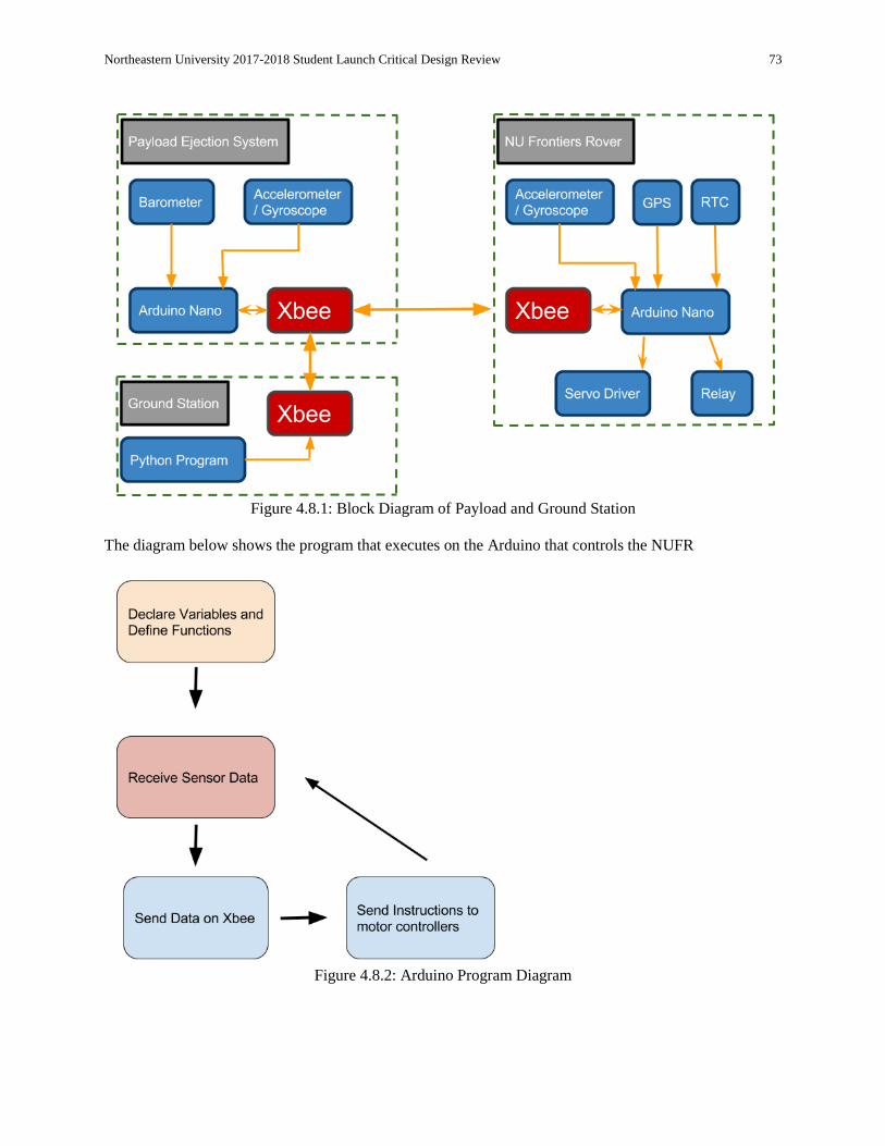
Northeastern University 2017-2018 Student Launch Critical Design Review 73
Figure 4.8.1: Block Diagram of Payload and Ground Station
The diagram below shows the program that executes on the Arduino that controls the NUFR
Figure 4.8.2: Arduino Program Diagram

Northeastern University 2017-2018 Student Launch Critical Design Review 74
4.9. Payload Battery and Power Consumption The NU Frontiers Rover (NUFR) will be powered by two 7.4V 1000 mAh li-po batteries connected in
parallel to increase the current for use by the motors powering the drive system. This gives a total of 2000
mAh of total power for the rover. The Payload Ejection System will also be powered by an additional two
identical 7.4V 100mAh Li-Po batteries.
Figure 4.9.1: 7.4V 1000mAh Li-Po
Table 4.9.1: Device Listing and Power Consumptions
Device Power Consumption
Xbee 1W
Arduino Nano 0.6W
GPS 0.1 W
Each battery is capable of supplying 7.4 Watt hours of power, with 2 batteries for a total power of 14.8
Watt hours. This means that the electronics in the PES can operate for approximately 6 hours before
power becomes a concern for the payload deployment phase of the flight.
4.10. Switch and Indicator Wattage and Location In order to arm the rover, a keylock switch will be used. The rover will be armed on the pad via a hole in
the body tube of the launch vehicle.
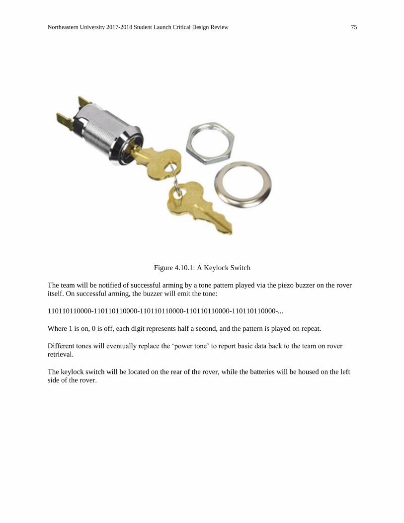
Northeastern University 2017-2018 Student Launch Critical Design Review 75
Figure 4.10.1: A Keylock Switch
The team will be notified of successful arming by a tone pattern played via the piezo buzzer on the rover
itself. On successful arming, the buzzer will emit the tone: 110110110000-110110110000-110110110000-110110110000-110110110000-... Where 1 is on, 0 is off, each digit represents half a second, and the pattern is played on repeat. Different tones will eventually replace the ‘power tone’ to report basic data back to the team on rover
retrieval. The keylock switch will be located on the rear of the rover, while the batteries will be housed on the left
side of the rover.
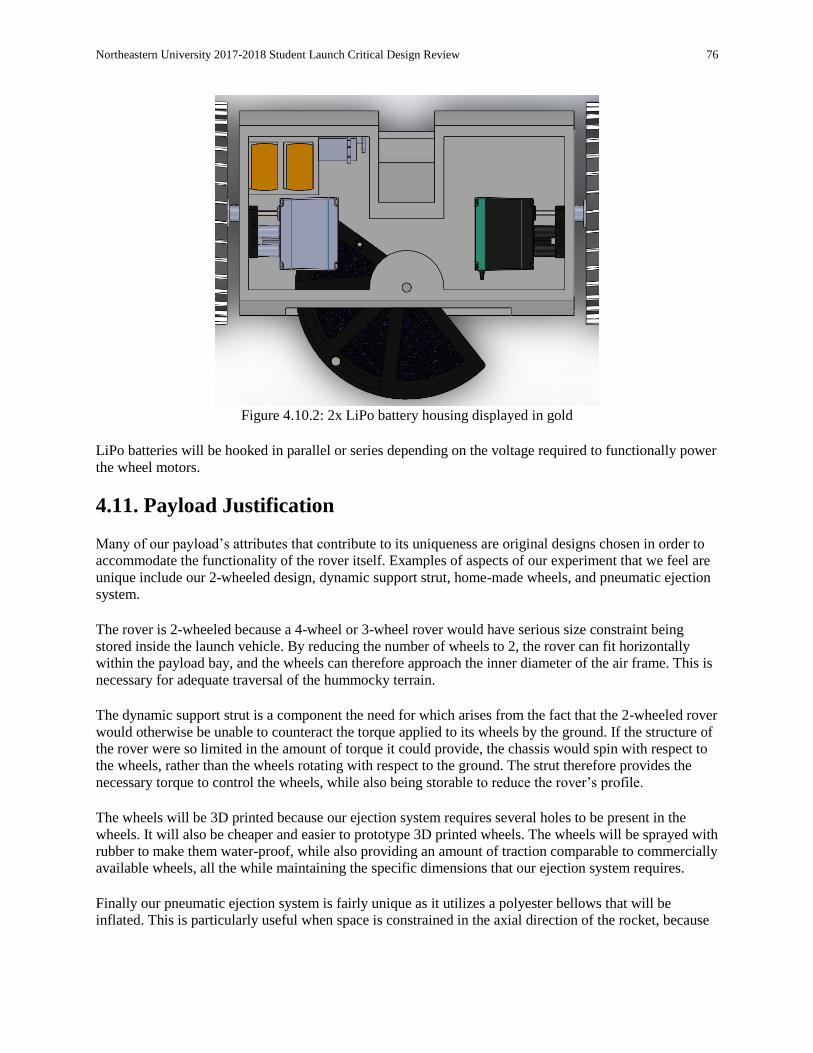
Northeastern University 2017-2018 Student Launch Critical Design Review 76
Figure 4.10.2: 2x LiPo battery housing displayed in gold
LiPo batteries will be hooked in parallel or series depending on the voltage required to functionally power
the wheel motors.
4.11. Payload Justification Many of our payload’s attributes that contribute to its uniqueness are original designs chosen in order to
accommodate the functionality of the rover itself. Examples of aspects of our experiment that we feel are
unique include our 2-wheeled design, dynamic support strut, home-made wheels, and pneumatic ejection
system. The rover is 2-wheeled because a 4-wheel or 3-wheel rover would have serious size constraint being
stored inside the launch vehicle. By reducing the number of wheels to 2, the rover can fit horizontally
within the payload bay, and the wheels can therefore approach the inner diameter of the air frame. This is
necessary for adequate traversal of the hummocky terrain. The dynamic support strut is a component the need for which arises from the fact that the 2-wheeled rover
would otherwise be unable to counteract the torque applied to its wheels by the ground. If the structure of
the rover were so limited in the amount of torque it could provide, the chassis would spin with respect to
the wheels, rather than the wheels rotating with respect to the ground. The strut therefore provides the
necessary torque to control the wheels, while also being storable to reduce the rover’s profile. The wheels will be 3D printed because our ejection system requires several holes to be present in the
wheels. It will also be cheaper and easier to prototype 3D printed wheels. The wheels will be sprayed with
rubber to make them water-proof, while also providing an amount of traction comparable to commercially
available wheels, all the while maintaining the specific dimensions that our ejection system requires. Finally our pneumatic ejection system is fairly unique as it utilizes a polyester bellows that will be
inflated. This is particularly useful when space is constrained in the axial direction of the rocket, because

Northeastern University 2017-2018 Student Launch Critical Design Review 77
most other ejection methods require as much physical space as the rover in order to fully deploy it. A
pneumatic system, on the other hand, is compressible, possible to 25% of its expanded length.

Northeastern University 2017-2018 Student Launch Critical Design Review 78
5. Project Plan
5.1. Testing
5.1.1. Payload Tests
To verify the functionality of the payload we will need to perform tests that include radio range
and data tests; signal testing on the rover and payload ejection system; verifying the code
functionality on the rover, payload ejection system, and ground station; running the payload
components at both full power and idle power to find the battery life in both of these scenarios;
testing the ability for the payload to withstand the forces at separation, drogue deploy, main chute
deploy, and landing; the ability for the rover to drive on rough terrain; finally, the ability of the
solar panels to deploy.
5.1.2. Rover Test Plans
Radio Communications Testing
A ground station and basic payload test were constructed with the following parameters
o Ground Station
USB Connection to Laptop computer
XBEE Pro 60mW
o Payload
Arduino Nano V3
XBEE Pro 60mW
7.4V 1000mAh LiPo
o During this test the ground station was placed at a set spot with linear sight on the
payload, packets were then transmitted from the payload device to the ground
station with various distances (NOTE this was done in an urban environment,
buildings impacted signal strength) signal reception tests were as follows
10m - Signal Reception
30m - Signal Reception
50m - Signal Reception
70m - Signal Reception
100m - Signal Reception
150m - Signal Reception
200m - Spotty Signal Reception (1 packets per ~1s)
250m - Spotty Signal Reception (1 packet per ~3s)
300m - Little to no Signal Reception (1 packet per ~20+ s)
A basic “dummy” payload was loaded into the subscale launch vehicle and a packet
transmit/reception test was conducted with the following parameters using a ground
station

Northeastern University 2017-2018 Student Launch Critical Design Review 79
o Ground Station
USB Connection to Laptop computer
XBEE Pro 60mW
o Payload
XBEE pro 60mW
7.4V 1000mAh LiPo
BMP180 Altimeter/Barometer Sensor
Arduino Nano V3
Accelerometer
o During this test the NU Frontiers sub-scale rocket was launched to an altitude of
2400 ft, during launch the “dummy” payload attempted to transmit altitude, and
accelerometer values. Transmission was completely lost at 2100 ft, with packets
being dropped starting around 1000 ft. The team decided to implement a higher
powered XBEE for the final design.
o Additionally, a signal transmission from the ground station was tested,
unfortunately this failed repeatedly until about 100 yards from the rover, where
signal was found and the transmission was received.
Battery Duration Testing We plan to test the duration that the batteries, in both the payload ejection system and the
rover, will last when under full load and idle pre-launch load.
o Ground Station
USB Connection to Laptop computer
XBEE Pro S2C
o Payload Ejection System (PES)
Arduino Nano V3
XBEE Pro S2C
2x 7.4V 1000mAh LiPo
BMP180 Barometer
Valve
o NU Frontiers Rover (NUFR)
Arduino Nano V3
XBEE Pro S2C
2x 7.4V 1000mAh LiPo
Accelerometer/Gyroscope
2x Vex Motors
2x Servos
Real Time Clock
GPS module
Servo Driver
o During this test we will run the system at idle and at full power draw to see how
long the systems are able to operate. This test will be considered a success if we
are able to determine the duration that the payload can operate on a fully charged
set of batteries.
o It is necessary to know this information on the battery duration to determine if we
will need to modify the payload to function after the required minimum of 1 hour
on the launch pad, with safety margin and power for deployment and roving.

Northeastern University 2017-2018 Student Launch Critical Design Review 80
5.2. Requirements Compliance
Verification Plan
Table 5.2.1 : Verification Plan
Number NASA Derived Requirement Requirement Completion
Plan Verification
1.1 Students on the team will do 100% of the
project, including design, construction, written
reports, presentations, and flight preparation
with the exception of assembling the motors
and handling black powder or any variant of
ejection charges, or preparing and installing
electric matches (to be done by the team’s
mentor).
Northeastern University’s
Chapter of AIAA takes pride in
exposing students to hands-on
engagement. Students in the
NASA USLI Competition will
have taken initiative and
leadership in the execution of
this project with the close
supervision of our mentor.
Self-Evaluation of
student involvement at
milestones
1.2 The team will provide and maintain a project
plan to include, but not limited to the following
items: project milestones, budget and
community support, checklists, personnel
assigned, educational engagement events, and
risks and mitigations.
The Northeastern University
Team has several members
committed to creating and
monitoring plans, a schedule,
and a budget to ensure these
requirements are met.
Periodic review and
evaluation of progress
relating to
aforementioned
requirements
1.3 Foreign National (FN) team members must be
identified by the Preliminary Design Review
(PDR) and may or may not have access to
certain activities during launch week due to
security restrictions. In addition, FN’s may be
separated from their team during these
activities.
There are no FN team members
on the Northeastern University
team.
Verified
1.4 The team must identify all team members
attending launch week activities by the Critical
Design Review (CDR). Team members will
include:
The team members attending
launch week activities have been
determined and notified.
N/A
1.4.1. Students actively engaged in the project
throughout the entire year. Will be verified by attendance
record, engagement and
contribution.
N/A
1.4.2. One mentor (see requirement 1.14). Identified as Robert DeHate. Verified
1.4.3. No more than two adult educators. N/A N/A
1.5 The team will engage a minimum of 200
participants in educational, hands-on science,
technology, engineering, and mathematics
(STEM) activities, as defined in the
Educational Engagement Activity Report, by
FRR. An educational engagement activity
report will be completed and submitted within
two weeks after completion of an event. A
sample of the educational engagement activity
report can be found on page 31 of the
handbook. To satisfy this requirement, all
events must occur between project acceptance
The team has a dedicated STEM
outreach coordinator who
organizes STEM education
events in conjunction with
Northeastern University’s Center
for STEM education such as
field trips for local high schools,
science fairs, and paper rockets
demonstrations. This STEM
coordinator will also be
responsible for submitting
engagement activity reports.
Engagement will be
measured by attendance
by K-12 students and
counted only if 2 or more
team members attend the
event.
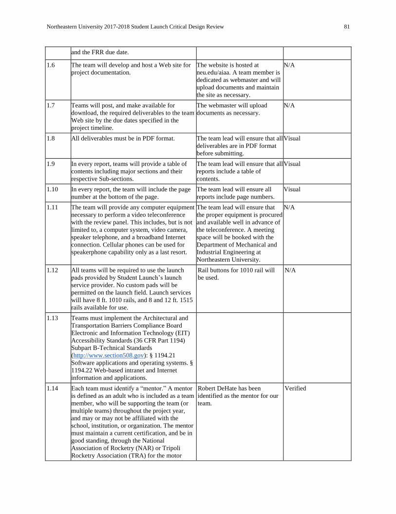
Northeastern University 2017-2018 Student Launch Critical Design Review 81
and the FRR due date.
1.6 The team will develop and host a Web site for
project documentation. The website is hosted at
neu.edu/aiaa. A team member is
dedicated as webmaster and will
upload documents and maintain
the site as necessary.
N/A
1.7 Teams will post, and make available for
download, the required deliverables to the team
Web site by the due dates specified in the
project timeline.
The webmaster will upload
documents as necessary. N/A
1.8 All deliverables must be in PDF format. The team lead will ensure that all
deliverables are in PDF format
before submitting.
Visual
1.9 In every report, teams will provide a table of
contents including major sections and their
respective Sub-sections.
The team lead will ensure that all
reports include a table of
contents.
Visual
1.10 In every report, the team will include the page
number at the bottom of the page. The team lead will ensure all
reports include page numbers. Visual
1.11 The team will provide any computer equipment
necessary to perform a video teleconference
with the review panel. This includes, but is not
limited to, a computer system, video camera,
speaker telephone, and a broadband Internet
connection. Cellular phones can be used for
speakerphone capability only as a last resort.
The team lead will ensure that
the proper equipment is procured
and available well in advance of
the teleconference. A meeting
space will be booked with the
Department of Mechanical and
Industrial Engineering at
Northeastern University.
N/A
1.12 All teams will be required to use the launch
pads provided by Student Launch’s launch
service provider. No custom pads will be
permitted on the launch field. Launch services
will have 8 ft. 1010 rails, and 8 and 12 ft. 1515
rails available for use.
Rail buttons for 1010 rail will
be used. N/A
1.13 Teams must implement the Architectural and
Transportation Barriers Compliance Board
Electronic and Information Technology (EIT)
Accessibility Standards (36 CFR Part 1194)
Subpart B-Technical Standards
(http://www.section508.gov): § 1194.21
Software applications and operating systems. §
1194.22 Web-based intranet and Internet
information and applications.
1.14 Each team must identify a “mentor.” A mentor
is defined as an adult who is included as a team
member, who will be supporting the team (or
multiple teams) throughout the project year,
and may or may not be affiliated with the
school, institution, or organization. The mentor
must maintain a current certification, and be in
good standing, through the National
Association of Rocketry (NAR) or Tripoli
Rocketry Association (TRA) for the motor
Robert DeHate has been
identified as the mentor for our
team.
Verified
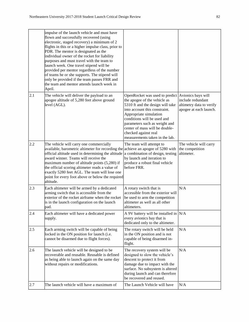
Northeastern University 2017-2018 Student Launch Critical Design Review 82
impulse of the launch vehicle and must have
flown and successfully recovered (using
electronic, staged recovery) a minimum of 2
flights in this or a higher impulse class, prior to
PDR. The mentor is designated as the
individual owner of the rocket for liability
purposes and must travel with the team to
launch week. One travel stipend will be
provided per mentor regardless of the number
of teams he or she supports. The stipend will
only be provided if the team passes FRR and
the team and mentor attends launch week in
April.
2.1 The vehicle will deliver the payload to an
apogee altitude of 5,280 feet above ground
level (AGL).
OpenRocket was used to predict
the apogee of the vehicle as
5310 ft and the design will take
into account this constraint.
Appropriate simulation
conditions will be used and
parameters such as weight and
center of mass will be double-
checked against real
measurements taken in the lab.
Avionics bays will
include redundant
altimetry data to verify
apogee at each launch.
2.2 The vehicle will carry one commercially
available, barometric altimeter for recording the
official altitude used in determining the altitude
award winner. Teams will receive the
maximum number of altitude points (5,280) if
the official scoring altimeter reads a value of
exactly 5280 feet AGL. The team will lose one
point for every foot above or below the required
altitude.
The team will attempt to
achieve an apogee of 5280 with
a combination of design, testing
by launch and iteration to
produce a robust final vehicle
before FRR.
The vehicle will carry
the competition
altimeter.
2.3 Each altimeter will be armed by a dedicated
arming switch that is accessible from the
exterior of the rocket airframe when the rocket
is in the launch configuration on the launch
pad.
A rotary switch that is
accessible from the exterior will
be used to arm the competition
altimeter as well as all other
altimeters.
N/A
2.4 Each altimeter will have a dedicated power
supply. A 9V battery will be installed in
every avionics bay that is
dedicated only to the altimeter.
N/A
2.5 Each arming switch will be capable of being
locked in the ON position for launch (i.e.
cannot be disarmed due to flight forces).
The rotary switch will be held
in the ON position and is not
capable of being disarmed in-
flight.
N/A
2.6 The launch vehicle will be designed to be
recoverable and reusable. Reusable is defined
as being able to launch again on the same day
without repairs or modifications.
The recovery system will be
designed to slow the vehicle’s
descent to protect it from
damage due to impact with the
surface. No subsystem is altered
during launch and can therefore
be recovered and reused.
N/A
2.7 The launch vehicle will have a maximum of The Launch Vehicle will have N/A
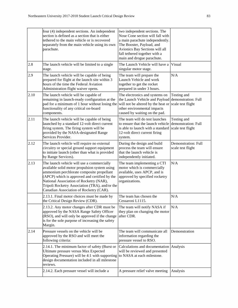
Northeastern University 2017-2018 Student Launch Critical Design Review 83
four (4) independent sections. An independent
section is defined as a section that is either
tethered to the main vehicle or is recovered
separately from the main vehicle using its own
parachute.
two independent sections. The
Nose Cone section will fall with
a main parachute independently.
The Booster, Payload, and
Avionics Bay Sections will all
fall tethered together with a
main and drogue parachute.
2.8 The launch vehicle will be limited to a single
stage. The Launch Vehicle will have a
singular motor stage. Visual
2.9 The launch vehicle will be capable of being
prepared for flight at the launch site within 3
hours of the time the Federal Aviation
Administration flight waiver opens.
The team will prepare the
Launch Vehicle and work
together to get the rocket
prepared in under 3 hours.
N/A
2.10 The launch vehicle will be capable of
remaining in launch-ready configuration at the
pad for a minimum of 1 hour without losing the
functionality of any critical on-board
components.
The electronics and systems on
the Launch Vehicle and Payload
will not be altered by the heat or
other environmental impacts
caused by waiting on the pad.
Testing and
demonstration: Full
scale test flight
2.11 The launch vehicle will be capable of being
launched by a standard 12-volt direct current
firing system. The firing system will be
provided by the NASA-designated Range
Services Provider.
The team will do test launches
to ensure that the launch vehicle
is able to launch with a standard
12-volt direct current firing
system.
Testing and
demonstration: Full
scale test flight
2.12 The launch vehicle will require no external
circuitry or special ground support equipment
to initiate launch (other than what is provided
by Range Services).
During the design and build
process the team will ensure
that the launch vehicle is
independently initiated.
Demonstration: Full
scale test flight
2.13 The launch vehicle will use a commercially
available solid motor propulsion system using
ammonium perchlorate composite propellant
(APCP) which is approved and certified by the
National Association of Rocketry (NAR),
Tripoli Rocketry Association (TRA), and/or the
Canadian Association of Rocketry (CAR).
The team implementing a CTI
motor which is commercially
available, uses APCP, and is
approved by specified rocketry
organizations.
N/A
2.13.1. Final motor choices must be made by
the Critical Design Review (CDR). The team has chosen the
Cessaroni L1115. N/A
2.13.2. Any motor changes after CDR must be
approved by the NASA Range Safety Officer
(RSO), and will only be approved if the change
is for the sole purpose of increasing the safety
Margin.
The team will notify NASA if
they plan on changing the motor
after CDR.
N/A
2.14 Pressure vessels on the vehicle will be
approved by the RSO and will meet the
following criteria:
The team will communicate all
information regarding the
pressure vessel to RSO.
Demonstration
2.14.1. The minimum factor of safety (Burst or
Ultimate pressure versus Max Expected
Operating Pressure) will be 4:1 with supporting
design documentation included in all milestone
reviews.
Calculations and documentation
will be reviewed and presented
to NASA at each milestone.
Analysis
2.14.2. Each pressure vessel will include a A pressure relief valve meeting Analysis

Northeastern University 2017-2018 Student Launch Critical Design Review 84
pressure relief valve that sees the full pressure
of the valve that is capable of withstanding the
maximum pressure and flow rate of the tank.
said requirements will be
identified and used in the design
of the system.
2.14.3. Full pedigree of the tank will be
described, including the application for which
the tank was designed, and the history of the
tank, including the number of pressure cycles
put on the tank, by whom, and when.
The team will ascertain and
present this information to
NASA.
N/A
2.15 The total impulse provided by a College and/or
University launch vehicle will not exceed 5,120
Newton-seconds (L-class).
L1395-BS made by CTI, where
the specifications say that it will
not exceed 5,120 Newton-
seconds.
The specifications
provided by the
manufacturer will verify.
2.16 The launch vehicle will have a minimum static
stability margin of 2.0 at the point of rail exit.
Rail exit is defined at the point where the
forward rail button loses contact with the rail.
The static stability margin was
calculated using OpenRocket. A
stability of 3.3 is given.
Analysis
2.17 The launch vehicle will accelerate to a
minimum velocity of 52 fps at rail exit. The velocity at rail exit was
calculated using OpenRocket.
69.9 ft/s is given.
Analysis
2.18 All teams will successfully launch and recover
a subscale model of their rocket prior to CDR.
Subscales are not required to be high power
rockets.
The original subscale rocket
launch was not considered
successful. Therefore a second
subscale was launched and was
successful.
Demonstration
2.18.1. The subscale model should resemble
and perform as similarly as possible to the full-
scale model; however, the full-scale will not be
used as the subscale model.
The subscale model was
constructed such that it would
perform similarly to the full
scale model.
Demonstration
2.18.2. The subscale model will carry an
altimeter capable of reporting the model’s
apogee altitude.
The subscale contained
PerfectFlite Stratologgers to
record the model’s apogee
altitude.
Demonstration
2.19 All teams will successfully launch and recover
their full-scale rocket prior to FRR in its final
flight configuration. The rocket flown at FRR
must be the same rocket to be flown on launch
day. The purpose of the full-scale
demonstration flight is to demonstrate the
launch vehicle’s stability, structural integrity,
recovery systems, and the team’s ability to
prepare the launch vehicle for flight. A
successful flight is defined as a launch in which
all hardware is functioning properly (i.e. drogue
chute at apogee, main chute at a lower altitude,
functioning tracking devices, etc.). The
following criteria must be met during the full-
scale demonstration flight:
The team will construct and
launch a full scale launch
vehicle prior to FRR. This
launch will demonstrate all
required criteria.
Demonstration
2.19.1. The vehicle and recovery system will
have functioned as designed. The flight events and launch
vehicle will be inspected to
check that it has functioned as
designed.
Inspection

Northeastern University 2017-2018 Student Launch Critical Design Review 85
2.19.2. The payload does not have to be flown
during the full-scale test flight. The following
requirements still apply:
N/A N/A
2.19.2.1. If the payload is not flown, mass
simulators will be used to simulate the payload
mass.
A simulated mass equal to the
mass of the payload, 2.8 kg,
will be used in test launches if
the payload is not flown.
N/A
2.19.2.1.1. The mass simulators will be located
in the same approximate location on the rocket
as the missing payload mass.
In the case a simulated mass is
used in place of the payload, the
mass will be in the approximate
location of the missing payload.
N/A
2.19.3. If the payload changes the external
surfaces of the rocket (such as with camera
housings or external probes) or manages the
total energy of the vehicle, those systems will
be active during the full-scale demonstration
flight.
External surface changes and
total energy management will
be implemented during the full-
scale demonstration flight if
applicable.
N/A
2.19.4. The full-scale motor does not have to be
flown during the full-scale test flight. However,
it is recommended that the full-scale motor be
used to demonstrate full flight readiness and
altitude verification. If the full-scale motor is
not flown during the full-scale flight, it is
desired that the motor simulates, as closely as
possible, the predicted maximum velocity and
maximum acceleration of the launch day flight.
The full scale motor or a similar
motor will be used in the full
flight readiness test to simulate
the predicted flight data of the
launch day flight.
N/A
2.19.5. The vehicle must be flown in its fully
ballasted configuration during the full-scale test
flight. Fully ballasted refers to the same amount
of ballast that will be flown during the launch
day flight. Additional ballast may not be added
without a re-flight of the full-scale launch
vehicle.
The vehicle will be flown in its
fully ballasted configuration
during the full-scale test flight.
If additional ballast is desired,
another full-scale test will be
flown with the additional ballast
added
N/A
2.19.6. After successfully completing the full-
scale demonstration flight, the launch vehicle or
any of its components will not be modified
without the concurrence of the NASA Range
Safety Officer (RSO).
No changes will be made to the
launch vehicle or its
componentes after a successful
full-scale flight without the
concurrence of the NASA
Range Safety Officer
N/A
2.19.7. Full scale flights must be completed by
the start of FRRs (March 6th, 2018). If the
Student Launch office determines that a re-
flight is necessary, then an extension to March
28th, 2018 will be granted. This extension is
only valid for re-flights; not first-time flights.
A full scale flight will be
completed by March 6th, 2018.
If required by NASA, a re-flight
will be flown by March 28th,
2018
N/A
2.20 Any structural protuberance on the rocket will
be located aft of the burnout center of gravity. Any structural protuberance on
the rocket will be located aft of
the burnout center of gravity.
Analysis/Inspection
2.21 Vehicle Prohibitions
2.21.1. The launch vehicle will not utilize
forward canards. The team will not put forward
canards on the launch vehicle. Visual
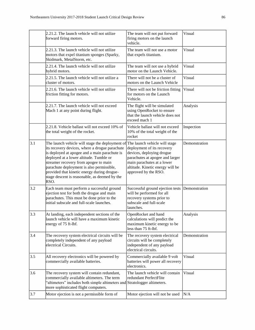
Northeastern University 2017-2018 Student Launch Critical Design Review 86
2.21.2. The launch vehicle will not utilize
forward firing motors. The team will not put forward
firing motors on the launch
vehicle.
Visual
2.21.3. The launch vehicle will not utilize
motors that expel titanium sponges (Sparky,
Skidmark, MetalStorm, etc.
The team will not use a motor
that expels titanium. Visual
2.21.4. The launch vehicle will not utilize
hybrid motors. The team will not use a hybrid
motor on the Launch Vehicle. Visual
2.21.5. The launch vehicle will not utilize a
cluster of motors. There will not be a cluster of
motors on the Launch Vehicle Visual
2.21.6. The launch vehicle will not utilize
friction fitting for motors. There will not be friction fitting
for motors on the Launch
Vehicle.
Visual
2.21.7. The launch vehicle will not exceed
Mach 1 at any point during flight. The flight will be simulated
using OpenRocket to ensure
that the launch vehicle does not
exceed mach 1
Analysis
2.21.8. Vehicle ballast will not exceed 10% of
the total weight of the rocket. Vehicle ballast will not exceed
10% of the total weight of the
rocket
Inspection
3.1 The launch vehicle will stage the deployment of
its recovery devices, where a drogue parachute
is deployed at apogee and a main parachute is
deployed at a lower altitude. Tumble or
streamer recovery from apogee to main
parachute deployment is also permissible,
provided that kinetic energy during drogue-
stage descent is reasonable, as deemed by the
RSO.
The launch vehicle will stage
deployment of its recovery
devices, deploying drogue
parachutes at apogee and larger
main parachutes at a lower
altitude. Kinetic energy will be
approved by the RSO.
Demonstration
3.2 Each team must perform a successful ground
ejection test for both the drogue and main
parachutes. This must be done prior to the
initial subscale and full-scale launches.
Successful ground ejection tests
will be performed for all
recovery systems prior to
subscale and full-scale
launches.
Demonstration
3.3 At landing, each independent sections of the
launch vehicle will have a maximum kinetic
energy of 75 ft-lbf.
OpenRocket and hand
calculations will predict the
maximum kinetic energy to be
less than 75 ft-lbf.
Analysis
3.4 The recovery system electrical circuits will be
completely independent of any payload
electrical Circuits.
The recovery system electrical
circuits will be completely
independent of any payload
electrical circuits.
Demonstration
3.5 All recovery electronics will be powered by
commercially available batteries. Commercially available 9 volt
batteries will power all recovery
electronics.
Visual
3.6 The recovery system will contain redundant,
commercially available altimeters. The term
“altimeters” includes both simple altimeters and
more sophisticated flight computers.
The launch vehicle will contain
redundant PerfectFlite
Stratologger altimeters.
Visual
3.7 Motor ejection is not a permissible form of Motor ejection will not be used N/A
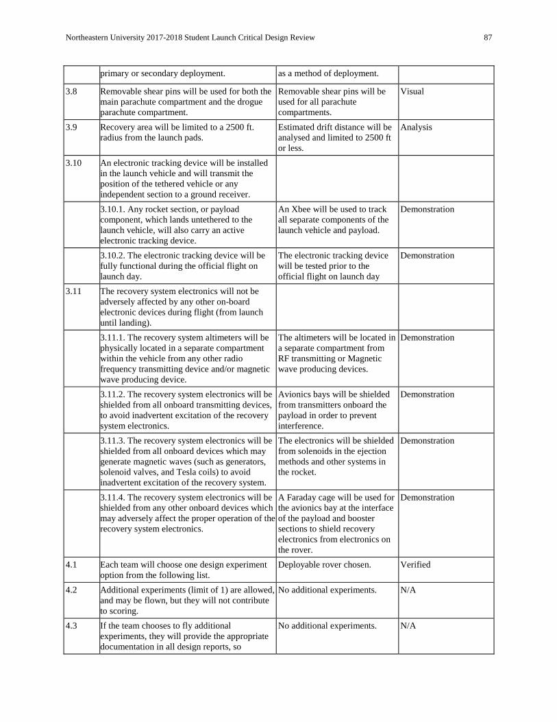
Northeastern University 2017-2018 Student Launch Critical Design Review 87
primary or secondary deployment. as a method of deployment.
3.8 Removable shear pins will be used for both the
main parachute compartment and the drogue
parachute compartment.
Removable shear pins will be
used for all parachute
compartments.
Visual
3.9 Recovery area will be limited to a 2500 ft.
radius from the launch pads. Estimated drift distance will be
analysed and limited to 2500 ft
or less.
Analysis
3.10 An electronic tracking device will be installed
in the launch vehicle and will transmit the
position of the tethered vehicle or any
independent section to a ground receiver.
3.10.1. Any rocket section, or payload
component, which lands untethered to the
launch vehicle, will also carry an active
electronic tracking device.
An Xbee will be used to track
all separate components of the
launch vehicle and payload.
Demonstration
3.10.2. The electronic tracking device will be
fully functional during the official flight on
launch day.
The electronic tracking device
will be tested prior to the
official flight on launch day
Demonstration
3.11 The recovery system electronics will not be
adversely affected by any other on-board
electronic devices during flight (from launch
until landing).
3.11.1. The recovery system altimeters will be
physically located in a separate compartment
within the vehicle from any other radio
frequency transmitting device and/or magnetic
wave producing device.
The altimeters will be located in
a separate compartment from
RF transmitting or Magnetic
wave producing devices.
Demonstration
3.11.2. The recovery system electronics will be
shielded from all onboard transmitting devices,
to avoid inadvertent excitation of the recovery
system electronics.
Avionics bays will be shielded
from transmitters onboard the
payload in order to prevent
interference.
Demonstration
3.11.3. The recovery system electronics will be
shielded from all onboard devices which may
generate magnetic waves (such as generators,
solenoid valves, and Tesla coils) to avoid
inadvertent excitation of the recovery system.
The electronics will be shielded
from solenoids in the ejection
methods and other systems in
the rocket.
Demonstration
3.11.4. The recovery system electronics will be
shielded from any other onboard devices which
may adversely affect the proper operation of the
recovery system electronics.
A Faraday cage will be used for
the avionics bay at the interface
of the payload and booster
sections to shield recovery
electronics from electronics on
the rover.
Demonstration
4.1 Each team will choose one design experiment
option from the following list. Deployable rover chosen. Verified
4.2 Additional experiments (limit of 1) are allowed,
and may be flown, but they will not contribute
to scoring.
No additional experiments. N/A
4.3 If the team chooses to fly additional
experiments, they will provide the appropriate
documentation in all design reports, so
No additional experiments. N/A
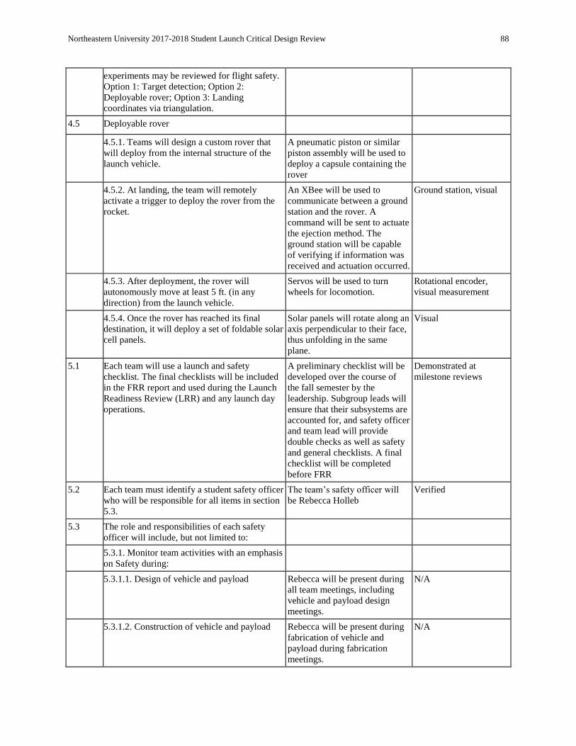
Northeastern University 2017-2018 Student Launch Critical Design Review 88
experiments may be reviewed for flight safety.
Option 1: Target detection; Option 2:
Deployable rover; Option 3: Landing
coordinates via triangulation.
4.5 Deployable rover
4.5.1. Teams will design a custom rover that
will deploy from the internal structure of the
launch vehicle.
A pneumatic piston or similar
piston assembly will be used to
deploy a capsule containing the
rover
4.5.2. At landing, the team will remotely
activate a trigger to deploy the rover from the
rocket.
An XBee will be used to
communicate between a ground
station and the rover. A
command will be sent to actuate
the ejection method. The
ground station will be capable
of verifying if information was
received and actuation occurred.
Ground station, visual
4.5.3. After deployment, the rover will
autonomously move at least 5 ft. (in any
direction) from the launch vehicle.
Servos will be used to turn
wheels for locomotion. Rotational encoder,
visual measurement
4.5.4. Once the rover has reached its final
destination, it will deploy a set of foldable solar
cell panels.
Solar panels will rotate along an
axis perpendicular to their face,
thus unfolding in the same
plane.
Visual
5.1 Each team will use a launch and safety
checklist. The final checklists will be included
in the FRR report and used during the Launch
Readiness Review (LRR) and any launch day
operations.
A preliminary checklist will be
developed over the course of
the fall semester by the
leadership. Subgroup leads will
ensure that their subsystems are
accounted for, and safety officer
and team lead will provide
double checks as well as safety
and general checklists. A final
checklist will be completed
before FRR
Demonstrated at
milestone reviews
5.2 Each team must identify a student safety officer
who will be responsible for all items in section
5.3.
The team’s safety officer will
be Rebecca Holleb Verified
5.3 The role and responsibilities of each safety
officer will include, but not limited to:
5.3.1. Monitor team activities with an emphasis
on Safety during:
5.3.1.1. Design of vehicle and payload Rebecca will be present during
all team meetings, including
vehicle and payload design
meetings.
N/A
5.3.1.2. Construction of vehicle and payload Rebecca will be present during
fabrication of vehicle and
payload during fabrication
meetings.
N/A

Northeastern University 2017-2018 Student Launch Critical Design Review 89
5.3.1.3. Assembly of vehicle and payload Rebecca will be present during
assembly of vehicle and
payload during assembly
meetings.
N/A
5.3.1.4. Ground testing of vehicle and payload Rebecca will be present for all
ground tests. N/A
5.3.1.5. Sub-scale launch test(s) Rebecca will be present for all
sub scale launches. N/A
5.3.1.6. Full-scale launch test(s) Rebecca will be present for all
full scale launches. N/A
5.3.1.7. Launch day Rebecca will be present at
launch day. N/A
5.3.1.8. Recovery activities Rebecca will be present for
recovery activities. N/A
5.3.1.9. Educational Engagement Activities Rebecca will be present for
educational engagement
activities.
N/A
5.3.2. Implement procedures developed by the
team for construction, assembly, launch, and
recovery activities
Rebecca has assisted in the
formulation of these procedures
and will ensure they are
implemented.
Demonstration at ground
tests, launches and
internal performance
evaluations
5.3.3. Manage and maintain current revisions of
the team’s hazard analyses, failure modes
analyses, procedures, and MSDS/chemical
inventory data
Rebecca will work closely with
the club safety officers for
guidance with these matters
towards the end of properly
maintaining understanding of
the current hazards and failure
modes.
Demonstration in
milestone reviews and
internal reflections on
performance
5.3.4. Assist in the writing and development of
the team’s hazard analyses, failure modes
analyses, and procedures.
Rebecca contributes a great deal
to these sections. Verified
5.4 During test flights, teams will abide by the rules
and guidance of the local rocketry club’s RSO.
The allowance of certain vehicle configurations
and/or payloads at the NASA Student Launch
Initiative does not give explicit or implicit
authority for teams to fly those certain vehicle
configurations and/or payloads at other club
launches. Teams should communicate their
intentions to the local club’s President or
Prefect and RSO before attending any NAR or
TRA launch.
AIAA at Northeastern
University remains in good
communication with Central
Massachusetts Spacemodeling
Society (CMASS), NAR
chapter 464. We attend many
launches per season and have
good relationships with the
RSO.
Demonstration of
requirement verification
at test launches
5.5 Teams will abide by all rules set forth by the
FAA. Safety officer will be familiar
with FAA rules. Team will refer
to the club design safety
committee for FAA guidelines
and compliance
Review meeting with
design safety committee

Northeastern University 2017-2018 Student Launch Critical Design Review 90
Table 5.2.2 : Verification Plan Cont.
Requirement Justification Completion Plan Verification
Vehicle
Payload bay open to air and
unencumbered at landing Required for proper
payload deployment Payload section will be connected at
one end to recovery system while at
the other a charge will separate the
two sections, leaving the payload exit
open to the air.
Demonstration at
ground tests, subscale,
and full scale
launches
Payload undamaged by
deployment method Required for robust
payload deployment and
for reusability
Designs are constrained by ability to
protect payload consistently from
damage.
Simulation,
demonstration at
ground tests, subscale,
and full scale
launches
Payload deployment and
vehicle recovery system
supported by redundant
systems
Encouraged by internal
club policies and club
design safety committee
Altimeters will have redundant units;
ejection method will have backup and
fail-safe systems.
N/A
Ejection System and Payload Experiment
Payload ejection system is
robust and reliable so that
successful deployment occurs
every time
Required for reusability,
required for success at
competition
Ejection method will not be chaotic,
controlled designs only will be
considered.
Demonstration at
ground tests, subscale,
and full scale
launches
Ejection system and payload
shall not weigh more than 3
kg combined
Required for launch
vehicle design to ensure
apogee of 5280 ft
Simulation,
measurements
Proper safety precaution will
be taken when handling
pressurized gas
Specific to our
experiment and required
by handbook
Team members working with
pressurized gas will become familiar
with all guidelines and consult club
safety officers for guidance.
N/A
Payload capsule will fully
open upon deployment from
airframe
Required for safe
deployment of rover
without damage,
considered success
criteria of experiment
Systems of springs and latches will be
used to open the capsule and ensure it
stays open and is open enough for
payload clearance.
Demonstration at
ground tests, subscale,
and full scale
launches
Payload will deploy its
counter-torque support wheel
upon exiting the airframe
Considered success
criteria of experiment Support will be controlled by servo
which will be directed to deploy
support once exit is confirmed.
Demonstration at
ground tests, subscale,
and full scale
launches
Rover will be capable of
moving 5 ft away from rocket
and overcoming terrain
Internally derived
requirement to amend
handbook requirement
based on knowledge of
launch site terrain
Wheels will be designed and tested on
loose surface material. Demonstration at
ground tests, subscale,
and full scale
launches
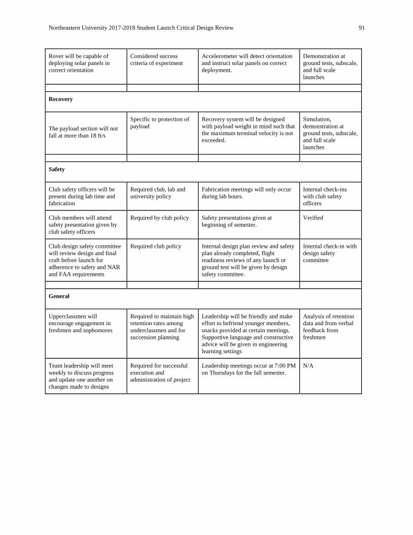
Northeastern University 2017-2018 Student Launch Critical Design Review 91
Rover will be capable of
deploying solar panels in
correct orientation
Considered success
criteria of experiment Accelerometer will detect orientation
and instruct solar panels on correct
deployment.
Demonstration at
ground tests, subscale,
and full scale
launches
Recovery
The payload section will not
fall at more than 18 ft/s
Specific to protection of
payload Recovery system will be designed
with payload weight in mind such that
the maximum terminal velocity is not
exceeded.
Simulation,
demonstration at
ground tests, subscale,
and full scale
launches
Safety
Club safety officers will be
present during lab time and
fabrication
Required club, lab and
university policy Fabrication meetings will only occur
during lab hours. Internal check-ins
with club safety
officers
Club members will attend
safety presentation given by
club safety officers
Required by club policy Safety presentations given at
beginning of semester. Verified
Club design safety committee
will review design and final
craft before launch for
adherence to safety and NAR
and FAA requirements
Required club policy Internal design plan review and safety
plan already completed, flight
readiness reviews of any launch or
ground test will be given by design
safety committee.
Internal check-in with
design safety
committee
General
Upperclassmen will
encourage engagement in
freshmen and sophomores
Required to maintain high
retention rates among
underclassmen and for
succession planning
Leadership will be friendly and make
effort to befriend younger members,
snacks provided at certain meetings.
Supportive language and constructive
advice will be given in engineering
learning settings
Analysis of retention
data and from verbal
feedback from
freshmen
Team leadership will meet
weekly to discuss progress
and update one another on
changes made to designs
Required for successful
execution and
administration of project
Leadership meetings occur at 7:00 PM
on Thursdays for the fall semester. N/A

Northeastern University 2017-2018 Student Launch Critical Design Review 92
5.3. Budgeting and Timeline Line Item Budget
Our line item budget for the spring semester is given below. Funding Plan
AIAA at NU has submitted requests for funding from multiple sources for the 2018 NASA University Student Launch Initiative. To cover material goods that will be used in the
development and construction of our full-scale rocket and payload, we have submitted a budget to
Northeastern’s Student Government Association (SGA). This money will become available to us in late
January, at which point we will purchase our materials. Until then, we have set aside provisional funds
from last semester to purchase high-priority materials such as fiberglass for body tube. For travel
expenses and STEM outreach related costs, we have applied for a grant of $3,000 from Northeastern’s
COE Scranton fund. For an additional source of funding, we will also apply to conduct a campaign on
Northeastern’s HuskyStarter crowdsourcing platform. The money from the Scranton Fund and
HuskyStarter will go towards transportation fees. We will present our project to SGA’s finance board and
follow their specified protocol in order to request funding for our budget. We have high confidence that
our request of $3,486 will be granted. Our next step for funding is applying to Northeastern’s
HuskyStarter. This crowdsourcing platform allows projects to be exposed to a community of thousands of
potential donors, as well as generates interest within the community. We will have to complete an online
application, after which, we will present a photo or video presentation to potential donors and document
the progress of our launch vehicle. We have been successful with HuskyStarter in the past, so we believe
we will get this funding as well. These sources will fully support our team’s financial needs through
completion of the project. Our expected travel expenses are listed below.
Table 5.3.1 : Travel Expenses
Item Vendor Price Quantity Cost
January 14th MDRA
Gas (1 car) Various $70 1 Car $70
Tolls (1 car) Various $52 1 Car $52
Hotel (1 room) Courtyard Marriott $100 1 Night $100
February 17th-18th MDRA
Gas (2 cars) Various $70 2 $140
Tolls (2 cars) Various $52 2 $104
Hotel (2 rooms) TBD $200 1 Night $200
Huntsville
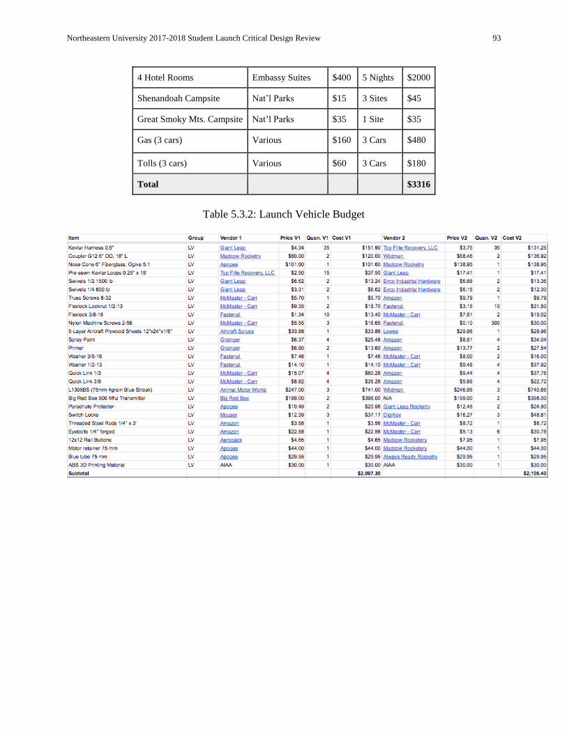
Northeastern University 2017-2018 Student Launch Critical Design Review 93
4 Hotel Rooms Embassy Suites $400 5 Nights $2000
Shenandoah Campsite Nat’l Parks $15 3 Sites $45
Great Smoky Mts. Campsite Nat’l Parks $35 1 Site $35
Gas (3 cars) Various $160 3 Cars $480
Tolls (3 cars) Various $60 3 Cars $180
Total $3316
Table 5.3.2: Launch Vehicle Budget

Northeastern University 2017-2018 Student Launch Critical Design Review 94
Table 5.3.3 : Payload Budget
Table 5.3.4 : Electronics Budget and Total
Table 5.3.5 : Project Schedule
Task Start Date Duration End Date
Winter Break 12/16/2017 23 1/8/2018
Fabricate Final Rover 1/9/2018 39 2/17/2018
CDR 1/5/2018 7 1/12/2018
*CDR Telecon 1/17/2018 1 1/18/2018
Ground Test Full Scale LV 2/12/2018 5 2/17/2018
Full Scale Test Launch 2/17/2018 1 2/18/2018
Test Launch Analysis 2/19/2018 2 2/21/2018
Update LV Design (if needed) 2/19/2018 4 2/23/2018
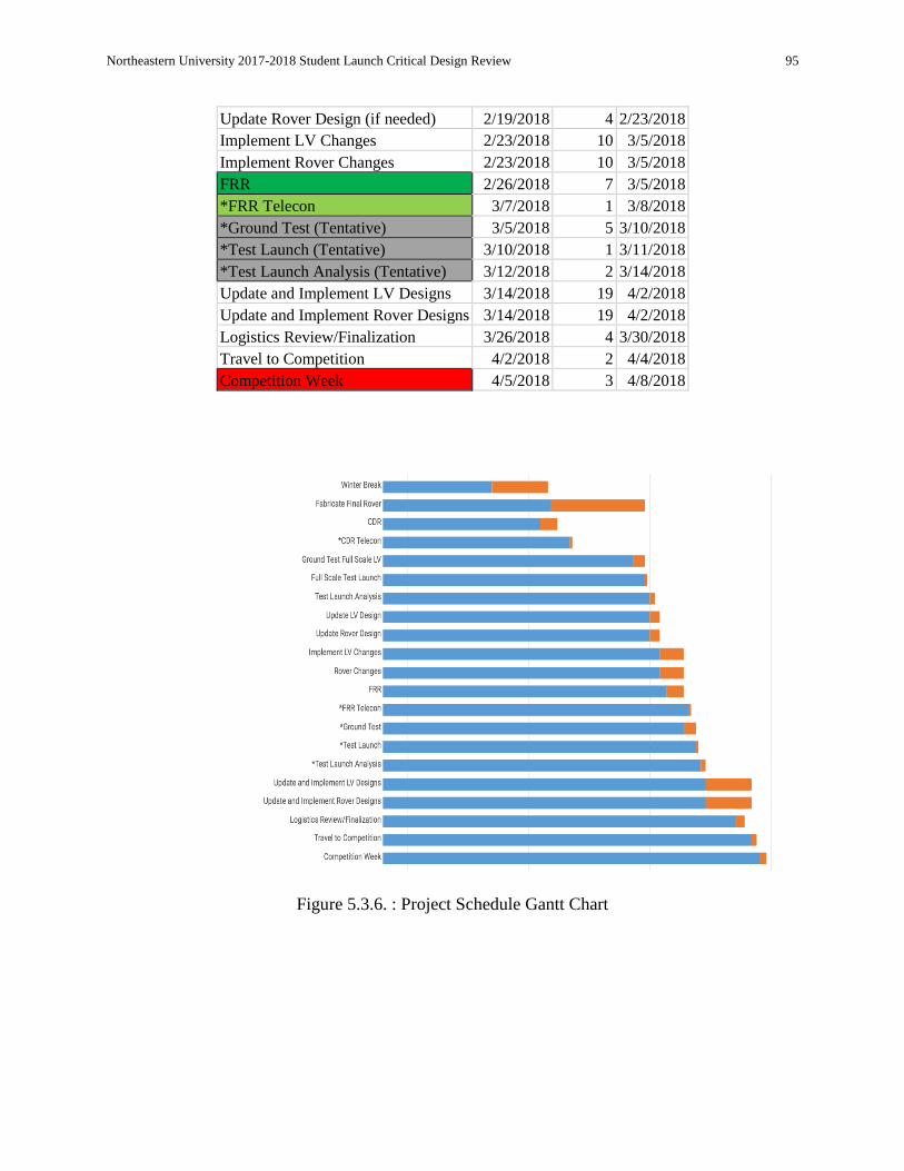
Northeastern University 2017-2018 Student Launch Critical Design Review 95
Update Rover Design (if needed) 2/19/2018 4 2/23/2018
Implement LV Changes 2/23/2018 10 3/5/2018
Implement Rover Changes 2/23/2018 10 3/5/2018
FRR 2/26/2018 7 3/5/2018
*FRR Telecon 3/7/2018 1 3/8/2018
*Ground Test (Tentative) 3/5/2018 5 3/10/2018
*Test Launch (Tentative) 3/10/2018 1 3/11/2018
*Test Launch Analysis (Tentative) 3/12/2018 2 3/14/2018
Update and Implement LV Designs 3/14/2018 19 4/2/2018
Update and Implement Rover Designs 3/14/2018 19 4/2/2018
Logistics Review/Finalization 3/26/2018 4 3/30/2018
Travel to Competition 4/2/2018 2 4/4/2018
Competition Week 4/5/2018 3 4/8/2018
Figure 5.3.6. : Project Schedule Gantt Chart


