AGUSTA PUB. CODE: 502500033 Page i AW139-QRH AW139 QUICK REFERENCE HANDBOOK ISSUE 1 : 15 09 2006 Rev. 21 : 09 08 2010 Source Document : RFM Document No. 139G0290X002 ISSUE 1 : 22-08-2006 - Rev. See Record of Revisions AW139 and AB139 are two names of the same product. They identify two batches of aircraft manufactured in conformity with a unique Type Certificate Data Sheet Where not specifically declared, the content of this document is applicable to both AW139 and AB139 helicopters. Continuing airworthiness criteria for the AW139 is developed and maintained by Agusta, who is the holder of the type certificate in the state of design. TOC, REC of REVS
Source Document :RFM Document No. 139G0290X002ISSUE 1 : 22-08-2006 - Rev. See Record of Revisions
AW139 and AB139 are two names of the same product.
They identify two batches of aircraft manufactured in conformity with a unique Type Certificate Data Sheet
Where not specifically declared, the content of this document is applicable to both AW139 and AB139 helicopters.
Continuing airworthiness criteria for the AW139 is developed and maintained by Agusta, who is the holder of the type certificate in the state of design.
TOC, RECof REVS
F
AW139-QRH
TOC, RECof REVS
This publication contains information proprietary to Agusta S.p.A.Reproduction and/or resale of the information or illustrations containedherein is not permitted without the written approval of CUSTOMERSUPPORT & SERVICES - ITALY - Product Support Engineering Dept.Additional copies of this publication and/or change service may beobtained from:
AGUSTA S.p.A.CUSTOMER SUPPORT & SERVICES - ITALY
Product Support Engineering DepartmentVia Del Gregge, 100
PageQRH General Information .......................................................... ivRecord of Revision..................................................................... A-1Record of Effective Pages ......................................................... B-1
PageLimitations ..............................................Lims-Norm-Perf 1 to 24bGW Ext 6800 kg (if applicable) ........ Lims-Norm-Perf GW1 to GW12
Alt Ext 19000 ft (if applicable)........... Lims-Norm-Perf ALT1 to ALT6Normal Procedures .................................. Lims-Norm-Perf 25 to 62Performance Data..................................... Lims-Norm-Perf 63 to 72Emergency and Malfunction Procedures................................................. Emerg-Malfunc 1 to 100
UNMAINTAINED COPYFOR INFORMATION ONLY
Rev. 19 Page iii TOC, RECof REVS
UNMAINTAINED COPYFOR INFORMATION ONLY
Rev. 19 Page iv
AW139-QRH
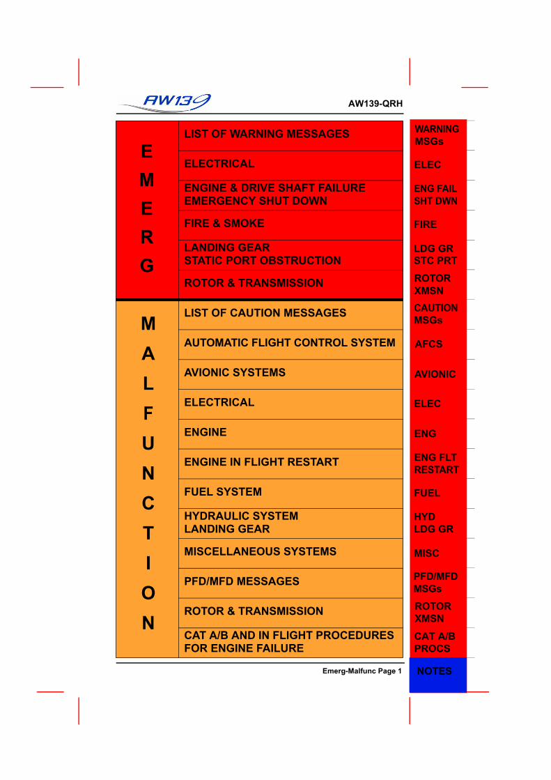
QRH GENERAL INFORMATIONCONTENT. The QRH consists of 4 sections which have been grouped intotwo parts. The first part combines Limitations, Normal Procedures and Per-formance Data. The second part contains Emergency/Malfunction Proce-dures. The two parts are mounted back-to-back to allow quick access toeither.
The various sections/systems are colour tabbed for ease and quickness oflocating the page required.
A Index of Content is included at the start of each of the two parts.
FLIGHT MANUAL. The QRH does not replace the RFM, however, all infor-mation contained in the QRH is based on the RFM. To operate the aircraftsafely and efficiently, the RFM must be read and thoroughly understood.
If any conflict should exist between this QRH and the Approved RFM theRFM shall take precedence.
QRH Limitations: The limitations have been copied from the RFM, how-ever any limitations that are covered by colour markings on the PFD/MFD(e.g engine limits, rotor limits) have not been included.
QRH Normal Procedures: The normal procedures have been copied fromthe RFM, CAT A and CAT B procedures have been included.
QRH Performance: The performance data includes only the Power Assur-ance Charts and, in tabulated data format, Hover Ceiling, Rate Of Climband Fuel Consumption.
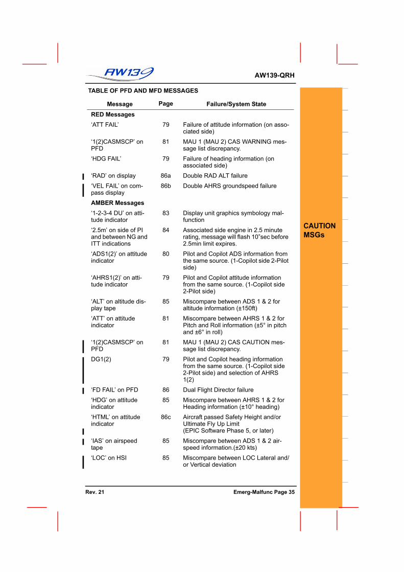
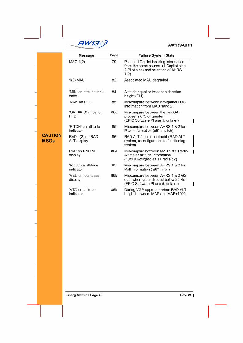
QRH Emergency and Malfunction Procedure: The procedures havebeen copied from the RFM and grouped into systems. The systems arethen highlighted with RED tabs for Emergency Procedures, AMBER tabs forMalfunction Procedures, which have been placed in alphabetical order.
Additionally a table of Warning and Caution messages and the appropriatepage number for the procedure is included at the start of each section(Emergency/Malfunction) to aid in rapid location of the correct page.
Optional Equipment: The QRH includes Limitations, Procedures andEmergency Malfunction Procedures on a small number of Optional Equi-pent Suppleents that may be applicable to the aircraft. The RFM must beconsulted for comprehensive information and applicability of the Limitations,Normal Procedures etc. for the Optional Equipment Supplements that areincluded on the aircraft.
TOC, RECof REVS
AW139-QRH Record of
Revisions
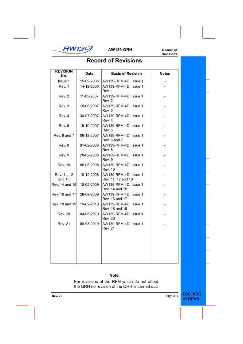
Record of Revisions
NoteFor revisions of the RFM which do not affectthe QRH no revision of the QRH is carried out.
Rev. 6 and 7 06-12-2007 AW139-RFM-4D Issue 1Rev. 6 and 7
-
Rev. 8 01-02-2008 AW139-RFM-4D Issue 1Rev. 8
-
Rev. 9 28-02-2008 AW139-RFM-4D Issue 1Rev. 9
-
Rev. 10 06-08-2008 AW139-RFM-4D Issue 1Rev. 10
-
Rev. 11, 12 and 13
18-12-2008 AW139-RFM-4D Issue 1Rev. 11, 12 and 13
-
Rev. 14 and 15 15-05-2009 AW139-RFM-4D Issue 1Rev. 14 and 15
-
Rev. 16 and 17 28-09-2009 AW139-RFM-4D Issue 1Rev. 16 and 17
-
Rev. 18 and 19 19-02-2010 AW139-RFM-4D Issue 1Rev. 18 and 19
-
Rev. 20 04-06-2010 AW139-RFM-4D Issue 1Rev. 20
-
Rev. 21 09-08-2010 AW139-RFM-4D Issue 1Rev. 21
-
UNMAINTAINED COPYFOR INFORMATION ONLY
Rev. 21 Page A-1 TOC, RECof REVS
UNMAINTAINED COPYFOR INFORMATION ONLY
AW139-QRH Record ofRevisions
Page A-2TOC, RECof REVS
AW139-QRH Record ofEffective Pages
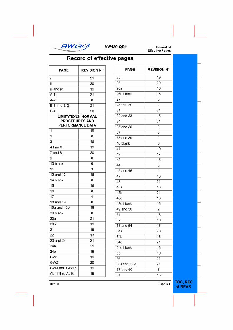
Record of effective pages
PAGE REVISION N°
i 21ii 20iii and iv 19A-1 21A-2 0B-1 thru B-3 21B-4 20
LIMITATIONS, NORMAL PROCEDURES AND
PERFORMANCE DATA1 192 03 164 thru 6 197 and 8 209 010 blank 011 312 and 13 1614 blank 015 1616 017 418 and 19 019a and 19b 1620 blank 020a 2120b 1921 1922 1323 and 24 2124a 2124b 15GW1 19GW2 20GW3 thru GW12 19ALT1 thru ALT6 19
25 1926 2026a 1626b blank 1627 028 thru 30 231 2132 and 33 1534 2135 and 36 237 838 and 39 240 blank 041 1942 1743 1544 045 and 46 447 1648 2148a 1648b 2148c 1648d blank 1649 and 50 251 1352 1053 and 54 1654a 2054b 1654c 2154d blank 1655 1056 2156a thru 56d 2157 thru 60 361 15
PAGE REVISION N°
UNMAINTAINED COPYFOR INFORMATION ONLY
Rev. 21 Page B-1 TOC, RECof REVS
F
AW139-QRH Record ofEffective Pages
TOC, RECof REVS
62 2063 1564 and 65 1966 1567 and 68 2069 and 70 071 2072 19
EMERGENCY AND MALFUNCTION PROCEDURES
1 and 2 03 194 thru 6 157 and 8 169 1910 2111 2012 213 014 315 1516 317 2118 and 19 1520 1621 1522 and 23 2024 1524a thru 24d (*) 1925 2126 2027 and 28 229 030 331 1532 2133 and 34 1535 and 36 21
PAGE REVISION N°
37 and 38 2039 and 40 1540a 1540b thru 40d 2141 1542 2143 2044 and 45 1546 047 2048 2149 750 2151 and 52 1552a 1552b blank 1553 2054 1655 2156 1657 058 and 59 1660 and 61 062 1563 and 64 2064a and 64b 2065 2066 267 068 269 1670 2171 1672 thru 74 275 076 2177 1578 20
PAGE REVISION N°
UNMAINTAINED COPYOR INFORMATION ONLY
Page B-2 Rev. 21
AW139-QRH Record ofEffective Pages
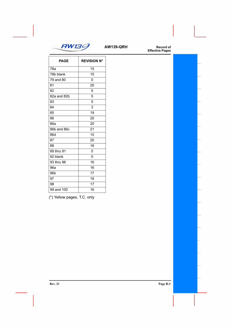
(*) Yellow pages, T.C. only
78a 1578b blank 1579 and 80 081 2082 582a and 82b 583 584 385 1986 2086a 2086b and 86c 2186d 1587 2088 1689 thru 91 092 blank 093 thru 96 1696a 1696b 1797 1698 1799 and 100 16
PAGE REVISION N°
UNMAINTAINED COPYFOR INFORMATION ONLY
Rev. 21 Page B-1Page B-3
F
AW139-QRH Record ofEffective Pages
UNMAINTAINED COPYOR INFORMATION ONLY
Page B-2 Rev. 20Page B-4
AW139-QRH
GENWT/CGSPD ALT
ENG FUEL
ABORTDRY MOTENGSTART
TAXI T-O
MISC
PRESTART
IN
FD/FMS
TEMP
LUB HYD
EXTN
CAT A/B
FLIGHT
OPER
POST LDSHT DN
HVR ROCFL CONS
CAPTSMSGS
SYSCHECKS
CHECKS
H-VCAT A/B
LANDAPPR
Hd PAVFLYAWAY
GENERAL, TYPE OF OPER, MIN CREW, WEIGHT, CG LIMITATIONS
SPEED, ALTITUDE, TEMP LIMITATIONS
H-V, CAT B/A LIMITATIONS
ENGINE, FUEL, LUBRICANTS, HYDRAULICS LIMITATIONS
MISCELLANEOUS LIMITATIONS
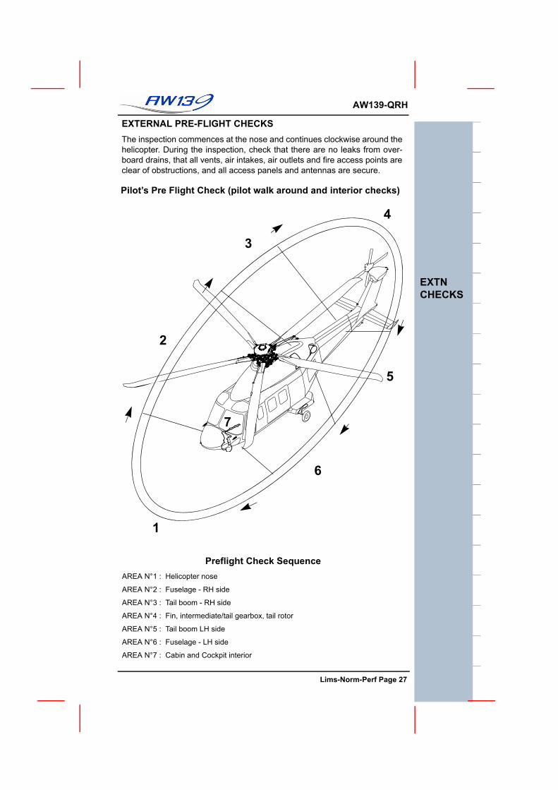
GENERAL, FLIGHT PLANNING, EXTERNAL CHECKS
PRE-START CHECKS
ABORTED ENGINE START DRY MOTORING PROCEDURE
ENGINE START PROCEDURE
SYSTEM CHECKS
TAXIING, PRE-TAKE OFF, TAKE OFF
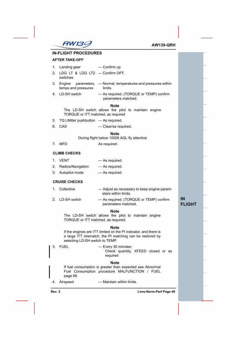
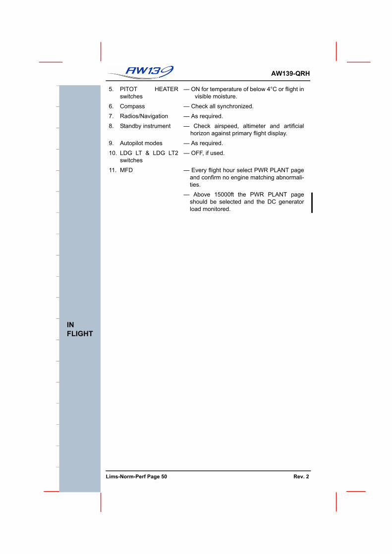
IN FLIGHT PROCEDURES
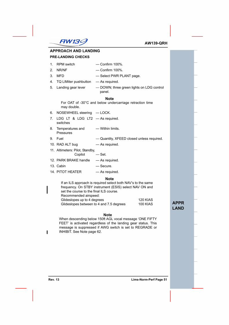
APPROACH, LANDING CAT B/A
POST LANDING & SHUTDOWN
FLIGHT MANAGEMENT SYSTEM OPER-ATIONADVISORY CAPTIONS, PDF MESSAGESDENSITY ALTITUDE, POWER ASSUR,CAT B & A DISTANCE CHARTSHOVER CEILING, ROC, FUEL CONSUMPTION
LI
MITS
GENERAL, TYPE OF OPER, MIN CREW, WEIGHT, CG LIMITATIONS
SPEED, ALTITUDE, TEMP LIMITATIONS
H-V, CAT A/B LIMITATIONS
ENGINE, FUEL, LUBRICANTS, HYDRAULICS LIMITATIONSMISCELLANEOUS LIMITATIONS(GW EXT, ALT EXT if applicable)GENERAL, FLIGHT PLANNING, EXTERNAL CHECKS
PRE-START CHECKS
ABORTED ENGINE START DRY MOTORING PROCEDURE
ENGINE START PROCEDURE
SYSTEM CHECKS
TAXIING, PRE-TAKE OFF, TAKE-OFF CAT A/B
IN FLIGHT PROCEDURES
APPROACH, LANDING CAT A/B
POST LANDING & SHUTDOWN
FLIGHT DIRECTOR AND FLIGHT MANAGEMENT SYSTEM OPERATIONADVISORY CAPTIONS, PDF MESSAGESDENSITY ALTITUDE, POWER ASSURFLYAWAY HEIGHT LOSSHOVER CEILING, ROC, FUEL CONSUMPTION
N
O
R
M
A
L
PROCEDURES
PE
RF
LI
MITS
UNMAINTAINED COPYFOR INFORMATION ONLY
Rev. 19 Lims-Norm-Perf Page 1 TOC, RECof REVS
F
AW139-QRH
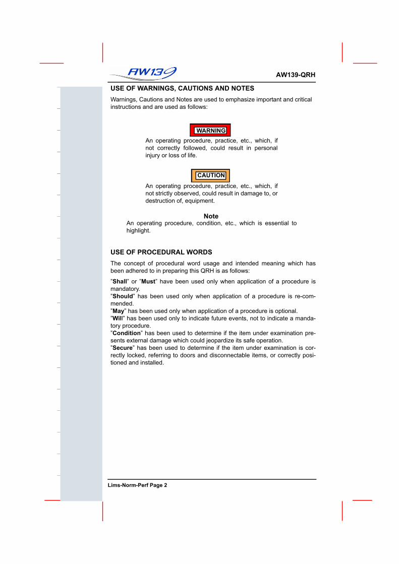
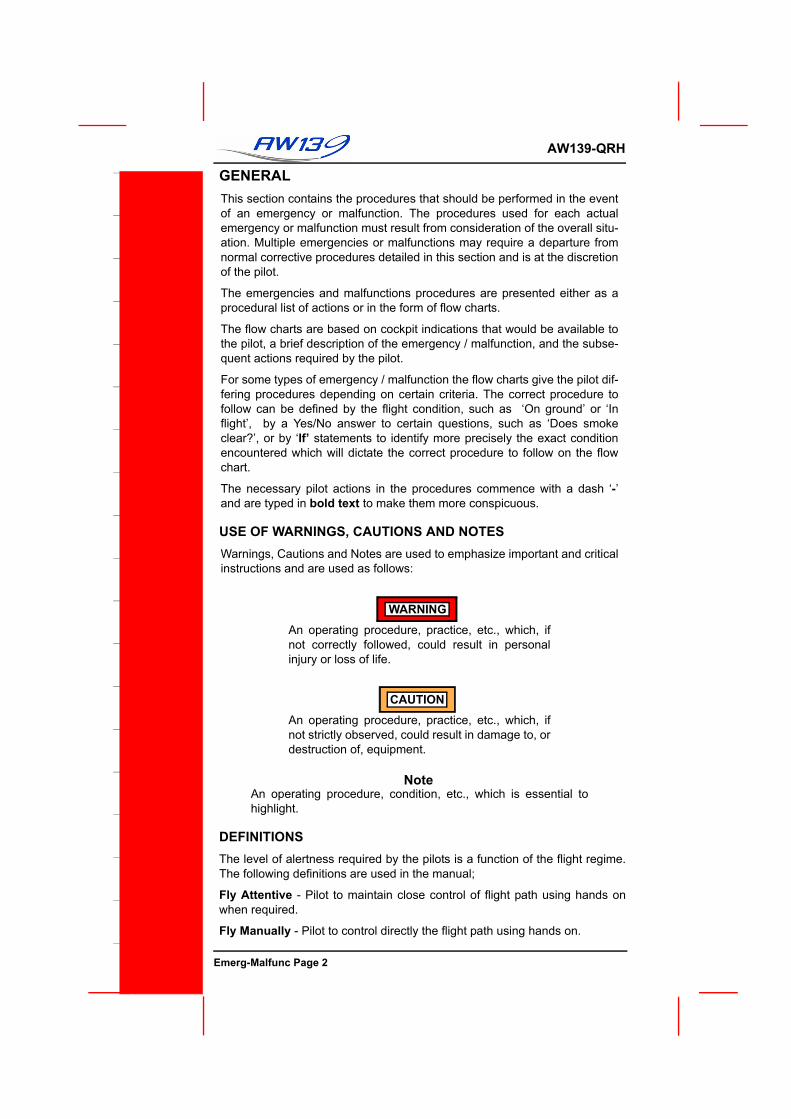
USE OF WARNINGS, CAUTIONS AND NOTESWarnings, Cautions and Notes are used to emphasize important and criticalinstructions and are used as follows:
WARNINGAn operating procedure, practice, etc., which, ifnot correctly followed, could result in personalinjury or loss of life.
CAUTION
An operating procedure, practice, etc., which, ifnot strictly observed, could result in damage to, ordestruction of, equipment.
NoteAn operating procedure, condition, etc., which is essential tohighlight.
USE OF PROCEDURAL WORDSThe concept of procedural word usage and intended meaning which hasbeen adhered to in preparing this QRH is as follows:
”Shall” or ”Must” have been used only when application of a procedure ismandatory.”Should” has been used only when application of a procedure is re-com-mended.”May” has been used only when application of a procedure is optional.”Will” has been used only to indicate future events, not to indicate a manda-tory procedure.”Condition” has been used to determine if the item under examination pre-sents external damage which could jeopardize its safe operation.”Secure” has been used to determine if the item under examination is cor-rectly locked, referring to doors and disconnectable items, or correctly posi-tioned and installed.
UNMAINTAINED COPYOR INFORMATION ONLY
Lims-Norm-Perf Page 2
AW139-QRH
LIMITATIONSGENERAL....................................................................................... 7TYPES OF OPERATION................................................................. 7MINIMUM FLIGHT CREW .............................................................. 7NUMBER OF OCCUPANTS ........................................................... 7WEIGHT AND CENTER OF GRAVITY LIMITATIONS................... 7AIRSPEED LIMITATIONS .............................................................. 11GROUND SPEED LIMITATIONS ................................................... 11WIND SPEED LIMITATIONS FOR ROTOR STARTING & STOPPING ............................................................... 12ALTITUDE LIMITATIONS ............................................................... 12AMBIENT AIR TEMPERATURE LIMITATIONS (OAT) .................. 12MANOEUVRING LIMITATIONS ..................................................... 12ICING LIMITATIONS....................................................................... 12AUTOROTATION LIMITATIONS .................................................... 12SLOPE LIMITATIONS .................................................................... 13ALTITUDE AND TEMPERATURE LIMITATIONS CHART ............ 13HEIGHT- VELOCITY LIMITATIONS ............................................... 15CAT A MISCELLANEOUS LIMITATIONS...................................... 15HEIGHT - VELOCITY DIAGRAM.................................................... 16CATEGORY B OPERATION LIMITATIONS................................... 17CATEGORY A OPERATION LIMITATIONS................................... 18ENGINE AND TRANSMISSION DIGITAL LIMITATIONS ............ 20aENGINE LIMITATIONS................................................................... 21
NORMAL PROCEDURESGENERAL ...................................................................................... 25FLIGHT PLANNING ....................................................................... 25
CAT B WEIGHT AND H-V DETERMINATION .......................... 25CATEGORY A PROCEDURES................................................. 25CATEGORY A TAKE OFF......................................................... 25VERTICAL PROCEDURE ......................................................... 25SHORT FIELD PROCEDURE................................................... 25BACK UP PROCEDURE........................................................... 25CLEAR AREA PROCEDURE.................................................... 25CONFINED AREA PROCEDURE ............................................. 26OFFSHORE HELIDECK PROCEDURE.................................... 26CATEGORY A LANDING .......................................................... 26HELIPORT/HELIDECK PROCEDURE...................................... 26CLEAR AREA PROCEDURE.................................................... 26CONFINED AREA PROCEDURE ............................................. 26OFFSHORE HELIDECK PROCEDURE................................... 26a
PRE TAKE-OFF CHECKS.............................................................. 43TAKE-OFF PROCEDURES ............................................................ 44
TAKE-OFF CATEGORY B PROCEDURE................................. 44CATEGORY A TAKE-OFF GENERAL........................................45CATEGORY A TAKE-OFF VERTICAL, SHORT FIELD AND BACK UP PROCEDURE................................................... 45CATEGORY A TAKE-OFF CLEAR AREA PROCEDURE ......... 46CATEGORY A TAKE-OFF CONFINED AREA PROCEDURE ...47CATEGORY A TAKE-OFF OFFSHORE HELIDECK PROCEDURE ............................................................................48a
SLOPING GROUND OPERATION................................................ 48cTAKE OFF PROCEDURE......................................................... 48c
APPROACH AND LANDING.......................................................... 51PRE-LANDING CHECKS........................................................... 51
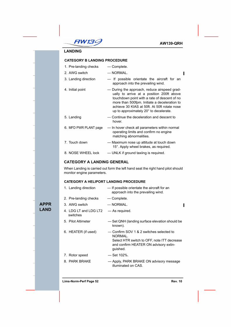
LANDING ........................................................................................ 52CATEGORY B LANDING PROCEDURE................................... 52CATEGORY A LANDING GENERAL..........................................52CATEGORY A HELIPORT LANDING PROCEDURE................ 52CATEGORY A CLEAR AREA LANDING PROCEDURE........... 53CATEGORY A CONFINED AREA LANDING PROCEDURE .... 53CATEGORY A OFFSHORE HELIDECK LANDING PROCEDURE ........................................................................... 54a
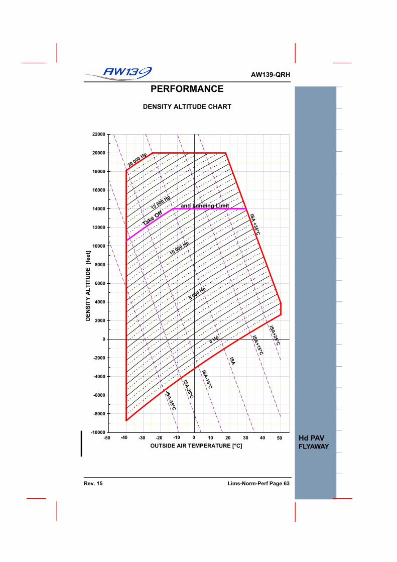
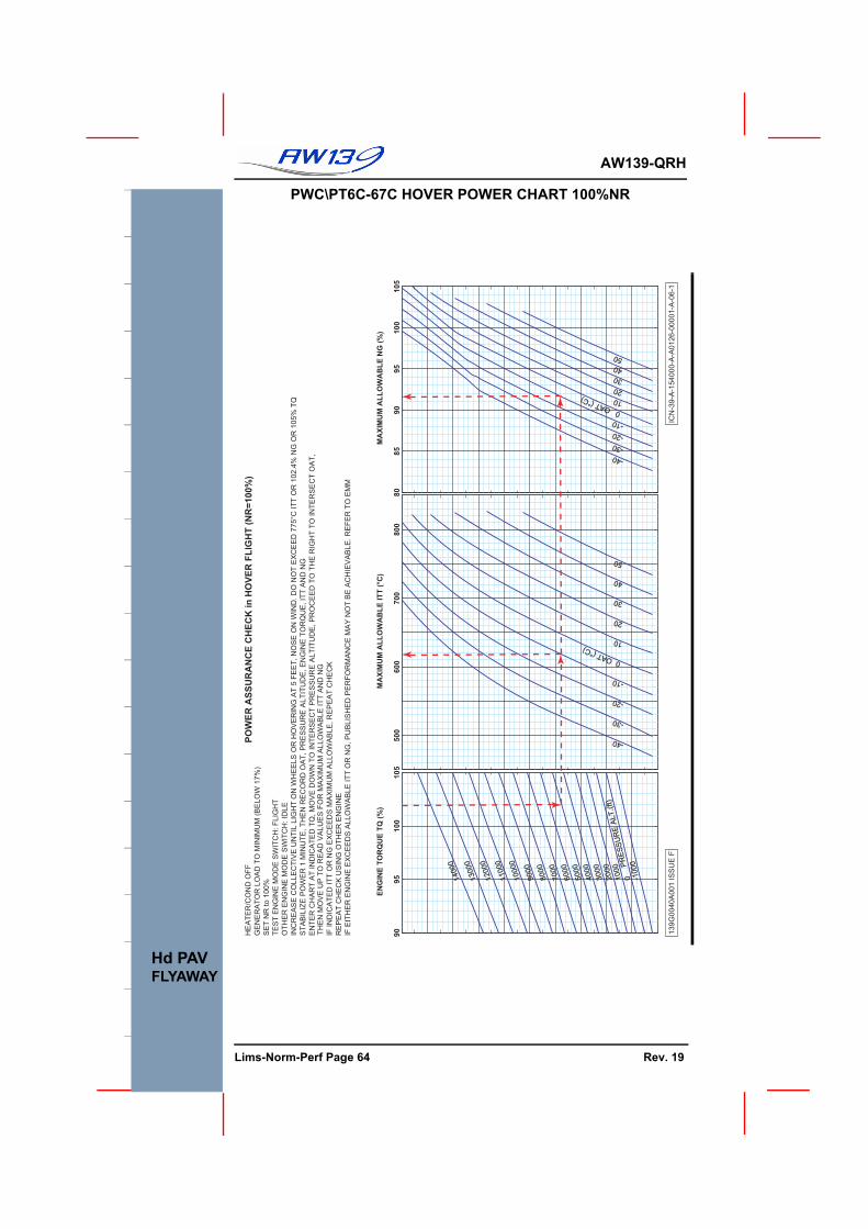
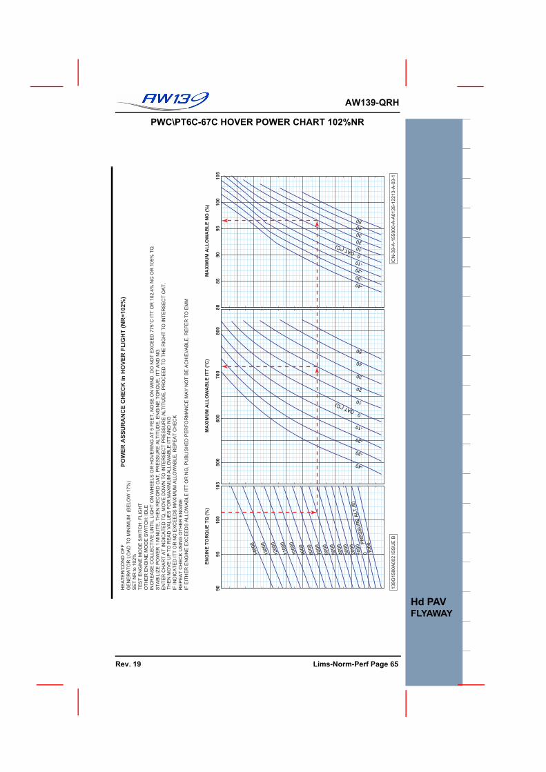
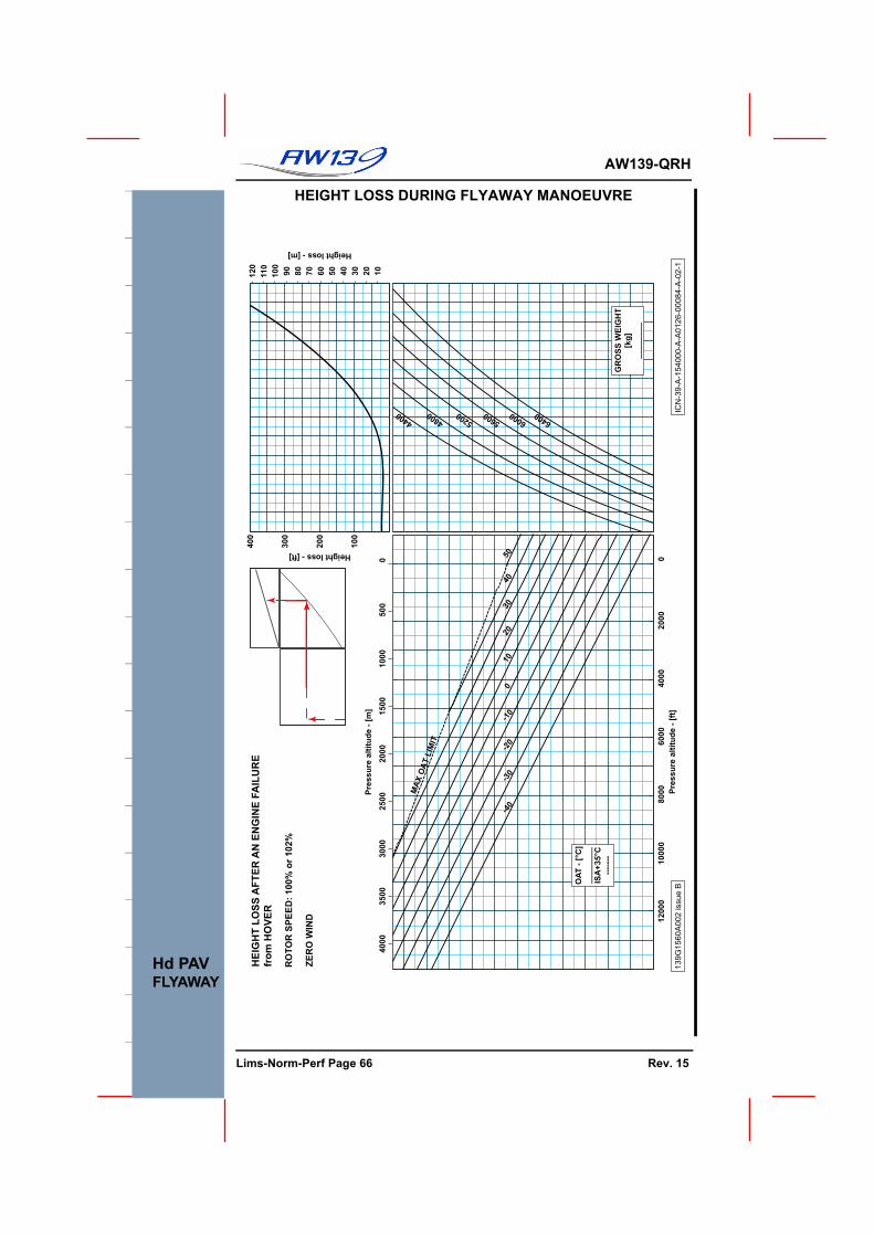
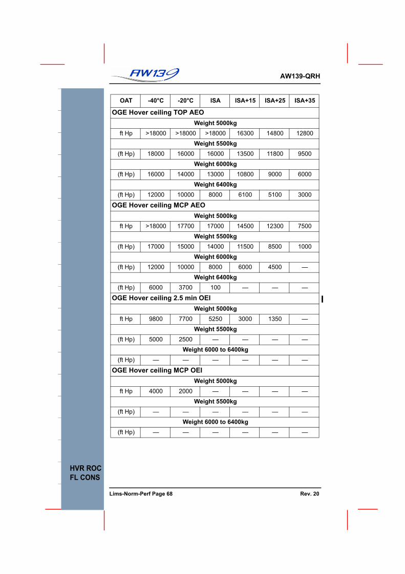
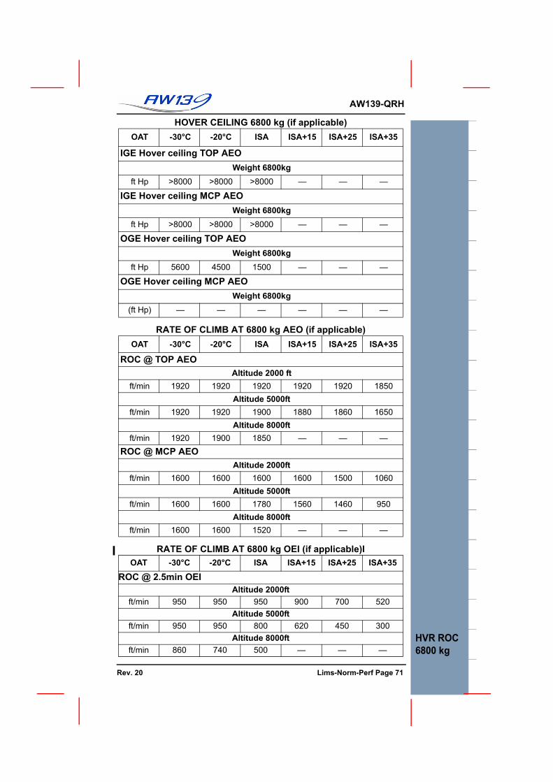
PERFORMANCEDENSITY ALTITUDE CHART........................................................ 63PWC\PT6C-67C HOVER POWER CHART 100%NR .................... 64PWC\PT6C-67C HOVER POWER CHART 102%NR .................... 65HEIGHT LOSS DURING FLYAWAY MONOEUVRE .................... 66HOVER CEILING .......................................................................... 67RATE OF CLIMB AT 6400 kg AEO............................................... 69RATE OF CLIMB AT 6400 kg OEI ................................................ 69FUEL CONSUMPTION AT 6400kg ............................................... 70HOVER CEILING 6800 kg (if applicable) ..................................... 71RATE OF CLIMB AT 6800 kg AEO (if applicable)....................... 71RATE OF CLIMB AT 6800 kg OEI (if applicable) ........................ 71FUEL CONSUMPTION AT 6800 kg (if applicable) ...................... 72
UNMAINTAINED COPYOR INFORMATION ONLY
Lims-Norm-Perf Page 6 Rev. 19
AW139-QRH
GENWT/CG
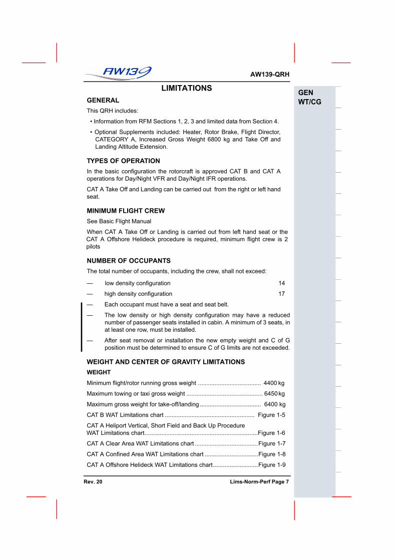
LIMITATIONSGENERALThis QRH includes:
• Information from RFM Sections 1, 2, 3 and limited data from Section 4.
• Optional Supplements included: Heater, Rotor Brake, Flight Director,CATEGORY A, Increased Gross Weight 6800 kg and Take Off andLanding Altitude Extension.
TYPES OF OPERATIONIn the basic configuration the rotorcraft is approved CAT B and CAT Aoperations for Day/Night VFR and Day/Night IFR operations.
CAT A Take Off and Landing can be carried out from the right or left handseat.
MINIMUM FLIGHT CREWSee Basic Flight Manual
When CAT A Take Off or Landing is carried out from left hand seat or theCAT A Offshore Helideck procedure is required, minimum flight crew is 2pilots
NUMBER OF OCCUPANTSThe total number of occupants, including the crew, shall not exceed:
— low density configuration 14
— high density configuration 17
— Each occupant must have a seat and seat belt.
— The low density or high density configuration may have a reducednumber of passenger seats installed in cabin. A minimum of 3 seats, inat least one row, must be installed.
— After seat removal or installation the new empty weight and C of Gposition must be determined to ensure C of G limits are not exceeded.
WEIGHT AND CENTER OF GRAVITY LIMITATIONSWEIGHT
Minimum flight/rotor running gross weight ...................................... 4400 kg
Maximum towing or taxi gross weight .............................................. 6450 kg
Maximum gross weight for take-off/landing..................................... 6400 kg
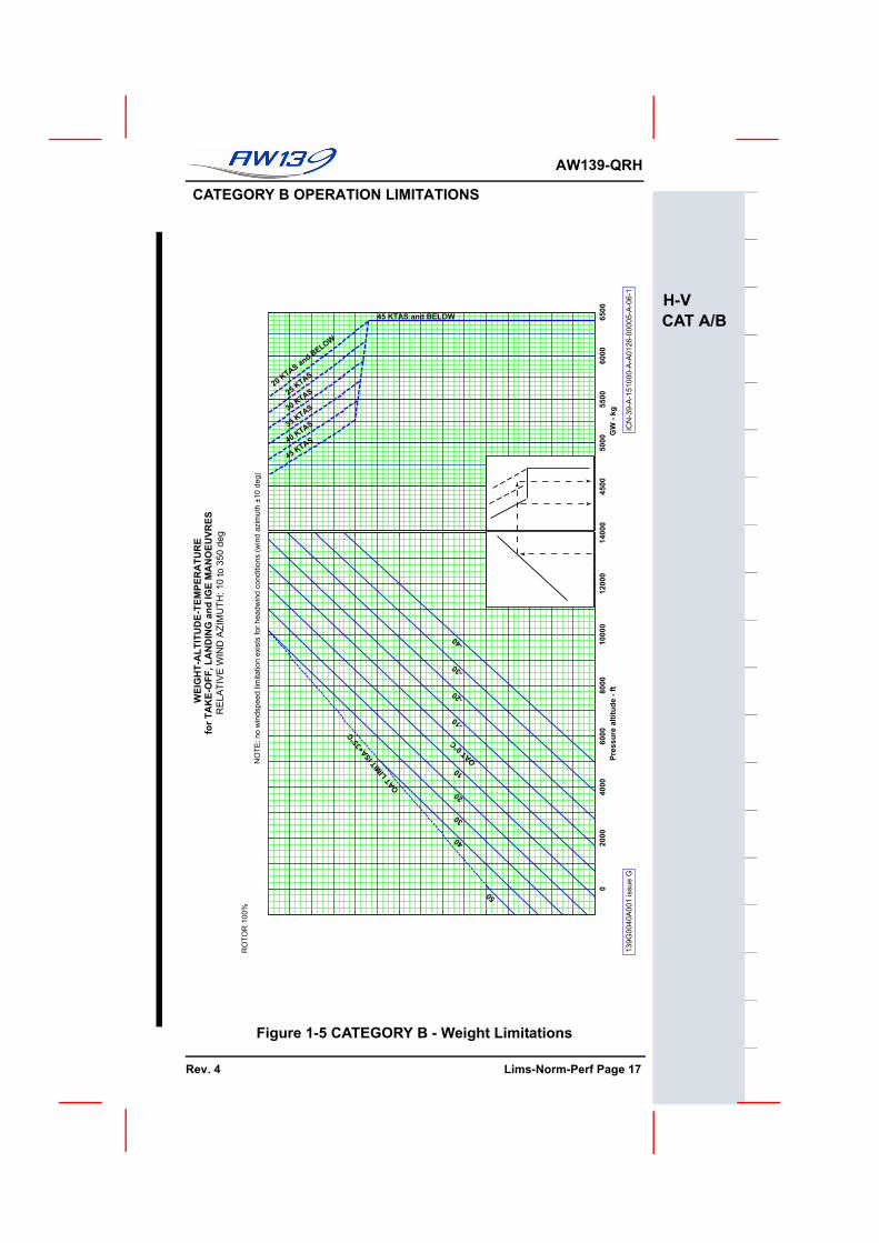
CAT B WAT Limitations chart ...................................................... Figure 1-5
CAT A Heliport Vertical, Short Field and Back Up Procedure WAT Limitations chart....................................................................Figure 1-6
CAT A Clear Area WAT Limitations chart ......................................Figure 1-7
CAT A Confined Area WAT Limitations chart ................................Figure 1-8
CAT A Offshore Helideck WAT Limitations chart...........................Figure 1-9
UNMAINTAINED COPYFOR INFORMATION ONLY
Rev. 20 Lims-Norm-Perf Page 7
F
AW139-QRH
GENWT/CG
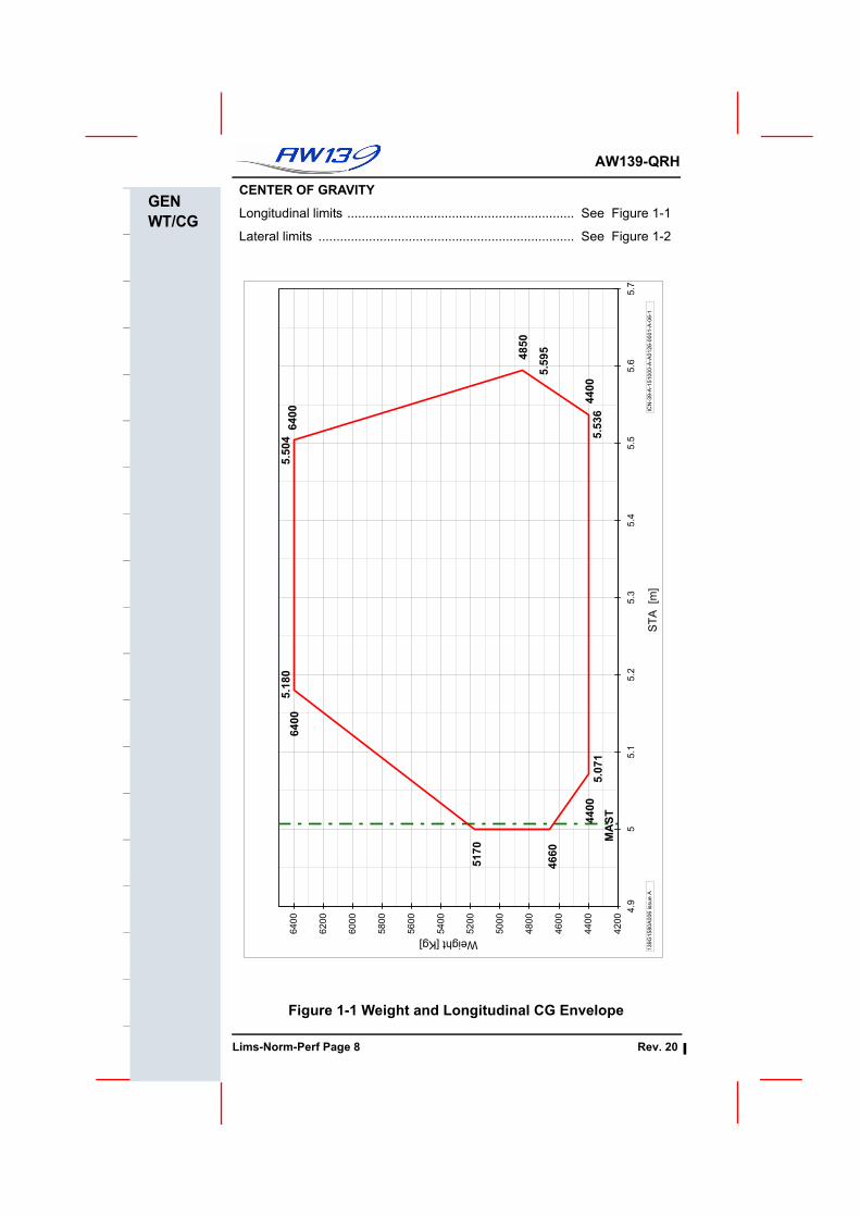
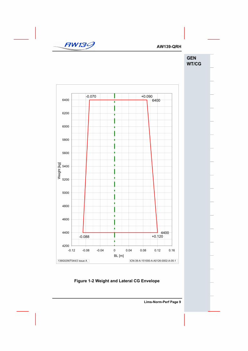
CENTER OF GRAVITY
Longitudinal limits ............................................................... See Figure 1-1
Lateral limits ....................................................................... See Figure 1-2
Figure 1-1 Weight and Longitudinal CG Envelope
MA
ST
5.5
04
5.1
80
6400
4400
5.0
71
5.5
36
4400
5170
5.5
95
4850
4660
6400
4200
4400
4600
4800
5000
5200
5400
5600
5800
6000
6200
6400
4.9
55.1
5.2
5.3
5.4
5.5
5.6
5.7
ST
A [m
]
Weight [Kg]
ICN
-39
-A-1
51
00
0-A
-A0
12
6-0
00
1-A
-06
-11
39
G1
58
0A
00
6 issu
e A
UNMAINTAINED COPYOR INFORMATION ONLY
Lims-Norm-Perf Page 8 Rev. 20
AW139-QRH
GENWT/CG
Figure 1-2 Weight and Lateral CG Envelope
-0.088
6400
+0.090-0.070
+0.120
4400
4200
4400
4600
4800
5000
5200
5400
5600
5800
6000
6200
6400
-0.12 -0.08 -0.04 0 0.04 0.08 0.12 0.16
BL [m]
Weig
ht [k
g]
139G0290T044/2 issue A ICN-39-A-151000-A-A0126-0002-A-05-1
UNMAINTAINED COPYFOR INFORMATION ONLY
Lims-Norm-Perf Page 9
F
AW139-QRH
This Page Left Blank Intentionally
UNMAINTAINED COPYOR INFORMATION ONLY
Lims-Norm-Perf Page 10
AW139-QRH
SPD ALTTEMP
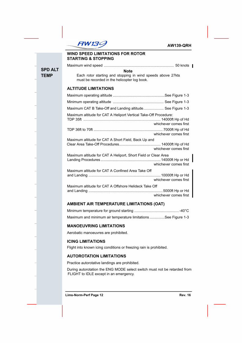
AIRSPEED LIMITATIONSMaximum airspeed with Take-Off Power .......................................... 90 KIAS
Maximum airspeed with NR at 102% ............................................... 90 KIAS
Maximum airspeed in sideward or rearward flight ........................ Figure 1-5
Maximum allowable tailwind and crosswind ................................. Figure 1-5
Maximum airspeed for landing gear VLO or VLE.........................150 KIAS orVne if less
Minimum airspeed for flight under IFR (Vmini) ................................ 50 KIAS
Maximum airspeed for IFR approach ............................................. 150 KIAS
Maximum airspeed for climb with one AP failed............................. 100 KIAS
Maximum rate of climb with one AP failed...................................... 1000 fpm
Maximum airspeed with one AP failed ........................................... 140 KIAS
Maximum airspeed for operation of windscreen wipers ................. 140 KIAS
Minimum airspeed in autorotation .................................................... 40 KIAS
CAT A Take-Off & Balked Landing Safety Speed (VTOSS/VBLSS):Vertical, Short Field and Back Up Procedures............................. 40 KIAS
Clear Area Procedure .................................................................. 50 KIAS
Best Rate Of Climb speed (VY) ............................Below 10000ft Hp 80 KIASAbove 10000ft Hp 70 KIAS
Maximum airspeed with right cabin door locked open....................100 KIAS
Maximum airspeed with left or both cabin doors locked open.......... 80 KIAS
Maximum airspeed for opening/closing cabin doors ........................ 80 KIAS
GROUND SPEED LIMITATIONSON PAVED SURFACES
Maximum taxi speed ....................................................................... 40 knots(above 20 knots nose wheel must be locked fore and aft)
Maximum for emergency landing speed(nose wheel locked in fore and aft position) ................................... 60 knots
Maximum towing speed .................................................... 37 km/hr(23mph)
Maximum GS with PARK BRAKE ON ................................................... 5 kts
ON GRASS SURFACES
Maximum taxi speed (nose wheel locked fore and aft) .................. 20 knots(above 10 knots nose wheel must be locked fore and aft)
Maximum speed for emergency landing(nose wheel locked fore and aft) .................................................... 40 knots
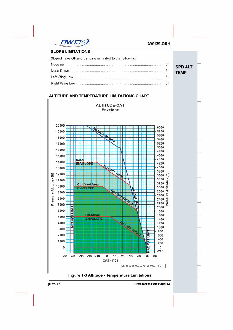
Minimum operating altitude .................................................. See Figure 1-3
Maximum CAT B Take-Off and Landing altitude.................... See Figure 1-3
Maximum altitude for CAT A Heliport Vertical Take-Off Procedure:TDP 35ft ............................................................................ 14000ft Hp of Hd
whichever comes firstTDP 36ft to 70ft .................................................................... 7000ft Hp of Hd
whichever comes firstMaximum altitude for CAT A Short Field, Back Up and Clear Area Take-Off Procedures......................................... 14000ft Hp of Hd
whichever comes first
Maximum altitude for CAT A Heliport, Short Field or Clear Area Landing Procedures ........................................................... 14000ft Hp or Hd
whichever comes first
Maximum altitude for CAT A Confined Area Take Offand Landing ....................................................................... 10000ft Hp or Hd
whichever comes first
Maximum altitude for CAT A Offshore Helideck Take Offand Landing ......................................................................... 5000ft Hp or Hd
whichever comes first
AMBIENT AIR TEMPERATURE LIMITATIONS (OAT)Minimum temperature for ground starting ............................................ -40°C
Maximum and minimum air temperature limitations ...............See Figure 1-3
MANOEUVRING LIMITATIONSAerobatic manoeuvres are prohibited.
ICING LIMITATIONSFlight into known icing conditions or freezing rain is prohibited.
AUTOROTATION LIMITATIONSPractice autorotative landings are prohibited.
During autorotation the ENG MODE select switch must not be retarded fromFLIGHT to IDLE except in an emergency.
UNMAINTAINED COPYOR INFORMATION ONLY
Lims-Norm-Perf Page 12 Rev. 16
AW139-QRH
SPD ALTTEMP
SLOPE LIMITATIONSSloped Take Off and Landing is limited to the following:
Nose up ...................................................................................................... 5°
Nose Down................................................................................................. 5°
Left Wing Low............................................................................................. 5°
Right Wing Low .......................................................................................... 5°
ALTITUDE AND TEMPERATURE LIMITATIONS CHART
Figure 1-3 Altitude - Temperature Limitations
ALTITUDE-OATEnvelope
ICN-39-A-151000-A-A0126-00004-B-01-1
-200
0
200
400
600
800
1000
1200
1400
1600
1800
2000
2200
2400
2600
2800
3000
3200
3400
3600
3800
4000
4200
4400
4600
4800
5000
5200
5400
5600
5800
6000
Pre
ssu
re A
ltit
ud
e -
[m
]
-50 -40 -30 -20 -10 0 10 20 30 40 50 60
0
1000
2000
3000
4000
5000
6000
7000
8000
9000
10000
11000
12000
13000
14000
15000
16000
17000
18000
19000
20000
OAT - [°C]
Pre
ssu
re A
ltit
ud
e -
[ft
]
MIN
OA
T L
IMIT
MA
X O
AT
LIM
IT
Hd
LIM
IT 20000 ft
Hd LIMIT
20000 ft
Hd LIMIT 14000 ft
Cat.A
ENVELOPE
Hd LIMIT 10000 ft
Confined Area
ENVELOPE
Hd LIMIT 5000 ft
Off-Shore
ENVELOPE
UNMAINTAINED COPYFOR INFORMATION ONLY
Rev. 16 Lims-Norm-Perf Page 13
F
AW139-QRH
This Page Left Blank Intentionally
UNMAINTAINED COPYOR INFORMATION ONLY
Lims-Norm-Perf Page 14
AW139-QRH
H-VCAT A/B
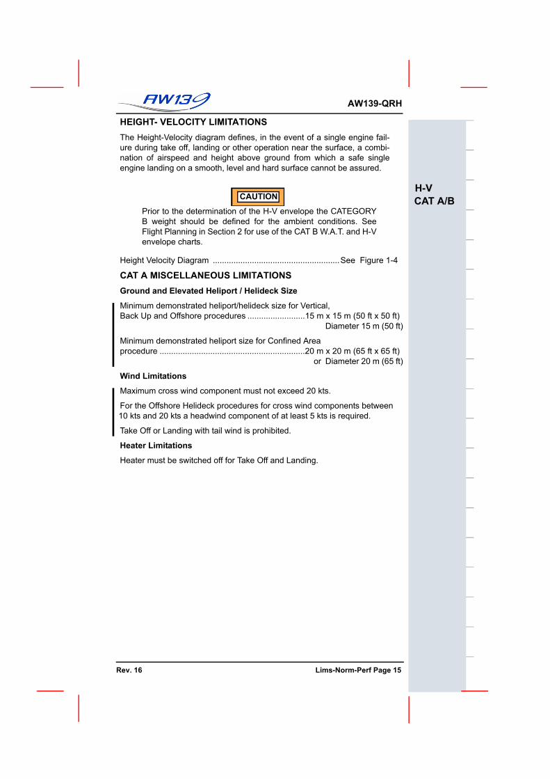
HEIGHT- VELOCITY LIMITATIONSThe Height-Velocity diagram defines, in the event of a single engine fail-ure during take off, landing or other operation near the surface, a combi-nation of airspeed and height above ground from which a safe singleengine landing on a smooth, level and hard surface cannot be assured.
CAUTION
Prior to the determination of the H-V envelope the CATEGORYB weight should be defined for the ambient conditions. SeeFlight Planning in Section 2 for use of the CAT B W.A.T. and H-Venvelope charts.
CAT A MISCELLANEOUS LIMITATIONSGround and Elevated Heliport / Helideck Size
Minimum demonstrated heliport/helideck size for Vertical,Back Up and Offshore procedures .........................15 m x 15 m (50 ft x 50 ft) Diameter 15 m (50 ft)
Minimum demonstrated heliport size for Confined Areaprocedure ...............................................................20 m x 20 m (65 ft x 65 ft) or Diameter 20 m (65 ft)
Wind Limitations
Maximum cross wind component must not exceed 20 kts.
For the Offshore Helideck procedures for cross wind components between 10 kts and 20 kts a headwind component of at least 5 kts is required.
Take Off or Landing with tail wind is prohibited.
Heater Limitations
Heater must be switched off for Take Off and Landing.
UNMAINTAINED COPYFOR INFORMATION ONLY
Rev. 16 Lims-Norm-Perf Page 15
F
AW139-QRH
H-VCAT A/B
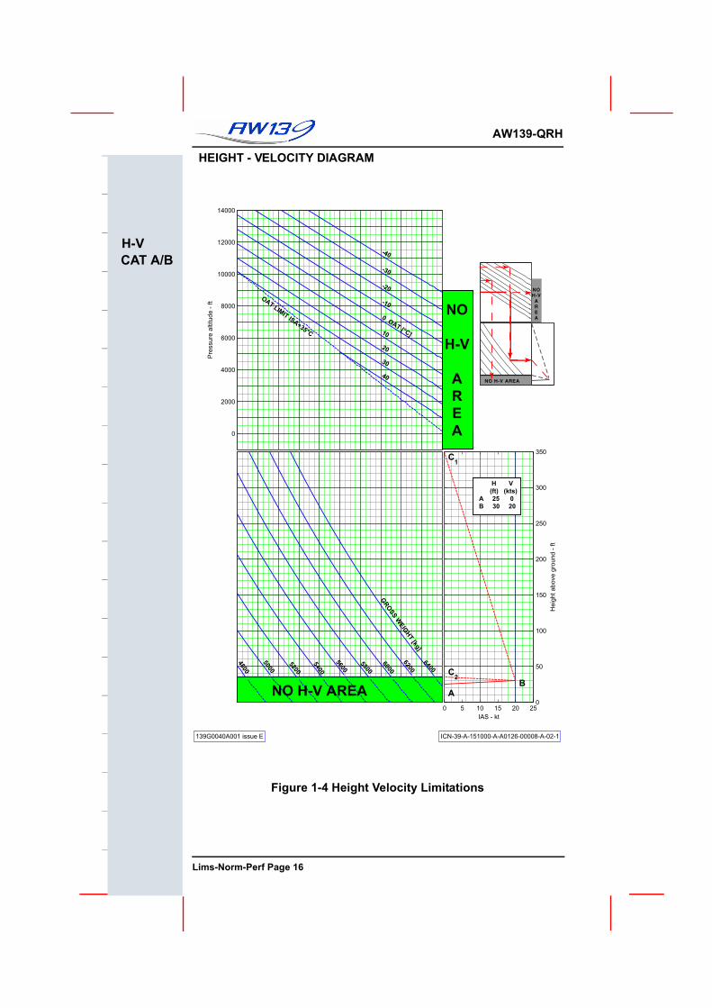
HEIGHT - VELOCITY DIAGRAM
Figure 1-4 Height Velocity Limitations
139G0040A001 issue E ICN-39-A-151000-A-A0126-00008-A-02-1
0
2000
4000
6000
8000
10000
12000
14000P
ressu
rea
ltitu
de
-ft
OA
TLIM
ITIS
A+35°C
-40
-30
-20
-10
0O
AT
[°C]10
20
30
40
4800
5000
5200
5400
5600
5800
6000
6200
6400
NO H-V AREA
0 5 10 15 20 25
0
50
100
150
200
250
300
350
IAS - kt
He
igh
ta
bo
ve
gro
un
d-
ft
A
B
C2
C1
GR
OSS
WEIG
HT
[kg]
NO H-V AREA
NOH-V
AREA
NO
H-V
A
R
E
A
H V
(ft) (kts)
A 25 0
B 30 20
UNMAINTAINED COPYOR INFORMATION ONLY
Lims-Norm-Perf Page 16
AW139-QRH
H-VCAT A/B
CATEGORY B OPERATION LIMITATIONS
Figure 1-5 CATEGORY B - Weight Limitations
WE
IGH
T-A
LT
ITU
DE
-TE
MP
ER
AT
UR
E
RO
TO
R1
00
%
13
9G
00
40
A0
01
issu
eG
ICN
-39
-A-1
51
00
0-A
-A0
12
6-0
00
05
-A-0
6-1
02
00
04
00
06
00
08
00
01
00
00
12
00
01
40
00
OAT
LIM
ITIS
A+35°C
Pre
ss
ure
alt
itu
de
-ft
-40
-30
-20
-10
OAT
0°C
10
20
30
40
50
45
00
50
00
55
00
60
00
65
00
45 KTAS and BELOW
45K
TAS40
KTA
S35K
TA
S30K
TA
S25K
TA
S
20K
TA
San
dB
ELO
W
GW
-k
g
for
TA
KE
-OF
F,L
AN
DIN
Gan
dIG
EM
AN
OE
UV
RE
S
RE
LA
TIV
EW
IND
AZ
IMU
TH
:10
to350
deg
NO
TE
:n
ow
ind
sp
ee
dlim
ita
tio
ne
xis
tsfo
rh
ea
dw
ind
co
nd
itio
ns
(win
da
zim
uth
±1
0d
eg
)
UNMAINTAINED COPYFOR INFORMATION ONLY
Rev. 4 Lims-Norm-Perf Page 17
F
AW139-QRH
H-VCAT A/B
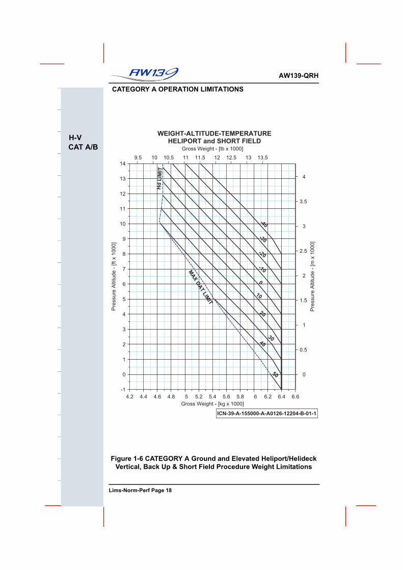
CATEGORY A OPERATION LIMITATIONS
Figure 1-6 CATEGORY A Ground and Elevated Heliport/Helideck Vertical, Back Up & Short Field Procedure Weight Limitations
WEIGHT-ALTITUDE-TEMPERATUREHELIPORT and SHORT FIELD
9.5 10 10.5 11 11.5 12 12.5 13 13.5
0
0.5
1
1.5
2
2.5
3
3.5
4
Pre
ssur
e A
ltitu
de -
[m x
100
0]
Gross Weight - [lb x 1000]
4.2 4.4 4.6 4.8 5 5.2 5.4 5.6 5.8 6 6.2 6.4 6.6-1
0
1
2
3
4
5
6
7
8
9
10
11
12
13
14
Pre
ssur
e A
ltitu
de -
[ft x
100
0]
Gross Weight - [kg x 1000]
-40
-30
-20
-10
0
10
20
3040
50
MAX OAT LIM
IT
Hd
LIM
IT
ICN-39-A-155000-A-A0126-12204-B-01-1
UNMAINTAINED COPYOR INFORMATION ONLY
Lims-Norm-Perf Page 18
AW139-QRH
H-VCAT A/B
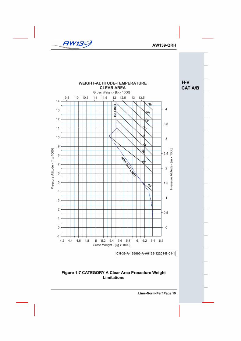
Figure 1-7 CATEGORY A Clear Area Procedure Weight Limitations
WEIGHT-ALTITUDE-TEMPERATURECLEAR AREA
ICN-39-A-155000-A-A0126-12201-B-01-1
9.5 10 10.5 11 11.5 12 12.5 13 13.5
0
0.5
1
1.5
2
2.5
3
3.5
4
Pre
ssur
e A
ltitu
de -
[m x
100
0]
Gross Weight - [lb x 1000]
4.2 4.4 4.6 4.8 5 5.2 5.4 5.6 5.8 6 6.2 6.4 6.6-1
0
1
2
3
4
5
6
7
8
9
10
11
12
13
14
Pre
ssur
e A
ltitu
de -
[ft x
100
0]
Gross Weight - [kg x 1000]
-40
-30
-20
-100
10
20
30
40
MAX OAT LIMIT
Hd
LIM
IT
UNMAINTAINED COPYFOR INFORMATION ONLY
Lims-Norm-Perf Page 19
F
AW139-QRH
H-VCAT A/B
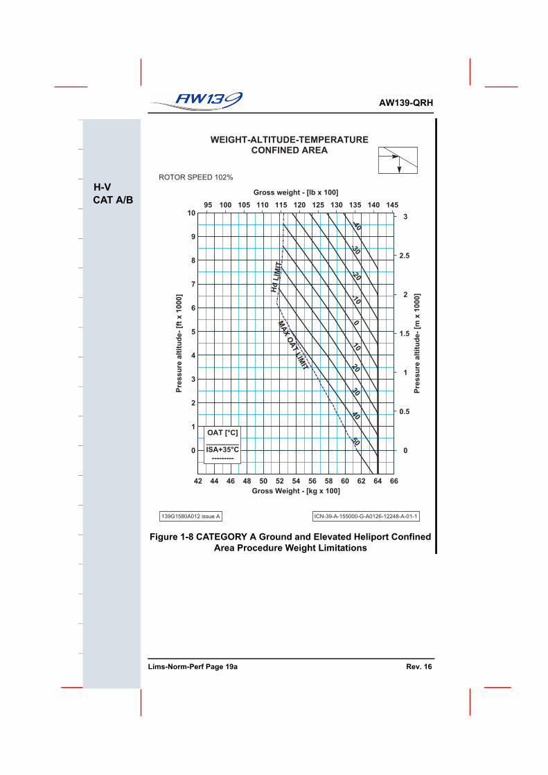
Figure 1-8 CATEGORY A Ground and Elevated Heliport Confined Area Procedure Weight Limitations
WEIGHT-ALTITUDE-TEMPERATURECONFINED AREA
ROTOR SPEED 102%
139G1580A012 issue A ICN-39-A-155000-G-A0126-12248-A-01-1
95 100 105 110 115 120 125 130 135 140 145
0
0.5
1
1.5
2
2.5
3
Gross weight - [lb x 100]
Pre
ss
ure
alt
itu
de
- [m
x 1
00
0]
42 44 46 48 50 52 54 56 58 60 62 64 66
0
1
2
3
4
5
6
7
8
9
10
Gross Weight - [kg x 100]
Pre
ss
ure
alt
itu
de
- [f
t x
10
00
]
OAT [°C]________ISA+35°C
---------
-40-30
-20-10
010
2030
4050
MA
X O
AT L
IMIT
Hd
LIM
IT
UNMAINTAINED COPYOR INFORMATION ONLY
Lims-Norm-Perf Page 19a Rev. 16
AW139-QRH
H-VCAT A/B
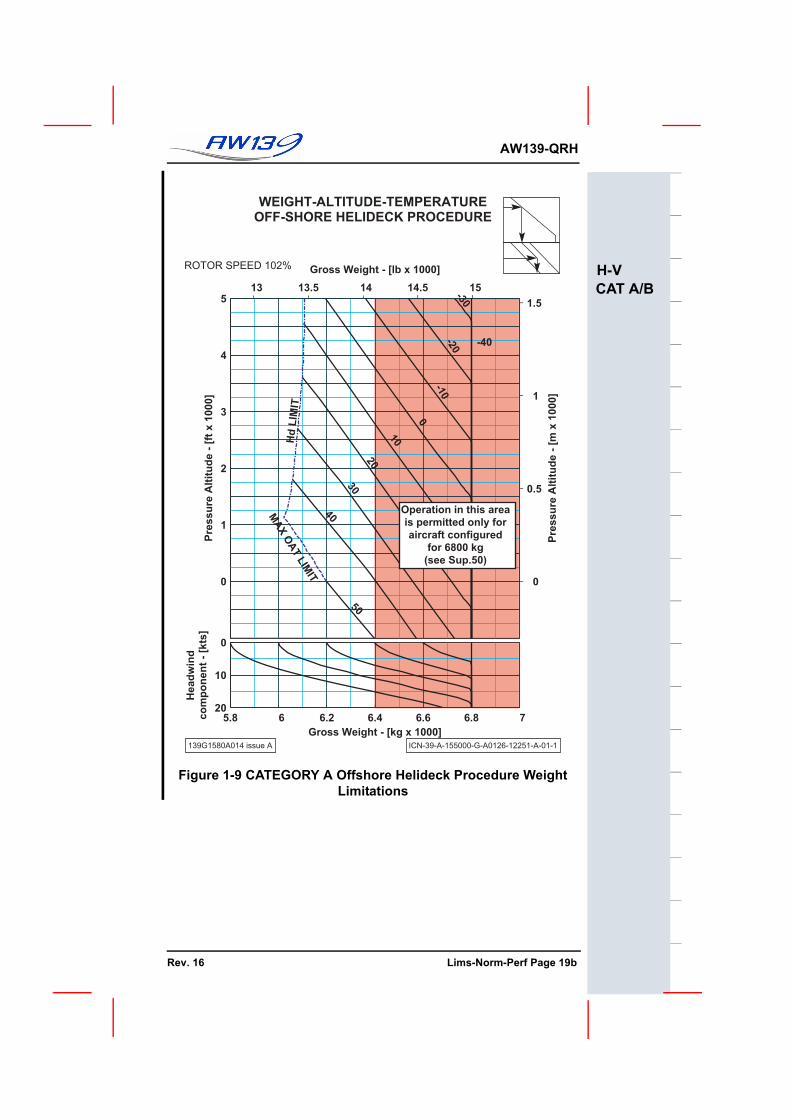
Figure 1-9 CATEGORY A Offshore Helideck Procedure Weight Limitations
139G1580A014 issue A ICN-39-A-155000-G-A0126-12251-A-01-1
13 13.5 14 14.5 15
0
0.5
1
1.5
Gross Weight - [lb x 1000]
Pre
ss
ure
Alt
itu
de
- [
m x
10
00
]
0
1
2
3
4
5
Pre
ss
ure
Alt
itu
de
- [
ft x
10
00
]
-40-30
-20
-10
0
10
20
30
40
50
MA
X
OA
T
LIM
IT
Hd
LIM
IT
5.8 6 6.2 6.4 6.6 6.8 7
0
10
20
Gross Weight - [kg x 1000]
Head
win
dco
mp
on
en
t -
[kts
]
Operation in this area
is permitted only for
aircraft configured
for 6800 kg
(see Sup.50)
UNMAINTAINED COPYFOR INFORMATION ONLY
Rev. 16 Lims-Norm-Perf Page 19b
F
AW139-QRH
This Page Left Blank Intentionally
UNMAINTAINED COPYOR INFORMATION ONLY
Lims-Norm-Perf Page 20
AW139-QRH
ENG FUELLUB HYD
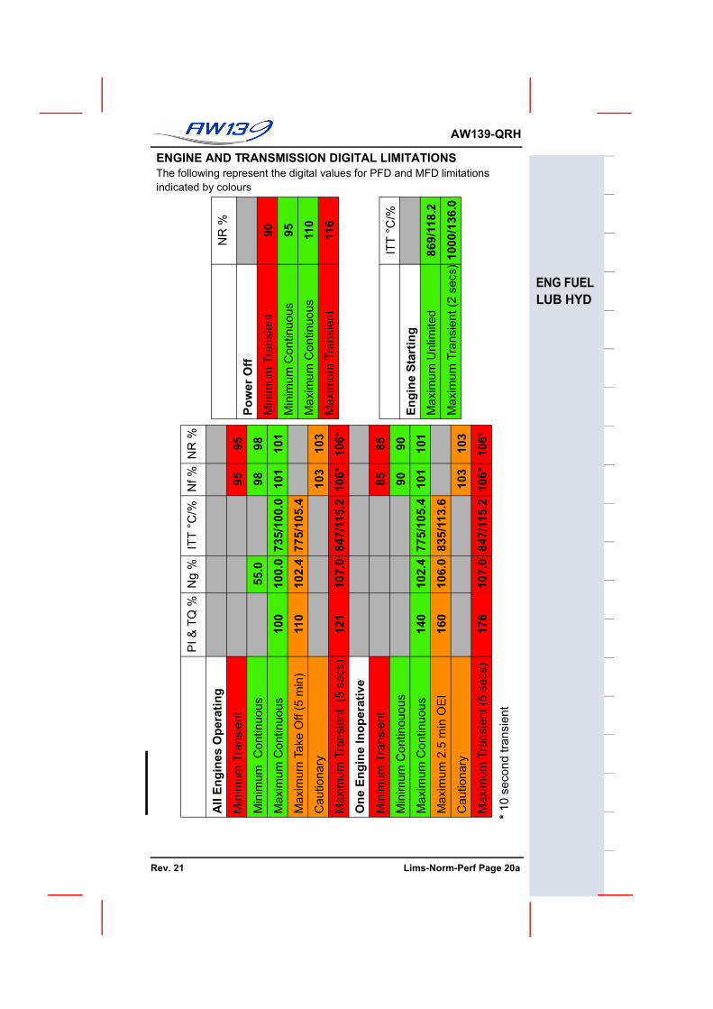
ENGINE AND TRANSMISSION DIGITAL LIMITATIONSThe following represent the digital values for PFD and MFD limitations indicated by colours
NR
% 90 95 110
116
ITT
°C/%
869/
118.
210
00/1
36.0
Pow
er O
ffM
inim
um T
rans
ient
Min
imum
Con
tinuo
us
Max
imum
Con
tinuo
us
Max
imum
Tra
nsie
nt
Engi
ne S
tart
ing
Max
imum
Unl
imite
d
Max
imum
Tra
nsie
nt (2
sec
s)
NR
% 95 98 101
103
106* 85 90 101
103
106*
Nf % 95 98 10
1
103
106* 85 90 101
103
106*
ITT
°C/%
735/
100.
077
5/10
5.4
847/
115.
2
775/
105.
483
5/11
3.6
847/
115.
2
Ng
%
55.0
100.
010
2.4
107.
0
102.
410
6.0
107.
0
PI&
TQ %
100
110
121
140
160
176
All
Engi
nes
Ope
ratin
gM
inim
um T
rans
ient
Min
imum
Con
tinuo
us
Max
imum
Con
tinuo
us
Max
imum
Tak
e O
ff (5
min
)
Cau
tiona
ry
Max
imum
Tra
nsie
nt (
5 se
cs)
One
Eng
ine
Inop
erat
ive
Min
imum
Tra
nsie
nt
Min
imum
Con
tinou
ous
Max
imum
Con
tinuo
us
Max
imum
2.5
min
OE
I
Cau
tiona
ry
Max
imum
Tra
nsie
nt (5
sec
s)
* 10
seco
nd tr
ansi
ent
UNMAINTAINED COPYFOR INFORMATION ONLY
Rev. 21 Lims-Norm-Perf Page 20a
F
AW139-QRH
ENG FUELLUB HYD
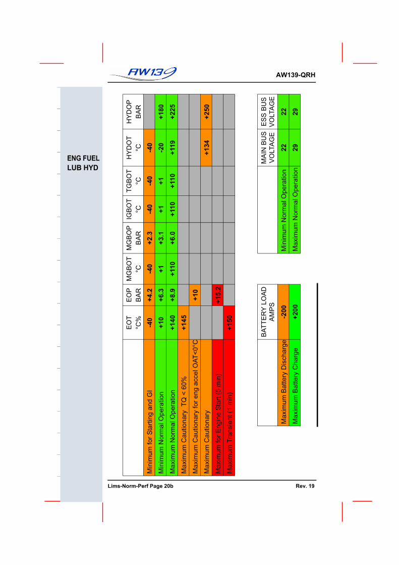
HY
DO
P
BA
R
+180
+225
+250
ES
S B
US
VO
LTA
GE
22 29
HY
DO
T °C -4
0-2
0+1
19
+134
MA
IN B
US
VO
LTA
GE
22 29
TGB
OT
°C -40
+1 +110
Min
imum
Nor
mal
Ope
ratio
n
Max
imum
Nor
mal
Ope
ratio
n
IGB
OT
°C -40
+1 +110
MG
BO
P
BA
R
+2.3
+3.1
+6.0
MG
BO
T °C -4
0+1 +1
10
EO
P
BA
R
+4.2
+6.3
+8.9
+10
+15.
2
BAT
TER
Y L
OA
DA
MP
S
-200
+200
EO
T °C
%
-40
+10
+140
+145
+150
Min
imum
for S
tarti
ng a
nd G
I
Min
imum
Nor
mal
Ope
ratio
n
Max
imum
Nor
mal
Ope
ratio
n
Max
imum
Cau
tiona
ry T
Q <
60%
Max
imum
Cau
tiona
ry fo
r eng
acc
el O
AT<0
°C
Max
imum
Cau
tiona
ry
Max
imum
for E
ngin
e St
art (
5 m
in)
Max
imum
Tra
nsie
nt (1
min
)
Max
imum
Bat
tery
Dis
char
ge
Max
imum
Bat
tery
Cha
rge
UNMAINTAINED COPYOR INFORMATION ONLY
Lims-Norm-Perf Page 20b Rev. 19
AW139-QRH
ENG FUELLUB HYD
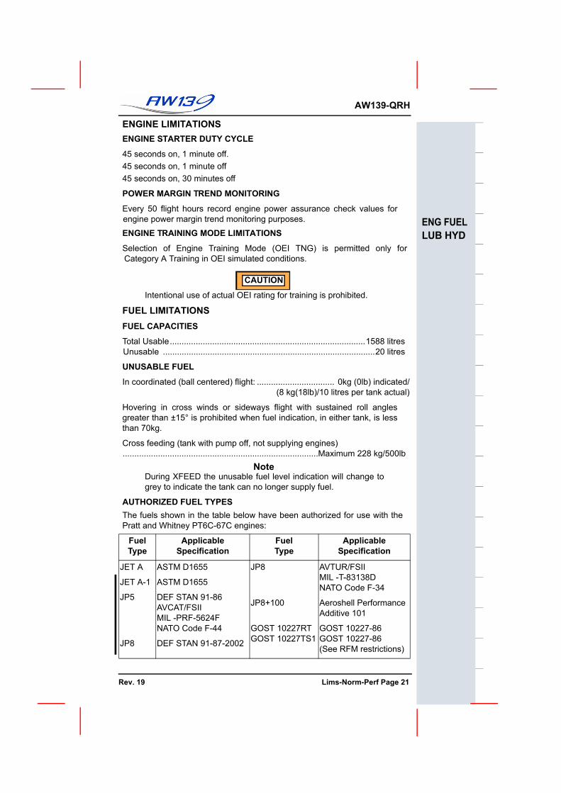
ENGINE LIMITATIONSENGINE STARTER DUTY CYCLE
45 seconds on, 1 minute off.45 seconds on, 1 minute off45 seconds on, 30 minutes off
POWER MARGIN TREND MONITORING
Every 50 flight hours record engine power assurance check values forengine power margin trend monitoring purposes.
ENGINE TRAINING MODE LIMITATIONS
Selection of Engine Training Mode (OEI TNG) is permitted only forCategory A Training in OEI simulated conditions.
CAUTION
Intentional use of actual OEI rating for training is prohibited.
FUEL LIMITATIONSFUEL CAPACITIES
Total Usable...................................................................................1588 litresUnusable ..........................................................................................20 litres
UNUSABLE FUEL
In coordinated (ball centered) flight: ................................. 0kg (0lb) indicated/(8 kg(18lb)/10 litres per tank actual)
Hovering in cross winds or sideways flight with sustained roll anglesgreater than ±15° is prohibited when fuel indication, in either tank, is lessthan 70kg.
Cross feeding (tank with pump off, not supplying engines)...................................................................................Maximum 228 kg/500lb
NoteDuring XFEED the unusable fuel level indication will change togrey to indicate the tank can no longer supply fuel.
AUTHORIZED FUEL TYPESThe fuels shown in the table below have been authorized for use with thePratt and Whitney PT6C-67C engines:
FuelType
ApplicableSpecification
FuelType
ApplicableSpecification
JET A
JET A-1
JP5
JP8
ASTM D1655
ASTM D1655
DEF STAN 91-86 AVCAT/FSIIMIL -PRF-5624FNATO Code F-44
DEF STAN 91-87-2002
JP8
JP8+100
GOST 10227RTGOST 10227TS1
AVTUR/FSIIMIL -T-83138DNATO Code F-34
Aeroshell Performance Additive 101
GOST 10227-86GOST 10227-86(See RFM restrictions)
UNMAINTAINED COPYFOR INFORMATION ONLY
Rev. 19 Lims-Norm-Perf Page 21
F
AW139-QRH
ENG FUELLUB HYD
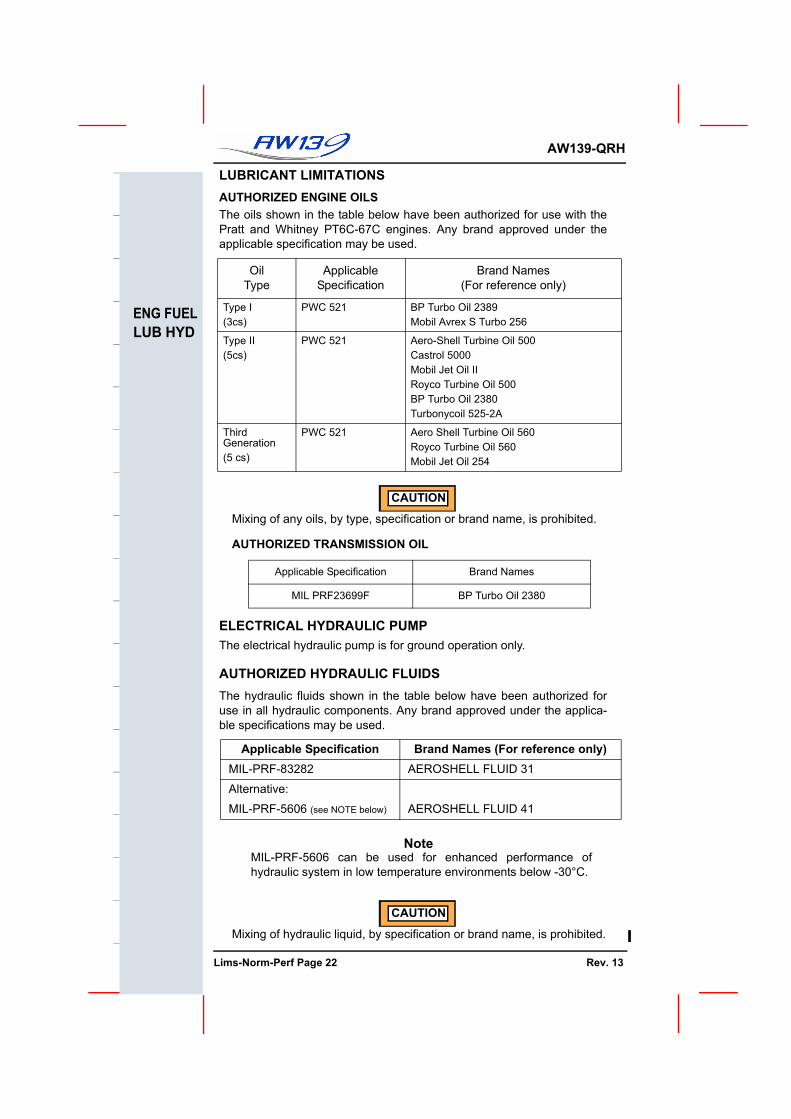
LUBRICANT LIMITATIONSAUTHORIZED ENGINE OILSThe oils shown in the table below have been authorized for use with thePratt and Whitney PT6C-67C engines. Any brand approved under theapplicable specification may be used.
CAUTION
Mixing of any oils, by type, specification or brand name, is prohibited.
AUTHORIZED TRANSMISSION OIL
ELECTRICAL HYDRAULIC PUMPThe electrical hydraulic pump is for ground operation only.
AUTHORIZED HYDRAULIC FLUIDSThe hydraulic fluids shown in the table below have been authorized foruse in all hydraulic components. Any brand approved under the applica-ble specifications may be used.
NoteMIL-PRF-5606 can be used for enhanced performance ofhydraulic system in low temperature environments below -30°C.
CAUTION
Mixing of hydraulic liquid, by specification or brand name, is prohibited.
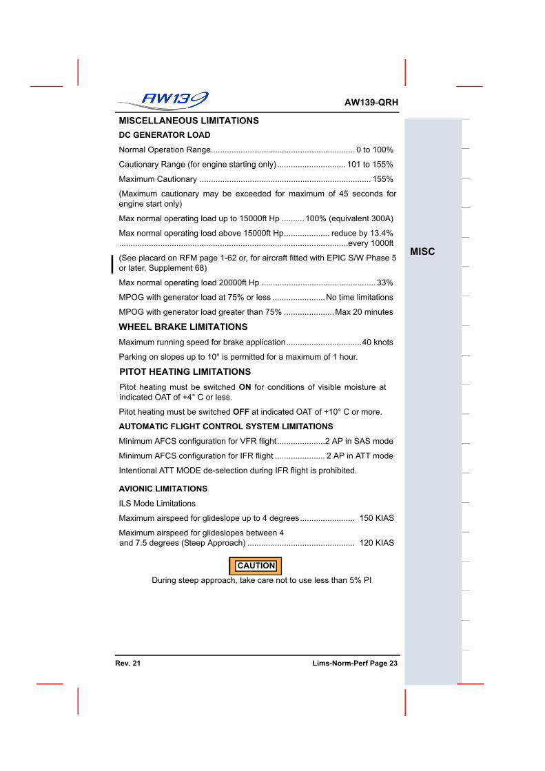
Normal Operation Range............................................................... 0 to 100%
Cautionary Range (for engine starting only).............................. 101 to 155%
Maximum Cautionary ........................................................................... 155%
(Maximum cautionary may be exceeded for maximum of 45 seconds forengine start only)
Max normal operating load up to 15000ft Hp ..........100% (equivalent 300A)
Max normal operating load above 15000ft Hp.................... reduce by 13.4%....................................................................................................every 1000ft
(See placard on RFM page 1-62 or, for aircraft fitted with EPIC S/W Phase 5or later, Supplement 68)
Max normal operating load 20000ft Hp .................................................. 33%
MPOG with generator load at 75% or less .......................No time limitations
MPOG with generator load greater than 75% ......................Max 20 minutes
WHEEL BRAKE LIMITATIONSMaximum running speed for brake application.................................40 knots
Parking on slopes up to 10° is permitted for a maximum of 1 hour.
PITOT HEATING LIMITATIONSPitot heating must be switched ON for conditions of visible moisture atindicated OAT of +4° C or less.
Pitot heating must be switched OFF at indicated OAT of +10° C or more.
AUTOMATIC FLIGHT CONTROL SYSTEM LIMITATIONS
Minimum AFCS configuration for VFR flight.....................2 AP in SAS mode
Minimum AFCS configuration for IFR flight ...................... 2 AP in ATT mode
Intentional ATT MODE de-selection during IFR flight is prohibited.
AVIONIC LIMITATIONS
ILS Mode Limitations
Maximum airspeed for glideslope up to 4 degrees........................ 150 KIAS
Maximum airspeed for glideslopes between 4 and 7.5 degrees (Steep Approach) ............................................... 120 KIAS
CAUTION
During steep approach, take care not to use less than 5% PI
UNMAINTAINED COPYFOR INFORMATION ONLY
Rev. 21 Lims-Norm-Perf Page 23
F
AW139-QRH
MISC
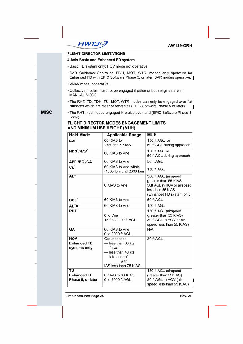
FLIGHT DIRECTOR LIMITATIONS4 Axis Basic and Enhanced FD system
• Basic FD system only: HOV mode not operative
• SAR Guidance Controller, TD/H, MOT, WTR, modes only operative forEnhanced FD with EPIC Software Phase 5, or later, SAR modes operative.
• VNAV mode inoperative.
• Collective modes must not be engaged if either or both engines are in MANUAL MODE
• The RHT, TD, TDH, TU, MOT, WTR modes can only be engaged over flatsurfaces which are clear of obstacles (EPIC Software Phase 5 or later)
• The RHT must not be engaged in cruise over land (EPIC Software Phase 4 only)
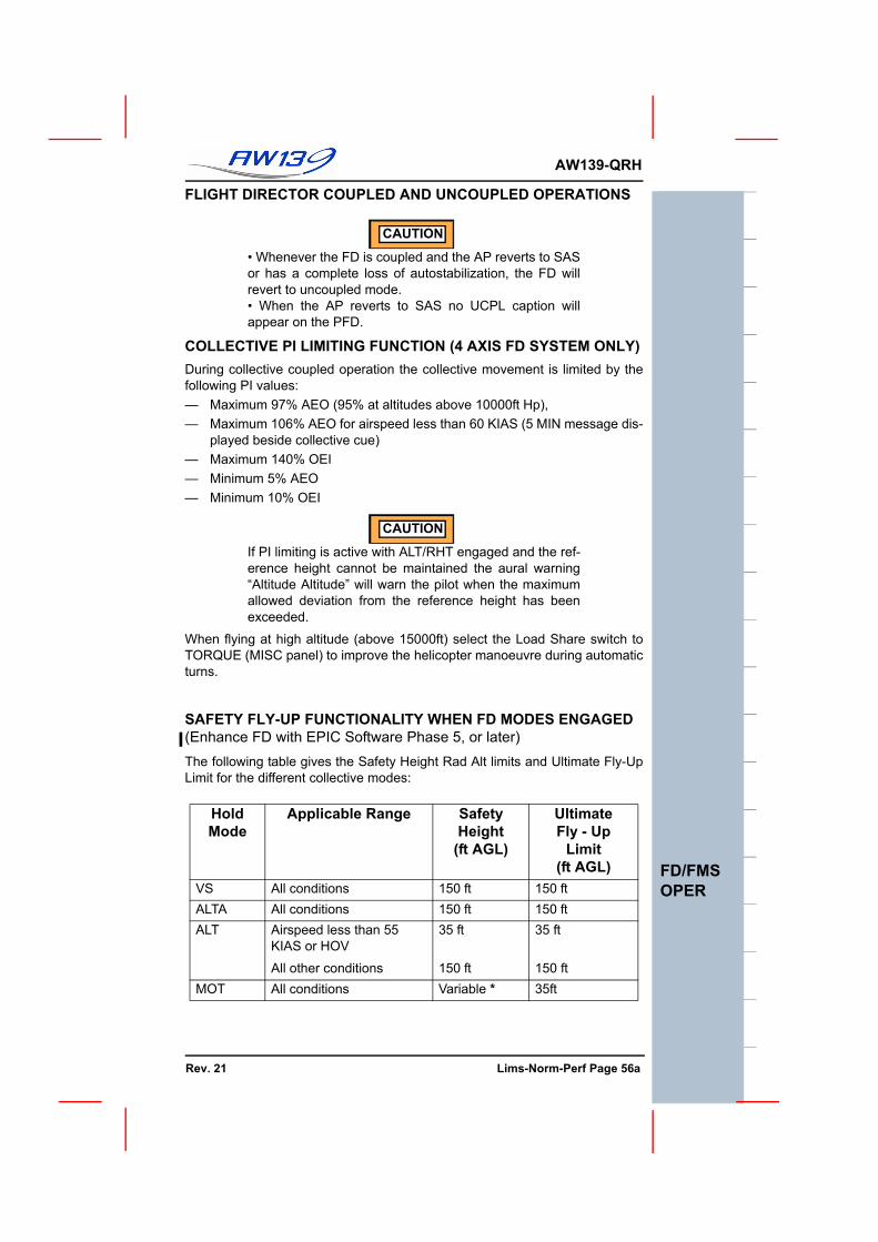
FLIGHT DIRECTOR MODES ENGAGEMENT LIMITS AND MINIMUM USE HEIGHT (MUH)Hold Mode Applicable Range MUHIAS* 60 KIAS to
Vne less 5 KIAS150 ft AGL or 50 ft AGL during approach
HDG*/NAV*60 KIAS to Vne 150 ft AGL or
50 ft AGL during approach
APP*/BC*/GA* 60 KIAS to Vne 50 ft AGL
VS* 60 KIAS to Vne within -1500 fpm and 2000 fpm 150 ft AGL
ALT
0 KIAS to Vne
300 ft AGL (airspeedgreater than 55 KIAS50ft AGL in HOV or airspeedless than 55 KIAS(Enhanced FD system only)
DCL* 60 KIAS to Vne 50 ft AGL
ALTA* 60 KIAS to Vne 150 ft AGLRHT
0 to Vne 15 ft to 2000 ft AGL
150 ft AGL (airspeed greater than 55 KIAS)30 ft AGL in HOV or air-speed less than 55 KIAS)
GA 60 KIAS to Vne0 to 2000 ft AGL
N/A
HOVEnhanced FD systems only
Groundspeed — less than 60 kts forward— less than 40 kts lateral or aft
withIAS less than 75 KIAS
30 ft AGL
TUEnhanced FDPhase 5, or later
0 KIAS to 60 KIAS0 to 2000 ft AGL
150 ft AGL (airspeedgreater than 55KIAS)30 ft AGL in HOV (air-speed less than 55 KIAS)
UNMAINTAINED COPYOR INFORMATION ONLY
Lims-Norm-Perf Page 24 Rev. 21
AW139-QRH
MISC
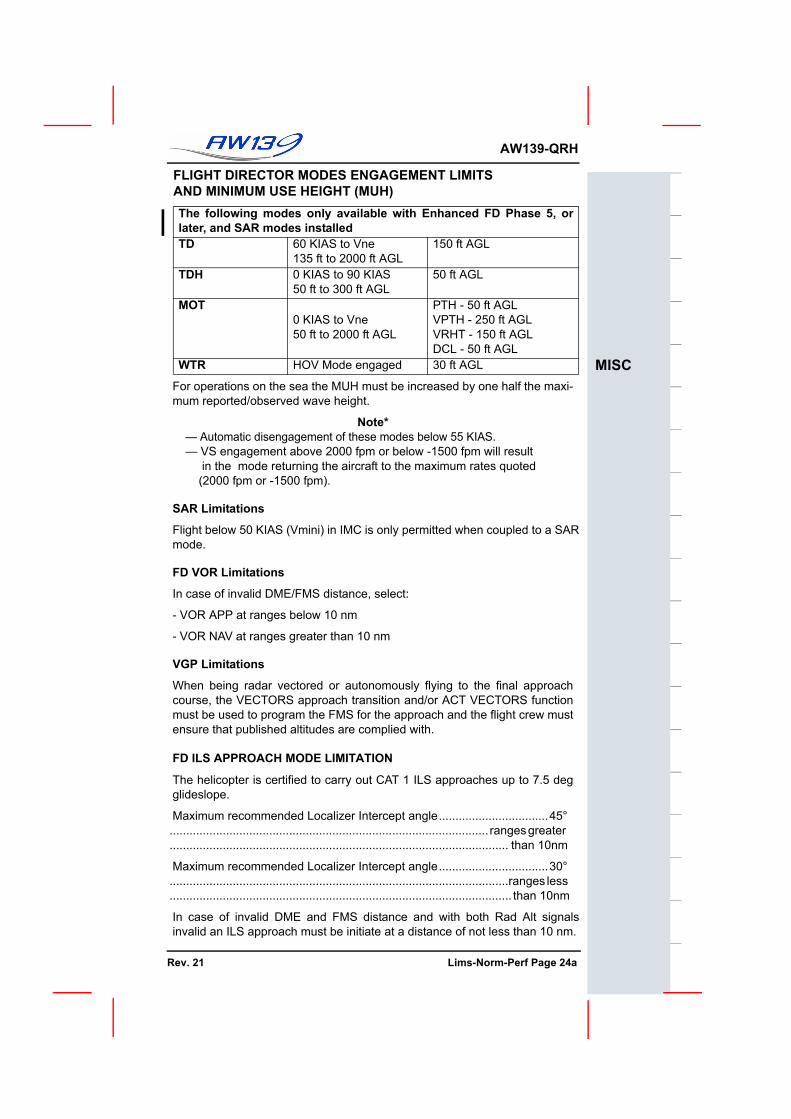
For operations on the sea the MUH must be increased by one half the maxi-mum reported/observed wave height.
Note*— Automatic disengagement of these modes below 55 KIAS.— VS engagement above 2000 fpm or below -1500 fpm will result in the mode returning the aircraft to the maximum rates quoted (2000 fpm or -1500 fpm).
SAR Limitations
Flight below 50 KIAS (Vmini) in IMC is only permitted when coupled to a SARmode.
FD VOR Limitations
In case of invalid DME/FMS distance, select:
- VOR APP at ranges below 10 nm
- VOR NAV at ranges greater than 10 nm
VGP Limitations
When being radar vectored or autonomously flying to the final approachcourse, the VECTORS approach transition and/or ACT VECTORS functionmust be used to program the FMS for the approach and the flight crew mustensure that published altitudes are complied with.
FD ILS APPROACH MODE LIMITATION
The helicopter is certified to carry out CAT 1 ILS approaches up to 7.5 degglideslope.
Maximum recommended Localizer Intercept angle.................................45° ................................................................................................ ranges greater ...................................................................................................... than 10nm
Maximum recommended Localizer Intercept angle.................................30° ......................................................................................................ranges less ....................................................................................................... than 10nm
In case of invalid DME and FMS distance and with both Rad Alt signalsinvalid an ILS approach must be initiate at a distance of not less than 10 nm.
The following modes only available with Enhanced FD Phase 5, orlater, and SAR modes installedTD 60 KIAS to Vne
135 ft to 2000 ft AGL150 ft AGL
TDH 0 KIAS to 90 KIAS50 ft to 300 ft AGL
50 ft AGL
MOT0 KIAS to Vne50 ft to 2000 ft AGL
PTH - 50 ft AGLVPTH - 250 ft AGLVRHT - 150 ft AGLDCL - 50 ft AGL
WTR HOV Mode engaged 30 ft AGL
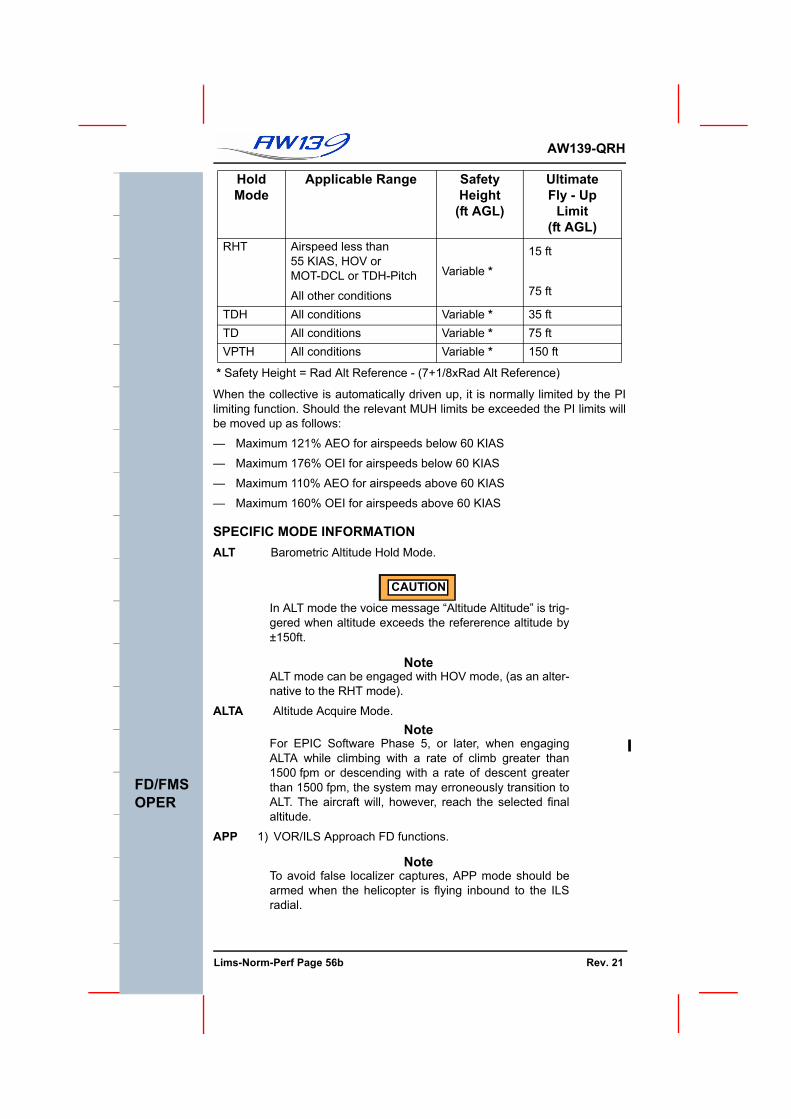
FLIGHT DIRECTOR MODES ENGAGEMENT LIMITS AND MINIMUM USE HEIGHT (MUH)
UNMAINTAINED COPYFOR INFORMATION ONLY
Rev. 21 Lims-Norm-Perf Page 24a
F
AW139-QRH
MISC
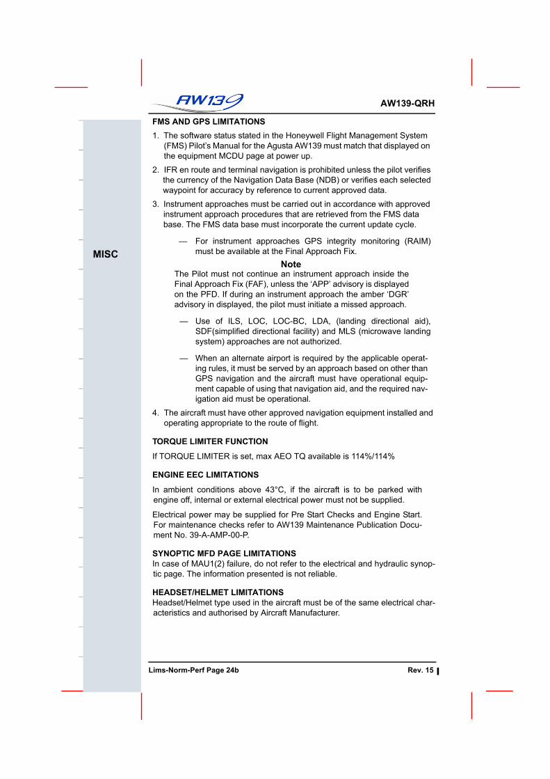
FMS AND GPS LIMITATIONS1. The software status stated in the Honeywell Flight Management System
(FMS) Pilot’s Manual for the Agusta AW139 must match that displayed on the equipment MCDU page at power up.
2. IFR en route and terminal navigation is prohibited unless the pilot verifies the currency of the Navigation Data Base (NDB) or verifies each selected waypoint for accuracy by reference to current approved data.
3. Instrument approaches must be carried out in accordance with approved instrument approach procedures that are retrieved from the FMS data base. The FMS data base must incorporate the current update cycle.
— For instrument approaches GPS integrity monitoring (RAIM)must be available at the Final Approach Fix.
NoteThe Pilot must not continue an instrument approach inside theFinal Approach Fix (FAF), unless the ‘APP’ advisory is displayedon the PFD. If during an instrument approach the amber ‘DGR’advisory in displayed, the pilot must initiate a missed approach.
— Use of ILS, LOC, LOC-BC, LDA, (landing directional aid),SDF(simplified directional facility) and MLS (microwave landingsystem) approaches are not authorized.
— When an alternate airport is required by the applicable operat-ing rules, it must be served by an approach based on other thanGPS navigation and the aircraft must have operational equip-ment capable of using that navigation aid, and the required nav-igation aid must be operational.
4. The aircraft must have other approved navigation equipment installed and operating appropriate to the route of flight.
TORQUE LIMITER FUNCTION
If TORQUE LIMITER is set, max AEO TQ available is 114%/114%
ENGINE EEC LIMITATIONS
In ambient conditions above 43°C, if the aircraft is to be parked withengine off, internal or external electrical power must not be supplied.
Electrical power may be supplied for Pre Start Checks and Engine Start.For maintenance checks refer to AW139 Maintenance Publication Docu-ment No. 39-A-AMP-00-P.
SYNOPTIC MFD PAGE LIMITATIONSIn case of MAU1(2) failure, do not refer to the electrical and hydraulic synop-tic page. The information presented is not reliable.
HEADSET/HELMET LIMITATIONSHeadset/Helmet type used in the aircraft must be of the same electrical char-acteristics and authorised by Aircraft Manufacturer.
UNMAINTAINED COPYOR INFORMATION ONLY
Lims-Norm-Perf Page 24b Rev. 15
AW139-QRH
GW EXT6800 kg
INCREASED GROSS WEIGHT 6800KG
General
For operations with Increased Gross Weight the aircraft must be in accor-dance with the requirements as detailed in RFM Supplement 50.
The following limitations are for operations between 6400 kg and 6800 kg,all other limitations remain unchanged.
Normal and Emergency Procedures remain unchanged
WEIGHT AND CENTER OF GRAVITY LIMITATIONSMaximum gross weight for towing ....................................................6450 kg
Maximum gross weight for taxiing ....................................................6800 kg
Maximum gross weight for take-off and landing...............................6800 kg
CAT B WAT Limitations chart ......................................... Figure GW EXT 5
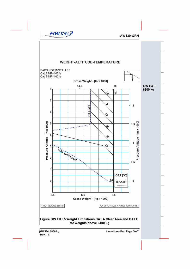
CAT A Clear Area WAT Limitations chart ....................... Figure GW EXT 5
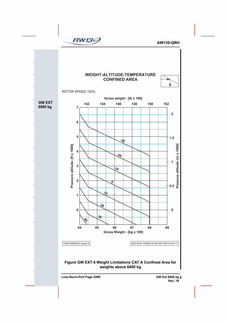
CAT A Confined Area WAT Limitations .......................... Figure GW EXT 6
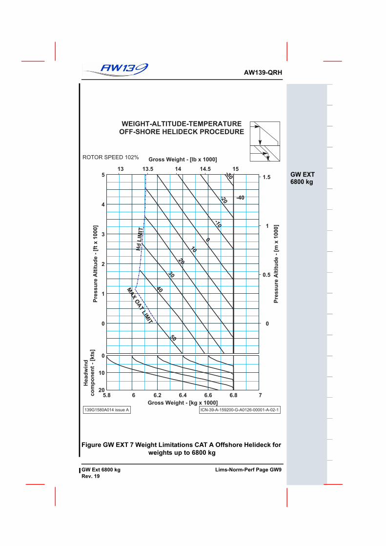
CAT A Off Shore WAT Limitations chart .......................... Figure GW EXT 7
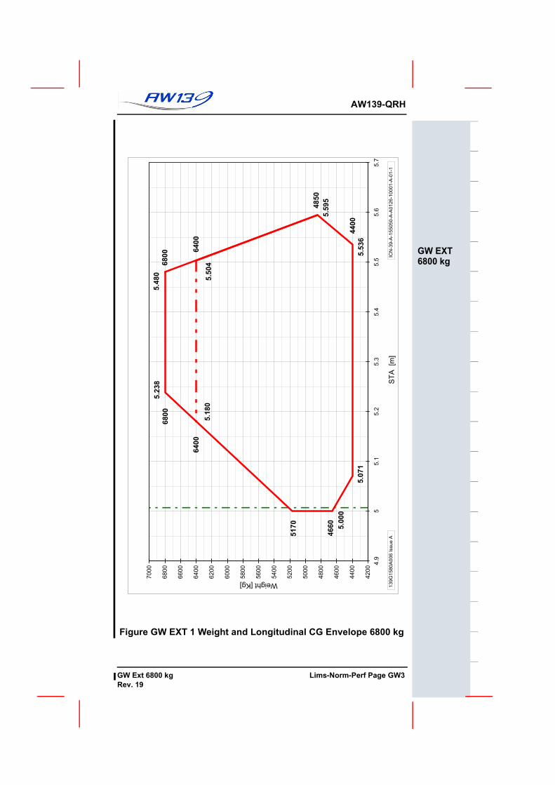
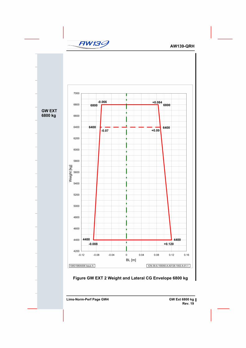
CENTER OF GRAVITYLongitudinal Limits........................................................... Figure GW EXT 1Lateral limits .................................................................... Figure GW EXT 2
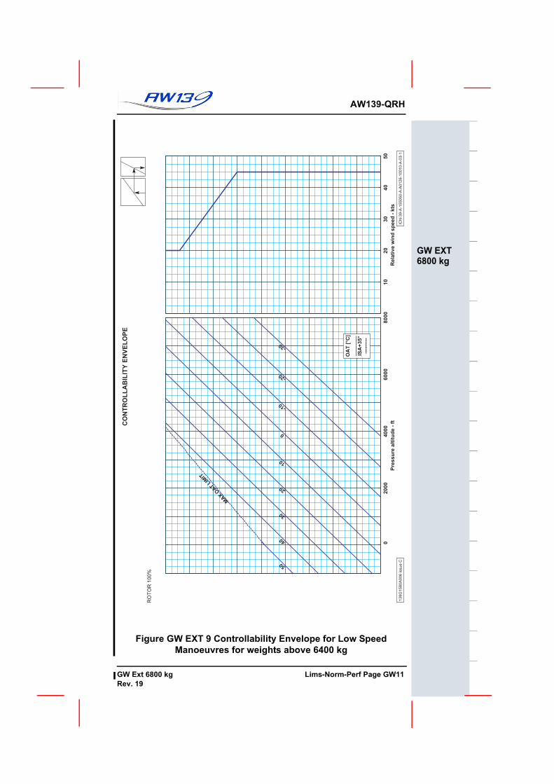
Maximum airspeed in sideward or rearward flight for weights above 6400 kg ................................................................. Figure GW EXT 9
Maximum allowable tailwind and crosswind for weights above 6400 kg ................................................................. Figure GW EXT 9
Maximum for emergency landing speed for weights above 6400kg(nose wheel locked in fore and aft position) .................................. 40 knots
Taxiing on grass surfaces at weights above 6400kg is prohibited
ALTITUDE LIMITATIONSMaximum operating altitude for weights above 6400kg ..... 8000 ft Hp or Hd................................................................................... whichever comes first
AMBIENT AIR TEMPERATURE LIMITATIONS (OAT)Maximum and minimum air temperature limitations for operations above 6400 kg............................................... Figure GW EXT 4
CAT A MISCELLANEOUS LIMITATIONSOffshore Heliport / Helideck SizeMinimum demonstrated helideck size for Take-Off and Landing for weights between 6400 kg & 6800 kgTake Off .......................................................................Diameter 15 m (50 ft)
..........................................................................or 15 m x 15 m (50 ft x 50 ft)
Landing........................................................................Diameter 22 m (72 ft).......................................................................... or 22 m x 22 m (72 ft x 72 ft)
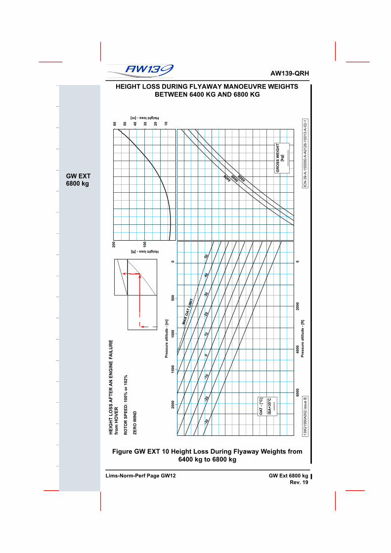
PERFORMANCE INFORMATIONSingle Engine Failure in Hover OGE Flyaway procedureweights between 6400 kg and 6800 kg ......................... Figure GW EXT 10
UNMAINTAINED COPYOR INFORMATION ONLY
Lims-Norm-Perf Page GW2 GW Ext 6800 kgRev. 20
AW139-QRH
GW EXT6800 kg
Figure GW EXT 1 Weight and Longitudinal CG Envelope 6800 kg
6400
6800
6800
5.2
38
4660
5170
5.0
71
5.0
00
4400
4850
5.5
36
6400
5.1
80
5.5
95
5.4
80
5.5
04
4200
4400
4600
4800
5000
5200
5400
5600
5800
6000
6200
6400
6600
6800
7000
4.9
55.1
5.2
5.3
5.4
5.5
5.6
5.7
ST
A [m
]
Weight [Kg]
IC
N-3
9-A
-155050-A
-A0126-1
0001-A
-01-1
139G
1580A
006 Issue A
UNMAINTAINED COPYFOR INFORMATION ONLY
GW Ext 6800 kg Lims-Norm-Perf Page GW3Rev. 19
F
AW139-QRH
GW EXT6800 kg
Figure GW EXT 2 Weight and Lateral CG Envelope 6800 kg
-0.066
+0.120
6800
4400
-0.088
6400
+0.09-0.07
4400
+0.084
6400
6800
4200
4400
4600
4800
5000
5200
5400
5600
5800
6000
6200
6400
6600
6800
7000
-0.12 -0.08 -0.04 0 0.04 0.08 0.12 0.16
BL [m]
Weig
ht [k
g]
139G1580A006 Issue A ICN-39-A-155050-A-A0126-1002-A-01-1
UNMAINTAINED COPYOR INFORMATION ONLY
Lims-Norm-Perf Page GW4 GW Ext 6800 kgRev. 19
AW139-QRH
GW EXT6800 kg
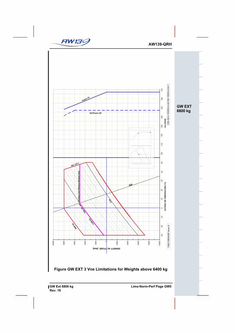
Figure GW EXT 3 Vne Limitations for Weights above 6400 kg
0 H
p
ISA
5000
Hp
8000
Hp
ISA +35°C
10
40
50
100
110
120
130
140
150
160
170
-30
-20
-10
020
30
Power O
n
OEI/Power Off
Take
Off
and
-10000
-8000
-6000
-4000
-20000
2000
4000
6000
8000
10000
-35
-25
-15
-55
15
25
35
45
55
65
75
85
95
105
115
125
OU
TS
IDE
AIR
TE
MP
ER
AT
UR
E [
°C
] V
ne [
KIA
S]
DENSITY ALTITUDE [feet]
IC
N-3
9-A
-155050-A
-A0126-1
0005-A
-04-1
139G
1580A
006 Issue A
Lan
din
g L
imit
Off
sh
ore H
elid
eck O
nly
UNMAINTAINED COPYFOR INFORMATION ONLY
GW Ext 6800 kg Lims-Norm-Perf Page GW5Rev. 19
F
AW139-QRH
GW EXT6800 kg
Figure GW EXT 4 Altitude- Temperature Limitations for Weights above 6400 kg
ALTITUDE-OATEnvelope
ICN-39-A-155050-A-A0126-01006-A-04-1
-200
0
200
400
600
800
1000
1200
1400
1600
1800
2000
2200
2400
Pre
ssu
re A
ltit
ud
e -
[m
]
-50 -40 -30 -20 -10 0 10 20 30 40 50 60
0
1000
2000
3000
4000
5000
6000
7000
8000
OAT - [°C]
Pre
ssu
re A
ltit
ud
e -
[ft
]
MIN
OA
T L
IMIT
MA
X O
AT
LIM
IT
Hd
LIM
IT 8
000
ft
Hd L
IMIT 8
000
ft
Hd L
IMIT 5
000 ft
Off-Shore ENVELOPE
Cat.A ENVELOPE
UNMAINTAINED COPYOR INFORMATION ONLY
Lims-Norm-Perf Page GW6 GW Ext 6800 kgRev. 19
AW139-QRH
GW EXT6800 kg
Figure GW EXT 5 Weight Limitations CAT A Clear Area and CAT B for weights above 6400 kg
WEIGHT-ALTITUDE-TEMPERATURE
EAPS NOT INSTALLED
Cat.A NR=102%
Cat.B NR=100%
139G1580A006 issue C ICN-39-A-155050-A-A0126-10007-A-03-1
14.5 15
0
0.5
1
1.5
2
Gross Weight - [lb x 1000]
Pre
ss
ure
Alt
itu
de
- [
m x
10
00
]
6.4 6.6 6.8
0
1
2
3
4
5
6
7
8
Gross Weight - [kg x 1000]
Pre
ss
ure
Alt
itu
de
- [
ft x
10
00
]
-20-10
0
10
20
30
40
50
MAX
OAT
LIMIT
Hd
LIM
IT
OAT [°C]_______ISA+35°---------
UNMAINTAINED COPYFOR INFORMATION ONLY
GW Ext 6800 kg Lims-Norm-Perf Page GW7Rev. 19
F
AW139-QRH
GW EXT6800 kg
Figure GW EXT 6 Weight Limitations CAT A Confined Area for weights above 6400 kg
WEIGHT-ALTITUDE-TEMPERATURECONFINED AREA
ROTOR SPEED 102%
139G1580A012 issue A ICN-39-A-155050-G-A0126-10014-A-01-1
142 144 146 148 150 152
0
0.5
1
1.5
2
Gross weight - [lb x 100]
Pre
ssu
re a
ltit
ud
e-
[m x
1000]
64 65 66 67 68 69
0
1
2
3
4
5
6
7
Gross Weight - [kg x 100]
Pre
ssu
re a
ltit
ud
e-
[ft
x 1
000]
-30
-20
-10
0
10
20
3040
UNMAINTAINED COPYOR INFORMATION ONLY
Lims-Norm-Perf Page GW8 GW Ext 6800 kgRev. 19
AW139-QRH
GW EXT6800 kg
Figure GW EXT 7 Weight Limitations CAT A Offshore Helideck for weights up to 6800 kg
139G1580A014 issue A ICN-39-A-159200-G-A0126-00001-A-02-1
13 13.5 14 14.5 15
0
0.5
1
1.5
Gross Weight - [lb x 1000]
Pre
ssu
re A
ltit
ud
e -
[m
x 1
000]
0
1
2
3
4
5
Gross Weight - [kg x 1000]
Pre
ssu
re A
ltit
ud
e -
[ft
x 1
000]
-40
-30
-20
-10
0
10
20
30
40
50
MA
X
OA
T
LIM
IT
Hd
LIM
IT
5.8 6 6.2 6.4 6.6 6.8 7
0
10
20
Gross Weight - [kg x 1000]
Head
win
dco
mp
on
en
t -
[kts
]
UNMAINTAINED COPYFOR INFORMATION ONLY
GW Ext 6800 kg Lims-Norm-Perf Page GW9Rev. 19
F
AW139-QRH
GW EXT6800 kg
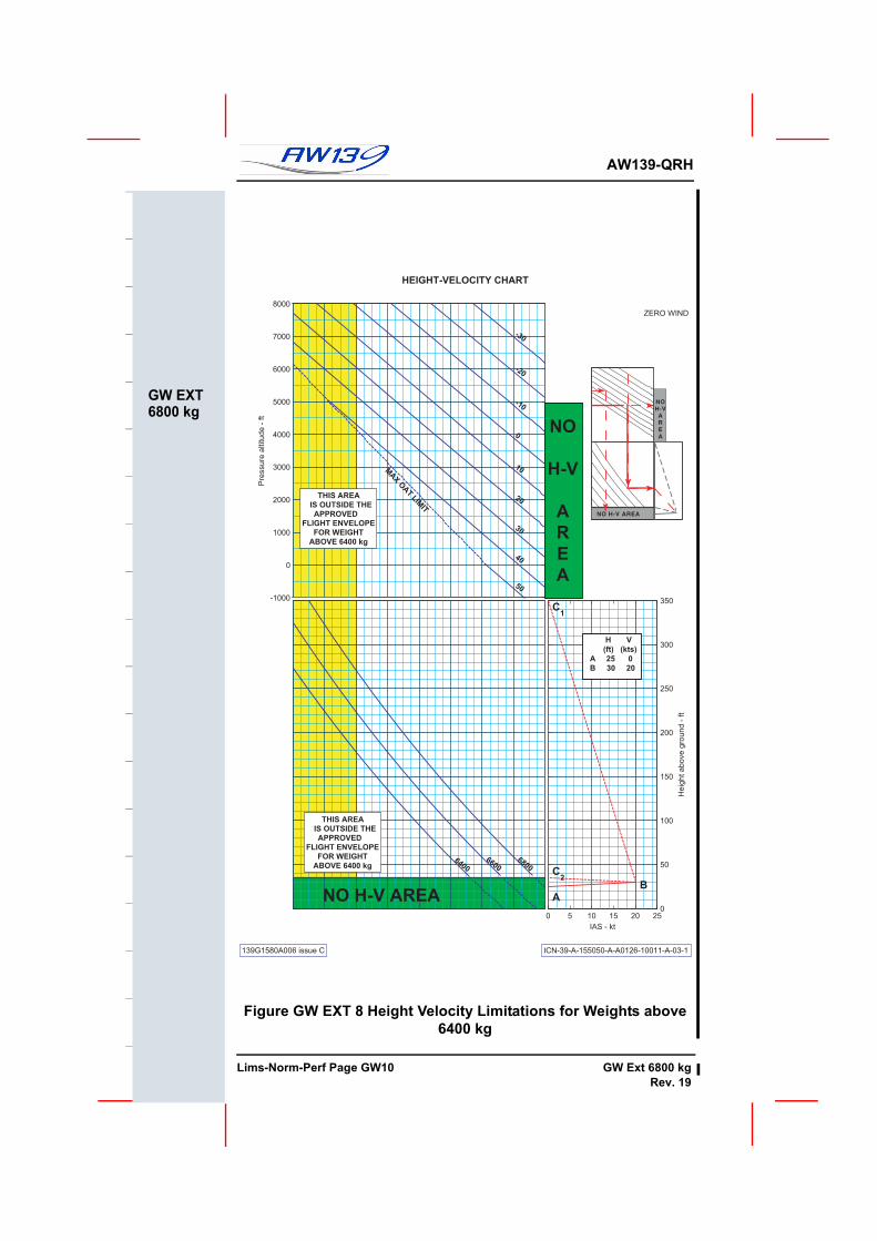
Figure GW EXT 8 Height Velocity Limitations for Weights above 6400 kg
HEIGHT-VELOCITY CHART
ZERO WIND
139G1580A006 issue C ICN-39-A-155050-A-A0126-10011-A-03-1
-1000
0
1000
2000
3000
4000
5000
6000
7000
8000
Pre
ssu
re a
ltitu
de
- ft
MAX
OAT LIM
IT
-30
-20
-10
0
10
20
30
40
50
THIS AREA
IS OUTSIDE THE
APPROVED
FLIGHT ENVELOPE
FOR WEIGHT
ABOVE 6400 kg
64006600
6800
NO H-V AREA
THIS AREA
IS OUTSIDE THE
APPROVED
FLIGHT ENVELOPE
FOR WEIGHT
ABOVE 6400 kg
0 5 10 15 20 25
0
50
100
150
200
250
300
350
IAS - kt
He
igh
t a
bo
ve
gro
un
d -
ft
AB
C2
C1
NO H-V AREA
NOH-V
AREA
NO
H-V
A
R
E
A
H V
(ft) (kts)
A 25 0
B 30 20
UNMAINTAINED COPYOR INFORMATION ONLY
Lims-Norm-Perf Page GW10 GW Ext 6800 kgRev. 19
AW139-QRH
GW EXT6800 kg
Figure GW EXT 9 Controllability Envelope for Low Speed Manoeuvres for weights above 6400 kg
CO
NT
RO
LL
AB
ILIT
Y E
NV
EL
OP
E
RO
TO
R 1
00%
13
9G
15
80
A0
06
issu
e C
ICN
-39
-A-1
55
05
0-A
-A0
12
6-1
00
10
-A-0
3-1
0
2000
4000
6000
8000
Pre
ssu
re a
ltit
ud
e -
ft
MAX O
AT L
IMIT
-30
-20
-10
0
10
20
30
40
50
OA
T [
°C]
_______
ISA
+35°
----
----
-
10
20
30
40
50
Rela
tive w
ind
sp
eed
- k
ts
UNMAINTAINED COPYFOR INFORMATION ONLY
GW Ext 6800 kg Lims-Norm-Perf Page GW11Rev. 19
F
AW139-QRH
GW EXT6800 kg
HEIGHT LOSS DURING FLYAWAY MANOEUVRE WEIGHTS BETWEEN 6400 KG AND 6800 KG
Figure GW EXT 10 Height Loss During Flyaway Weights from 6400 kg to 6800 kg
139G
1560
A00
2 is
sue
BIC
N-3
9-A
-155
050-
A-A
0126
-100
13-A
-02-
1
0
500
1000
1500
2000
Pres
sure
alti
tude
- [m
]
20
30
40
50
60
Height loss - [m]
0
2000
4000
6000
Pres
sure
alti
tude
- [ft
]
MAX
O
AT L
IMIT
-30
-20
-10
010
2030
4050
OAT
- [°
C]
____
____
ISA
+35°
C---
----
6400
6600
6800
GR
OSS
WEI
GH
T[k
g]__
____
__
100
200
Height loss - [ft]
10
HEI
GH
T LO
SSA
FTER
AN
EN
GIN
E FA
ILU
RE
from
HO
VER
ZER
O W
IND
RO
TOR
SPE
ED: 1
00%
or 1
02%
UNMAINTAINED COPYOR INFORMATION ONLY
Lims-Norm-Perf Page GW12 GW Ext 6800 kgRev. 19
AW139-QRH
ALT EXT9 PAX
T-O AND LANDING ALTITUDE EXTENSION ( 9 PASSENGERSEAT CONFIGURATION )
GeneralFor operations within the Take Off and Landing Altitude Extension the aircraftmust be in accordance with the requirements as detailed in RFM Supplement 51.The following Limitations are for operations in the T-O and Landing AltitudeExtension, all other limitations remain unchanged. Normal and Emergency Procedures remain unchanged.
NUMBER OF OCCUPANTSThe total number of occupants in passenger cabin shall not exceed ..........9
WEIGHT LIMITATIONSCAT B WAT T-O and Landing see Hover Ceiling IGE @ TOP......................................................................................... Figure ALT EXT 1
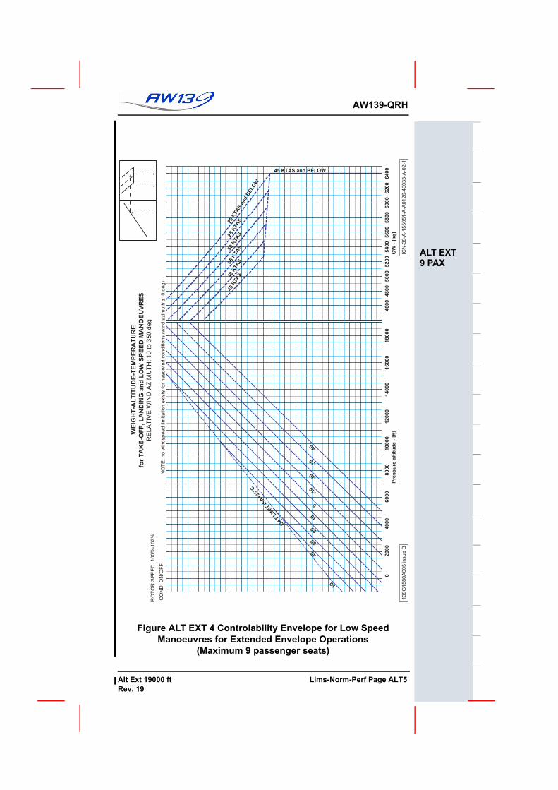
AIRSPEED LIMITATIONSMaximum airspeed in sideward or rearward flight .......... Figure ALT EXT 4.....................................................................................(for operations above ......................................................................................14000 ft NR must be ...................................................................................................set to 102%)
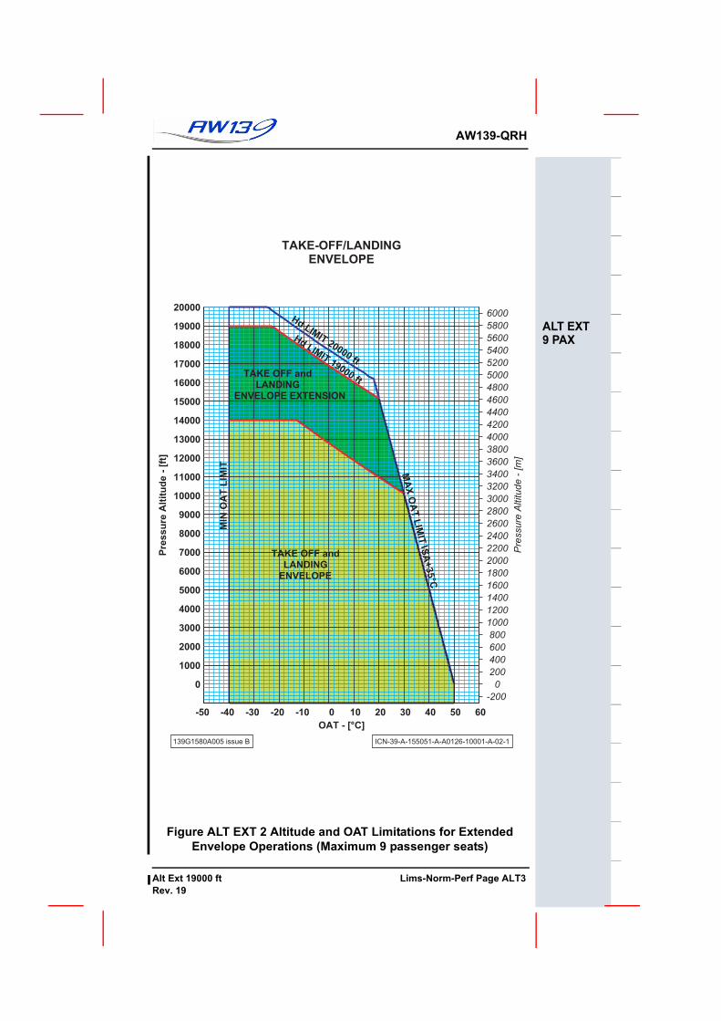
AMBIENT AIR TEMPERATURE LIMITATIONS (OAT)Maximum and minimum air temperature limitation ......... Figure ALT EXT 2
HEIGHT- VELOCITY LIMITATIONSHeight velocity diagram is considered performanceinformation........................................................................ Figure ALT EXT 3
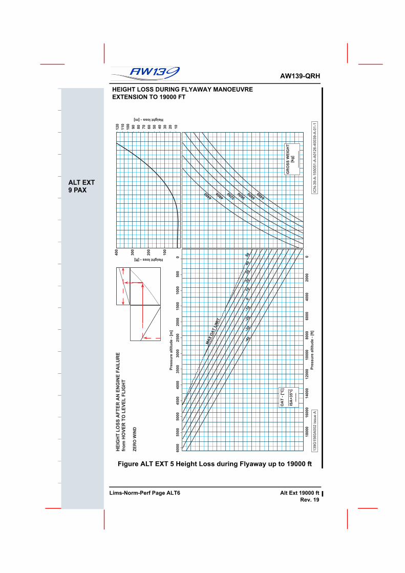
PERFORMANCE INFORMATIONSingle engine Failure in Hover OGE flyaway procedure Figure ALT EXT 5
ROTOR SPEED: 100%-102 % ZERO WIND WHEEL HEIGHT: 5 FTELECTRICAL LOAD: 600 A TOTALCOND ON: reduce weight by 50 kg
139G1580A005 ISSUE B ICN-39-A-155051-A-A0126-40001-A-02- 1
HD
LIM
IT 1
9000
ft
UNMAINTAINED COPYOR INFORMATION ONLY
Lims-Norm-Perf Page ALT2 Alt Ext 19000 ftRev. 19
AW139-QRH
ALT EXT9 PAX
Figure ALT EXT 2 Altitude and OAT Limitations for Extended Envelope Operations (Maximum 9 passenger seats)
TAKE-OFF/LANDINGENVELOPE
139G1580A005 issue B ICN-39-A-155051-A-A0126-10001-A-02-1
-200
0
200
400
600
800
1000
1200
1400
1600
1800
2000
2200
2400
2600
2800
3000
3200
3400
3600
3800
4000
4200
4400
4600
4800
5000
5200
5400
5600
5800
6000
Pre
ssu
re A
ltitu
de
- [
m]
-50 -40 -30 -20 -10 0 10 20 30 40 50 60
0
1000
2000
3000
4000
5000
6000
7000
8000
9000
10000
11000
12000
13000
14000
15000
16000
17000
18000
19000
20000
OAT - [°C]
Pre
ssu
re A
ltit
ud
e -
[ft
]
MIN
OA
T L
IMIT M
AX
OA
T L
IMIT
ISA
+35°C
Hd LIMIT 20000 ft
Hd LIMIT 19000
ft
TAKE OFF andLANDING
ENVELOPE
ENVELOPE EXTENSION
TAKE OFF andLANDING
UNMAINTAINED COPYFOR INFORMATION ONLY
Alt Ext 19000 ft Lims-Norm-Perf Page ALT3Rev. 19
F
AW139-QRH
ALT EXT9 PAX
Figure ALT EXT 3 Height Velocity Chart for Extended Envelope Operations (Maximum 9 passenger seats)
HEIGHT-VELOCITY CHART
ZERO WIND
139G1580A005 issue A ICN-39-A-155051-A-A0126-40035-A-01-1
0
2000
4000
6000
8000
10000
12000
14000
16000
18000
Pre
ssu
re a
ltitu
de
- f
t
MAX
OAT LIM
IT
-40
-30
-20
-10
0
10
20
30
40
4400
4600
4800
5000
5200
5400
5600
5800
6000
6200
6400
NO H-V AREA0 5 10 15 20 25
0
50
100
150
200
250
300
350
IAS - kt
He
igh
t a
bo
ve
gro
un
d -
ft
AB
C2
C1
H V
(ft) (kts)
A 25 0
B 30 20
GR
OS
S W
EIG
HT [k
g]
NO H-V AREA
NOH-V
AREA
NO
H-V
A
R
E
A
UNMAINTAINED COPYOR INFORMATION ONLY
Lims-Norm-Perf Page ALT4 Alt Ext 19000 ftRev. 19
AW139-QRH
ALT EXT9 PAX
Figure ALT EXT 4 Controlability Envelope for Low Speed Manoeuvres for Extended Envelope Operations
(Maximum 9 passenger seats)
WE
IGH
T-A
LT
ITU
DE
-TE
MP
ER
AT
UR
E
RO
TO
R S
PE
ED
: 1
00
%-1
02
%
CO
ND
: O
N/O
FF
13
9G
15
80
A0
05
issu
e B
ICN
-39
-A-1
55
05
1-A
-A0
12
6-4
00
33
-A-0
2-1
0 2
00
0 4
00
0 6
00
0 8
00
01
00
00
12
00
01
40
00
16
00
01
80
00
Pre
ss
ure
alt
itu
de
- [
ft]
OA
T
LIM
IT IS
A+3
5°C
-40
-30
-20
-10
0
10
20
30
40
50
46
00
48
00
50
00
52
00
54
00
56
00
58
00
60
00
62
00
64
00
GW
- [
kg
]
45 KTAS and BELOW
45
KTA
S40
KTA
S35
KTA
S30
KTA
S25
KTA
S20
KTA
S a
nd B
ELO
W
for
TA
KE
-OF
F, L
AN
DIN
G a
nd
LO
W S
PE
ED
MA
NO
EU
VR
ES
RE
LA
TIV
E W
IND
AZ
IMU
TH
: 10 to 3
50 d
eg
NO
TE
: n
o w
ind
sp
ee
d lim
ita
tio
n e
xis
ts f
or
he
ad
win
d c
on
ditio
ns (
win
d a
zim
uth
±1
0 d
eg
)
UNMAINTAINED COPYFOR INFORMATION ONLY
Alt Ext 19000 ft Lims-Norm-Perf Page ALT5Rev. 19
F
AW139-QRH
ALT EXT9 PAX
HEIGHT LOSS DURING FLYAWAY MANOEUVRE EXTENSION TO 19000 FT
Figure ALT EXT 5 Height Loss during Flyaway up to 19000 ft
HE
IGH
T L
OS
S A
FT
ER
AN
EN
GIN
E F
AIL
UR
E
fro
m H
OV
ER
TO
LE
VE
L F
LIG
HT
ZE
RO
WIN
D
13
9G
15
60
A0
02
issu
e A
ICN
-39
-A-1
55
05
1-A
-A0
12
6-4
00
39
-A-0
1-1
0
50
01
00
01
50
02
00
02
50
03
00
03
50
04
00
04
50
05
00
05
50
06
00
0
Pre
ss
ure
alt
itu
de
- [
m]
20
30
40
50
60
70
80
90
10
0
11
0
12
0
Height loss - [m]
0 2
00
0 4
00
0 6
00
0 8
00
01
00
00
12
00
01
40
00
16
00
01
80
00
Pre
ss
ure
alt
itu
de
- [
ft]
MA
X O
AT L
IMIT
-40
-30
-20
-10
010
2030
4050
OA
T -
[°C
]
__
__
__
__
ISA
+3
5°C
----
---
4400
4800
52005600
60006400
GR
OS
S W
EIG
HT
[kg
]
__
__
__
__
10
0
20
0
30
0
40
0
Height loss - [ft]
10
UNMAINTAINED COPYOR INFORMATION ONLY
Lims-Norm-Perf Page ALT6 Alt Ext 19000 ftRev. 19
AW139-QRH
EXTNCHECKS
NORMAL PROCEDURESGENERALThe following procedures are intended to ensure that the level of safetyrequired by the design and certification process is achieved.
NoteThroughout this Section, checks marked with a large are required onlybefore the first flight of the day. All other checks are to be carried out beforeeach flight.
Normal and standard conditions are assumed in these procedures.
The minimum and maximum limits, and the normal and cautionary operat-ing ranges are indicated on the PFD and MFD displays,
FLIGHT PLANNINGCAT B WEIGHT AND H-V DETERMINATION
Graphs are presented in Limitations to determine maximum weight for CATB Take Off/Landing/IGE manoeuvres (Figure 1-5) and to determine the H-V(Figure 1-4) avoid area diagram.
The order of flight planning is first to determine the CAT B weight for TakeOff and Landing at the ambient conditions then to confirm the H-V avoidarea diagram applicable for the weight chosen.
CATEGORY A PROCEDURESSee Supplement 12 for detailed information on CATEGORY A procedures.
LDP Rate of Descent................................................ Less than 350 ft/min
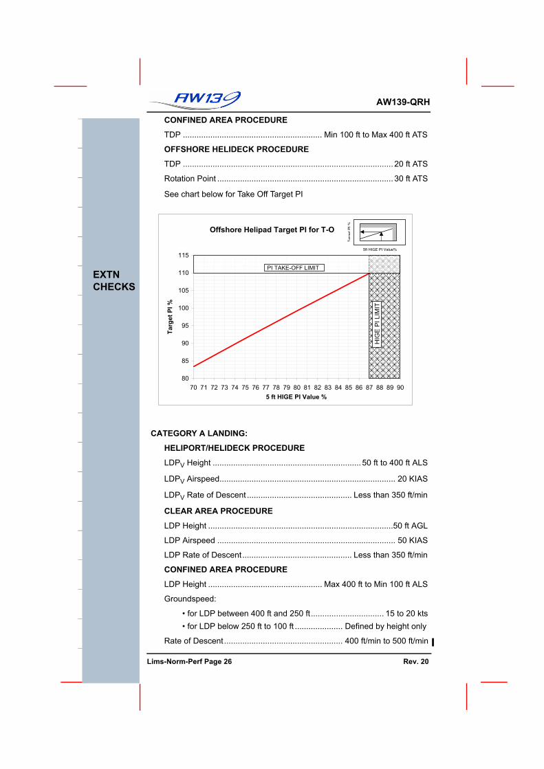
CONFINED AREA PROCEDURE
LDP Height .................................................. Max 400 ft to Min 100 ft ALS
Groundspeed:
• for LDP between 400 ft and 250 ft................................ 15 to 20 kts• for LDP below 250 ft to 100 ft ..................... Defined by height only
Rate of Descent.................................................... 400 ft/min to 500 ft/min
LDP Rate of descent .................................................................... 0 ft/min
GROSS WEIGHT AND CENTER OF GRAVITYDetermine both the take-off and estimated landing Gross Weight, Center ofGravity and verify that they are within approved envelope limits. The Weightand Balance and appropriate performance charts must be used to ascertainthe weight and balance data as follows:
- Consult RFM Section 6 - Weight and Balance
- Ascertain weight of fuel, oil, payload etc.
- Compute take off and anticipated gross landing weight
- Check helicopter centre of gravity (CG) position
- Confirm that the weight and CG limitations in Limitations are not exceeded
COLD WEATHER OPERATIONIf the helicopter is to remain parked outside with an OAT at or below -20°Cboth Main and Auxiliary batteries should be removed and stored in a heatedroom. Confirm batteries have been installed before flight