Page 1
NASA/TM--1999-209788
Unmanned Vehicle Guidance UsingVideo Camera/Vehicle Model
(MSFC Center Director's Discretionary Fund Final Report,
Project No. 97-23)
T. Sutherland
Marshall Space Right Center, Marshall Space Flight Center, Alabama
December 1999
https://ntrs.nasa.gov/search.jsp?R=20000011914 2020-04-20T21:34:49+00:00Z
Page 2
The NASA STI Program Office...in Profile
Since its founding, NASA has been dedicated to
the advancement of aeronautics and spacescience. The NASA Scientific and Technical
Information (STI) Program Office plays a key
part in helping NASA maintain this importantrole.
The NASA STI Program Office is operated by
Langley Research Center, the lead center forNASA's scientific and technical information. The
NASA STI Program Office provides access to the
NASA STI Database, the largest collection of
aeronautical and space science STI in the world. The
Program Office is also NASA's institutional
mechanism for disseminating the results of its
research and development activities. These results
are published by NASA in the NASA STI Report
Series, which includes the following report types:
TECHNICAL PUBLICATION. Reports of
completed research or a major significant phase
of research that present the restllts of NASA
programs and include extensive data or
theoretical analysis. Includes compilations of
significant scientific and technical data and
information deemed to be of continuing reference
value. NASA's counterpart of peer-reviewed
formal professional papers but has less stringent
limitations on manuscript length and extent of
graphic presentations.
TECHNICAL MEMORANDUM. Scientific and
technical findings that are preliminary or of
specialized interest, e.g., quick release reports,
working papers, and bibliographies that containminimal annotation. Does not contain extensive
analysis.
CONTRACTOR REPORT. Scientific and
technical findings by NASA-sponsored
contractors and grantees.
CONFERENCE PUBLICATION. Collected
papers from scientific and technical conferences,
symposia, seminars, or other meetings sponsored
or cosponsored by NASA.
SPECIAL PUBLICATION. Scientific, technical,
or historical information from NASA programs,
projects, and mission, often concerned with
subjects having substantial public interest.
TECHNICAL TRANSLATION.
English-language translations of foreign scientific
and technical material pertinent to NASA'smission.
Specialized services that complement the STI
Program Office's diverse offerings include creating
custom thesauri, building customized databases,
organizing and publishing research results...even
providing videos.
For more information about the NASA STI Program
Office, see the following:
• Access the NASA STI Program Home Page at
http://www.sti.nasa.gov
• E-mail your question via the Internet to
[email protected]
• Fax your question to the NASA Access Help
Desk at (301) 621-0134
• Telephone the NASA Access Help Desk at (301)621-0390
Write to:
NASA Access Help Desk
NASA Center for AeroSpace Information7121 Standard Drive
Hanover, MD 21076-1320
Page 3
N ASA / TM-- 1999-209788
Unmanned Vehicle Guidance UsingVideo Camera/Vehicle Model
(MSFC Center Director's Discretionary Fund Final Report,
Project No. 97-23)
T. Sutherland
Marshall Space Flight Center, Marshall Space Flight Center, Alabama
National Aeronautics and
Space Administration
Marshall Space Flight Center • MSFC, Alabama 35812
December 1999
Page 4
5
Available from:
NASA Center for AeroSpace lnfi)rmalion Nalional Technical lnformalion Se3wicc
7121 Standard Drive 5285 Port Royal Road
Hanover, MD 21076-1320 Springfield, VA 22161
(301 ) 621-0390 (703) 487-4650
Page 5
TABLE OF CONTENTS
l°
2.
3.
4.
5.
°
7.
INTRODUCTION ..................................................................................................................
DESCRIPTION .......................................................................................................................
APPROACH .............................................................................................................................
DEVELOPMENT ....................................................................................................................
ADVANCED VIDEO GRAPHICS ADAPTER SYSTEM SPECIFICATIONS .....................
5.1 Hardware .........................................................................................................................
5.2 Software ...........................................................................................................................
CONCLUSION ........................................................................................................................
FUTURE WORK .....................................................................................................................
REFERENCES ..................................................................................................................................
2
4
5
7
7
7
8
8
9
,.,
II1
Page 6
LIST OF FIGURES
°
2.
3.
4.
5.
6.
7.
Docking scenario for the basic VGS system ............................................................................
Current VGS system configuration ..........................................................................................
Current VGS image resolution--images as seen and after processing ....................................
VGS analog section .................................................................................................................
VGS C40 main and video mezzanine boards ..........................................................................
Advanced VGS new camera configuration ..............................................................................
Advanced VGS system overview .............................................................................................
1
2
3
3
5
6
6
----!-!i!i_i
iv
Page 7
LIST OF ACRONYMS
CCD
CDDF
DSP
EEPROM
EXVM
FFT
FPGA
NT
RAM
STS
UART
VGS
VME
charged coupled device
Center Director's Discretionary Fund
digital signal processor
electronically erasable programmable read only memory
experimental vector magnetograph
fast fourier transform
field programmable gate arrays
new technology
random access memory
Space Transportation System
universal asynchronous receiver/transmitter
video guidance sensor
versa module eurocard
v
Page 9
TECHNICAL MEMORANDUM
UNMANNED VEHICLE GUIDANCE USING VIDEO CAMERA/VEHICLE MODEL
(Center Director's Discretionary Fund Final Report, Project No. 97-23)
1. INTRODUCTION
The purpose of this Center Director's Discretionary Fund (CDDF) project was to improve the
state of the art of vehicle navigation by two methods: (,1) Improve current video guidance sensor (VGS)
capabilities by redesigning the video sensor assembly; and (2) create an algorithm development system
that could be used to produce a camera/vehicle modeling method for vehicIe tracking. Figure 1 depicts
the docking scenario for the basic VGS system.
Figure 1. Docking scenario for the basic VGS system.
Page 10
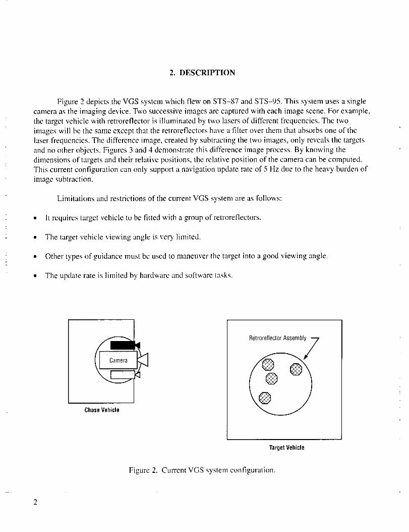
2. DESCRIPTION
Figure 2 depicts the VGS system which flew on STS-87 and STS-95. This system uses a single
camera as the imaging device. Two successive images are captured with each image scene. For example,
the target vehicle with retroreflector is illuminated by two lasers of different frequencies. The two
images will be the same except that the retroreflectors have a filter over them that absorbs one of the
laser frequencies. The difference image, created by subtracting the two images, only reveals the targets
and no other objects. Figures 3 and 4 demonstrate this difference image process. By knowing the
dinaensions of targets and their relative positions, the relative position of the camera can be computed.
This current configuration can only support a navigation update rate of 5 Hz due to the heavy burden of
image subtraction.
Limitations and restrictions of the current VGS system are as follows:
• It requires target vehicle to be fitted with a group of retroreflectors.
• The target vehicle viewing angle is very limited.
• Other types of guidance must be used to maneuver the target into a good viewing angle.
• The update rate is limited by hardware and software tasks.
Camera
ChaseVehicle
RetroreflectorAssembly
TargetVehicle
Figure 2. Current VGS system configuration.
Page 11
CCDA's Image
Images as Seen,andAfter Processing
+
CCDB's Image
ImageAfterProcessing
Figure 3. Current VGS image resolution--images as seen and after processing.
AnalOgccDSignalA]
AnalOgccDSignaIB1
FrameGrabber
FrameGrabber
Figure 4. VGS analog section.
3
Page 12
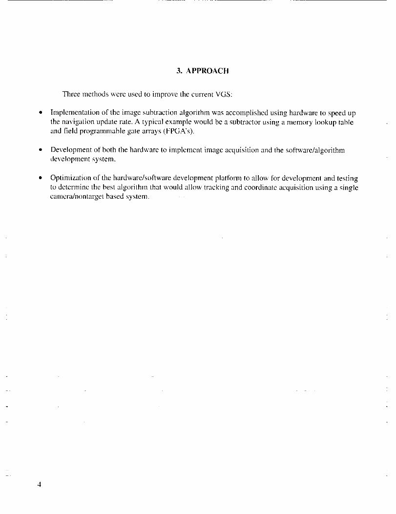
3. APPROACH
Three methods were used to improve the current VGS:
Implementation of the image subtraction algorithm was accomplished using hardware to speed up
the navigation update rate. A typical example would be a subtractor using a memory lookup table
and field programmable gate an'ays (FPGA's).
• Development of both the hardware to implement image acquisition and the software/algorithm
development system.
Optimization of the hardware/software development platform to allow for development and testing
to determine the best algorithm that would allow tracking and coordinate acquisition using a single
camera/nontmNet based system.
Page 13
4. DEVELOPMENT
The first 2 yr have been dedicated to designing electronic hardware, selecting optical compo-
nents, and literature searches. A TMS320C40 digital signal processor (DSP) based processing card was
designed and built. The DSP board can accept an optional daughter card for specific design applications.
This board has already been adapted to work on another CDDF project, the Experimental Vector Magne-
tograph (EXVM) Experiment, as the heart of the video processor system, thus proving the usefulness of
the DSP/daughter card concept. The EXVM video processing system uses two DSP boards and two
special purpose video interface daughter cards. Figure 5 depicts the TMS320C40 system.
I I I
I ]EP5120
VME
Interface
TMS320C40
Digital
SignalProcessor
EP5192
FPGA
BT218
BT218
I BT218
Video
Interface
Figure 5. VGS C40 main and video mezzanine boards.
Two additional video interface daughter cards have been built for the CDDF project pertaining
to this paper. One card takes the Wavelet transform of the image in hardware using a dedicated Wavelet
transform chip. The second daughter card has been developed with the capability to digitize one or two
camera inputs. This card can be configured to read and store camera inputs or preprocess images before
passing data to the DSP for further processing. Preprocessing is accomplished in an FPGA. Types of
preprocessing include edge detection, background and image subtraction, and possibly fast Fourier
transform (FFT).
Methodologies for vehicle tracking have been studied and have been incorporated into the design
of the model-based vehicle tracking system. One approach to vehicle attitude determination is using an
Page 14
"featurespacetrajectories."]overview.
aspectratiocalculation.Theaspectratioof imagedatais calculatedandcomparedto a databaseofpreca[culatedaspectratiocalculations.A "bestfit" isdeterminedbycomparisonof peaksin theaspectdata.This methodneedsfurtherinvestigationandmaybecombinedwith othermethodologiessuchas
Figures6 and7 depicttheadvancedVGScameraconfigurationandsystem
Camera A
800 nm
850 nm
Band-Pass Filter Beam Splitter
Laser A[
[ , Band-Pass Filler
Camera B
Figure 6. Advanced VGS new camera configuration.
VME Chassis
Mezzainine Board
C40 Imaging Processing Board
Pentium/VMX Computer Board
f
Camera A >
Camera B >
Figure 7. Advanced VGS system overview.
Page 15
5. ADVANCED VIDEO GRAPHICS ADAPTER SYSTEM SPECIFICATIONS
5.1 Hardware
TMS320C40 Texas Instrument ® DSP board
50 MHz (40-ns instruction time)
128k words of local static RAM
512 kbytes of boot electronically erasable programmable read only memory (EEPROM)
(reprogrammable on board)
- Universal Asynchronous receiver/transmitter for serial communications
- Full 6U, 32-bit versa module eurocad (VME) interface
- Interface for mezzanine board
- Video interface mezzanine board
- 128 kbytes of static RAM
- Dual camera inputs, accepts RS-170 or National Television Standard's Committiee video
input
- Subtraction of images done by EEPROM lookup table via FPGA
- Video passes through an FPGA for additional processing capabilities.
Pentium-based VME bus computer
- Running Windows NT--
- Full VME master controlleffinterface.
5.2 Software
MATLAB 3 v5.3 used for algorithm development and VME interfacing
- Algorithrn development
- C-development platform
- Graphical user interface for development platform.
C++ Language on Windows NT ® running under MATLAB
- C running on the TMS320C40 DSP
- Assembly language running on the TMS320C40 DSR
Page 16
6. CONCLUSION
The design of the entire VGS development system was a learning experience. The development
scope of the system consisted of two areas: (1) Hardware construction and testing, and (2) research into
providing the best resources for this type of work. The system that was produced has already been used
on another EXVM project and will probably provide other projects with the groundwork for getting
started. The development system can provide a platform for many areas of research, not limited to
navigation. The ability to develop algorithms and to test them in real hardware is a needed resource and
can be only one step away from having a space-qualified platform.
7. FUTURE WORK
The system for development of a model-based tracking system has been established. The
combination of the dual-camera concept and model-based tracking system needs to be further developed
so that a robust and adaptable vision guidance system will be available for cwTent and future guidance
applications. Although further algorithm development and improvement is lacking, hardware to
implement and test the model-based algorithm is now available.
8
Page 17
REFERENCES
°
o
3.
Casasent, D.; and Sipe, M.: "Feature Space Trajectory Representation and Processing for Active
Vision," SPIE Vol. 2904-8, 1996.
Windows NT V4.0, Microsoft Corp., 1996.
MATLAB, The Mathworks, Inc., 1996.
9
Page 18
REPORT DOCUMENTATION PAGE Fo_ A_rovo_OMB No. 0704-0188
Public reporting burden for this collection of information is eslimated to average 1 hour per response, including the time for reviewing instructions, searching existing data sources,gathering and mainlaining the data needed, and completing and reviewing the collection of information Send comments regarding this burden estimate or any other aspect of thiscollection of information, including suggestions for reducing this burden, Io Washington Headquarters Services, Directorate for Information Operation and Reporls, I215 JeffersonDavis Highway. Suite 1204. Arlington. VA 22202-4302, and to Ihe Office of Management and Budget. Paperwork Reduction Project (0704-0188), Washington, DC 20503
1. AGENCY USE ONLY (Leave Blank) 2. REPORT DATE 3. REPORT TYPE AND DATES COVERED
December 1999 Technical Memorandum4. TITLE AND SUBTITLE 5. FUNDING NUMBERS
Unmanned Vehicle Guidance Using Video Can]era/Vehicle Model(MSFC Cenler Direclor's Discretionary Fund Final Report Project No. 97-23)
6. AUTHORS
T. Sutherland
7. PERFORMING ORGANIZATION NAMES(S) AND ADDRESS(ES)
George C. Marshall Space Flight Center
Marshall Space Flight Center, Alabama 35812
9. SPONSORING/MONITORING AGENCY NAME(S) AND ADDRESS(ES)
National Aeronautics and Space Administration
Washington, DC 20546-0001
8. PERFORMING ORGANIZATIONREPORT NUMBER
M-956
10. SPONSORING/MONITORING
AGENCY REPORT NUMBER
NAS A/TM-- 1999-209788
11.SUPPLEMENTARYNOTES
Prepared by Avionics Department Engineering Directorate
12a. DISTRIBUTION/AVAILABILITY STATEMENT
Unclassified-Unlimited
Subject Category, 33Nonstandard Distribution
12b, DISTRIBUTION CODE
13. ABSTRACT (Maximum 200 words)
A video guidance sensor (VGS) system has flown on both STS-87 and STS-95 to validate a
single camera/target concept for vehicle navigation. The main part of the image algorithm was
the subtraction of two consecutive images using software. For a nominal size image of 256 x 256
pixels this subtraction can take a large portion of the time between successive frames in standard
rate video, leaving very little time for other computations. The purpose of this project was to
integrate the software subtraction into hardware to speed up the subtraction process and allow for
more complex algorithms to be performed, both in hardware and software.
14. SUBJECT TERMS
image subtraction, algorithm, vehicle navigation, STS-87, STS-95, VGS
15. NUMBER OFPAGES
1616. PRICE CODE
A0317.SECUR_TYCLASSIFICATION_8.SECUR_CLASSIFICATION_9.SECUR_CLASSIFICATION2O.UM_TAnONOFABSTRACT
OFREPORT OFTHISPAGE OFABSTRACTUnclassified Unclassified Unclassified Unlirnited
NSN 7540-01-280-5500 Standard Form 298 (Rev 2-89)PreScribedby ANSf Sial 239-rB298-102