Table of Contents Export Compliance Notification ..................................................................................................................................... 1
Version Notification ....................................................................................................................................................... 1
Unmanned Vehicle Plug-in for ArduCopter Requirements ........................................................................................... 2
Creating Offline Maps through Online Map Creation Wizard ................................................................................. 10
Creating Offline Maps From 3rd Party Sources ........................................................................................................ 13
Setting up ArduCopter-based Systems ........................................................................................................................ 15
Connecting to IP-based ArduCopters ...................................................................................................................... 15
Connecting to Serial-based ArduCopters ................................................................................................................ 18
Starting an ArduCopter Simulation ......................................................................................................................... 20
Setting Terrain Warning, Mission, and Geofencing Limits ...................................................................................... 21
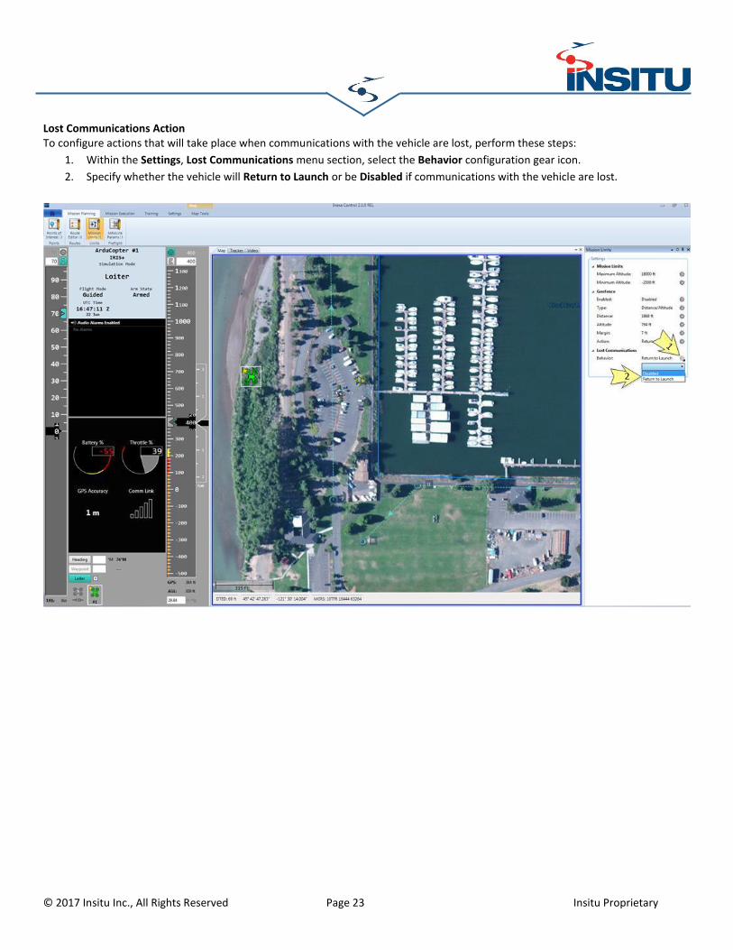
Lost Communications Action ................................................................................................................................... 23
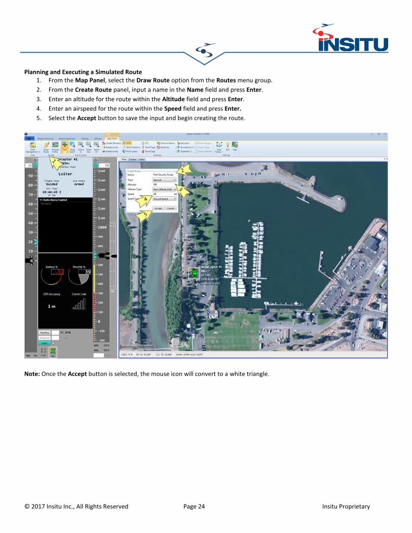
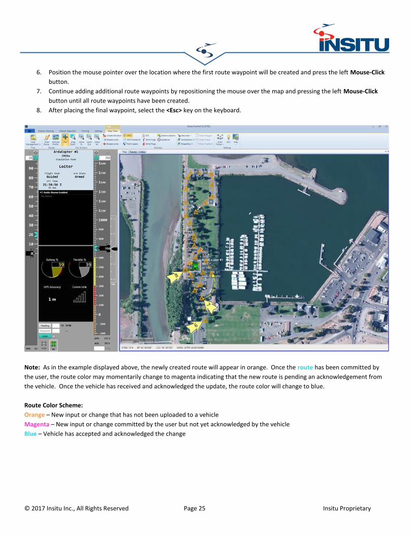
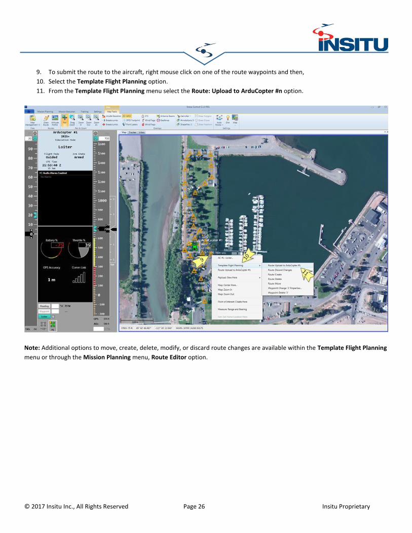
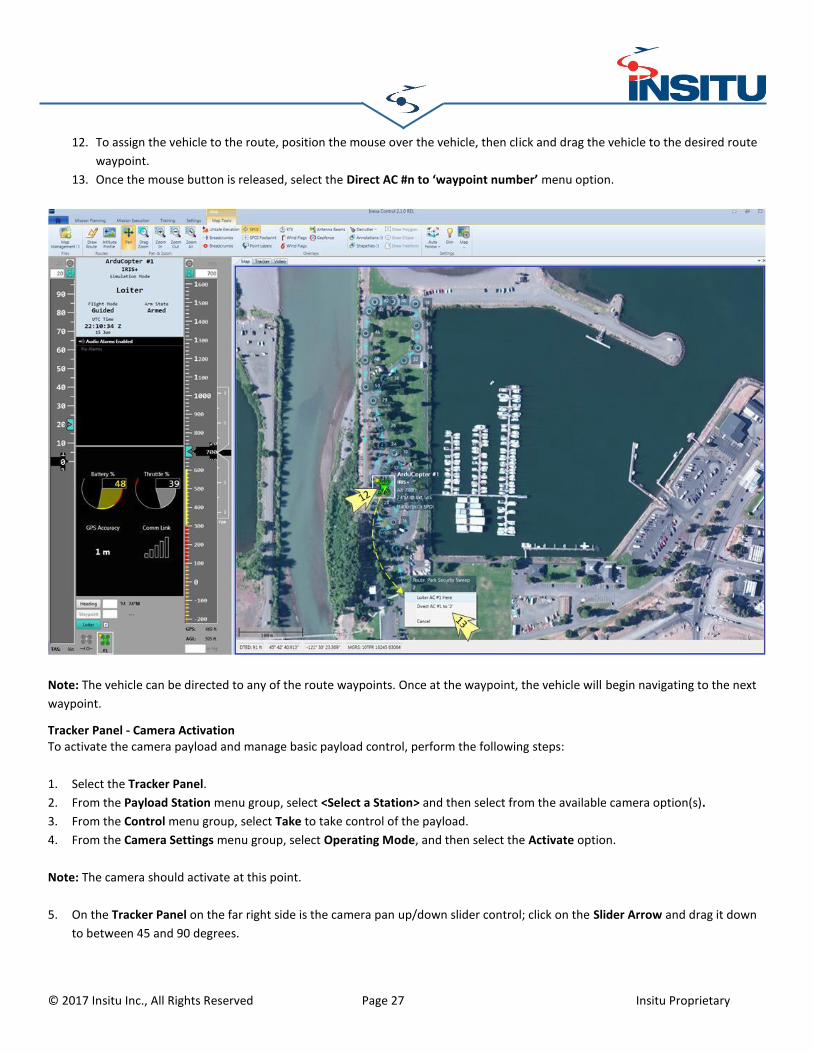
Planning and Executing a Simulated Route ............................................................................................................. 24
Tracker Panel - Camera Activation .......................................................................................................................... 27
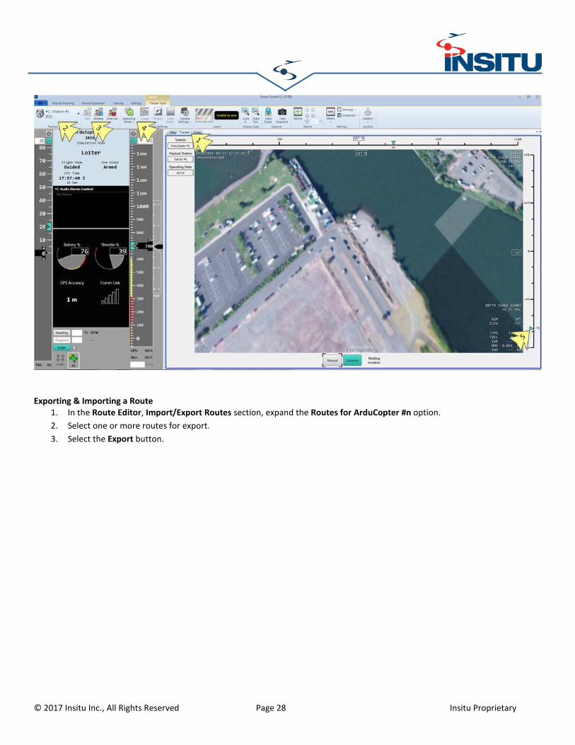
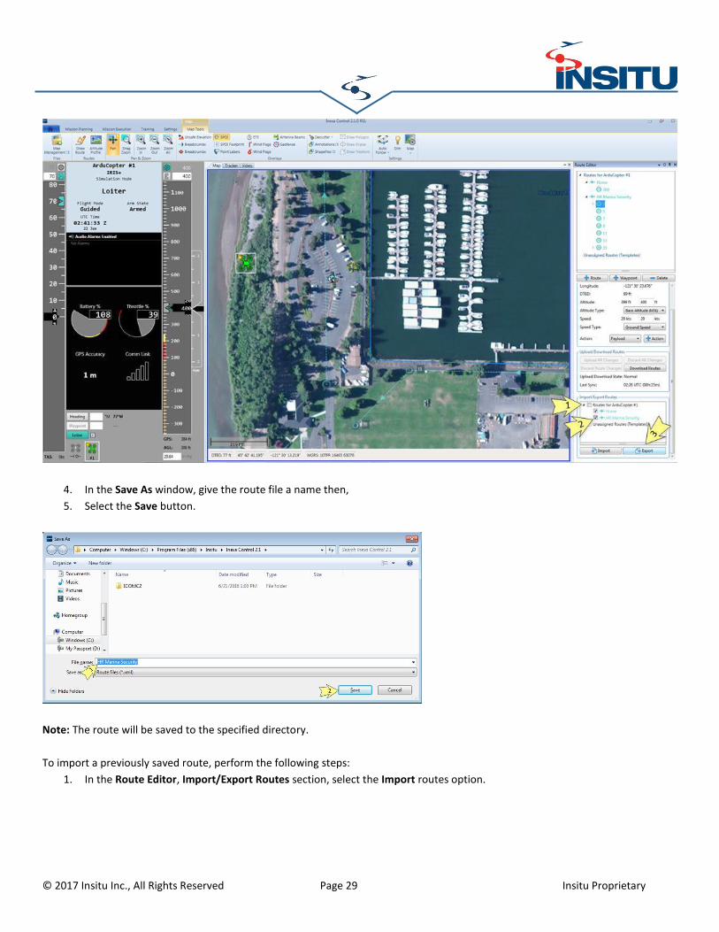
Exporting & Importing a Route ............................................................................................................................... 28
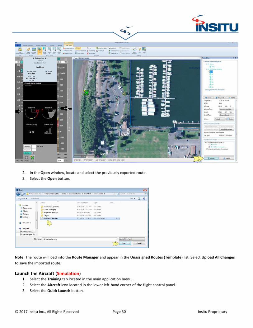
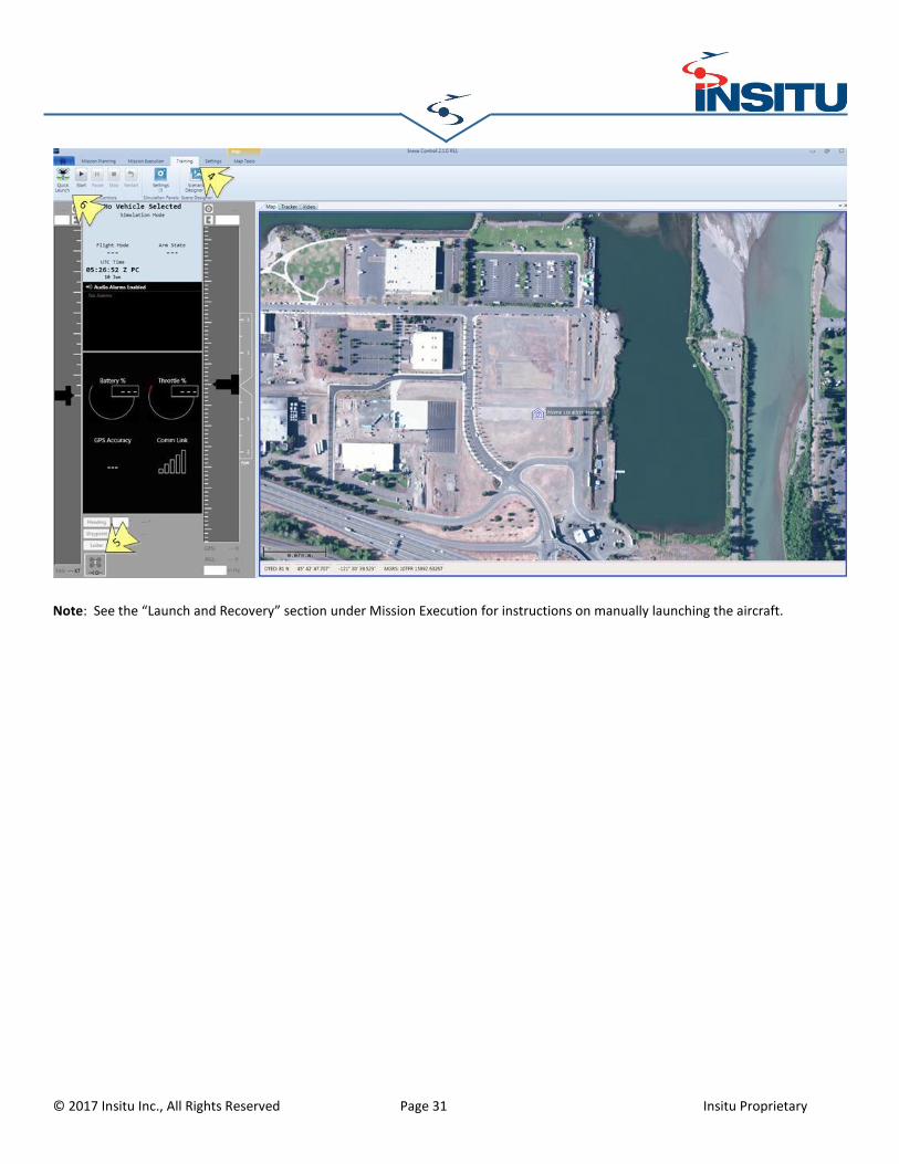
Launch the Aircraft (Simulation) ......................................................................................................................... 30
Launch the Aircraft (Physical ArduCopter).......................................................................................................... 32
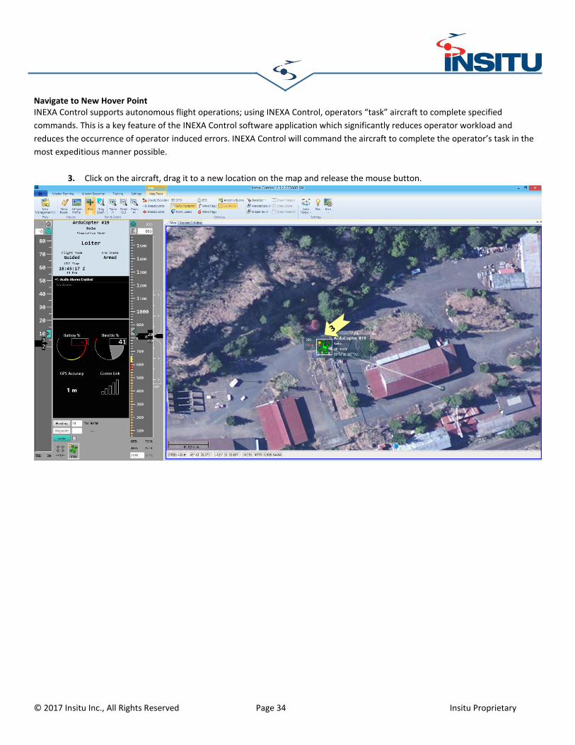
Navigate to New Hover Point ............................................................................................................................. 34
Export Compliance Notification INEXA™ Control, ArduCopter Plug-In, and ArduCopter Simulation are commercial software applications identified under Export Control Classification Number (ECCN) EAR99. No Export License is required for the export/re-export of these applications to non-US persons other than those from or in US Government imposed embargoed / sanctioned countries identified in the Supplement 1 to Part 740 (Country Group E) of the Export Administration Regulations (EAR). However, an export license is required for export/re-export to non-US persons from or in those embargoed / sanctioned countries. It is the responsibility of the individual in control of this related technical material to abide by the U.S. export laws. You acknowledge that the technical material is subject to U.S. export jurisdiction and that the technical material may only be exported from the United States in accordance with United States export laws. You also acknowledge that any diversion contrary to United States law is prohibited, and also agree to comply with all applicable non-U.S. export/import control laws that apply to the technical material. This includes end-user, end-use, and destination restrictions issued by the U.S. Government and other governments. You also agree not to export, re-export, import, transfer, or release the technical material to embargoed or sanctioned countries, in whole or in part to include:
(a) Into (or to a national resident of) any country to which the U.S. maintains embargoes or other restrictions,
(b) To any person on the US Treasury Department's list of Specially Designated nationals or,
(c) To any person or entity on the US Commerce Department's Denied Persons List, Entity List or Unverified List or, Table of Deny
Orders or,
(d) To any person or entity subject to a General Order 3 to Part 736 of the U.S. Commerce Department’s Export Administration
Regulations or,
(e) The U.S. Department of State’s Parties Subject to Nonproliferation Sanctions List or,
(f) To any person or entity or into any country where such export, re-export, or import violates any US, local, or other applicable
import/export control laws or regulations.
Version Notification A newer version of this document may be available on the Insitu product application site. You should always use the most current
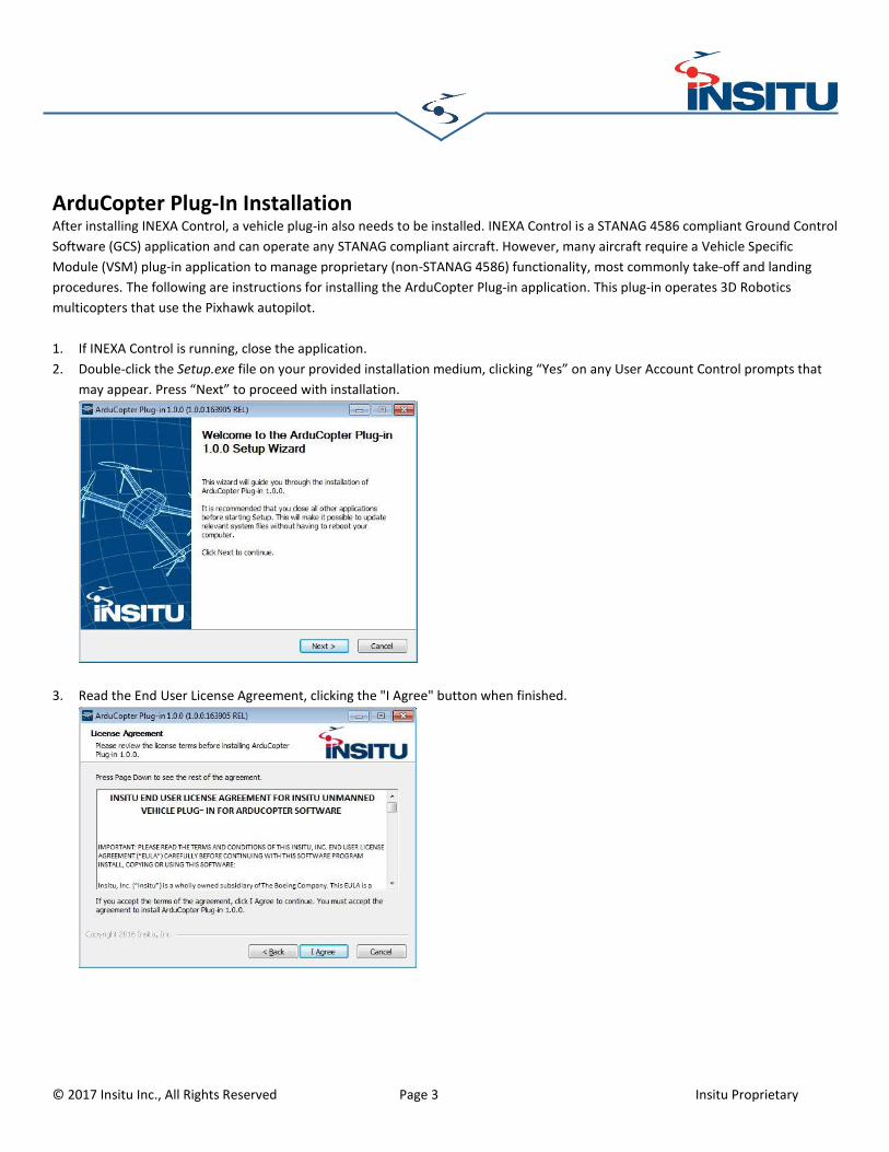
ArduCopter Plug-In Installation After installing INEXA Control, a vehicle plug-in also needs to be installed. INEXA Control is a STANAG 4586 compliant Ground Control
Software (GCS) application and can operate any STANAG compliant aircraft. However, many aircraft require a Vehicle Specific
Module (VSM) plug-in application to manage proprietary (non-STANAG 4586) functionality, most commonly take-off and landing
procedures. The following are instructions for installing the ArduCopter Plug-in application. This plug-in operates 3D Robotics
multicopters that use the Pixhawk autopilot.
1. If INEXA Control is running, close the application.
2. Double-click the Setup.exe file on your provided installation medium, clicking “Yes” on any User Account Control prompts that
may appear. Press “Next” to proceed with installation.
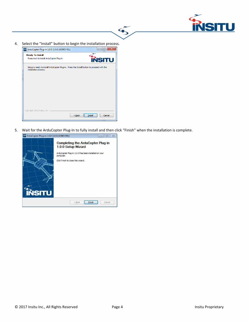
3. Read the End User License Agreement, clicking the "I Agree" button when finished.
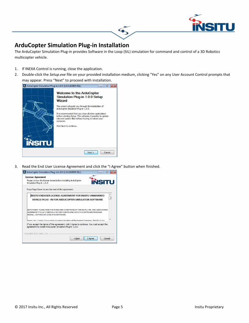
ArduCopter Simulation Plug-in Installation The ArduCopter Simulation Plug-in provides Software in the Loop (SIL) simulation for command and control of a 3D Robotics
multicopter vehicle.
1. If INEXA Control is running, close the application.
2. Double-click the Setup.exe file on your provided installation medium, clicking “Yes” on any User Account Control prompts that
may appear. Press “Next” to proceed with installation.
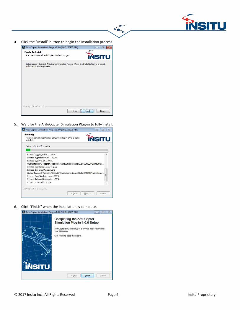
3. Read the End User License Agreement and click the “I Agree” button when finished.
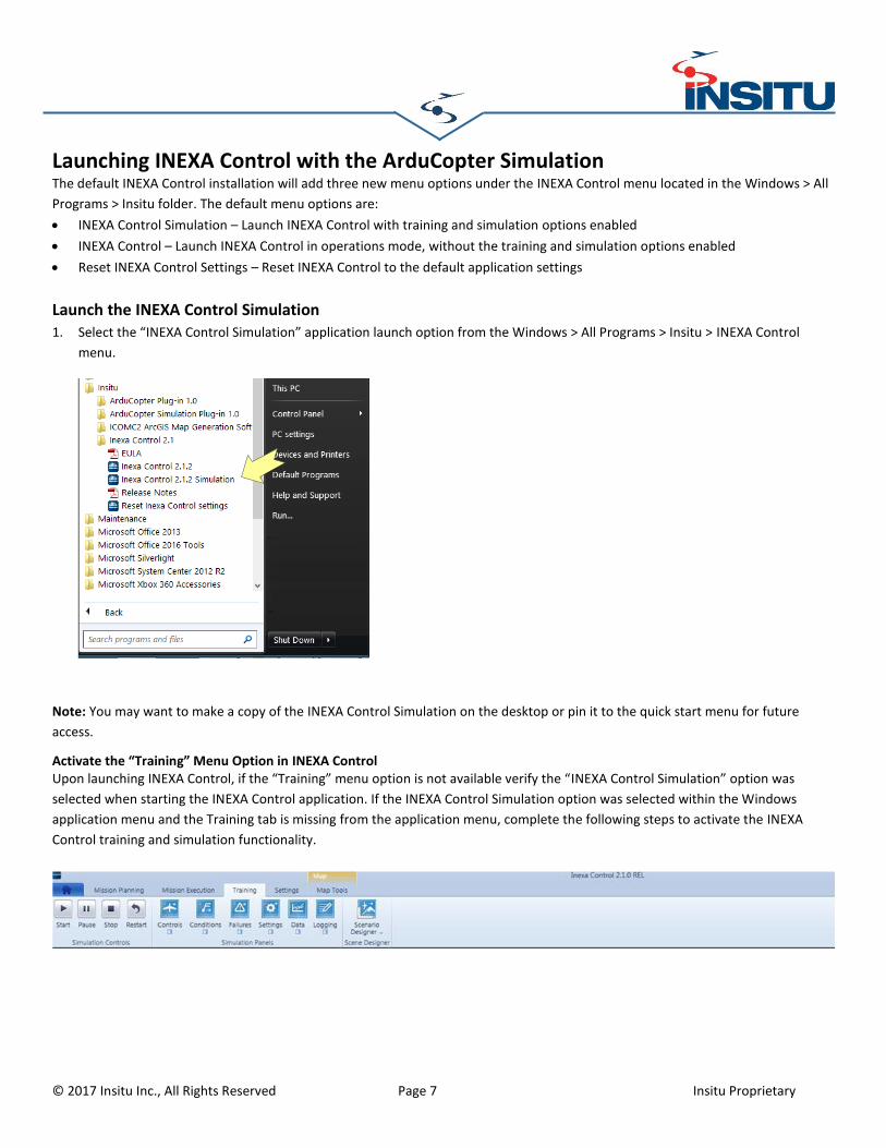
Launching INEXA Control with the ArduCopter Simulation The default INEXA Control installation will add three new menu options under the INEXA Control menu located in the Windows > All
Programs > Insitu folder. The default menu options are:
INEXA Control Simulation – Launch INEXA Control with training and simulation options enabled
INEXA Control – Launch INEXA Control in operations mode, without the training and simulation options enabled
Reset INEXA Control Settings – Reset INEXA Control to the default application settings
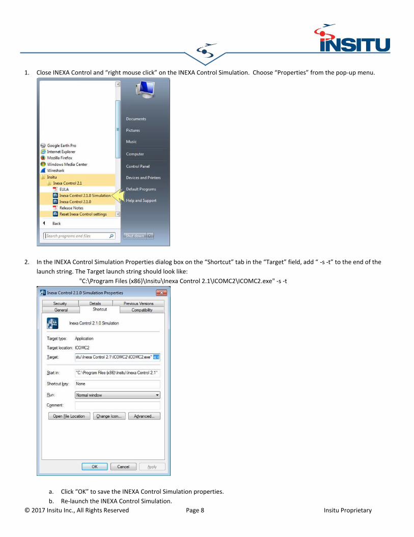
Launch the INEXA Control Simulation 1. Select the “INEXA Control Simulation” application launch option from the Windows > All Programs > Insitu > INEXA Control
menu.
Note: You may want to make a copy of the INEXA Control Simulation on the desktop or pin it to the quick start menu for future
access.
Activate the “Training” Menu Option in INEXA Control Upon launching INEXA Control, if the “Training” menu option is not available verify the “INEXA Control Simulation” option was
selected when starting the INEXA Control application. If the INEXA Control Simulation option was selected within the Windows
application menu and the Training tab is missing from the application menu, complete the following steps to activate the INEXA
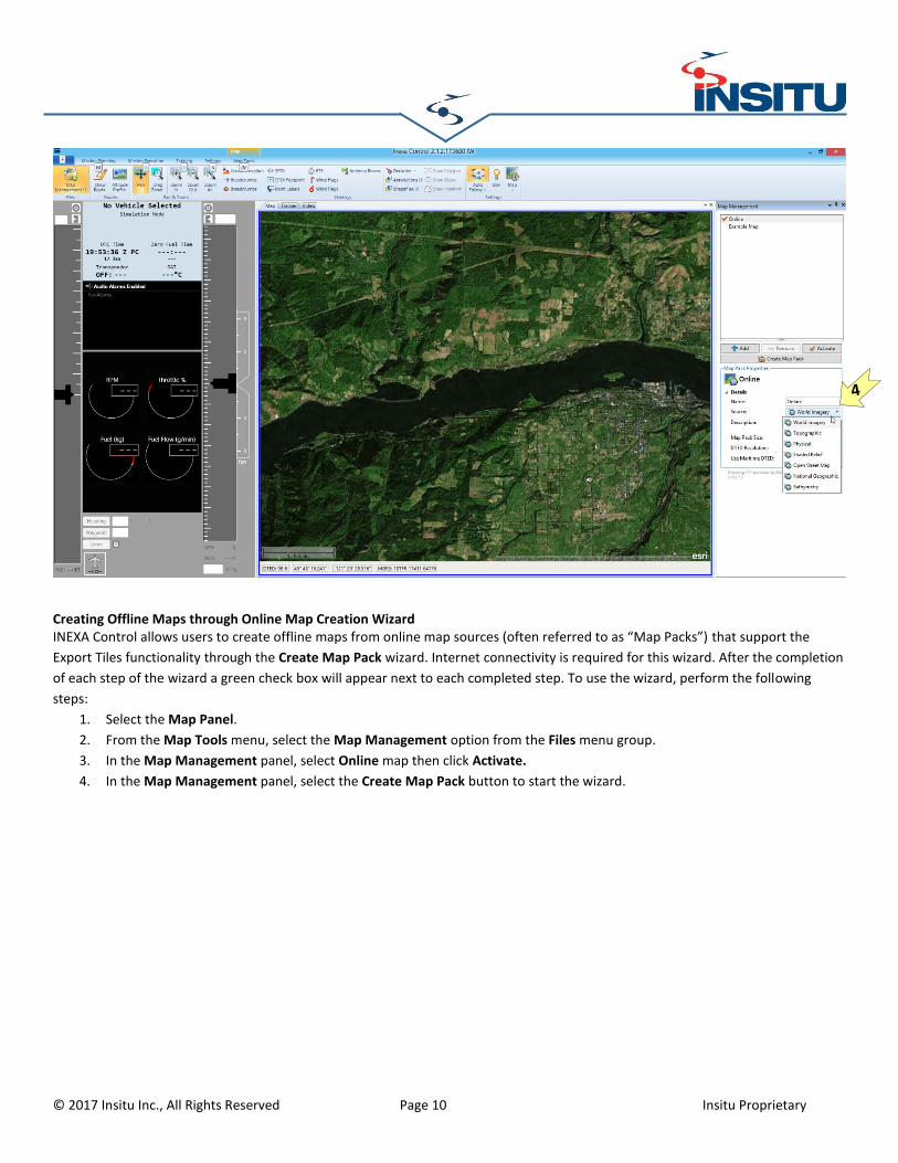
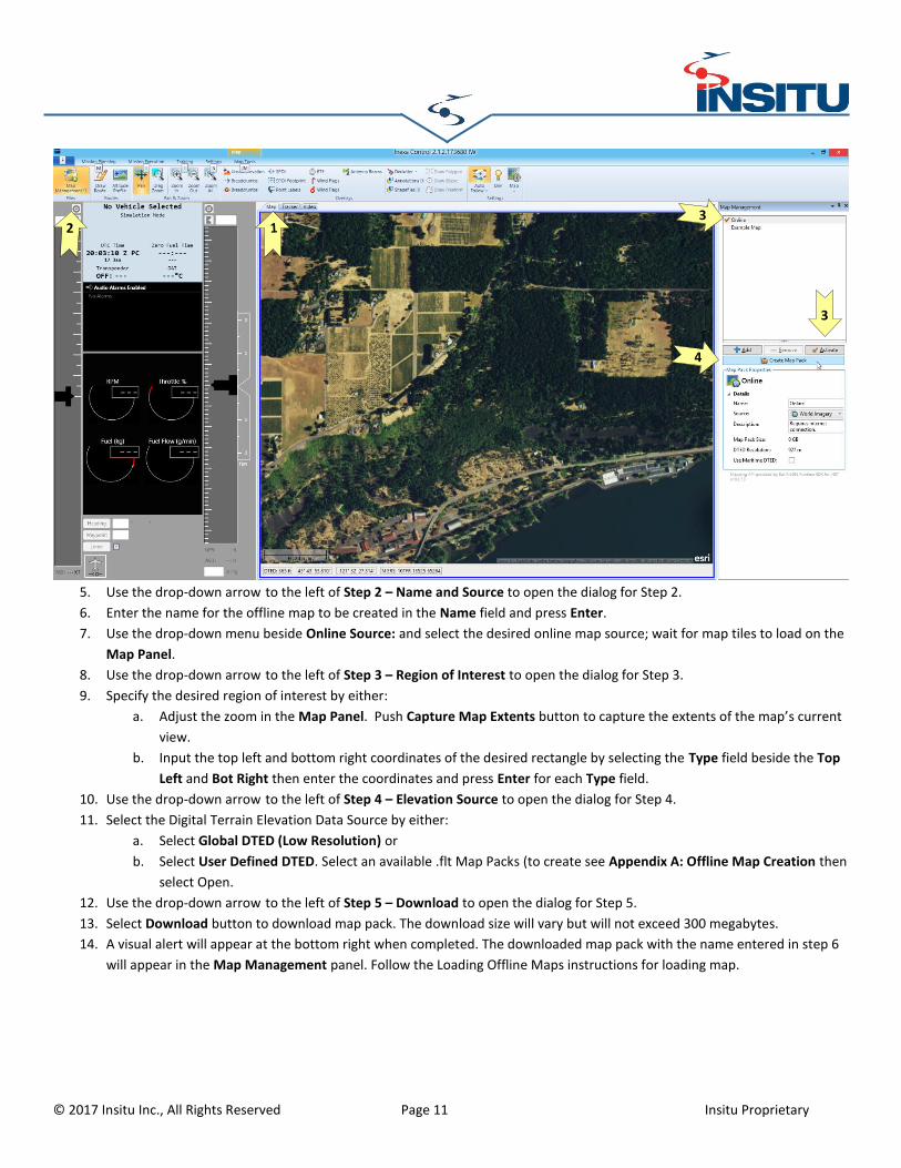
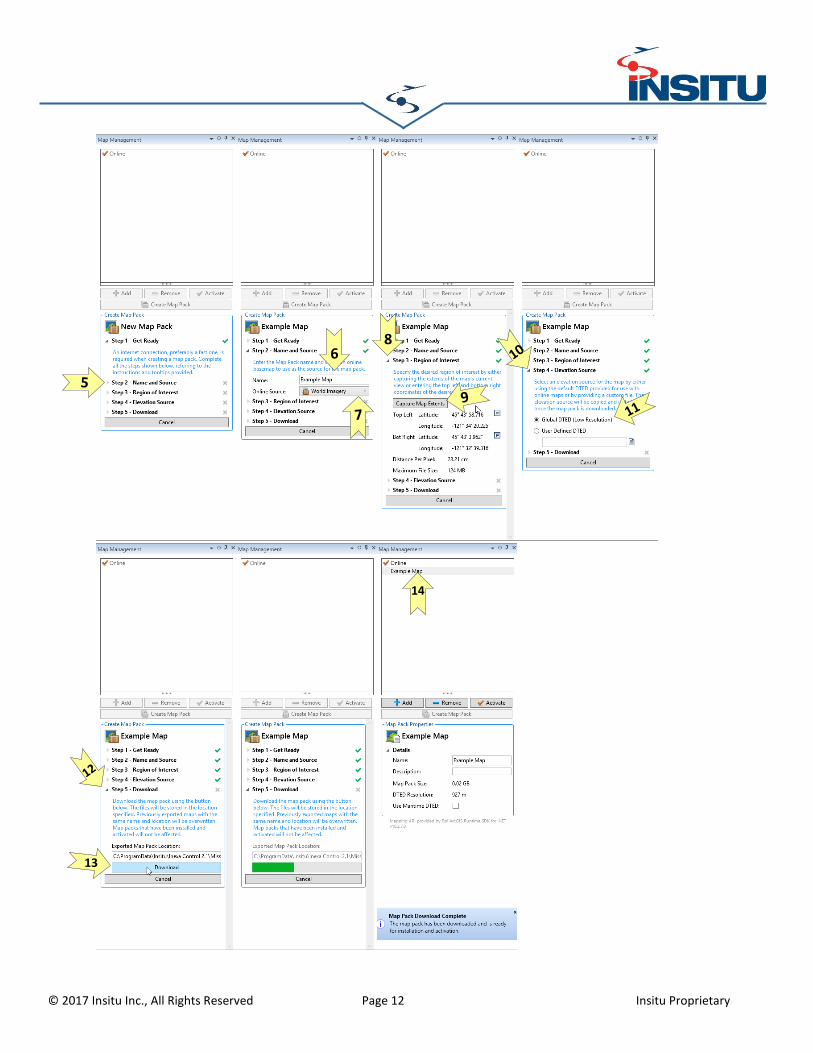
Creating Offline Maps through Online Map Creation Wizard INEXA Control allows users to create offline maps from online map sources (often referred to as “Map Packs”) that support the
Export Tiles functionality through the Create Map Pack wizard. Internet connectivity is required for this wizard. After the completion
of each step of the wizard a green check box will appear next to each completed step. To use the wizard, perform the following
steps:
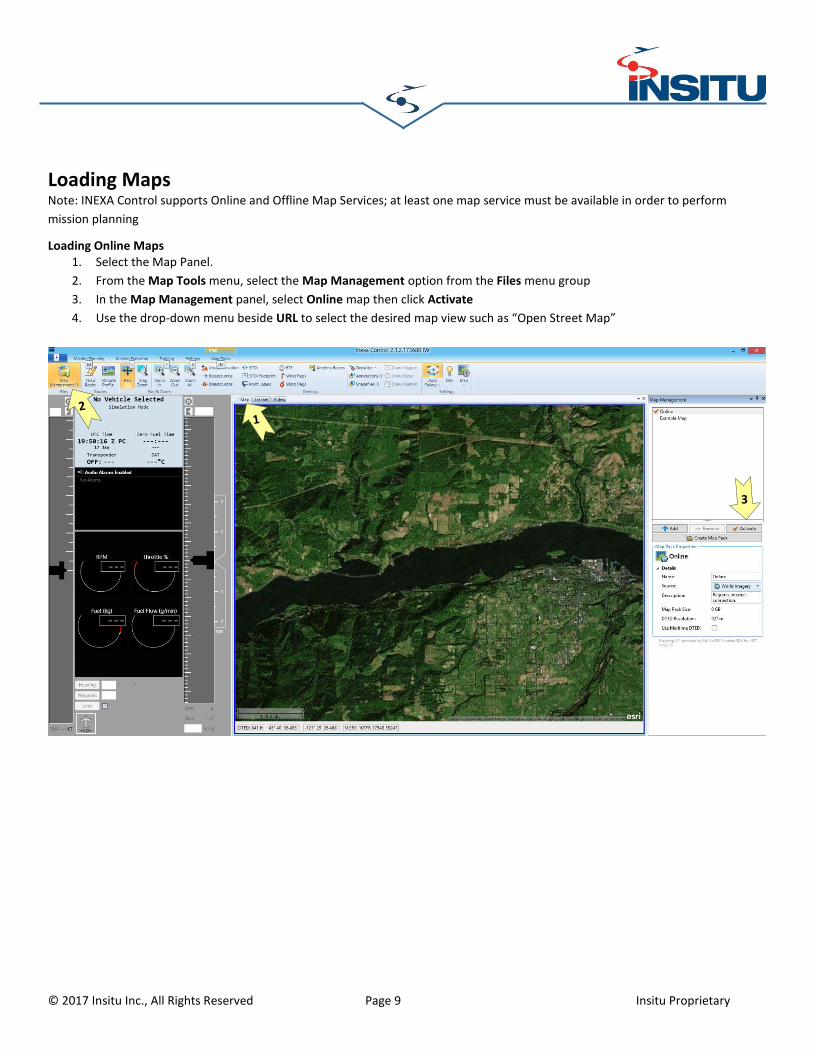
1. Select the Map Panel.
2. From the Map Tools menu, select the Map Management option from the Files menu group.
3. In the Map Management panel, select Online map then click Activate.
4. In the Map Management panel, select the Create Map Pack button to start the wizard.
Creating Offline Maps From 3rd Party Sources INEXA Control can use Offline Map Packs created through ESRI’s ArcGIS for desktop. Please refer to Appendix A: Offline Map
Creation located in the Operator’s Guide.
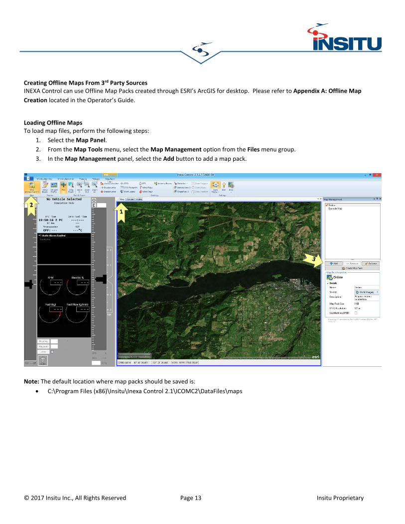
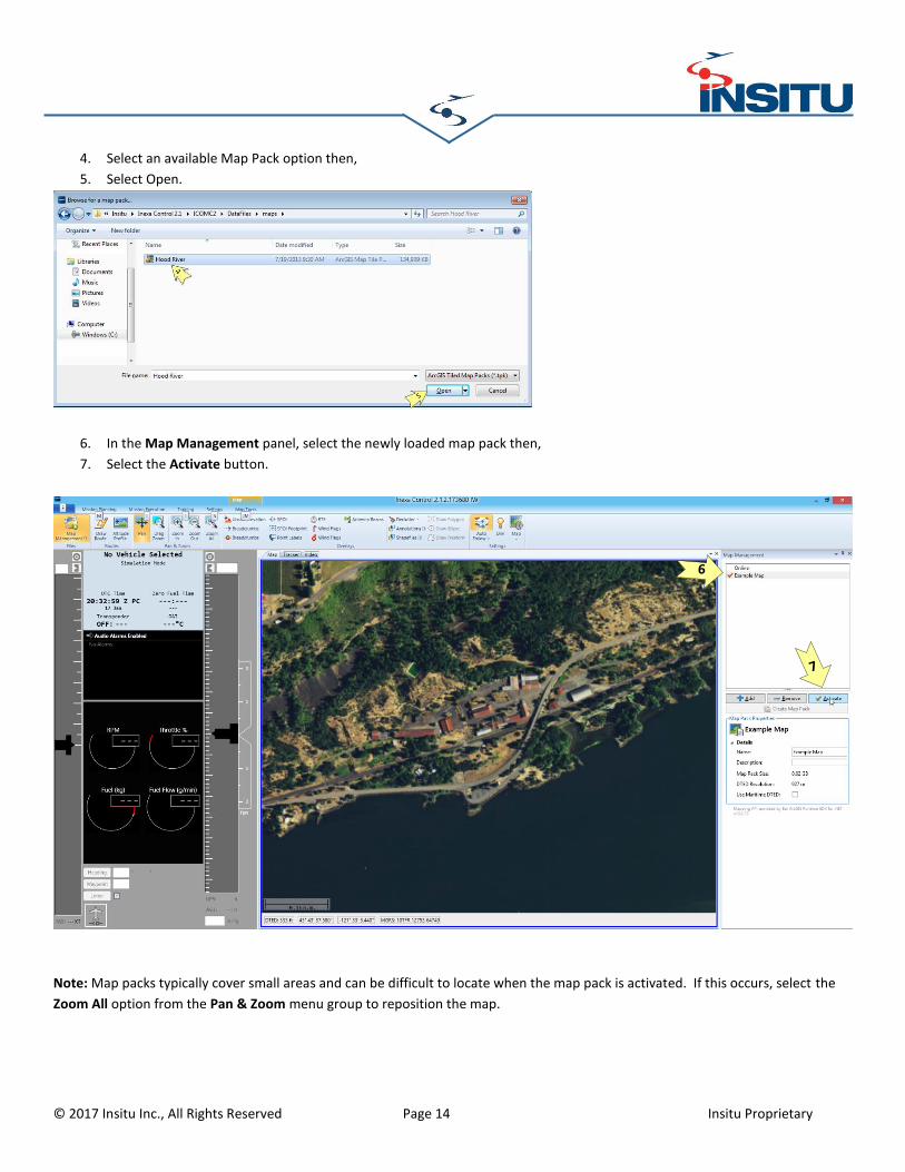
Loading Offline Maps To load map files, perform the following steps:
1. Select the Map Panel.
2. From the Map Tools menu, select the Map Management option from the Files menu group.
3. In the Map Management panel, select the Add button to add a map pack.
Note: The default location where map packs should be saved is:
C:\Program Files (x86)\Insitu\Inexa Control 2.1\ICOMC2\DataFiles\maps
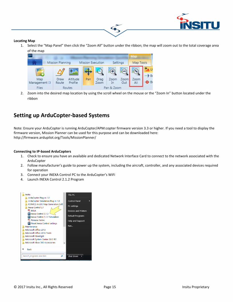
Locating Map 1. Select the “Map Panel” then click the “Zoom All” button under the ribbon; the map will zoom out to the total coverage area
of the map
2. Zoom into the desired map location by using the scroll wheel on the mouse or the “Zoom In” button located under the
ribbon
Setting up ArduCopter-based Systems
Note: Ensure your ArduCopter is running ArduCopter/APM:copter firmware version 3.3 or higher. If you need a tool to display the firmware version, Mission Planner can be used for this purpose and can be downloaded here: http://firmware.ardupilot.org/Tools/MissionPlanner/
Connecting to IP-based ArduCopters 1. Check to ensure you have an available and dedicated Network Interface Card to connect to the network associated with the
ArduCopter 2. Follow manufacturer’s guide to power up the system, including the aircraft, controller, and any associated devices required
for operation 3. Connect your INEXA Control PC to the ArduCopter’s WiFi 4. Launch INEXA Control 2.1.2 Program
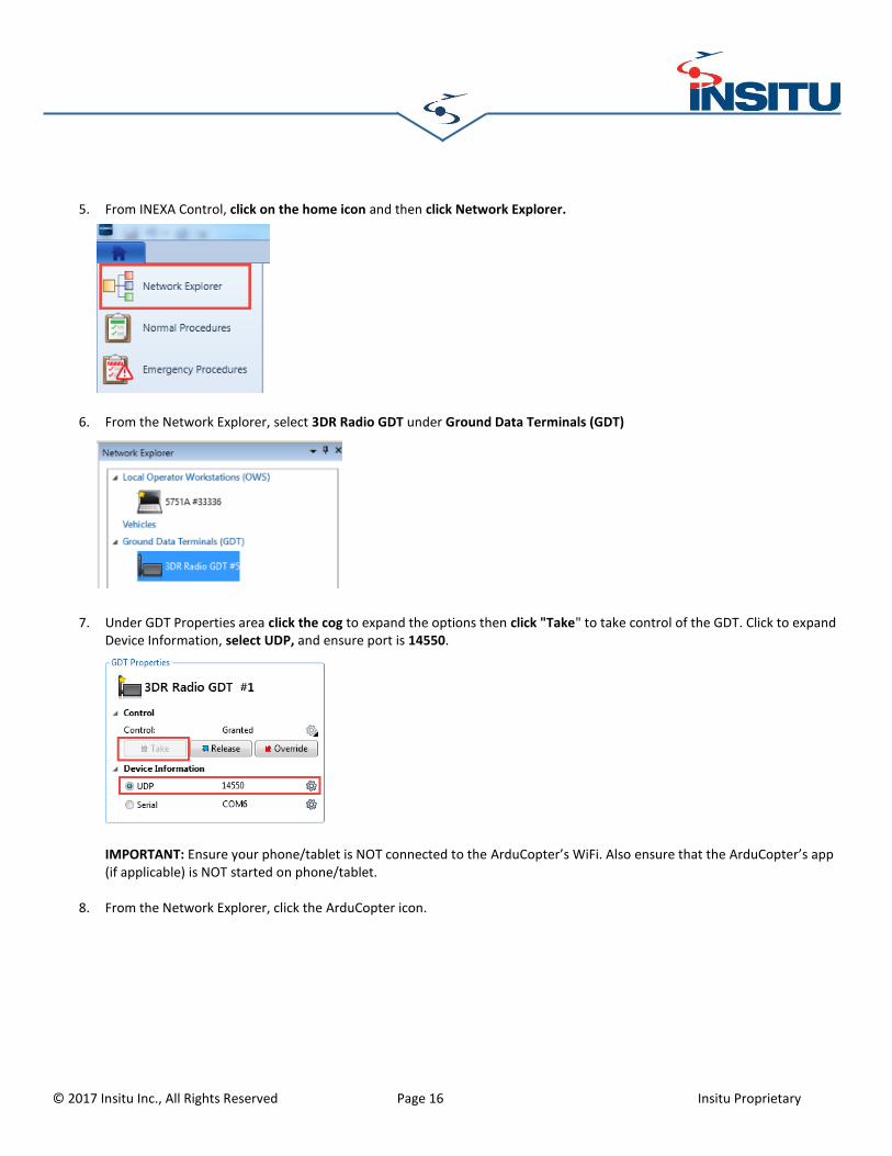
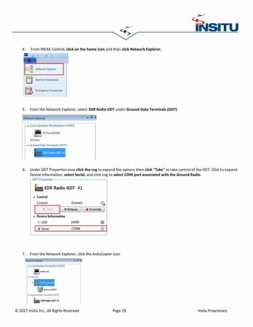
5. From INEXA Control, click on the home icon and then click Network Explorer.
6. From the Network Explorer, select 3DR Radio GDT under Ground Data Terminals (GDT)
7. Under GDT Properties area click the cog to expand the options then click "Take" to take control of the GDT. Click to expand Device Information, select UDP, and ensure port is 14550.
IMPORTANT: Ensure your phone/tablet is NOT connected to the ArduCopter’s WiFi. Also ensure that the ArduCopter’s app (if applicable) is NOT started on phone/tablet.
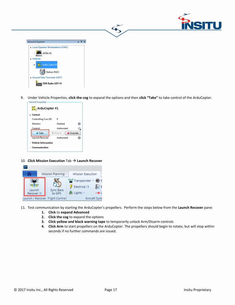
8. From the Network Explorer, click the ArduCopter icon.
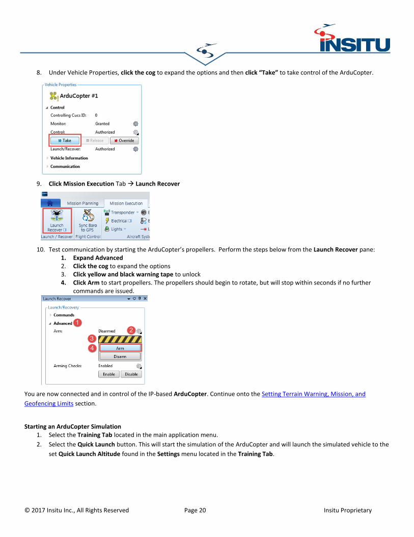
9. Under Vehicle Properties, click the cog to expand the options and then click “Take” to take control of the ArduCopter.
10. Click Mission Execution Tab Launch Recover
11. Test communication by starting the ArduCopter’s propellers. Perform the steps below from the Launch Recover pane:
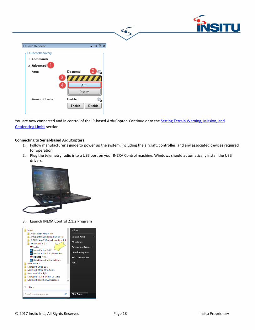
1. Click to expand Advanced 2. Click the cog to expand the options 3. Click yellow and black warning tape to temporarily unlock Arm/Disarm controls 4. Click Arm to start propellers on the ArduCopter. The propellers should begin to rotate, but will stop within
You are now connected and in control of the IP-based ArduCopter. Continue onto the Setting Terrain Warning, Mission, and
Geofencing Limits section.
Connecting to Serial-based ArduCopters 1. Follow manufacturer’s guide to power up the system, including the aircraft, controller, and any associated devices required
for operation 2. Plug the telemetry radio into a USB port on your INEXA Control machine. Windows should automatically install the USB
8. Under Vehicle Properties, click the cog to expand the options and then click “Take” to take control of the ArduCopter.
9. Click Mission Execution Tab Launch Recover
10. Test communication by starting the ArduCopter’s propellers. Perform the steps below from the Launch Recover pane: 1. Expand Advanced 2. Click the cog to expand the options 3. Click yellow and black warning tape to unlock 4. Click Arm to start propellers. The propellers should begin to rotate, but will stop within seconds if no further
commands are issued.
You are now connected and in control of the IP-based ArduCopter. Continue onto the Setting Terrain Warning, Mission, and
Geofencing Limits section.
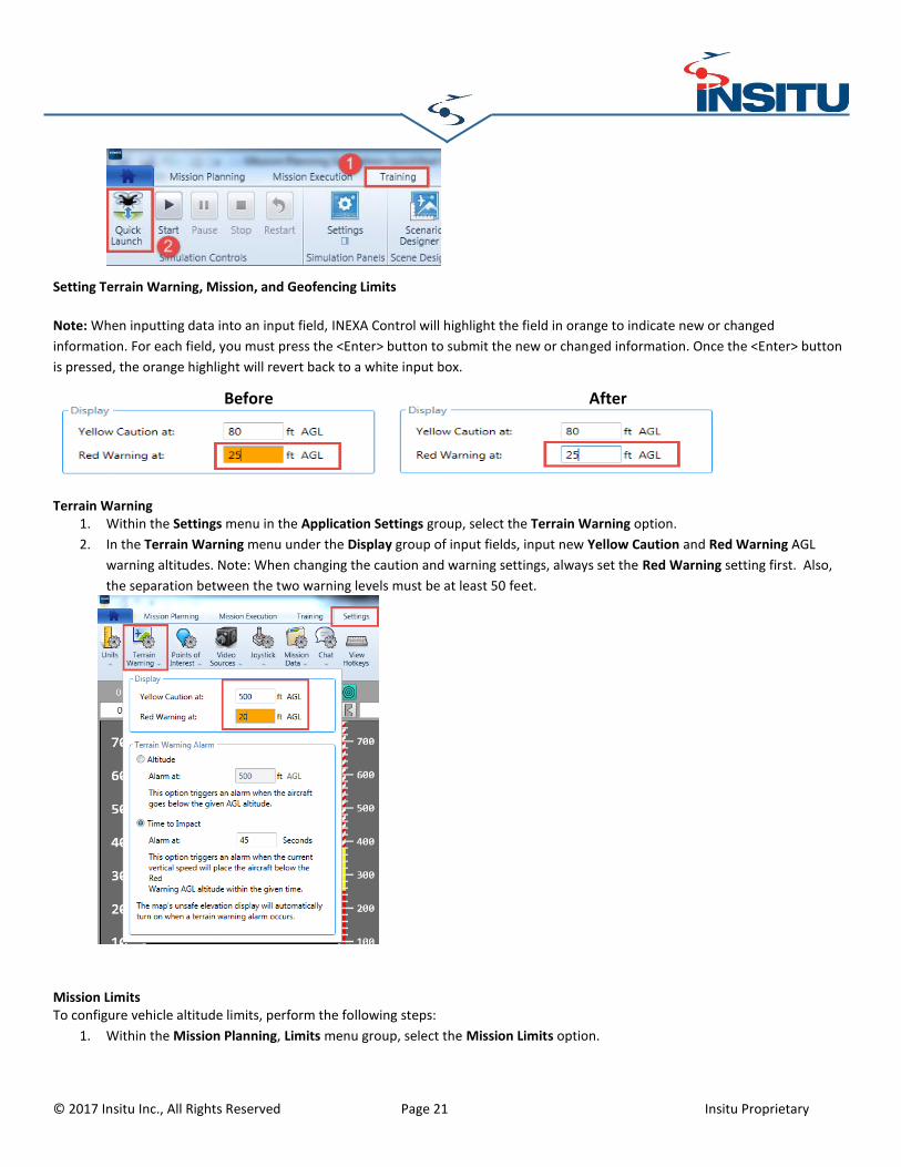
Starting an ArduCopter Simulation 1. Select the Training Tab located in the main application menu.
2. Select the Quick Launch button. This will start the simulation of the ArduCopter and will launch the simulated vehicle to the
set Quick Launch Altitude found in the Settings menu located in the Training Tab.
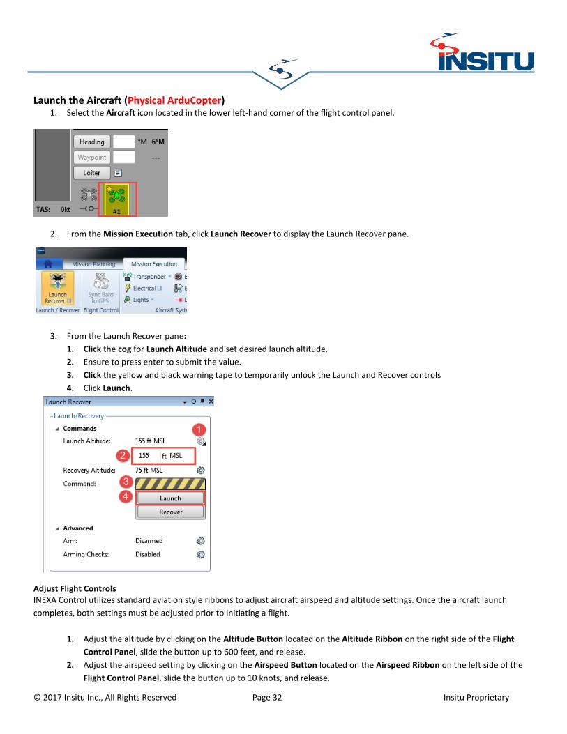
Launch the Aircraft (Physical ArduCopter) 1. Select the Aircraft icon located in the lower left-hand corner of the flight control panel.
2. From the Mission Execution tab, click Launch Recover to display the Launch Recover pane.
3. From the Launch Recover pane:
1. Click the cog for Launch Altitude and set desired launch altitude.
2. Ensure to press enter to submit the value.
3. Click the yellow and black warning tape to temporarily unlock the Launch and Recover controls
4. Click Launch.
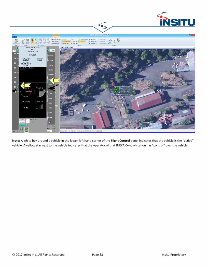
Adjust Flight Controls INEXA Control utilizes standard aviation style ribbons to adjust aircraft airspeed and altitude settings. Once the aircraft launch
completes, both settings must be adjusted prior to initiating a flight.
1. Adjust the altitude by clicking on the Altitude Button located on the Altitude Ribbon on the right side of the Flight
Control Panel, slide the button up to 600 feet, and release.
2. Adjust the airspeed setting by clicking on the Airspeed Button located on the Airspeed Ribbon on the left side of the
Flight Control Panel, slide the button up to 10 knots, and release.
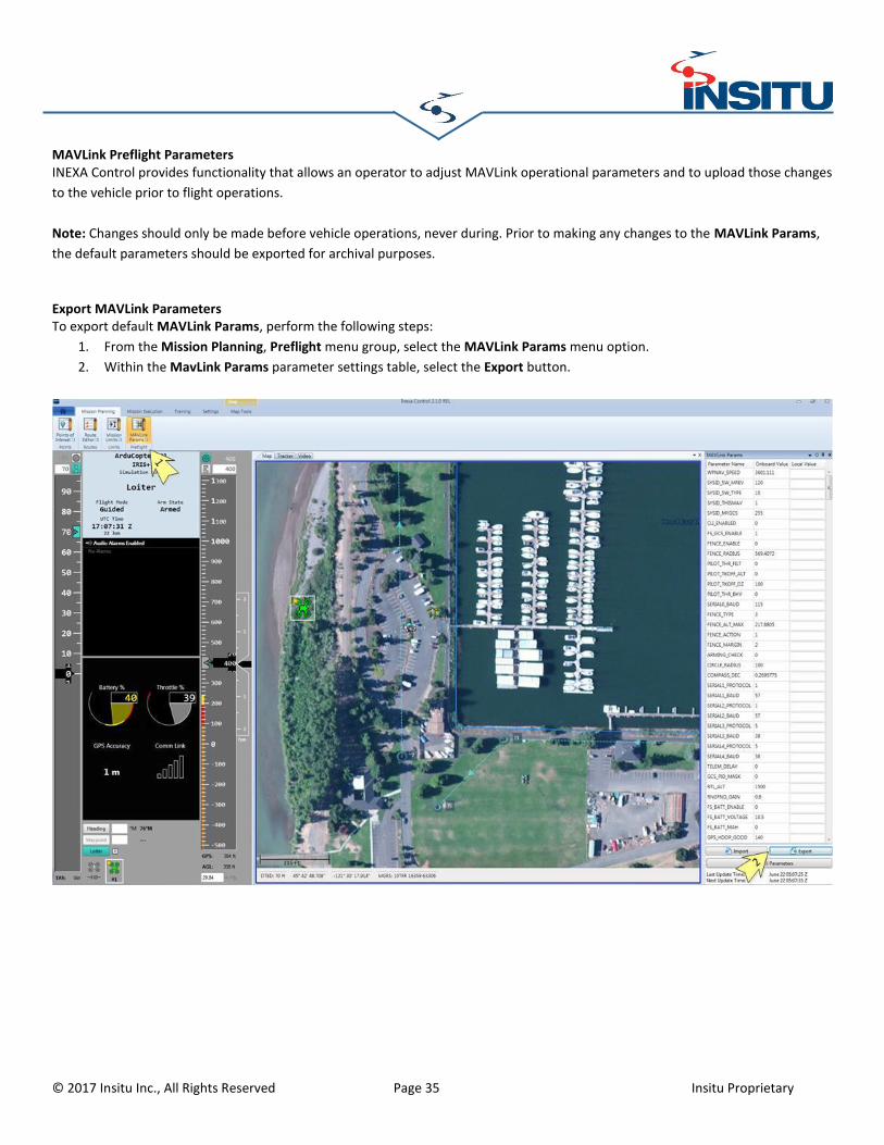
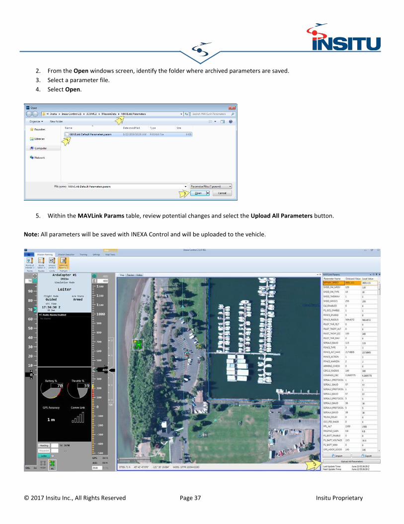
MAVLink Preflight Parameters INEXA Control provides functionality that allows an operator to adjust MAVLink operational parameters and to upload those changes
to the vehicle prior to flight operations.
Note: Changes should only be made before vehicle operations, never during. Prior to making any changes to the MAVLink Params,
the default parameters should be exported for archival purposes.
Export MAVLink Parameters To export default MAVLink Params, perform the following steps:
1. From the Mission Planning, Preflight menu group, select the MAVLink Params menu option.
2. Within the MavLink Params parameter settings table, select the Export button.