38
XBee Cookbook Issue 1.4 for Series 1 (Freescale) with 802.15.4 Firmware John Foster April 26, 2011

XBee Cookbook Issue 1.4 for Series 1 (Freescale) with 802.15.4Firmware
John Foster
April 26, 2011

2

Contents
1 Features 1-1
2 Electrical Specifications 2-12.1 Pinout . . . . . . . . . . . . . . . . . . . . . . . . . . . . . . . . . . . . . . . . . .. . . . . . . . . . 2-12.2 I/O Lines . . . . . . . . . . . . . . . . . . . . . . . . . . . . . . . . . . . . . . . .. . . . . . . . . . 2-1
2.2.1 All I/O Lines . . . . . . . . . . . . . . . . . . . . . . . . . . . . . . . . . . .. . . . . . . . . 2-12.2.2 All Inputs . . . . . . . . . . . . . . . . . . . . . . . . . . . . . . . . . . . . .. . . . . . . . . 2-22.2.3 Digital Inputs . . . . . . . . . . . . . . . . . . . . . . . . . . . . . . . . .. . . . . . . . . . . 2-32.2.4 Digital Outputs . . . . . . . . . . . . . . . . . . . . . . . . . . . . . . . .. . . . . . . . . . . 2-32.2.5 Analog Inputs and VREF . . . . . . . . . . . . . . . . . . . . . . . . . . .. . . . . . . . . . . 2-32.2.6 Analog Outputs . . . . . . . . . . . . . . . . . . . . . . . . . . . . . . . . .. . . . . . . . . . 2-32.2.7 I/O Line Passing . . . . . . . . . . . . . . . . . . . . . . . . . . . . . . . .. . . . . . . . . . 2-42.2.8 Serial Lines . . . . . . . . . . . . . . . . . . . . . . . . . . . . . . . . . . .. . . . . . . . . . 2-42.2.9 Pin 5 –RESET . . . . . . . . . . . . . . . . . . . . . . . . . . . . . . . . . . . . . . . . . . . 2-5
2.3 Voltage Level Conversions . . . . . . . . . . . . . . . . . . . . . . . . .. . . . . . . . . . . . . . . . 2-5
3 Operation 3-13.1 Version and Device Information . . . . . . . . . . . . . . . . . . . . .. . . . . . . . . . . . . . . . . 3-13.2 Module Mode . . . . . . . . . . . . . . . . . . . . . . . . . . . . . . . . . . . . . .. . . . . . . . . . 3-1
3.2.1 Transparent Mode . . . . . . . . . . . . . . . . . . . . . . . . . . . . . . .. . . . . . . . . . 3-13.2.2 API Mode . . . . . . . . . . . . . . . . . . . . . . . . . . . . . . . . . . . . . . .. . . . . . . 3-1
3.3 Module State . . . . . . . . . . . . . . . . . . . . . . . . . . . . . . . . . . . . .. . . . . . . . . . . 3-23.3.1 Idle State . . . . . . . . . . . . . . . . . . . . . . . . . . . . . . . . . . . . .. . . . . . . . . 3-23.3.2 Sleep State . . . . . . . . . . . . . . . . . . . . . . . . . . . . . . . . . . . .. . . . . . . . . 3-23.3.3 Command State . . . . . . . . . . . . . . . . . . . . . . . . . . . . . . . . . .. . . . . . . . . 3-2
3.4 Flow Control . . . . . . . . . . . . . . . . . . . . . . . . . . . . . . . . . . . . .. . . . . . . . . . . 3-33.4.1 Hardware Flow Control . . . . . . . . . . . . . . . . . . . . . . . . . . .. . . . . . . . . . . 3-33.4.2 Software Flow Control . . . . . . . . . . . . . . . . . . . . . . . . . . .. . . . . . . . . . . . 3-3
4 Networking 4-14.1 Network Types . . . . . . . . . . . . . . . . . . . . . . . . . . . . . . . . . . . .. . . . . . . . . . . 4-14.2 NonBeacon . . . . . . . . . . . . . . . . . . . . . . . . . . . . . . . . . . . . . . .. . . . . . . . . . 4-14.3 NonBeacon w/Coordinator . . . . . . . . . . . . . . . . . . . . . . . . . .. . . . . . . . . . . . . . . 4-14.4 Transmission Modes . . . . . . . . . . . . . . . . . . . . . . . . . . . . . . .. . . . . . . . . . . . . 4-14.5 Collision Avoidance . . . . . . . . . . . . . . . . . . . . . . . . . . . . . .. . . . . . . . . . . . . . . 4-14.6 MAC Mode . . . . . . . . . . . . . . . . . . . . . . . . . . . . . . . . . . . . . . . . .. . . . . . . . 4-24.7 Network Addressing . . . . . . . . . . . . . . . . . . . . . . . . . . . . . . .. . . . . . . . . . . . . 4-24.8 Network Identification and Scanning . . . . . . . . . . . . . . . . .. . . . . . . . . . . . . . . . . . . 4-24.9 Network Association . . . . . . . . . . . . . . . . . . . . . . . . . . . . . .. . . . . . . . . . . . . . 4-34.10 Encryption . . . . . . . . . . . . . . . . . . . . . . . . . . . . . . . . . . . . .. . . . . . . . . . . . . 4-34.11 Power Levels . . . . . . . . . . . . . . . . . . . . . . . . . . . . . . . . . . . .. . . . . . . . . . . . 4-3
5 API Packets 5-15.1 All Packets . . . . . . . . . . . . . . . . . . . . . . . . . . . . . . . . . . . . . .. . . . . . . . . . . 5-15.2 Modem Status Packet . . . . . . . . . . . . . . . . . . . . . . . . . . . . . . .. . . . . . . . . . . . . 5-15.3 Local AT Command Packets . . . . . . . . . . . . . . . . . . . . . . . . . . .. . . . . . . . . . . . . 5-2
i

ii CONTENTS
5.3.1 AT Command . . . . . . . . . . . . . . . . . . . . . . . . . . . . . . . . . . . . .. . . . . . . 5-25.3.2 AT Response . . . . . . . . . . . . . . . . . . . . . . . . . . . . . . . . . . . .. . . . . . . . 5-2
5.4 Remote AT Command Packets . . . . . . . . . . . . . . . . . . . . . . . . . .. . . . . . . . . . . . . 5-35.4.1 Remote AT Command . . . . . . . . . . . . . . . . . . . . . . . . . . . . . . .. . . . . . . . 5-35.4.2 Remote AT Response . . . . . . . . . . . . . . . . . . . . . . . . . . . . . .. . . . . . . . . . 5-3
5.5 Input Line States . . . . . . . . . . . . . . . . . . . . . . . . . . . . . . . . .. . . . . . . . . . . . . 5-45.6 Transmit Request . . . . . . . . . . . . . . . . . . . . . . . . . . . . . . . . .. . . . . . . . . . . . . 5-4
5.6.1 TX Request . . . . . . . . . . . . . . . . . . . . . . . . . . . . . . . . . . . . .. . . . . . . . 5-45.6.2 RX . . . . . . . . . . . . . . . . . . . . . . . . . . . . . . . . . . . . . . . . . . . .. . . . . 5-55.6.3 TX Status . . . . . . . . . . . . . . . . . . . . . . . . . . . . . . . . . . . . . .. . . . . . . . 5-5
A Baud Rates and their Accuracy A-1A.1 System Clock Frequency and UART Clock . . . . . . . . . . . . . . . .. . . . . . . . . . . . . . . . A-1A.2 Available Baud Rates . . . . . . . . . . . . . . . . . . . . . . . . . . . . . .. . . . . . . . . . . . . . A-1A.3 Serial Line Receiver Operation . . . . . . . . . . . . . . . . . . . . .. . . . . . . . . . . . . . . . . . A-2A.4 Signal Quality . . . . . . . . . . . . . . . . . . . . . . . . . . . . . . . . . . .. . . . . . . . . . . . . A-2A.5 Solution at 115,200 baud . . . . . . . . . . . . . . . . . . . . . . . . . . .. . . . . . . . . . . . . . . A-2A.6 Discussion of 57,600 Baud . . . . . . . . . . . . . . . . . . . . . . . . . .. . . . . . . . . . . . . . . A-3A.7 Baud Rate Accuracy on Other XBees . . . . . . . . . . . . . . . . . . . .. . . . . . . . . . . . . . . A-3A.8 Historical Note . . . . . . . . . . . . . . . . . . . . . . . . . . . . . . . . . .. . . . . . . . . . . . . A-3
B A Study of Custom Baud Rates on the Series 1 XBee B-1B.1 Introduction . . . . . . . . . . . . . . . . . . . . . . . . . . . . . . . . . . . .. . . . . . . . . . . . . B-1B.2 The Calculation of Percentages . . . . . . . . . . . . . . . . . . . . .. . . . . . . . . . . . . . . . . . B-1B.3 Standard Baud Rates . . . . . . . . . . . . . . . . . . . . . . . . . . . . . . .. . . . . . . . . . . . . B-2B.4 How Close do Baud Rates Need to Be? . . . . . . . . . . . . . . . . . . . .. . . . . . . . . . . . . . B-2
C Using X-CTU under Linux C-1
D Change Log D-1D.1 Changes . . . . . . . . . . . . . . . . . . . . . . . . . . . . . . . . . . . . . . . . .. . . . . . . . . . D-1
D.1.1 Changes in issue 1.4 (published 26 Apr 2011) . . . . . . . . .. . . . . . . . . . . . . . . . . . D-1D.1.2 Changes in issue 1.3 (published 9 Mar 2011) . . . . . . . . . .. . . . . . . . . . . . . . . . . D-1D.1.3 Changes in Issue 1.2 (published 7 Mar 2010) . . . . . . . . . .. . . . . . . . . . . . . . . . . D-1D.1.4 Changes in Issue 1.1 (published 26 Jan 2010) . . . . . . . . .. . . . . . . . . . . . . . . . . . D-2D.1.5 Issue 1.0 . . . . . . . . . . . . . . . . . . . . . . . . . . . . . . . . . . . . . .. . . . . . . . D-2
Index 1

Chapter 1
Features
The XBee and XBee Pro are plug-in replacements for each other. The difference between them is that the XBee Prooperates at higher power and has a more sensitive receiver. Table 1.1 shows the relevant figures. Note that in Europe theoutput power of the XBee Pro must be restricted to 10dBm. The current of 137mA corresponds to that level.
In each case, the RF data rate is 250Kbps and the serial I/O rate is selectable between 1200 and 115200 baud.
Item XBee XBee ProRange, indoor/urban 30m 100mRange, outdoor/line of sight 100m 1 mileTransmit power 1mW 100mWReceiver sensitivity -92dBm -100dBmTX current (@3.3V) 45mA 137mARX current (@3.3V) 50mA 55mAPower-down current < 10µA < 10µASequence channels 16 12
Table 1.1: Differences between XBee and XBee Pro.
1-1

1-2 CHAPTER 1. FEATURES

Chapter 2
Electrical Specifications
2.1 Pinout
If the XBee is viewed from the top and with the bevelled end facing north, then pins 1 to 10 run down the west side fromnorth to south, and pins 11 to 20 run up the east side from southto north. Table 2.1 shows the pinout. Pins that are notused should be left disconnected.
2.2 I/O Lines
2.2.1 All I/O Lines
Eight of the I/O lines are fitted with pull-up resistors whichcan be enabled or disabled with thePR parameter. This isan 8-bit mask, where a 0 disables the pull-up and a 1 enables it. Table 2.1 gives the bit positions in the column labelledPR. The default value is 0xff.
I/O pins are configured using theDn parameter. The command is followed by the pin code from the AT column ofTable 2.1, and the command assigns a mode code which is 0 to disable the line, 1 to enable the line’s special function (seenext para), 2 for analog input, 3 for digital input, 4 for digital output low and 5 for digital output high. For example, thecommand to set AD1/DIO1 (pin 19) as an analog input would be ATD1=2.
I/O lines with special functions have those functions enabled by setting theirDn parameter to 1. These lines are line7 (CTS), 6 (RTS) and 5 (Associated indicator). For lines 7 and5, this is the default state. For line 6, the default state isdisabled. Changes made via the Dn parameter become effective the next time an AC command is issued.
Under firmware version 1084, any attempt to read the Dn parameter for0 ≤ n ≤ 4 just got an “ERROR” return. Fromversion 10C8 the response is as it should be.
The Associated indicator output will blink a LED while the module is associated.To disable any I/O line, set its Dn parameter to 0.
I/O Data Packet
TheIS parameter forces a read of all enabled inputs and outputs (analog or digital) with the data being returned throughthe UART. If no inputs are enabled, the command returns “ERROR”. The IS command can take a parameter, with a valuein the range 1 to 0xff and a default value of 1. The product manual is silent on the question of what the parameter isfor, but when I asked Digi they replied that the parameter hasno purpose and should be removed in a future firmwarerelease. Under firmware version 10C8 an attempt to read the ISparameter will return “ERROR” unless at least one lineis configured as a digital or analog input. In API mode, the data will be returned as a pair of packets. The first will be astatus return, and presumably an error status means the second packet won’t be present. The second packet is an I/O datapacket.
An I/O data packet is also sent when theIC parameter has any bits set. This parameter enables change detectionon DIO lines 7 to 0 when the corresponding bits are 1. Any change on any enabled line first causes transmission of anyqueued data, and then causes the DIO data to be transmitted. The default value for the IC parameter is 0x00. This packetwill report only digital line states.
A module receiving a packet sent because of the IC parameter will respond in one of two ways:
2-1

2-2 CHAPTER 2. ELECTRICAL SPECIFICATIONS
Pin Name Direction Description AT PR1 VCC – Power supply2 DOUT Output UART data out3 DIN / CONFIG Input UART data in 74 DO8 Output Digital output 85 RESET Input Module reset (at least 200nS)6 PWM0 / RSSI Output PWM output 0 / RX signal strength indicator7 PWM1 Output PWM output 18 (reserved) Do not connect9 DTR / SLEEPRQ / DI8 Input Pin sleep control line or digital input 8 D8 610 GND – Ground11 AD4 / DIO4 Either Analog input 4 or digital I/O 4 D4 012 CTS / DIO7 Either Clear to send flow control or digital I/O 7 D713 ON / SLEEP Output Module status indicator14 VREF Input Voltage reference for AD inputs15 Associate / AD5 / DIO5 Either Associated indicator, analog input 5 or digital I/O 5D516 RTS / AD6 / DIO6 Either RTS flow control, analog input 6 or digital I/O 6 D6 517 AD3 / DIO3 Either Analog input 3 or digital I/O 3 D3 118 AD2 / DIO2 Either Analog input 2 or digital I/O 2 D2 219 AD1 / DIO1 Either Analog input 1 or digital I/O 1 D1 320 AD0 / DIO0 Either Analog input 0 or digital I/O 0 D0 4
Table 2.1: Pinout for XBee and XBee Pro. The AT column gives the tail of the Dn command for configuring the pin, andthe PR column gives the bit number in the PR command for configuring the pull-up resistor (see section 2.2.1). A note inthe 1xAx product manual says that pin 4 (DO8) is unsupported,and the 1xEx product manual says the same.
1. If the receiving module’sIA parameter is set to enable control by the sending module by holding the sendingmodule’s address or by holding the “accept all” value, then it will update its own I/O wires from the data in thepacket.
2. If the receiving module is not set to update its outputs, then the I/O packet is transmitted through the receivingmodule’s UART.
When an IO Data Packet is sent in transparent mode, all bytes are first converted to ASCII. Then the values arereported, each terminated by a carriage return. The order is:
1. The number of sample sets to follow. Items 2 to 4 in this listconstitute one sample set.
2. The channel indicator with a bit set for each enabled inputor output. This is a 16-bit word, with the most significantbyte sent first. In the high byte, bit 7 is not used and bits 6 to 1are set if the data will include samples from ADC5to ADC0 respectively. Bit 0 of the high byte is set if the data will include the state of line D8. In the low byte, bits7 to 0 correspond to lines DIO7 to DIO0.
3. The DIO data (line state) for each enabled digital input oroutput, if there are any enabled digital inputs or outputs.This is a 16-bit quantity, with the D8 state in bit 0 of the msb and bits 7–0 in the lsb.
4. The ADC data for each enabled analog input, in ascending order of line number. Each is an unsigned 16-bit quantity,with the 10-bit value in the low-order 10 bits.
5. The data is terminated by an extra carriage return.
2.2.2 All Inputs
The IR parameter sets or reads the sample rate. When set to a value other than 0, the module will sample all enabledinputs at time intervals given by the parameter value. The time unit is mS, and the maximum value is 0xffff. The default is0. A note in the Digi product manual says that sampling at a rate of more than one sample per 20mS is not recommended.
The IT parameter sets or reads how many samples (max) will be transmitted per packet. Its value is in the range 1to 0xff, with 1 as the default. When sleep modes are enabled anda sample rate (IR) is set, the module will remain awakeuntil IT samples have been collected.
2.2. I/O LINES 2-3
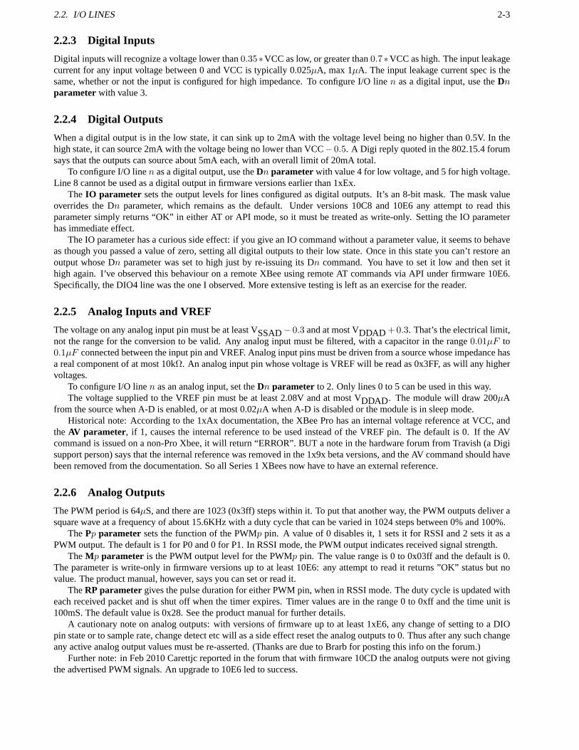
2.2.3 Digital Inputs
Digital inputs will recognize a voltage lower than0.35∗VCC as low, or greater than0.7∗VCC as high. The input leakagecurrent for any input voltage between 0 and VCC is typically 0.025µA, max 1µA. The input leakage current spec is thesame, whether or not the input is configured for high impedance. To configure I/O linen as a digital input, use theDnparameter with value 3.
2.2.4 Digital Outputs
When a digital output is in the low state, it can sink up to 2mA with the voltage level being no higher than 0.5V. In thehigh state, it can source 2mA with the voltage being no lower than VCC− 0.5. A Digi reply quoted in the 802.15.4 forumsays that the outputs can source about 5mA each, with an overall limit of 20mA total.
To configure I/O linen as a digital output, use theDn parameter with value 4 for low voltage, and 5 for high voltage.Line 8 cannot be used as a digital output in firmware versions earlier than 1xEx.
The IO parameter sets the output levels for lines configured as digital outputs. It’s an 8-bit mask. The mask valueoverrides the Dn parameter, which remains as the default. Under versions 10C8 and 10E6 any attempt to read thisparameter simply returns “OK” in either AT or API mode, so it must be treated as write-only. Setting the IO parameterhas immediate effect.
The IO parameter has a curious side effect: if you give an IO command without a parameter value, it seems to behaveas though you passed a value of zero, setting all digital outputs to their low state. Once in this state you can’t restore anoutput whose Dn parameter was set to high just by re-issuing its Dn command. You have to set it low and then set ithigh again. I’ve observed this behaviour on a remote XBee using remote AT commands via API under firmware 10E6.Specifically, the DIO4 line was the one I observed. More extensive testing is left as an exercise for the reader.
2.2.5 Analog Inputs and VREF
The voltage on any analog input pin must be at least VSSAD− 0.3 and at most VDDAD +0.3. That’s the electrical limit,not the range for the conversion to be valid. Any analog inputmust be filtered, with a capacitor in the range0.01µF to0.1µF connected between the input pin and VREF. Analog input pins must be driven from a source whose impedance hasa real component of at most 10kΩ. An analog input pin whose voltage is VREF will be read as 0x3FF, as will any highervoltages.
To configure I/O linen as an analog input, set theDn parameter to 2. Only lines 0 to 5 can be used in this way.The voltage supplied to the VREF pin must be at least 2.08V andat most VDDAD. The module will draw 200µA
from the source when A-D is enabled, or at most 0.02µA when A-D is disabled or the module is in sleep mode.Historical note: According to the 1xAx documentation, the XBee Pro has an internal voltage reference at VCC, and
the AV parameter, if 1, causes the internal reference to be used instead of theVREF pin. The default is 0. If the AVcommand is issued on a non-Pro Xbee, it will return “ERROR”. BUT a note in the hardware forum from Travish (a Digisupport person) says that the internal reference was removed in the 1x9x beta versions, and the AV command should havebeen removed from the documentation. So all Series 1 XBees now have to have an external reference.
2.2.6 Analog Outputs
The PWM period is 64µS, and there are 1023 (0x3ff) steps within it. To put that another way, the PWM outputs deliver asquare wave at a frequency of about 15.6KHz with a duty cycle that can be varied in 1024 steps between 0% and 100%.
ThePp parameter sets the function of the PWMp pin. A value of 0 disables it, 1 sets it for RSSI and 2 sets it as aPWM output. The default is 1 for P0 and 0 for P1. In RSSI mode, thePWM output indicates received signal strength.
TheMp parameter is the PWM output level for the PWMp pin. The value range is 0 to 0x03ff and the default is 0.The parameter is write-only in firmware versions up to at least 10E6: any attempt to read it returns ”OK” status but novalue. The product manual, however, says you can set or read it.
TheRP parametergives the pulse duration for either PWM pin, when in RSSI mode.The duty cycle is updated witheach received packet and is shut off when the timer expires. Timer values are in the range 0 to 0xff and the time unit is100mS. The default value is 0x28. See the product manual for further details.
A cautionary note on analog outputs: with versions of firmware up to at least 1xE6, any change of setting to a DIOpin state or to sample rate, change detect etc will as a side effect reset the analog outputs to 0. Thus after any such changeany active analog output values must be re-asserted. (Thanks are due to Brarb for posting this info on the forum.)
Further note: in Feb 2010 Carettjc reported in the forum thatwith firmware 10CD the analog outputs were not givingthe advertised PWM signals. An upgrade to 10E6 led to success.
2-4 CHAPTER 2. ELECTRICAL SPECIFICATIONS
463f 464aIR 5 secs IA 0xffffIT 1DH 0DL 0x1234 MY 0x1234D0 outputD1 input D1 outputIC 0x02 T1 2 secs
Table 2.2: I/O line passing between two XBees, using periodic sampling. The top line shows the last four hex digits oftheir serial numbers. The one on the left is passing its DIO1 input to the one on the right. On the left, output DIO0 iswired to input DIO1.
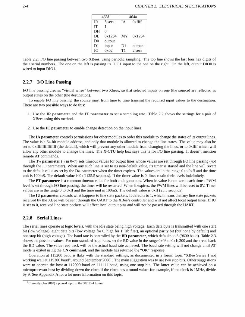
2.2.7 I/O Line Passing
I/O line passing creates “virtual wires” between two Xbees,so that selected inputs on one (the source) are reflected asoutput states on the other (the destination).
To enable I/O line passing, the source must from time to time transmit the required input values to the destination.There are two possible ways to do this:
1. Use theIR parameter and theIT parameter to set a sampling rate. Table 2.2 shows the settings for a pairofXBees using this method.
2. Use theIC parameter to enable change detection on the input lines.
TheIA parameter controls permissions for other modules to order this moduleto change the states of its output lines.The value is a 64-bit module address, and only that module is allowed to change the line states. The value may also beset to 0xffffffffffffffff (the default), which will prevent any other module from changing the lines, or to 0xffff whichwillallow any other module to change the lines. The X-CTU help boxsays this is for I/O line passing. It doesn’t mentionremote AT commands.
TheTn parameter (n in 0–7) sets timeout values for output lines whose values areset through I/O line passing (notthrough the IO parameter). When any such line is set to its non-default value, its timer is started and the line will revertto the default value as set by the Dn parameter when the timer expires. The values are in the range0 to 0xff and the timeunit is 100mS. The default value is 0xff (25.5 seconds). If the timer value is 0, lines retain their levels indefinitely.
ThePT parameter is a common timeout value for both analog outputs. When its value is non-zero, each time a PWMlevel is set through I/O line passing, the timer will be restarted. When it expires, the PWM lines will be reset to 0V. Timervalues are in the range 0 to 0xff and the time unit is 100mS. Thedefault value is 0xff (25.5 seconds).
TheIU parameter controls what happens to line state packets. It defaults to 1, which means that any line state packetsreceived by the XBee will be sent through the UART to the XBee’s controller and will not affect local output lines. If IUis set to 0, received line state packets will affect local output pins and will not be passed through the UART.
2.2.8 Serial Lines
The serial lines operate at logic levels, with the idle statebeing high voltage. Each data byte is transmitted with one startbit (low voltage), eight data bits (low voltage for 0, high for 1, lsb first), an optional parity bit (but none by default) andone stop bit (high voltage). The baud rate is controlled by theBD parameter, which defaults to 3 (9600 baud). Table 2.3shows the possible values. For non-standard baud rates, setthe BD value in the range 0x08 to 0x1c200 and then read backthe BD value. The value read back will be the actual baud rate achieved. The baud rate setting will not change until ATmode is exited using theCN command, and the module has returned the “OK” response.
Operation at 115200 baud is flaky with the standard settings,as documented in a forum topic “XBee Series 1 notworking well at 115200 baud”, around September 20081. The main suggestion was to use two stop bits. Other suggestionswere to operate the host at 112000 baud or 111111 baud, using one stop bit. The latter value can be achieved on amicroprocessor host by dividing down the clock if the clock has a round value: for example, if the clock is 1MHz, divideby 9. See Appendix A for a lot more information on this topic.
1Currently (Jan 2010) a pinned topic in the 802.15.4 forum.
2.3. VOLTAGE LEVEL CONVERSIONS 2-5
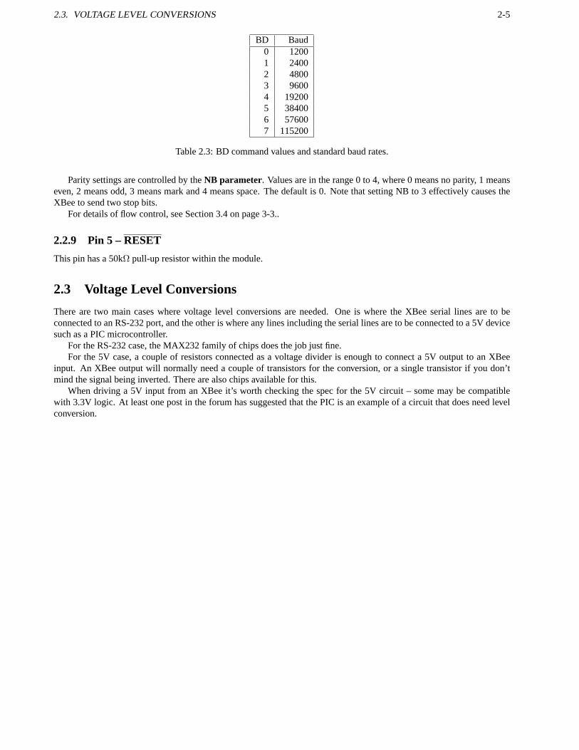
BD Baud0 12001 24002 48003 96004 192005 384006 576007 115200
Table 2.3: BD command values and standard baud rates.
Parity settings are controlled by theNB parameter. Values are in the range 0 to 4, where 0 means no parity, 1 meanseven, 2 means odd, 3 means mark and 4 means space. The default is 0. Note that setting NB to 3 effectively causes theXBee to send two stop bits.
For details of flow control, see Section 3.4 on page 3-3..
2.2.9 Pin 5 –RESET
This pin has a 50kΩ pull-up resistor within the module.
2.3 Voltage Level Conversions
There are two main cases where voltage level conversions areneeded. One is where the XBee serial lines are to beconnected to an RS-232 port, and the other is where any lines including the serial lines are to be connected to a 5V devicesuch as a PIC microcontroller.
For the RS-232 case, the MAX232 family of chips does the job just fine.For the 5V case, a couple of resistors connected as a voltage divider is enough to connect a 5V output to an XBee
input. An XBee output will normally need a couple of transistors for the conversion, or a single transistor if you don’tmind the signal being inverted. There are also chips available for this.
When driving a 5V input from an XBee it’s worth checking the spec for the 5V circuit – some may be compatiblewith 3.3V logic. At least one post in the forum has suggested that the PIC is an example of a circuit that does need levelconversion.

2-6 CHAPTER 2. ELECTRICAL SPECIFICATIONS

Chapter 3
Operation
3.1 Version and Device Information
TheVR command returns the firmware version of the RF module, as a value in therange 0 to 0xffff.TheVL command used to return a verbose description of versions, includingthe application build date, MAC, PHY
and bootloader versions. Under firmware version 10C8, this command cannot be used as an API command. If you try itas a local command it returns error status, and as a remote command it gets no response at all. In fact, the 1xEx productmanual says the command was removed from firmware version 1xC9 and all later versions.
TheHV command returns the hardware version of the RF module, in the range 0 to 0xffff. On my ordinary XBees itreturns 1742 (1744 on a few that I bought more recently), and on the Pro it returns 1842. A forum post by gworle of Digisays that plain series 1 XBees will return 17xx and Pros will return 18xx. For the series 2 modules, a plain one will return19xx and a Pro will return 1axx.
The DD command appears to be new in firmware version 1xCx. According to X-CTU, it returns the “device typeidentifier value”. On my XBees the value is 0x10000, for both the normal and Pro versions. The DD command is notmentioned in the 1xCx product manual, nor in the 1xEx manual.
TheCK command was introduced in version 10e4 according to the firmware revision history. It isn’t mentioned inthe product manual for 10e6. It returns the checksum of the configuration in RAM, as an aid to determining whether theconfiguration has changed. The value is a single byte.
3.2 Module Mode
The module mode controls how the XBee responds to data received via its UART. There are two possible modes: transpar-ent (the default) and API. In API mode there are two sub-modes, allowing data to be sent as straight binary or with certaincharacters escaped. TheAP commandselects the mode. A value of 0 (default) selects transparentmode, 1 enables APImode, and 2 enables API mode with escaped control characters.
3.2.1 Transparent Mode
Transparent mode is enabled by default. Any RF data receivedby the module will be transmitted out through the UART,and any data received from the UART will be transmitted over RF. The module has a limited buffer size for this data (100bytes), so with high transfer rates flow control must be implemented.
TheRO commandaffects the packetization timeout. Its value lies in the range 0 to 0xff, and it gives the number ofcharacter times to wait after the last character was received, before transmitting the received data as a packet. When thevalue is 0, all characters received are transmitted immediately. The default value is 3.
3.2.2 API Mode
In API mode, all data entering and leaving the module is contained in frames that cause operations or events within themodule. Frames received through pin 3 (DI) are called Transmit Data Frames. Frames sent out through pin 2 (DO) arecalled Receive Data Frames.
3-1

3-2 CHAPTER 3. OPERATION
From the command state, theAP commandenables or disables API mode. A value of 0 disables it, 1 enables it, and2 enables it with escaped control characters. The default value is 0. Operation with escaped control characters would benecessary if using XON/XOFF flow control.
3.3 Module State
At any given time, a module is in one of five states: idle, transmit, receive, command or sleep. From the idle state it canswitch to any other state, and from any other state it can switch back to idle.
3.3.1 Idle State
From the idle state:
• Serial data received in the DI buffer will switch the state totransmit.
• Valid data received through the RF antenna will switch to receive.
• If the sleep mode condition is met, the module will switch to sleep.
• If a command mode sequence is issued, the module will switch to command.
3.3.2 Sleep State
Note that in my application so far I don’t use sleep modes. Theinformation given here is therefore sketchy compared towhat the product manual contains.
Sleep is a state in which power consumption is low. For sleep mode to be entered, sleep must be enabled using theSM parameter, and either pin 9 (SleepRQ) must be asserted or the module must have been idle for the length of timespecified by theST parameter (Time Before Sleep). The parameter gives the time in milliseconds. It takes values in therange 1 to 0xffff, and the default value is 0x1388 (5 seconds).
Sleep is disabled by setting SM=0. There are four other SM values: SM=1 gives Pin Hibernate, SM=2 gives Pin Doze,and SM=4 or SM=5 give Cyclic Sleep. If SM=5, the module will wake up after the timer expires or on a pin transition.
Pin Hibernate is the sleep mode with the lowest power consumption. When it is enabled, sleep is controlled solely bythe state of the SLEEPRQ pin. The wake-up time is 13.2mS.
Pin Doze has higher power consumption than pin hibernate, but has a faster wake-up time of 2mS. It too is controlledsolely by the state of the SLEEPRQ pin.
Cyclic Sleep has the same current consumption as pin doze. Sleep is entered after a no-activity timeout given by theST parameter, and the module wakes after a period given by theSP parameter. While asleep, the RF module wakesperiodically to detect whether RF data is present. The SP parameter takes values in the range 0 to 0x6880, with the timeunit being 10mS. The default setting for SP is 0. The maximum value of 0x68b0 gives 268 seconds (4m28s). SP valuesfor the coordinator and the end devices should be equal.
For end devices that are configured for association but not currently associated, theDP commandcontrols the sleeptime, with the same unit and range as for SP but with a default of 0x3e8 (10 seconds).
When a module awakes from sleep, it will sample all active I/O lines and transmit them. If theIR parameter is set,it will collect extra samples until the limit set by theIT parameter is reached. This automatic sampling on wakeup maybe suppressed by setting bit 1 of theSO parameter(firmware 10cx).
The 1xAx product manual says that in all sleep modes, the current consumption rises dramatically if the supply voltageis more than 3.0V. In the 1xCx product manual, however, thereis no mention of this.
3.3.3 Command State
In the command state, incoming characters are interpreted as commands. There are two sub-states here: AT commandstate and API command state.
To enter the AT command state, send the three-character sequence “+++” with a guard interval before and after it.The guard interval is determined by theGT parameter: if it is set to 0x3e8 (the default), the guard interval is onesecond.The time unit is milliseconds, and the value range is 2 to 0x0ce4. The three+ characters must also be sent within a timeequal to the guard interval. TheCC parameter specifies the ASCII code of the character to be recognized where ‘+’ iswritten above; ‘+’ is the default.

3.4. FLOW CONTROL 3-3
When in AT command state, commands take the form of AT followedby the command name (two letters, or a letterand a digit), followed by an optional space and then an optional hex parameter value. Each command is terminatedby a carriage return character or a comma. If the hex parameter value is omitted, the current value will be displayed.After successful execution of a command, the module will display “OK”, or the result if the command was to display aparameter value. If an error occurred, it will instead display “ERROR”.
TheAC command will explicitly apply changes to queued parameter values and then re-initialize the module. Afterthis command is given, the module will be operating according to the parameter values.
Stored values will not be retained after a reset, unless theWR command is issued. The WR command copiesparameter values to non-volatile memory. It takes a little time: don’t send any other command until the “OK” has beenreceived.
To restore all parameters to their factory default values, use theRE command. This command does not copy therestored values to non-volatile memory, so use the WR commandafterwards if that’s required.
To perform a software reset, use theFR command. It will respond immediately with OK, and then perform the resetabout 100mS later. The FR command was introduced in firmware version 1x80, and is equivalent to powering off andthen on again.
To exit from AT command state, either send theCN commandor wait for a period controlled by theCT parameter.The CT parameter is a timeout value in the range 2 to 0x1770 (10minutes), and the time unit is 100mS. The default valueis 0x64 (10 seconds). Note: before firmware version 10e4 the maximum setting was 0xffff and the 10e6 product manualstill has that figure. The change is noted in the firmware revision history.
3.4 Flow Control
Flow control is necessary on any serial line if the rate of transmission is such that the receiving buffer cannot always beguaranteed to be emptied at a rate which prevents it from overflowing. There are two flow control mechanisms: hardwareflow control and software flow control.
• Hardware flow control is used between an XBee and its host.
• Software flow control is used between two hosts that are communicating via XBees. The XBees themselves do nottake any notice of the software flow control characters.1
Whether you need to worry about flow control at all is entirely dependent on your application.
3.4.1 Hardware Flow Control
The hardware flow control mechanism (between host and XBee) uses the RTS and CTS serial lines. The RTS line is usedby the host, to signal to the XBee that the host’s buffer is nearly full and the XBee should stop transmitting until the lineis de-asserted. In the same way, the XBee uses the CTS line to pause transmissions from the host.
When either flow control line is activated, any character already being transmitted will still be sent, and in generalmore than one character may be received after the line activation. Software needs to be written in such a way as to allowfor this. It’s the reason why the lines need to be activatedbefore the respective buffers are full, instead of when theyarefull.
3.4.2 Software Flow Control
With software flow control (host to host), two ASCII characters are given special meanings. The character 0x13 (Control-S or DC3 or XOFF) when sent across the serial link tells the other side to stop sending. The character 0x11 (Control-Q orDC1 or XON) tells the other side to resume sending. When software flow control is in use, it follows that these characterscannot be sent as part of the data stream.
As with hardware flow control, the programmer cannot assume that characters will stop being received as soon as theXOFF character is sent.
1Special thanks to Digi support for digging me out when I got confused over this.

3-4 CHAPTER 3. OPERATION
Software Flow Control with API Mode
When sending API packets it isn’t possible to avoid the need toinclude the software control characters. For instance,checksums and addresses can contain any values. Therefore the API escape mode (AP=2) exists. In this mode thecharacter 0x7d is defined as the escape character. When a host wants to transmit 0x11 or 0x13 it transmits the escapecharacter first, and then the desired character XORed with 0x20.
That’s fine so far, but now the escape character has a special meaning so it too must be escaped in the same way whenit appears in the data.
And as a final refinement, in API mode 2 the 0x7e character is also escaped whenever it appears within a packet. It isnot escaped when it appears as the first byte of the packet. This allows for recovery if any buffers do overflow in spite ofthe flow control. When overflow does happen, some bytes will be lost and a receiver will usually see just part of a packet.It can then ignore all bytes received until it sees the next 0x7e which marks the start of the next packet. One or morepackets will have been lost, but confusion is avoided.
Software Flow Control with Transparent Mode
When two XBees are being used in transparent mode for host-to-host communication, software flow control is a matter forthe hosts to arrange. If binary data is being sent (actually any data in which the flow control characters may appear), theneach host must deal with the escaping of those data characters. Since the XBees themselves attach no special meaning tothe characters sent, any escape mechanism could be used. It’s probably easiest to use the same escape mechanism as forAPI mode unless there’s a convincing reason to do otherwise.

Chapter 4
Networking
4.1 Network Types
The XBee modules support two of the IEEE 802.15.4 network types: NonBeacon, and NonBeacon w/Coordinator.
4.2 NonBeacon
By default, the NonBeacon mode is enabled. This is a peer-to-peer network. It is established by configuring each moduleto operate as an End Device (CE parameter set to 0), disabling End Device Association (A1 parameter set to 0), andsetting theID parameter andCH parameter to be identical for all nodes in the network.
4.3 NonBeacon w/Coordinator
For NonBeacon w/Coordinator mode, one module is set to act asthe coordinator by setting itsCE parameter to 1. Itspower-up is controlled by theA2 parameter. This network type uses Association to determine which end devices arecontrolled by which coordinator.
4.4 Transmission Modes
There are two transmission modes: unicast and broadcast. Unicast is the default. It supports retries; broadcast doesn’t.In unicast mode, a module receiving a packet will send an ACK back to the transmitter. If the transmitter does not
receive an ACK within 200mS, it will retry up to three times. These three retries are provided automatically, but theRRcommandwill set or read a multiplier: the number of times the (up to) 3retries will be repeated if necessary. The rangeof the RR parameter is 0 to 6, and the default is 0. The parameter was introduced in firmware version 1xa0.
TheEA parameter gives the number of ACK failures since the counter was last reset. The counter is incrementedwhen the module reaches its retransmission limit without anACK having been received. When the counter reaches 0xffffit retains that value instead of overflowing. To reset the counter, set the EA parameter to 0.
In broadcast mode, all RF modules within range will accept the transmission. No ACKs are sent, and there is noautomatic retransmission of packets. A packet is sent in broadcast mode if its destination address is DL=0xffff and DH=0.
4.5 Collision Avoidance
The modules use the CSMA-CA algorithm for collision avoidance. TheRN parameter controls the back-off exponent inthe algorithm, and has a range of 0 to 3. The 0 setting disablescollision avoidance in the first iteration of the algorithm,and is the default.
TheCA parameter sets the detection level for collision avoidance. The parameter range is 0 to 0x50, with a defaultof 0x2c. The unit is -dBm. If the energy on the channel is abovethis level, packet transmission will be delayed.
4-1
4-2 CHAPTER 4. NETWORKING
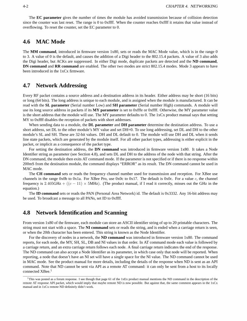
The EC parameter gives the number of times the module has avoided transmission because of collision detectionsince the counter was last reset. The range is 0 to 0xffff. Whenthe counter reaches 0xffff it retains that value instead ofoverflowing. To reset the counter, set the EC parameter to 0.
4.6 MAC Mode
TheMM command, introduced in firmware version 1x80, sets or reads the MAC Mode value, which is in the range 0to 3. A value of 0 is the default, and causes the addition of a Digi header to the 802.15.4 packets. A value of 3 also addsthe Digi header, but ACKs are suppressed. In either Digi mode, duplicate packets are detected and theND command,DN commandandRR commandare enabled. The other two modes are strict 802.15.4 modes. Mode 3 appears to havebeen introduced in the 1xCx firmware.
4.7 Network Addressing
Every RF packet contains a source address and a destination address in its header. Either address may be short (16 bits)or long (64 bits). The long address is unique to each module, and is assigned when the module is manufactured. It can beread with theSL parameter (Serial number Low) andSH parameter (Serial number High) commands. A module willuse its long source address in packets if itsMY parameter is set to 0xfffe or 0xffff. Otherwise, the MY parameter valueis the short address that the module will use. The MY parameter defaults to 0. The 1xCx product manual says that settingMY to 0xffff disables the reception of packets with short addresses.
When sending data to a module, theDL parameter andDH parameter determine the destination address. To use ashort address, set DL to the other module’s MY value and set DH=0. To use long addressing, set DL and DH to the othermodule’s SL and SH. These are 32-bit values. DH and DL defaultto 0. The module will use DH and DL when it sendsline state packets, which are generated by the module itself. For all other packet types, addressing is either explicit in thepacket, or implicit as a consequence of the packet type.
For setting the destination address, theDN command was introduced in firmware version 1x80. It takes a NodeIdentifier string as parameter (see Section 4.8), and sets DLand DH to the address of the node with that string. After theDN command, the module then exits AT command mode. If the parameter is not specified or if there is no response within200mS from the destination module, the command displays “ERROR” as its result. The DN command cannot be used inMAC mode.
TheCH command sets or reads the frequency channel number used for transmission and reception. For XBee usechannels in the range 0x0b to 0x1a. For XBee Pro, use 0x0c to 0x17. The default is 0x0c. For a valuec, the channelfrequency is2.405GHz + ((c − 11) × 5MHz). (The product manual, if I read it correctly, misses out the GHz in theequation.)
TheID command sets or reads the PAN (Personal Area Network) id. The defaultis 0x3332. Any 16-bit address maybe used. To broadcast a message to all PANs, set ID to 0xffff.
4.8 Network Identification and Scanning
From version 1x80 of the firmware, each module can store an ASCII identifier string of up to 20 printable characters. Thestring must not start with a space. TheNI command sets or reads the string, and is ended when a carriage return is seen,or when the 20th character has been entered. This string is known as the Node Identifier.
For the discovery of nodes in a network, theND commandwas introduced in firmware version 1x80. The commandreports, for each node, the MY, SH, SL, DB and NI values in thatorder. In AT command mode each value is followed bya carriage return, and an extra carriage return follows eachnode. A final carriage return indicates the end of the response.The ND command can also accept a Node Identifier as its parameter, in which case only that node will be reported. Whenreporting, a node that doesn’t have an NI set will have a single space for the NI value. The ND command cannot be usedin MAC mode. See the product manual for more details, including the details of the response when ND is sent as an APIcommand. Note that ND cannot be sent via API as a remote AT command: it can only be sent from a host to its locallyconnected XBee.1
1This was posted as a forum response. I see though that page 61 of the 1xEx product manual mentions the ND command in the description of theremote AT response API packet, which would imply that maybe remote ND is now possible. But against that, the same comment appears in the 1xCxmanual and in 1xCx remote ND definitely didn’t work.
4.9. NETWORK ASSOCIATION 4-3
When performing node discovery, theNT parameter (introduced in firmware version 1xa0) sets or reads how longthe node will wait for resopnses from other nodes. The parameter range is 0x01 to 0xfc and defaults to 0x19 (2.5 seconds).The time unit is 100mS.
Also when performing network discovery, theNO commandcontrols the network discovery options. The parametervalue is either 0 or 1, and defaults to 0. When set to 1 the local XBee will include itself in the list of discovered nodes.
TheED commandcauses an energy scan on all channels, returning the maximalenergy on each. Each energy valueis followed by a carriage return. Values of detected energy levels are in units of -dBm. Each channel’s scan time in mS is(2d ∗ 15.36, whered is the parameter value given with the ED command and is in the range 0 to 6. The total scan time isthe channel scan time multiplied by the number of channels tobe scanned.
The SC command, introduced in firmware version 1x80, sets or reads a list of channels to scan for all Active andEnergy Scans. The list is held as a 16-bit mask. In the mask, bit 0 corresponds to channel 0x0b and bit 15 to channel0x1a. On the XBee Pro, bits 0, 14 and 15 are not allowed. The default setting for the mask is 0x1ffe.
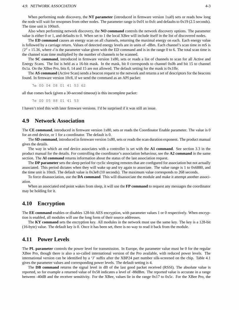
TheAS command(Active Scan) sends a beacon request to the network and returns a set of descriptors for the beaconsfound. In firmware version 10c8, if we send the command as an API packet:
7e 00 04 08 01 41 53 62
all that comes back (given a 30-second timeout) is this incomplete packet:
7e 00 05 88 01 41 53
I haven’t tried this with later firmware versions. I’d be surprised if it was still an issue.
4.9 Network Association
TheCE command, introduced in firmware version 1x80, sets or reads the Coordinator Enable parameter. The value is 0for an end device, or 1 for a coordinator. The default is 0.
TheSD command, introduced in firmware version 1x80, sets or reads the scan duration exponent. The product manualgives the details.
The way in which an end device associates with a controller isset with theA1 command. See section 3.3 in theproduct manual for the details. For controlling the coordinator’s association behaviour, see theA2 command in the samesection. TheAI command returns information about the status of the last association request.
TheDP parametersets the sleep period for cyclic sleeping remotes that are configured for association but not actuallyassociated. This period dictates when they will wake up and try again to associate. The value range is 1 to 0x6880, andthe time unit is 10mS. The default value is 0x3e8 (10 seconds). The maximum value corresponds to 268 seconds.
To force disassociation, use theDA command. This will disassociate the module and make it attempt another associ-ation.
When an associated end point wakes from sleep, it will use theFP commandto request any messages the coordinatormay be holding for it.
4.10 Encryption
TheEE commandenables or disables 128-bit AES encryption, with parametervalues 1 or 0 respectively. When encryp-tion is enabled, all modules will use the long form of their source addresses.
TheKY command sets the encryption key. All modules in the network must use the same key. The key is a 128-bit(16-byte) value. The default key is 0. Once it has been set, there is no way to read it back from the module.
4.11 Power Levels
ThePL parameter controls the power level for transmission. In Europe, the parameter value must be 0 for the regularXBee Pro, though there is also a so-called international version of the Pro available, with reduced power levels. Theinternational version can be identified by a ‘J’ suffix after the XBP24 part number silk-screened on the chip. Table 4.1gives the parameter values and corresponding power levels.The default setting is 4.
The DB command returns the signal level in dB of the last good packet received (RSSI). The absolute value isreported, so for example a returned value of 0x58 indicates alevel of -88dBm. The reported value is accurate in a rangebetween -40dB and the receiver sensitivity. For the XBee, values lie in the range 0x17 to 0x5c. For the XBee Pro, the

4-4 CHAPTER 4. NETWORKING
Value XBee XBee-Pro XBee-Pro Intl0 -10 dBm 10 dBm -3 dBm1 -6 dBm 12 dBm -3 dBm2 -4 dBm 14 dBm 2 dBm3 -2 dBm 16 dBm 8 dBm4 0 dBm 18 dBm 10 dBm
Table 4.1: Transmit power levels for the PL parameter.
range is 0x24 to 0x64. If no packets have been received since the last power cycle, reset or sleep event then the returnedvalue will be 0.Note: A post by gworle in the XBee-PRO XSC forum suggests that the RSSI reading includes any noisecomponent, so in the presence of noise the figure will be inflated. The suggestion from gworle is that packet percentageis a better measure of reliability.
Chapter 5
API Packets
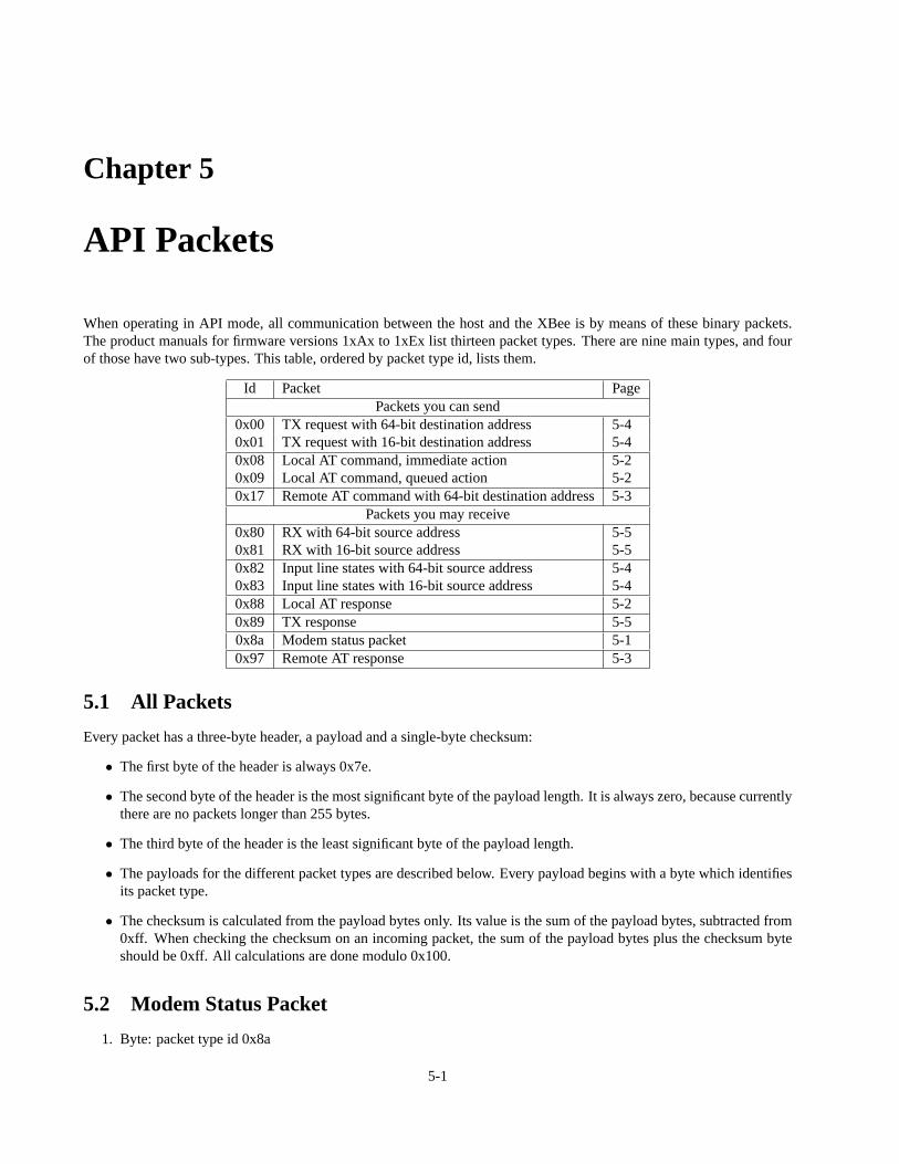
When operating in API mode, all communication between the host and the XBee is by means of these binary packets.The product manuals for firmware versions 1xAx to 1xEx list thirteen packet types. There are nine main types, and fourof those have two sub-types. This table, ordered by packet type id, lists them.
Id Packet PagePackets you can send
0x00 TX request with 64-bit destination address 5-40x01 TX request with 16-bit destination address 5-40x08 Local AT command, immediate action 5-20x09 Local AT command, queued action 5-20x17 Remote AT command with 64-bit destination address5-3
Packets you may receive0x80 RX with 64-bit source address 5-50x81 RX with 16-bit source address 5-50x82 Input line states with 64-bit source address 5-40x83 Input line states with 16-bit source address 5-40x88 Local AT response 5-20x89 TX response 5-50x8a Modem status packet 5-10x97 Remote AT response 5-3
5.1 All Packets
Every packet has a three-byte header, a payload and a single-byte checksum:
• The first byte of the header is always 0x7e.
• The second byte of the header is the most significant byte of the payload length. It is always zero, because currentlythere are no packets longer than 255 bytes.
• The third byte of the header is the least significant byte of the payload length.
• The payloads for the different packet types are described below. Every payload begins with a byte which identifiesits packet type.
• The checksum is calculated from the payload bytes only. Its value is the sum of the payload bytes, subtracted from0xff. When checking the checksum on an incoming packet, the sum of the payload bytes plus the checksum byteshould be 0xff. All calculations are done modulo 0x100.
5.2 Modem Status Packet
1. Byte: packet type id 0x8a
5-1

5-2 CHAPTER 5. API PACKETS
2. Byte giving modem status
• 0: Hardware reset.
• 1: Watchdog timer reset.1
• 2: Associated.
• 3: Disassociated.
• 4: Synchronization lost (Beacon-enabled only).
• 5: Coordinator realignment, whatever that means.
• 6: Coordinator started.
Modem status packets are sent from the XBee to its host when status conditions change. They cannot be requested by thehost. The modem status packet is identical for Series 1 and Series 2.5 XBees.
5.3 Local AT Command Packets
These packet types are useful only if the host wants to send commands to its local XBee.
5.3.1 AT Command
This comes in two varieties, depending on whether the command is to be queued, or acted on immediately. This packet issent from the host to the XBee.
1. Byte: packet type id 0x08 for immediate action, or 0x09 forqueued action.
2. Byte: frame id. This is an arbitrary value chosen by the host. The value will be returned in the response packet,except that a value of 0 will suppress the response packet.
3. Byte: first character of the AT command code.
4. Byte: second character of the AT command code.
5. Optional bytes: new value for a parameter, most significant first or (for text values) natural order. Numeric parametervalues are specified as binary bytes or words.
The Series 2.5 product manual has the same packet format, butfor the non-queued verion adds that “A string parameterused with the NI (Node Identifier), ND (Node Discover) and DH (Destination Address High) command is terminated witha 0x00 character.” The Series 1 product manual makes no mention of this.
5.3.2 AT Response
This packet is returned to the host from the XBee for each AT Command packet.
1. Byte: packet type id 0x88.
2. Byte: frame id as given in the command packet.
3. Byte: first character of the AT command code.
4. Byte: second character of the AT command code.
5. Byte: status.
• 0: OK
• 1: ERROR
6. Optional bytes: value of parameter, most significant first. These bytes are present if the command was a commandassociated with a parameter value and if the command didn’t supply a new value for the parameter.
The Series 2.5 packet has the identical format, but adds two status codes: 2 for invalid command and 3 for illegal param-eter.
1This is the first mention I’ve seen of a watchdog timer.
5.4. REMOTE AT COMMAND PACKETS 5-3
5.4 Remote AT Command Packets
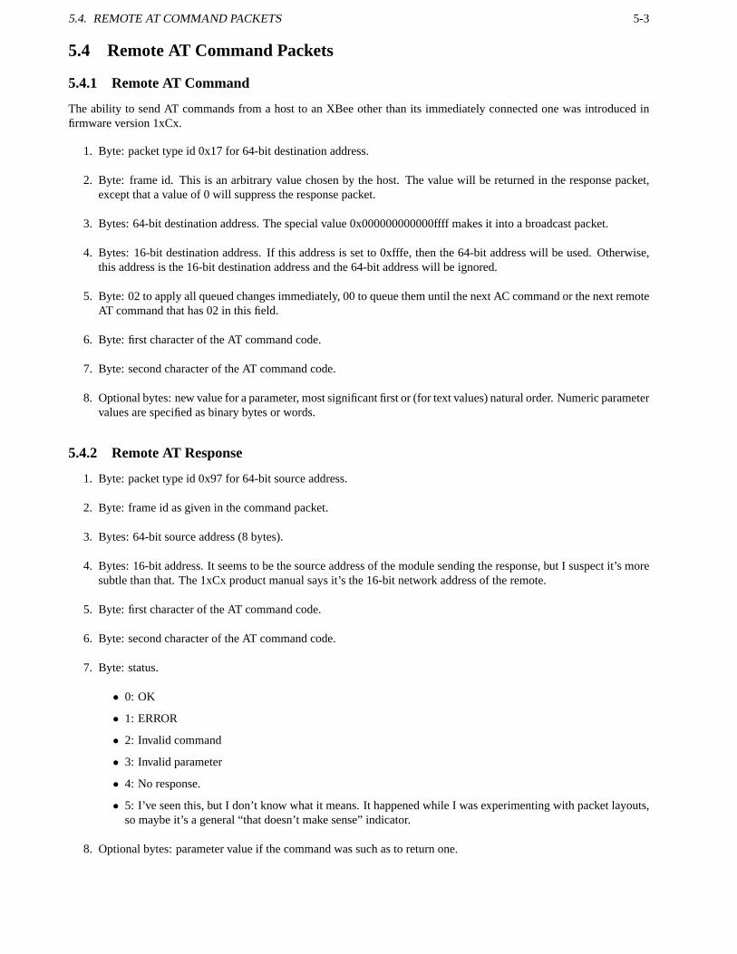
5.4.1 Remote AT Command
The ability to send AT commands from a host to an XBee other than its immediately connected one was introduced infirmware version 1xCx.
1. Byte: packet type id 0x17 for 64-bit destination address.
2. Byte: frame id. This is an arbitrary value chosen by the host. The value will be returned in the response packet,except that a value of 0 will suppress the response packet.
3. Bytes: 64-bit destination address. The special value 0x000000000000ffff makes it into a broadcast packet.
4. Bytes: 16-bit destination address. If this address is setto 0xfffe, then the 64-bit address will be used. Otherwise,this address is the 16-bit destination address and the 64-bit address will be ignored.
5. Byte: 02 to apply all queued changes immediately, 00 to queue them until the next AC command or the next remoteAT command that has 02 in this field.
6. Byte: first character of the AT command code.
7. Byte: second character of the AT command code.
8. Optional bytes: new value for a parameter, most significant first or (for text values) natural order. Numeric parametervalues are specified as binary bytes or words.
5.4.2 Remote AT Response
1. Byte: packet type id 0x97 for 64-bit source address.
2. Byte: frame id as given in the command packet.
3. Bytes: 64-bit source address (8 bytes).
4. Bytes: 16-bit address. It seems to be the source address ofthe module sending the response, but I suspect it’s moresubtle than that. The 1xCx product manual says it’s the 16-bit network address of the remote.
5. Byte: first character of the AT command code.
6. Byte: second character of the AT command code.
7. Byte: status.
• 0: OK
• 1: ERROR
• 2: Invalid command
• 3: Invalid parameter
• 4: No response.
• 5: I’ve seen this, but I don’t know what it means. It happened while I was experimenting with packet layouts,so maybe it’s a general “that doesn’t make sense” indicator.
8. Optional bytes: parameter value if the command was such asto return one.

5-4 CHAPTER 5. API PACKETS
5.5 Input Line States
This packet is used when a remote XBee and a base XBee have beenconfigured so that the remote will sample its inputs atset intervals, and transmit the results to the base. If the base XBee is configured to pass such data out through the UART,the base’s host will receive this packet.
1. Byte: packet type id 0x82 for 64-bit source address, or 0x83 for 16-bit source address.
2. Bytes: source address. Two bytes for 16-bit source addressing, or eight for 64-bit source addressing.
3. Byte: RSSI value.
4. Byte: options. If bit 1 is set, this is an address broadcast. If bit 2 is set, it is a PAN broadcast. All other bits arereserved.
5. Byte: sample quantity. This is the number of full sets of samples in what follows.
6. Word: 2-byte channel indicator msb first. Bits 14–9 are a 6-bit mask, with 1 for each ADC channel in AD5–AD0respectively that will be reported. Bits 8–0 are for the digital lines D8–D0, showing which of them will be includedin the values. Bit 15 is not used.
7. Word: optional 16-bit bitfield, with bits corresponding to lines D8–D0 as in the channel indicator. Where bits wereset in the channel indicator, the corresponding bits here show the state of the input. These bytes are not present ifthere are no lines enabled as digital inputs.
8. Words: if any bits in the channel indicator were set among the A-D inputs, those readings now follow. Each is a16-bit value with the A-D reading in the low-order 10 bits. A-D readings are given in order from AD0 to AD5.
5.6 Transmit Request
This is how a host can transmit data over the network to another host. There are three basic packet types involved, thoughas either 16 or 64-bit addressing may be used, there are two variants of two of them.
These packet types are useful only if there are multiple hosts in the network, and those hosts want to communicatewith each other.
5.6.1 TX Request
The host initiates the transfer by sending this packet to itsXBee.
1. Byte: packet type id. This is 0x00 for 64-bit addressing, or 0x01 for 16-bit.
2. Byte: frame id. This is an arbitrary value chosen by the host. The value will be returned in the response packet,except that a value of 0 will suppress the response packet.
3. Destination address. Either two or eight bytes, depending on the packet type id. For a broadcast packet, set thisaddress to 0xffff. The broadcast address is the same for two or eight-byte addressing.
4. Byte: options. This is the bitwise OR of these flags. All other bits must be zero.
• 0x01: Disable ACK. This tells the XBee not to return a response packet (see Section 5.6.3).
• 0x04: Send the packet with broadcast PAN id.
5. Bytes: data. Between 0 and 100 bytes which will be transferred to the destination host.
A comparison between Series 1 and Series 2.5 XBees for this packet type is given in Table 5.1.

5.6. TRANSMIT REQUEST 5-5
Field Series 1 Series 2.5type 0x00 (4) 0x01 (4) 0x10 (4)frame id (5) (5) (5)64-bit dest (6-13) (6-13)16-bit dest (6-7) (14-15)broadcast radius (16)options (14) (8) (17)data (15. . . ) (9. . . ) (18. . . )
Table 5.1: Comparison of API packets for TX Request. The numbers in brackets are the byte offsets for the fields.
5.6.2 RX
This is the packet that the destination host will receive, assuming the transmission was successful.
1. Byte: packet type id 0x80 for 64-bit addressing, or 0x81 for 16-bit addressing.
2. Source address. Either two or eight bytes, depending on the packet type id.
3. Byte: RSSI value. This is the absolute value of the (negative) dBm figure.
4. Byte: options. If bit 1 is set, this is an address broadcast. If bit 2 is set, it is a PAN broadcast. All other bits arereserved.
5. Bytes: data. These are the data bytes from the original TX Request packet.
5.6.3 TX Status
The originating host’s XBee returns this packet to its host,after the packet has been succesfully or unsuccessfully trans-mitted. This packet willnot be returned if the ACK was disabled in the options byte of the TX Request.
1. Byte: packet type id 0x89.
2. Byte: frame id copied from the TX Request packet.
3. Byte: status.
• 0: Success
• 1: No ACK received from the destination, and all retries havebeen attempted. A broadcast transmission willnever result in this value.
• 2: CCA failure.
• 3: Purged. This occurs when a coordinator times out of an indirect transmission. The timeout is 2.5 times thevalue of the SP parameter. I take that to mean that the coordinator was holding on to a message for a sleepingremote, and couldn’t contact the remote within the timeout so the coordinator discarded the message. But Icould well be wrong.

6 CHAPTER 5. API PACKETS

Appendix A
Baud Rates and their Accuracy
In serial communications, the baud rate should be about the simplest parameter you can get. But it isn’t. The reason isthat what you set is not always what you get. You may think you’ve specified a particular rate, but the actual rate may bedifferent to a degree that affects the quality of communication.
A.1 System Clock Frequency and UART Clock
In pretty much any digital device, there will be one oscillator (clock) that controls the timing of events. The clock is asignal source, running at a particular high frequency. Any circuitry that needs to use a lower frequency will use a sub-multiple of that frequency. The sub-multiple will be provided by a divider circuit, so any frequency which is an exactinteger division of the master frequency is available.
From that, it follows that if you want a frequency that isn’t asub-multiple of the master clock frequency, you’re goingto have to settle for the nearest approximation. And it’s here that the world tends to split into two camps. In one campwe have the PC serial port, which will normally use a crystal clock that does divide exactly to give the advertised baudrates. In the other camp we have microcontrollers, which often use clocks that are a fairly small multiple of 1MHz. Theseclocks do not divide down to give exact baud rates. The XBee isin the 1MHz-multiple camp: it has a 16MHz crystalclock.
The UART itself needs a clock signal with a frequency of 16 times the baud rate (see Receiver Operation below). It’sthis frequency that must be derived from the system clock by the divider circuit.
A.2 Available Baud Rates
As an example, take a system with an 8MHz master clock. If thisclock is to drive a UART at 9600 baud, it must be divideddown to a frequency of16× 9600 = 153, 600 Hz. The dividing factor is therefore8, 000, 000/153, 600 = 52.0833. Thatisn’t an integer value, but the nearest integer is52. The actual baud rate is then8, 000, 000/16/52 = 9615.38 baud, whichis a ratio of1.0016 (0.16%) from the exact value. Pretty good.
Now suppose we want 115,200 baud from the same master clock. The UART clock frequency must be16×115, 200 =1, 843, 200 Hz. So the dividing factor is8, 000, 000/1, 843, 200 = 4.3402. The nearest integer is 4, so the actual baudrate will be8, 000, 000/16/4 = 125, 000 baud. That differs from what was wanted by a factor of 1.085 (8.5%), which isnot at all good. This UART will not be able to communicate withone that runs accurately at 115,200 baud.
To fix this, suppose we double the master clock speed to 16MHz.The dividing factor is now16, 000, 000/1, 843, 200 =8.68, or 9 when we take the nearest integer value. The actual baud rate is therefore16, 000, 000/16/9 = 111, 111 baud.The difference ratio is 1.0368 (3.68%), which is in theory just within acceptable tolerance (see below). The master clockof the XBee is 16MHz, so this scenario represents the situation where an XBee is connected to a PC.
Overall, lower baud rates mean higher factors by which the master clock is divided. In turn, that means there is finercontrol over the frequency. So if we’re going to see problems, they’re going to happen at the highest baud rates.
A-1

A-2 APPENDIX A. BAUD RATES AND THEIR ACCURACY
A.3 Serial Line Receiver Operation
When a serial line is idle, it is in mark state (logic 1). Transmission of a byte begins with the start bit, which is a period oflogic 0. Then come the 8 data bits, and finally the stop bit which is at logic 1 level (same as the following idle state).
The receiver must recognise the beginning of the start bit, and then sample the line halfway through each of the 10 bitperiods. The receiver clock runs at 16 times the baud rate, and the receiver can sample the input line once per period ofthis clock. The sequence of operations is:
1. The start bit begins.
2. At its next clock cycle, the receiver detects that the start bit has begun. This may be up to1/16 of a bit period afterthe actual start.
3. After another 8 cycles, the receiver samples the line again. If the line is still at logic 0, the start bit is confirmed.Otherwise the initial transition is dismissed as noise.
4. After another 16 cycles the receiver samples the line. This is repeated a further 7 times, to get the values of the eightdata bits.
5. After another 16 cycles the receiver samples the line again, expecting to see the logic 1 level of the stop bit. If itdoesn’t see a logic 1 at that point, it discards the data and reports a framing error.
6. After one more cycle the receiver starts sampling the lineat every cycle, waiting for the next start bit.
From that, it follows that a receiver can accept transmittedbytes if they arrive no faster than at periods of1+8+8×16+16 + 1 = 154 of its clock cycles. If the transmitter and receiver clocks are at the same frequency, the receiver will see abyte every 160 clock cycles. Therefore the transmitter can be faster than the receiver by a factor up to160/154 = 1.039(3.9%), and in theory all will still be well.
It also follows that if the transmitter is slower than the receiver, all will be well if the period between the beginning ofthe start bit and the beginning of the stop bit (144 clock cycles for the transmitter) corresponds to more than 153 of thereceiver’s clock cycles. So the transmitter baud rate must be greater than144/153 = 0.94 of the receiver baud rate.
Any bidirectional serial channel, if there is a baud rate mismatch, will have the transmitter running faster in onedirection and the receiver running faster in the other. The tighter condition for the speed difference is for the direction inwhich the transmitter is running faster, so the ratio of 1.039 is the limiting case for the connection as a whole.
A.4 Signal Quality
We’ve seen that connecting an XBee to a PC at a nominal rate of 115,200 baud with one stop bit results in a connectionwhich is close to the theoretical limit. In theory it should still work perfectly well, but in practice there are reports ofproblems with this setup. It seems to me that the likely reason is signal degradation, probably arising from the connectingcable. This cable will have capacitive and inductive qualities, so the signal will be slightly distorted when it emergesatthe other end. And since the connection is operating so closeto the limit, any distortion or other noise is likely to be fatalto the communication quality.
A.5 Solution at 115,200 baud
Theory says that if you connect an XBee to a PC at 115,200 baud you should be able to get away with one stop bit. Inpractice, any element of noise or other signal degradation is likely to lead to data loss. The baud rates are already set tothe best obtainable values, so to prevent the problem the only remaining option is to configure the PC to send two stopbits, thus slowing its transmission rate to one that the XBeecan reliably accept.
Since at 115,200 baud nominal the XBee is running more slowlythan the PC, there is no need to slow it further. Sothere is no need for the XBee to be configured with two stop bits. However, if non-standard baud rates are used, there willbe some cases in which the XBee will be the faster transmitter. In such cases, it can be configured to send two stop bitswith the commandATNB=3. The description of that command is to set mark parity, whichis equivalent to an extra stopbit.
If instead of a PC the XBee is connected to a microcontroller,and if the microcontroller’s clock is a multiple of 1MHz,then the whole problem goes away. It doesn’t matter that neither end can support standard baud rates exactly, becausethey can still both be set to the identical non-standard rate.

A.6. DISCUSSION OF 57,600 BAUD A-3
System % Error at Baud RateModel Clock Hz 57,600 115,200 230,400 NoteXTend 60M 0.16 1.73 1.73900/868 48M 0.16 0.16 0.16Series 2 24M 0.16 0.16 0.16 1XSC 20M 3.34 -1.36 2Series 1 16M 2.12 -3.55 8.51 3XStream 8M 3.34 -1.36 4Notes:1. Zigbee or ZNet 2.5.2. Special case in code for 115,200 (16 clocks per cell).3. 802.15.4 or Digimesh.4. Special case in code for 115,200 (8 clocks per cell).
Table A.1: XBee models and baud rate accuracy.
For microcontrollers with clocks running at frequencies other than those discussed, it’s probably a good idea to usethe calculations given above to see what baud rate mismatch if any can be expected. If a mismatch is found which is asignificant fraction of the limit, then an extra stop bit on the faster transmitter may be a wise precaution.
A.6 Discussion of 57,600 Baud
At 57,600 baud there is still a mismatch between an XBee and its PC host, though to a lesser extent than at 115,200 baud.The nearest the XBee can get is 58,824 baud which means it is sending at a rate 2.12% faster than the host expects. Tojudge by postings in the forums, this mismatch generally doesn’t cause problems. However, if problems do occur then thesolution is again to slow down the faster transmitter. At 57,600 baud nominal the faster transmitter is now the XBee so itmust be configured to send two stop bits with theATNB=3command.
A.7 Baud Rate Accuracy on Other XBees
Digi have very kindly supplied me with information on how other XBees perform at higher baud rates, and I reproducetheir information here, in Table A.1.
A.8 Historical Note
If you google for this sort of stuff, you’ll find statements tothe effect that serial line communications can tolerate as muchas 10% in the mismatch of baud rates - a figure which appears to contradict the 3.9% figure derived above. The 10%figure in fact goes back to the days of mechanical teletypes, which used the stop bit purely as a delay mechanism betweentransmitted characters. Teletypes did not check the validity of the stop bit, but modern UARTs do. Teletypes, by theirnature, also took an average of the line state during a bit period. And they didn’t have the granularity issue of the 16xclock. These differences, and probably some others that I haven’t thought of, contribute to the slightly surprising fact thata modern UART does in fact have a tighter speed match requirement than the old equipment did.

A-4 APPENDIX A. BAUD RATES AND THEIR ACCURACY

Appendix B
A Study of Custom Baud Rates on theSeries 1 XBee
B.1 Introduction
/large If you think this appendix ends rather abruptly, you’ re right. It’s a work in progress, and atsome point I may or may not finish it. . .
B.2 The Calculation of Percentages
How hard can it be to calculate the percentage difference between two values? Well, it depends on what you want to dowith the result.
Suppose we have three valuesa, b andc. Suppose also thata < b < c. Which ofa andc is closer tob? To illustratewith a concrete example, assume thata = 95, b = 100 andc = 105. In pure arithmetic terms each ofa andc differsfrom b by 5, so by that measure they are equally close and we would probably express this by saying that each ofa andcdiffered fromb by 5%.
That might be fine ifa, b andc are amounts of money, but it’s less good if they are componentvalues in an electroniccircuit or (as here) baud rates. What is then of more concern (Iwould argue) is not the absolute difference but the ratiosof the values. Taking the same example and calculating the ratios gives
b
a= 1.0526
andc
b= 1.05
Not a great difference between the two ratios, but it does show that by this measurec is closer tob thana is. If we weretrying to achieve a baud rate of100 and our only choices were95 or 105, we would probably prefer the latter.
Now a common way of expressing a ratio as a percentage is to usethis formula:
pct = 100 ×
(
x
y− 1
)
Plug inb for x andc for y, and the answer comes out as−4.7619%. Interchange the two values and the answer comes outat+5%. Ignoring the difference in the sign, that’s two differentnumeric values for the same ratio.
It would be preferable to modify the calculation of percentages so that numbers in the same ratio always gave the samenumeric answer (again, apart from the sign). It turns out to be easy to do. Here’s the algorithm for calculating the ratio asa percentage, given two valuesx andy:
1. If x > y, remember the sign as1. Otherwise remember the sign as−1 and exchange the values ofx andy.
2. Calculate the ratio asx/y. This value will always be greater than or equal to1.
3. Subtract1 and then multiply by100.
B-1
B-2 APPENDIX B. A STUDY OF CUSTOM BAUD RATES ON THE SERIES 1 XBEE
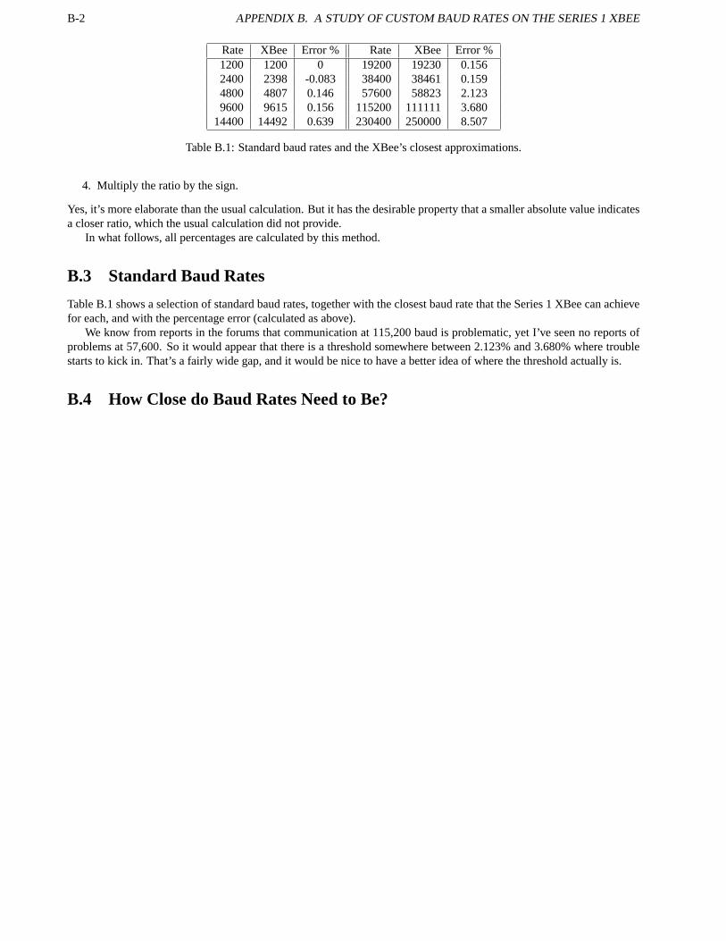
Rate XBee Error % Rate XBee Error %1200 1200 0 19200 19230 0.1562400 2398 -0.083 38400 38461 0.1594800 4807 0.146 57600 58823 2.1239600 9615 0.156 115200 111111 3.680
14400 14492 0.639 230400 250000 8.507
Table B.1: Standard baud rates and the XBee’s closest approximations.
4. Multiply the ratio by the sign.
Yes, it’s more elaborate than the usual calculation. But it has the desirable property that a smaller absolute value indicatesa closer ratio, which the usual calculation did not provide.
In what follows, all percentages are calculated by this method.
B.3 Standard Baud Rates
Table B.1 shows a selection of standard baud rates, togetherwith the closest baud rate that the Series 1 XBee can achievefor each, and with the percentage error (calculated as above).
We know from reports in the forums that communication at 115,200 baud is problematic, yet I’ve seen no reports ofproblems at 57,600. So it would appear that there is a threshold somewhere between 2.123% and 3.680% where troublestarts to kick in. That’s a fairly wide gap, and it would be nice to have a better idea of where the threshold actually is.
B.4 How Close do Baud Rates Need to Be?

Appendix C
Using X-CTU under Linux
Linux being my operating system of choice, I’ve always felt some frustration at having to dig out a Windows machinewhen I want to update XBee firmware. I now know that I was wrong in this – there’s actually no need at all to runWindows in order to run X-CTU for firmware upgrades.
Google has shown me that I’m far from being the first to discover this, but I thought I’d publish it because I’ve seen afew questions about it in the XBee forums and I’ve not yet seenthe solution posted.
The key is thewine program, and finding out how to make it work for X-CTU.Wine is available for Linux and for Mac, so in principle this explanation should also apply for Mac users. I haven’t
been able to try it on a Mac though.The wine home page ishttp://www.winehq.org/ .So if you use Linux or Mac and want to try this, here’s the recipe.Obviously, make sure you have wine installed. Typing
which wine
as a command is one way to find out. If it isn’t installed, your distribution probably has it available as a package.Now download the latest version of X-CTU. I got version 5.1.4.1 which came as a file called40002637 c.exe . If
a later version has been released by the time you read this, use the later version instead.Run the command
wine 40002637_c.exe
That installs X-CTU. If it asks questions, take the default answer every time.The first time you run wine it creates a hidden directory called .wine in your home directory. This directory contains
some configuration stuff and a subdirectory calleddrive c . Thedrive c directory corresponds to the C: drive (surprisesurprise).
You’ll find the X-CTU installation in /.wine/drive_c/ProgramFiles/Digi/XCTU and if you navigate tothere you can run X-CTU with
wine X-CTU.exe
Try it by all means, but there’s more to do before it will run successfully.Actually on my distribution (Fedora Core 11) I also got a desktop icon for launching X-CTU. Your mileage may vary.In the.wine directory there’s also a directory calleddosdevices . Thedosdevices directory contains symbolic
links. Here’s how mine looked originally:
[john@spike dosdevices]$ ls -ltotal 0lrwxrwxrwx. 1 john john 10 2010-02-13 18:30 c: -> ../drive_clrwxrwxrwx. 1 john john 1 2010-02-13 18:30 z: -> /
Now at this point the recipe forks. I’m using an RS-232 development board, so I needed to put intodosdevices asymbolic link calledcom1 to the serial port device file (/dev/ttyS0 in my case). To do that from withindosdevices :
[john@spike dosdevices]$ ln -s /dev/ttyS0 com1
C-1
C-2 APPENDIX C. USING X-CTU UNDER LINUX
Note: no colon aftercom1.Next check the permissions on/dev/ttyS0 (or whatever you’re using). I found it was owned by root and inthe
dialout group, with permissions allowing access only by those users. There are two solutions to this: 1. Make it availableto all users (you need to be root for this command):
chmod o+rw /dev/ttyS0
or 2. Add yourself to the dialout group (also as root):
usermod -a -G dialout john
and (as yourself) log out and in again for the change to take effect. Use the
groups
command to confirm that you’ve joined dialout.If you’re using a USB development board, the procedure will be similar but with a twist, because USB/dev files are
typically created only when a device is plugged in. There will be a different group to join (perhaps uucp), or to change thepermissions you have to dig in the/etc/udev directory. The device files have names like/dev/ttyUSB0 so you’llneed to set symbolic links accordingly. As you may gather from the slightly vague wording, I haven’t actually tried this.
Now you’re ready to run X-CTU. Have a development board or equivalent connected at this point, so that there’ssomething for it to see.
Launch X-CTU and the next problem becomes clear: it won’t detect any COM ports. Fear not. Click on the UserCom Ports tab and enter the port by hand. So if you’re using COM1 put a 1 in the Com Port Number box, then click onAdd. Now COM1 appears in the Select Com Port box and you can click there to select it. Hit the Test/Query button andif all has gone well you’ll get a dialog box with the modem typeand its firmware version.
Unfortunately X-CTU won’t remember the COM port next time it’s run, so you have to do the last step every time.Still, that’s not a huge imposition.
And at that point you’re ready to go. Click on the Modem Configuration tab and upgrade the firmware on your module.A few caveats:
1. The display of parameter settings didn’t look right to me,and I wouldn’t like to use X-CTU in this way for viewingor changing parameters. That’s ok by me – I’ve made my own software for that, and in this exercise I was onlyinterested in firmware upgrades.
2. X-CTU didn’t automatically discover the modem type and function set so I had to select those by hand from themenus.
3. It also didn’t manage to read the parameter values when I asked it to.
4. The menu for selecting the version of the upgrade didn’t appear in the proper order. The latest version was some-where in the middle.
5. While X-CTU was running, wine was generating various “fixme” type messages to the console. That probablyexplains the other caveats, but hey – the firmware upgrades worked!
Maybe further work would solve the caveats, but for now I’m happy with what I have. If anyone else tries this, pleaseuse the forum to let us all know how you get on.
Appendix D
Change Log
I try to record changes to this cookbook here, to make things easier for readers when I post new issues. I don’t recordsmall changes such as the correction of typos or when I make minor rewordings to make things clearer.
D.1 Changes
D.1.1 Changes in issue 1.4 (published 26 Apr 2011)
• Clarified the role of the IU parameter. My thanks to Pac for posting a pertinent question in the forum thus causingme to check the point.
• Added Table A.1, describing for XBees other than the Series 1how accurate are their baud rates at the higher rates.
• Made a start on Appendix B. This is a work in progress, and not yet useful. In time I’ll either finish or delete it.
D.1.2 Changes in issue 1.3 (published 9 Mar 2011)
• Added Section 2.3 on voltage level conversions (page 2-5).
• I learned how to make cross-references work as hyperlinks inPDF files. You can now, for instance, go to the indexand click on a page number to go to that page. Depending on the setup of your PDF viewer, you should also see inthe sidebar the table of contents instead of the page thumbnails.
D.1.3 Changes in Issue 1.2 (published 7 Mar 2010)
• Added an appendix on how to use X-CTU under Linux (page C-1). It’s a lightly edited version of a posting I hadpreviously made in the X-CTU forum.
• Added further note on analog outputs: reported not working with version 10CD (page 2-3).
• Added description of the NO (Node Discovery Options) command (page 4-3).
• Corrected the default values for the P0 and P1 commands. The default for P0 is 1, whereas previously the cookbooksaid the default for both was 0 (page 2-3).
• Added a description of the CK command (page 3-1.
• Added a note on transmission reliability at 57,600 baud (page A-3).
• Added a comment on a curious side effect of trying to read the IO parameter (page 2-3).
• Added a note in the description of the M0 and M1 parameters: under 10E6 their values cannot be read, even thoughthe product manual says they can (page 2-3).
• Clarified the description of the IS command’s parameter. Theparameter does nothing and should be ignored(page 2-1).
D-1

D-2 APPENDIX D. CHANGE LOG
D.1.4 Changes in Issue 1.1 (published 26 Jan 2010)
• Added Section 3.4 (page 3-3) to describe hardware and software flow control in more detail.
• Added cautionary note on analog outputs (page 2-3).
• Added this appendix.
D.1.5 Issue 1.0
Although it wasn’t marked as such, issue 1.0 was the first issue I published on the website and to the XBee forums.
Index
A1 command, 4-3A1 parameter, 4-1A2 command, 4-3A2 parameter, 4-1AC command, 3-3ACK, 4-1AI command, 4-3analog inputs, 2-3analog outputs, 2-3AP command, 3-1, 3-2API mode, 3-1API packets, 5-1AS command, 4-3Associated indicator, 2-1association, 4-3AV parameter, 2-3
baud rate, 2-4BD parameter, 2-4beacon request, 4-3broadcast mode, 4-1
CA parameter, 4-1CC parameter, 3-2CE command, 4-3CE parameter, 4-1CH command, 4-2CH parameter, 4-1channel frequency, 4-2channel indicator, 2-2, 5-4channel number, 4-2CK command, 3-1CN command, 2-4, 3-3collision avoidance, 4-1command state, 3-2coordinator enable, 4-3CT parameter, 3-3custom baud rates, B-1cyclic sleep, 3-2
Dn parameter, 2-1, 2-3DA command, 4-3DB command, 4-3DD command, 3-1DH parameter, 4-2digital inputs, 2-3digital outputs, 2-3disassociation, 4-3
DL parameter, 4-2DN command, 4-2DP command, 3-2DP parameter, 4-3duplicate packets, 4-2
EA parameter, 4-1EC parameter, 4-2ED command, 4-3EE command, 4-3encryption, 4-3energy scan, 4-3
factory default, 3-3features, 1-1flow control, 3-3FP command, 4-3FR command, 3-3
GT parameter, 3-2guard interval, 3-2
HV command, 3-1
I/O data packet, 2-1I/O line passing, 2-4I/O lines, 2-1I/O pins, 2-1IA parameter, 2-2, 2-4IC parameter, 2-1, 2-4ID command, 4-2ID parameter, 4-1idle state, 3-2internal voltage reference, 2-3IO parameter, 2-3IR parameter, 2-2, 2-4, 3-2IS parameter, 2-1IT parameter, 2-2, 2-4, 3-2IU parameter, 2-4
KY command, 4-3
Linux, C-1
Mp parameter, 2-3MAC mode, 4-2MM command, 4-2module mode, 3-1module state, 3-2
1

2 INDEX
MY parameter, 4-2
NB parameter, 2-5ND command, 4-2network addressing, 4-2network association, 4-3network identification, 4-2network scanning, 4-2network types, 4-1NI command, 4-2NO command, 4-3Node Identifier, 4-2node identifier, 4-2non-volatile memory, 3-3NT parameter, 4-3
Pp parameter, 2-3PAN (Personal Area Network), 4-2parity, 2-5pin doze, 3-2pin hibernate, 3-2pinout, 2-1PL parameter, 4-3power levels, 4-3PR parameter, 2-1PT parameter, 2-4pull-up resistors, 2-1
RE command, 3-3receive data frame, 3-1retries, 4-1RN parameter, 4-1RO command, 3-1RP parameter, 2-3RR command, 4-1, 4-2RSSI, 4-3
SC command, 4-3scan duration exponent, 4-3SD command, 4-3serial lines, 2-4SH parameter, 4-2SL parameter, 4-2sleep, 3-2SleepRQ, 3-2SM parameter, 3-2SO parameter, 3-2SP parameter, 3-2ST parameter, 3-2
Tn parameter, 2-4transmit data frame, 3-1transparent mode, 3-1
unicast mode, 4-1
version numbers, 3-1
virtual wires, 2-4VL command, 3-1VR command, 3-1VREF, 2-3
WR command, 3-3
X-CTU, C-1


